structural design in an automated building...
TRANSCRIPT
Ž .Automation in Construction 10 2000 181–197www.elsevier.comrlocaterautcon
Structural design in an automated building system
Rafael Sacks a,), Abraham Warszawski b, Uri Kirsch c
a Department of Construction Management, Faculty of CiÕil Engineering, Technion, Israel Institute of Technology, Technion City,Haifa 32000, Israel
b Faculty of CiÕil Engineering, Technion, Israel Institute of Technology and National Building Research Institute, Technion City,Haifa 32000, Israel
c Faculty of CiÕil Engineering, Technion, Israel Institute of Technology, Technion City, Haifa 32000, Israel
Accepted 15 March 2000
Abstract
Structural design of buildings has proven particularly difficult to automate. Parametric templates are too limited to bepracticable, and pure AI-based approaches have found little application in design offices. This paper presents ‘Intelligent
Ž .Parametric Templates’ IPT for structural design within an Automated Building System. It demonstrates that, forrectangular plan building types, comprehensive automation of general and detailed structural design is feasible. The software‘knowledge modules’ that were developed deal with rectangular buildings. IPTs for two complete slab solutions have beenimplemented. q 2000 Elsevier Science B.V. All rights reserved.
Keywords: Structural design; Computer integrated construction; Building project model; Automation; Information technology
1. Introduction
While computers are currently used to performdiverse design and management tasks in the con-struction industry, the full impact of InformationTechnology on design automation and process inte-
w xgration has yet to be felt 1 . It is expected that fullyŽ .computer integrated construction CIC will funda-
mentally change the ways in which project partici-w xpants perform and communicate 2,3 . The concept
of an Automated, Computer Integrated Building Re-Ž .alization System ABS was set out previously in
) Corresponding author.
w xthis journal 4 : its aim is to automate, as far aspossible, the generation of technologically feasibledesign and planning alternatives for selection by the
w xoperators 5 . The system stores the data describingthe project using an object-oriented Building Project
Ž . w xData Model BPDM 6 . The specific goal of theresearch presented here was to propose, develop anddemonstrate ways of automating structural design forrectangular buildings, whose shape does not changethrough their height, within such an integrated sys-tem. The principal difficulty is that of generatingdesign schema. This is the most complex part of thedesign process to computerize, as it is ‘creative’ innature.
The challenge is to address numerous and diversedesign situations effectively, without requiring exten-
0926-5805r00r$ - see front matter q 2000 Elsevier Science B.V. All rights reserved.Ž .PII: S0926-5805 00 00074-1
( )R. Sacks et al.rAutomation in Construction 10 2000 181–197182
sive libraries of preset design solutions or of exten-sive domain knowledge. Parametric templates or
w xframes are too inflexible 3 . Various ArtificiallyŽ .Intelligent AI approaches to structural design and
floor layout have been researched: Algorithmic,Ž . w xKnowledge-Based Expert Systems KBES 7 ,
Ž . w xCase-based Reasoning CBR 8 , Genetic Algo-w x w xrithms 9 , Fuzzy Logic 10 , Neural networks, and
w xhybrids of these 11 .The ‘Multilevel Selection and Development’
Ž . w xMSD method 12 proposes an algorithmic method,in which design is considered as a series of steps of
Ž .Selection of a possible solution and DevelopmentŽ .more detailed design of the assembly or part . Ateach step, development of a selected solution intro-duces the need for selection of component parts forthat solution.
ŽNumerous KBES efforts have been made e.g.w x w x w x.HI-RISE 13 , KTISMA 14 , EIDOCC 15 . Syn-
thesis of structural schemes for prefabricated slabsw xhas been demonstrated 16 ; a similar approach is
w xused by the KTISMA system 14 to propose place-ment of beams and slabs for the ceilings of apart-ments. In both of these systems, the structural designis assumed to be secondary to the architectural de-sign of the spaces; the possibility that a change in thearchitectural partitioning might allow a superiorstructural solution is not considered. In the HI-RISE
w xexpert system 13 , structural schemes for high risebuildings are formulated as being composed of dis-tinct sub-systems. Each sub-system is created byusing ‘templates’ of predefined solutions, such asframes, grids, trusses, cores, etc., which are adaptedfor use by setting values for their pre-defined param-eters.
w xThe IBDE system 17 used a number of expertsystem type modules sequentially in order to performbuilding design and construction planning. Its basicaim was to investigate a scenario in which computertechnology facilitates integration of a building teamso as to approach the cohesion that characterized the’master builder’ construction paradigm of the past.Its function implied a high degree of automation, butit lacked flexibility and cohesiveness owing in partto the absence of a comprehensive Project DataModel. This was a ‘Tool-centered approach,’ inwhich the process was essentially defined by theavailable knowledge-based program tools.
w xSystems such as ARCHIE-II 18 use Case-BasedŽ .Reasoning CBR techniques to help produce new
w xsolutions on the basis of past cases. Oxman 19details three possible steps for using a case retrievedfrom a data base of cases in a specific design situa-tion: parametric adaptation, substitution of a part,and topological adaptation. These techniques havenot commonly been employed in structural engineer-
w xing design applications. The CADRE system 20 isone example; it uses CBR to perform spatial designof large warehouses or factory sheds. The aim of the
w xSEED system 17 is to enable rapid development ofdesign alternatives at the early stages of buildingdesign. It is intended to be operated interactively bythe architects and engineers involved in the design.SEED proposes incorporation of CBR capabilities,and contains mechanisms to enable storage and re-trieval of design cases. This approach is useful heresince the operator navigates the selection and use ofthe cases or parts of cases — this is not done byrules or by any automatic program.
w xFLEXPERT 10 performed facility layout basedon the theory of fuzzy logic. Genetic algorithms havealso been used in prototype layout design systemsw x w x21 , and Park and Grierson 9 applied a Multicrite-ria Genetic Algorithm to lay out the column baysand floor heights of rectangular buildings. This sys-tem set values for predefined parameters to layoutthe structure — the number of bays and the baysizes in each orthogonal direction, the number offloors and the floor heights. Its fixed set of parame-ters does not allow for vertical openings, buildingcores, irregularly placed columns, and it does notconsider the effect of lateral loads.
These approaches have as yet had limited applica-w xtion in engineering practice 11 . They require large
w xinvestments to build, are difficult to maintain 22 ,have tackled isolated problems within the spectrum
w xof the design and construction process 16,23 , andmany were built without consideration for the re-quirements of data integration. Therefore, a newapproach to automating structural design for the typeof buildings considered here is needed. Such anapproach can, and should, make use of the advan-tages presented by product modeling technology andthe underlying object-oriented paradigm, which hasbeen adopted for construction information integra-
w xtion 1 .

( )R. Sacks et al.rAutomation in Construction 10 2000 181–197 183
The proposed approach, using Intelligent Para-Ž .metric Templates IPTs , and rooted in the object-
oriented Building Project Data Model of the ABS,represents a step in this direction. At the outset, theBPDM was refined so as to more comprehensivelyreflect the information needs of the structural designprocess. The structural knowledge modules were de-veloped using the IPT approach, and then tested indesign of rectangular buildings. Due to the limita-tions on the scope of the research, emphasis wasplaced on attempting to cover the full design process,while restricting the ‘breadth’ of the possible designalternatives at each stage. Two complete technical
Žsolutions for structural slabs Reinforced ConcreteŽ . .Flat Slabs, and RC Ribbed Joist Slabs were imple-
mented.
( )2. An automated building system ABS and its( )building project data model BPDM
On the basis of the ABS concept outlined in Ref.w x5 , a system intended for the design of multi-storybuildings with rectangular, uniform floor plans has
w xbeen proposed 4 . The ABS functions in a step-by-step manner through distinct predefined stages; it
Žuses knowledge-based software modules ‘Knowl-.edge Modules’, or ‘KMs’ to generate and manipu-
late the project information, and has on-line access tovarious construction databases. Each of the knowl-edge modules incorporates procedural knowledge ofits domain, such as structural design, floor layout,electrical system design, HVAC, etc. The knowledgemodules add new data to the building project modelat each step. The system can produce, on demand,any of the project documents required by the user.The user can respond and intervene at each stage toapprove or reject the results presented. The user canalso change the project data directly, and, if neces-sary, instruct the system to redo any previous step.
Ž .The Building Project Data Model BPDM de-fines how the data that describe a building projectwill be stored and used by the system. The majorityof previous research in the fields of Building Productand Process Models has focused on their use as toolsfor integrating the work of the individual members
w xof a project team 2,24 . Sharing building product
information is the primary goal of the building prod-uct model being developed in conformance with the
w xSTEP — ISO 10303 25 protocol. More recently,the ‘Industry Alliance for Interoperability’ consor-tium has led a modeling effort intended to produce amodel definition in the form of a set of ‘Industry
Ž . w xFoundation Classes’ IFCs 26 . Various facets ofthe ABS placed specific data storage demands on the
w xBPDM 27 . For this reason, data storage for theABS is performed using a custom designed and built
Ž .Building Project Data Model BPDM . The BPDM isw xbriefly described here, and in more detail in Ref. 6 .
The model supports storage of the informationthrough the full project life-cycle. As such, the modelschema must account not only for the varied datarequirements of different system modules, but alsofor the different ways in which they require that thedata be structured. This is a daunting challenge for
w xthe case of a generic building model 24 ; the BPDMpresented here is tailored specifically for rectangularshaped, multistory buildings whose floors do notchange shape through the height of the building.
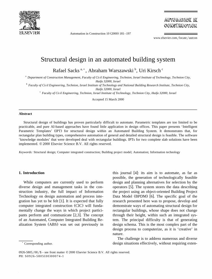
The central schema of the model has three mainaxes, which define the spatial, physical and construc-
Ž .tion activity aspects of the building Fig. 1 . Eachaxis is decomposed into three main levels, whichdescribe the whole, the assemblies and the parts ofeach aspect. The first main axis is that of the spaces:
Žthis includes the ‘Building’, the ‘Primary Space’ a–. Žfloor of the building and the ‘Secondary Space’ a–
.room or other designated area of a floor . Physically,the building is composed of ‘Building Assemblies’,–which are subdivided at the floor level into ‘Work–Assemblies’. These are defined by the technologyŽ .type of work and materials with which their partsare installed; for example, all the interior partitionwalls of drywall construction on a particular floorare grouped in a work assembly. The individual partsof a work assembly are called ‘Elements’; eachpartition in the previous example is an element. Theclasses of the third axis define the way in whichconstruction process information will be stored. The‘Task’ represents all of the work to be done by a
Ž .particular organizational unit a ‘Team’ , usually of aparticular type, e.g. ‘flooring’. Each task contains‘Activities’, which are defined as the work requiredto install one work assembly in one primary space.‘Basic Activities’ install elements and also serve to–
( )R. Sacks et al.rAutomation in Construction 10 2000 181–197184
Fig. 1. The central part of the Building Project Data Model schema.
Žlink the material resources components or bulk ma-.terials to the work assemblies and elements.
3. The intelligent parametric template technique
The challenge of automating synthesis of struc-tural layouts for the ABS required development of anew approach. While the use of simple geometrictemplates is common in most CAD systems, buildingsystems require complex templates: static definitionof parameters restricts a template to only the sim-plest of real design situations. In addition, automa-tion requires that the knowledge relating to anybuilding assembly or element be available: in mostCAD systems no knowledge is stored, and in Knowl-edge-Based Expert Systems the knowledge is stored
in a knowledge base. In the Intelligent ParametricŽ .Template IPT paradigm developed here, three in-
formation technologies — geometric templates, pro-duction rule processing and object-oriented design— are used in concert. Each IPT is based on adynamic geometric template, which incorporates dis-tinct data objects. Each object includes productionrule sets and object methods, which enable it tocalculate the values of its parameters and to displaybehavior.
For the sake of explanation, consider how a para-metric template for a reinforced concrete slab, sup-ported on orthogonal RC beams, with openings forelevator and stairwells, could be defined. To start
Žwith, a simple box which has three geometric pa-.rameters — width, depth and height could be con-
Ž .sidered as a geometric template for the slab Fig. 2a

( )R. Sacks et al.rAutomation in Construction 10 2000 181–197 185
Fig. 2. Non-feasible approach to Template design.
Žother spatial parameters, such as those defininglocation and orientation in space, are omitted here
.for the sake of clarity . The slab template also re-
quires non-geometric parameters, such as materialtype, cost, etc. Rule sets, which define how thethickness of the slab should be calculated, and howthe reinforcing should be apportioned, could also beadded. Any particular instance of a simple slab, withonly one bay, no holes and no beams, could bedefined using this template. Now consider addingsupporting beams along the sides of the slab, as
Ž .shown in Fig. 2 b . One possibility would be todefine a template object with 11 parameters: slablength A, width B, depth D, and the width anddepth of each of the four beams b , h , b , h , etc.1 1 2 2
The logic of this approach implies that the number oftemplates, which would be required in order to sat-isfy all possible design situations, would be combina-torial. In addition, the numbers of parameters andrules grow as the complexity of the template in-creases. Any irregularity would also require addi-
Fig. 3. Intelligent Parametric Template design.

( )R. Sacks et al.rAutomation in Construction 10 2000 181–197186
tional parameters. This approach is not feasible, andis therefore rejected.
A technique is required whereby a template canadapt itself to all possible geometric and topologicalconfigurations that might be required. A good solu-tion must allow for description of situations in whichthere are any number of bays in each direction, thebay sizes can differ, beams can be present or absentand have varying dimensions, the slab can haveopenings, etc., using just one basic parametric tem-plate. The solution must also account for the fact thatthe rules and algorithms for different work assemblytechnologies are significantly different; for example,the layout of a Reinforced Concrete Flat Slab is quitedifferent from that of a Concrete and Steel Compos-ite Deck.
The IPT approach provides these capabilities. Thesolution is to define an IPT not as one complexparametric object, but rather as an intelligent mech-anism for instantiation of a set of objects and ofthe relations between them. The geometric base ofan IPT is composed of many distinct data objectsrather than being limited by a single predefinedtemplate. Its object-oriented design enables an IPT todynamically instantiate its parts — the number andnature of parameters are set according to the geome-try of each specific design situation.
A simplified IPT for a slab such as in Fig. 2Ž .would comprise as seen in Fig. 3a the following.
Ž .1 An object definition for a slab assembly as awhole.
Ž .2 Object definitions for a slab section and abeam. The location and spatial orientation of eachelement is defined using co-ordinates and links toother elements to the slab assembly object; its shapeand other local properties are defined by parametervalues.
Ž . Ž3 Object methods object-oriented software.functions for creating instances of the slab assem-
bly, slab sections and beams, for linking the beamsand slab Sections to the slab assembly with ’part of’relationships, and for computing or deducing thevalues of the parameters of each instance. The meth-ods incorporate AI strategies such as rule-processingand inferencing, case-based reasoning, fuzzy logic,
Žgenetic algorithms, neural networks, etc. in the cur-rent demonstration system, only rule processing has
.been used .
For example, consider how beams would be laidŽ .out for a one-way slab, such as that in Fig. 3 b . A
possible algorithm, expressed in ‘pseudo’ code, mightbe:
Slab assembly :: instance beams� FOR EACH adjacent column pair
� IF the axis direction is perpendicular to anadjacent slab section span directionOR IF there is no adjacent slab
� 4THEN instance a beam4
4
Ž .The resulting beams are shown in Fig. 3 c . Theoverall slab data generated are stored as a set of
Ž .linked object instances Fig. 3d , which togetherfully describe the slab and enable it to exhibit ‘be-havior’ — for analysis and detailed design.
Full-scale IPTs use objects based on the assem-blies and parts parent objects of all three aspects ofthe BPDM. Inclusion of ‘Activity’, ‘Basic Activity’and ‘Resource’ objects enable an IPT to provide theconstruction process data as well as the physicaldesign data.
In summary, an IPT can be defined as Aa collec-tion of object definitions, rules and methods, whichfully describe a set of building spaces or elementsand define the ways in which they can be insertedinto a building modelB. The object class definitionsinclude the attributes of each class. The rules and
Ž .methods the knowledge of an IPT are stored as partof its object definitions. Also, each rule set in an IPTmay be used by more than one knowledge module.An important feature of the IPTs and the object-ori-ented BPDM structure is that not only class proper-ties and methods are inherited, but also IPT rule sets.This structure for storing the knowledge greatly fa-cilitates the addition of any new technical solution:this is done simply by defining it as an IPT, definingits class inheritance, and adding only those specificproperties, methods and rules that distinguish it from
Ž . Ž .the previously defined solution s from which itw xinherits. Further detail can be found in Refs. 6,28 .

( )R. Sacks et al.rAutomation in Construction 10 2000 181–197 187
4. General and detailed structural design — anoverview
Engineering design is commonly divided into fourw xmain phases 29 : planning and clarifying the task
Ž .specification of information , conceptual designŽ .specification of principle , embodiment designŽ . Žspecification of layout and detail design specifica-
.tion of production . This breakdown is apparent inthe design phases defined for the ABS which in-clude: Brief Generation, Conceptual, General and
w xDetailed design 4 . In the first phase, the client’srequirements and the site data are acquired andclarified. Next, the building’s shape, height, positionand the number of floors are proposed. Generaldesign covers the selection and layout of all of thebuilding’s spaces, assemblies and their components,and construction activities. The dimensions and de-tails of the objects are calculated and added in theDetailed design phase.
The discussion that follows focuses only on thestructural aspects of the General and Detailed designphases for rectangular buildings intended for office,commercial, or light industrial use. In such build-ings, partitioning of each floor is usually definedafter general design is completed; changes in thepartitioning of the floors may also be commonthrough the building’s life.
In General Design, the spacing of the verticalŽ .structural elements columns andror walls must
facilitate partitioning suitable for the function of thebuilding’s spaces; the placement of the building’s
Ž . Žcore s must also satisfy both architectural transport.and fire safety and structural requirements. The
ŽFig. 4. The sub-stages of General Design. Abbreviations defined.in text.
Fig. 5. The sequence of General Design.
sub-division of the core spaces must fulfill spaceŽ .requirements e.g. storage, restrooms, etc. . The
strategy adopted here is to divide general structuraldesign into: layout of the structural scheme, position-
Ž .ing of the core s , layout of the core spaces and corewalls, and finally fixing positions for columns. Thisis shown in an SADT diagram in Fig. 4 and insimplified form in Fig. 5.
In the first sub-phase of general design, the Struc-Ž .tural Scheme Knowledge Module SSKM receives
the perimeter of the building and its position on thesite, the number of floors, and the space require-ments for the building’s core spaces as input. Itcalculates optimal column spacings subject to thefloors’ functional requirements, and then selects boththe foundation system type and the type of horizontal
Ž .load system the latter have yet to be implemented .Its output includes the basic grid of the gravity load
Ž .support systems, building axes and the location ofŽ .the center of the core s . The module uses the data
bases of Functional Systems and Work AssembliesŽ . w xexpressed as IPTs as well as a Land Data Base 4 .

( )R. Sacks et al.rAutomation in Construction 10 2000 181–197188
Next, the Floor Design Knowledge ModuleŽ .FDKM fixes the specific shape and sub-division ofeach of the core spaces around the core positions,which were set by the SSKM. Candidate IPTs forcores of different compositions and geometries areevaluated, and the selected IPT is processed to layout the core spaces. This has not been detailed in thecurrent work.
Lastly, the Functional System Knowledge ModuleŽ .FSKM selects a work assembly for each structuralassembly, using IPTs stored in the Work AssemblyData Base, and lays out the structural elements. Forthe slab systems, the elements are columns, beams,slab strips, etc. The input is the gravity load systemgrid, the core spaces and the partitions. The modulealso uses external data base files, containing informa-tion on materials, imposed loads, design codes, etc.
In the Detailed Design Phase, the Work AssemblyŽ .Knowledge Modules WAKMs perform detailed de-
sign of the elements of each Work Assembly in thebuilding. The dimensions and other specifications ofeach element are set, and the activity and resourcedata objects are instanced and evaluated. Each kindof Work Assembly has a specific WAKM, much ofwhose functioning involves initiating the methodsand rule sets of the IPTs on which the Assembly wasbased.
Of course, some of the knowledge used by thevarious design modules is common to two or moreof them. For example, rules governing the feasibilityof a particular type of slab may be used in both thestructural scheme design and in functional systemselection processes. This has been implemented byembedding the specific knowledge about a technicalsolution within its Intelligent Parametric Template. Itshould be noted that the approach applied here to thestructure might equally be applied to other buildingsystems; terms such as ‘Functional System’ and‘Work Assembly’ are generic.
( )5. Structural system knowledge module SSKM
The structure of any building must satisfy threekey structural requirements: support of gravity loads,resistance of horizontal loads and foundation. Atechnological solution must be selected for eachrequirement. Candidate IPTs are checked for feasibil-
ity, those found feasible are evaluated, and that withthe lowest cost is selected.
Throughout the following discussion, a numericalexample is used to enhance the explanation. Thebasic data describing this example are; building plandimensions of 23=27 m, seven floors, open-planoffice space is required on all floors, and the corespace must include a stairwell and three elevatorshafts. Symmetric positioning of the cores is as-sumed; in all of the core positioning IPTs the coresare placed such that their combined center of stiff-ness is coincident with the center of inertia of thebuilding as a whole. For the sample building, fireescape access rules and occupant traffic requirementsallowed a single central core solution to be selected.
The minimum possible column spacing in eachŽ .direction X and Y is set by rules that express the
architectural requirements imposed by the functionsof the building spaces. For example, the minimumcolumn spacing that allows open-plan office design
w xis 6 m 30,31 . In order to generate candidate sets ofcolumn spacings in each direction, the overall build-ing dimensions are divided into increasingly largernumbers of spans until the minimum column spacingis reached. The 27-m building depth can be dividedinto two spans of 13.5 m, three spans of 9.0 m, orfour spans of 6.75 m; division into five spans of 5.4m would be insufficient for open-plan offices. Addi-tional rules check whether the building’s width isless than three times the minimum column spacing:if so, it would be convenient to place a narrowercorridor along the length of the building, and theminimum spacing for one of the longitudinal bayswould be set to match the minimum width for acorridor.
In order to select the column spacing that willresult in the lowest overall structure cost, the avail-able slab solutions must be assessed. The SSKM firstassesses possible solutions by processing the feasibil-ity rules contained in the IPT for each available slabsolution, and for each proposed set of column spac-ings. The factors that govern the feasibility of aparticular slab type include: the type of solutionselected for resisting horizontal loads, the magnitudeof the loads on the slab, the function of the spacebelow the slab and other non-structural systems andconsiderations, and the availability of necessary con-struction equipment and competent work teams.

( )R. Sacks et al.rAutomation in Construction 10 2000 181–197 189
Table 1Sample rules of a ribbed slab IPT
Ž . Ž . Ž . Ž .Ribbed Joist Slab Rule 1 Source 2 CommentrNote 3
w x Ž .The minimum slab depth required is at least 32 , Expert interviews Joists ribs will span1r24 of the larger column spacing in the longer direction
w xThe minimum depth required is at least 32 , Expert interviews Hidden beams will span1r16 of the smaller column spacing in the shorter direction
w xThe minimum depth of the slab is at least 15 cm 33
Ž .Three sample rules for a Ribbed Joist ReinforcedConcrete Slab without drop beams, which enablechecking whether the slab will conform to a maxi-mum depth restriction imposed by overall buildingheight restrictions and minimum clear heights re-quired for each floor function, are listed in Table 1.
Each of the possible slab typercolumn spacingcombinations that are feasible are then evaluated andcompared. The direct cost of the slab itself, and thecost of external building finishes, which must beadded for any increase in building height, increase asspans are lengthened; other costs, such as the cost ofthe building core and the foundation cost, decreaseas column spacing is increased. Also, the value ofthe resulting space to the user may rise as spans
increase. All of the costs are combined, so thatdifferent column spacing and slab combinations can
Žbe compared currently, only direct costs are com-.puted . The cost factors are estimated by processing
the IPT evaluation rules of each feasible slab solu-tion. The base costs are drawn from a database ofconstruction costs similar in format to the ‘R.S.
w xMeans Square Foot Costs’ catalog 34 , in which thecosts per unit area of different assemblies are listedas a function of the assembly type and the typicalspan or bay size.
The final column spacings can now be selected.The user is presented with a graph showing therelationship of cost per unit area to column spacingfor different technical solutions. The lowest cost
Fig. 6. User Interface showing the relationship of cost per unit area to span for feasible slab solutions.

( )R. Sacks et al.rAutomation in Construction 10 2000 181–197190
Žsolution, which also satisfies all other criteria in this.case at least one direction greater than 6.0 m , is
Ž .highlighted as the default Fig. 6 . For the examplebuilding, spans of 4.5 and 6.6 m are suggested. Afterapproval by the user, the axes are placed at thesespacings.
( )6. Floor design knowledge module FDKM
In the current implementation, the secondaryŽ .spaces that make up the building’s core s are now
laid out by selecting and running a core IPT, whichŽarranges the stair wells, elevator shafts, etc. note
that only the position of the core was set in the.previous stage .
( )7. Functional system knowledge module FSKM
Once floor layouts are complete, the FSKM se-lects a work assembly for each of the functionalsystems, and lays out the elements of each workassembly. The main structural goal at this stage is toselect a solution for each of the slabs and lay out itselements. The slab assembly according to which thespacings were set cannot be adopted automatically asthe slab system for all of the building’s floors. Thereare three reasons for this:
v The final column spacings may be different fromthose which were associated with the optimumslab system at the structural scheme design phase,
v ŽMore detailed project data is now available e.g..imposed loads, core walls, etc.
v The same slab system may not be appropriate forall of the floors of the building. It is possible that
Žfloors with loading or other constraints such as.height limits , which differ from the norm, may
have different slab systems. Slabs in parking floors,for example, are likely to be different from thosein upper floors.
For each floor, selection rules are processed foreach feasible slab solution IPT. At this stage, thelevel of detail is greater than that at the schematicstage: the spans have already been fixed, and specificfloor loads and other performance parameters have
been set and can be used for detailed evaluation ofthe slab. The most economical slab solution is se-lected from those that are feasible. The user canperuse the selections and change them if necessary.As can be seen in Fig. 7, the system selected a
Ž .reinforced concrete ribbed joist slab with hiddenbeams for floor 6 of the example building. Thenominal depth, span directions, and nominal spanlengths of the slab are calculated and stored in aninstance of the ‘Ribbed Slab’ class. In the example,–the nominal slab depth is 30 cm, the beams span inthe X direction with nominal spans of 4.5 m, and theribs span in the Y direction with nominal spans of6.6 m. Note that the opening in the slab for the stairsand elevators has not yet been taken into account.
The slab IPT now lays out its elements by pro-cessing its methods and rules. The slab solution IPTsare based principally on the ‘Work Assembly’ and‘Element’ class definitions of the Building Project
Ž .Data Model as shown in Fig. 8 . Thus, one WorkAssembly object is inserted in the Building Project
Ž .Model to represent the slab the object is ‘instanced’ ;next, the IPT ‘instances’ multiple Element objectsfor the beams, columns, slab strips or slab sections,etc., and links them to the Work Assembly instance.
Fig. 7. Work Assembly Selection Screen.

( )R. Sacks et al.rAutomation in Construction 10 2000 181–197 191
ŽFig. 8. Ribbed Slab IPT Classes and Relationships dashed lines.denote intermediate classes in the hierarchy, which are not shown .
In the example, the RC ribbed slab IPT will instanceŽ .one ‘Ribbed Slab’ work assembly , a ‘Column’–
Ž . Ž .element for each column, a ‘Beam’ element ob-ject for each beam, a ‘One Way Slab Section’– – –Ž .element object for each unique field of continuousjoists, and an ‘Activity’ object as follows.
Ž .1 Columns. The columns are included with thework assembly of each floor as they will be built
Žtogether with the slab the advantage of this ap-proach is that it effectively supports the construction
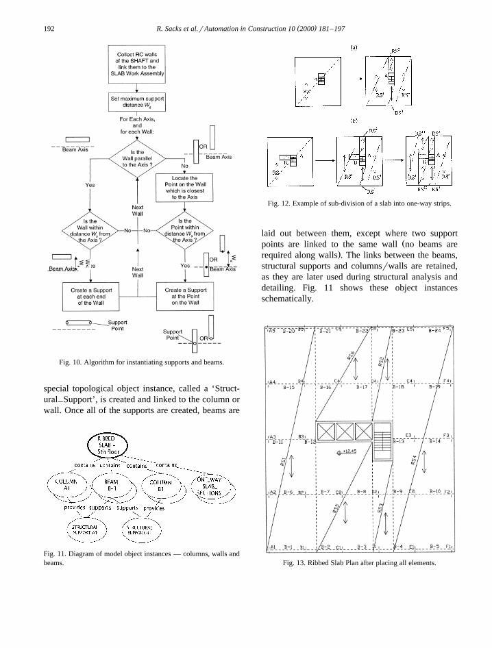
.planning view of the building . Columns are placedat each intersection of building axes, except for thoseintersections that fall within a core secondary space,
Ž .or those that fall within one passage width d fromw
a core wall. As can be seen in Fig. 9, two situationsare possible. In the first case, where the distance
Ž .from the proposed column to a core wall d iswc
less than d , the slab support lines are changed inw
order to utilize the core for support. The ends of thecore walls are defined as support points and thebeams or slab strips will rest on them. In the secondcase, where d )d , columns are placed at thewc w
intersections of the building axes.Ž .2 Beams. The rules for beam layout for the RC
Ribbed Slab IPT state that a beam will be placedbetween each two columns along an axis, or betweena column and a wall along the axis, in the beam spandirection. While the columns are linked to the Slabwork assembly, the core walls are not, and so deter-mining which core walls will participate in support-ing beams requires that the method scan all the corewalls in order to take them into account in laying outthe beams.
A wall can support a beam if the beam axis fallsalong the wall length, or if it falls a short distance ws
from the wall, whether parallel or at right angles; inthis case, the beam axis is diverted to the wall edge.The algorithm for locating support points along thewalls is shown in Fig. 10. At each such point, a
Fig. 9. Placement of Columns near Building Cores.
( )R. Sacks et al.rAutomation in Construction 10 2000 181–197192
Fig. 10. Algorithm for instantiating supports and beams.
special topological object instance, called a ‘Struct-ural Support’, is created and linked to the column or–wall. Once all of the supports are created, beams are
Fig. 11. Diagram of model object instances — columns, walls andbeams.
Fig. 12. Example of sub-division of a slab into one-way strips.
laid out between them, except where two supportŽpoints are linked to the same wall no beams are
.required along walls . The links between the beams,structural supports and columnsrwalls are retained,as they are later used during structural analysis anddetailing. Fig. 11 shows these object instancesschematically.
Fig. 13. Ribbed Slab Plan after placing all elements.

( )R. Sacks et al.rAutomation in Construction 10 2000 181–197 193
Ž .3 Slab section. In the example IPT, slab sectionlayout is done using a recursive algorithm, whichaccounts for one opening in the slab at each recur-
Ž .sion, as shown in principle in Fig. 12 a . The algo-Ž .rithm starts with a single slab section RS spread
over the entire floor area. It then replaces the slabsection with new parallel and contiguous sectionsŽ 1 4. ŽRS to RS , removing one opening area denoted
. Ž .‘A’ in the figure . Fig. 12 b shows how a slab withmore than one opening is sub-divided: slab section‘RS’ is first divided into sections ‘RS1’, to ‘RS4’
Žconsidering opening ‘A’ only opening ‘B’ is ig-.nored . In the second step, opening ‘B’ is consid-
ered; this leads to slab section ‘RS1’ being furthersub-divided into sections ‘RS11’, ‘RS12 ’ and ‘RS13’.In this way, any slab can be divided into unique slabsections such that each slab section contains ribs ofuniform spans.
In the example under discussion, the slab obtainedafter layout of all of its elements is shown in Fig. 13
— the drawing itself is produced automatically usingthe draw methods of the IPT objects. The values ofthe dimensions and other parameters of the elementshave not yet been computed — these will be filled inat the detailed design stage.
( )8. Work assembly knowledge modules WAKMs
In the final step of the design process, the WorkŽ .Assembly Knowledge Modules WAKMs detail the
elements. These modules use IPT methods to analyzethe work assemblies and to compute the details ofthe elements of which they are comprised. For thestructural work assemblies, this includes structural
Žanalysis and element design selection of standardsteel sections or, in the case of reinforced concrete,
.fixing member dimensions and reinforcing detailing .The functioning of a typical WAKM performing
detailed design is presented by continuing the exam-
Fig. 14. Ribbed Slab IPT user interface dialog screen.

( )R. Sacks et al.rAutomation in Construction 10 2000 181–197194
ple begun in the previous section. At the layoutstage, the slab was divided into distinct strips, insuch a way that all of the ribs in a given section haveidentical spans. The initial thickness for the slab isassumed to be the thickness calculated during thegeneral design stage. The initial sizes of the columnsare set by a method of the column class; at this time,the initial slab depth is checked for resistance topunching shear at the head of each column. A sizing
Žmethod uses production rules based on the nominalslab loads, rib and beam spans and non-structural
.requirements , and the Resource Requirements DataBase, to select the filler block type and size, and toset initial dimensions for the widths of each rib andbeam. The user can edit these selections: Fig. 14shows an instance of a Ribbed Slab IPT, togetherwith a secondary dialog box which shows the datafor one of the columns.
The detailed design method then continues byŽanalyzing each set of ribs a ‘one way slab sec-– – –
.tion’ instance as continuous beams of ‘T’ cross-sec-tion. The resulting moment, shear and deflectionresults are stored in temporary instances of the‘RC Design Section’ class, which are placed at each– –end and at the center of each span of each ribsection. This class defines a typical reinforced con-crete cross section with attributes of section depthsand widths, top and bottom steel reinforcement ar-
Žeas, and structural analysis results moments, shears.and deflections . It has a method that calculates the
steel area required at the top and bottom of theSection for resisting the applied moments. The beamssupport the ribs; the reaction results from the ribanalysis define the beam loadings. The beams arealso analyzed as continuous beams, also of ‘T’ crosssection, using the same algorithm as is used for theribs.
After structural analysis, the steel reinforcement isdetailed. As defined by the Building Project DataModel, material resources are consumed by ‘Basic–Activities’. Therefore, an instance of the ‘Fix Steel’–‘basic activity’ class is first created and linked to theFlat Slab activity. The Ribbed Slab IPT places rein-
Ž .forcing mesh for cracking prevention over the ribs,places individual bars along each rib and above eachrib over the beams, and places individual bars andstirrups along each beam, and along each beamabove each column.
The information for each group of bars in anŽ .individual element beam, column, etc. is stored in
an instance of the ‘Rebar Use’ class. Each such–instance is linked to a slab work assembly throughthe fix steel basic activity. At first, the bar group isdefined only by its position, orientation, and length.A ‘Rebar Use’ class method then calculates and sets–the number of bars, the bar diameter, material typeand shape. While the number of bars in a group isstored in the ‘Rebar Use’ instance, the diameter,–type and shape are stored in instances of the ‘Rebar’
Ž .class. Fig. 15 shows a how these classes are re-Ž . Ž .lated, b how they are instanced, and c how the
rebars are drawn. This data structure allows a latermethod to collect all similar ‘Rebar’ instances andrationalize them into as small as possible a list ofdifferent bars for manufacture and delivery to site.
ŽThe ABS can produce outputs drawings, rein-.forcing schedules, bills of quantities, etc. automati-
cally. In the current implementation, the productionof detailed structural drawings, reinforcing meshschedules, and isometric views have been success-
Fig. 15. The Definition of Reinforcement in the Building ProjectData Model.

( )R. Sacks et al.rAutomation in Construction 10 2000 181–197 195
Fig. 16. Detailed Ribbed Slab filler block layout drawing.
fully tested. Fig. 16 shows the resulting detailedribbed slab layout.
9. Discussion and conclusions
A prototype computer system for the structuraldesign of rectangular-shaped buildings with rectan-gular floors has been implemented as a vehicle for
Ž .testing the ‘Intelligent Parametric Template’ IPTstrategy for automated design. The system is part ofa general framework of an Automated Building Sys-tem and is based on the Building Project Data Modeldesigned for the automated system. The structuraldesign modules presented in this paper highlight anumber of features of the Automated Building Sys-
tem, its Building Project Data Model, and the IPTapproach to design automation.
As distinct from the data sharing approach adoptedin most Building Project Data Model developmentefforts, the ABS addresses Computer Integrated Con-struction not only as an issue of data sharing be-tween project participants, but also aims for compre-hensive automation of the building process. For thisreason, the data model of the ABS is specificallydesigned to suit the system’s processing stages. Itclosely links the three main aspects of project dataŽ .Space, Product and Activity at each of three mainlevels of detail, to provide a coherent basis forstoring the information that the ABS modules pro-duce.
( )R. Sacks et al.rAutomation in Construction 10 2000 181–197196
The IPT approach is different to that of mostother AI-based tools. Instead of collecting all of theknowledge of a particular design domain in a knowl-
Žedge base which includes a system decomposition.tree, constraints, functions and rules , the knowledge
required for each design solution is encapsulatedwith that solution. IPTs encapsulate production rules,simple and AI algorithms, data base queries and userqueries together with object definitions that are rootedin the BPDM. Thus, addition of a new buildingtechnology does not require editing the knowledgebase, but simply programming the new technology’sobjects and behavior and then registering its exis-tence in the system. The object-oriented nature of theapproach also enables the effort that must be in-vested in programming IPTs to be distributed amongvarious organizations in the industry; the fact that itis based on a common Building Project Data Modelensures compatibility. Inheritance of object class def-initions, rule sets and object methods make the addi-tion of new IPTs relatively cheap when comparedwith the investments required for expanding existingsoftware or expert systems. These features may provevaluable in enabling the construction industry toovercome the inflexibility inherent in its legacy soft-ware, which has been a significant obstacle to thedevelopment of computer integrated construction.
The system’s success in producing designs forrectangular buildings of various sizes and heights,with different core configurations, using only oneIPT for each solution type, indicates the suitability ofthe IPT approach for automating structural design.The approach combines knowledge-based program-ming with project model technology and geometrictemplates: an IPT can be defined as Aa collection ofobject definitions, rules and methods, which fullydescribe a set of building elements and define theways in which they can be inserted into a buildingmodelB. Two full IPTs, for design and detailing offlat and ribbed reinforced concrete slabs, have beenimplemented and tested.
ŽThe role of the users of the system theownerrdeveloper, professional consultants, contrac-
.tors, etc. has been clarified. Although the systemmay be technically capable of progressing withoutuser involvement, it is not realistic to expect thatsuch designs will be acceptable. This is becauserequirements are not stated explicitly in certain cases,
and because the system cannot deal with local devia-tions from regular design that cannot be predicted apriori. The value of the system is not in achievingcomplete automation, but in achieving a degree ofautomation which relieves the users from the vastmajority of repetitive design tasks.
The system has two important limitations.At present, it only deals with rectangular-shaped
buildings with uniform floor sizes. It is expected thatpreparation of IPTs for buildings whose shape iscomposed of rectangles should be straightforward;however, the use of the IPT method for arbitrarybuilding shapes is not contemplated.
Initially, each basic IPT must be programmed.The IPT method does not provide any solution to theproblems associated with knowledge elicitation for
w xknowledge-based expert systems 7 . The system doesnot at present have any automated ‘learning’ capabil-ity, although this is desirable in a full system.
ŽWhile certain issues have yet to be resolved suchas expanding the system to deal with more complexbuilding shapes, layout of rooms on a building floor,and developing a model for assessing the value of
.net space to the developer , these are mostly techni-cal in nature. The present system indicates that largepotential savings could be achieved through use of afull-scale system in the building industry. Firstly, thetime required for a user to produce design alterna-tives, and to evaluate their cost, would be reducedfrom days to hours. This could both reduce directdesign costs and enable consideration of more alter-natives than is currently practical. Secondly, thesystem is capable of producing designs of high qual-ity, in the sense that the solutions selected are cost-effective and fulfill the requirements defined forthem. Lastly, the integrated nature of the systemcould reduce the construction costs associated withdesign coordination conflicts between the designs ofdifferent disciplines.
References
w x1 F.P. Tolman, Product modeling standards for the buildingand construction industry: past, present and future, Autom.
Ž .Constr. 8 1999 227–235.w x2 P. Teicholz, M. Fischer, Strategy for computer integrated
construction technology, ASCE J. Constr. Eng. Manage. 120Ž . Ž .1 1994 March.

( )R. Sacks et al.rAutomation in Construction 10 2000 181–197 197
w x3 T. Seebohm, W. Wallace, Rule-based representation of de-Ž .sign in architectural practice, Autom. Constr. 8 1998 73–85.
w x4 R. Sacks, A. Warszawski, A project model for an automatedbuilding system: design and planning phases, Autom. Constr.Ž .7 1997 21–34.
w x5 A. Warszawski, Industrialization and Robotics in Building,Harper and Row, New York, 1990.
w x6 R. Sacks, Issues in the development and implementation of aproject model for an automated building system, Int. J.
Ž . Ž .Constr. Inf. Technol. 5 2 1998 75–101, Salford Univer-sity, Salford, UK.
w x Ž .7 F. Hayes-Roth, D.B. Lenat, D.A. Waterman Eds. , BuildingExpert Systems, Addison-Wesley, Reading, MA, 1983.
w x8 A. Aamodt, E. Plaza, Case-based reasoning: foundationalissues, methodological variations, and system approaches,
Ž . Ž .Artif. Intell. Commun. 7 1 1996 .w x9 K.-W. Park, D.E. Grierson, Pareto-optimal conceptual design
of the structural layout of buildings using a multicriteriagenetic algorithm, Comput.-Aided Civ. Infrastructure Eng.
Ž .14 1999 163–170.w x10 A. Badiru, A. Arif, FLEXPERT: facility layout expert system
Ž .using fuzzy linguistic relationship codes, IIE Trans. 28 4Ž .1996 295–309.
w x11 R.S. Liggett, Automated facilities layout: past, present andŽ .future, Autom. Constr. 9 2000 197–215.
w x12 R. Sause, G.H. Powell, Design process for computer inte-Ž . Ž .grated structural engineering, Eng. Comput. 6 3 1990
July.w x13 M.L. Maher, Preliminary design: HI-RISE, in: H. Adeli
Ž .Ed. , Chapter 6.4 Expert Systems for Structural Design,Prentice-Hall, Englewood-Cliffs, NJ, 1988.
w x14 G.E. Tsakalias, KTISMA: A blackboard system for structuralmodel synthesis of asymmetrical skeletal reinforced concrete
Ž .buildings, in: B.H.V. Topping, M. Papadrakakis Eds. , Arti-ficial Intelligence and Object-Oriented Approaches for Struc-tural Engineering, CIVIL-COMP Press, Edinburgh, Scotland,1994.
w x15 R. Sacks, O. Buyukozturk, Expert interactive design of RrCcolumns under biaxial bending, ASCE J. Comput. Civ. Eng.Ž . Ž .1 2 1987 April.
w x16 A. Retik, A. Warszawski, Automated design of prefabricatedŽ . Ž .building, Build. Environ. 29 4 1994 421–436, Elsevier.
w x17 S. Fenves, U. Flemming, C. Hendrickson, M.L. Maher, R.Quadrel, M. Terk, R. Woodbury, Concurrent Computer Inte-grated Building Design, Prentice-Hall, Englewood Cliffs, NJ,1994.
w x18 E.A. Domeshek, J.L. Kolodner, A case-based design aid forarchitecture, Artificial Intelligence in Design ’92, KluwerAcademic Publishers, Boston, MA, 1992, pp. 497–516.
w x19 R.E. Oxman, Case based reasoning in knowledge baseddesign, Proceedings of European Symposium on Manage-ment, Quality and Economics in Housing and Other BuildingSectors, Lisbon, Portugal, September, 1991.
w x20 S.F. Bailey, I.F.C. Smith, Case-based preliminary buildingŽ . Ž .design, ASCE J. Comput. Civ. Eng. 8 4 1994 October.
w x21 J. Gero, V. Kazakov, Space layout problems using evolvedŽ . Ž .design genes, Artif. Intell. Eng. 12 3 1998 163–176.
w x22 I. Watson, The case for case-based reasoning, http:rrwww.salford.ac.ukrsurveyrstaffrIWatsonrita01.htm.
w x23 O. Shaked, A. Warszawski, Knowledge based system forconstruction planning of high rise buildings, ASCE J. Constr.
Ž . Ž .Eng. Manage. 121 2 1995 .w x24 B.-C. Bjork, A unified approach for modelling construction
Ž . Ž .information, Build. Environ. 27 2 1992 Pergamon, Press,Oxford, UK.
w x25 ISO 10303, Product Data Representation and Exchange, In-ternational Standard ISO 10303, International Organizationfor Standardization, Geneva Switzerland, 1993.
w x26 C.S. Han, J.C. Kunz, K.H. Law, Building design services inŽ .a distributed architecture, ASCE J. Comput. Civ. Eng. 1999
January.w x27 A. Warszawski, R. Sacks, The Project Model of an Auto-
mated Building System, Modeling of Buildings Throughtheir Life Cycle, CIBW78 Workshop Proceedings, CIB Pub-lication No.180, August 195.
w x28 R. Sacks, Computer Integrated Construction: Project DataModel Representation and Use, unpublished DSc disserta-tion, Faculty of Civil Engineering, Technion Israel Instituteof Technology, 1997.
w x29 G. Pahl, W. Beitz, Engineering Design — A SystematicApproach, Springer, Berlin, 1995.
w x30 R. Crane, M. Dixon, Office Spaces — Architect’s DataSheets, Architecture Design and Technology Press, London,1991.
w x31 E. Neufert, Architect’s Data, 2nd edn., Granada, Wiley, NewYork, 1984.
w x32 E. Allen, Fundamentals of Building Construction, 2nd edn.,Wiley, New York, 1990.
w x33 ACI 318-94, ACI Manual of Concrete Practice, Part 3,American Concrete Institute, Detroit, MI, 194.
w x34 R.S. Means, Means Square Foot Costs, 16th edn., R.S.Means Company, Kingston, MA, 1995.