static and frequency response analysis of spur gear for ... research journal of engineering and...
TRANSCRIPT
International Research Journal of Engineering and Technology (IRJET) e-ISSN: 2395-0056
Volume: 04 Issue: 08 | Aug -2017 www.irjet.net p-ISSN: 2395-0072
© 2017, IRJET | Impact Factor value: 5.181 | ISO 9001:2008 Certified Journal | Page 1341
Static and Frequency Response Analysis of Spur Gear for Different Materials
Shivaraj Patil1, Prof.S.S.Chappar2
1M.Tech (Machine Design), B.L.D.E.A’s V. P. Dr.P.G.H College of Engineering and Technology, Vijayapur, Karnataka, India
2 Asst. Professor, Dept. of Mechanical Engineering, B.L.D.E.A’s V. P. Dr.P.G.H College of Engineering and Technology, Vijayapur, Karnataka, India
---------------------------------------------------------------------***---------------------------------------------------------------------Abstract - Gears are main component in the mechanical field, these gears are played major roll to transmit the power. In the gears contact stress is main parameter, the contact stress is dependent on complexity of the model and material properties, as the material property changes the contact stress will also change. The modal analysis and harmonic response is required for analysis of gear systems. The aim of this project is to determine the contact stress and frequency response of gear for various materials. Here the model is designed in CATIA then imported to ANSYS software and determine the contact stress of mating gears for different materials. The modal analysis is carried out to know the mode shapes & natural frequency, and the harmonic analysis is also done for different materials like Structural steel, Cast iron and Aluminium alloys. And this contact stress result is validating with theoretical results using Hertz equation.
Key Words: Spur gear, Contact stress, Hertz equation, mode shape & Natural frequency, Harmonic analysis, FEA
1.INTRODUCTION Gears are the main component in the Mechanical field, these gears are played major roll to transmit the power in industries as well as in automobiles also .The power transmission of gears is mainly dependent on speed of gears, gears are transmitting power between two parallel shafts this power is transmitted by messing with Gear and Pinion, The driving pinion tooth is applied a force on the driven gear tooth and the power transmitted is in between the gear shaft & pinion shaft. This force is always acts along the axis pressure line at pitch point called as a normal force or resultant force. This normal force is resolve in tangential & radial component of gear in horizontal & vertical plane respectively. The torque & power of spur gear is calculating by using tangential component force. The contact stress and bending stress are occurs on the gear due to the tangential force acting on the gears. If the contact stress on the gear is more than the wear resistance power of material then the gear failure might take place this process is called as wear or pitting failure of the gear. The steel, nylon, aluminum, bronze, caste iron and plastic are the materials generally used to make spur gear. The
materials are the one of the main criteria for design of spur gear. The material can choose the measure of vibration it can take or whether the info speed will cause reverberation or not. These all rely upon the regular frequencies it will produce and these are considered by ansys. If the dynamic action takes place in the gears system then the vibration takes place. This vibration is finding out by mode shapes, natural frequencies and by harmonic analysis.
2. METHODOLOGY 2.1 BASIC STEPS IN FEM Preprocessing: The Preprocessing is the 1st step in the FEM It consists of defining model geometry, what type element it is and divide the geometry into element. Then define the physical characteristics of the elements. The size of the element must be fixed and between the elements connectivity is established, this process is known as meshing. Then boundary conditions are specified. Then apply the loads on the form. Solution: In this process, equations are generated in matrix form and are of algebraic. For values of unknown field variables the matrices are solved. As soon as the primary field variables are known as the derived variables forces, stresses are calculated Post processing: The results obtained are analyzed, and is known as post processing. This step involves sorting of the results. In this stage the required results are sorted and evaluated. The last task of print and presentation of results takes place in this phase.
International Research Journal of Engineering and Technology (IRJET) e-ISSN: 2395-0056
Volume: 04 Issue: 08 | Aug -2017 www.irjet.net p-ISSN: 2395-0072
© 2017, IRJET | Impact Factor value: 5.181 | ISO 9001:2008 Certified Journal | Page 1342
2.2 Design of Spur Gear
Fig 2.1 Gear Nomenclature Addendum: The radial separation between the Pitch Circle and the highest point of the teeth Center Distance: It nothing but center distance between 2 gears. Clearance: The separation between the highest point of a tooth and the base of the space into which it fits on cross section gear. Dedendum: The radial distance b/w the bottom of the space between teeth and the top of the teeth. 2.3 Specification
Table No 2.1 Specifications of gear sets
2.4 Material Properties Materials play a vital role in the manufacturing of gears. The weight, stress, Natural frequency, vibrations are dependent on materials. Here we are comparing with 3 materials by assigning these materials to the gear structure, & those materials are namely Structural steel, cost iron, Aluminium Alloys. 3.4.1 Properties of structural steel Density is one of the important properties of steel. Density is finding by dividing the mass by the volume. Steels available in many different forms. For different types steels different densities are there. The materials are usually categorized by their specific strength or quality to weight proportion. This is characterized as the quality of a material on its thickness. This gives a designer a sign concerning how helpful the material is in contrast with its weight, with the weight being an immediate sign of its cost (ordinarily) and simplicity of development.
Table 2.2 Material properties of Structural steel
3.4.2 Properties of cast iron One of the oldest ferrous materials is Cast Iron. Cast iron is composed of Silicon (Si), Carbon (C) & Iron (Fe). It is one of the plenteous properties of cast iron. Density is finding by dividing mass by the volume. Yield strength defined as stress at which particular amount of plastic deformation may occurs, & for finding stress, many different terms have been found where plastic deformation begins. Young’s modulus is expresses the relationship between stress & strain of the material.
Table 2.3 Material properties of cast Iron
3.4.3 Properties of Aluminium Alloys Density: Aluminium is the commercially lightest metal existing on the earth. Its density is
International Research Journal of Engineering and Technology (IRJET) e-ISSN: 2395-0056
Volume: 04 Issue: 08 | Aug -2017 www.irjet.net p-ISSN: 2395-0072
© 2017, IRJET | Impact Factor value: 5.181 | ISO 9001:2008 Certified Journal | Page 1343
Around one third compare to Copper and Steel. Due to high strength to weight ratio it allows the structural components with increased loads and also helps in less fuel consumption during transportation. Strength: If we use only Aluminium alloy, then essential high tensile strength cannot be achieved. Therefore, the required strength properties of Aluminium can be increased by adding alloys like Copper, Silicon, Magnesium and Manganese. In cold environments, aluminum is well suited. By decreasing the temperature, the tensile strength of Aluminium can be increased. Young’s modulus: This property is utilized to characterize the flexible properties of any material which will experience strain or pressure (tension or compression) just in one direction. It can be defined as stress is directly proportional to strain within elastic limit and regains its original shape after removal of load.
Table 2.4 Material properties of Aluminium alloys
3.4 Geometry Cad Design
Fig. 2.2 Gear model
This 3D gear model is designed in CATIA V5R20, the general procedure to make a gear in CATIA is first step is to select the mechanical design in that mechanical design go to part modeling after this select a proper plane and design a 2D sketch by using proper tools and proper data, after creating 2D sketch it should converted into 3D model. This designed 3D model is saving as STP file. The STP file is import from CATIA to ANSYS. And this procedure is same for pinion also, after importing both driver and driven gears make the gear and pinion teeth in contact by using appropriate contact tools as shown in above figure
3.5 Meshing To analyze the model meshing is a very important step, for accurate result fine mesh is necessary. To make fine mesh for full model is taking much time, for getting accurate fine mesh is needed and it takes long time so for less time consuming convert full model into sub model. Sub model means cut the original geometry, where the fine mesh is needed keep that part ant remove the remaining unwanted part, sub modeling is shown in above fig.
Fig. 2.3 meshing a geometry
3.6 Load and Boundary condition
Fig. 2.4 Fixed supports
Fig. 2.5 Torque applied

International Research Journal of Engineering and Technology (IRJET) e-ISSN: 2395-0056
Volume: 04 Issue: 08 | Aug -2017 www.irjet.net p-ISSN: 2395-0072
© 2017, IRJET | Impact Factor value: 5.181 | ISO 9001:2008 Certified Journal | Page 1344
The boundary conditions are in the applications of a force and or constraint, boundary conditions have a great impact on the results of analysis, a model correctly constrained can lead to highly accurate results. A simple mistake in boundary condition makes a big difference in analysis results. Here we applied fixed support to the pinion for analysis purpose as shown in fig 2.5, An object have six degree of freedom in space, three DOF’s are translational and three are rotational. These three translational are in X, Y & Z direction. The rotational DOF’s are also in 3 directions. We apply support to restrict these degrees of freedom. In ANSYS, for fixed support we restrict all the DOF. Means there is no moment of model or structure at any direction. The frictionless support is applied for another model (gear). This frictionless support is for tangential directions, the surface body is free to move or rotate. The moment is apply at the part where the frictionless support is applied. The applied moment or torque is tends to cause rotation. Due to this toque the gear and pinion is start to rotate.
3. RESULT AND DISCUSSION 3.1 Stress Analysis
Fig. 3.1 Contact stress for steel
Fig. 3.2 Contact stress for cast iron
Fig. 3.3 Contact stress for aluminium alloys
In the above figures shows the contact stress results of spur gears for different materials. Constrained the body by applying the fixed support at one gear and for another one apply frictionless support. And torque is also apply at the where the frictionless support is applied. Here Fig 3.1 shows the contact stress of spur gear for structural steel, the maximum contact stress for structural steel is 1280.2 MPa. Fig 3.2 shows the contact stress of spur gear for cast iron, the maximum contact stress for cast iron is 866.88 MPa. Fig 3.3 shows the contact stress of spur gear for aluminum alloys, the maximum contact stress for aluminium alloy is 725.8 MPa.
3.2 Mode Shapes and Natural Frequency Mode shapes and natural frequency for steel
Fig 3.4 (a) mode 1
Fig 3.4 (b) mode 2
International Research Journal of Engineering and Technology (IRJET) e-ISSN: 2395-0056
Volume: 04 Issue: 08 | Aug -2017 www.irjet.net p-ISSN: 2395-0072
© 2017, IRJET | Impact Factor value: 5.181 | ISO 9001:2008 Certified Journal | Page 1345
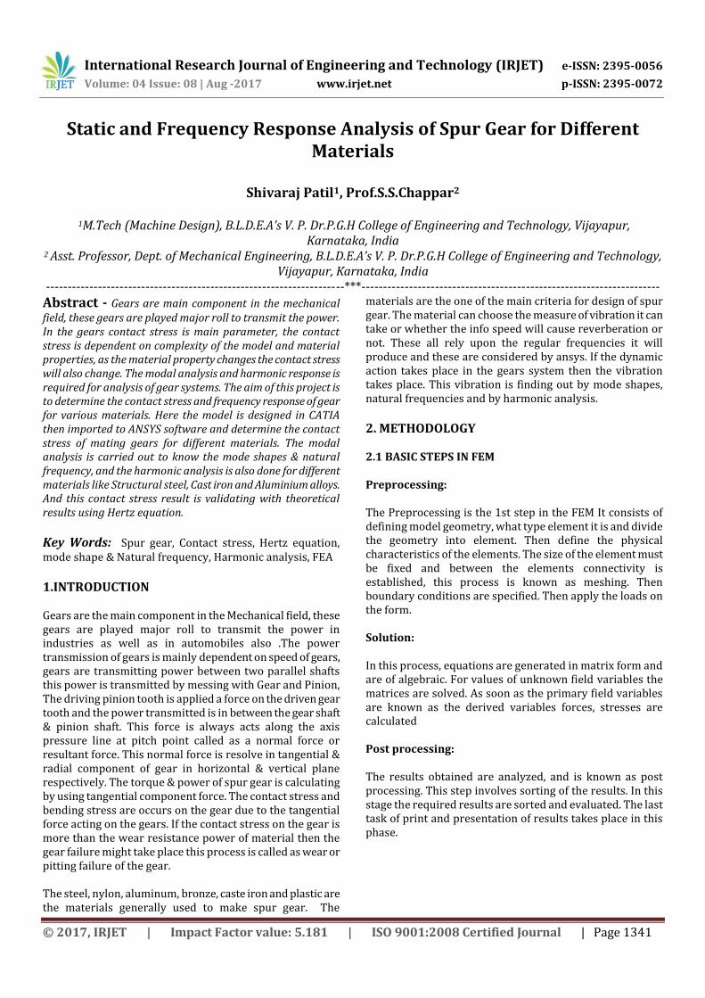
Fig 3.4 (c) mode 3
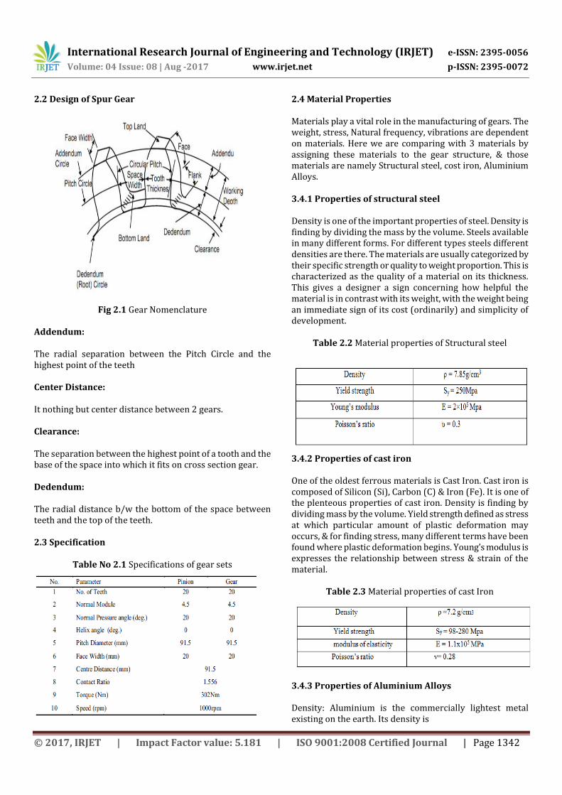
Fig 3.4 (d) mode 4
To find the vibration characteristics for linear elastic system the one technique is used that is modal analysis. From the modal analysis, we have got the 20 mode shapes with different natural frequencies; from these we have interpreted the structural behavior with mode shapes. Noise and vibration are interrelated one important factor in reducing the noise is altering the natural frequency. The above fig 3.4 (a), 3.4 (b), 3.4 (c) and 3.4 (d) shows the mode shapes and natural frequencies for structural steel material The fig 3.4 (a) shows that the natural frequency of 1471.1 Hz, and the mode shape for this frequency is in lateral direction. The fig 3.4 (b) shows that the natural frequency of 3336.5 Hz, and the mode shape for this frequency is in longitudinal direction. The fig 3.4 (c) shows that the natural frequency of 4672 Hz, and the mode shape for this frequency is in twisting mode. The fig 3.4 (d) shows that the natural frequency of 5519.3 Hz, and the mode shape for this frequency is in bending mode.
Mode shapes and natural frequency for Cast Iron
Fig 3.5 (a) mode 1
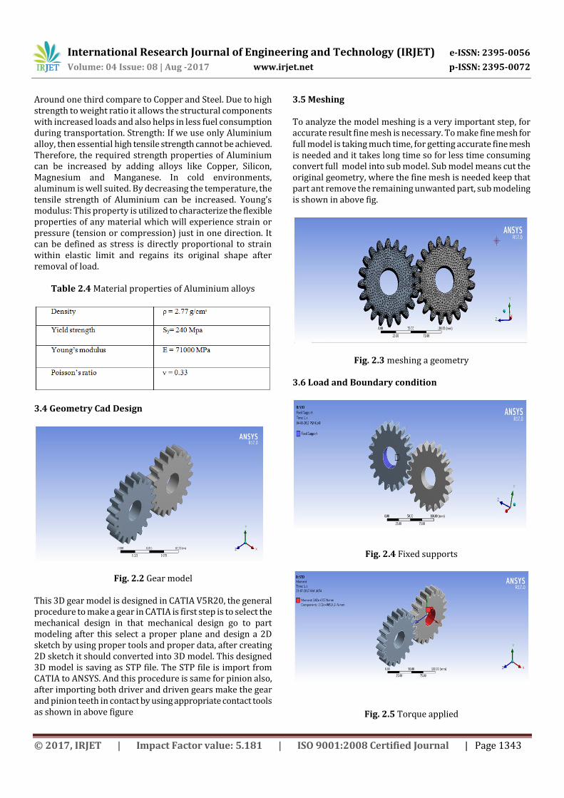
Fig 3.5 (B) mode 2
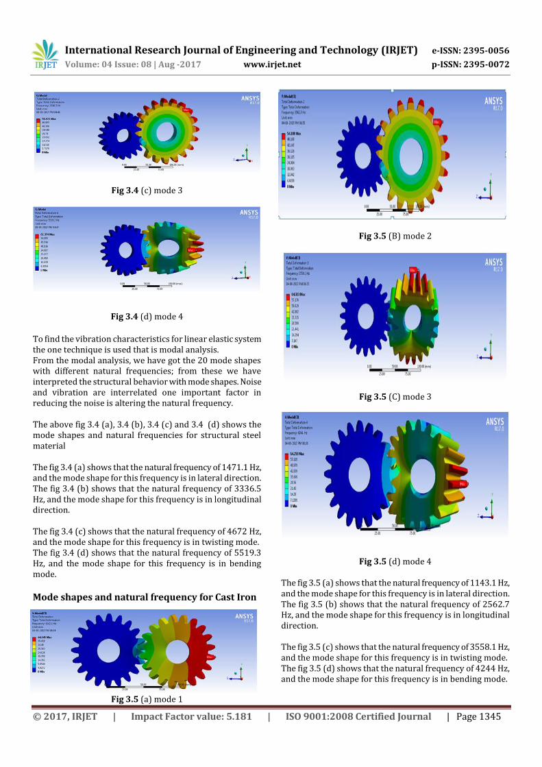
Fig 3.5 (C) mode 3
Fig 3.5 (d) mode 4 The fig 3.5 (a) shows that the natural frequency of 1143.1 Hz, and the mode shape for this frequency is in lateral direction. The fig 3.5 (b) shows that the natural frequency of 2562.7 Hz, and the mode shape for this frequency is in longitudinal direction. The fig 3.5 (c) shows that the natural frequency of 3558.1 Hz, and the mode shape for this frequency is in twisting mode. The fig 3.5 (d) shows that the natural frequency of 4244 Hz, and the mode shape for this frequency is in bending mode.
International Research Journal of Engineering and Technology (IRJET) e-ISSN: 2395-0056
Volume: 04 Issue: 08 | Aug -2017 www.irjet.net p-ISSN: 2395-0072
© 2017, IRJET | Impact Factor value: 5.181 | ISO 9001:2008 Certified Journal | Page 1346
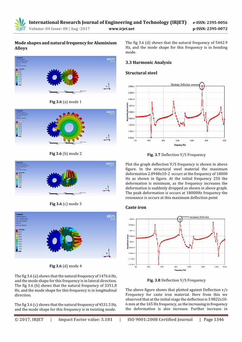
Mode shapes and natural frequency for Aluminium Alloys
Fig 3.6 (a) mode 1
Fig 3.6 (b) mode 2
Fig 3.6 (c) mode 3
Fig 3.6 (d) mode 4
The fig 3.6 (a) shows that the natural frequency of 1476.6 Hz, and the mode shape for this frequency is in lateral direction. The fig 3.6 (b) shows that the natural frequency of 3351.8 Hz, and the mode shape for this frequency is in longitudinal direction. The fig 3.6 (c) shows that the natural frequency of 4531.5 Hz, and the mode shape for this frequency is in twisting mode.
The fig 3.6 (d) shows that the natural frequency of 5442.9 Hz, and the mode shape for this frequency is in bending mode.
3.3 Harmonic Analysis Structural steel
Fig. 3.7 Deflection V/S Frequency
Plot the graph deflection V/S frequency is shown in above figure. In the structural steel material the maximum deformation 2.0948x10⁻² occurs at the frequency of 18000 Hz as shown in figure. At the initial frequency 250 the deformation is minimum, as the frequency increases the deformation is suddenly dropped as shown in above graph. The peak deformation is occurs at 18000Hz frequency the resonance is occurs at this maximum deflection point
Caste iron
Fig. 3.8 Deflection V/S Frequency
The above figure shows that plotted against Deflection v/s Frequency for caste iron material. Here from this we observed that at the initial stage the deflection is 3.9822x10⁻⁶ mm at the 165 Hz frequency, as the increasing in frequency the deformation is also increase. Further increase in
International Research Journal of Engineering and Technology (IRJET) e-ISSN: 2395-0056
Volume: 04 Issue: 08 | Aug -2017 www.irjet.net p-ISSN: 2395-0072
© 2017, IRJET | Impact Factor value: 5.181 | ISO 9001:2008 Certified Journal | Page 1347
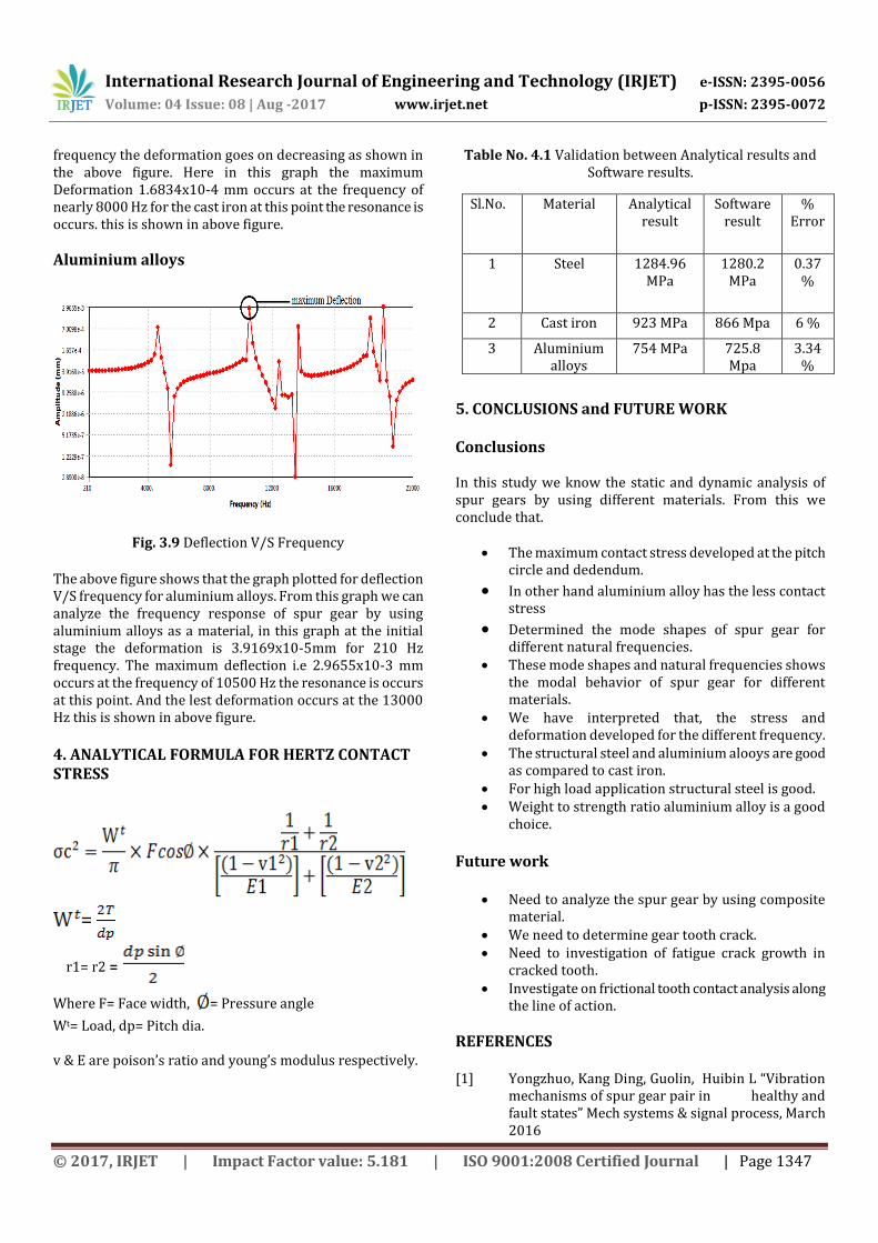
frequency the deformation goes on decreasing as shown in the above figure. Here in this graph the maximum Deformation 1.6834x10⁻⁴ mm occurs at the frequency of nearly 8000 Hz for the cast iron at this point the resonance is occurs. this is shown in above figure.
Aluminium alloys
Fig. 3.9 Deflection V/S Frequency
The above figure shows that the graph plotted for deflection V/S frequency for aluminium alloys. From this graph we can analyze the frequency response of spur gear by using aluminium alloys as a material, in this graph at the initial stage the deformation is 3.9169x10⁻⁵mm for 210 Hz frequency. The maximum deflection i.e 2.9655x10⁻³ mm occurs at the frequency of 10500 Hz the resonance is occurs at this point. And the lest deformation occurs at the 13000 Hz this is shown in above figure.
4. ANALYTICAL FORMULA FOR HERTZ CONTACT STRESS
=
r1= r2 =
Where F= Face width, = Pressure angle
Wt= Load, dp= Pitch dia. v & E are poison’s ratio and young’s modulus respectively.
Table No. 4.1 Validation between Analytical results and Software results.
5. CONCLUSIONS and FUTURE WORK Conclusions In this study we know the static and dynamic analysis of spur gears by using different materials. From this we conclude that.
The maximum contact stress developed at the pitch circle and dedendum.
In other hand aluminium alloy has the less contact stress
Determined the mode shapes of spur gear for different natural frequencies.
These mode shapes and natural frequencies shows the modal behavior of spur gear for different materials.
We have interpreted that, the stress and deformation developed for the different frequency.
The structural steel and aluminium alooys are good as compared to cast iron.
For high load application structural steel is good. Weight to strength ratio aluminium alloy is a good
choice.
Future work
Need to analyze the spur gear by using composite material.
We need to determine gear tooth crack. Need to investigation of fatigue crack growth in
cracked tooth. Investigate on frictional tooth contact analysis along
the line of action.
REFERENCES [1] Yongzhuo, Kang Ding, Guolin, Huibin L “Vibration
mechanisms of spur gear pair in healthy and fault states” Mech systems & signal process, March 2016
Sl.No. Material Analytical result
Software result
% Error
1 Steel 1284.96 MPa
1280.2 MPa
0.37 %
2 Cast iron 923 MPa 866 Mpa 6 %
3 Aluminium alloys
754 MPa 725.8 Mpa
3.34 %
International Research Journal of Engineering and Technology (IRJET) e-ISSN: 2395-0056
Volume: 04 Issue: 08 | Aug -2017 www.irjet.net p-ISSN: 2395-0072
© 2017, IRJET | Impact Factor value: 5.181 | ISO 9001:2008 Certified Journal | Page 1348
[2] Mohammad Jebran K, Arunish M, Sajad Hussain “Contact stress analysis of stainless steel spur gears using FEA method & comparing result with theoretical results with hertz theory” Int. Journal of Engineering Research and Applications, ISSN : 2248-9622, Vol. 5, Issue 4, ( Part -5), April 2015
[3] Santosh P, Saravanan K, I Atanasovska, Azmi Wahab “Frictional tooth contact analysis along line of action of spur gear using finite element method” AMME 2014
[4] Seok Hwang, Hwan Lee, Dong-Hyung , Seung-H Hana, Kwon-Hee “Contact analysis for a pair of mating gears” Mathematical & Computer modeling 57(2013) 40-49, June 2011
[5] Padmanaban. S, Ganesan. S, Chandrasekaran. M, Srinivansan Raman “Gear pair design IEEE 2010
[6] Yangyang, Yunxia, Kan rui, Jiyu “Analysis of dynamic contact mechanical response & contact life of low speed spur gear” IEEE 2015
[7] Putti Srinivasa, Nadipalli S, M Farookh “Contact Stress Analysis of Spur Gear for Different Materials using ANSYS and Hertz Equation” IJMSME Volume 1, Issue 1, June 2015