magnetically levitated trains (maglev) · international research journal of engineering and...
TRANSCRIPT
International Research Journal of Engineering and Technology (IRJET) e-ISSN: 2395 -0056
Volume: 04 Issue: 04 | Apr -2017 www.irjet.net p-ISSN: 2395-0072
© 2017, IRJET | Impact Factor value: 5.181 | ISO 9001:2008 Certified Journal | Page 1274
DEDICATED TO CRR/MINISTRY OF RAILWAYS/INDIAN RAILWAYS/RDSO
Magnetically Levitated Trains (Maglev)
Shripad Shashikant Chopade, M Tech (Machine Design & Robotics), UPSC (IES) IRSME (R&D), Government of India, Ph.D Research Scholar, India
---------------------------------------------------------------------------------------------------------------------------------
Abstract: Magnetic Leviated Trains system represent a promising evolution in the high-speed ground
transportation offering speeds in excess of 500-600 mph along with the potential for low operating costs and
minimum environmental impact. The goal of this effort is to investigate the feasibility and viability of maglev
systems in the Japan. The emergence of a sophisticated technology such as maglev requires a need for a
coordinated research test program and the determination of test requirements to identify and mitigate
development risk and to maximum use of domestic resources.
The study is directed toward the identification and characterization of maglev systems development risks tied to preliminary system architecture. Research objectives are accomplished by surveying experiences from previous maglev development programs both foreign, domestic and interviews with individuals involved with maglev research and testing. Planning and implementation requirements are identified for a maglev test program, including the development of a facilities strategy to meet any operational concept that evolves out of early development effort. Also specified is the logical development flow and associated long-lead support needs for sub-scale and full-scale testing.
Keywords: Beam, Propulsion Coil, Track, Levitations and Guidance Coil, Magnets and Magnetic Coil, Magnet Trains, N-S Poles, Super Conducting Magnet.
INTRODUCTION
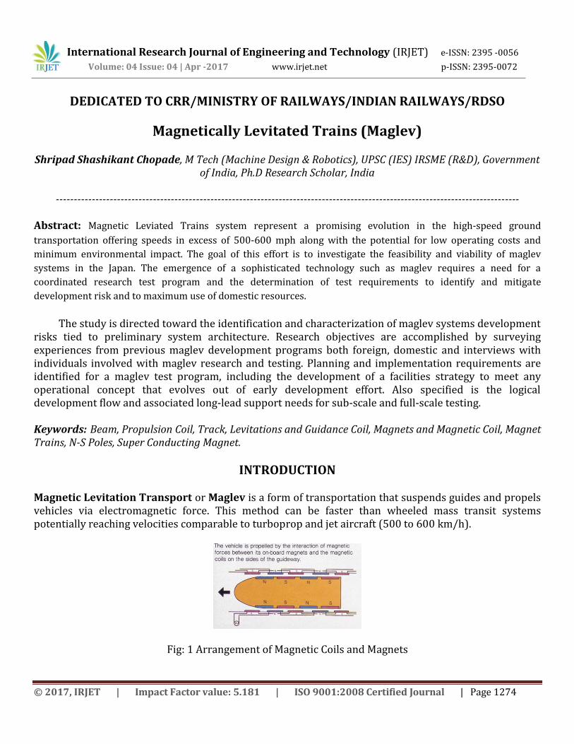
Magnetic Levitation Transport or Maglev is a form of transportation that suspends guides and propels vehicles via electromagnetic force. This method can be faster than wheeled mass transit systems potentially reaching velocities comparable to turboprop and jet aircraft (500 to 600 km/h).
Fig: 1 Arrangement of Magnetic Coils and Magnets
International Research Journal of Engineering and Technology (IRJET) e-ISSN: 2395 -0056
Volume: 04 Issue: 04 | Apr -2017 www.irjet.net p-ISSN: 2395-0072
© 2017, IRJET | Impact Factor value: 5.181 | ISO 9001:2008 Certified Journal | Page 1275
All operational implementations of maglev technology have had minimum overlap with wheeled train technology and have not been compatible with conventional railroad tracks. Because they cannot share existing infrastructure, maglev must be designed as complete transportation systems. The term "maglev" refers not only to the vehicles but to the railway system as well, specifically designed for magnetic levitation and propulsion.
Magnetically Levitated Trains
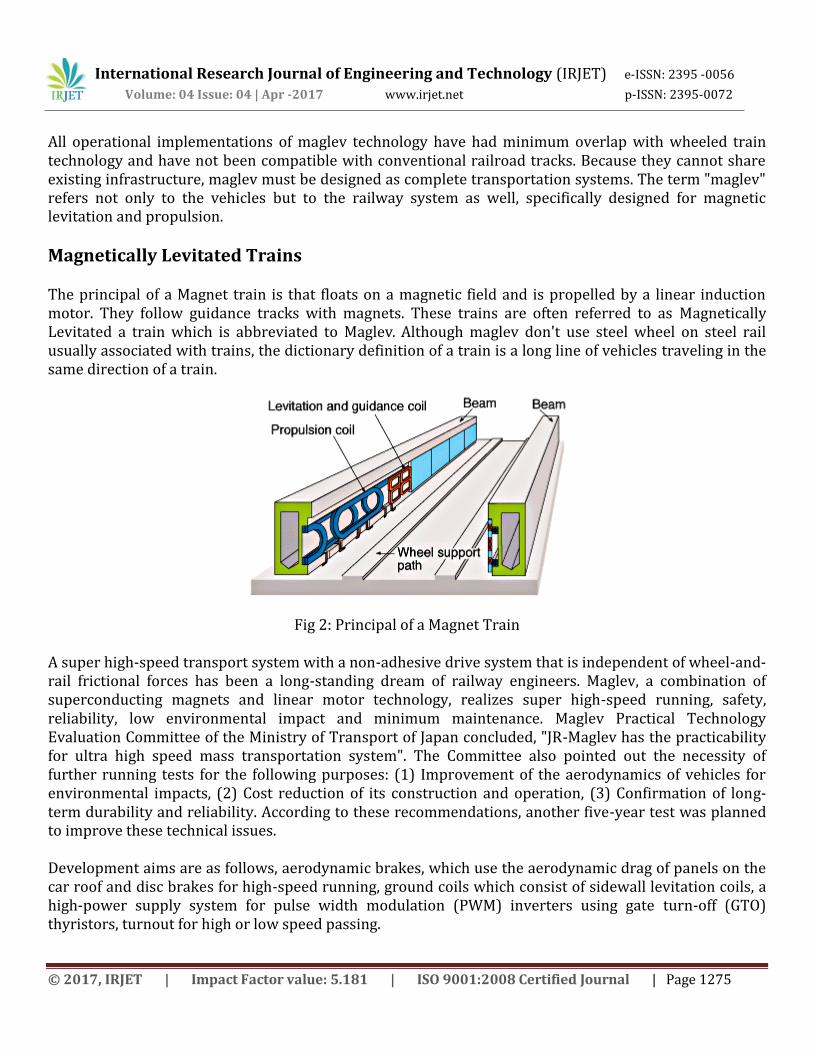
The principal of a Magnet train is that floats on a magnetic field and is propelled by a linear induction motor. They follow guidance tracks with magnets. These trains are often referred to as Magnetically Levitated a train which is abbreviated to Maglev. Although maglev don't use steel wheel on steel rail usually associated with trains, the dictionary definition of a train is a long line of vehicles traveling in the same direction of a train.
Fig 2: Principal of a Magnet Train
A super high-speed transport system with a non-adhesive drive system that is independent of wheel-and-rail frictional forces has been a long-standing dream of railway engineers. Maglev, a combination of superconducting magnets and linear motor technology, realizes super high-speed running, safety, reliability, low environmental impact and minimum maintenance. Maglev Practical Technology Evaluation Committee of the Ministry of Transport of Japan concluded, "JR-Maglev has the practicability for ultra high speed mass transportation system". The Committee also pointed out the necessity of further running tests for the following purposes: (1) Improvement of the aerodynamics of vehicles for environmental impacts, (2) Cost reduction of its construction and operation, (3) Confirmation of long-term durability and reliability. According to these recommendations, another five-year test was planned to improve these technical issues.
Development aims are as follows, aerodynamic brakes, which use the aerodynamic drag of panels on the car roof and disc brakes for high-speed running, ground coils which consist of sidewall levitation coils, a high-power supply system for pulse width modulation (PWM) inverters using gate turn-off (GTO) thyristors, turnout for high or low speed passing.
International Research Journal of Engineering and Technology (IRJET) e-ISSN: 2395 -0056
Volume: 04 Issue: 04 | Apr -2017 www.irjet.net p-ISSN: 2395-0072
© 2017, IRJET | Impact Factor value: 5.181 | ISO 9001:2008 Certified Journal | Page 1276
One main development aim of RTRI is the enhancement of reliability and durability of the super conducting magnet (SCM). The SCM suffers from external magnetic disturbances caused by ground coils and from mechanical vibrations generated by vehicle dynamics, these disturbances cause quenching troubles or the sudden disappearance of magneto motive force of the SCM. We have studied these problems through many tests and studies and have developed countermeasures.
Technology & Working of Maglev
There are two primary types of Maglev Technology
Electrodynamics suspension (EDS) uses a repulsive force between two magnetic fields to push the train away from the rail.
Electromagnetic suspension (EMS) uses the attractive magnetic force of a magnet beneath a rail to lift the train up.
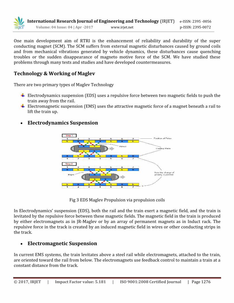
Electrodynamics Suspension
Fig 3 EDS Maglev Propulsion via propulsion coils
In Electrodynamics’ suspension (EDS), both the rail and the train exert a magnetic field, and the train is levitated by the repulsive force between these magnetic fields. The magnetic field in the train is produced by either electromagnets as in JR-Maglev or by an array of permanent magnets as in Induct rack. The repulsive force in the track is created by an induced magnetic field in wires or other conducting strips in the track.
Electromagnetic Suspension
In current EMS systems, the train levitates above a steel rail while electromagnets, attached to the train, are oriented toward the rail from below. The electromagnets use feedback control to maintain a train at a constant distance from the track.
International Research Journal of Engineering and Technology (IRJET) e-ISSN: 2395 -0056
Volume: 04 Issue: 04 | Apr -2017 www.irjet.net p-ISSN: 2395-0072
© 2017, IRJET | Impact Factor value: 5.181 | ISO 9001:2008 Certified Journal | Page 1277
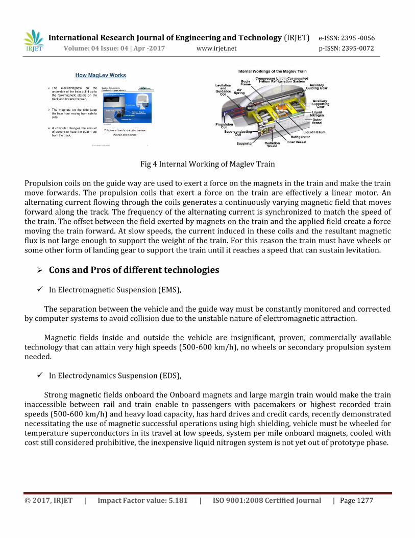
Fig 4 Internal Working of Maglev Train
Propulsion coils on the guide way are used to exert a force on the magnets in the train and make the train move forwards. The propulsion coils that exert a force on the train are effectively a linear motor. An alternating current flowing through the coils generates a continuously varying magnetic field that moves forward along the track. The frequency of the alternating current is synchronized to match the speed of the train. The offset between the field exerted by magnets on the train and the applied field create a force moving the train forward. At slow speeds, the current induced in these coils and the resultant magnetic flux is not large enough to support the weight of the train. For this reason the train must have wheels or some other form of landing gear to support the train until it reaches a speed that can sustain levitation.
Cons and Pros of different technologies
In Electromagnetic Suspension (EMS),
The separation between the vehicle and the guide way must be constantly monitored and corrected by computer systems to avoid collision due to the unstable nature of electromagnetic attraction.
Magnetic fields inside and outside the vehicle are insignificant, proven, commercially available technology that can attain very high speeds (500-600 km/h), no wheels or secondary propulsion system needed.
In Electrodynamics Suspension (EDS),
Strong magnetic fields onboard the Onboard magnets and large margin train would make the train inaccessible between rail and train enable to passengers with pacemakers or highest recorded train speeds (500-600 km/h) and heavy load capacity, has hard drives and credit cards, recently demonstrated necessitating the use of magnetic successful operations using high shielding, vehicle must be wheeled for temperature superconductors in its travel at low speeds, system per mile onboard magnets, cooled with cost still considered prohibitive, the inexpensive liquid nitrogen system is not yet out of prototype phase.
International Research Journal of Engineering and Technology (IRJET) e-ISSN: 2395 -0056
Volume: 04 Issue: 04 | Apr -2017 www.irjet.net p-ISSN: 2395-0072
© 2017, IRJET | Impact Factor value: 5.181 | ISO 9001:2008 Certified Journal | Page 1278
Induct rack System (Permanent Magnet EDS)
Failsafe Suspension no power required to requires either wheels or track activate magnets, Magnetic field is segments that move for when localized below the car, can generate the vehicle is stopped. New enough force at low speeds to levitate maglev train, in case of development power failure cars slow down on their own has as yet no commercial in a safe, steady and predictable manner version or full scale system before coming to a stop, Halbach arrays of prototype. Permanent magnets may prove more cost-effective than electromagnets.
Propulsion
An EMS system can provide both levitation and propulsion using an onboard linear motor. EDS systems can only levitate the train using the magnets onboard, not propel it forward. As such, vehicles need some other technology for propulsion. A linear motor (propulsion coils) mounted in the track is one solution. Over long distances where the cost of propulsion coils could be prohibitive, a propeller or jet engine could be used.
Stability
Static magnetic bearings using only electromagnets and per magnets are unstable, as explained by Earnshaw's theorem. EMS systems rely on active electronic stabilization. Such systems constantly measure the bearing distance and adjust the electromagnet current accordingly. As all EDS systems are moving systems (i.e. no EDS system can levitate the train unless it is in motion), Earnshaw's theorem does not apply to them.
Pros and Cons of Maglev vs. Conventional Trains
Due to the lack of physical contact between the track and the vehicle, there is no rolling friction, leaving only air resistance (although maglev trains also experience electromagnetic drag, this is relatively small at high speeds).
Maglev can handle high volumes of passengers per hour (comparable to airports or eight-lane highways) and do it without introducing air pollution along the right of way. Of course, the electricity has to be generated somewhere, so the overall environmental impact of a maglev system is dependent on the nature of the grid power source.
The weight of the large electromagnets in EMS and EDS designs are a major design issue. A very strong magnetic field is required to levitate a massive train. For this reason one research path is using superconductors to improve the efficiency of the electromagnets.
Due to its high speed and shape, the noise generated by a maglev train is similar to a jet aircraft and is considerably more disturbing than standard steel on steel intercity train noise. A study found the difference between disturbance levels of maglev and traditional trains to be 5dB about 78% noisier.
International Research Journal of Engineering and Technology (IRJET) e-ISSN: 2395 -0056
Volume: 04 Issue: 04 | Apr -2017 www.irjet.net p-ISSN: 2395-0072
© 2017, IRJET | Impact Factor value: 5.181 | ISO 9001:2008 Certified Journal | Page 1279
Super Conducting Magnet of the Maglev Test Line
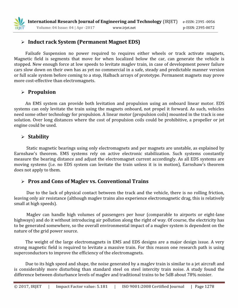
Fig 5 Super Conducting Magnet of the Maglev Test Line
The SCM (Super Conducting Magnet) is the core element of super conducting Maglev. Two SCMs are mounted on each bogie. Each SCM of the Maglev Test Line consists of 4 SC coils. The SCM features high reliability and high durability, embodying the achievements of the Maglev Test Track and RTRI. The cylindrical unit at the top is a tank holding liquefied helium and nitrogen. The bottom unit is an SC coil alternately generating N poles and S poles. At one end of the tank is the integrally-attached on-board refrigerator, which serves to re-liquefy the helium gas once, vaporized by regular heat absorption and external disturbances during running.
Fig 6 Super Conducting Magnet of the Maglev Test Line (Cut Model)
International Research Journal of Engineering and Technology (IRJET) e-ISSN: 2395 -0056
Volume: 04 Issue: 04 | Apr -2017 www.irjet.net p-ISSN: 2395-0072
© 2017, IRJET | Impact Factor value: 5.181 | ISO 9001:2008 Certified Journal | Page 1280
Electrical Facilities of the Maglev Test Line
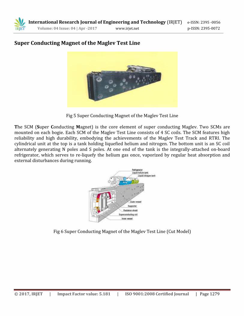
Fig 7 External view of the inverter unit
The inverter installed at the substation for power conversion is a facility to transform the power supplied from the utility company at commercial frequency into one of a frequency required for train operation. The operation control system at the test center formulates run curves, which in turn instruct the drive control system at the substation for power conversion.
Boarding Facilities of the Maglev Test Line
In the Maglev operation, for the purpose of shielding the passengers from the magnetic fields of the SCMs, boarding facilities resembling boarding bridges at airports are installed on the platform so that the passengers can safely get on or off the train.
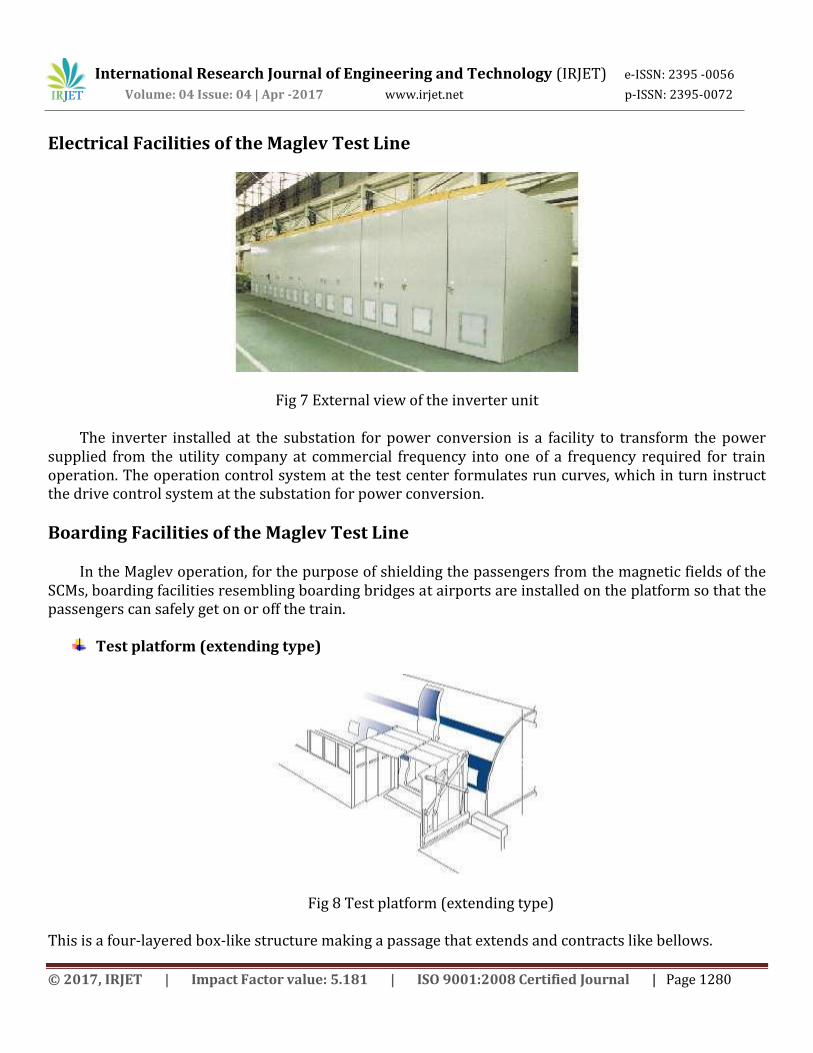
Test platform (extending type)
Fig 8 Test platform (extending type)
This is a four-layered box-like structure making a passage that extends and contracts like bellows.
International Research Journal of Engineering and Technology (IRJET) e-ISSN: 2395 -0056
Volume: 04 Issue: 04 | Apr -2017 www.irjet.net p-ISSN: 2395-0072
© 2017, IRJET | Impact Factor value: 5.181 | ISO 9001:2008 Certified Journal | Page 1281
Test platform (rotating type)
Fig 9 Test platform (rotating type)
This is a three-sided structure consisting of a floor and two sidewalls. For boarding, pair of doors on the platform side rotates 90 degrees and sliding boards emerge, making a passage.
Guideway of the Maglev Test Line
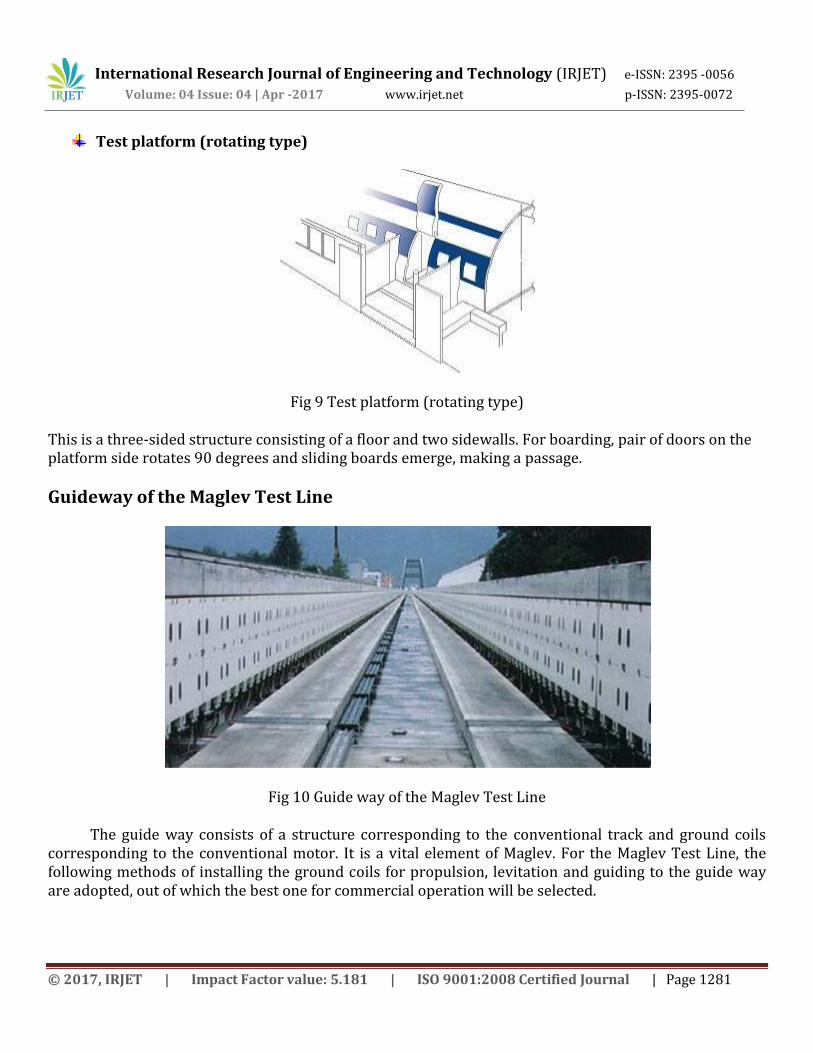
Fig 10 Guide way of the Maglev Test Line
The guide way consists of a structure corresponding to the conventional track and ground coils corresponding to the conventional motor. It is a vital element of Maglev. For the Maglev Test Line, the following methods of installing the ground coils for propulsion, levitation and guiding to the guide way are adopted, out of which the best one for commercial operation will be selected.
International Research Journal of Engineering and Technology (IRJET) e-ISSN: 2395 -0056
Volume: 04 Issue: 04 | Apr -2017 www.irjet.net p-ISSN: 2395-0072
© 2017, IRJET | Impact Factor value: 5.181 | ISO 9001:2008 Certified Journal | Page 1282
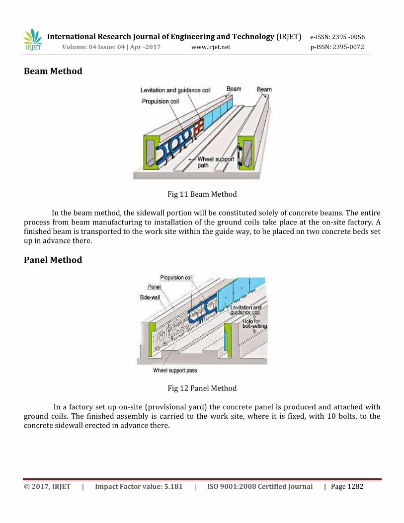
Beam Method
Fig 11 Beam Method
In the beam method, the sidewall portion will be constituted solely of concrete beams. The entire process from beam manufacturing to installation of the ground coils take place at the on-site factory. A finished beam is transported to the work site within the guide way, to be placed on two concrete beds set up in advance there.
Panel Method
Fig 12 Panel Method
In a factory set up on-site (provisional yard) the concrete panel is produced and attached with ground coils. The finished assembly is carried to the work site, where it is fixed, with 10 bolts, to the concrete sidewall erected in advance there.
International Research Journal of Engineering and Technology (IRJET) e-ISSN: 2395 -0056
Volume: 04 Issue: 04 | Apr -2017 www.irjet.net p-ISSN: 2395-0072
© 2017, IRJET | Impact Factor value: 5.181 | ISO 9001:2008 Certified Journal | Page 1283
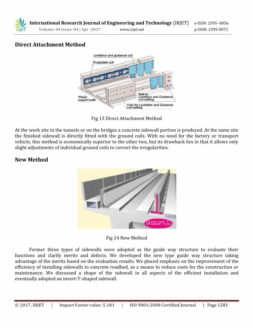
Direct Attachment Method
Fig 13 Direct Attachment Method
At the work site in the tunnels or on the bridges a concrete sidewall portion is produced. At the same site the finished sidewall is directly fitted with the ground coils. With no need for the factory or transport vehicle, this method is economically superior to the other two, but its drawback lies in that it allows only slight adjustments of individual ground coils to correct the irregularities.
New Method
Fig 14 New Method
Former three types of sidewalls were adopted as the guide way structure to evaluate their functions and clarify merits and defects. We developed the new type guide way structure taking advantage of the merits based on the evaluation results. We placed emphasis on the improvement of the efficiency of installing sidewalls to concrete roadbed, as a means to reduce costs for the construction or maintenance. We discussed a shape of the sidewall in all aspects of the efficient installation and eventually adopted an invert-T-shaped sidewall.
International Research Journal of Engineering and Technology (IRJET) e-ISSN: 2395 -0056
Volume: 04 Issue: 04 | Apr -2017 www.irjet.net p-ISSN: 2395-0072
© 2017, IRJET | Impact Factor value: 5.181 | ISO 9001:2008 Certified Journal | Page 1284
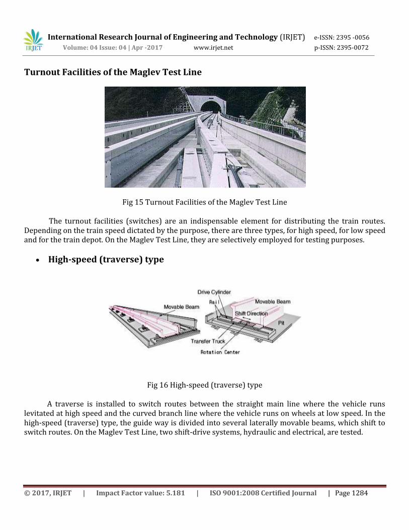
Turnout Facilities of the Maglev Test Line
Fig 15 Turnout Facilities of the Maglev Test Line
The turnout facilities (switches) are an indispensable element for distributing the train routes. Depending on the train speed dictated by the purpose, there are three types, for high speed, for low speed and for the train depot. On the Maglev Test Line, they are selectively employed for testing purposes.
High-speed (traverse) type
Fig 16 High-speed (traverse) type
A traverse is installed to switch routes between the straight main line where the vehicle runs levitated at high speed and the curved branch line where the vehicle runs on wheels at low speed. In the high-speed (traverse) type, the guide way is divided into several laterally movable beams, which shift to switch routes. On the Maglev Test Line, two shift-drive systems, hydraulic and electrical, are tested.
International Research Journal of Engineering and Technology (IRJET) e-ISSN: 2395 -0056
Volume: 04 Issue: 04 | Apr -2017 www.irjet.net p-ISSN: 2395-0072
© 2017, IRJET | Impact Factor value: 5.181 | ISO 9001:2008 Certified Journal | Page 1285
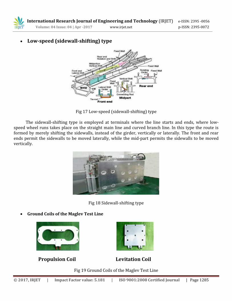
Low-speed (sidewall-shifting) type
Fig 17 Low-speed (sidewall-shifting) type
The sidewall-shifting type is employed at terminals where the line starts and ends, where low-speed wheel runs takes place on the straight main line and curved branch line. In this type the route is formed by merely shifting the sidewalls, instead of the girder, vertically or laterally. The front and rear ends permit the sidewalls to be moved laterally, while the mid-part permits the sidewalls to be moved vertically.
Fig 18 Sidewall-shifting type
Ground Coils of the Maglev Test Line
Propulsion Coil Levitation Coil
Fig 19 Ground Coils of the Maglev Test Line
International Research Journal of Engineering and Technology (IRJET) e-ISSN: 2395 -0056
Volume: 04 Issue: 04 | Apr -2017 www.irjet.net p-ISSN: 2395-0072
© 2017, IRJET | Impact Factor value: 5.181 | ISO 9001:2008 Certified Journal | Page 1286
For the superconducting LSM (Linear Synchronous Motor), the ground coil is an essential element corresponding to the armature in the conventional motor and to the conventional rails. The ground coils come in two types, propulsion coils to propel the vehicle and levitation coils serving both to levitate the vehicle and to guide it laterally. When electric current flows in these coils fitted to the guide way, the Maglev vehicle can run.
On the Maglev Test Line, the propulsion coils are arranged in two overlapping layers to reduce the external electromagnetic disturbances influencing the Superconducting Magnet, the levitation coils are placed on these propulsion coils. Both the propulsion coils and the levitation coils are wound aluminum conductors and molded with resin. The propulsion coils are required to be electrically insulated and mechanically strong, while the levitation coils are required mainly to be mechanically strong. Therefore the propulsion coils are moldings of epoxy resin, while the levitation coils are moldings of unsaturated polyester resin respectively reinforced with glass fiber. Advantages of Maglev
The main advantage is that because maglev trains float, there is no friction that there will still be air resistance.
The second advantage is maintenance. Because the train floats along there is no contact with the ground and therefore no need for any moving parts. As a result there are no components that would wear out. This means in theory trains and track would need no maintenance at all.
Less noise, because there are no wheels running along there is no wheel noise. However noise due to air disturbance still occurs.
No engine that is no fuel required. The final advantage is speed, as a result of the three previous listed it is more viable for maglev
trains to travel extremely fast, i.e. 500km/h or 300mph. Although this is possible with conventional rail it is not economically viable.
Greater gradients would be applicable.
Disadvantages with Maglev
Lack with existing infrastructure. Maglev guide paths are bound to be more costly than conventional steel railways.
CONCLUSION
Future of Maglev holds an undisputed demand level at the global level.
Maglev may become the preferred path for new high speed railway lines although it would depend whether or not services were needed to stretch beyond a high speed line.
International Research Journal of Engineering and Technology (IRJET) e-ISSN: 2395 -0056
Volume: 04 Issue: 04 | Apr -2017 www.irjet.net p-ISSN: 2395-0072
© 2017, IRJET | Impact Factor value: 5.181 | ISO 9001:2008 Certified Journal | Page 1287
ACKNOWLEDGMENT
I Deeply Express My Hearty Gratitude and Thanks to International Research Journal of Engineering and Technology.
REFERENCES
[1] Japanese Technical Research Institute- Japanese projects
[2] www.chron.com
[3] en.wikipedia.org
[4] www.dbamanufacturing.com
[5] www.ieee.com
[6] www.singnet.com.sg
[7] news.bbc.co.uk
[8] The Official Transrapid Site- lots of information about Maglev.
BIOGRAPHIES
My Name is Shripad Shashikant Chopade, Working in Indian Railways,
Researcher on Maglev Train (R&D), Government of India, Ministry of
Railways. Dedicated to Ministry of Railways / Indian Railways / RDSO.