springer handbook of nanotechnology: chapter 3
TRANSCRIPT
39
Introduction t3. Introduction to Carbon Nanotubes
Carbon nanotubes are among the amazingobjects that science sometimes creates byaccident, without meaning to, but that willlikely revolutionize the technological landscapeof the century ahead. Our society stands to besignificantly influenced by carbon nanotubes,shaped by nanotube applications in every aspect,just as silicon-based technology still shapessociety today. The world already dreams of space-elevators tethered by the strongest of cables,hydrogen-powered vehicles, artificial muscles,and so on – feasts that would be made possibleby the emerging carbon nanotube science.
Of course, nothing is set in stone yet. We arestill at the stage of possibilities and potential. Therecent example of fullerenes – molecules closelyrelated to nanotubes, whose importance was soanticipated that their discovery in 1985 broughta Nobel Prize to their finders in 1996 althoughfew related applications have actually yet reachedthe market – teaches us to play the game ofenthusiastic predictions with some caution. Butin the case of carbon nanotubes, expectations arehigh. Taking again the example of electronics,the miniaturization of chips is about to reach itslowest limits. Are we going to accept that ourvideo camera, computers, and cellular phones nolonger decrease in size and increase in memoryevery six months? Surely not. Always going deeper,farther, smaller, higher is a characteristic uniqueto humankind, and which helps to explain itsdomination of the living world on earth. Carbonnanotubes can help us fulfill our expectation ofconstant technological progress as a source ofbetter living.
In this chapter, after the structure, synthesismethods, growth mechanisms, and properties ofcarbon nanotubes will be described, an entiresection will be devoted to nanotube-relatednano-objects. Indeed, should pristine nanotubesreach any limitation in some area, their ready andclose association to foreign atoms, molecules,
3.1 Structure of Carbon Nanotubes .............. 403.1.1 Single-Wall Nanotubes ................. 403.1.2 Multiwall Nanotubes .................... 43
3.2 Synthesis of Carbon Nanotubes .............. 453.2.1 Solid Carbon Source-Based
Production Techniquesfor Carbon Nanotubes ................... 45
3.2.2 Gaseous Carbon Source-BasedProduction Techniquesfor Carbon Nanotubes ................... 52
3.2.3 Miscellaneous Techniques ............. 573.2.4 Synthesis
of Aligned Carbon Nanotubes ........ 58
3.3 Growth Mechanisms of Carbon Nanotubes 593.3.1 Catalyst-Free Growth .................... 593.3.2 Catalytically Activated Growth ........ 60
3.4 Properties of Carbon Nanotubes ............. 633.4.1 Variability of Carbon Nanotube
Properties ................................... 633.4.2 General Properties ....................... 633.4.3 SWNT Adsorption Properties ........... 633.4.4 Transport Properties ..................... 653.4.5 Mechanical Properties................... 673.4.6 Reactivity .................................... 67
3.5 Carbon Nanotube-Based Nano-Objects ... 683.5.1 Hetero-Nanotubes ....................... 683.5.2 Hybrid Carbon Nanotubes.............. 683.5.3 Functionalized Nanotubes ............. 71
3.6 Applications of Carbon Nanotubes.......... 733.6.1 Current Applications ..................... 733.6.2 Expected Applications
Related to Adsorption ................... 76
References .................................................. 86
and compounds offers the prospect of an evenmagnified set of properties. Finally, we willdescribe carbon nanotube applications supportingthe idea that the future for the science andtechnology of carbon nanotubes looks verypromising.
PartA
3
40 Part A Nanostructures, Micro/Nanofabrication, and Micro/Nanodevices
Carbon nanotubes have been synthesized for a long timeas products from the action of a catalyst over the gaseousspecies originating from the thermal decomposition ofhydrocarbons (see Sect. 3.2). Some of the first evidencethat the nanofilaments thus produced were actually nano-tubes – i. e., exhibiting an inner cavity – can be foundin the transmission electron microscope micrographspublished by Hillert et al. in 1958 [3.1]. This was ofcourse related to and made possible by the progress intransmission electron microscopy. It is then likely thatthe carbon filaments prepared by Hughes and Cham-bers in 1889 [3.2], reported by Maruyama et al. [3.3] asprobably the first patent ever deposited in the field, andwhose preparation method was also based on the cata-lytically enhanced thermal cracking of hydrocarbons,were already carbon nanotube-related morphologies.The preparation of vapor-grown carbon fibers had ac-tually been reported as early as more than one centuryago [3.4, 5]. Since then, the interest in carbon nano-filaments/nanotubes has been recurrent, though withina scientific area almost limited to the carbon materialscientist community. The reader is invited to consult thereview published by Baker et al. [3.6] regarding the earlyworks. The worldwide enthusiasm came unexpectedlyin 1991, after the catalyst-free formation of nearly per-fect concentric multiwall carbon nanotubes (c-MWNTs,see Sect. 3.1) was reported [3.7] as by-products of theformation of fullerenes by the electric-arc technique. Butthe real breakthrough occurred two years later, when at-tempts in situ to fill the nanotubes with various metals
(see Sect. 3.5) led to the discovery – again unexpected– of single-wall carbon nanotubes (SWNTs) simulta-neously by Iijima et al. [3.8] and Bethune et al. [3.9].Single-wall carbon nanotubes were really new nano-objects many of whose properties and behaviors are quitespecific (see Sect. 3.4). They are also beautiful objectsfor fundamental physics as well as unique moleculesfor experimental chemistry, still keeping some mys-tery since their formation mechanisms are a subjectof controversy and are still debated (see Sect. 3.3). Po-tential applications seem countless, although few havereached a marketable status so far (see Sect. 3.6). Conse-quently, about five papers a day with carbon nanotubesas the main topic are currently published by researchteams from around the world, an illustration of howextraordinarily active – and highly competitive – isthis field of research. It is a quite unusual situation,similar to that of fullerenes, which, by the way, areagain carbon nano-objects structurally closely relatedto nanotubes.
This is not, however, only about scientific exaltation.Economical aspects are leading the game to a greater andgreater extent. According to experts, the world market ispredicted to be more than 430 M $ in 2004 and estimatedto grow to several b $ before 2009. That is serious busi-ness, and it will be closely related to how scientists andengineers will be able to deal with the many challengesfound on the path from the beautiful, ideal moleculeto the reliable – and it is hoped, cheap – manufacturedproduct.
3.1 Structure of Carbon Nanotubes
It is simple to imagine a single-wall carbon nanotube(SWNT). Ideally, it is enough to consider a perfectgraphene sheet (a graphene being the same polyaro-matic mono-atomic layer made of an hexagonal displayof sp2 hybridized carbon atoms that genuine graphite isbuilt up with), to roll it into a cylinder (Fig. 3.1) pay-ing attention that the hexagonal rings put in contact joincoherently, then to close the tips by two caps, each capbeing a hemi-fullerene with the appropriate diameter(Fig. 3.2a–c).
3.1.1 Single-Wall Nanotubes
Geometrically, there is no restriction regarding thetube diameter. But calculations have shown that col-
lapsing the single-wall tube into a flattened two-layerribbon is energetically more favorable than maintain-ing the tubular morphology beyond a diameter value of∼ 2.5 nm [3.10]. On the other hand, it intuitively comesto mind that the shorter the radius of curvature, the higherthe stress and the energetic cost, although SWNTs withdiameters as low as 0.4 nm have been successfully syn-thesized [3.11]. A suitable energetic compromise is thusreached for ∼ 1.4 nm, the most frequent diameter en-countered regardless of the synthesis techniques (at leastthose based on solid carbon source) when conditions forhigh SWNT yields are used. There is no such restrictionfor nanotube length, which only depends on limita-tions brought by the preparation method and the specificconditions used for the synthesis (thermal gradients, res-
PartA
3.1
Introduction to Carbon Nanotubes 3.1 Structure of Carbon Nanotubes 41
y
x
θ
a1
a2
Ch
A
T
O
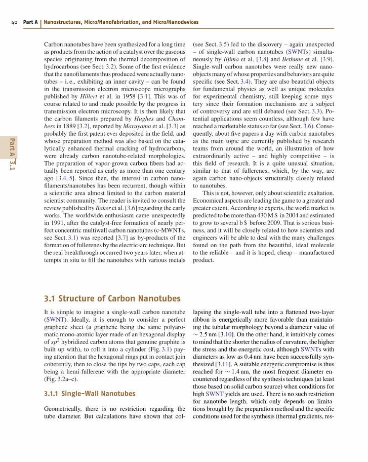
Fig. 3.1 Sketch of the way to make a single-wall car-bon nanotube, starting from a graphene sheet (adaptedfrom [3.12])
a)
b)
c)
Fig. 3.2a–c Sketch of three different SWNT structures asexamples for (a) a zig-zag-type nanotube, (b) an armchair-type nanotube, (c) a helical nanotube (adapted from [3.13])
idence time, etc.). Experimental data are consistent withthese statements, since SWNTs wider than 2.5 nm arescarcely reported in literature, whatever the preparationmethod, while SWNT length can be in the micrometeror the millimeter range. These features make single-wallcarbon nanotubes a unique example of single moleculeswith huge aspect ratios.
Two important consequences derive from the SWNTstructure as described above:
1. All carbon atoms are involved in hexagonal aromaticrings only and are therefore in equivalent position,except at the nanotube tips where 6 × 5 = 30 atomsat each tip are involved in pentagonal rings (consid-ering that adjacent pentagons are unlikely) – thoughnot more, not less, as a consequence of the Euler’srule that also governs the fullerene structure. In caseSWNTs are ideally perfect, their chemical reactiv-ity will therefore be highly favored at the tube tips,at the very location of the pentagonal rings.
2. Though carbon atoms are involved in aromatic rings,the C=C bond angles are no longer planar as theyshould ideally be. This means that the hybridizationof carbon atoms are no longer pure sp2 but get somepercentage of the sp3 character, in a proportion thatincreases as the tube radius of curvature decreases.For example, the effect is the same as for the C60fullerene molecules, whose radius of curvature is0.35 nm, and the subsequent sp3 character propor-tion about 30%. On the one hand, this is supposed tomake the SWNT surface (though consisting of aro-matic ring faces) a bit more reactive than regular,planar graphene, relatively speaking. On the otherhand, this somehow induces a variable overlappingof the bands of density of states, thereby inducinga unique versatile electronic behavior (see Sect. 3.4).
As illustrated by Fig. 3.2, there are many ways toroll a graphene into a single-wall nanotube, some ofthe resulting nanotubes enabling symmetry mirrors bothparallel and perpendicular to the nanotube axis (suchas the SWNTs from Fig. 3.2a and 3.2b), some othersnot (such as the SWNT from Fig. 3.2c). By correspon-dence with the terms used for molecules, the latter arecommonly called “chiral” nanotubes. “Helical” shouldbe preferred, however, in order to respect the definitionof chirality, which makes all chiral molecules unable tobe superimposed on their own image in a mirror. Thevarious ways to roll graphene into tubes are thereforemathematically defined by the vector of helicity Ch, andthe angle of helicity θ, as follows (referring to Fig. 3.1):
OA = Ch = na1 +ma2
with
a1 = a√
3
2x+ a
2y and a2 = a
√3
2x− a
2y
where a = 2.46 Å
and
cos θ = 2n +m
2√
n2 +m2 +nm
PartA
3.1
42 Part A Nanostructures, Micro/Nanofabrication, and Micro/Nanodevices
where n and m are the integers of the vector OA consid-ering the unit vectors a1 and a2.
The vector of helicity Ch(= OA) is perpendicular tothe tube axis, while the angle of helicity θ is taken withrespect to the so-called zig-zag axis, i. e., the vector ofhelicity that makes nanotubes of the “zig-zag” type (seebelow). The diameter D of the corresponding nanotubeis related to Ch by the relation:
D = |Ch|π
= aCC
√3(n2 +m2 +nm)
π,
where
1.41 Å(graphite)
≤ aC=C
≤ 1.44 Å .(C60)
The C−C bond length is actually elongated by the cur-vature imposed, taking the average value for the C60fullerene molecule as a reasonable upper limit, and thevalue for flat graphenes in genuine graphite as the lowerlimit (corresponding to an infinite radius of curvature).Since Ch, θ, and D are all expressed as a functionof the integers n and m, they are sufficient to defineany SWNT specifically, by noting them (n, m). Ob-taining the values of n and m for a given SWNT issimple by counting the number of hexagons that sep-arate the extremities of the Ch vector following theunit vector a1 first, then a2 [3.12]. In the example ofFig. 3.1, the SWNT that will be obtained by rollingthe graphene so that the two shaded aromatic cyclessuperimpose exactly is a (4,2) chiral nanotube. Simi-larly, SWNTs from Fig. 3.2a to 3.2c are (9,0), (5,5), and(10,5) nanotubes respectively, thereby providing exam-ples of zig-zag–type SWNT (with an angle of helicity= 0), armchair-type SWNT (with an angle of helicityof 30) and a chiral SWNT, respectively. This also illus-trates why the term “chiral” is sometimes inappropriateand should preferably be replaced by “helical”. Arm-chair (n, n) nanotubes, though definitely achiral from
a) b)
4 nm 4 nm
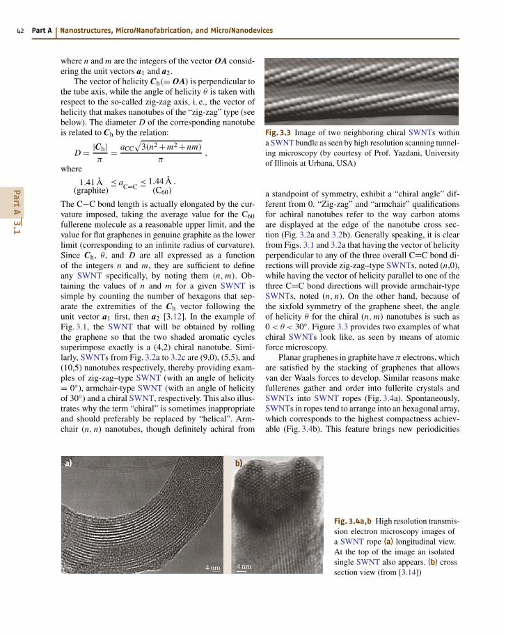
Fig. 3.4a,b High resolution transmis-sion electron microscopy images ofa SWNT rope (a) longitudinal view.At the top of the image an isolatedsingle SWNT also appears. (b) crosssection view (from [3.14])
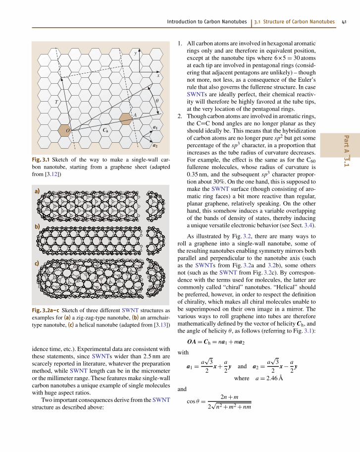
Fig. 3.3 Image of two neighboring chiral SWNTs withina SWNT bundle as seen by high resolution scanning tunnel-ing microscopy (by courtesy of Prof. Yazdani, Universityof Illinois at Urbana, USA)
a standpoint of symmetry, exhibit a “chiral angle” dif-ferent from 0. “Zig-zag” and “armchair” qualificationsfor achiral nanotubes refer to the way carbon atomsare displayed at the edge of the nanotube cross sec-tion (Fig. 3.2a and 3.2b). Generally speaking, it is clearfrom Figs. 3.1 and 3.2a that having the vector of helicityperpendicular to any of the three overall C=C bond di-rections will provide zig-zag–type SWNTs, noted (n,0),while having the vector of helicity parallel to one of thethree C=C bond directions will provide armchair-typeSWNTs, noted (n, n). On the other hand, because ofthe sixfold symmetry of the graphene sheet, the angleof helicity θ for the chiral (n, m) nanotubes is such as0 < θ < 30. Figure 3.3 provides two examples of whatchiral SWNTs look like, as seen by means of atomicforce microscopy.
Planar graphenes in graphite have π electrons, whichare satisfied by the stacking of graphenes that allowsvan der Waals forces to develop. Similar reasons makefullerenes gather and order into fullerite crystals andSWNTs into SWNT ropes (Fig. 3.4a). Spontaneously,SWNTs in ropes tend to arrange into an hexagonal array,which corresponds to the highest compactness achiev-able (Fig. 3.4b). This feature brings new periodicities
PartA
3.1
Introduction to Carbon Nanotubes 3.1 Structure of Carbon Nanotubes 43
with respect to graphite or turbostratic polyaromaticcarbon crystals. Turbostatic structure corresponds tographenes which are stacked with random rotationsor translations instead of being piled up following se-quential ABAB positions, as in graphite structure. Thisimplies that no lattice atom plane exists anymore otherthan the graphene planes themselves (correspondingto the (001) atom plane family). These new peri-odicities make diffraction patterns specific and quitedifferent from that of other sp2-carbon-based crystals,although hk reflections, which account for the hexa-gonal symmetry of graphene plane, are still present.On the other hand, 00l reflections, which account forthe stacking sequence of graphenes in regular, “mul-tilayered” polyaromatic crystals that does not exist inSWNT ropes, are absent. Such a hexagonal packingof SWNTs within the ropes requires that SWNTs ex-hibit similar diameters, which is the common casefor SWNTs prepared by the electric arc or the laservaporization processes. SWNTs prepared these waysare actually about 1.35 nm wide (diameter value fora (10,10) tube, among others), for reasons still un-clear but related to the growth mechanisms specificto the conditions provided by these techniques (seeSect. 3.3).
3.1.2 Multiwall Nanotubes
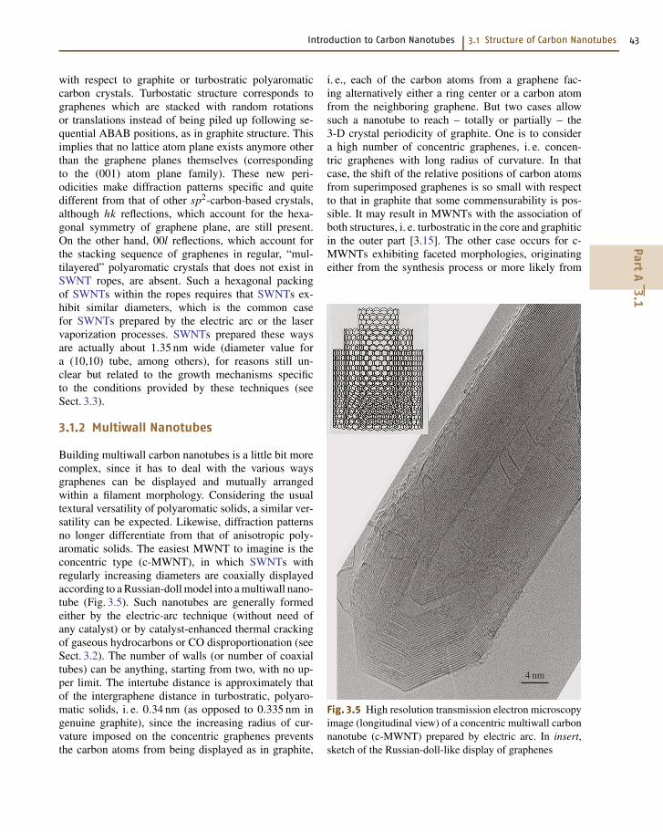
Building multiwall carbon nanotubes is a little bit morecomplex, since it has to deal with the various waysgraphenes can be displayed and mutually arrangedwithin a filament morphology. Considering the usualtextural versatility of polyaromatic solids, a similar ver-satility can be expected. Likewise, diffraction patternsno longer differentiate from that of anisotropic poly-aromatic solids. The easiest MWNT to imagine is theconcentric type (c-MWNT), in which SWNTs withregularly increasing diameters are coaxially displayedaccording to a Russian-doll model into a multiwall nano-tube (Fig. 3.5). Such nanotubes are generally formedeither by the electric-arc technique (without need ofany catalyst) or by catalyst-enhanced thermal crackingof gaseous hydrocarbons or CO disproportionation (seeSect. 3.2). The number of walls (or number of coaxialtubes) can be anything, starting from two, with no up-per limit. The intertube distance is approximately thatof the intergraphene distance in turbostratic, polyaro-matic solids, i. e. 0.34 nm (as opposed to 0.335 nm ingenuine graphite), since the increasing radius of cur-vature imposed on the concentric graphenes preventsthe carbon atoms from being displayed as in graphite,
i. e., each of the carbon atoms from a graphene fac-ing alternatively either a ring center or a carbon atomfrom the neighboring graphene. But two cases allowsuch a nanotube to reach – totally or partially – the3-D crystal periodicity of graphite. One is to considera high number of concentric graphenes, i. e. concen-tric graphenes with long radius of curvature. In thatcase, the shift of the relative positions of carbon atomsfrom superimposed graphenes is so small with respectto that in graphite that some commensurability is pos-sible. It may result in MWNTs with the association ofboth structures, i. e. turbostratic in the core and graphiticin the outer part [3.15]. The other case occurs for c-MWNTs exhibiting faceted morphologies, originatingeither from the synthesis process or more likely from
4 nm
Fig. 3.5 High resolution transmission electron microscopyimage (longitudinal view) of a concentric multiwall carbonnanotube (c-MWNT) prepared by electric arc. In insert,sketch of the Russian-doll-like display of graphenes
PartA
3.1
44 Part A Nanostructures, Micro/Nanofabrication, and Micro/Nanodevices
subsequent heat-treatments at high temperatures (e.g.,2,500 C) in inert atmospheres. Obviously, facets allowgraphenes to get back a flat arrangement of atoms –except at the junction between neighboring facets – inwhich the specific stacking sequence of graphite candevelop.
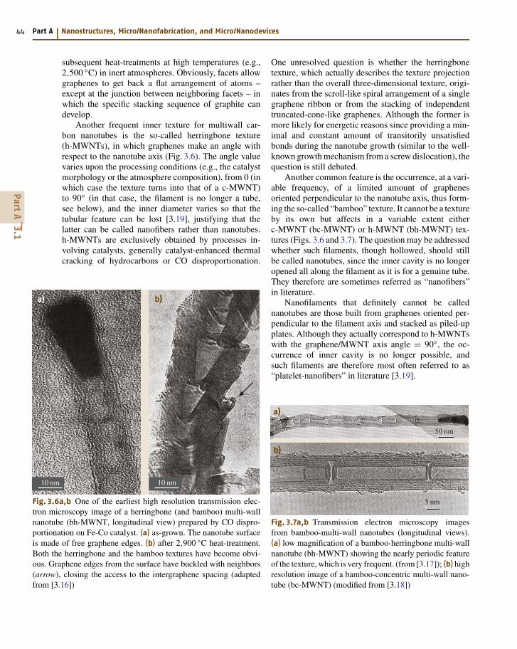
Another frequent inner texture for multiwall car-bon nanotubes is the so-called herringbone texture(h-MWNTs), in which graphenes make an angle withrespect to the nanotube axis (Fig. 3.6). The angle valuevaries upon the processing conditions (e.g., the catalystmorphology or the atmosphere composition), from 0 (inwhich case the texture turns into that of a c-MWNT)to 90 (in that case, the filament is no longer a tube,see below), and the inner diameter varies so that thetubular feature can be lost [3.19], justifying that thelatter can be called nanofibers rather than nanotubes.h-MWNTs are exclusively obtained by processes in-volving catalysts, generally catalyst-enhanced thermalcracking of hydrocarbons or CO disproportionation.
a) b)
10 nm10 nm
Fig. 3.6a,b One of the earliest high resolution transmission elec-tron microscopy image of a herringbone (and bamboo) multi-wallnanotube (bh-MWNT, longitudinal view) prepared by CO dispro-portionation on Fe-Co catalyst. (a) as-grown. The nanotube surfaceis made of free graphene edges. (b) after 2,900 C heat-treatment.Both the herringbone and the bamboo textures have become obvi-ous. Graphene edges from the surface have buckled with neighbors(arrow), closing the access to the intergraphene spacing (adaptedfrom [3.16])
One unresolved question is whether the herringbonetexture, which actually describes the texture projectionrather than the overall three-dimensional texture, origi-nates from the scroll-like spiral arrangement of a singlegraphene ribbon or from the stacking of independenttruncated-cone-like graphenes. Although the former ismore likely for energetic reasons since providing a min-imal and constant amount of transitorily unsatisfiedbonds during the nanotube growth (similar to the well-known growth mechanism from a screw dislocation), thequestion is still debated.
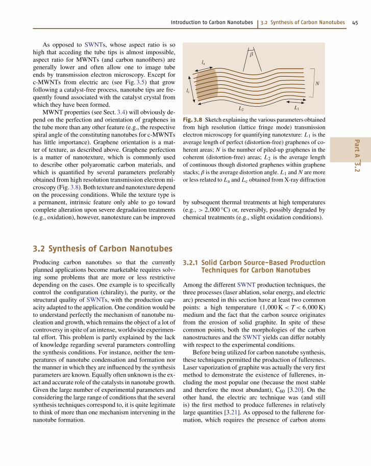
Another common feature is the occurrence, at a vari-able frequency, of a limited amount of graphenesoriented perpendicular to the nanotube axis, thus form-ing the so-called “bamboo” texture. It cannot be a textureby its own but affects in a variable extent eitherc-MWNT (bc-MWNT) or h-MWNT (bh-MWNT) tex-tures (Figs. 3.6 and 3.7). The question may be addressedwhether such filaments, though hollowed, should stillbe called nanotubes, since the inner cavity is no longeropened all along the filament as it is for a genuine tube.They therefore are sometimes referred as “nanofibers”in literature.
Nanofilaments that definitely cannot be callednanotubes are those built from graphenes oriented per-pendicular to the filament axis and stacked as piled-upplates. Although they actually correspond to h-MWNTswith the graphene/MWNT axis angle = 90, the oc-currence of inner cavity is no longer possible, andsuch filaments are therefore most often referred to as“platelet-nanofibers” in literature [3.19].
a)
b)
5 nm
50 nm
Fig. 3.7a,b Transmission electron microscopy imagesfrom bamboo-multi-wall nanotubes (longitudinal views).(a) low magnification of a bamboo-herringbone multi-wallnanotube (bh-MWNT) showing the nearly periodic featureof the texture, which is very frequent. (from [3.17]); (b) highresolution image of a bamboo-concentric multi-wall nano-tube (bc-MWNT) (modified from [3.18])
PartA
3.1
Introduction to Carbon Nanotubes 3.2 Synthesis of Carbon Nanotubes 45
As opposed to SWNTs, whose aspect ratio is sohigh that acceding the tube tips is almost impossible,aspect ratio for MWNTs (and carbon nanofibers) aregenerally lower and often allow one to image tubeends by transmission electron microscopy. Except forc-MWNTs from electric arc (see Fig. 3.5) that growfollowing a catalyst-free process, nanotube tips are fre-quently found associated with the catalyst crystal fromwhich they have been formed.
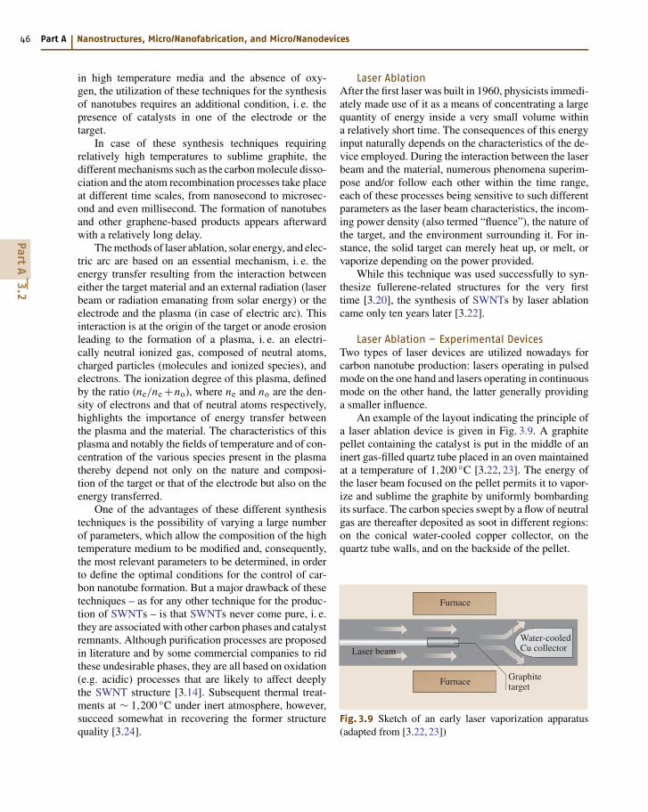
MWNT properties (see Sect. 3.4) will obviously de-pend on the perfection and orientation of graphenes inthe tube more than any other feature (e.g., the respectivespiral angle of the constituting nanotubes for c-MWNTshas little importance). Graphene orientation is a mat-ter of texture, as described above. Graphene perfectionis a matter of nanotexture, which is commonly usedto describe other polyaromatic carbon materials, andwhich is quantified by several parameters preferablyobtained from high resolution transmission electron mi-croscopy (Fig. 3.8). Both texture and nanotexture dependon the processing conditions. While the texture type isa permanent, intrinsic feature only able to go towardcomplete alteration upon severe degradation treatments(e.g., oxidation), however, nanotexture can be improved
la
lc
L2 L1
N
Fig. 3.8 Sketch explaining the various parameters obtainedfrom high resolution (lattice fringe mode) transmissionelectron microscopy for quantifying nanotexture: L1 is theaverage length of perfect (distortion-free) graphenes of co-herent areas; N is the number of piled-up graphenes in thecoherent (distortion-free) areas; L2 is the average lengthof continuous though distorted graphenes within graphenestacks; β is the average distortion angle. L1 and N are moreor less related to La and Lc obtained from X-ray diffraction
by subsequent thermal treatments at high temperatures(e.g., > 2,000 C) or, reversibly, possibly degraded bychemical treatments (e.g., slight oxidation conditions).
3.2 Synthesis of Carbon Nanotubes
Producing carbon nanotubes so that the currentlyplanned applications become marketable requires solv-ing some problems that are more or less restrictivedepending on the cases. One example is to specificallycontrol the configuration (chirality), the purity, or thestructural quality of SWNTs, with the production cap-acity adapted to the application. One condition would beto understand perfectly the mechanism of nanotube nu-cleation and growth, which remains the object of a lot ofcontroversy in spite of an intense, worldwide experimen-tal effort. This problem is partly explained by the lackof knowledge regarding several parameters controllingthe synthesis conditions. For instance, neither the tem-peratures of nanotube condensation and formation northe manner in which they are influenced by the synthesisparameters are known. Equally often unknown is the ex-act and accurate role of the catalysts in nanotube growth.Given the large number of experimental parameters andconsidering the large range of conditions that the severalsynthesis techniques correspond to, it is quite legitimateto think of more than one mechanism intervening in thenanotube formation.
3.2.1 Solid Carbon Source-Based ProductionTechniques for Carbon Nanotubes
Among the different SWNT production techniques, thethree processes (laser ablation, solar energy, and electricarc) presented in this section have at least two commonpoints: a high temperature (1,000 K < T < 6,000 K)medium and the fact that the carbon source originatesfrom the erosion of solid graphite. In spite of thesecommon points, both the morphologies of the carbonnanostructures and the SWNT yields can differ notablywith respect to the experimental conditions.
Before being utilized for carbon nanotube synthesis,these techniques permitted the production of fullerenes.Laser vaporization of graphite was actually the very firstmethod to demonstrate the existence of fullerenes, in-cluding the most popular one (because the most stableand therefore the most abundant), C60 [3.20]. On theother hand, the electric arc technique was (and stillis) the first method to produce fullerenes in relativelylarge quantities [3.21]. As opposed to the fullerene for-mation, which requires the presence of carbon atoms
PartA
3.2
46 Part A Nanostructures, Micro/Nanofabrication, and Micro/Nanodevices
in high temperature media and the absence of oxy-gen, the utilization of these techniques for the synthesisof nanotubes requires an additional condition, i. e. thepresence of catalysts in one of the electrode or thetarget.
In case of these synthesis techniques requiringrelatively high temperatures to sublime graphite, thedifferent mechanisms such as the carbon molecule disso-ciation and the atom recombination processes take placeat different time scales, from nanosecond to microsec-ond and even millisecond. The formation of nanotubesand other graphene-based products appears afterwardwith a relatively long delay.
The methods of laser ablation, solar energy, and elec-tric arc are based on an essential mechanism, i. e. theenergy transfer resulting from the interaction betweeneither the target material and an external radiation (laserbeam or radiation emanating from solar energy) or theelectrode and the plasma (in case of electric arc). Thisinteraction is at the origin of the target or anode erosionleading to the formation of a plasma, i. e. an electri-cally neutral ionized gas, composed of neutral atoms,charged particles (molecules and ionized species), andelectrons. The ionization degree of this plasma, definedby the ratio (ne/ne +no), where ne and no are the den-sity of electrons and that of neutral atoms respectively,highlights the importance of energy transfer betweenthe plasma and the material. The characteristics of thisplasma and notably the fields of temperature and of con-centration of the various species present in the plasmathereby depend not only on the nature and composi-tion of the target or that of the electrode but also on theenergy transferred.
One of the advantages of these different synthesistechniques is the possibility of varying a large numberof parameters, which allow the composition of the hightemperature medium to be modified and, consequently,the most relevant parameters to be determined, in orderto define the optimal conditions for the control of car-bon nanotube formation. But a major drawback of thesetechniques – as for any other technique for the produc-tion of SWNTs – is that SWNTs never come pure, i. e.they are associated with other carbon phases and catalystremnants. Although purification processes are proposedin literature and by some commercial companies to ridthese undesirable phases, they are all based on oxidation(e.g. acidic) processes that are likely to affect deeplythe SWNT structure [3.14]. Subsequent thermal treat-ments at ∼ 1,200 C under inert atmosphere, however,succeed somewhat in recovering the former structurequality [3.24].
Laser AblationAfter the first laser was built in 1960, physicists immedi-ately made use of it as a means of concentrating a largequantity of energy inside a very small volume withina relatively short time. The consequences of this energyinput naturally depends on the characteristics of the de-vice employed. During the interaction between the laserbeam and the material, numerous phenomena superim-pose and/or follow each other within the time range,each of these processes being sensitive to such differentparameters as the laser beam characteristics, the incom-ing power density (also termed “fluence”), the nature ofthe target, and the environment surrounding it. For in-stance, the solid target can merely heat up, or melt, orvaporize depending on the power provided.
While this technique was used successfully to syn-thesize fullerene-related structures for the very firsttime [3.20], the synthesis of SWNTs by laser ablationcame only ten years later [3.22].
Laser Ablation – Experimental DevicesTwo types of laser devices are utilized nowadays forcarbon nanotube production: lasers operating in pulsedmode on the one hand and lasers operating in continuousmode on the other hand, the latter generally providinga smaller influence.
An example of the layout indicating the principle ofa laser ablation device is given in Fig. 3.9. A graphitepellet containing the catalyst is put in the middle of aninert gas-filled quartz tube placed in an oven maintainedat a temperature of 1,200 C [3.22, 23]. The energy ofthe laser beam focused on the pellet permits it to vapor-ize and sublime the graphite by uniformly bombardingits surface. The carbon species swept by a flow of neutralgas are thereafter deposited as soot in different regions:on the conical water-cooled copper collector, on thequartz tube walls, and on the backside of the pellet.
Laser beam
Graphitetarget
Water-cooledCu collector
Furnace
Furnace
Fig. 3.9 Sketch of an early laser vaporization apparatus(adapted from [3.22, 23])
PartA
3.2
Introduction to Carbon Nanotubes 3.2 Synthesis of Carbon Nanotubes 47
Various improvements have been made to this de-vice in order to increase the production efficiency. Forexample, Thess et al. [3.25] employed a second pulsedlaser that follows the initial impulsion but at a differ-ent frequency in order to ensure a more complete andefficient irradiation of the pellet. This second impul-sion has the role of vaporizing the coarse aggregatesissued from the first ablation and thereby making themparticipate in the active carbon feedstock involved inthe nanotube growth. Other modifications were broughtby Rinzler et al. [3.24], who inserted a second quartztube of a smaller diameter coaxially disposed insideto the first one. This second tube has the role of re-ducing the vaporization zone and thereby permitting anincrease in the quantity of sublimed carbon. They alsoarranged to place the graphite pellet on a revolving sys-tem so that the laser beam uniformly scans its wholesurface.
Other groups have realized that, as far as the tar-get contains both the catalyst and the graphite, the latterevaporates in priority and the pellet surface becomesmore and more metal rich, resulting in a decrease ofthe efficiency in nanotube formation in the course of theprocess. To solve this problem, Yudasaka et al. [3.27]utilized two pellets facing each other, one entirelymade from the graphite powder and the other froman alloy of transition metals (catalysts), and irradiatedsimultaneously.
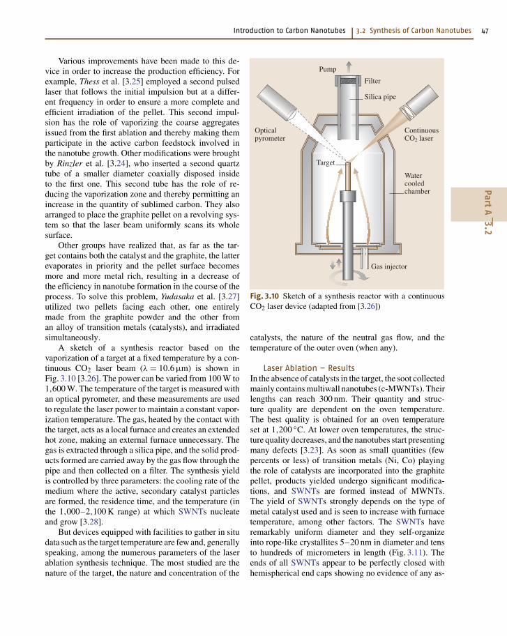
A sketch of a synthesis reactor based on thevaporization of a target at a fixed temperature by a con-tinuous CO2 laser beam (λ = 10.6 µm) is shown inFig. 3.10 [3.26]. The power can be varied from 100 W to1,600 W. The temperature of the target is measured withan optical pyrometer, and these measurements are usedto regulate the laser power to maintain a constant vapor-ization temperature. The gas, heated by the contact withthe target, acts as a local furnace and creates an extendedhot zone, making an external furnace unnecessary. Thegas is extracted through a silica pipe, and the solid prod-ucts formed are carried away by the gas flow through thepipe and then collected on a filter. The synthesis yieldis controlled by three parameters: the cooling rate of themedium where the active, secondary catalyst particlesare formed, the residence time, and the temperature (inthe 1,000–2,100 K range) at which SWNTs nucleateand grow [3.28].
But devices equipped with facilities to gather in situdata such as the target temperature are few and, generallyspeaking, among the numerous parameters of the laserablation synthesis technique. The most studied are thenature of the target, the nature and concentration of the
Pump
Filter
Silica pipe
ContinuousCO2 laser
Opticalpyrometer
Target
Watercooledchamber
Gas injector
Fig. 3.10 Sketch of a synthesis reactor with a continuousCO2 laser device (adapted from [3.26])
catalysts, the nature of the neutral gas flow, and thetemperature of the outer oven (when any).
Laser Ablation – ResultsIn the absence of catalysts in the target, the soot collectedmainly contains multiwall nanotubes (c-MWNTs). Theirlengths can reach 300 nm. Their quantity and struc-ture quality are dependent on the oven temperature.The best quality is obtained for an oven temperatureset at 1,200 C. At lower oven temperatures, the struc-ture quality decreases, and the nanotubes start presentingmany defects [3.23]. As soon as small quantities (fewpercents or less) of transition metals (Ni, Co) playingthe role of catalysts are incorporated into the graphitepellet, products yielded undergo significant modifica-tions, and SWNTs are formed instead of MWNTs.The yield of SWNTs strongly depends on the type ofmetal catalyst used and is seen to increase with furnacetemperature, among other factors. The SWNTs haveremarkably uniform diameter and they self-organizeinto rope-like crystallites 5–20 nm in diameter and tensto hundreds of micrometers in length (Fig. 3.11). Theends of all SWNTs appear to be perfectly closed withhemispherical end caps showing no evidence of any as-
PartA
3.2
48 Part A Nanostructures, Micro/Nanofabrication, and Micro/Nanodevices
200 nm
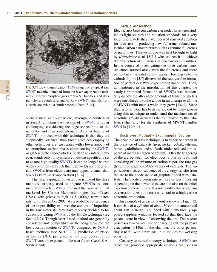
Fig. 3.11 Low magnification TEM images of a typical rawSWNT material obtained from the laser vaporization tech-nique. Fibrous morphologies are SWNT bundles, and darkparticles are catalyst remnants. Raw SWNT materials fromelectric arc exhibit a similar aspect (from [3.14])
sociated metal catalyst particle, although, as pointed outin Sect. 3.1, finding the two tips of a SWNT is ratherchallenging, considering the huge aspect ratio of thenanotube and their entanglement. Another feature ofSWNTs produced with this technique is that they aresupposedly “cleaner” than those produced employingother techniques, i. e., associated with a lower amount ofan amorphous carbon phase, either coating the SWNTsor gathered into nano-particles. Such an advantage, how-ever, stands only for synthesis conditions specifically setto ensure high quality SWNTs. It can no longer be truewhen conditions are such that high yields are preferred,and SWNTs from electric arc may appear cleaner thanSWNTs from laser vaporization [3.14].
The laser vaporization technique is one of the threemethods currently used to prepare SWNTs as com-mercial products. SWNTs prepared that way were firstmarketed by Carbon Nanotechnologies Inc. (Texas,USA), with prices as high as $ 1,000/g (raw mater-ials) until December 2002. As a probable consequenceof the impossibility to lower the amount of impuritiesin the raw materials, they have recently decided to fo-cus on fabricating SWNTs by the HiPCo technique (seeSect. 3.2.2). Though laser-based method are generallyconsidered not competitive in the long term for thelow-cost production of SWNTs compared to CCVD-based methods (see Sect. 3.2.2), prediction of pricesas low as $ 0.03 per gram of raw high concentrationSWNT soot are expected in the near future (Acolt S.A.,Switzerland).
Electric-Arc MethodElectric arcs between carbon electrodes have been stud-ied as light sources and radiation standards for a verylong time. Lately they have received renewed attentionfor their use in producing new fullerenes-related mo-lecular carbon nanostructures such as genuine fullerenesor nanotubes. This technique was first brought to lightby Krätschmer et al. [3.21] who utilized it to achievethe production of fullerenes in macroscopic quantities.In the course of investigating the other carbon nano-structures formed along with the fullerenes and moreparticularly the solid carbon deposit forming onto thecathode, Iijima [3.7] discovered the catalyst-free forma-tion of perfect c-MWNT-type carbon nanotubes. Then,as mentioned in the introduction of this chapter, thecatalyst-promoted formation of SWNTs was inciden-tally discovered after some amounts of transition metalswere introduced into the anode in an attempt to fill thec-MWNTs with metals while they grow [3.8, 9]. Sincethen, a lot of work has been carried out by many groupsusing this technique to understand the mechanisms ofnanotube growth as well as the role played by the cata-lysts (when any) for the synthesis of MWNTs and/orSWNTs [3.29–41].
Electric-Art Method – Experimental DevicesThe principle of this technique is to vaporize carbon inthe presence of catalysts (iron, nickel, cobalt, yttrium,boron, gadolinium, and so forth) under reduced atmos-phere of inert gas (argon or helium). After the triggeringof the arc between two electrodes, a plasma is formedconsisting of the mixture of carbon vapor, the rare gas(helium or argon), and the vapors of catalysts. The va-porization is the consequence of the energy transfer fromthe arc to the anode made of graphite doped with cata-lysts. The anode erosion rate is more or less importantdepending on the power of the arc and also on the otherexperimental conditions. It is noteworthy that a high an-ode erosion does not necessarily lead to a high carbonnanotube production.
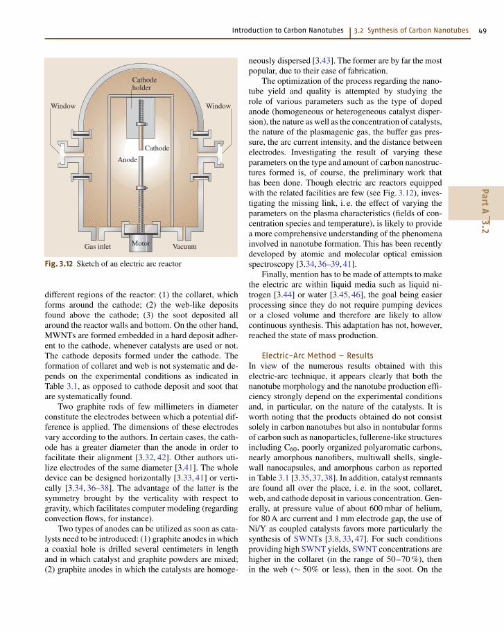
An example of a reactor layout is shown in Fig. 3.12.It consists of a cylinder of about 30 cm in diameter andabout 1 m in height, equipped with diametrically op-posed sapphire windows located so that they face theplasma zone in view of observing the arc. The reactorpossesses two valves, one for carrying out the primaryevacuation (0.1 Pa) of the chamber, the other permit-ting it to fill with a rare gas up to the desired workingpressure.
Contrary to the solar energy technique, SWNTs aredeposited (provided appropriate catalysts are used) in
PartA
3.2
Introduction to Carbon Nanotubes 3.2 Synthesis of Carbon Nanotubes 49
Cathodeholder
Cathode
Anode
WindowWindow
Motor VacuumGas inlet
Fig. 3.12 Sketch of an electric arc reactor
different regions of the reactor: (1) the collaret, whichforms around the cathode; (2) the web-like depositsfound above the cathode; (3) the soot deposited allaround the reactor walls and bottom. On the other hand,MWNTs are formed embedded in a hard deposit adher-ent to the cathode, whenever catalysts are used or not.The cathode deposits formed under the cathode. Theformation of collaret and web is not systematic and de-pends on the experimental conditions as indicated inTable 3.1, as opposed to cathode deposit and soot thatare systematically found.
Two graphite rods of few millimeters in diameterconstitute the electrodes between which a potential dif-ference is applied. The dimensions of these electrodesvary according to the authors. In certain cases, the cath-ode has a greater diameter than the anode in order tofacilitate their alignment [3.32, 42]. Other authors uti-lize electrodes of the same diameter [3.41]. The wholedevice can be designed horizontally [3.33, 41] or verti-cally [3.34, 36–38]. The advantage of the latter is thesymmetry brought by the verticality with respect togravity, which facilitates computer modeling (regardingconvection flows, for instance).
Two types of anodes can be utilized as soon as cata-lysts need to be introduced: (1) graphite anodes in whicha coaxial hole is drilled several centimeters in lengthand in which catalyst and graphite powders are mixed;(2) graphite anodes in which the catalysts are homoge-
neously dispersed [3.43]. The former are by far the mostpopular, due to their ease of fabrication.
The optimization of the process regarding the nano-tube yield and quality is attempted by studying therole of various parameters such as the type of dopedanode (homogeneous or heterogeneous catalyst disper-sion), the nature as well as the concentration of catalysts,the nature of the plasmagenic gas, the buffer gas pres-sure, the arc current intensity, and the distance betweenelectrodes. Investigating the result of varying theseparameters on the type and amount of carbon nanostruc-tures formed is, of course, the preliminary work thathas been done. Though electric arc reactors equippedwith the related facilities are few (see Fig. 3.12), inves-tigating the missing link, i. e. the effect of varying theparameters on the plasma characteristics (fields of con-centration species and temperature), is likely to providea more comprehensive understanding of the phenomenainvolved in nanotube formation. This has been recentlydeveloped by atomic and molecular optical emissionspectroscopy [3.34, 36–39, 41].
Finally, mention has to be made of attempts to makethe electric arc within liquid media such as liquid ni-trogen [3.44] or water [3.45, 46], the goal being easierprocessing since they do not require pumping devicesor a closed volume and therefore are likely to allowcontinuous synthesis. This adaptation has not, however,reached the state of mass production.
Electric-Arc Method – ResultsIn view of the numerous results obtained with thiselectric-arc technique, it appears clearly that both thenanotube morphology and the nanotube production effi-ciency strongly depend on the experimental conditionsand, in particular, on the nature of the catalysts. It isworth noting that the products obtained do not consistsolely in carbon nanotubes but also in nontubular formsof carbon such as nanoparticles, fullerene-like structuresincluding C60, poorly organized polyaromatic carbons,nearly amorphous nanofibers, multiwall shells, single-wall nanocapsules, and amorphous carbon as reportedin Table 3.1 [3.35,37,38]. In addition, catalyst remnantsare found all over the place, i. e. in the soot, collaret,web, and cathode deposit in various concentration. Gen-erally, at pressure value of about 600 mbar of helium,for 80 A arc current and 1 mm electrode gap, the use ofNi/Y as coupled catalysts favors more particularly thesynthesis of SWNTs [3.8, 33, 47]. For such conditionsproviding high SWNT yields, SWNT concentrations arehigher in the collaret (in the range of 50–70 %), thenin the web (∼ 50% or less), then in the soot. On the
PartA
3.2
50 Part A Nanostructures, Micro/Nanofabrication, and Micro/Nanodevices
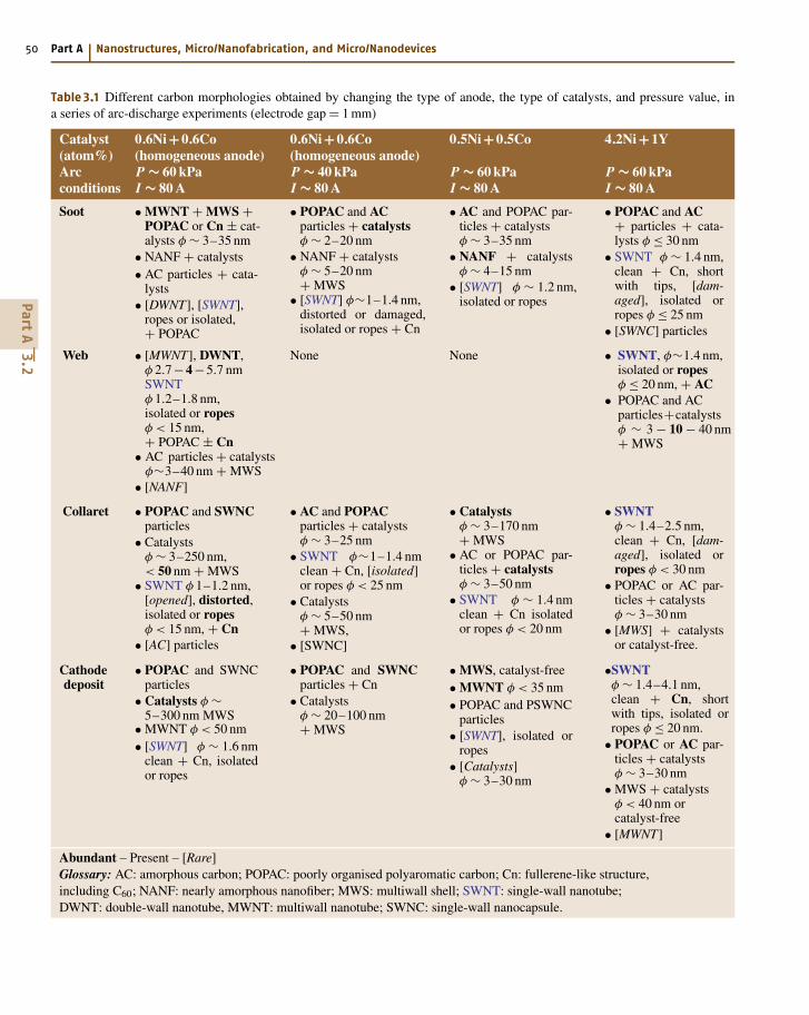
Table 3.1 Different carbon morphologies obtained by changing the type of anode, the type of catalysts, and pressure value, ina series of arc-discharge experiments (electrode gap = 1 mm)
Catalyst 0.6Ni+0.6Co 0.6Ni+0.6Co 0.5Ni+0.5Co 4.2Ni+1Y(atom%) (homogeneous anode) (homogeneous anode)Arc P ∼ 60 kPa P ∼ 40 kPa P ∼ 60 kPa P ∼ 60 kPaconditions I ∼ 80 A I ∼ 80 A I ∼ 80 A I ∼ 80 A
Soot • MWNT + MWS +POPAC or Cn ± cat-alysts φ ∼ 3–35 nm
• NANF + catalysts• AC particles + cata-
lysts• [DWNT], [SWNT],
ropes or isolated,+ POPAC
• POPAC and ACparticles + catalystsφ ∼ 2–20 nm
• NANF + catalystsφ ∼ 5–20 nm+ MWS
• [SWNT] φ∼1–1.4 nm,distorted or damaged,isolated or ropes + Cn
• AC and POPAC par-ticles + catalystsφ ∼ 3–35 nm
• NANF + catalystsφ ∼ 4–15 nm
• [SWNT] φ ∼ 1.2 nm,isolated or ropes
• POPAC and AC+ particles + cata-lysts φ ≤ 30 nm
• SWNT φ ∼ 1.4 nm,clean + Cn, shortwith tips, [dam-aged], isolated orropes φ ≤ 25 nm
• [SWNC] particles
Web • [MWNT], DWNT,φ 2.7−4−5.7 nmSWNTφ 1.2–1.8 nm,isolated or ropesφ < 15 nm,+ POPAC ± Cn
• AC particles + catalystsφ∼3–40 nm + MWS
• [NANF]
None None • SWNT, φ∼1.4 nm,isolated or ropesφ ≤ 20 nm, + AC
• POPAC and ACparticles+catalystsφ ∼ 3 − 10 − 40 nm+ MWS
Collaret • POPAC and SWNCparticles
• Catalystsφ ∼ 3–250 nm,< 50 nm + MWS
• SWNT φ 1–1.2 nm,[opened], distorted,isolated or ropesφ < 15 nm, + Cn
• [AC] particles
• AC and POPACparticles + catalystsφ ∼ 3–25 nm
• SWNT φ∼1–1.4 nmclean + Cn, [isolated]or ropes φ < 25 nm
• Catalystsφ ∼ 5–50 nm+ MWS,
• [SWNC]
• Catalystsφ ∼ 3–170 nm+ MWS
• AC or POPAC par-ticles + catalystsφ ∼ 3–50 nm
• SWNT φ ∼ 1.4 nmclean + Cn isolatedor ropes φ < 20 nm
• SWNTφ ∼ 1.4–2.5 nm,clean + Cn, [dam-aged], isolated orropes φ < 30 nm
• POPAC or AC par-ticles + catalystsφ ∼ 3–30 nm
• [MWS] + catalystsor catalyst-free.
Cathodedeposit
• POPAC and SWNCparticles
• Catalysts φ ∼5–300 nm MWS
• MWNT φ < 50 nm• [SWNT] φ ∼ 1.6 nm
clean + Cn, isolatedor ropes
• POPAC and SWNCparticles + Cn
• Catalystsφ ∼ 20–100 nm+ MWS
• MWS, catalyst-free• MWNT φ < 35 nm• POPAC and PSWNC
particles• [SWNT], isolated or
ropes• [Catalysts]
φ ∼ 3–30 nm
•SWNTφ ∼ 1.4–4.1 nm,clean + Cn, shortwith tips, isolated orropes φ ≤ 20 nm.
• POPAC or AC par-ticles + catalystsφ ∼ 3–30 nm
• MWS + catalystsφ < 40 nm orcatalyst-free
• [MWNT]
Abundant – Present – [Rare]Glossary: AC: amorphous carbon; POPAC: poorly organised polyaromatic carbon; Cn: fullerene-like structure,including C60; NANF: nearly amorphous nanofiber; MWS: multiwall shell; SWNT: single-wall nanotube;DWNT: double-wall nanotube, MWNT: multiwall nanotube; SWNC: single-wall nanocapsule.
PartA
3.2
Introduction to Carbon Nanotubes 3.2 Synthesis of Carbon Nanotubes 51
other hand, c-MWNTs are found in the cathode deposit.SWNT lengths are micrometric and, typically, outerdiameters range around 1.4 nm. Taking the latter con-ditions as a reference experiment (Table 3.1, column 4),Table 3.1 illustrates the consequence of changing theparameters. For instance (Table 3.1, column 3), usingNi/Co instead of Ni/Y as catalysts prevents the formationof SWNTs. But when the Ni/Co catalysts are homoge-neously dispersed in the anode (Table 3.1, column 1), theformation of nanotubes is promoted again, but MWNTswith two or three walls prevail over SWNTs, amongwhich DWNTs (double-wall nanotubes) make a major-ity. But it is enough to decrease the ambient pressurefrom 60 to 40 kPa (Table 3.1, column 2) for gettingback to conditions where the nanotube formation isimpeached.
Recent works have attempted to replace graphitepowder (sp2 hybridized carbon) by diamond powder(sp3 hybridized carbon) to mix with the catalyst pow-der and fill hollowed-type graphite anodes. The resultwas an unexpected but quite significant increase (up to+230%) in the SWNT yield [3.39,40]. Such experimentsreveal, as for the comparison between the results fromusing homogeneous instead of heterogeneous anodesthat the physical phenomena (charge and heat transfers)that occurred in the anode during the arc are of utmostimportance, which was neglected until now.
It is clear that while the use of rare earth element(such as Y) as a single catalyst does not provide theconditions to grow SWNTs, associating it with a tran-sition metal (such as Ni/Y) seems to correspond to themost appropriate combinations, leading to the highestSWNT yields [3.42]. On the other hand, using a singlerare earth element may lead to unexpected results, suchas the anticipated closure of graphene edges from a c-MWNT wall with the neighboring graphene edges fromthe same wall side, leading to the preferred formationof telescope-like and open c-MWNTs able to containnested Gd crystals [3.36,38]. Such a need for bimetalliccatalysts has just begun to be understood as a possi-ble requirement to promote the transitory formation ofnickel particles coated with yttrium carbide, whose lat-tice constants are somewhat commensurable with thatof graphenes [3.48].
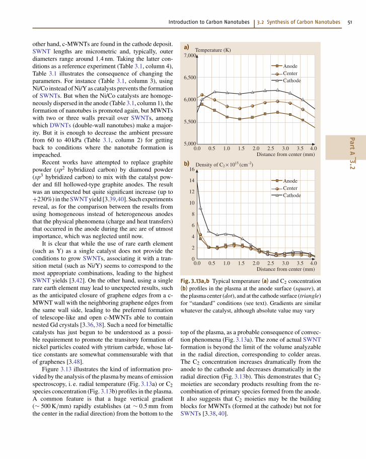
Figure 3.13 illustrates the kind of information pro-vided by the analysis of the plasma by means of emissionspectroscopy, i. e. radial temperature (Fig. 3.13a) or C2species concentration (Fig. 3.13b) profiles in the plasma.A common feature is that a huge vertical gradient(∼ 500 K/mm) rapidly establishes (at ∼ 0.5 mm fromthe center in the radial direction) from the bottom to the
7,000
6,500
6,000
5,500
5,0000.0 0.5 1.0 1.5 2.0 2.5 3.0 3.5 4.0
Temperature (K)
Distance from center (mm)
AnodeCenterCathode
a)
16
14
12
10
8
6
4
2
00.0 0.5 1.0 1.5 2.0 2.5 3.0 3.5 4.0
Density of C2 × 1015 (cm–2)
Distance from center (mm)
AnodeCenterCathode
b)
Fig. 3.13a,b Typical temperature (a) and C2 concentration(b) profiles in the plasma at the anode surface (square), atthe plasma center (dot), and at the cathode surface (triangle)for “standard” conditions (see text). Gradients are similarwhatever the catalyst, although absolute value may vary
top of the plasma, as a probable consequence of convec-tion phenomena (Fig. 3.13a). The zone of actual SWNTformation is beyond the limit of the volume analyzablein the radial direction, corresponding to colder areas.The C2 concentration increases dramatically from theanode to the cathode and decreases dramatically in theradial direction (Fig. 3.13b). This demonstrates that C2moieties are secondary products resulting from the re-combination of primary species formed from the anode.It also suggests that C2 moieties may be the buildingblocks for MWNTs (formed at the cathode) but not forSWNTs [3.38, 40].
PartA
3.2
52 Part A Nanostructures, Micro/Nanofabrication, and Micro/Nanodevices
Although many aspects of it still need to be un-derstood, the electric-arc method is one of the threemethods currently used to produce SWNTs as com-mercial products. At the French company NanoledgeS.A. (Montpellier, France), for instance, current produc-tion (for 2003) reaches ∼ 20 kg/year (raw SWNTs, i. e.not purified), with a marketed price of ∼ 90 Euros/g,which is much cheaper than any other productionmethod so far. A decrease to 2–5 Euros/g is expected forsometime before 2007, with a SWNT production cap-acity of 4–5 tons/year. Amazingly, raw SWNTs fromelectric arc proposed by Bucky USA (Texas, USA) arestill proposed at a marketed price of $ 1,000/g.
Solar FurnaceSolar furnace devices were originally utilized byseveral groups to produce fullerenes [3.49–51].Heben et al. [3.52] and Laplaze et al. [3.53] later mod-ified their former devices in order to use them forcarbon nanotube production. This modification con-sisted mainly in using more powerful ovens [3.54, 55].
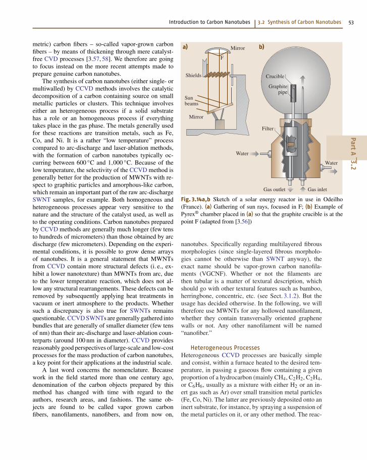
Solar Furnace – Experimental DevicesThe principle of this technique is again based on thesublimation in an inert gas of a mixture of graphitepowder and catalysts formerly placed in a crucible. Anexample of such a device is shown in Fig. 3.14. The so-lar rays are collected by a plain mirror and reflectedtoward a parabolic mirror that focuses them directlyonto a graphite pellet under controlled atmosphere. Thehigh temperature of about 4,000 K permits both thecarbon and the catalysts to vaporize. The vapors arethen dragged by the neutral gas and condense ontothe cold walls of the thermal screen. The reactor con-sists of a brass support cooled by water circulation, onwhich Pyrex® chambers with various shapes can be fixed(Fig. 3.14b). This support contains a watertight passagepermitting the introduction of the neutral gas and a cop-per rod on which the target is mounted. The target issurrounded by a graphite tube that plays both the role ofa thermal screen to reduce radiation losses (very impor-tant in the case of graphite) and the role of a duct to leadcarbon vapors to a filter in order to avoid soot deposits onthe Pyrex® chamber wall. A graphite crucible filled withpowdered graphite (for fullerene synthesis) or a mix-ture of graphite and catalysts (for nanotube synthesis) isutilized in order to reduce the conduction losses.
These studies primarily investigated the target com-position, the type and concentration of catalysts, theflow-rate, the composition and pressure of the plasma-genic gas inside the chamber, and the oven power. The
objectives are similar to that of works carried out withthe other solid-carbon-source-based processes. Whenpossible, specific in situ diagnostics (pyrometry, optic-al emission spectroscopy, etc.) are also performed inorder to understand better the role of the various param-eters (temperature measurements at the crucible surface,along the graphite tube acting as thermal screen, C2radical concentration in the immediate vicinity of thecrucible).
Solar Furnace – ResultsSome results obtained by different groups concerningthe influence of the catalysts can be summarized asfollows. With Ni/Co and at low pressure, the samplecollected contains mainly MWNTs with bamboo tex-ture, carbon shells, and some bundles of SWNTs [3.54].At higher pressures, only bundles of SWNTs are ob-tained with fewer carbon shells. With Ni/Y and at a highpressure, relatively long bundles of SWNTs are ob-served. With Co, SWNT bundles are obtained in thesoot with SWNT diameters ranging from 1 to 2 nm.Laplaze et al. [3.54] observed very few nanotubes buta large quantity of carbon shells.
In order to proceed to a large-scale synthesis ofsingle-wall carbon nanotubes, which is still a challengefor chemical engineers, Flamant et al. [3.56] recentlydemonstrated that solar energy–based synthesis is a ver-satile method to obtain SWNTs and can be scaled from0.1–0.5 g/h to 10 g/h and then to 100 g/h productivityusing existing solar furnaces. Experiments at mediumscale (10-g/h, 50 kW solar power) have proven the fea-sibility of designing and building such a reactor and ofthe scaling-up method. Numerical simulation was mean-while performed in order to improve the selectivity of thesynthesis, in particular by controlling the carbon vaporcooling rate.
3.2.2 Gaseous Carbon Source-BasedProduction Techniquesfor Carbon Nanotubes
As mentioned in the introduction of this chapter, thecatalysis-enhanced thermal cracking of gaseous car-bon source (hydrocarbons, CO) – commonly referredto as catalytic chemical vapor deposition (CCVD) –has been known to produce carbon nanofilaments fora long time [3.4], so that reporting all the works pub-lished in the field since the beginning of the centuryis almost impossible. Until the 90s, however, carbonnanofilaments were mainly produced to act as a coresubstrate for the subsequent growth of larger (micro-
PartA
3.2
Introduction to Carbon Nanotubes 3.2 Synthesis of Carbon Nanotubes 53
metric) carbon fibers – so-called vapor-grown carbonfibers – by means of thickening through mere catalyst-free CVD processes [3.57, 58]. We therefore are goingto focus instead on the more recent attempts made toprepare genuine carbon nanotubes.
The synthesis of carbon nanotubes (either single- ormultiwalled) by CCVD methods involves the catalyticdecomposition of a carbon containing source on smallmetallic particles or clusters. This technique involveseither an heterogeneous process if a solid substratehas a role or an homogeneous process if everythingtakes place in the gas phase. The metals generally usedfor these reactions are transition metals, such as Fe,Co, and Ni. It is a rather “low temperature” processcompared to arc-discharge and laser-ablation methods,with the formation of carbon nanotubes typically oc-curring between 600 C and 1,000 C. Because of thelow temperature, the selectivity of the CCVD method isgenerally better for the production of MWNTs with re-spect to graphitic particles and amorphous-like carbon,which remain an important part of the raw arc-dischargeSWNT samples, for example. Both homogeneous andheterogeneous processes appear very sensitive to thenature and the structure of the catalyst used, as well asto the operating conditions. Carbon nanotubes preparedby CCVD methods are generally much longer (few tensto hundreds of micrometers) than those obtained by arcdischarge (few micrometers). Depending on the experi-mental conditions, it is possible to grow dense arraysof nanotubes. It is a general statement that MWNTsfrom CCVD contain more structural defects (i. e., ex-hibit a lower nanotexture) than MWNTs from arc, dueto the lower temperature reaction, which does not al-low any structural rearrangements. These defects can beremoved by subsequently applying heat treatments invacuum or inert atmosphere to the products. Whethersuch a discrepancy is also true for SWNTs remainsquestionable. CCVD SWNTs are generally gathered intobundles that are generally of smaller diameter (few tensof nm) than their arc-discharge and laser-ablation coun-terparts (around 100 nm in diameter). CCVD providesreasonably good perspectives of large-scale and low-costprocesses for the mass production of carbon nanotubes,a key point for their applications at the industrial scale.
A last word concerns the nomenclature. Becausework in the field started more than one century ago,denomination of the carbon objects prepared by thismethod has changed with time with regard to theauthors, research areas, and fashions. The same ob-jects are found to be called vapor grown carbonfibers, nanofilaments, nanofibers, and from now on,
a) b)Mirror
Shields
Sunbeams
Mirror
Water
Water
Gas outlet Gas inlet
Graphitepipe
Crucible
F
Filter
Fig. 3.14a,b Sketch of a solar energy reactor in use in Odeilho(France). (a) Gathering of sun rays, focused in F; (b) Example ofPyrex® chamber placed in (a) so that the graphite crucible is at thepoint F (adapted from [3.56])
nanotubes. Specifically regarding multilayered fibrousmorphologies (since single-layered fibrous morpholo-gies cannot be otherwise than SWNT anyway), theexact name should be vapor-grown carbon nanofila-ments (VGCNF). Whether or not the filaments arethen tubular is a matter of textural description, whichshould go with other textural features such as bamboo,herringbone, concentric, etc. (see Sect. 3.1.2). But theusage has decided otherwise. In the following, we willtherefore use MWNTs for any hollowed nanofilament,whether they contain transversally oriented graphenewalls or not. Any other nanofilament will be named“nanofiber.”
Heterogeneous ProcessesHeterogeneous CCVD processes are basically simpleand consist, within a furnace heated to the desired tem-perature, in passing a gaseous flow containing a givenproportion of a hydrocarbon (mainly CH4, C2H2, C2H4,or C6H6, usually as a mixture with either H2 or an in-ert gas such as Ar) over small transition metal particles(Fe, Co, Ni). The latter are previously deposited onto aninert substrate, for instance, by spraying a suspension ofthe metal particles on it, or any other method. The reac-
PartA
3.2
54 Part A Nanostructures, Micro/Nanofabrication, and Micro/Nanodevices
tion is chemically defined as catalysis-enhanced thermalcracking
CxHy → x C+ y/2 H2 .
Catalysis-enhanced thermal cracking was used asearly as the late 19th century (see beginning of chapter).Further extensive works before the 90s include thoseby Baker et al. [3.6, 59], or Endo et al. [3.60, 61]. Sev-eral review papers have been published since then, suchas [3.62], in addition to many regular papers.
CO can be used instead of hydrocarbons, the reac-tion is then chemically defined as catalysis-enhanceddisproportionation
2 CO → C+CO2 .
Heterogeneous Processes –Experimental Devices
The ability of catalysis-enhanced CO disproportiona-tion in making carbon nanofilaments was reported byDavis et al. [3.63] as early as 1953, probably for thefirst time. Extensive following works were performed byBoehm [3.64], Audier et al. [3.16, 65–67], and Gadelleet al. [3.68–71].
Although formation mechanisms for SWNTs andMWNTs can be quite different (see Sect. 3.3, or refer toa review article such as [3.72]), many of the parametersof the catalytic processes have a similar and importantrole on the type of nanotubes formed: the temperature,the duration of the treatment, the gas composition andflow rate, and of course the catalyst nature and size.At a given temperature, depending mainly on the na-ture of both the catalyst and the carbon-containing gas,the catalytic decomposition will take place at the sur-face of the metal particles, followed by a mass-transportof the freshly produced carbon either by surface or vol-ume diffusion until the carbon concentration reaches thesolubility limit, and the precipitation starts.
It is now agreed that the formation of CCVD car-bon nanotubes occurs on metal particles of a very smallsize, typically in the nanometer-size range [3.72]. Thesecatalytic metal particles are prepared mainly by re-duction of transition metals compounds (salts, oxides)by H2, prior to the nanotube formation step (where thecarbon containing gas is required). It is possible, how-ever, to produce these catalytic metal particles in situ inpresence of the carbon source, allowing for a one-stepprocess [3.73]. Because the control of the metal particlesize is the key point (they have to be kept at a nanometricsize), their coalescence is generally avoided by support-ing them on an inert support such as an oxide (Al2O3,
SiO2, zeolites, MgAl2O4, MgO, etc.), or more rarely ongraphite. A low concentration of the catalytic metal pre-cursor is required to limit the coalescence of the metalparticles that may happen during the reduction step.
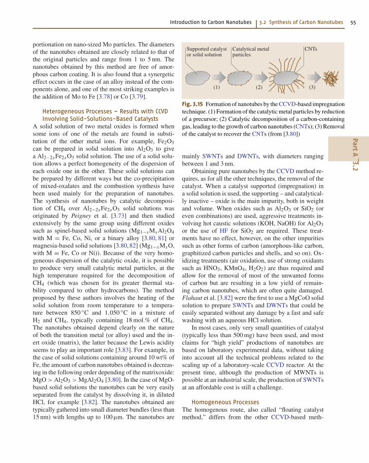
There are two main ways for the preparation of thecatalyst: (a) the impregnation of a substrate with a so-lution of a salt of the desired transition metal catalyst,and (b) the preparation of a solid solution of an oxideof the chosen catalytic metal in a chemically inert andthermally stable host oxide. The catalyst is then reducedto form the metal particles on which the catalytic de-composition of the carbon source will lead to carbonnanotube growth. In most cases, the nanotubes can thenbe separated from the catalyst (Fig. 3.15).
Heterogeneous Processes – Results with CCVDInvolving Impregnated Catalysts
A lot of work was already done in this area even beforethe discovery of fullerenes and carbon nanotubes, butalthough the formation of tubular carbon structures bycatalytic processes involving small metal particles wasclearly identified, the authors did not focus on the prepa-ration of SWNTs or MWNTs with respect to the othercarbon species. Some examples will be given here toillustrate the most striking improvements obtained.
With the impregnation method, the process generallyinvolves four different and successive steps: (1) the im-pregnation of the support by a solution of a salt (nitrate,chloride) of the chosen metal catalyst; (2) the drying andcalcination of the supported catalyst to get the oxide ofthe catalytic metal; (3) the reduction in a H2-containingatmosphere to make the catalytic metal particles and atlast (4) the decomposition of a carbon-containing gasover the freshly prepared metal particles that will lead tothe nanotube growth. For example, Ivanov et al. [3.74]have prepared nanotubes by the decomposition of C2H2(pure or in mixture with H2) on well-dispersed transitionmetal particles (Fe, Co, Ni, Cu) supported on graphite orSiO2. Co-SiO2 was found to be the best catalyst/supportcombination for the preparation of MWNTs, but most ofthe other combinations led to carbon filaments, some-times covered with amorphous-like carbon. The sameauthors have developed a precipitation-ion-exchangemethod that provides a better dispersion of metals onsilica compared to the classical impregnation technique.The same group has then proposed the use of a zeolite-supported Co catalyst [3.75,76], resulting in very finelydispersed metal particles (from 1 to 50 nm in diameter).Only on this catalyst could they observe MWNTs witha diameter around 4 nm and only two or three walls.Dai et al. [3.77] have prepared SWNTs by CO dispro-
PartA
3.2
Introduction to Carbon Nanotubes 3.2 Synthesis of Carbon Nanotubes 55
portionation on nano-sized Mo particles. The diametersof the nanotubes obtained are closely related to that ofthe original particles and range from 1 to 5 nm. Thenanotubes obtained by this method are free of amor-phous carbon coating. It is also found that a synergeticeffect occurs in the case of an alloy instead of the com-ponents alone, and one of the most striking examples isthe addition of Mo to Fe [3.78] or Co [3.79].
Heterogeneous Processes – Results with CCVDInvolving Solid-Solutions-Based Catalysts
A solid solution of two metal oxides is formed whensome ions of one of the metals are found in substi-tution of the other metal ions. For example, Fe2O3can be prepared in solid solution into Al2O3 to givea Al2−2xFe2xO3 solid solution. The use of a solid solu-tion allows a perfect homogeneity of the dispersion ofeach oxide one in the other. These solid solutions canbe prepared by different ways but the co-precipitationof mixed-oxalates and the combustion synthesis havebeen used mainly for the preparation of nanotubes.The synthesis of nanotubes by catalytic decomposi-tion of CH4 over Al2−2xFe2xO3 solid solutions wasoriginated by Peigney et al. [3.73] and then studiedextensively by the same group using different oxidessuch as spinel-based solid solutions (Mg1−xMxAl2O4with M = Fe, Co, Ni, or a binary alloy [3.80, 81] ormagnesia-based solid solutions [3.80,82] (Mg1−xMxO,with M = Fe, Co or Ni)). Because of the very homo-geneous dispersion of the catalytic oxide, it is possibleto produce very small catalytic metal particles, at thehigh temperature required for the decomposition ofCH4 (which was chosen for its greater thermal sta-bility compared to other hydrocarbons). The methodproposed by these authors involves the heating of thesolid solution from room temperature to a tempera-ture between 850 C and 1,050 C in a mixture ofH2 and CH4, typically containing 18 mol.% of CH4.The nanotubes obtained depend clearly on the natureof both the transition metal (or alloy) used and the in-ert oxide (matrix), the latter because the Lewis acidityseems to play an important role [3.83]. For example, inthe case of solid solutions containing around 10 wt% ofFe, the amount of carbon nanotubes obtained is decreas-ing in the following order depending of the matrixoxide:MgO > Al2O3 > MgAl2O4 [3.80]. In the case of MgO-based solid solutions the nanotubes can be very easilyseparated from the catalyst by dissolving it, in dilutedHCl, for example [3.82]. The nanotubes obtained aretypically gathered into small diameter bundles (less than15 nm) with lengths up to 100 µm. The nanotubes are
Supported catalystor solid solution
Catalytical metalparticles
CNTs
(1) (2) (3)
Fig. 3.15 Formation of nanotubes by the CCVD-based impregnationtechnique. (1) Formation of the catalytic metal particles by reductionof a precursor; (2) Catalytic decomposition of a carbon-containinggas, leading to the growth of carbon nanotubes (CNTs); (3) Removalof the catalyst to recover the CNTs (from [3.80])
mainly SWNTs and DWNTs, with diameters rangingbetween 1 and 3 nm.
Obtaining pure nanotubes by the CCVD method re-quires, as for all the other techniques, the removal of thecatalyst. When a catalyst supported (impregnation) ina solid solution is used, the supporting – and catalytical-ly inactive – oxide is the main impurity, both in weightand volume. When oxides such as Al2O3 or SiO2 (oreven combinations) are used, aggressive treatments in-volving hot caustic solutions (KOH, NaOH) for Al2O3or the use of HF for SiO2 are required. These treat-ments have no effect, however, on the other impuritiessuch as other forms of carbon (amorphous-like carbon,graphitized carbon particles and shells, and so on). Ox-idizing treatments (air oxidation, use of strong oxidantssuch as HNO3, KMnO4, H2O2) are thus required andallow for the removal of most of the unwanted formsof carbon but are resulting in a low yield of remain-ing carbon nanotubes, which are often quite damaged.Flahaut et al. [3.82] were the first to use a MgCoO solidsolution to prepare SWNTs and DWNTs that could beeasily separated without any damage by a fast and safewashing with an aqueous HCl solution.
In most cases, only very small quantities of catalyst(typically less than 500 mg) have been used, and mostclaims for “high yield” productions of nanotubes arebased on laboratory experimental data, without takinginto account all the technical problems related to thescaling up of a laboratory-scale CCVD reactor. At thepresent time, although the production of MWNTs ispossible at an industrial scale, the production of SWNTsat an affordable cost is still a challenge.
Homogeneous ProcessesThe homogenous route, also called “floating catalystmethod,” differs from the other CCVD-based meth-
PartA
3.2
56 Part A Nanostructures, Micro/Nanofabrication, and Micro/Nanodevices
ods because it uses only gaseous species and does notrequire the presence of any solid phase in the reac-tor. The basic principle of this technique, similar tothe other CCVD processes, is to decompose a carbonsource (ethylene, xylene, benzene, carbon monoxide,etc.) on nanometric transition metallic (generally Fe,Co, or Ni) particles in order to obtain carbon nano-tubes. The catalytic particles are formed directly in thereactor, however, and are not introduced before thereaction, as it happens in the supported CCVD, forinstance.
Homogeneous Processes –Experimental Devices
The typical reactor used in this technique is a quartztube placed in an oven to which the gaseous feedstock,containing the metal precursor, the carbon source, somehydrogen, and a vector gas (N2, Ar, or He), is sent.The first zone of the reactor is kept at a lower tem-perature, and the second zone, where the formation oftubes occurs, is heated to 700–1,200 C. The metal pre-cursor is generally a metal-organic compound, such asa zero-valent carbonyl compound like Fe(CO)5 [3.84],or a metallocene [3.85–87], for instance ferrocene, nick-elocene or cobaltocene. It may be advantageous to makethe reactor vertical, in order for the effect of gravity tobe symmetrically dispatched on the gaseous volume in-side the furnace and to help in maintaining for a whilethe solid products in fluidized bed.
Homogeneous Processes – ResultsThe metal-organic compound decomposes in the firstzone of the reactor to generate the nanometric metallicparticles that can catalyze the nanotubes formation. Inthe second part of the reactor, the carbon source is de-composed to atomic carbon which then is responsiblefor the formation of nanotubes.
This technique is quite flexible and both single-walled nanotubes [3.88] and multiwalled nano-tubes [3.89] have been obtained depending on thecarbon feedstock gas; it has also been exploited forsome years in the production of vapor grown carbonnanofibers [3.90].
The main drawback of this type of process is again,as for heterogeneous processes, the difficulty to controlthe size of the metal nanoparticles, and thus the nano-tube formation is often accompanied by the productionof undesired carbon forms (amorphous carbon or poly-aromatic carbon phases found as various phases or ascoatings). In particular, encapsulated forms have beenoften found, as the result of the creation of metallic par-
ticles that are too big to be active for growing nanotubes(but are still effective for catalytically decomposing thecarbon source) and be totally recovered by graphenelayers.
The same kind of parameters as for heterogeneousprocesses have to be controlled in order to finely tunethis process and obtain selectively the desired morphol-ogy and structure of the nanotubes formed, such as: thechoice of the carbon source; the reaction temperature;the residence time; the composition of the incominggaseous feedstock with a particular attention paid to therole played by hydrogen proportion, which can controlthe orientation of graphenes with respect to the nanotubeaxis thus switching from c-MWNT to h-MWNT [3.69];and the ratio of the metallorganic precursor to the carbonsource (for lower values, SWNTs are obtained [3.85]).As recently demonstrated, the overall process can beimproved by adding other compounds such as ammoniaor sulfur-containing species to the reactive gas phase.The former allows aligned nanotubes and mixed C-Nnanotubes [3.91] to be obtained, the latter results ina significant increase in productivity [3.90].
It should be emphasized that only small productionshave been achieved so far, and the scale up toward in-dustrial exploitation seems quite difficult because of thelarge number of parameters that have to be considered.A critical one is to be able to increase the quantity ofmetallorganic compound that has to be sent in the reac-tor, as a requirement to increase the production, withoutobtaining too big particles. This problem has not yetbeen solved. An additional problem inherent in the pro-cess is the possibility of clogging the reactor due to thedeposition of metallic nanoparticles on the reactor wallsfollowed by carbon deposition.
A significant breakthrough concerning this tech-nique could be the process developed at Rice University,the so-called HiPCoTM process to produce SWNTs ofvery high purity [3.92]. This gas phase catalytic reac-tion uses carbon monoxide to produce, from [Fe(CO)5],a SWNT material claimed to be relatively free ofby-products. The temperature and pressure conditionsrequired are applicable to industrial plants. The companyCarbon Nanotechnologies Inc. (Houston, TX, USA) ac-tually sells raw SWNT materials prepared that way,at a marketed price of $ 375/g, doubled if purified(2003 data). Other companies are more specialized inMWNTs such as Applied Sciences Inc. (Cedarville,Ohio, USA), which currently has a production facility of∼ 40 tons/year of ∼ 100 nm large MWNTs (Pyrograf-III), or Hyperion Catalysis (Cambridge, MA, USA),which makes MWNT-based materials.
PartA
3.2
Introduction to Carbon Nanotubes 3.2 Synthesis of Carbon Nanotubes 57
TemplatingAnother technique interesting to describe briefly, thoughdefinitely not suitable for mass production, is the tem-plating technique. It is the second method only (thefirst being the electric-arc technique, when consider-ing the formation of MWNTs on the cathode) ableto synthesize carbon nanotubes without any catalyst.Any other work reporting the catalyst-free formationof nanotubes is likely to have been fooled by metal-lic impurities present in the reactor or by some otherfactors having brought a chemical gradient to the sys-tem. Another original aspect is that it allows alignednanotubes to be obtained naturally, without the helpof any subsequent alignment procedure. But recoveringthe nanotubes only requires the template to be removed(dissolved), which means the former alignment of thenanotubes is lost.
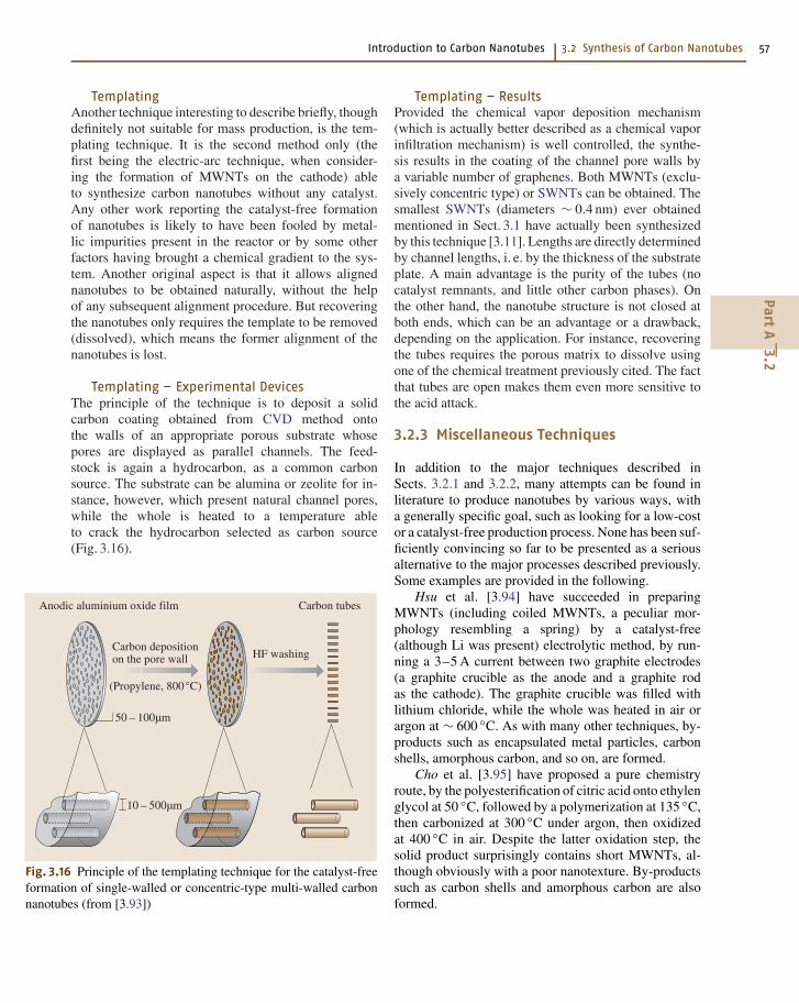
Templating – Experimental DevicesThe principle of the technique is to deposit a solidcarbon coating obtained from CVD method ontothe walls of an appropriate porous substrate whosepores are displayed as parallel channels. The feed-stock is again a hydrocarbon, as a common carbonsource. The substrate can be alumina or zeolite for in-stance, however, which present natural channel pores,while the whole is heated to a temperature ableto crack the hydrocarbon selected as carbon source(Fig. 3.16).
Anodic aluminium oxide film
Carbon depositionon the pore wall HF washing
Carbon tubes
(Propylene, 800°C)
50 – 100µm
10 – 500µm
Fig. 3.16 Principle of the templating technique for the catalyst-freeformation of single-walled or concentric-type multi-walled carbonnanotubes (from [3.93])
Templating – ResultsProvided the chemical vapor deposition mechanism(which is actually better described as a chemical vaporinfiltration mechanism) is well controlled, the synthe-sis results in the coating of the channel pore walls bya variable number of graphenes. Both MWNTs (exclu-sively concentric type) or SWNTs can be obtained. Thesmallest SWNTs (diameters ∼ 0.4 nm) ever obtainedmentioned in Sect. 3.1 have actually been synthesizedby this technique [3.11]. Lengths are directly determinedby channel lengths, i. e. by the thickness of the substrateplate. A main advantage is the purity of the tubes (nocatalyst remnants, and little other carbon phases). Onthe other hand, the nanotube structure is not closed atboth ends, which can be an advantage or a drawback,depending on the application. For instance, recoveringthe tubes requires the porous matrix to dissolve usingone of the chemical treatment previously cited. The factthat tubes are open makes them even more sensitive tothe acid attack.
3.2.3 Miscellaneous Techniques
In addition to the major techniques described inSects. 3.2.1 and 3.2.2, many attempts can be found inliterature to produce nanotubes by various ways, witha generally specific goal, such as looking for a low-costor a catalyst-free production process. None has been suf-ficiently convincing so far to be presented as a seriousalternative to the major processes described previously.Some examples are provided in the following.
Hsu et al. [3.94] have succeeded in preparingMWNTs (including coiled MWNTs, a peculiar mor-phology resembling a spring) by a catalyst-free(although Li was present) electrolytic method, by run-ning a 3–5 A current between two graphite electrodes(a graphite crucible as the anode and a graphite rodas the cathode). The graphite crucible was filled withlithium chloride, while the whole was heated in air orargon at ∼ 600 C. As with many other techniques, by-products such as encapsulated metal particles, carbonshells, amorphous carbon, and so on, are formed.
Cho et al. [3.95] have proposed a pure chemistryroute, by the polyesterification of citric acid onto ethylenglycol at 50 C, followed by a polymerization at 135 C,then carbonized at 300 C under argon, then oxidizedat 400 C in air. Despite the latter oxidation step, thesolid product surprisingly contains short MWNTs, al-though obviously with a poor nanotexture. By-productssuch as carbon shells and amorphous carbon are alsoformed.
PartA
3.2
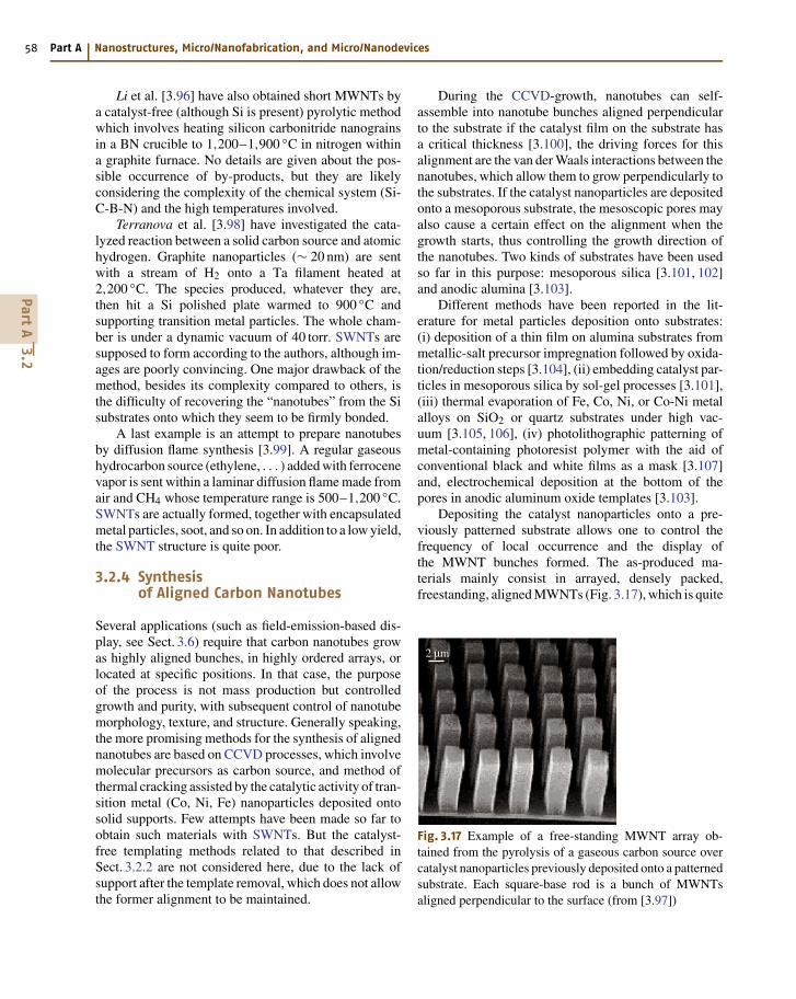
58 Part A Nanostructures, Micro/Nanofabrication, and Micro/Nanodevices
Li et al. [3.96] have also obtained short MWNTs bya catalyst-free (although Si is present) pyrolytic methodwhich involves heating silicon carbonitride nanograinsin a BN crucible to 1,200–1,900 C in nitrogen withina graphite furnace. No details are given about the pos-sible occurrence of by-products, but they are likelyconsidering the complexity of the chemical system (Si-C-B-N) and the high temperatures involved.
Terranova et al. [3.98] have investigated the cata-lyzed reaction between a solid carbon source and atomichydrogen. Graphite nanoparticles (∼ 20 nm) are sentwith a stream of H2 onto a Ta filament heated at2,200 C. The species produced, whatever they are,then hit a Si polished plate warmed to 900 C andsupporting transition metal particles. The whole cham-ber is under a dynamic vacuum of 40 torr. SWNTs aresupposed to form according to the authors, although im-ages are poorly convincing. One major drawback of themethod, besides its complexity compared to others, isthe difficulty of recovering the “nanotubes” from the Sisubstrates onto which they seem to be firmly bonded.
A last example is an attempt to prepare nanotubesby diffusion flame synthesis [3.99]. A regular gaseoushydrocarbon source (ethylene, . . . ) added with ferrocenevapor is sent within a laminar diffusion flame made fromair and CH4 whose temperature range is 500–1,200 C.SWNTs are actually formed, together with encapsulatedmetal particles, soot, and so on. In addition to a low yield,the SWNT structure is quite poor.
3.2.4 Synthesisof Aligned Carbon Nanotubes
Several applications (such as field-emission-based dis-play, see Sect. 3.6) require that carbon nanotubes growas highly aligned bunches, in highly ordered arrays, orlocated at specific positions. In that case, the purposeof the process is not mass production but controlledgrowth and purity, with subsequent control of nanotubemorphology, texture, and structure. Generally speaking,the more promising methods for the synthesis of alignednanotubes are based on CCVD processes, which involvemolecular precursors as carbon source, and method ofthermal cracking assisted by the catalytic activity of tran-sition metal (Co, Ni, Fe) nanoparticles deposited ontosolid supports. Few attempts have been made so far toobtain such materials with SWNTs. But the catalyst-free templating methods related to that described inSect. 3.2.2 are not considered here, due to the lack ofsupport after the template removal, which does not allowthe former alignment to be maintained.
During the CCVD-growth, nanotubes can self-assemble into nanotube bunches aligned perpendicularto the substrate if the catalyst film on the substrate hasa critical thickness [3.100], the driving forces for thisalignment are the van der Waals interactions between thenanotubes, which allow them to grow perpendicularly tothe substrates. If the catalyst nanoparticles are depositedonto a mesoporous substrate, the mesoscopic pores mayalso cause a certain effect on the alignment when thegrowth starts, thus controlling the growth direction ofthe nanotubes. Two kinds of substrates have been usedso far in this purpose: mesoporous silica [3.101, 102]and anodic alumina [3.103].
Different methods have been reported in the lit-erature for metal particles deposition onto substrates:(i) deposition of a thin film on alumina substrates frommetallic-salt precursor impregnation followed by oxida-tion/reduction steps [3.104], (ii) embedding catalyst par-ticles in mesoporous silica by sol-gel processes [3.101],(iii) thermal evaporation of Fe, Co, Ni, or Co-Ni metalalloys on SiO2 or quartz substrates under high vac-uum [3.105, 106], (iv) photolithographic patterning ofmetal-containing photoresist polymer with the aid ofconventional black and white films as a mask [3.107]and, electrochemical deposition at the bottom of thepores in anodic aluminum oxide templates [3.103].
Depositing the catalyst nanoparticles onto a pre-viously patterned substrate allows one to control thefrequency of local occurrence and the display ofthe MWNT bunches formed. The as-produced ma-terials mainly consist in arrayed, densely packed,freestanding, aligned MWNTs (Fig. 3.17), which is quite
2 µm
Fig. 3.17 Example of a free-standing MWNT array ob-tained from the pyrolysis of a gaseous carbon source overcatalyst nanoparticles previously deposited onto a patternedsubstrate. Each square-base rod is a bunch of MWNTsaligned perpendicular to the surface (from [3.97])
PartA
3.2
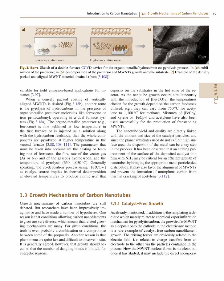
Introduction to Carbon Nanotubes 3.3 Growth Mechanisms of Carbon Nanotubes 59
a) b)
50µmLow-temperature oven High-temperature oven
Fig. 3.18a–c Sketch of a double-furnace CCVD device for the organo-metallic/hydrocarbon co-pyrolysis process. In (a): subli-mation of the precursor; in (b): decomposition of the precursor and MWNTs growth onto the substrate. (c) Example of the denselypacked and aligned MWNT material obtained (from [3.108])
suitable for field emission-based applications for in-stance [3.97].
When a densely packed coating of verticallyaligned MWNTs is desired (Fig. 3.18b), another routeis the pyrolysis of hydrocarbons in the presence oforganometallic precursor molecules like ferrocene oriron pentacarbonyl, operating in a dual furnace sys-tem (Fig. 3.18a). The organo-metallic precursor (e.g.,ferrocene) is first sublimed at low temperature inthe first furnace or is injected as a solution alongwith the hydrocarbon feedstock, then the whole com-ponents are pyrolyzed at higher temperature in thesecond furnace [3.88, 108–111]. The parameters thatmust be taken into account are the heating or feed-ing rate of ferrocene, the flow rate of the vector gas(Ar or N2) and of the gaseous hydrocarbon, and thetemperature of pyrolysis (650–1,050 C). Generallyspeaking, the co-deposition process using [Fe(CO)5]as catalyst source implies its thermal decompositionat elevated temperatures to produce atomic iron that
deposits on the substrates in the hot zone of the re-actor. As the nanotube growth occurs simultaneouslywith the introduction of [Fe(CO)5], the temperatureschosen for the growth depend on the carbon feedstockutilized, e.g., they can vary from 750 C for acety-lene to 1,100 C for methane. Mixtures of [FeCp2]and xylene or [FeCp2] and acetylene have also beenused successfully for the production of freestandingMWNTs.
The nanotube yield and quality are directly linkedwith the amount and size of the catalyst particles, andsince the planar substrates used do not exhibit high sur-face area, the dispersion of the metal can be a key stepin the process. It has been observed that an etching pre-treatment of the surface of the deposited catalyst thinfilm with NH3 may be critical for an efficient growth ofnanotubes by bringing the appropriate metal particle sizedistribution. It may also favor the alignment of MWNTsand prevent the formation of amorphous carbon fromthermal cracking of acetylene [3.112].
3.3 Growth Mechanisms of Carbon Nanotubes
Growth mechanisms of carbon nanotubes are stilldebated. But researchers have been impressively im-aginative and have made a number of hypotheses. Onereason is that conditions allowing carbon nanofilamentsto grow are very diverse, which means that related grow-ing mechanisms are many. For given conditions, thetruth is even probably a combination or a compromisebetween some of the proposals. Another reason is thatphenomena are quite fast and difficult to observe in situ.It is generally agreed, however, that growth should oc-cur so that the number of dangling bonds is limited, forenergetic reasons.
3.3.1 Catalyst-Free Growth
As already mentioned, in addition to the templating tech-nique which merely relates to chemical vapor infiltrationmechanism for pyrolytic carbon, the growth of c-MWNTas a deposit onto the cathode in the electric-arc methodis a rare example of catalyst-free carbon nanofilamentgrowth. The driving forces are obviously related to theelectric field, i. e. related to charge transfers from anelectrode to the other via the particles contained in theplasma. How the MWNT nucleus forms is not clear, butonce it has started, it may include the direct incorpora-
PartA
3.3
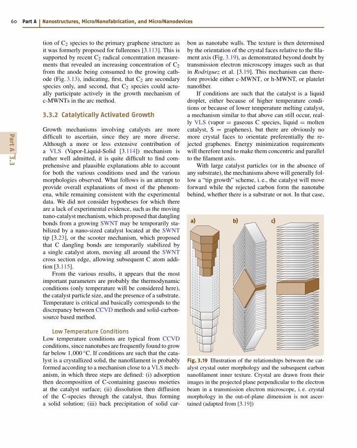
60 Part A Nanostructures, Micro/Nanofabrication, and Micro/Nanodevices
tion of C2 species to the primary graphene structure asit was formerly proposed for fullerenes [3.113]. This issupported by recent C2 radical concentration measure-ments that revealed an increasing concentration of C2from the anode being consumed to the growing cath-ode (Fig. 3.13), indicating, first, that C2 are secondaryspecies only, and second, that C2 species could actu-ally participate actively in the growth mechanism ofc-MWNTs in the arc method.
3.3.2 Catalytically Activated Growth
Growth mechanisms involving catalysts are moredifficult to ascertain, since they are more diverse.Although a more or less extensive contribution ofa VLS (Vapor-Liquid-Solid [3.114]) mechanism israther well admitted, it is quite difficult to find com-prehensive and plausible explanations able to accountfor both the various conditions used and the variousmorphologies observed. What follows is an attempt toprovide overall explanations of most of the phenom-ena, while remaining consistent with the experimentaldata. We did not consider hypotheses for which thereare a lack of experimental evidence, such as the movingnano-catalyst mechanism, which proposed that danglingbonds from a growing SWNT may be temporarily sta-bilized by a nano-sized catalyst located at the SWNTtip [3.23], or the scooter mechanism, which proposedthat C dangling bonds are temporarily stabilized bya single catalyst atom, moving all around the SWNTcross section edge, allowing subsequent C atom addi-tion [3.115].
From the various results, it appears that the mostimportant parameters are probably the thermodynamicconditions (only temperature will be considered here),the catalyst particle size, and the presence of a substrate.Temperature is critical and basically corresponds to thediscrepancy between CCVD methods and solid-carbon-source based method.
Low Temperature ConditionsLow temperature conditions are typical from CCVDconditions, since nanotubes are frequently found to growfar below 1,000 C. If conditions are such that the cata-lyst is a crystallized solid, the nanofilament is probablyformed according to a mechanism close to a VLS mech-anism, in which three steps are defined: (i) adsorptionthen decomposition of C-containing gaseous moietiesat the catalyst surface; (ii) dissolution then diffusionof the C-species through the catalyst, thus forminga solid solution; (iii) back precipitation of solid car-
bon as nanotube walls. The texture is then determinedby the orientation of the crystal faces relative to the fila-ment axis (Fig. 3.19), as demonstrated beyond doubt bytransmission electron microscopy images such as thatin Rodriguez et al. [3.19]. This mechanism can there-fore provide either c-MWNT, or h-MWNT, or plateletnanofiber.
If conditions are such that the catalyst is a liquiddroplet, either because of higher temperature condi-tions or because of lower temperature melting catalyst,a mechanism similar to that above can still occur, real-ly VLS (vapor = gaseous C species, liquid = moltencatalyst, S = graphenes), but there are obviously nomore crystal faces to orientate preferentially the re-jected graphenes. Energy minimization requirementswill therefore tend to make them concentric and parallelto the filament axis.
With large catalyst particles (or in the absence ofany substrate), the mechanisms above will generally fol-low a “tip growth” scheme, i. e., the catalyst will moveforward while the rejected carbon form the nanotubebehind, whether there is a substrate or not. In that case,
a) b) c)
Fig. 3.19 Illustration of the relationships between the cat-alyst crystal outer morphology and the subsequent carbonnanofilament inner texture. Crystal are drawn from theirimages in the projected plane perpendicular to the electronbeam in a transmission electron microscope, i. e. crystalmorphology in the out-of-plane dimension is not ascer-tained (adapted from [3.19])
PartA
3.3
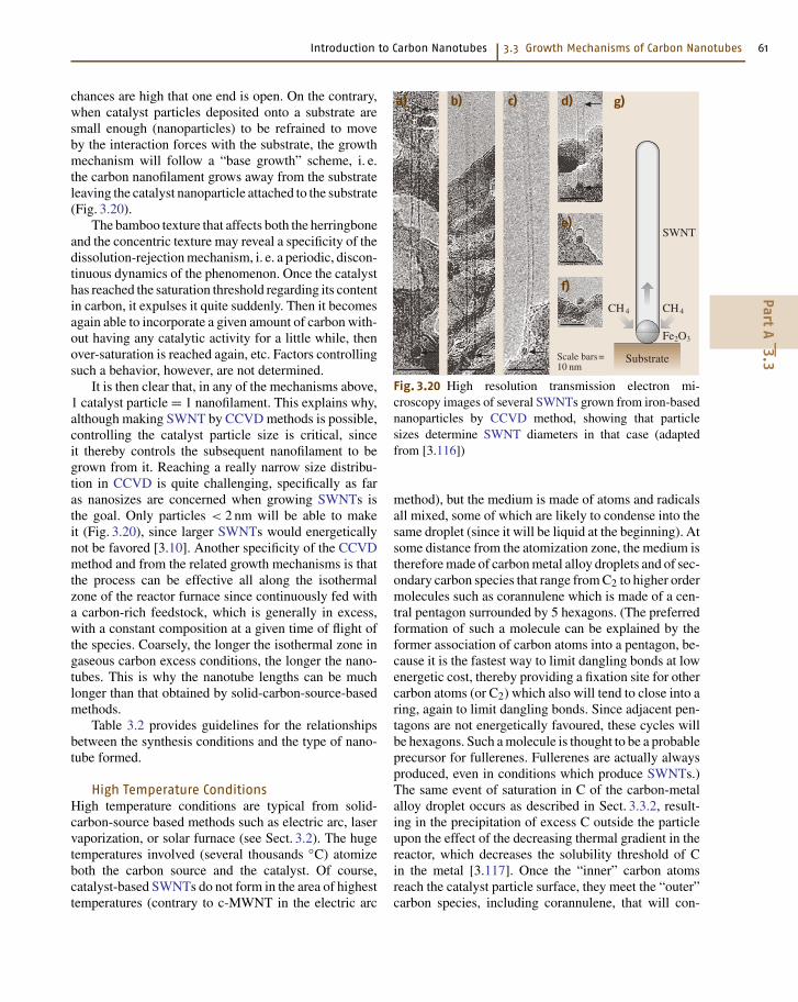
Introduction to Carbon Nanotubes 3.3 Growth Mechanisms of Carbon Nanotubes 61
chances are high that one end is open. On the contrary,when catalyst particles deposited onto a substrate aresmall enough (nanoparticles) to be refrained to moveby the interaction forces with the substrate, the growthmechanism will follow a “base growth” scheme, i. e.the carbon nanofilament grows away from the substrateleaving the catalyst nanoparticle attached to the substrate(Fig. 3.20).
The bamboo texture that affects both the herringboneand the concentric texture may reveal a specificity of thedissolution-rejection mechanism, i. e. a periodic, discon-tinuous dynamics of the phenomenon. Once the catalysthas reached the saturation threshold regarding its contentin carbon, it expulses it quite suddenly. Then it becomesagain able to incorporate a given amount of carbon with-out having any catalytic activity for a little while, thenover-saturation is reached again, etc. Factors controllingsuch a behavior, however, are not determined.
It is then clear that, in any of the mechanisms above,1 catalyst particle = 1 nanofilament. This explains why,although making SWNT by CCVD methods is possible,controlling the catalyst particle size is critical, sinceit thereby controls the subsequent nanofilament to begrown from it. Reaching a really narrow size distribu-tion in CCVD is quite challenging, specifically as faras nanosizes are concerned when growing SWNTs isthe goal. Only particles < 2 nm will be able to makeit (Fig. 3.20), since larger SWNTs would energeticallynot be favored [3.10]. Another specificity of the CCVDmethod and from the related growth mechanisms is thatthe process can be effective all along the isothermalzone of the reactor furnace since continuously fed witha carbon-rich feedstock, which is generally in excess,with a constant composition at a given time of flight ofthe species. Coarsely, the longer the isothermal zone ingaseous carbon excess conditions, the longer the nano-tubes. This is why the nanotube lengths can be muchlonger than that obtained by solid-carbon-source-basedmethods.
Table 3.2 provides guidelines for the relationshipsbetween the synthesis conditions and the type of nano-tube formed.
High Temperature ConditionsHigh temperature conditions are typical from solid-carbon-source based methods such as electric arc, laservaporization, or solar furnace (see Sect. 3.2). The hugetemperatures involved (several thousands C) atomizeboth the carbon source and the catalyst. Of course,catalyst-based SWNTs do not form in the area of highesttemperatures (contrary to c-MWNT in the electric arc
SWNT
CH4
Fe2O3
CH4
Substrate
a) b) c) d)
e)
f)
g)
Scale bars=10 nm
Fig. 3.20 High resolution transmission electron mi-croscopy images of several SWNTs grown from iron-basednanoparticles by CCVD method, showing that particlesizes determine SWNT diameters in that case (adaptedfrom [3.116])
method), but the medium is made of atoms and radicalsall mixed, some of which are likely to condense into thesame droplet (since it will be liquid at the beginning). Atsome distance from the atomization zone, the medium istherefore made of carbon metal alloy droplets and of sec-ondary carbon species that range from C2 to higher ordermolecules such as corannulene which is made of a cen-tral pentagon surrounded by 5 hexagons. (The preferredformation of such a molecule can be explained by theformer association of carbon atoms into a pentagon, be-cause it is the fastest way to limit dangling bonds at lowenergetic cost, thereby providing a fixation site for othercarbon atoms (or C2) which also will tend to close into aring, again to limit dangling bonds. Since adjacent pen-tagons are not energetically favoured, these cycles willbe hexagons. Such a molecule is thought to be a probableprecursor for fullerenes. Fullerenes are actually alwaysproduced, even in conditions which produce SWNTs.)The same event of saturation in C of the carbon-metalalloy droplet occurs as described in Sect. 3.3.2, result-ing in the precipitation of excess C outside the particleupon the effect of the decreasing thermal gradient in thereactor, which decreases the solubility threshold of Cin the metal [3.117]. Once the “inner” carbon atomsreach the catalyst particle surface, they meet the “outer”carbon species, including corannulene, that will con-
PartA
3.3
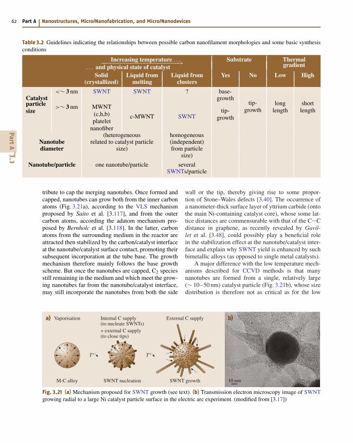
62 Part A Nanostructures, Micro/Nanofabrication, and Micro/Nanodevices
Table 3.2 Guidelines indicating the relationships between possible carbon nanofilament morphologies and some basic synthesisconditions
Increasing temperature . . . Substrate Thermal−−−−−−−−−−−−−−−−−−−−−−−→ gradient. . . and physical state of catalystSolid Liquid from Liquid from Yes No Low High
(crystallized) melting clusters
<∼ 3 nm SWNT SWNT ? base-Catalyst growthparticlesize
>∼ 3 nm MWNT(c,h,b)platelet
nanofiber
c-MWNT SWNTtip-
growth
tip-growth
longlength
shortlength
(heterogeneous homogeneousNanotube related to catalyst particle (independent)diameter size) from particle
size)
Nanotube/particle one nanotube/particle severalSWNTs/particle
tribute to cap the merging nanotubes. Once formed andcapped, nanotubes can grow both from the inner carbonatoms (Fig. 3.21a), according to the VLS mechanismproposed by Saito et al. [3.117], and from the outercarbon atoms, according the adatom mechanism pro-posed by Bernholc et al. [3.118]. In the latter, carbonatoms from the surrounding medium in the reactor areattracted then stabilized by the carbon/catalyst interfaceat the nanotube/catalyst surface contact, promoting theirsubsequent incorporation at the tube base. The growthmechanism therefore mainly follows the base growthscheme. But once the nanotubes are capped, C2 speciesstill remaining in the medium and which meet the grow-ing nanotubes far from the nanotube/catalyst interface,may still incorporate the nanotubes from both the side
Vaporisation
M-C alloy
T°
External C supply
SWNT growth
T°
Internal C supply(to nucleate SWNTs)+ external C supply(to close tips)
SWNT nucleation
a) b)
10 nm
Fig. 3.21 (a) Mechanism proposed for SWNT growth (see text). (b) Transmission electron microscopy image of SWNTgrowing radial to a large Ni catalyst particle surface in the electric arc experiment. (modified from [3.17])
wall or the tip, thereby giving rise to some propor-tion of Stone–Wales defects [3.40]. The occurrence ofa nanometer-thick surface layer of yttrium carbide (ontothe main Ni-containing catalyst core), whose some lat-tice distances are commensurable with that of the C−Cdistance in graphene, as recently revealed by Gavil-let et al. [3.48], could possibly play a beneficial rolein the stabilization effect at the nanotube/catalyst inter-face and explain why SWNT yield is enhanced by suchbimetallic alloys (as opposed to single metal catalysts).
A major difference with the low temperature mech-anisms described for CCVD methods is that manynanotubes are formed from a single, relatively large(∼ 10–50 nm) catalyst particle (Fig. 3.21b), whose sizedistribution is therefore not as critical as for the low
PartA
3.3
Introduction to Carbon Nanotubes 3.4 Properties of Carbon Nanotubes 63
temperature mechanisms (particles that are too large,however, would induce polyaromatic shells instead ofnanotubes). That is why SWNT diameters are muchmore homogeneous than for CCVD methods. Why themost frequent diameter is ∼ 1.4 nm is again a matterof energy balance. Single-wall nanotubes larger than∼ 2.5 nm are not stable [3.10]. On the other hand, strainto the C−C angles increases as the radius of curva-ture decreases. Such diameter (1.4 nm) should thereforecorrespond to the best energetic compromise. Anotherdifference with the low temperature mechanisms forCCVD is that temperature gradients are huge, and the gasphase composition surrounding the catalysts droplets isalso subjected to rapid changes (as opposed to what
could happen in a laminar flow of a gaseous feedstockwhose carbon source is in excess). This explains whynanotubes from arc are generally shorter than nanotubesfrom CCVD, and why mass production by CCVD shouldbe favored. In the latter, the catalytic role of the metal-lic particle can be recurrent as long as the conditionsare maintained. In the former, surrounding conditionschange continuously, and the window for efficient catal-ysis effect can be very narrow. Lowering temperaturegradients in solid carbon source-based SWNT producingmethods such as the electric-arc reactor should thereforebe a way to increase the SWNT yield and length [3.119].Amazingly, this is in opposition to fullerene productionfrom arc.
3.4 Properties of Carbon Nanotubes
Carbon is a unique light atom that can form one-, two-,or threefold strong chemical bonds. The planar threefoldconfiguration forms graphene planes that can, under cer-tain growth conditions (see Sect. 3.3), adopt a tubulargeometry. Properties of the so-called carbon nanotubesmay change drastically depending on whether SWNTsor MWNTs are considered (see Sect. 3.1).
3.4.1 Variabilityof Carbon Nanotube Properties
Properties of MWNTs are generally not much differ-ent from that of regular polyaromatic solids (which mayexhibit graphitic, or turbostratic, or intermediate crys-tallographic structure), and variations are then mainlydriven by the textural type of the MWNTs consid-ered (concentric, herringbone, bamboo) and the qualityof the nanotexture (see Sect. 3.1), both of which con-trol the extent of anisotropy. Actually, for polyaromaticsolids, whose structural entities are built with stackedgraphenes, bond strength is quite different dependingon whether the in-plane direction is considered (whichincludes only very strong – covalent – and thereforevery short – 0.142 nm bonds) or the direction perpen-dicular to it (which includes only very weak – van derWaals – and therefore very loose – ∼ 0.34 nm bonds).Such heterogeneity is not found in single (isolated)SWNTs. But the heterogeneity is back along with therelated consequences when SWNTs associate into bun-dles. Therefore, properties – and applicability – forSWNTs may also change dramatically depending onwhether single SWNT or SWNT ropes are involved.
In the following, we will emphasize SWNT prop-erties, as far as their original structure often leadsto original properties with respect to that of regularpolyaromatic solids. But we will also sometimes citeproperties of MWNTs for comparison.
3.4.2 General Properties
SWNT-type carbon nanotube diameters fall in thenanometer range and can be hundreds of micrometerslong. SWNTs are narrower in diameter than the thinnestline able to be obtained by electron beam lithography.SWNTs are stable up to 750 C in air (but start be-ing damaged earlier through oxidation mechanisms, asdemonstrated by their subsequent ability to be filled withmolecules, see Sect. 3.5) and up to ∼ 1,500–1,800 C ininert atmosphere beyond which they transform into reg-ular, polyaromatic solids (i. e., phases built with stackedgraphenes instead of single graphenes) [3.120]. Theyhave half the mass density of aluminum. While thelength of SWNTs can be macroscopic, the diameter hasa molecular dimension. As a molecule, properties areclosely influenced by the way atoms are displayed alongthe molecule direction. The physical and chemical be-havior of SWNTs are therefore related to their uniquestructural features [3.121].
3.4.3 SWNT Adsorption Properties
An interesting feature of SWNTs is their very high sur-face area, the highest ever due to the fact that a singlegraphene sheet is probably the unique example of a ma-
PartA
3.4
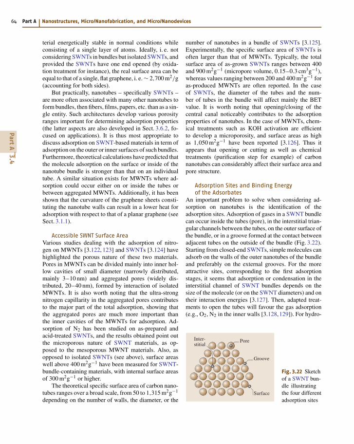
64 Part A Nanostructures, Micro/Nanofabrication, and Micro/Nanodevices
terial energetically stable in normal conditions whileconsisting of a single layer of atoms. Ideally, i. e. notconsidering SWNTs in bundles but isolated SWNTs, andprovided the SWNTs have one end opened (by oxida-tion treatment for instance), the real surface area can beequal to that of a single, flat graphene, i. e. ∼ 2,700 m2/g(accounting for both sides).
But practically, nanotubes – specifically SWNTs –are more often associated with many other nanotubes toform bundles, then fibers, films, papers, etc. than as a sin-gle entity. Such architectures develop various porosityranges important for determining adsorption properties(the latter aspects are also developed in Sect. 3.6.2, fo-cused on applications). It is thus most appropriate todiscuss adsorption on SWNT-based materials in term ofadsorption on the outer or inner surfaces of such bundles.Furthermore, theoretical calculations have predicted thatthe molecule adsorption on the surface or inside of thenanotube bundle is stronger than that on an individualtube. A similar situation exists for MWNTs where ad-sorption could occur either on or inside the tubes orbetween aggregated MWNTs. Additionally, it has beenshown that the curvature of the graphene sheets consti-tuting the nanotube walls can result in a lower heat foradsorption with respect to that of a planar graphene (seeSect. 3.1.1).
Accessible SWNT Surface AreaVarious studies dealing with the adsorption of nitro-gen on MWNTs [3.122, 123] and SWNTs [3.124] havehighlighted the porous nature of these two materials.Pores in MWNTs can be divided mainly into inner hol-low cavities of small diameter (narrowly distributed,mainly 3–10 nm) and aggregated pores (widely dis-tributed, 20–40 nm), formed by interaction of isolatedMWNTs. It is also worth noting that the ultra-strongnitrogen capillarity in the aggregated pores contributesto the major part of the total adsorption, showing thatthe aggregated pores are much more important thanthe inner cavities of the MWNTs for adsorption. Ad-sorption of N2 has been studied on as-prepared andacid-treated SWNTs, and the results obtained point outthe microporous nature of SWNT materials, as op-posed to the mesoporous MWNT materials. Also, asopposed to isolated SWNTs (see above), surface areaswell above 400 m2g−1 have been measured for SWNT-bundle-containing materials, with internal surface areasof 300 m2g−1 or higher.
The theoretical specific surface area of carbon nano-tubes ranges over a broad scale, from 50 to 1,315 m2g−1
depending on the number of walls, the diameter, or the
number of nanotubes in a bundle of SWNTs [3.125].Experimentally, the specific surface area of SWNTs isoften larger than that of MWNTs. Typically, the totalsurface area of as-grown SWNTs ranges between 400and 900 m2g−1 (micropore volume, 0.15–0.3 cm3g−1),whereas values ranging between 200 and 400 m2g−1 foras-produced MWNTs are often reported. In the caseof SWNTs, the diameter of the tubes and the num-ber of tubes in the bundle will affect mainly the BETvalue. It is worth noting that opening/closing of thecentral canal noticeably contributes to the adsorptionproperties of nanotubes. In the case of MWNTs, chem-ical treatments such as KOH activation are efficientto develop a microporosity, and surface areas as highas 1,050 m2g−1 have been reported [3.126]. Thus itappears that opening or cutting as well as chemicaltreatments (purification step for example) of carbonnanotubes can considerably affect their surface area andpore structure.
Adsorption Sites and Binding Energyof the Adsorbates
An important problem to solve when considering ad-sorption on nanotubes is the identification of theadsorption sites. Adsorption of gases in a SWNT bundlecan occur inside the tubes (pore), in the interstitial trian-gular channels between the tubes, on the outer surface ofthe bundle, or in a groove formed at the contact betweenadjacent tubes on the outside of the bundle (Fig. 3.22).Starting from closed-end SWNTs, simple molecules canadsorb on the walls of the outer nanotubes of the bundleand preferably on the external grooves. For the moreattractive sites, corresponding to the first adsorptionstages, it seems that adsorption or condensation in theinterstitial channel of SWNT bundles depends on thesize of the molecule (or on the SWNT diameters) and ontheir interaction energies [3.127]. Then, adapted treat-ments to open the tubes will favour the gas adsorption(e.g., O2, N2 in the inner walls [3.128,129]). For hydro-
Inter-stitial
Surface
Groove
Pore
Fig. 3.22 Sketchof a SWNT bun-dle illustratingthe four differentadsorption sites
PartA
3.4
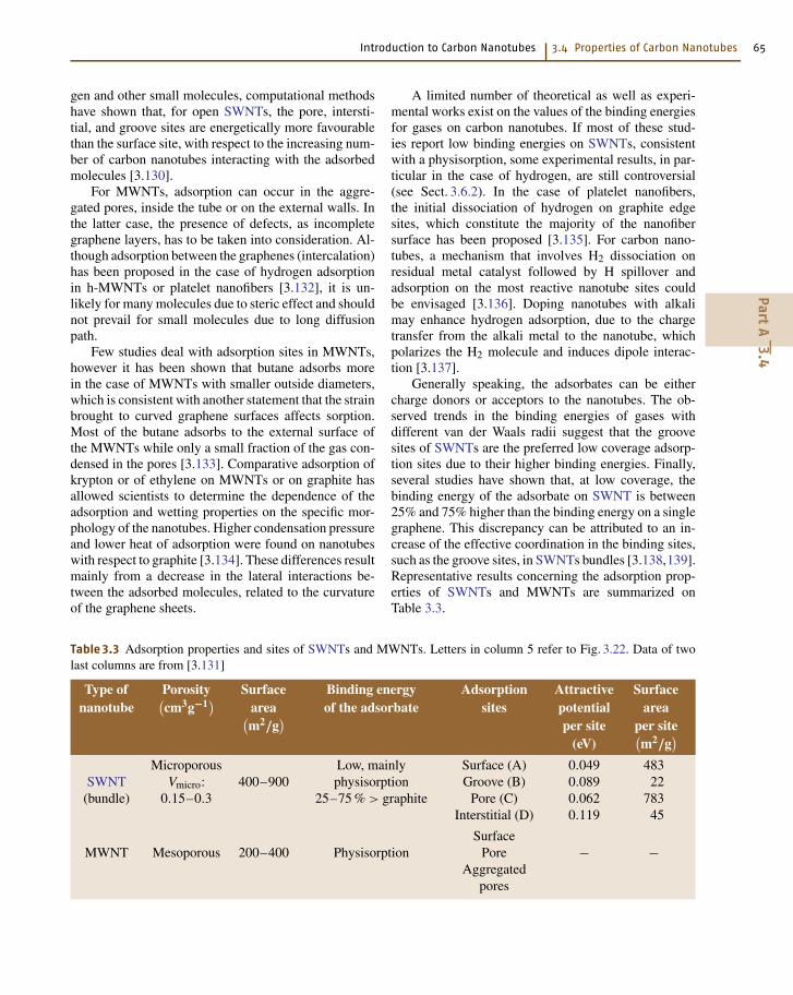
Introduction to Carbon Nanotubes 3.4 Properties of Carbon Nanotubes 65
gen and other small molecules, computational methodshave shown that, for open SWNTs, the pore, intersti-tial, and groove sites are energetically more favourablethan the surface site, with respect to the increasing num-ber of carbon nanotubes interacting with the adsorbedmolecules [3.130].
For MWNTs, adsorption can occur in the aggre-gated pores, inside the tube or on the external walls. Inthe latter case, the presence of defects, as incompletegraphene layers, has to be taken into consideration. Al-though adsorption between the graphenes (intercalation)has been proposed in the case of hydrogen adsorptionin h-MWNTs or platelet nanofibers [3.132], it is un-likely for many molecules due to steric effect and shouldnot prevail for small molecules due to long diffusionpath.
Few studies deal with adsorption sites in MWNTs,however it has been shown that butane adsorbs morein the case of MWNTs with smaller outside diameters,which is consistent with another statement that the strainbrought to curved graphene surfaces affects sorption.Most of the butane adsorbs to the external surface ofthe MWNTs while only a small fraction of the gas con-densed in the pores [3.133]. Comparative adsorption ofkrypton or of ethylene on MWNTs or on graphite hasallowed scientists to determine the dependence of theadsorption and wetting properties on the specific mor-phology of the nanotubes. Higher condensation pressureand lower heat of adsorption were found on nanotubeswith respect to graphite [3.134]. These differences resultmainly from a decrease in the lateral interactions be-tween the adsorbed molecules, related to the curvatureof the graphene sheets.
Table 3.3 Adsorption properties and sites of SWNTs and MWNTs. Letters in column 5 refer to Fig. 3.22. Data of twolast columns are from [3.131]
Type of Porosity Surface Binding energy Adsorption Attractive Surfacenanotube
(cm3g−1) area of the adsorbate sites potential area(
m2/g)
per site per site(eV)
(m2/g
)
Microporous Low, mainly Surface (A) 0.049 483SWNT Vmicro: 400–900 physisorption Groove (B) 0.089 22
(bundle) 0.15–0.3 25–75 % > graphite Pore (C) 0.062 783Interstitial (D) 0.119 45
SurfaceMWNT Mesoporous 200–400 Physisorption Pore − −
Aggregatedpores
A limited number of theoretical as well as experi-mental works exist on the values of the binding energiesfor gases on carbon nanotubes. If most of these stud-ies report low binding energies on SWNTs, consistentwith a physisorption, some experimental results, in par-ticular in the case of hydrogen, are still controversial(see Sect. 3.6.2). In the case of platelet nanofibers,the initial dissociation of hydrogen on graphite edgesites, which constitute the majority of the nanofibersurface has been proposed [3.135]. For carbon nano-tubes, a mechanism that involves H2 dissociation onresidual metal catalyst followed by H spillover andadsorption on the most reactive nanotube sites couldbe envisaged [3.136]. Doping nanotubes with alkalimay enhance hydrogen adsorption, due to the chargetransfer from the alkali metal to the nanotube, whichpolarizes the H2 molecule and induces dipole interac-tion [3.137].
Generally speaking, the adsorbates can be eithercharge donors or acceptors to the nanotubes. The ob-served trends in the binding energies of gases withdifferent van der Waals radii suggest that the groovesites of SWNTs are the preferred low coverage adsorp-tion sites due to their higher binding energies. Finally,several studies have shown that, at low coverage, thebinding energy of the adsorbate on SWNT is between25% and 75% higher than the binding energy on a singlegraphene. This discrepancy can be attributed to an in-crease of the effective coordination in the binding sites,such as the groove sites, in SWNTs bundles [3.138,139].Representative results concerning the adsorption prop-erties of SWNTs and MWNTs are summarized onTable 3.3.
PartA
3.4
66 Part A Nanostructures, Micro/Nanofabrication, and Micro/Nanodevices
3.4.4 Transport Properties
The narrow diameter of SWNTs has a strong influenceon its electronic excitations due to its small size com-pared to the characteristic length scale of low energyelectronic excitations. Combined with the particularshape of the electronic band structure of graphene, car-bon nanotubes are ideal quantum wires. The conductionand the valence band of the graphene touch on the 6 cor-ners (K points) of the Brillouin zone [3.140]. By rollingthe graphene to form a tube, new periodic boundaryconditions for the electronic wave functions superim-pose, which give rise to one-dimensional sub-bands:Cn K = 2q where q is an integer and Cn the vectorna1 +ma2 characteristic of the diameter and the helic-ity of the tube (see Sect. 3.1). If one of these sub-bandspasses through one of the K points, the nanotube will bemetallic, otherwise it will be semiconductor with a gapinversely proportional with the diameter. For a tube witha diameter of 3 nm, the gap falls in the range of thethermal energy at room temperature. As pointed out inSect. 3.1 already, knowing (n, m) then allows one to pre-dict whether or not the tube exhibits a metallic behavior.To summarize, we can say that the electronic structureof SWNTs depends both on the orientation of the honey-comb lattice with respect to the tube axis and the radiusof curvature imposed to the bent graphene sheet. Thisexplains why properties of MWNTs quickly become nodifferent from regular, polyaromatic solids as the num-ber of walls (graphenes) increases, since the radius ofcurvature increases meanwhile. In addition, the conduc-tion occurs essentially through the external tube (forc-MWNTs), but the interactions with the internal coaxialtubes may make the electronic properties vary. For smalldiameter MWNTs exhibiting a low number of walls, typ-ically two (DWNTs), the relative lattice orientation ofthe two superimposed graphenes remains determinant,and the resulting overall electronic behavior can eitherbe metallic or semiconductor upon structural consid-erations [3.141]. Another consequence, valid for anynano-sized carbon nanotube whatever the number ofwalls, is that applying stresses to the tube is also likely tochange its electronic behavior, as a consequence of thevariation brought to the position of the sub-bands withrespect to the K points of the Brillouin zone [3.142].
The details of electronic properties of SWNTsare not well understood yet, and numerous theoretic-al and experimental works have revealed fascinatingeffects [3.143]. An assembly of agglomerated tubes(ropes) increases the complexity. Moreover, investigat-ing the electron properties of a single SWNT requires
one to characterize and control the properties of theelectrical contacts. Likewise, the interaction with thesubstrate influence the bulk transport properties a lotwhen SWNTs embedded in a medium (e.g., a compos-ite) are considered. The conduction of charge carriersin metallic SWNTs is thought to be ballistic (i. e.,independent from length) due to the expected smallnumber of defects [3.144–146] with a predicted elec-tric conductance twice the fundamental conductanceunit G0 = 4e/h because of the existence of two prop-agating modes. Because of the reduced scattering,metallic SWNTs can transport huge current densities(max 109 A/cm2) without being damaged, i. e. aboutthree orders of magnitude higher than in Cu. On theother hand, in a one-dimensional system, electrons of-ten localize due to structural defects or disorder. Incase the contact resistance is too high, a tunnel bar-rier is formed, and the charge transport is dominatedby tunneling effects. Several transport phenomena werereported in the literature of this regime: weak local-ization due to quantum interferences of the electronicwave functions that leads to an increase of the resistiv-ity [3.147–149], Coulomb blockade at low temperaturethat characterizes by conductance oscillations as the gatevoltage increases [3.148], superconductivity inducedby superconductor contacts [3.150], or spin polariza-tion effects induced by ferromagnetic contacts [3.151].Furthermore, due to enhanced Coulomb interactions,one-dimensional metals are expected to show drasticchanges in the density of states at the Fermi level andare described by a Luttinger liquid [3.148]. This behav-ior is expected to result in the variation of conductancevs. temperature that follows a power law, with a zeroconductance at low temperature.
As mentioned previously, SWNTs are modelsystems to study one-dimensional charge transport phe-nomena. Due to the of mesoscopic dimension of themorphology, the one-dimensional structure of the nano-tube has strong singularities in the electronic densityof states (DOS) that fall in the energy range of vis-ible light. As a consequence, visible light is stronglyabsorbed. It has been observed that flash illuminationwith a broadband light can lead to spontaneous burningof a macroscopic sample of agglomerated (i. e., ropes)carbon nanotubes in air and room temperature [3.152].
As a probable consequence of both the small numberof defects (at least the kind of defects that oppose phonontransport) and the cylindrical topography, SWNTs ex-hibit a large phonon mean free path, which results ina high thermal conductivity. The thermal conductivityof SWNTs is comparable to that of a single, isolated
PartA
3.4
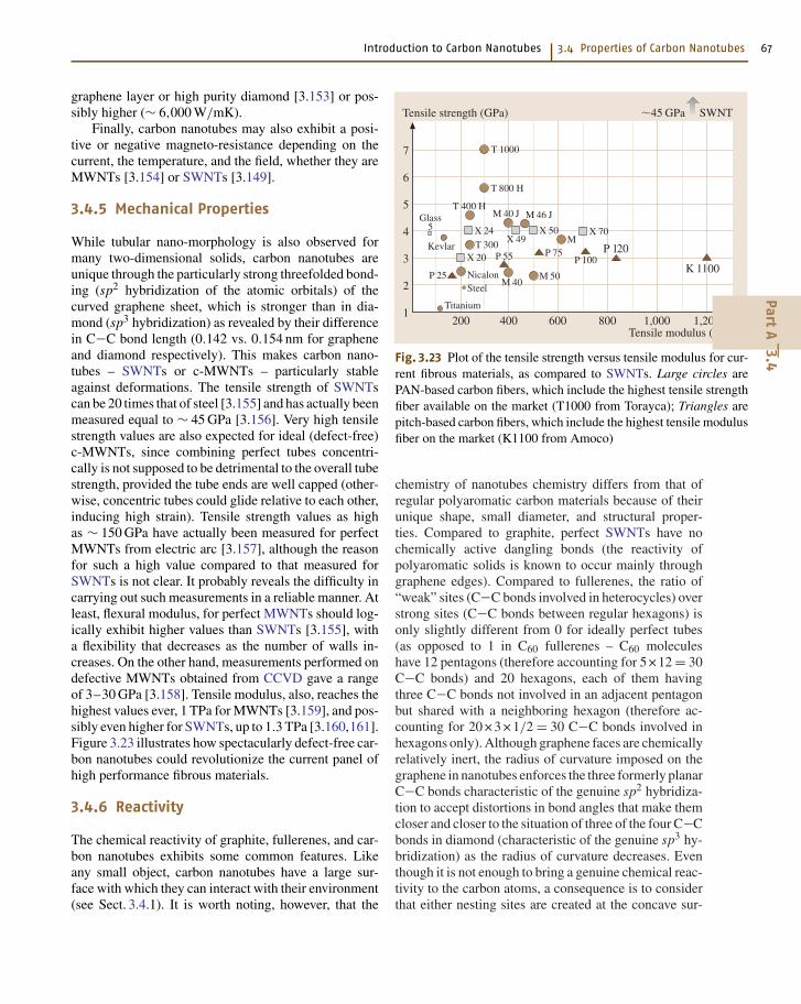
Introduction to Carbon Nanotubes 3.4 Properties of Carbon Nanotubes 67
graphene layer or high purity diamond [3.153] or pos-sibly higher (∼ 6,000 W/mK).
Finally, carbon nanotubes may also exhibit a posi-tive or negative magneto-resistance depending on thecurrent, the temperature, and the field, whether they areMWNTs [3.154] or SWNTs [3.149].
3.4.5 Mechanical Properties
While tubular nano-morphology is also observed formany two-dimensional solids, carbon nanotubes areunique through the particularly strong threefolded bond-ing (sp2 hybridization of the atomic orbitals) of thecurved graphene sheet, which is stronger than in dia-mond (sp3 hybridization) as revealed by their differencein C−C bond length (0.142 vs. 0.154 nm for grapheneand diamond respectively). This makes carbon nano-tubes – SWNTs or c-MWNTs – particularly stableagainst deformations. The tensile strength of SWNTscan be 20 times that of steel [3.155] and has actually beenmeasured equal to ∼ 45 GPa [3.156]. Very high tensilestrength values are also expected for ideal (defect-free)c-MWNTs, since combining perfect tubes concentri-cally is not supposed to be detrimental to the overall tubestrength, provided the tube ends are well capped (other-wise, concentric tubes could glide relative to each other,inducing high strain). Tensile strength values as highas ∼ 150 GPa have actually been measured for perfectMWNTs from electric arc [3.157], although the reasonfor such a high value compared to that measured forSWNTs is not clear. It probably reveals the difficulty incarrying out such measurements in a reliable manner. Atleast, flexural modulus, for perfect MWNTs should log-ically exhibit higher values than SWNTs [3.155], witha flexibility that decreases as the number of walls in-creases. On the other hand, measurements performed ondefective MWNTs obtained from CCVD gave a rangeof 3–30 GPa [3.158]. Tensile modulus, also, reaches thehighest values ever, 1 TPa for MWNTs [3.159], and pos-sibly even higher for SWNTs, up to 1.3 TPa [3.160,161].Figure 3.23 illustrates how spectacularly defect-free car-bon nanotubes could revolutionize the current panel ofhigh performance fibrous materials.
3.4.6 Reactivity
The chemical reactivity of graphite, fullerenes, and car-bon nanotubes exhibits some common features. Likeany small object, carbon nanotubes have a large sur-face with which they can interact with their environment(see Sect. 3.4.1). It is worth noting, however, that the
Tensile strength (GPa)
Tensile modulus (GPa)200
7
6
5
4
3
2
1400 600 800 1,000 1,200
T 1000
T 800 H
T 400 HGlass
5
Titanium
SteelNicalon
Kevlar
X 24
T 300X 20
P 25M 40
P 55
X 49
M 40 J M 46 J
X 50
P 75
M 50
MX 70
P 100P 120
K 1100
SWNT45 GPa
Fig. 3.23 Plot of the tensile strength versus tensile modulus for cur-rent fibrous materials, as compared to SWNTs. Large circles arePAN-based carbon fibers, which include the highest tensile strengthfiber available on the market (T1000 from Torayca); Triangles arepitch-based carbon fibers, which include the highest tensile modulusfiber on the market (K1100 from Amoco)
chemistry of nanotubes chemistry differs from that ofregular polyaromatic carbon materials because of theirunique shape, small diameter, and structural proper-ties. Compared to graphite, perfect SWNTs have nochemically active dangling bonds (the reactivity ofpolyaromatic solids is known to occur mainly throughgraphene edges). Compared to fullerenes, the ratio of“weak” sites (C−C bonds involved in heterocycles) overstrong sites (C−C bonds between regular hexagons) isonly slightly different from 0 for ideally perfect tubes(as opposed to 1 in C60 fullerenes – C60 moleculeshave 12 pentagons (therefore accounting for 5 × 12 = 30C−C bonds) and 20 hexagons, each of them havingthree C−C bonds not involved in an adjacent pentagonbut shared with a neighboring hexagon (therefore ac-counting for 20 × 3 × 1/2 = 30 C−C bonds involved inhexagons only). Although graphene faces are chemicallyrelatively inert, the radius of curvature imposed on thegraphene in nanotubes enforces the three formerly planarC−C bonds characteristic of the genuine sp2 hybridiza-tion to accept distortions in bond angles that make themcloser and closer to the situation of three of the four C−Cbonds in diamond (characteristic of the genuine sp3 hy-bridization) as the radius of curvature decreases. Eventhough it is not enough to bring a genuine chemical reac-tivity to the carbon atoms, a consequence is to considerthat either nesting sites are created at the concave sur-
PartA
3.4
68 Part A Nanostructures, Micro/Nanofabrication, and Micro/Nanodevices
face, or strong physisorption sites are created above eachcarbon atom of the convex surface, both with a bond-ing efficiency that increases as the nanotube diameterdecreases.
As already pointed out in Sect. 3.1, the chemicalreactivity of SWNTs (and c-MNWTs) is supposed tocome mainly from the caps, since they contain sixpentagons each, as opposed to the tube body, whichsupposedly contains hexagons only. Indeed, oxidizingtreatments applied to carbon nanotubes (air oxidation,wet-chemistry oxidation) are known to open the nano-tube tips rather selectively [3.162]. But the ability ofSWNTs to be opened by oxidation methods then filledwith foreign molecules such as fullerenes (see Sect. 3.5)reveals the occurrence of side defects [3.14], whose iden-tification and occurrence were discussed then proposedto be an average of one Stone–Wales defect every 5 nmalong the tube length, involving an amount of about
2% of the carbon atoms for the example of a reg-ular (10,10) SWNT [3.163] – a Stone–Wales defectis made of four adjacent heterocycles, two pentagonsand two heptagons, displayed by pairs in opposition.Such a defect actually allows localized double bondsto be formed between the carbon atoms involved in thedefect (instead of the electrons participating to the de-localized electron cloud above the graphene as usual,enhancing the chemical reactivity, e.g. toward chloro-carbenes [3.163]). This means that the overall chemicalreactivity of carbon nanotubesshould strongly dependon the way they are synthesized. For example, SWNTsprepared by the arc-discharge method are supposed tocontain fewer structural defects compared to CCVD-synthesized SWNTs, which have a higher chemicalreactivity. Of course, the reactivity of h-MWNT-typenanotubes is intrinsically higher, due to the occurrenceof accessible graphene edges at the nanotube surface.
3.5 Carbon Nanotube-Based Nano-Objects
3.5.1 Hetero-Nanotubes
Hetero-nanotubes are defined here as carbon nanotubeswhose carbon atoms, part or all of them, are substi-tuted with another element while the overall honeycomblattice-based graphene structure is maintained. Elementsinvolved are, therefore, boron and/or nitrogen. Benefitscan be new behaviors (e.g., BN nanotubes are electricalinsulators), improved properties (e.g., regarding the re-sistance to oxidation), or better control of the properties.One current challenge is actually to control the process-ing so that the desired SWNT structure is selectivelysynthesized (metallic or semiconductor). In this regard,it was demonstrated that substituting some C atoms byN or B atoms lead to SWNTs whose electrical behavioris systematically metallic [3.164, 165].
Some examples of hetero-nanotubes, though mainlyMWNTs, are found in literature, whose hetero-atominvolved is generally nitrogen due to the ease of in-troducing some gaseous or solid nitrogen and/or boroncontaining species (e.g., N2, NH3, BN, HfB2) in existingMWNT synthesis devices [3.164, 166] until completesubstitution of carbon [3.167, 168]. An amazing re-sult of such attempts to synthesize hetero-MWNTs wasthe subsequent formation of “multilayered” c-MWNTs,i. e. MWNTs whose constituting coaxial tubes werealternatively made of carbon graphenes and boronnitride graphenes [3.169]. On the other hand, exam-
ples of hetero-SWNTs are few. But the synthesis ofB- or N-containing SWNTs has been recently re-ported [3.165, 170].
3.5.2 Hybrid Carbon Nanotubes
Hybrid carbon nanotubes are here defined as carbonnanotubes, SWNTs or MWNTs, whose inner cav-ity has been filled, partially or entirely, by foreignatoms, molecules, compounds, or crystals. Such hy-brids are thereby noted as X@SWNT (or X@MWNT,if appropriate, where X is the atom, molecule, etc.involved) [3.171].
MotivationWhy filling carbon nanotubes? The very small inner cav-ity of nanotubes is an amazing tool to prepare and studythe properties of confined nanostructures of any nature,such as salts, metals, oxides, gases, or even discretemolecules like C60, for example. Because of the almostone-dimensional structure of carbon nanotubes (specif-ically considering SWNTs), different physical and/orchemical properties can be expected for the encapsulatedforeign materials or possibly for the overall hybrid ma-terials. Indeed, when the volume available inside a car-bon nanotube is small enough, the foreign material canbe made mainly of “surface atoms” of reduced coordi-nence. The overall former motivation was then to tenta-
PartA
3.5
Introduction to Carbon Nanotubes 3.5 Carbon Nanotube-Based Nano-Objects 69
tively form metal nanowires likely to be interesting forelectronic applications (quantum wires). Metals were thepreferred fillers, and nanotubes were mostly consideredmerely as nano-molds, likely to be removed afterward.But it is likely that the removal of the SWNT “container”to liberate the confined one-dimensional structure maydestroy or at least transform it because of the stabilizingeffect brought by the interactions with the nanotube wall.
Filling nanotubes while they grow (in situ filling)was one of the pioneering methods. In most cases,however, the filling step is separated from the step ofsynthesis of the nanotubes. Three methods can thenbe distinguished: (a) wet chemistry procedures, andphysical procedures, involving (b) capillarity filling bya molten material or (c) filling by a sublimated material.
Generally speaking, the estimation of the filling rateis problematic and most of the time is taken merelyfrom the TEM observation, without any statistics on thenumber of tubes observed. Moreover, as far as SWNTsare concerned, the fact that the nanotubes are gatheredinto bundles makes difficult the observation of the exactnumber of filled tubes, as well as the estimation of thefilled length for each tube.
Filling carbon nanotubes with materials that couldnot have been introduced directly is also possible. Thiscan be accomplished by first filling the nanotubes withan appropriate precursor (i. e., able to sublime, or melt,or solubilize) that will later be transformed by chemicalreaction or by a physical interaction such as electronbeam irradiation, for example [3.172]. In the case ofsecondary chemical transformation, the reduction by H2is the most frequently used to obtain nanotubes filledwith metals [3.173]. Sulfides can be obtained as well byusing H2S as reducing agent [3.173].
Because the inner diameter of SWNTs is generallysmaller than that of MWNTs, it is more difficult to fillthem, and the driving forces involved in the phenomenaare not yet totally understood (see the review paper by[3.163]). Consequently, more than one hundred articlesdealing with filled MWNTs were already published bythe time this chapter was written. We, therefore, didnot attempt to review all the works. We chose to citethe pioneering works, then to focus on the more recentworks dealing with the more challenging topic of fillingSWNTs.
In Situ Filling MethodMost of the first hybrid carbon nanotubes ever syn-thesized were directly obtained in the course of theirprocessing. This concerns only MWNTs, prepared bythe arc-discharge method in its early hours, for which the
filling materials were easily introduced in the system bydrilling a central hole in the anode and filling it with theheteroelements. First attempts were all reported the sameyear [3.174–178], with elements such as Pb, Bi, YC2,TiC, etc. Later on, Loiseau et al. [3.179] showed thatMWNTs could also be filled to several µm in length byelements such as Se, Sb, S, and Ge, but only as nanopar-ticles with elements such as Bi, B, Al and Te. Sulfur wassuggested to play an important role during the in situ for-mation of filled MWNTs by arc-discharge [3.180]. Thistechnique is no longer the preferred one because of thedifficulty in controling the filling ratio and yield and inachieving mass production.
Wet Chemistry Filling MethodThe wet chemistry method requires the opening of thenanotubes tips by chemical oxidation prior to the fill-ing step. This is generally obtained by refluxing thenanotubes in diluted nitric acid [3.181–183], althoughother oxidizing liquid media may work as well, e.g.[HCl+CrO3] [3.184] or chlorocarbenes formed fromthe photolytic dissociation of CHCl3 [3.163] as a rare ex-ample of a nonacidic liquid route for opening SWNTs. Ifa dissolved form (salt, oxide, etc.) of the desired metal ismeanwhile introduced during the opening step, some ofit will get inside the nanotubes. An annealing treatment(after washing and drying of the treated nanotubes) maythen lead to the oxide or to the metal, depending on theannealing atmosphere [3.162]. Although the wet chem-istry method looked promising because a wide variety ofmaterials can be introduced within nanotubes this way,and because it operates at temperature not much differ-ent from room temperature, attention has to be paid tothe oxidation method that has to be carried out as the firststeps. The damages brought to the nanotubes by severetreatments (e.g., nitric acid) make them improper foruse with SWNTs. Moreover, the filling yield is not veryimportant, as a probable consequence of the presenceof the solvent molecules that also enter the tube cavity,and the subsequent filled lengths rarely exceed 100 nm.Recent results have been obtained, however, using wetchemistry filling by Mittal et al. [3.184] who have filledSWNTs ropes by CrO3 with an average yield of ∼ 20%.
Molten State Filling MethodThe physical method involving a liquid (molten) phaseis more restrictive, first, because some materials maystart decomposing when they melt, and second becausethe melting point has to be compatible with the nano-tubes, i. e. thermal treatment temperature should remainbelow the temperature of transformation or damaging
PartA
3.5
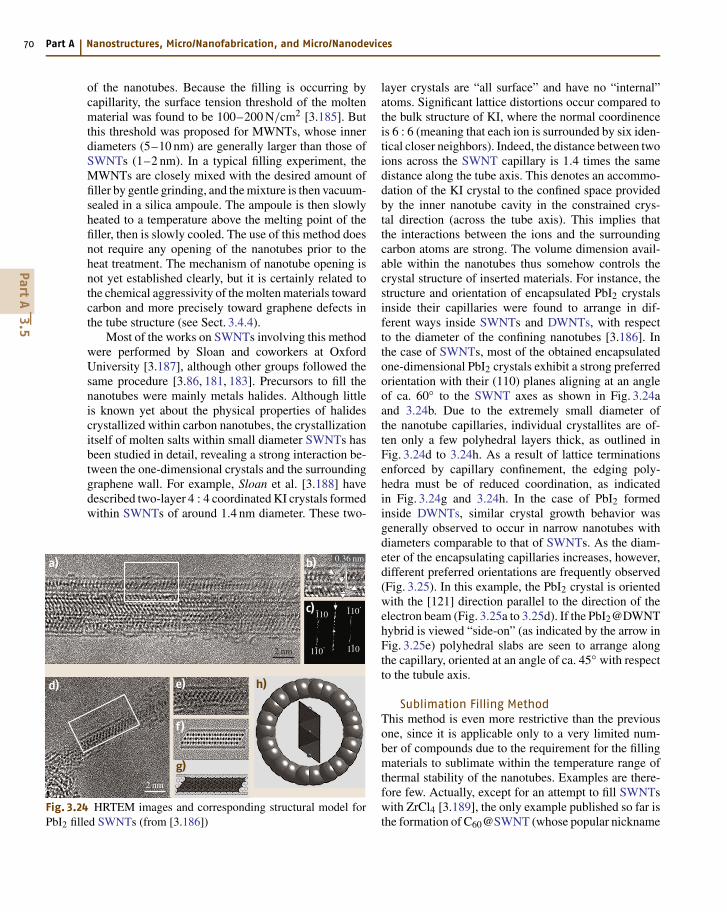
70 Part A Nanostructures, Micro/Nanofabrication, and Micro/Nanodevices
of the nanotubes. Because the filling is occurring bycapillarity, the surface tension threshold of the moltenmaterial was found to be 100–200 N/cm2 [3.185]. Butthis threshold was proposed for MWNTs, whose innerdiameters (5–10 nm) are generally larger than those ofSWNTs (1–2 nm). In a typical filling experiment, theMWNTs are closely mixed with the desired amount offiller by gentle grinding, and the mixture is then vacuum-sealed in a silica ampoule. The ampoule is then slowlyheated to a temperature above the melting point of thefiller, then is slowly cooled. The use of this method doesnot require any opening of the nanotubes prior to theheat treatment. The mechanism of nanotube opening isnot yet established clearly, but it is certainly related tothe chemical aggressivity of the molten materials towardcarbon and more precisely toward graphene defects inthe tube structure (see Sect. 3.4.4).
Most of the works on SWNTs involving this methodwere performed by Sloan and coworkers at OxfordUniversity [3.187], although other groups followed thesame procedure [3.86, 181, 183]. Precursors to fill thenanotubes were mainly metals halides. Although littleis known yet about the physical properties of halidescrystallized within carbon nanotubes, the crystallizationitself of molten salts within small diameter SWNTs hasbeen studied in detail, revealing a strong interaction be-tween the one-dimensional crystals and the surroundinggraphene wall. For example, Sloan et al. [3.188] havedescribed two-layer 4 : 4 coordinated KI crystals formedwithin SWNTs of around 1.4 nm diameter. These two-
a)
d) e)
f)
g)
h)
b)
c) -110
0.36 nm
-110.
1-101-10.
2 nm
2 nm
Fig. 3.24 HRTEM images and corresponding structural model forPbI2 filled SWNTs (from [3.186])
layer crystals are “all surface” and have no “internal”atoms. Significant lattice distortions occur compared tothe bulk structure of KI, where the normal coordinenceis 6 : 6 (meaning that each ion is surrounded by six iden-tical closer neighbors). Indeed, the distance between twoions across the SWNT capillary is 1.4 times the samedistance along the tube axis. This denotes an accommo-dation of the KI crystal to the confined space providedby the inner nanotube cavity in the constrained crys-tal direction (across the tube axis). This implies thatthe interactions between the ions and the surroundingcarbon atoms are strong. The volume dimension avail-able within the nanotubes thus somehow controls thecrystal structure of inserted materials. For instance, thestructure and orientation of encapsulated PbI2 crystalsinside their capillaries were found to arrange in dif-ferent ways inside SWNTs and DWNTs, with respectto the diameter of the confining nanotubes [3.186]. Inthe case of SWNTs, most of the obtained encapsulatedone-dimensional PbI2 crystals exhibit a strong preferredorientation with their (110) planes aligning at an angleof ca. 60 to the SWNT axes as shown in Fig. 3.24aand 3.24b. Due to the extremely small diameter ofthe nanotube capillaries, individual crystallites are of-ten only a few polyhedral layers thick, as outlined inFig. 3.24d to 3.24h. As a result of lattice terminationsenforced by capillary confinement, the edging poly-hedra must be of reduced coordination, as indicatedin Fig. 3.24g and 3.24h. In the case of PbI2 formedinside DWNTs, similar crystal growth behavior wasgenerally observed to occur in narrow nanotubes withdiameters comparable to that of SWNTs. As the diam-eter of the encapsulating capillaries increases, however,different preferred orientations are frequently observed(Fig. 3.25). In this example, the PbI2 crystal is orientedwith the [121] direction parallel to the direction of theelectron beam (Fig. 3.25a to 3.25d). If the PbI2@DWNThybrid is viewed “side-on” (as indicated by the arrow inFig. 3.25e) polyhedral slabs are seen to arrange alongthe capillary, oriented at an angle of ca. 45 with respectto the tubule axis.
Sublimation Filling MethodThis method is even more restrictive than the previousone, since it is applicable only to a very limited num-ber of compounds due to the requirement for the fillingmaterials to sublimate within the temperature range ofthermal stability of the nanotubes. Examples are there-fore few. Actually, except for an attempt to fill SWNTswith ZrCl4 [3.189], the only example published so far isthe formation of C60@SWNT (whose popular nickname
PartA
3.5
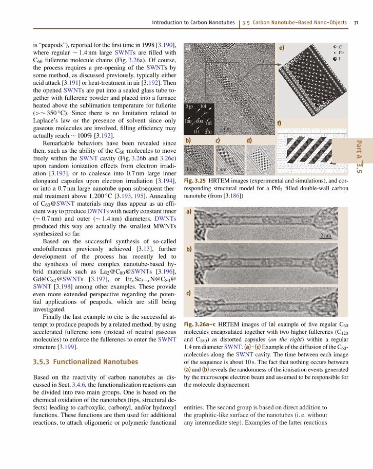
Introduction to Carbon Nanotubes 3.5 Carbon Nanotube-Based Nano-Objects 71
is “peapods”), reported for the first time in 1998 [3.190],where regular ∼ 1.4 nm large SWNTs are filled withC60 fullerene molecule chains (Fig. 3.26a). Of course,the process requires a pre-opening of the SWNTs bysome method, as discussed previously, typically eitheracid attack [3.191] or heat-treatment in air [3.192]. Thenthe opened SWNTs are put into a sealed glass tube to-gether with fullerene powder and placed into a furnaceheated above the sublimation temperature for fullerite(>∼ 350 C). Since there is no limitation related toLaplace’s law or the presence of solvent since onlygaseous molecules are involved, filling efficiency mayactually reach ∼ 100% [3.192].
Remarkable behaviors have been revealed sincethen, such as the ability of the C60 molecules to movefreely within the SWNT cavity (Fig. 3.26b and 3.26c)upon random ionization effects from electron irradi-ation [3.193], or to coalesce into 0.7 nm large innerelongated capsules upon electron irradiation [3.194],or into a 0.7 nm large nanotube upon subsequent ther-mal treatment above 1,200 C [3.193, 195]. Annealingof C60@SWNT materials may thus appear as an effi-cient way to produce DWNTs with nearly constant inner(∼ 0.7 nm) and outer (∼ 1.4 nm) diameters. DWNTsproduced this way are actually the smallest MWNTssynthesized so far.
Based on the successful synthesis of so-calledendofullerenes previously achieved [3.13], furtherdevelopment of the process has recently led tothe synthesis of more complex nanotube-based hy-brid materials such as La2@C80@SWNTs [3.196],Gd@C82@SWNTs [3.197], or ErxSc3−xN@C80@SWNT [3.198] among other examples. These provideeven more extended perspective regarding the poten-tial applications of peapods, which are still beinginvestigated.
Finally the last example to cite is the successful at-tempt to produce peapods by a related method, by usingaccelerated fullerene ions (instead of neutral gaseousmolecules) to enforce the fullerenes to enter the SWNTstructure [3.199].
3.5.3 Functionalized Nanotubes
Based on the reactivity of carbon nanotubes as dis-cussed in Sect. 3.4.6, the functionalization reactions canbe divided into two main groups. One is based on thechemical oxidation of the nanotubes (tips, structural de-fects) leading to carboxylic, carbonyl, and/or hydroxylfunctions. These functions are then used for additionalreactions, to attach oligomeric or polymeric functional
2 nm
1 nm 1 nm
-100
1-11 2-10
10-1000
-210-10-1
CPbI
a) e)
b) c) d)
f)
Fig. 3.25 HRTEM images (experimental and simulations), and cor-responding structural model for a PbI2 filled double-wall carbonnanotube (from [3.186])
2 nm
a)
b)
c)
Fig. 3.26a–c HRTEM images of (a) example of five regular C60
molecules encapsulated together with two higher fullerenes (C120
and C180) as distorted capsules (on the right) within a regular1.4 nm diameter SWNT. (a)–(c) Example of the diffusion of the C60-molecules along the SWNT cavity. The time between each imageof the sequence is about 10 s. The fact that nothing occurs between(a) and (b) reveals the randomness of the ionisation events generatedby the microscope electron beam and assumed to be responsible forthe molecule displacement
entities. The second group is based on direct addition tothe graphitic-like surface of the nanotubes (i. e. withoutany intermediate step). Examples of the latter reactions
PartA
3.5
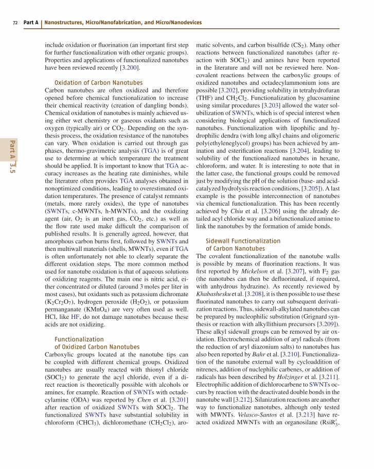
72 Part A Nanostructures, Micro/Nanofabrication, and Micro/Nanodevices
include oxidation or fluorination (an important first stepfor further functionalization with other organic groups).Properties and applications of functionalized nanotubeshave been reviewed recently [3.200].
Oxidation of Carbon NanotubesCarbon nanotubes are often oxidized and thereforeopened before chemical functionalization to increasetheir chemical reactivity (creation of dangling bonds).Chemical oxidation of nanotubes is mainly achieved us-ing either wet chemistry or gaseous oxidants such asoxygen (typically air) or CO2. Depending on the syn-thesis process, the oxidation resistance of the nanotubescan vary. When oxidation is carried out through gasphases, thermo-gravimetric analysis (TGA) is of greatuse to determine at which temperature the treatmentshould be applied. It is important to know that TGA ac-curacy increases as the heating rate diminishes, whilethe literature often provides TGA analyses obtained innonoptimized conditions, leading to overestimated oxi-dation temperatures. The presence of catalyst remnants(metals, more rarely oxides), the type of nanotubes(SWNTs, c-MWNTs, h-MWNTs), and the oxidizingagent (air, O2 is an inert gas, CO2, etc.) as well asthe flow rate used make difficult the comparison ofpublished results. It is generally agreed, however, thatamorphous carbon burns first, followed by SWNTs andthen multiwall materials (shells, MWNTs), even if TGAis often unfortunately not able to clearly separate thedifferent oxidation steps. The more common methodused for nanotube oxidation is that of aqueous solutionsof oxidizing reagents. The main one is nitric acid, ei-ther concentrated or diluted (around 3 moles per liter inmost cases), but oxidants such as potassium dichromate(K2Cr2O7), hydrogen peroxide (H2O2), or potassiumpermanganate (KMnO4) are very often used as well.HCl, like HF, do not damage nanotubes because theseacids are not oxidizing.
Functionalizationof Oxidized Carbon Nanotubes
Carboxylic groups located at the nanotube tips canbe coupled with different chemical groups. Oxidizednanotubes are usually reacted with thionyl chloride(SOCl2) to generate the acyl chloride, even if a di-rect reaction is theoretically possible with alcohols oramines, for example. Reaction of SWNTs with octade-cylamine (ODA) was reported by Chen et al. [3.201]after reaction of oxidized SWNTs with SOCl2. Thefunctionalized SWNTs have substantial solubility inchloroform (CHCl3), dichloromethane (CH2Cl2), aro-
matic solvents, and carbon bisulfide (CS2). Many otherreactions between functionalized nanotubes (after re-action with SOCl2) and amines have been reportedin the literature and will not be reviewed here. Non-covalent reactions between the carboxylic groups ofoxidized nanotubes and octadecylammonium ions arepossible [3.202], providing solubility in tetrahydrofuran(THF) and CH2Cl2. Functionalization by glucosamineusing similar procedures [3.203] allowed the water sol-ubilization of SWNTs, which is of special interest whenconsidering biological applications of functionalizednanotubes. Functionalization with lipophilic and hy-drophilic dendra (with long alkyl chains and oligomericpoly(ethyleneglycol) groups) has been achieved by am-ination and esterification reactions [3.204], leading tosolubility of the functionalized nanotubes in hexane,chloroform, and water. It is interesting to note that inthe latter case, the functional groups could be removedjust by modifying the pH of the solution (base- and acid-catalyzed hydrolysis reaction conditions, [3.205]). A lastexample is the possible interconnection of nanotubesvia chemical functionalization. This has been recentlyachieved by Chiu et al. [3.206] using the already de-tailed acyl chloride way and a bifunctionalized amine tolink the nanotubes by the formation of amide bonds.
Sidewall Functionalizationof Carbon Nanotubes
The covalent functionalization of the nanotube wallsis possible by means of fluorination reactions. It wasfirst reported by Mickelson et al. [3.207], with F2 gas(the nanotubes can then be defluorinated, if required,with anhydrous hydrazine). As recently reviewed byKhabashesku et al. [3.208], it is then possible to use thesefluorinated nanotubes to carry out subsequent derivati-zation reactions. Thus, sidewall-alkylated nanotubes canbe prepared by nucleophilic substitution (Grignard syn-thesis or reaction with alkyllithium precursors [3.209]).These alkyl sidewall groups can be removed by air ox-idation. Electrochemical addition of aryl radicals (fromthe reduction of aryl diazonium salts) to nanotubes hasalso been reported by Bahr et al. [3.210]. Functionaliza-tion of the nanotube external wall by cycloaddition ofnitrenes, addition of nuclephilic carbenes, or addition ofradicals has been described by Holzinger et al. [3.211].Electrophilic addition of dichlorocarbene to SWNTs oc-curs by reaction with the deactivated double bonds in thenanotube wall [3.212]. Silanization reactions are anotherway to functionalize nanotubes, although only testedwith MWNTs. Velasco-Santos et al. [3.213] have re-acted oxidized MWNTs with an organosilane (RsiR′
3,
PartA
3.5
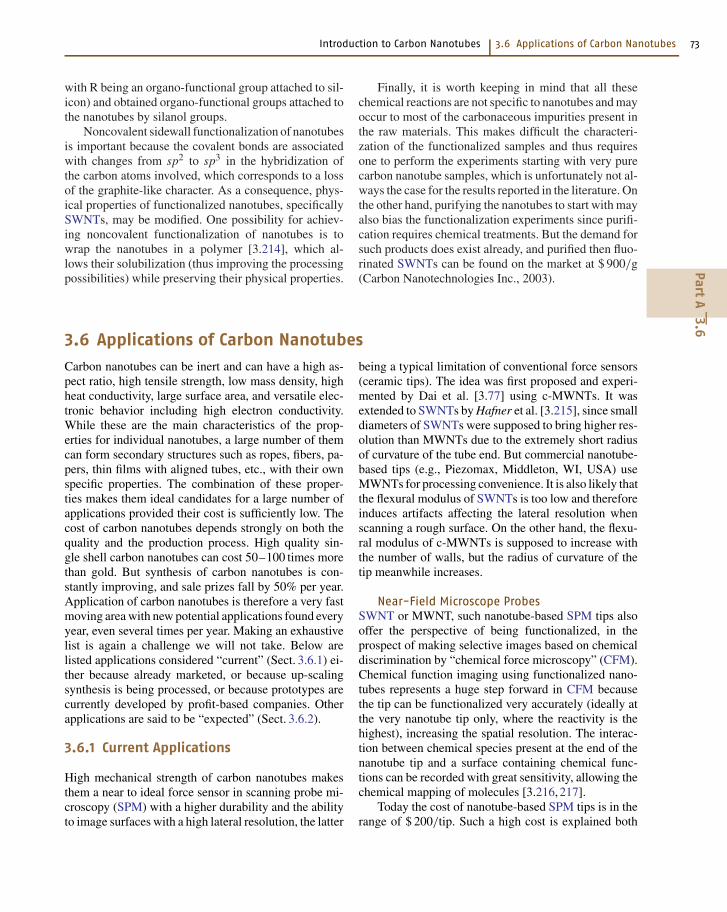
Introduction to Carbon Nanotubes 3.6 Applications of Carbon Nanotubes 73
with R being an organo-functional group attached to sil-icon) and obtained organo-functional groups attached tothe nanotubes by silanol groups.
Noncovalent sidewall functionalization of nanotubesis important because the covalent bonds are associatedwith changes from sp2 to sp3 in the hybridization ofthe carbon atoms involved, which corresponds to a lossof the graphite-like character. As a consequence, phys-ical properties of functionalized nanotubes, specificallySWNTs, may be modified. One possibility for achiev-ing noncovalent functionalization of nanotubes is towrap the nanotubes in a polymer [3.214], which al-lows their solubilization (thus improving the processingpossibilities) while preserving their physical properties.
Finally, it is worth keeping in mind that all thesechemical reactions are not specific to nanotubes and mayoccur to most of the carbonaceous impurities present inthe raw materials. This makes difficult the characteri-zation of the functionalized samples and thus requiresone to perform the experiments starting with very purecarbon nanotube samples, which is unfortunately not al-ways the case for the results reported in the literature. Onthe other hand, purifying the nanotubes to start with mayalso bias the functionalization experiments since purifi-cation requires chemical treatments. But the demand forsuch products does exist already, and purified then fluo-rinated SWNTs can be found on the market at $ 900/g(Carbon Nanotechnologies Inc., 2003).
3.6 Applications of Carbon Nanotubes
Carbon nanotubes can be inert and can have a high as-pect ratio, high tensile strength, low mass density, highheat conductivity, large surface area, and versatile elec-tronic behavior including high electron conductivity.While these are the main characteristics of the prop-erties for individual nanotubes, a large number of themcan form secondary structures such as ropes, fibers, pa-pers, thin films with aligned tubes, etc., with their ownspecific properties. The combination of these proper-ties makes them ideal candidates for a large number ofapplications provided their cost is sufficiently low. Thecost of carbon nanotubes depends strongly on both thequality and the production process. High quality sin-gle shell carbon nanotubes can cost 50–100 times morethan gold. But synthesis of carbon nanotubes is con-stantly improving, and sale prizes fall by 50% per year.Application of carbon nanotubes is therefore a very fastmoving area with new potential applications found everyyear, even several times per year. Making an exhaustivelist is again a challenge we will not take. Below arelisted applications considered “current” (Sect. 3.6.1) ei-ther because already marketed, or because up-scalingsynthesis is being processed, or because prototypes arecurrently developed by profit-based companies. Otherapplications are said to be “expected” (Sect. 3.6.2).
3.6.1 Current Applications
High mechanical strength of carbon nanotubes makesthem a near to ideal force sensor in scanning probe mi-croscopy (SPM) with a higher durability and the abilityto image surfaces with a high lateral resolution, the latter
being a typical limitation of conventional force sensors(ceramic tips). The idea was first proposed and experi-mented by Dai et al. [3.77] using c-MWNTs. It wasextended to SWNTs by Hafner et al. [3.215], since smalldiameters of SWNTs were supposed to bring higher res-olution than MWNTs due to the extremely short radiusof curvature of the tube end. But commercial nanotube-based tips (e.g., Piezomax, Middleton, WI, USA) useMWNTs for processing convenience. It is also likely thatthe flexural modulus of SWNTs is too low and thereforeinduces artifacts affecting the lateral resolution whenscanning a rough surface. On the other hand, the flexu-ral modulus of c-MWNTs is supposed to increase withthe number of walls, but the radius of curvature of thetip meanwhile increases.
Near-Field Microscope ProbesSWNT or MWNT, such nanotube-based SPM tips alsooffer the perspective of being functionalized, in theprospect of making selective images based on chemicaldiscrimination by “chemical force microscopy” (CFM).Chemical function imaging using functionalized nano-tubes represents a huge step forward in CFM becausethe tip can be functionalized very accurately (ideally atthe very nanotube tip only, where the reactivity is thehighest), increasing the spatial resolution. The interac-tion between chemical species present at the end of thenanotube tip and a surface containing chemical func-tions can be recorded with great sensitivity, allowing thechemical mapping of molecules [3.216, 217].
Today the cost of nanotube-based SPM tips is in therange of $ 200/tip. Such a high cost is explained both
PartA
3.6
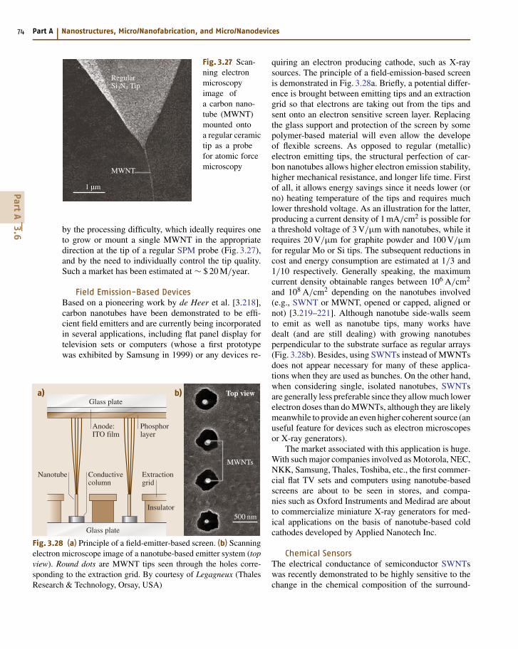
74 Part A Nanostructures, Micro/Nanofabrication, and Micro/Nanodevices
1 µm
RegularSi3N4 Tip
MWNT
Fig. 3.27 Scan-ning electronmicroscopyimage ofa carbon nano-tube (MWNT)mounted ontoa regular ceramictip as a probefor atomic forcemicroscopy
by the processing difficulty, which ideally requires oneto grow or mount a single MWNT in the appropriatedirection at the tip of a regular SPM probe (Fig. 3.27),and by the need to individually control the tip quality.Such a market has been estimated at ∼ $ 20 M/year.
Field Emission-Based DevicesBased on a pioneering work by de Heer et al. [3.218],carbon nanotubes have been demonstrated to be effi-cient field emitters and are currently being incorporatedin several applications, including flat panel display fortelevision sets or computers (whose a first prototypewas exhibited by Samsung in 1999) or any devices re-
a)
Anode:ITO film
Phosphorlayer
Extractiongrid
Insulator
Nanotube Conductivecolumn
Glass plate
Glass plate
MWNTs
500 nm
b) Top view
Fig. 3.28 (a) Principle of a field-emitter-based screen. (b) Scanningelectron microscope image of a nanotube-based emitter system (topview). Round dots are MWNT tips seen through the holes corre-sponding to the extraction grid. By courtesy of Legagneux (ThalesResearch & Technology, Orsay, USA)
quiring an electron producing cathode, such as X-raysources. The principle of a field-emission-based screenis demonstrated in Fig. 3.28a. Briefly, a potential differ-ence is brought between emitting tips and an extractiongrid so that electrons are taking out from the tips andsent onto an electron sensitive screen layer. Replacingthe glass support and protection of the screen by somepolymer-based material will even allow the developeof flexible screens. As opposed to regular (metallic)electron emitting tips, the structural perfection of car-bon nanotubes allows higher electron emission stability,higher mechanical resistance, and longer life time. Firstof all, it allows energy savings since it needs lower (orno) heating temperature of the tips and requires muchlower threshold voltage. As an illustration for the latter,producing a current density of 1 mA/cm2 is possible fora threshold voltage of 3 V/µm with nanotubes, while itrequires 20 V/µm for graphite powder and 100 V/µmfor regular Mo or Si tips. The subsequent reductions incost and energy consumption are estimated at 1/3 and1/10 respectively. Generally speaking, the maximumcurrent density obtainable ranges between 106 A/cm2
and 108 A/cm2 depending on the nanotubes involved(e.g., SWNT or MWNT, opened or capped, aligned ornot) [3.219–221]. Although nanotube side-walls seemto emit as well as nanotube tips, many works havedealt (and are still dealing) with growing nanotubesperpendicular to the substrate surface as regular arrays(Fig. 3.28b). Besides, using SWNTs instead of MWNTsdoes not appear necessary for many of these applica-tions when they are used as bunches. On the other hand,when considering single, isolated nanotubes, SWNTsare generally less preferable since they allow much lowerelectron doses than do MWNTs, although they are likelymeanwhile to provide an even higher coherent source (anuseful feature for devices such as electron microscopesor X-ray generators).
The market associated with this application is huge.With such major companies involved as Motorola, NEC,NKK, Samsung, Thales, Toshiba, etc., the first commer-cial flat TV sets and computers using nanotube-basedscreens are about to be seen in stores, and compa-nies such as Oxford Instruments and Medirad are aboutto commercialize miniature X-ray generators for med-ical applications on the basis of nanotube-based coldcathodes developed by Applied Nanotech Inc.
Chemical SensorsThe electrical conductance of semiconductor SWNTswas recently demonstrated to be highly sensitive to thechange in the chemical composition of the surround-
PartA
3.6
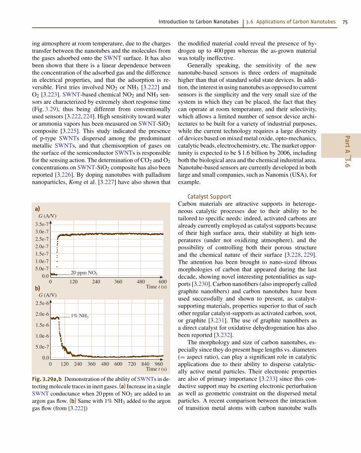
Introduction to Carbon Nanotubes 3.6 Applications of Carbon Nanotubes 75
ing atmosphere at room temperature, due to the chargestransfer between the nanotubes and the molecules fromthe gases adsorbed onto the SWNT surface. It has alsobeen shown that there is a linear dependence betweenthe concentration of the adsorbed gas and the differencein electrical properties, and that the adsorption is re-versible. First tries involved NO2 or NH3 [3.222] andO2 [3.223]. SWNT-based chemical NO2 and NH3 sen-sors are characterized by extremely short response time(Fig. 3.29), thus being different from conventionallyused sensors [3.222,224]. High sensitivity toward wateror ammonia vapors has been measured on SWNT-SiO2composite [3.225]. This study indicated the presenceof p-type SWNTs dispersed among the predominantmetallic SWNTs, and that chemisorption of gases onthe surface of the semiconductor SWNTs is responsiblefor the sensing action. The determination of CO2 and O2concentrations on SWNT-SiO2 composite has also beenreported [3.226]. By doping nanotubes with palladiumnanoparticles, Kong et al. [3.227] have also shown that
G (A/V)
Time t (s)0 600
3.5e-7
3.0e-7
2.5e-7
2.0e-7
1.5e-7
1.0e-7
5.0e-7
0.0120 240 360 480
G (A/V)
Time t (s)0 960
2.5e-6
2.0e-6
1.5e-6
1.0e-6
5.0e-7
0.0120 240 360 480 600 720 840
20 ppm NO3
1% NH3
a)
b)
Fig. 3.29a,b Demonstration of the ability of SWNTs in de-tecting molecule traces in inert gases. (a) Increase in a singleSWNT conductance when 20 ppm of NO2 are added to anargon gas flow. (b) Same with 1% NH3 added to the argongas flow (from [3.222])
the modified material could reveal the presence of hy-drogen up to 400 ppm whereas the as-grown materialwas totally ineffective.
Generally speaking, the sensitivity of the newnanotube-based sensors is three orders of magnitudehigher than that of standard solid state devices. In addi-tion, the interest in using nanotubes as opposed to currentsensors is the simplicity and the very small size of thesystem in which they can be placed, the fact that theycan operate at room temperature, and their selectivity,which allows a limited number of sensor device archi-tectures to be built for a variety of industrial purposes,while the current technology requires a large diversityof devices based on mixed metal oxide, opto-mechanics,catalytic beads, electrochemistry, etc. The market oppor-tunity is expected to be $ 1.6 billion by 2006, includingboth the biological area and the chemical industrial area.Nanotube-based sensors are currently developed in bothlarge and small companies, such as Nanomix (USA), forexample.
Catalyst SupportCarbon materials are attractive supports in heteroge-neous catalytic processes due to their ability to betailored to specific needs: indeed, activated carbons arealready currently employed as catalyst supports becauseof their high surface area, their stability at high tem-peratures (under not oxidizing atmosphere), and thepossibility of controlling both their porous structureand the chemical nature of their surface [3.228, 229].The attention has been brought to nano-sized fibrousmorphologies of carbon that appeared during the lastdecade, showing novel interesting potentialities as sup-ports [3.230]. Carbon nanofibers (also improperly calledgraphite nanofibers) and carbon nanotubes have beenused successfully and shown to present, as catalyst-supporting materials, properties superior to that of suchother regular catalyst-supports as activated carbon, soot,or graphite [3.231]. The use of graphite nanofibers asa direct catalyst for oxidative dehydrogenation has alsobeen reported [3.232].
The morphology and size of carbon nanotubes, es-pecially since they do present huge lengths vs. diameters(= aspect ratio), can play a significant role in catalyticapplications due to their ability to disperse catalytic-ally active metal particles. Their electronic propertiesare also of primary importance [3.233] since this con-ductive support may be exerting electronic perturbationas well as geometric constraint on the dispersed metalparticles. A recent comparison between the interactionof transition metal atoms with carbon nanotube walls
PartA
3.6
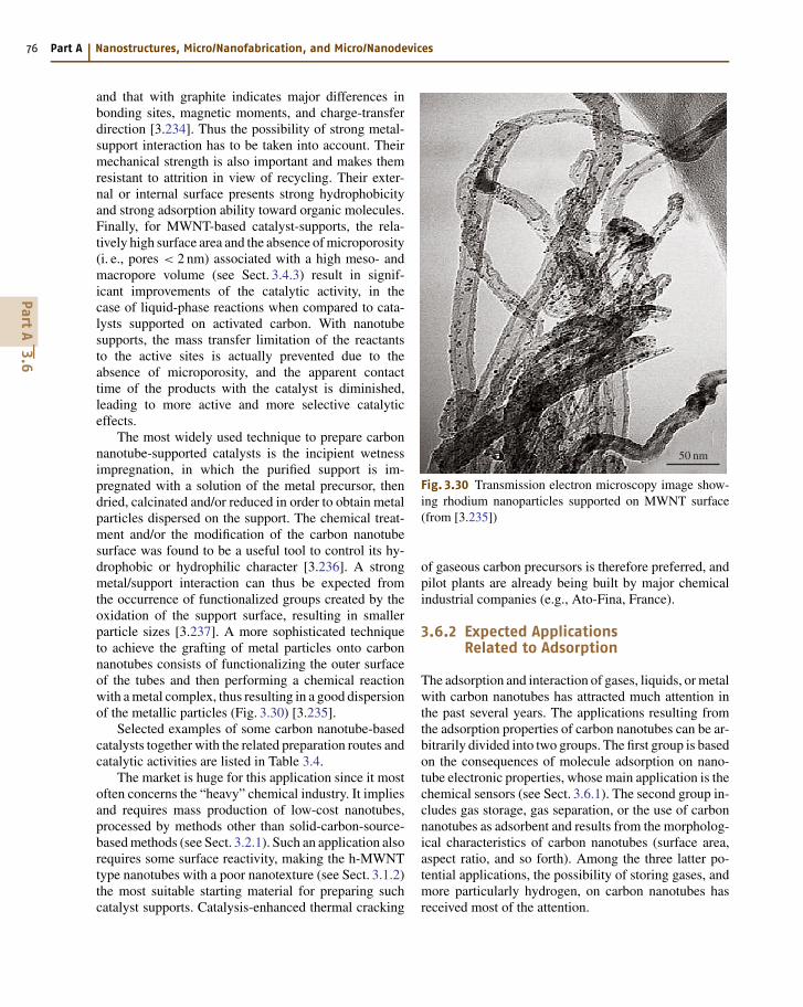
76 Part A Nanostructures, Micro/Nanofabrication, and Micro/Nanodevices
and that with graphite indicates major differences inbonding sites, magnetic moments, and charge-transferdirection [3.234]. Thus the possibility of strong metal-support interaction has to be taken into account. Theirmechanical strength is also important and makes themresistant to attrition in view of recycling. Their exter-nal or internal surface presents strong hydrophobicityand strong adsorption ability toward organic molecules.Finally, for MWNT-based catalyst-supports, the rela-tively high surface area and the absence of microporosity(i. e., pores < 2 nm) associated with a high meso- andmacropore volume (see Sect. 3.4.3) result in signif-icant improvements of the catalytic activity, in thecase of liquid-phase reactions when compared to cata-lysts supported on activated carbon. With nanotubesupports, the mass transfer limitation of the reactantsto the active sites is actually prevented due to theabsence of microporosity, and the apparent contacttime of the products with the catalyst is diminished,leading to more active and more selective catalyticeffects.
The most widely used technique to prepare carbonnanotube-supported catalysts is the incipient wetnessimpregnation, in which the purified support is im-pregnated with a solution of the metal precursor, thendried, calcinated and/or reduced in order to obtain metalparticles dispersed on the support. The chemical treat-ment and/or the modification of the carbon nanotubesurface was found to be a useful tool to control its hy-drophobic or hydrophilic character [3.236]. A strongmetal/support interaction can thus be expected fromthe occurrence of functionalized groups created by theoxidation of the support surface, resulting in smallerparticle sizes [3.237]. A more sophisticated techniqueto achieve the grafting of metal particles onto carbonnanotubes consists of functionalizing the outer surfaceof the tubes and then performing a chemical reactionwith a metal complex, thus resulting in a good dispersionof the metallic particles (Fig. 3.30) [3.235].
Selected examples of some carbon nanotube-basedcatalysts together with the related preparation routes andcatalytic activities are listed in Table 3.4.
The market is huge for this application since it mostoften concerns the “heavy” chemical industry. It impliesand requires mass production of low-cost nanotubes,processed by methods other than solid-carbon-source-based methods (see Sect. 3.2.1). Such an application alsorequires some surface reactivity, making the h-MWNTtype nanotubes with a poor nanotexture (see Sect. 3.1.2)the most suitable starting material for preparing suchcatalyst supports. Catalysis-enhanced thermal cracking
50 nm
Fig. 3.30 Transmission electron microscopy image show-ing rhodium nanoparticles supported on MWNT surface(from [3.235])
of gaseous carbon precursors is therefore preferred, andpilot plants are already being built by major chemicalindustrial companies (e.g., Ato-Fina, France).
3.6.2 Expected ApplicationsRelated to Adsorption
The adsorption and interaction of gases, liquids, or metalwith carbon nanotubes has attracted much attention inthe past several years. The applications resulting fromthe adsorption properties of carbon nanotubes can be ar-bitrarily divided into two groups. The first group is basedon the consequences of molecule adsorption on nano-tube electronic properties, whose main application is thechemical sensors (see Sect. 3.6.1). The second group in-cludes gas storage, gas separation, or the use of carbonnanotubes as adsorbent and results from the morpholog-ical characteristics of carbon nanotubes (surface area,aspect ratio, and so forth). Among the three latter po-tential applications, the possibility of storing gases, andmore particularly hydrogen, on carbon nanotubes hasreceived most of the attention.
PartA
3.6
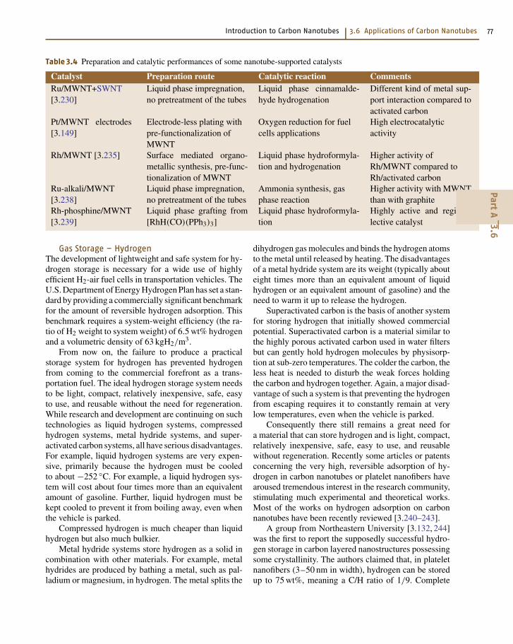
Introduction to Carbon Nanotubes 3.6 Applications of Carbon Nanotubes 77
Table 3.4 Preparation and catalytic performances of some nanotube-supported catalysts
Catalyst Preparation route Catalytic reaction CommentsRu/MWNT+SWNT[3.230]
Liquid phase impregnation,no pretreatment of the tubes
Liquid phase cinnamalde-hyde hydrogenation
Different kind of metal sup-port interaction compared toactivated carbon
Pt/MWNT electrodes[3.149]
Electrode-less plating withpre-functionalization ofMWNT
Oxygen reduction for fuelcells applications
High electrocatalyticactivity
Rh/MWNT [3.235] Surface mediated organo-metallic synthesis, pre-func-tionalization of MWNT
Liquid phase hydroformyla-tion and hydrogenation
Higher activity ofRh/MWNT compared toRh/activated carbon
Ru-alkali/MWNT[3.238]
Liquid phase impregnation,no pretreatment of the tubes
Ammonia synthesis, gasphase reaction
Higher activity with MWNTthan with graphite
Rh-phosphine/MWNT[3.239]
Liquid phase grafting from[RhH(CO)(PPh3)3]
Liquid phase hydroformyla-tion
Highly active and regiose-lective catalyst
Gas Storage – HydrogenThe development of lightweight and safe system for hy-drogen storage is necessary for a wide use of highlyefficient H2-air fuel cells in transportation vehicles. TheU.S. Department of Energy Hydrogen Plan has set a stan-dard by providing a commercially significant benchmarkfor the amount of reversible hydrogen adsorption. Thisbenchmark requires a system-weight efficiency (the ra-tio of H2 weight to system weight) of 6.5 wt% hydrogenand a volumetric density of 63 kgH2/m3.
From now on, the failure to produce a practicalstorage system for hydrogen has prevented hydrogenfrom coming to the commercial forefront as a trans-portation fuel. The ideal hydrogen storage system needsto be light, compact, relatively inexpensive, safe, easyto use, and reusable without the need for regeneration.While research and development are continuing on suchtechnologies as liquid hydrogen systems, compressedhydrogen systems, metal hydride systems, and super-activated carbon systems, all have serious disadvantages.For example, liquid hydrogen systems are very expen-sive, primarily because the hydrogen must be cooledto about −252 C. For example, a liquid hydrogen sys-tem will cost about four times more than an equivalentamount of gasoline. Further, liquid hydrogen must bekept cooled to prevent it from boiling away, even whenthe vehicle is parked.
Compressed hydrogen is much cheaper than liquidhydrogen but also much bulkier.
Metal hydride systems store hydrogen as a solid incombination with other materials. For example, metalhydrides are produced by bathing a metal, such as pal-ladium or magnesium, in hydrogen. The metal splits the
dihydrogen gas molecules and binds the hydrogen atomsto the metal until released by heating. The disadvantagesof a metal hydride system are its weight (typically abouteight times more than an equivalent amount of liquidhydrogen or an equivalent amount of gasoline) and theneed to warm it up to release the hydrogen.
Superactivated carbon is the basis of another systemfor storing hydrogen that initially showed commercialpotential. Superactivated carbon is a material similar tothe highly porous activated carbon used in water filtersbut can gently hold hydrogen molecules by physisorp-tion at sub-zero temperatures. The colder the carbon, theless heat is needed to disturb the weak forces holdingthe carbon and hydrogen together. Again, a major disad-vantage of such a system is that preventing the hydrogenfrom escaping requires it to constantly remain at verylow temperatures, even when the vehicle is parked.
Consequently there still remains a great need fora material that can store hydrogen and is light, compact,relatively inexpensive, safe, easy to use, and reusablewithout regeneration. Recently some articles or patentsconcerning the very high, reversible adsorption of hy-drogen in carbon nanotubes or platelet nanofibers havearoused tremendous interest in the research community,stimulating much experimental and theoretical works.Most of the works on hydrogen adsorption on carbonnanotubes have been recently reviewed [3.240–243].
A group from Northeastern University [3.132, 244]was the first to report the supposedly successful hydro-gen storage in carbon layered nanostructures possessingsome crystallinity. The authors claimed that, in plateletnanofibers (3–50 nm in width), hydrogen can be storedup to 75 wt%, meaning a C/H ratio of 1/9. Complete
PartA
3.6
78 Part A Nanostructures, Micro/Nanofabrication, and Micro/Nanodevices
hydrogen desorption occurs only at very high tempera-ture. The same authors have recently pointed out thedramatic role of the treatment that has to be applied tothe carbon nanofibers prior to H2 adsorption [3.244].This thermal treatment, though simple (1,000 C in aninert gas), is a critical procedure in order to removechemisorbed gases from the edge and step regions ofthe carbon structures. Failure to achieve this condi-tion results in a dramatic decrease in the hydrogenadsorption performance of the materials. In this work,the authors have performed the experiments at roomtemperature, and 100 bar of H2, hydrogen uptake be-tween 20 and 40 wt% were recorded. The authors havealso demonstrated by XRD measurements that structuralperturbation of the material was produced followinghydrogen treatment, and that it was manifested by an ex-pansion of the graphitic interplane distance (from 0.34before H2 adsorption to 0.347 after H2 uptake).
Hydrogen adsorption and desorption measurementson nanofibers similar to that used by Rodriguezet al. [3.19] were also performed by Ahn et al. [3.245].The authors have measured a hydrogen uptake of2.4 wt%. In fact, in their study, none of the graphitenanofiber material tested has indicated hydrogen stor-age abilities that exceed the values already reported foractivated carbons.
Adsorption of H2 on platelet nanofibers was com-puted by Monte Carlo simulations [3.246]. The graphenespacing was optimized to maximize the weight fractionof H2 adsorbed. Given the results of their calcula-tions, the authors concluded that no physically realisticgraphite-hydrogen potential can account for the tremen-dous adsorption ability reported by the group from PennState.
Rzepka et al. [3.247] have also used theoreticalMonte Carlo calculation to calculate the amount of phys-ically adsorbed hydrogen molecules in carbon slit poresof dimensions similar to that used by the Penn Stategroup (i. e., 0.34 nm as the interplanar distance betweengraphenes in the nanofibers). They reached the conclu-sion that no hydrogen can be adsorbed at all. Even ifthe interplanar distance is assumed to expand duringthe adsorption process, the maximum calculated adsorp-tion is 1 wt% for d = 0.7 nm. These authors concludedthat the Penn State experimental results could not beattributed to some “abnormal capillary condensation ef-fect” as initially claimed. Since then, nobody has beenable to duplicate it experimentally.
Meanwhile, hydrogen storage experiments were alsoattempted on SWNTs. The first work was reported byDillon et al. [3.248] who used temperature-programmed
desorption measurements. A major drawback of theirexperimental procedure was that they used only 1 mg ofunpurified soot containing 0.1% of SWNTs. They at-tributed the reversible hydrogen capacity of 0.01 wt%observed to the SWNTs only, therefore leading to a pre-sumable capacity of 5–10 wt% for a pure nanotubessample. TPD experiments shown H2 desorption between−170 and +100 C. Despite the weakness of the demon-stration, the paper, which was published not much beforethat of Chambers et al. [3.132], has induced a worldwideexcitement for the field.
Hydrogen adsorption measurements were also per-formed on SWNT samples of high purity [3.249]. At−193 C, 160 bar of H2 were admitted and the hydro-gen adsorption was found to exceed 8 wt%. In this case,the authors proposed that hydrogen is first adsorbed onthe outer surfaces of the crystalline material. But no dataconcerning H2 desorption are given.
In recent reports, Dresselhaus and coworkers [3.240,250] reported hydrogen storage in SWNTs (1.85 nmof average diameter) at room temperature. A hydrogenstorage capacity of 4.2 wt% was achieved reproduciblyunder 100 bar for a SWNT-containing material of about0.5 g that was previously soaked in hydrochloric acid andthen heat-treated (500 C) in vacuum. The purity of thesample was estimated from TGA and TEM observationsto be about 50 to 60%. Moreover, 78% of the adsorbedhydrogen could be released under ambient pressureat room temperature, while the release of the residualstored hydrogen required some heating at 200 C.
A valuable input to the topic was brought byHirscher et al. [3.251], who demonstrated that severalof the supposedly successful experiments regarding thestorage of H2 in SWNTs were actually misled by thehydrogen storage capacity of Ti nanoparticles originat-ing from the sonoprobe frequently used at one step oranother of the procedure, specifically when the SWNTmaterial is previously purified.
Density functional theory (DFT) was used [3.252]to estimate H2 adsorption in SWNTs. From their calcu-lations, within the regime of operating conditions whereadsorptive storage seems attractive, the storage proper-ties of H2 in a SWNT system appear to fall far shortof the DOE target. In their model, rolling graphite intoa cylindrical sheet does not significantly alter the natureof the carbon–H2 interaction, in contradiction with thelatest calculations, which indicate that the possibilitiesof physisorption increase as the radius of curvature ofSWNTs decreases [3.253].
More recently, however, Lee et al. [3.254, 255] havealso used DFT calculations to search for hydrogen ad-
PartA
3.6
Introduction to Carbon Nanotubes 3.6 Applications of Carbon Nanotubes 79
sorption sites and predict maximum storage capacity inSWNTs. They have found two chemisorption sites, atthe exterior and the interior of the tube wall. Thus theypredict a maximum hydrogen storage capacity that canexceed 14 wt% (160 kgH2/m3). The authors have alsoconsidered H2 adsorption in multiwall carbon nanotubesand have predicted lower storage capacities for the latter.
Calculations are constrained, however, by the start-ing hypotheses. While considering the same (10,10)SWNT, although calculations based on DFT predicta 14.3% storage [3.254], calculations based on a geomet-rical model predict 3.3% [3.240], and calculations basedon quantum mechanical molecular dynamics model pre-dict 0.47% [3.256].
In conclusion, neither the experimental results, ob-viously biased by some problem in the procedures, northeoretical results are yet able to demonstrate that an ef-ficient storage of H2 is achievable for carbon nanotubes,whatever the type. But the definitive failure statementcannot yet be claimed. Further efforts have to be madeto enhance H2 adsorption of these materials, in par-ticular (i) by adjusting the surface properties that canbe modified by chemical or mechanical treatments, and(ii) by adjusting the material structure (pore size andcurvature). Whether the best carbon material will thenbe nanotube-based is another story.
Gas Storage – Gases Other than HydrogenEncouraged by the potential applications related to hy-drogen adsorption, several research groups have triedto use carbon nanotubes as a stocking and transportingmean for other gases such as: oxygen, nitrogen, noblegases (argon and xenon), and hydrocarbons (methane,ethane, and ethylene). These studies have shown thatcarbon nanotubes could become the world’s smallestgas cylinders combining low weight, easy transporta-bility, and safe use with acceptable adsorbed quantities.Thanks to their nano-sizes, nanotubes might also be usedin medicine where physically confining special gases(like 133Xe for instance) prior to injection would beextremely useful.
Kusnetzova et al. [3.257] have conducted experi-ments with xenon and found that a very significantenhancement (280 times more, up to a molar ratioN
Xe/N
C= 0.045) can be achieved by opening the
SWNT bundles by thermal activation at 800 C. Withthis treatment the gas can be adsorbed inside the nano-tubes and the rates of adsorption are also increased.
The possibility of storing argon in carbon nano-tubes has been studied with encouraging results byGadd et al. [3.258]: their experiments show that large
amounts of argon can be trapped into catalytically grownMWNTs (20–150 nm) by hot isostatic pressing (HIP-ing) for 48 hours at 650 C under an argon pressure of1,700 bar. Energy dispersive X-ray spectroscopy wasused to determine that the gas was located inside thetubes and not on their walls. Further studies determinedthe argon pressure inside the tubes at room temperature.The authors estimated this feature to be around 600 bars,indicating that the equilibrium pressure was attained inthe tubes during the HIP-ing and that MWNTs would bea convenient material for storing that gas.
Gas SeparationAs SWNTs or MWNTs have regular geometries thatcan, to some extent, be controllable, they could beused to develop precise separation tools. If the sorptionmechanisms are known, it should be possible to controlsorption of various gases through combinations of tem-perature, pressure, and nanotube morphology. Since thelarge-scale production of nanotubes is now constantlyprogressing and may result in low costs, accurate sepa-ration methods based on carbon nanotubes have startedto be investigated.
A theoretical study has aimed to determine the ef-fect of different factors such as the diameter of the tubes,the density and the type of the gas used on the flowof molecules inside the nanotubes. An atomistic simu-lation with methane, ethane, and ethylene [3.259] hasshown that the molecule mobility decreases with the de-crease of the diameter of the tube for each of the threegases. Ethane and ethylene have a smaller mobility dueto the stronger interaction they seem to have with thenanotube walls. In another theoretical study on the pos-sibility of hydrocarbon mixture separation on SWNTbundles, the authors conclude on the possibility of us-ing carbon nanotubes to separate methane/n-butane andmethane/isobutene mixtures [3.260], with an efficiencythat increases as the average tube diameter decreases.An experimental work was also performed by the samegroup on the sorption of butane on MWNTs [3.133].
Simulation by grand canonical Monte Carlo for sep-aration of hydrogen and carbon monoxide by adsorptionon SWNT has also been reported [3.261]. In most of thesituations studied, SWNTs are found to adsorb more COthan H2, and an excellent separation effect could prob-ably be obtained, again, by varying the SWNT averagediameter.
AdsorbentsCarbon nanotubes were recently found to be able toadsorb some toxic gases such as dioxins [3.262], fluo-
PartA
3.6
80 Part A Nanostructures, Micro/Nanofabrication, and Micro/Nanodevices
ride [3.263], lead [3.264], or alcohols [3.265] better thanthe materials used so far, such as activated carbon. Thesepioneering works opened a new field of applications ascleaning filters for many industrial processes having haz-ardous by-products. Adsorption of dioxins, which arevery common and persistent carcinogenic by-productsof many industrial processes, is a good example of theinterest of nanotubes in this field. Ecological conscious-ness has imposed emission limits on dioxin-generatingsources in many countries, but finding materials thatcan act as effective filters, even at extremely low con-centrations, is a big issue. Long et al. [3.262] havefound that nanotubes can attract and trap more dioxinsthan activated carbons or other polyaromatic materialsthat are currently used as filters. This improvement isprobably due to the stronger interaction forces that ex-ist between dioxin molecules and the nanotube curvedsurfaces compared to those for flat graphene sheets.
The adsorption capacity of Al2O3/MWNT for fluo-ride from water has been reported to be 13.5 times thatof activated carbon and 4 times that of Al2O3 [3.263].The same group has also reported an adsorption capacityof lead from water by MWNTs higher than that by ac-tivated carbon [3.264]. The possibility to using graphitenanofibers to purify water from alcohols has also beenexplored [3.265]. These experimental results suggestthat carbon nanotubes may be promising adsorbents forthe removal of polluting agents from water.
Bio-SensorsAttaching molecules of biological interest to carbonnanotubes is an ideal way to realize nanometer-sizedbiosensors. Indeed, the electrical conductivity of suchfunctionalized nanotubes would depend on modifica-tions of the interaction of the probe with the studiedmedia, because of chemical changes or as result of theirinteraction with target species. The science of attachingbiomolecules to nanotubes is rather recent and was in-spired by similar research in the fullerene area. Someresults have already been patented, and what was look-ing like a dream a couple of years ago may becomereality in the near future. The use of the internal cavityof nanotubes for drug delivery would be another amaz-ing application, but little work has been carried out so farto investigate the harmfulness of nanotubes in the humanbody. MWNTs have been used by Mattson et al. [3.266]as a substrate for neuronal growth. They have comparedthe activity of untreated MWNTs with that of MWNTscoated with a bioactive molecule (4-hydroxynonenal)and observed that on these latter functionalized nano-tubes, neurons elaborated multiple neurites. This is an
important result illustrating the feasibility of using nano-tubes as substrate for nerve cell growth.
Davis et al. [3.267] have immobilized differentproteins (metallothionein, cytochrome c and c3, β-lac-tamase I) in MWNTs and checked that these moleculeswere still catalytically active compared to the nonimmo-bilized ones. They have shown that confining a proteinwithin a nanotube provides some protection toward theexternal environment. Protein immobilization via non-covalent sidewall functionalization was proposed byChen et al. [3.268] by using a bifunctional molecule(1-pyrenebutanoic acid, succinimidyl ester). This mol-ecule is maintained to the nanotube wall by the pyrenylgroup, and amine groups or biological molecules canreact with the ester function to form amid bonds. Thismethod was also used to immobilize ferritin and strepta-vidin onto SWNTs. It has the main advantage of notmodifying the SWNT wall and keeping unperturbedthe sp2 structure, maintaining the physical propertiesof the nanotubes. Shim et al. [3.269] have functionalizedSWNTs with biotin and observed specific binding withstreptavidin, illustrating biomolecular recognition possi-bilities. Dwyer et al. [3.270] have functionalized SWNTsby covalently coupling DNA strands to them usingEDC(1-ethyl-3-(3-dimethylaminopropyl) carbodiimidehydrochloride) but did not test biomolecular recog-nition; other proteins such as bovine serum albumin(BSA) [3.271] have been attached to nanotubes us-ing the same process (diimide-activated amidation withEDC) and most of the attached proteins remained bioac-tive. Instead of working with individual nanotubes (ormore likely nanotube bundles in the case of SWNTs),Nguyen et al. [3.272] have functionalized nanotubesarrayed with a nucleic acid, still using EDC as thecoupling agent, in order to facilitate the realization ofbiosensors based on protein-functionalized nanotubes.Recently Azamian et al. [3.273] have immobilized a se-ries of biomolecules (cytochrome c, ferritin, and glucoseoxydase) on SWNTs and observed that the use of EDCwas not always necessary, indicating that the bindingwas predominantly noncovalent. In the case of glucoseoxydase, they have tested the catalytic activity of func-tionalized nanotubes immobilized on a glassy carbonelectrode and observed a tenfold greater catalytic re-sponse compared to that in the absence of modifiedSWNTs.
Functionalization of nanotubes with biomolecules isstill in its infancy, and their use as biosensors may leadto practical applications earlier than expected. For ex-ample, functionalized nanotubes can be used as AFMtips (see Sect. 3.6.1) allowing to perform “chemical
PartA
3.6
Introduction to Carbon Nanotubes 3.6 Applications of Carbon Nanotubes 81
force microscopy” (CFM), allowing single-moleculemeasurements. Even in the case of nonfunctionalizedCNT-based tips, important improvements have been ob-tained for the characterization of biomolecules (see thereview by [3.215]).
CompositesBecause of their exceptional morphological, electric-al, thermal, and mechanical characteristics, carbonnanotubes are particularly promising materials as rein-forcement in composite materials with metal, ceramic,or polymer matrix. Key basic issues include the gooddispersion of the nanotubes, the control of the nanotube/matrix bonding, the densification of bulk compositesand thin films, and the possibility of aligning the nano-tubes. In addition, the nanotube type (SWNT, c-MWNT,h-MWNT, etc.) and origin (arc, laser, CCVD, etc.) isalso an important variable since determining the struc-tural perfection, surface reactivity, and aspect ratio ofthe reinforcement.
Considering the major breakthrough that carbonnanotubes are expected to make in the field, the fol-lowing will give an overview of the current work onmetal-, ceramic- and polymer-matrix composites rein-forced with nanotubes. We will not consider nanotubesmerely coated with another material will not be consid-ered here. We discussed filled nanotubes in Sect. 3.5.2.Applications involving the incorporation of nanotubesto materials for purposes other than structural will bementioned in Sect. 3.6.2.
Metal Matrix CompositesNanotube-metal matrix composites are still rarely stud-ied. The materials are generally prepared by standardpowder metallurgy techniques, but the dispersion ofthe nanotubes is not optimal. Thermal stability andelectrical and mechanical properties of the compos-ites are investigated. The room temperature electricalresistivity of hot-pressed CCVD MWNTs-Al compos-ites increases slightly by increasing the MWNT volumefraction [3.274]. The tensile strength and elongationof nonpurified arc-discharge MWNT-Al composites areonly slightly affected by annealing at 873 K in con-trast to that of pure Al [3.275]. The Young’s modulusof nonpurified arc-discharge MWNTs-Ti composites isabout 1.7 times that of pure Ti [3.276]. The formationof TiC, probably resulting from the reaction betweenamorphous carbon and the matrix, was observed, but theMWNTs themselves were not damaged. An increase ofthe Vickers hardness by a factor 5.5 over that of pureTi was associated with the suppression of coarsening
of the Ti grains, the TiC formation, and the additionof MWNTs with an extremely high Young’s modu-lus. CCVD MWNTs-Cu composites [3.277] also showa higher hardness and a lower friction coefficient andwear loss. A deformation of 50–60 % of the compositeswas observed. A MWNTs-metallic glass Fe82P18 com-posite [3.278] with a good dispersion of the MWNTSwas prepared by the rapid solidification technique.
Ceramic Matrix CompositesCarbon nanotube-containing ceramic-matrix compos-ites are a bit more frequently studied, most effortsmade to obtain tougher ceramics [3.279]. Compos-ites can be processed following the regular processingroute, in which the nanotubes are usually mechanicallymixed with the matrix (or a matrix precursor) thendensified using hot-pressing sintering of the slurry orpowders. Zhan et al. [3.280] ball-milled SWNT bundles(from the HiPCo technique) and nanometric aluminapowders, producing a fairly homogeneous dispersion,supposedly without damaging the SWNTs. On the otherhand, interesting results were obtained using the sparkplasma sintering (SPS) technique, which was able toprepare fully dense composites without damage to theSWNTs [3.281]. Other original composite processinginclude sol-gel route, by which bulk and thin film com-posites were prepared [3.282], and in situ SWNT growthin ceramic foams, using procedures closely related tothat described in Sect. 3.2.2 [3.283].
Ma et al. [3.284] prepared MWNT-SiC compositesby hot-pressing mixtures of CCVD MWNTs and nano-SiC powders. They claimed that the presence of theMWNTs provides an increase of about 10% of both thebending strength and fracture toughness, but the dis-persion of the MWNTs looks poor. Several detailedstudies [3.82, 285–288] have dealt with the prepara-tion of nanotube-Fe-Al2O3, nanotube-Co-MgO, andnanotube-Fe/Co-MgAl2O4 composites by hot-pressingof the corresponding composite powders. The nanotubeswere grown in situ in the starting powders by a CCVDmethod [3.73, 80, 289–293] and thus are very homoge-neously dispersed between the metal-oxide grains, ina way that could be impossible to achieve by mechanic-al mixing. The nanotubes (mostly SWNTs and DWNTs)gather in long, branched bundles smaller than 50 nm indiameter, which appear to be very flexible. Dependingon the matrix and hot-pressing temperature, a fraction ofthe nanotubes seems to be destroyed during hot-pressingin a primary vacuum. The increase of the quantity ofnanotubes (ca. 2–12 wt%) leads to a refinement of themicrostructure but also to a strong decrease in rela-
PartA
3.6
82 Part A Nanostructures, Micro/Nanofabrication, and Micro/Nanodevices
tive density (70–93 %). Probably because of this, thefracture strength and the toughness of the nanotube-containing composites are generally lower than thoseof the nanotube-free metal-oxide composites and onlymarginally higher than those of the corresponding cer-amics. SEM observations revealed both the trapping ofsome of the nanotubes within the matrix grains or atgrain boundaries and a relatively good wetting in thecase of alumina. Most nanotubes are cut near the frac-ture surface after some pull-out and could contribute toa mechanical reinforcement.
Siegel et al. [3.294] claimed that the fracturetoughness of 10 vol.% MWNTs-alumina hot-pressedcomposites is increased by 24% (to 4.2 MPa m1/2)over that of pure alumina. But the density and grainsize are not reported, so it is difficult to consider thisresult as an evidence for the beneficial role of theMWNTs themselves. A confirmation could be foundin the work by Sun et al. [3.281] who developed a col-loidal route to coat the nanotubes with alumina particlesprior to another mixing step with alumina particles thendensification by SPS. A very large gain in fracture tough-ness (calculated from Vickers indentation) is reported(from 3.7 MPa m1/2 for pure Al2O3 to 4.9 MPa m1/2
for an addition of 0.1 wt% of SWNT nanotubes, and to9.7 MPa m1/2 for an addition of 10 wt%). But it is pos-sible that the beneficial input of the nanotubes is due tothe previous coating of the nanotubes before sintering,resulting in an improved bonding with the matrix.
Bulk properties other than mechanical are also worthbeing investigated. Interestingly, the presence of welldispersed nanotubes confers an electrical conductivityto the otherwise insulating ceramic-matrix composites.The percolation threshold is very low – in the range0.2–0.6 wt% of carbon – due to the very high as-pect ratio of nanotubes. Varying the nanotube quantityin the starting powders allows the electrical conduc-tivity to be controlled in the range 0.01–10 S cm−1.Moreover, the extrusion at high temperatures in vac-uum allows the nanotubes to be aligned in the matrix,thus inducing an anisotropy in the electrical conductiv-ity [3.295]. One of the early works involved MWNTsin a superconducting Bi2Sr2CaCu2O8+δ matrix [3.296].The application of SWNTs for thermal management inpartially stabilized zirconia [3.297] and of MWNTs-lanthanum cobaltate composites for application as anoxygen electrode in zinc/air [3.298] were reported morerecently. The friction coefficient was also shown toincrease and the wear loss to decrease upon the in-crease in nanotube volume fraction in carbon/carboncomposites [3.299].
The latter is one of the few examples in which car-bon has been considered as a matrix. Another one is thework reported by Andrews et al. [3.300], who introduced5 wt% of SWNTs into a pitch material before spinningthe whole as a SWNT-reinforced pitch-fiber. Subsequentcarbonization transformed it into a SWNT-reinforcedcarbon fiber. Due to the contribution of the SWNTs,which were aligned by the spinning stresses, the re-sulting gain in tensile strength, modulus, and electricalconductivity with respect to the nonreinforced carbonfiber was claimed to be 90, 150, and 340%, respectively.
Polymer Matrix CompositesNanotube-polymer composites, first reported byAjayan et al. [3.301] are now intensively studied, notablyepoxy- and polymethylmethacrylate (PMMA)-matrixcomposites. Regarding the mechanical characteristics,the three key issues affecting the performance of a fiber-polymer composite are the strength and toughness of thefibrous reinforcement, its orientation, and a good interfa-cial bonding crucial for the load transfer to occur [3.302].The ability of the polymer to form large-diameter helicesaround individual nanotubes favors the formation ofa strong bond with the matrix [3.302]. Isolated SWNTsmay be more desirable than MWNTs or bundles fordispersion in a matrix because of the weak frictionalinteractions between layers of MWNTs and betweenSWNTs in bundles [3.302]. The main mechanisms ofload transfer are micromechanical interlocking, chem-ical bonding, and van der Waals bonding between thenanotubes and the matrix. A high interfacial shear stressbetween the fiber and the matrix will transfer the ap-plied load to the fiber over a short distance [3.303].SWNTs longer than 10–100 µm would be needed forsignificant load-bearing ability in the case of non-bonded SWNT-matrix interactions, whereas the criticallength for SWNTs cross-linked to the matrix is only1 µm [3.304]. Defects are likely to limit the workinglength of SWNTs [3.305], however.
The load transfer to MWNTs dispersed in an epoxyresin was much higher in compression than in ten-sion [3.303]. It was proposed that all the walls of theMWNTs are stressed in compression, whereas only theouter walls are stressed in tension because all the in-ner tubes are sliding within the outer. Mechanical testsperformed on 5 wt% SWNT-epoxy composites [3.306]showed that SWNTs bundles were pulled out of the ma-trix during the deformation of the material. The influenceof the nanotube/matrix interfacial interaction was evi-denced by Gong et al. [3.307]. It was also reported thatcoating regular carbon fiber with MWNTs prior to their
PartA
3.6
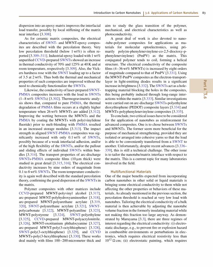
Introduction to Carbon Nanotubes 3.6 Applications of Carbon Nanotubes 83
dispersion into an epoxy matrix improves the interfacialload transfer, possibly by local stiffening of the matrixnear interface [3.308].
As for ceramic matrix composites, the electricalcharacteristics of SWNT- and MWNT-epoxy compos-ites are described with the percolation theory. Verylow percolation threshold (below 1 wt%) is often re-ported [3.309–311]. Industrial epoxy loaded with 1 wt%unpurified CCVD-prepared SWNTs showed an increasein thermal conductivity of 70% and 125% at 40 K and atroom temperature, respectively [3.309]. Also, the Vick-ers hardness rose with the SWNT loading up to a factorof 3.5 at 2 wt%. Thus both the thermal and mechanicalproperties of such composites are improved without theneed to chemically functionalize the SWNTs.
Likewise, the conductivity of laser-prepared SWNT-PMMA composites increases with the load in SWNTs(1–8 wt% SWNTs) [3.302]. Thermogravimetric analy-sis shows that, compared to pure PMMA, the thermaldegradation of PMMA films occurs at a slightly highertemperature when 26 wt% MWNTs are added [3.312].Improving the wetting between the MWNTs and thePMMA by coating the MWNTs with poly(vinylidenefluoride) prior to melt-blending with PMMA resultedin an increased storage modulus [3.313]. The impactstrength in aligned SWNT-PMMA composites was sig-nificantly increased with only 0.1 wt% of SWNTs,possibly because of a weak interfacial adhesion, and/orof the high flexibility of the SWNTs, and/or the pulloutand sliding effects of individual SWNTs within bun-dles [3.314]. The transport properties of arc-dischargeSWNTs-PMMA composite films (10 µm thick) werestudied in great detail [3.315, 316]. The electrical con-ductivity increases by nine orders of magnitude from0.1 to 8 wt% SWNTs. The room temperature conductiv-ity is again well described with the standard percolationtheory, confirming the good dispersion of the SWNTs inthe matrix.
Polymer composites with other matrices includeCCVD-prepared MWNT-polyvinyl alcohol [3.317],arc-prepared MWNT-polyhydroxyaminoether [3.318],arc-prepared MWNT-polyurethane acrylate [3.319,320], SWNT-polyurethane acrylate [3.321], SWNT-polycarbonate [3.322], MWNT-polyaniline [3.323],MWNT-polystyrene [3.324], SWNT-polyethylene[3.325], CCVD-prepared MWNT-polyacrylonitrile.[3.326], MWNT-oxotitanium phthalocyanine [3.327],arc-prepared MWNT-poly(3-octylthiophene) [3.328],SWNT-poly(3-octylthiophene) [3.329], and CCVDMWNTs-poly(3-hexylthiophene) [3.330]. These worksdeal mainly with films 100–200 micrometer thick and
aim to study the glass transition of the polymer,mechanical, and electrical characteristics as well asphotoconductivity.
A great deal of work is also devoted to nano--tube-polymer composites for applications as ma-terials for molecular optoelectronics, using pri-marily poly(m-phenylenevinylene-co-2,5-dioctoxy-p-phenylenevinylene) (PmPV) as the matrix. Thisconjugated polymer tends to coil, forming a helicalstructure. The electrical conductivity of the compositefilms (4–36 wt% MWNTs) is increased by eight ordersof magnitude compared to that of PmPV [3.331]. Usingthe MWNT-PmPV composites as the electron-transport-layer in light-emitting diodes results in a significantincrease in brightness [3.332]. The SWNTs act as a hole-trapping material blocking the holes in the composites,this being probably induced through long-range inter-actions within the matrix [3.333]. Similar investigationswere carried out on arc-discharge SWNTs-polyethylenedioxythiophene (PEDOT) composite layers [3.334] andMWNTs-polyphenylenevinylene composites [3.335].
To conclude, two critical issues have to be consideredfor the application of nanotubes as reinforcement foradvanced composites. One is to chose between SWNTsand MWNTs. The former seem more beneficial for thepurpose of mechanical strengthening, provided they areisolated or arranged into cohesive yarns so that the loadis able to be conveniently transferred from a SWNT toanother. Unfortunately, despite recent advances [3.336–339], this is still a technical challenge. The other issueis to tailor the nanotube/matrix interface with respect tothe matrix. This is a current topic for many laboratoriesinvolved in the field.
Multifunctional MaterialsOne of the major benefits expected from incorporatingcarbon nanotubes in other solid or liquid materials isbringing some electrical conductivity to them while notaffecting the other properties or behaviors of these ma-terials. As already mentioned in the previous section, thepercolation threshold is reached at very low load withnanotubes. Tailoring the electrical conductivity of a bulkmaterial is then achievable by adjusting the nanotubevolume fraction in the formerly insulating material whilenot making this fraction too large anyway. As demon-strated by Maruyama [3.3], there are three regimes ofinterest regarding the electrical conductivity: (i) electro-static discharge, e.g., to prevent fire or explosion hazardin combustible environments or perturbations in elec-tronics, which requires electrical resistivity less than1012 Ω cm; (ii) electrostatic painting, which requires
PartA
3.6
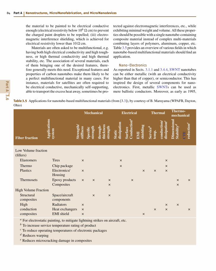
84 Part A Nanostructures, Micro/Nanofabrication, and Micro/Nanodevices
the material to be painted to be electrical conductiveenough (electrical resistivity below 106 Ω cm) to preventthe charged paint droplets to be repelled; (iii) electro-magnetic interference shielding, which is achieved forelectrical resistivity lower than 10 Ω cm.
Materials are often asked to be multifunctional, e.g.having both high electrical conductivity and high tough-ness, or high thermal conductivity and high thermalstability, etc. The association of several materials, eachof them bringing one of the desired features, there-fore generally meets this need. Exceptional features andproperties of carbon nanotubes make them likely to bea perfect multifunctional material in many cases. Forinstance, materials for satellites are often required tobe electrical conductive, mechanically self-supporting,able to transport the excess heat away, sometimes be pro-
Table 3.5 Applications for nanotube-based multifunctional materials (from [3.3]), by courtesy of B. Maruyama (WPAFB, Dayton,Ohio)
Mechanical Electrical Thermal Thermo-mechanical
Fiber fraction App
licat
ions
syst
em
Stre
ngth
/st
iffn
ess
Spec
ific
stre
ngth
thro
ugh-
thic
knes
sst
reng
th
Stat
icdi
ssip
atio
n
Surf
ace
Con
duct
iona
EM
Ish
ield
ing
Serv
iceb
tem
p.
cond
ucti
on/
diss
ipat
ionc
Dim
ensi
onal
Stab
ility
d
CT
Ere
duct
ione
Low Volume fraction(fillers)
Elastomers Tires × × ×
Thermo Chip package × ×Plastics Electronics/
Housing× × × ×
Thermosets Epoxy products × × × × × ×Composites × ×
High Volume FractionStructuralcomposites
Space/aircraftcomponents
× ×
High Radiators × × ×conduction Heat exchangers × × × ×composites EMI shield × ×
a For electrostatic painting, to mitigate lightning strikes on aircraft, etc.b To increase service temperature rating of productc To reduce operating temperatures of electronic packagesd Reduces warpinge Reduces microcracking damage in composites
tected against electromagnetic interferences, etc., whileexhibiting minimal weight and volume. All these proper-ties should be possible with a single nanotube-containingcomposite material instead of complex multi-materialscombining layers of polymers, aluminum, copper, etc.Table 3.5 provides an overview of various fields in whichnanotube-based multifunctional materials should find anapplication.
Nano-ElectronicsAs reported in Sects. 3.1.1 and 3.4.4, SWNT nanotubescan be either metallic (with an electrical conductivityhigher than that of copper), or semiconductor. This hasinspired the design of several components for nano-electronics. First, metallic SWNTs can be used asmere ballistic conductors. Moreover, as early as 1995,
PartA
3.6
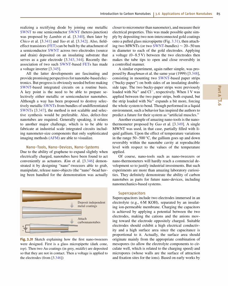
Introduction to Carbon Nanotubes 3.6 Applications of Carbon Nanotubes 85
realizing a rectifying diode by joining one metallicSWNT to one semiconductor SWNT (hetero-junction)was proposed by Lambin et al. [3.340], then later byChico et al. [3.341] and Yao et al. [3.342]. Also, field-effect transistors (FET) can be built by the attachment ofa semiconductor SWNT across two electrodes (sourceand drain) deposited on an insulating substrate thatserves as a gate electrode [3.343, 344]. Recently the-association of two such SWNT-based FETs has madea voltage inverter [3.345].
All the latter developments are fascinating andprovide promising perspectives for nanotube-based elec-tronics. But progress is obviously needed before makingSWNT-based integrated circuits on a routine basis.A key point is the need to be able to prepare se-lectively either metallic or semiconductor nanotubes.Although a way has been proposed to destroy selec-tively metallic SWNTs from bundles of undifferentiatedSWNTs [3.347], the method is not scalable and selec-tive synthesis would be preferable. Also, defect-freenanotubes are required. Generally speaking, it relatesto another major challenge, which is to be able tofabricate at industrial scale integrated circuits includ-ing nanometer-size components that only sophisticatedimaging methods (AFM) are able to visualize.
Nano-Tools, Nano-Devices, Nano-SystemsDue to the ability of graphene to expand slightly whenelectrically charged, nanotubes have been found to actconveniently as actuators. Kim et al. [3.346] demon-strated it by designing “nano”-tweezers able to grab,manipulate, release nano-objects (the “nano”-bead hav-ing been handled for the demonstration was actually
+–
Deposit independentmetal coatings
Attachcarbonnanotubes
Fig. 3.31 Sketch explaining how the first nano-tweezerswere designed. First is a glass micropipette (dark cone,top). Then two Au coatings (in grey, middle) are depositedso that they are not in contact. Then a voltage is applied tothe electrodes (from [3.346])
closer to micrometer than nanometer), and measure theirelectrical properties. This was made possible quite sim-ply by depositing two non-interconnected gold coatingsonto a pulled glass micropipette (Fig. 3.31), then attach-ing two MWNTs (or two SWNT-bundles) ∼ 20–50 nmin diameter to each of the gold electrodes. Applyinga voltage (0–8.5 V) between the two electrodes thenmakes the tube tips to open and close reversibly ina controlled manner.
A similar experiment, again rather simple, was pro-posed by Baughman et al. the same year (1999) [3.348],consisting in mounting two SWNT-based paper strips(“bucky-paper”) on both sides of an insulating double-side tape. The two bucky-paper strips were previouslyloaded with Na+ and Cl−, respectively. When 1 V wasapplied between the two paper strips, both expand, butthe strip loaded with Na+ expands a bit more, forcingthe whole system to bend. Though performed in a liquidenvironment, such a behavior has inspired the authors topredict a future for their system as “artificial muscles.”
Another example of amazing nano-tools is the nano-thermometer proposed by Gao et al. [3.349]. A singleMWNT was used, in that case, partially filled with li-quid gallium. Upon the effect of temperature variationsin the range 50–500 C, the gallium goes up and downreversibly within the nanotube cavity at reproduciblelevel with respect to the values of the temperatureapplied.
Of course, nano-tools such as nano-tweezers ornano-thermometers will hardly reach a commercial de-velopment so to justify industrial investments. But suchexperiments are more than amazing laboratory curiosi-ties. They definitely demonstrate the ability of carbonnanotubes as parts for future nano-devices, includingnanomechanics-based systems.
SupercapacitorsSupercapacitors include two electrodes immersed in anelectrolyte (e.g., 6 M KOH), separated by an insulat-ing ion-permeable membrane. Charging the capacitorsis achieved by applying a potential between the twoelectrodes, making the cations and the anions mov-ing toward the electrode oppositely charged. Suitableelectrodes should exhibit a high electrical conductiv-ity and a high surface area since the capacitance isproportional to it. Actually, the surface area shouldoriginate mainly from the appropriate combination ofmesopores (to allow the electrolyte components to cir-culate well, which is related to the charging speed) andmicropores (whose walls are the surface of attractionand fixation sites for the ions). Based on early works by
PartA
3.6
86 Part A Nanostructures, Micro/Nanofabrication, and Micro/Nanodevices
Niu et al. [3.350], such a combination was found to bereached with the specific architecture offered by packedand entangled h-MWNTs with a poor nanotexture (seeSect. 3.1.2). But, activation pre-treatments are neces-sary. For instance, a capacitor made from nanotubeswith surface area = 220 m2/g exhibited a capacitanceof 20 F/g, which increased up to 100 F/g after an ac-tivation treatment was applied to the nanotubes so thattheir surface area reaches 880 m2/g [3.126]. Alterna-tively, again due to their specific architecture inducedby their huge aspect ratio, nanotubes can also be used assupports for conductive polymer coatings, e.g., polypyr-role or polyaniline [3.351], which otherwise would make
a too dense phase (i. e. not allowing an easy circulationand penetration of ions). Supercapacitors built from suchcomposites can overcome more than 2,000 charging cy-cles, with current density as high as 350 mA/g [3.352].Capacitors including nanotubes already have capaci-tance as high as 180–200 F/g, i. e. equivalent to thatobtained with electrodes built from regular carbon ma-terials, with the advantage of faster charging [3.126].Current works will certainly lead to further optimiza-tion of both the nanotube material architecture andthe nanotube-supported conductive polymers, givingreasonable perspectives for the commercial use of nano-tubes as components for supercapacitors.
References
3.1 M. Hillert, N. Lange: The structure of graphite fila-ments, Zeitschr. Kristall. 111 (1958) 24–34
3.2 T. V. Hughes, C. R. Chambers: US Patent 405,480(1889)
3.3 B. Maruyama, K. Alam: Carbon nanotubes andnanofibers in composite materials, SAMPE J. 38(2002) 59–70
3.4 P. Schützenberger, L. Schützenberger: Sur quelquesfaits relatifs à l’histoire du carbone, C. R. Acad. Sci.Paris 111 (1890) 774–778
3.5 C. Pélabon, H. Pélabon: Sur une variété de carbonefilamenteux, C. R. Acad. Sci. (Paris) 137 (1903) 706–708
3.6 R. T. K. Baker, P. S. Harris: The formation of filament-ous carbon. In: Chemistry and Physics of Carbon,Vol. 14, ed. by P. L. Walker Jr., P. A. Thrower (Dekker,New York 1978) pp. 83–165
3.7 S. Iijima: Helical microtubules of graphite carbon,Nature 354 (1991) 56–58
3.8 S. Iijima, T. Ichihashi: Single-shell carbon nano-tubes of 1-nm diameter, Nature 363 (1993) 603–605
3.9 D. S. Bethune, C. H. Kiang, M. S. de Vries, G. Gorman,R. Savoy, J. Vazquez, R. Bayers: Cobalt-catalysedgrowth of carbon nanotubes with single-atomic-layer walls, Nature 363 (1993) 605–607
3.10 J. Tersoff, R. S. Ruoff: Structural properties ofa carbon-nanotube crystal, Phys. Rev. Lett. 73 (1994)676–679
3.11 N. Wang, Z. K. Tang, G. D. Li, J. S. Chen: Single-walled4 Å carbon nanotube arrays, Nature 408 (2000) 50–51
3.12 N. Hamada, S. I. Sawada, A. Oshiyama: New one-dimensional conductors, graphitemicrotubules, Phys.Rev. Lett. 68 (1992) 1579–1581
3.13 M. S. Dresselhaus, G. Dresselhaus, P. C. Eklund: Sci-ence of Fullerenes and Carbon Nanotubes (Academic,San Diego 1995)
3.14 M. Monthioux, B. W. Smith, B. Burteaux, A. Claye,J. Fisher, D. E. Luzzi: Sensitivity of single-wall
nanotubes to chemical processing: An electron mi-croscopy investigation, Carbon 39 (2001) 1261–1272
3.15 H. Allouche, M. Monthioux: Chemical vapor deposi-tion of pyrolytic carbon onto carbon nanotubes II –Structure and texture, Carbon (2003) accepted
3.16 M. Audier, A. Oberlin, M. Oberlin, M. Coulon, L. Bon-netain: Morphology and crystalline order in catalyticcarbons, Carbon 19 (1981) 217–224
3.17 Y. Saito: Nanoparticles and filled nanocapsules, Car-bon 33 (1995) 979–988
3.18 P. J. F. Harris: Carbon Nanotubes and Related Struc-tures (Cambridge Univ. Press, Cambridge 1999)
3.19 N. M. Rodriguez, A. Chambers, R. T. Baker: Catalyticengineering of carbon nanostructures, Langmuir 11(1995) 3862–3866
3.20 H. W. Kroto, J. R. Heath, S.C. O’Brien, R. F. Curl,R. E. Smalley: C60 Buckminsterfullerene, Nature 318(1985) 162–163
3.21 W. Krätschmer, L. D. Lamb, K. Fostiropoulos,D. R. Huffman: Solid C60: A new form of carbon,Nature 347 (1990) 354–358
3.22 T. Guo, P. Nikolaev, A. G. Rinzler, D. Tomanek,D. T. Colbert, R. E. Smalley: Self-assembly of tubularfullerenes, J. Phys. Chem. 99 (1995) 10694–10697
3.23 T. Guo, P. Nikolaev, A. Thess, D. T. Colbert, R. E. Smal-ley: Catalytic growth of single-walled nanotubesby laser vaporisation, Chem. Phys. Lett. 243 (1995)49–54
3.24 A. G. Rinzler, J. Liu, H. Dai, P. Nikolaev, C. B. Huff-man, F. J. Rodriguez-Macias, P. J. Boul, A. H. Lu,D. Heymann, D. T. Colbert, R. S. Lee, J. E. Fischer,A. M. Rao, P. C. Eklund, R. E. Smalley: Large scale pu-rification of single wall carbon nanotubes: Process,product and characterization, Appl. Phys. A 67 (1998)29–37
3.25 A. Thess, R. Lee, P. Nikolaev, H. Dai, P. Petit,J. Robert, C. Xu, Y. H. Lee, S. G. Kim, D. T. Colbert,G. Scuseria, D. Tomanek, J. E. Fischer, R. E. Smal-
PartA
3
Introduction to Carbon Nanotubes References 87
ley: Crystalline ropes of metallic carbon nanotubes,Science 273 (1996) 487–493
3.26 L. M. de la Chapelle, J. Gavillet, J. L. Cochon, M. Ory,S. Lefrant, A. Loiseau, D. Pigache: A continuouswave CO2 laser reactor for nanotube synthesis, Proc.Electronic Properties Novel Materials-XVI Int. Win-terschool – AIP Conf. Proc., Melville 1999, ed. byH. Kuzmany, J. Fink, M. Mehring, S. Roth (Springer,Berlin, Heidelberg 1999) 486 237– 240
3.27 M. Yudasaka, T. Komatsu, T. Ichihashi, S. Iijima:Single wall carbon nanotube formation by laser ab-lation using double targets of carbon and metal,Chem. Phys. Lett. 278 (1997) 102–106
3.28 M. Castignolles, A. Foutel-Richard, A. Mavel, J. L. Co-chon, D. Pigache, A. Loiseau, P. Bernier: Combinedexperimental and numerical study of the pa-rameters controlling the C-SWNT synthesis vialaser vaporization, Proc. Electronic Properties ofNovel Materials-XVI Int. Winterschool – AIP Conf.Proc., Melville 2002, ed. by H. Kuzmany, J. Fink,M. Mehring, S. Roth (Springer, Berlin, Heidelberg2002) 633 385–389
3.29 T. W. Ebbesen, P. M. Ajayan: Large-scale synthesis ofcarbon nanotubes, Nature 358 (1992) 220–221
3.30 D. Ugarte: Morphology and structure of graphiticsoot particles generated in arc-discharge C60 pro-duction, Chem. Phys. Lett. 198 (1992) 596–602
3.31 T. W. Ebbesen: Carbon nanotubes, Ann. Rev. Mater.Sci. 24 (1994) 235–264
3.32 T. Beltz, J. Find, D. Herein, N. Pfänder, T. Rühle,H. Werner, M. Wohlers, R. Schlögl: On the productionof different carbon forms by electric arc graphiteevaporation, Ber. Bunsenges. Phys. Chem. 101 (1997)712–725
3.33 C. Journet, W. K. Maser, P. Bernier, A. Loiseau,L. M. de la Chapelle, S. Lefrant, P. Deniard,R. Lee, J. E. Fischer: Large-scale production ofsingle-walled carbon nanotubes by the electric-arctechnique, Nature 388 (1997) 756–758
3.34 K. Saïdane, M. Razafinimanana, H. Lange, M. Baltas,A. Gleizes, J. J. Gonzalez: Influence of the carbon arccurrent intensity on fullerene synthesis, Proc. 24thInt. Conf. on Phenomena in Ionized Gases, Warsaw1999, ed. by P. Pisarczyk, T. Pisarczyk, J. Wotowski,203–204
3.35 H. Allouche, M. Monthioux, M. Pacheco, M. Razafini-manana, H. Lange, A. Huczko, T. P. Teulet, A. Gleizes,T. Sogabe: Physical characteristics of the graphite-electrode electric-arc as parameters for the for-mation of single-wall carbon nanotubes, Proc.Eurocarbon (Deutsche Keram. Ges., Berlin 2000)1053–1054
3.36 M. Razafinimanana, M. Pacheco, M. Monthioux,H. Allouche, H. Lange, A. Huczko, A. Gleizes:Spectroscopic study of an electric arc with Gdand Fe doped anodes for the carbon nanotubeformation, Proc. 25th Int. Conf. on Phenomenain Ionized Gases, Nagoya 2001, ed. by E. Goto
(Nagoya Univ., Nagoya 2001) Extend. Abstr. 3 297–298
3.37 M. Razafinimanana, M. Pacheco, M. Monthioux,H. Allouche, H. Lange, A. Huczko, P. Teulet,A. Gleizes, C. Goze, P. Bernier, T. Sogabe: Influence ofdoped graphite electrode in electric arc for the for-mation of single wall carbon nanotubes, Proc. 6thEur. Conf. on Thermal Plasma Processes – Progressin Plasma Processing of Materials, New York 2000,ed. by P. Fauchais (Begell House, New York 2001)649–654
3.38 M. Pacheco, H. Allouche, M. Monthioux, A. Razafini-manana, A. Gleizes: Correlation between the plasmacharacteristics and the morphology and structureof the carbon phases synthesised by electric arcdischarge, Proc. 25th Biennial Conf. on Carbon,Lexington 2001 (Univ. of Kentucky, Lexington 2001)Extend. Abstr.(CD-Rom), Novel/14.1
3.39 M. Pacheco, M. Monthioux, M. Razafinimanana,L. Donadieu, H. Allouche, N. Caprais, A. Gleizes: Newfactors controlling the formation of single-wall car-bon nanotubes by arc plasma, Proc. Carbon 2002Int. Conf., Beijing 2002 (Tsinghua Univ., Beijing 2002)(CD-Rom/Oral/I014)
3.40 M. Monthioux, M. Pacheco, H. Allouche, M. Razafin-imanana, N. Caprais, L. Donnadieu, A. Gleizes: Newdata about the formation of SWNTs by the elec-tric arc method, Electronic Properties of MolecularNanostructures, AIP Conf. Proc., Melville 2002, ed. byH. Kuzmany, J. Fink, M. Mehring, S. Roth (Springer,Berlin, Heidelberg 2002) 182–185
3.41 H. Lange, A. Huczko, M. Sioda, M. Pacheco,M. Razafinimanana, A. Gleizes: Influence ofgadolinium on carbon arc plasma and formationof fullerenes and nanotubes, Plasma Chem. PlasmaProcess 22 (2002) 523–536
3.42 C. Journet: La production de nanotubes de carbone.Ph.D. Thesis (University of Montpellier II, Montpellier1998)
3.43 T. Sogabe, T. Masuda, K. Kuroda, Y. Hirohaya,T. Hino, T. Ymashina: Preparation of B4C-mixedgraphite by pressureless sintering and its air oxi-dation behavior, Carbon 33 (1995) 1783–1788
3.44 M. Ishigami, J. Cumings, A. Zettl, S. Chen: A sim-ple method for the continuous production of carbonnanotubes, Chem. Phys. Lett. 319 (2000) 457–459
3.45 Y. L. Hsin, K. C. Hwang, F. R. Chen, J. J. Kai: Produc-tion and in-situ metal filling of carbon nanotube inwater, Adv. Mater. 13 (2001) 830–833
3.46 H. W. Zhu, X. S. Li, B. Jiang, C. L. Xu, C. L. Zhu,Y. F. Zhu, D. H. Wu, X. H. Chen: Formation of carbonnanotubes in water by the electric arc technique,Chem. Phys. Lett. 366 (2002) 664–669
3.47 W. K. Maser, P. Bernier, J. M. Lambert, O. Stephan,P. M. Ajayan, C. Colliex, V. Brotons, J. M. Planeix,B. Coq, P. Molinie, S. Lefrant: Elaboration andcharacterization of various carbon nanostructures,Synth. Met. 81 (1996) 243–250
PartA
3
88 Part A Nanostructures, Micro/Nanofabrication, and Micro/Nanodevices
3.48 J. Gavillet, A. Loiseau, J. Thibault, A. Maigné,O. Stéphan, P. Bernier: TEM study of the influ-ence of the catalyst composition on the formationand growth of SWNT, Proc. Electronic PropertiesNovel Materials-XVI Int. Winterschool – AIP Conf.Proc., Melville 2002, ed. by H. Kuzmany, J. Fink,M. Mehring, S. Roth (Springer, Berlin, Heidelberg2002) 633 202–206
3.49 L. P. F. Chibante, A. Thess, J. M. Alford, M. D. Diener,R. E. Smalley: Solar generation of the fullerenes,J. Phys. Chem. 97 (1993) 8696–8700
3.50 C. L. Fields, J. R. Pitts, M. J. Hale, C. Bingham,A. Lewandowski, D. E. King: Formation of fullerenesin highly concentrated solar flux, J. Phys. Chem. 97(1993) 8701–8702
3.51 P. Bernier, D. Laplaze, J. Auriol, L. Barbedette,G. Flamant, M. Lebrun, A. Brunelle, S. Della-Negra:Production of fullerenes from solar energy, Synth.Met. 70 (1995) 1455–1456
3.52 M. J. Heben, T. A. Bekkedhal, D. L. Schultz,K. M. Jones, A. C. Dillon, C. J. Curtis, C. Bingham,J. R. Pitts, A. Lewandowski, C. L. Fields: Productionof single wall carbon nanotubes using concen-trated sunlight, Proc. Symp. Recent Adv. Chem. Phys.Fullerenes Rel. Mater., Pennington 1996, ed. byK. M. Kadish, R. S. Ruoff (Electrochemical Society,Pennington 1996) INC 3 803–811
3.53 D. Laplaze, P. Bernier, C. Journet, G. Vié, G. Fla-mant, E. Philippot, M. Lebrun: Evaporation ofgraphite using a solar furnace, Proc. 8th Int. Symp.Solar Concentrating Technol., Köln 1996, ed. byM. Becker, M. Balmer (C. F. Müller Verlag, Heidelberg1997)
3.54 D. Laplaze, P. Bernier, W. K. Maser, G. Flamant,T. Guillard, A. Loiseau: Carbon nanotubes : The solarapproach, Carbon 36 (1998) 685–688
3.55 T. Guillard, S. Cetout, L. Alvarez, J. L. Sauvajol,E. Anglaret, P. Bernier, G. Flamant, D. Laplaze: Pro-duction of carbon nanotubes by the solar route, Eur.Phys. J. 5 (1999) 251–256
3.56 G. Flamant, D. Luxembourg, C. Mas, D. Laplaze:Carbon nanotubes from solar energy; a chemical en-gineering approach of the scale up, Proc. Am. Inst.Chem. Eng. Ann. Meeting, Indianapolis 2002, in print
3.57 G. G. Tibbets, M. Endo, C. P. Beetz: Carbon fibersgrown from the vapor phase: A novel material,SAMPE J. 22 (1989) 30
3.58 R. T. K. Baker: Catalytic growth of carbon filaments,Carbon 27 (1989) 315–323
3.59 R. T. K. Baker, P. S. Harris, R. B. Thomas, R. J. Waite:Formation of filamentous carbon from iron, cobalt,and chromium catalyzed decomposition of acety-lene, J. Catal. 30 (1973) 86–95
3.60 T. Koyama, M. Endo, Y. Oyuma: Carbon fibersobtained by thermal decomposition of vaporizedhydrocarbon, Jap. J. Appl. Phys. 11 (1972) 445–449
3.61 M. Endo, A. Oberlin, T. Koyama: High resolutionelectron microscopy of graphitizable carbon fiber
prepared by benzene decomposition, Jap. J. Appl.Phys. 16 (1977) 1519–1523
3.62 N. M. Rodriguez: A review of catalytically grown car-bon nanofibers, J. Mater. Res. 8 (1993) 3233–3250
3.63 W. R. Davis, R. J. Slawson, G. R. Rigby: An unusualform of carbon, Nature 171 (1953) 756
3.64 H. P. Boehm: Carbon from carbon monoxide dis-proportionation on nickel and iron catalysts;morphological studies and possible growth mech-anisms, Carbon 11 (1973) 583–590
3.65 M. Audier, A. Oberlin, M. Coulon: Crystallographicorientations of catalytic particles in filamentous car-bon; case of simple conical particles, J. Cryst. Growth55 (1981) 546–549
3.66 M. Audier, M. Coulon: Kinetic and microscopic as-pects of catalytic carbon growth, Carbon 23 (1985)317–323
3.67 M. Audier, A. Oberlin, M. Coulon: Study of biconicmicrocrystals in the middle of carbon tubes obtainedby catalytic disproportionation of CO, J. Cryst. Growth57 (1981) 524–534
3.68 A. Thaib, G. A. Martin, P. Pinheiro, M. C. Schouler,P. Gadelle: Formation of carbon nanotubes from thecarbon monoxide disproportionation reaction overCO/Al2O′ and Co/SiO′ catalysts, Catal. Lett. 63 (1999)135–141
3.69 P. Pinheiro, M. C. Schouler, P. Gadelle, M. Mermoux,E. Dooryhée: Effect of hydrogen on the orientation ofcarbon layers in deposits from the carbon monoxidedisproportionation reaction over Co/Al2O3 catalysts,Carbon 38 (2000) 1469–1479
3.70 P. Pinheiro, P. Gadelle: Chemical state of a sup-ported iron-cobalt catalyst during CO disproportion-ation. I. Thermodynamic study, J. Phys. Chem. Solids62 (2001) 1015–1021
3.71 P. Pinheiro, P. Gadelle, C. Jeandey, J. L. Oddou:Chemical state of a supported iron-cobalt cata-lyst during CO disproportionation. II. Experimentalstudy, J. Phys. Chem. Solids 62 (2001) 1023–1037
3.72 C. Laurent, E. Flahaut, A. Peigney, A. Rousset: Metalnanoparticles for the catalytic synthesis of carbonnanotubes, New J. Chem. 22 (1998) 1229–1237
3.73 A. Peigney, C. Laurent, F. Dobigeon, A. Rousset: Car-bon nanotubes grown in situ by a novel catalyticmethod, J. Mater. Res. 12 (1997) 613–615
3.74 V. Ivanov, J. B. Nagy, P. Lambin, A. Lucas,X. B. Zhang, X. F. Zhang, D. Bernaerts, G. Van Ten-deloo, S. Amelinckx, J. Van Landuyt: The study ofnanotubules produced by catalytic method, Chem.Phys. Lett. 223 (1994) 329–335
3.75 V. Ivanov, A. Fonseca, J. B. Nagy, A. Lucas, P. Lambin,D. Bernaerts, X. B. Zhang: Catalytic production andpurification of nanotubules having fullerene-scalediameters, Carbon 33 (1995) 1727–1738
3.76 K. Hernadi, A. Fonseca, J. B. Nagy, D. Bernaerts,A. Fudala, A. Lucas: Catalytic synthesis of carbonnanotubes using zeolite support, Zeolites 17 (1996)416–423
PartA
3
Introduction to Carbon Nanotubes References 89
3.77 H. Dai, A. G. Rinzler, P. Nikolaev, A. Thess, D. T. Col-bert, R. E. Smalley: Single-wall nanotubes producedby metal-catalysed disproportionation of carbonmonoxide, Chem. Phys. Lett. 260 (1996) 471–475
3.78 A. M. Cassel, J. A. Raymakers, J. Kong, H. Dai: Largescale CVD synthesis of single-walled carbon nano-tubes, J. Phys. Chem. B 109 (1999) 6484–6492
3.79 B. Kitiyanan, W. E. Alvarez, J. H. Harwell, D. E. Re-sasco: Controlled production of single-wall carbonnanotubes by catalytic decomposition of CO onbimetallic Co-Mo catalysts, Chem. Phys. Lett. 317(2000) 497–503
3.80 E. Flahaut: Synthèse par voir catalytique et carac-térisation de composites nanotubes de carbone-metal-oxyde Poudres et matériaux denses. Ph.D.Thesis (Univers. Paul Sabatier, Toulouse 1999)
3.81 A. Govindaraj, E. Flahaut, C. Laurent, A. Peigney,A. Rousset, C. N. R. Rao: An investigation of car-bon nanotubes obtained from the decomposition ofmethane over reduced Mg1−xMxAl2O4 spinel cata-lysts, J. Mater. Res. 14 (1999) 2567–2576
3.82 E. Flahaut, A. Peigney, C. Laurent, A. Rousset: Syn-thesis of single-walled carbon nanotube-Co-MgOcomposite powders and extraction of the nano-tubes, J. Mater. Chem. 10 (2000) 249–252
3.83 J. Kong, A. M. Cassel, H. Dai: Chemical vapordeposition of methane for single-walled carbonnanotubes, Chem. Phys. Lett. 292 (1998) 567–574
3.84 R. Marangoni, P. Serp, R. Feurrer, Y. Kihn, P. Kalck,C. Vahlas: Carbon nanotubes produced by substratefree metalorganic chemical vapor deposition of ironcatalyst and ethylene, Carbon 39 (2001) 443–449
3.85 R. Sen, A. Govindaraj, C. N. R. Rao: Carbon nano-tubes by the metallocene route, Chem. Phys. Lett.267 (1997) 276–280
3.86 Y. Y. Fan, H. M. Cheng, Y. L. Wei, G. Su, S. H. Shen: Theinfluence of preparation parameters on the massproduction of vapor grown carbon nanofibers, Car-bon 38 (2000) 789–795
3.87 L. Ci, J. Wei, B. Wei, J. Liang, C. Xu, D. Wu: Carbonnanofibers and single-walled carbon nanotubesprepared by the floating catalyst method, Carbon39 (2001) 329–335
3.88 O. A. Nerushev, M. Sveningsson, L. K. L. Falk,F. Rohmund: Carbon nanotube films obtained bythermal vapour deposition, J. Mater. Chem. 11 (2001)1122–1132
3.89 F. Rohmund, L. K. L. Falk, F. E. B. Campbell: A sim-ple method for the production of large arrays ofaligned carbon nanotubes, Chem. Phys. Lett. 328(2000) 369–373
3.90 G. G. Tibbets, C. A. Bernardo, D. W. Gorkiewicz,R. L. Alig: Role of sulfur in the production of carbonfibers in the vapor phase, Carbon 32 (1994) 569–576
3.91 W. Q. Han, P. Kholer-Riedlich, T. Seeger, F. Ernst,M. Ruhle, N. Grobert, W. K. Hsu, B. H. Chang,Y. Q. Zhu, H. W. Kroto, M. Terrones, H. Terrones:Aligned CNx nanotubes by pyrolysis of ferrocene
under NH3 atmosphere, Appl. Phys. Lett. 77 (2000)1807–1809
3.92 R. E. Smalley, J. H. Hafner, D. T. Colbert, K. Smith:Catalytic growth of single-wall carbon nanotubesfrom metal particles, US patent US19980601010903(1998)
3.93 T. Kyotani, L. F. Tsai, A. Tomita: Preparation of ul-trafine carbon tubes in nanochannels of an anodicaluminum oxide film, Chem. Mater. 8 (1996) 2109–2113
3.94 W. K. Hsu, J. P. Hare, M. Terrones, H. W. Kroto,D. R. M. Walton, P. J. F. Harris: Condensed-phasenanotubes, Nature 377 (1995) 687
3.95 W. S. Cho, E. Hamada, Y. Kondo, K. Takayanagi: Syn-thesis of carbon nanotubes from bulk polymer, Appl.Phys. Lett. 69 (1996) 278–279
3.96 Y. L. Li, Y. D. Yu, Y. Liang: A novel method for syn-thesis of carbon nanotubes: Low temperature solidpyrolysis, J. Mater. Res. 12 (1997) 1678–1680
3.97 S. Fan, M. Chapline, N. Franklin, T. Tombler,A. M. Cassel, H. Dai: Self-oriented regular arrays ofcarbon nanotubes and their field emission proper-ties, Science 283 (1999) 512–514
3.98 M. L. Terranova, S. Piccirillo, V. Sessa, P. Sbornicchia,M. Rossi, S. Botti, D. Manno: Growth of single-walledcarbon nanotubes by a novel technique using nano-sized graphite as carbon source, Chem. Phys. Lett.327 (2000) 284–290
3.99 R. L. Vander Wal, T. Ticich, V. E. Curtis: Diffusion flamesynthesis of single-walled carbon nanotubes, Chem.Phys. Lett. 323 (2000) 217–223
3.100 Y. Y. Wei, G. Eres, V. I. Merkulov, D. H. Lowdens: Ef-fect of film thickness on carbon nanotube growthby selective area chemical vapor deposition, Appl.Phys. Lett. 78 (2001) 1394–1396
3.101 W. Z. Li, S. S. Xie, L. X. Qian, B. H. Chang, B. S. Zou,W. Y. Zhou, R. A. Zha, G. Wang: Large scale synthe-sis of aligned carbon nanotubes, Science 274 (1996)1701–1703
3.102 F. Zheng, L. Liang, Y. Gao, J. H. Sukamto, L. Aardahl:Carbon nanotubes synthesis using mesoporous silicatemplates, Nanolett. 2 (2002) 729–732
3.103 S. H. Jeong, O.-K. Lee, K. H. Lee, S. H. Oh, C. G. Park:Preparation of aligned carbon nanotubes withprescribed dimension: Template synthesis and son-ication cutting approach, Chem. Mater. 14 (2002)1859–1862
3.104 N. S. Kim, Y. T. Lee, J. Park, H. Ryu, H. J. Lee, S. Y. Choi,J. Choo: Dependence of vertically aligned growth ofcarbon nanotubes on catalyst, J. Phys. Chem. B 106(2002) 9286–9290
3.105 C. J. Lee, D. W. Kim, T. J. Lee, Y. C. Choi, Y. S. Park,Y. H. Lee, W. B. Choi, N. S. Lee, G.-S. Park, J. M. Kim:Synthesis of aligned carbon nanotubes using ther-mal chemical vapor deposition, Chem. Phys. Lett.312 (1999) 461–468
3.106 W. D. Zhang, Y. Wen, S. M. Liu, W. C. Tjiu, G. Q. Xu,L. M. Gan: Synthesis of vertically aligned carbon
PartA
3
90 Part A Nanostructures, Micro/Nanofabrication, and Micro/Nanodevices
nanotubes on metal deposited quartz plates, Carbon40 (2002) 1981–1989
3.107 S. Huang, L. Dai, A. W. H. Mau: Controlled fabricationof large scale aligned carbon nanofiber/nanotubepatterns by photolithography, Adv. Mater. 14 (2002)1140–1143
3.108 R. Andrews, D. Jacques, A. M. Rao, F. Derbyshire,D. Qian, X. Fan, E. C. Dickey, J. Chen: Continous pro-duction of aligned carbon nanotubes: A step closerto commercial realization, Chem. Phys. Lett. 303(1999) 467–474
3.109 C. N. R. Rao, R. Sen, B. C. Satishkumar, A. Govin-daraj: Large aligned carbon nanotubes bundles fromferrocene pyrolysis, Chem. Commun. 15 (1998) 1525–1526
3.110 X. Zhang, A. Cao, B. Wei, Y. Li, J. Wei, C. Xu, D. Wu:Rapid growth of well-aligned carbon nanotube ar-rays, Chem. Phys. Lett. 362 (2002) 285–290
3.111 X. Zhang, A. Cao, Y. Li, C. Xu, J. Liang, D. Wu, B. Wei:Self-organized arrays of carbon nanotube ropes,Chem. Phys. Lett. 351 (2002) 183–188
3.112 K. S. Choi, Y. S. Cho, S. Y. Hong, J. B. Park, D. J. Kim:Effects of ammonia on the alignment of carbonnanotubes in metal-assisted chemical vapor depo-sition, J. Eur. Cer. Soc. 21 (2001) 2095–2098
3.113 M. Endo, H. W. Kroto: Formation of carbonnanofibers, J. Phys. Chem. 96 (1992) 6941–6944
3.114 R. S. Wagner: VLS mechanisms of crystal growth. In:Whisker Technology, ed. by P. Levit A. (Wiley, NewYork 1970) pp. 47–72
3.115 Y. H. Lee, S. G. Kim, D. Tomanek: Catalytic growth ofsingle-wall carbon nanotubes: An ab initio study,Phys. Rev. Lett. 78 (1997) 2393–2396
3.116 H. Dai: Carbon Nanotubes: Synthesis, integration,and properties, Acc. Chem. Res. 35 (2002) 1035–1044
3.117 Y. Saito, M. Okuda, N. Fujimoto, T. Yoshikawa,M. Tomita, T. Hayashi: Single-wall carbon nanotubesgrowing radially from Ni fine particles formed by arcevaporation, Jpn. J. Appl. Phys. 33 (1994) L526–L529
3.118 J. Bernholc, C. Brabec, M. Buongiorno Nardelli,A. Malti, C. Roland, B. J. Yakobson: Theory of growthand mechanical properties of nanotubes, Appl.Phys. A 67 (1998) 39–46
3.119 M. Pacheco: Synthèse des nanotubes de carbone pararc electrique. Ph.D. Thesis (Université Toulouse III,Toulouse 2003)
3.120 K. Méténier, S. Bonnamy, F. Béguin, C. Jour-net, P. Bernier, L. M. de la Chapelle, O. Chauvet,S. Lefrant: Coalescence of single walled nanotubesand formation of multi-walled carbon nanotubesunder high temperature treatments, Carbon 40(2002) 1765–1773
3.121 P. G. Collins, P. Avouris: Nanotubes for electronics,Sci. Am. 283 (2000) 38–45
3.122 Q.-H. Yang, P. X. Hou, S. Bai, M. Z. Wang,H. M. Cheng: Adsorption and capillarity of nitro-gen in aggregated multi-walled carbon nanotubes,Chem. Phys. Lett. 345 (2001) 18–24
3.123 S. Inoue, N. Ichikuni, T. Suzuki, T. Uematsu,K. Kaneko: Capillary condensation of N2 on multi-wall carbon nanotubes, J. Phys. Chem. 102 (1998)4689–4692
3.124 M. Eswaramoorthy, R. Sen, C. N. R. Rao: A study ofmicropores in single-walled carbon nanotubes bythe adsorption of gases and vapors, Chem. Phys.Lett. 304 (1999) 207–210
3.125 A. Peigney, Ch. Laurent, E. Flahaut, R. R. Bacsa,A. Rousset: Specific surface area of carbon nano-tubes and bundles of carbon nanotubes, Carbon 39(2001) 507–514
3.126 E. Frackowiak, S. Delpeux, K. Jurewicz, K. Szostak,D. Cazorla-Amoros, F. Béguin: Enhanced capacitanceof carbon nanotubes through chemical activation,Chem. Phys. Lett. 336 (2002) 35–41
3.127 M. Muris, N. Dupont-Pavlosky, M. Bienfait, P. Zep-penfeld: Where are the molecules adsorbed onsingle-walled nanotubes?, Surf. Sci. 492 (2001) 67–74
3.128 A. Fujiwara, K. Ishii, H. Suematsu, H. Kataura,Y. Maniwa, S. Suzuki, Y. Achiba: Gas adsorptionin the inside and outside of single-walled carbonnanotubes, Chem. Phys. Lett. 336 (2001) 205–211
3.129 C. M. Yang, H. Kanoh, K. Kaneko, M. Yudasaka,S. Iijima: Adsorption behaviors of HiPco single-walled carbon nanotubes aggregates for alcoholvapors, J. Phys. Chem. 106 (2002) 8994–8999
3.130 J. Zhao, A. Buldum, J. Han, J. P. Lu: Gas moleculeadsorption in carbon nanotubes and nanotube bun-dles, Nanotechnology 13 (2002) 195–200
3.131 K. A. Williams, P. C. Eklund: Monte Carlo simulationof H2 physisorption in finite diameter carbon nano-tube ropes, Chem. Phys. Lett. 320 (2000) 352–358
3.132 A. Chambers, C. Park, R. T. K. Baker, N. Rodriguez:Hydrogen storage in graphite nanofibers, J. Phys.Chem. B. 102 (1998) 4253–4256
3.133 J. Hilding, E. A. Grulke, S. B. Sinnott, D. Qian, R. An-drews, M. Jagtoyen: Sorption of butane on carbonmultiwall nanotubes at room temperature, Lang-muir 17 (2001) 7540–7544
3.134 K. Masenelli-Varlot, E. McRae, N. Dupont-Pavlosky:Comparative adsorption of simple molecules oncarbon nanotubes. Dependence of the adsorptionproperties on the nanotube morphology, Appl. Surf.Sci. 196 (2002) 209–215
3.135 D. J. Browning, M. L. Gerrard, J. B. Lakeman,I. M. Mellor, R. J. Mortimer, M. C. Turpin: Studies intothe storage of hydrogen in carbon nanofibers: Pro-posal of a possible mechanism, Nanolett. 2 (2002)201–205
3.136 F. H. Yang, R. T. Yang: Ab initio molecular orbitalstudy of adsorption of atomic hydrogen on graphite:insight into hydrogen storage in carbon nanotubes,Carbon 40 (2002) 437–444
3.137 G. E. Froudakis: Why alkali-metal-doped car-bon nanotubes possess high hydrogen uptake,Nanolett. 1 (2001) 531–533
PartA
3
Introduction to Carbon Nanotubes References 91
3.138 H. Ulbricht, G. Moos, T. Hertel: Physisorption ofmolecular oxygen on single-wall carbon nano-tube bundles and graphite, Phys. Rev. B 66 (2002)075404-1-075404-7
3.139 H. Ulbricht, J. Kriebel, G. Moos, T. Hertel: Desorptionkinetics and interaction of Xe with single-wall car-bon nanotube bundles, Chem. Phys. Lett. 363 (2002)252–260
3.140 R. Saito, G. Dresselhaus, M. S. Dresselhaus: Physi-cal Properties of Carbon Nanotubes (Imperial CollegePress, London 1998)
3.141 A. Charlier, E. McRae, R. Heyd, M. F. Charlier,D. Moretti: Classification for double-walled carbonnanotubes, Carbon 37 (1999) 1779–1783
3.142 A. Charlier, E. McRae, R. Heyd, M. F. Charlier:Metal semi-conductor transitions under uniax-ial stress for single- and double-walled carbonnanotubes, J. Phys. Chem. Solids 62 (2001) 439–444
3.143 H. Ajiki, T. Ando: Electronic states of carbon nano-tubes, J. Phys. Soc. Jap. 62 (1993) 1255–1266
3.144 C. T. White, T. N. Todorov: Carbon nanotubes as longballistic conductors, Nature 393 (1998) 240–242
3.145 S. Frank, P. Poncharal, Z. L. Wang, W. A. de Heer: Car-bon nanotube quantum resistors, Science 280 (1998)1744–1746
3.146 W. Liang, M. Bockrath, D. Bozovic, J. H. Hafner,M. Tinkham, H. Park: Fabry–Perot interference ina nanotube electron waveguide, Nature 411 (2001)665–669
3.147 L. Langer, V. Bayot, E. Grivei, J.-P. Issi, J.-P. Here-mans, C. H. Olk, L. Stockman, C. van Haesendonck,Y. Buynseraeder: Quantum transport in a multi-walled carbon nanotube, Phys. Rev. Lett. 76 (1996)479–482
3.148 M. Bockrath, D. H. Cobden, J. Lu, A. G. Rinzler,R. E. Smalley, L. Balents, P. L. McEuen: Luttinger-liquid behaviour in carbon nanotubes, Nature 397(1999) 598–601
3.149 K. Liu, S. Roth, G. S. Duesberg, G. T. Kim, D. Popa,K. Mukhopadhyay, R. Doome, J. B’Nagy: Antilo-calization in multiwalled carbon nanotubes, Phys.Rev. B 61 (2000) 2375–2379
3.150 Y. A. Kasumov, R. Deblock, M. Kociak, B. Reulet,H. Bouchiat, I. I. Khodos, Y. B. Gorbatov, V. T. Volkov,C. Journet, M. Burghard: Supercurrents throughsingle-walled carabon nanotubes, Science 284(1999) 1508–1511
3.151 B. W. Alphenaar, K. Tsukagoshi, M. Wagner: Magne-toresistance of ferromagnetically contacted carbonnanotubes, Phys. Eng. 10 (2001) 499–504
3.152 P. M. Ajayan, M. Terrrones, A. de la Guardia, V. Hue,N. Grobert, B. Q. Wei, H. Lezec, G. Ramanath,T. W. Ebbesen: Nanotubes in a flash – Ignition andreconstruction, Science 296 (2002) 705
3.153 S. Berber, Y. Kwon, D. Tomanek: Unusually highthermal conductivity of carbon nanotubes, Phys.Rev. Lett. 84 (2000) 4613–4616
3.154 S. N. Song, X. K. Wang, R. P. H. Chang, J. B. Ketterson:Electronic properties of graphite nanotubules fromgalvanomagnetic effects, Phys. Rev. Lett. 72 (1994)697–700
3.155 M.-F. Yu, O. Lourie, M. J. Dyer, K. Moloni, T. F. Kel-ley, R. S. Ruoff: Strength and breaking mechanism ofmultiwalled carbon nanotubes under tensile load,Science 287 (2000) 637–640
3.156 D. A. Walters, L. M. Ericson, M. J. Casavant, J. Liu,D. T. Colbert, K. A. Smith, R. E. Smalley: Elasticstrain of freely suspended single-wall carbon nano-tube ropes, Appl. Phys. Lett. 74 (1999) 3803–3805
3.157 B. G. Demczyk, Y. M. Wang, J. Cumingd, M. Hetamn,W. Han, A. Zettl, R. O. Ritchie: Direct mechanicalmeasurement of the tensile strength and eleasticmodulus of multiwalled carbon nanotubes, Mater.Sci. Eng. A 334 (2002) 173–178
3.158 R. P. Gao, Z. L. Wang, Z. G. Bai, W. A. De Heer,L. M. Dai, M. Gao: Nanomechanics of inidividualcarbon nanotubes from pyrolytically grown arrays,Phys. Rev. Lett. 85 (2000) 622–625
3.159 M. M. J. Treacy, T. W. Ebbesen, J. M. Gibson: Ex-ceptionally high Young’s modulus observed forindividual carbon nanotubes, Nature 381 (1996)678–680
3.160 N. Yao, V. Lordie: Young’s modulus of single-wallcarbon nanotubes, J. Appl. Phys. 84 (1998) 1939–1943
3.161 O. Lourie, H. D. Wagner: Transmission electron mi-croscopy observations of fracture of single-wallcarbon nanotubes under axial tension, Appl. Phys.Lett. 73 (1998) 3527–3529
3.162 S. C. Tsang, Y. K. Chen, P. J. F. Harris, M. L. H. Green:A simple chemical method of opening and fillingcarbon nanotubes, Nature 372 (1994) 159–162
3.163 M. Montioux: Filling single-wall carbon nanotubes,Carbon 40 (2002) 1809–1823
3.164 W. K. Hsu, S. Y. Chu, E. Munoz-Picone, J. L. Boldu,Firth S., P. Franchi, B. P. Roberts, A. Shilder,H. Terrones, N. Grobert, Y. Q. Zhu, M. Terrones,M. E. McHenry, H. W. Kroto, D. R. M. Walton: Metallicbehaviour of boron-containing carbon nanotubes,Chem. Phys. Lett. 323 (2000) 572–579
3.165 R. Czerw, M. Terrones, J. C. Charlier, X. Blasé, B. Foley,R. Kamalakaran, N. Grobert, H. Terrones, D. Tekleab,P. M. Ajayan, W. Blau, M. Rühle, D. L. Caroll: Identi-fication of electron donor states, in N-doped carbonnanotubes, Nanolett. 1 (2001) 457–460
3.166 O. Stephan, P. M. Ajayan, C. Colliex, P. Redlich,J. M. Lambert, P. Bernier, P. Lefin: Doping graphiticand carbon nanotube structures with boron andnitrogen, Science 266 (1994) 1683–1685
3.167 A. Loiseau, F. Willaime, N. Demoncy, N. Schram-chenko, G. Hug, C. Colliex, H. Pascard: Boron nitridenanotubes, Carbon 36 (1998) 743–752
3.168 C. C. Tang, L.M. de la Chapelle, P. Li, Y. M. Liu,H. Y. Dang, S. S. Fan: Catalytic growth of nanotube
PartA
3
92 Part A Nanostructures, Micro/Nanofabrication, and Micro/Nanodevices
and nanobamboo structures of boron nitride, Chem.Phys. Lett. 342 (2001) 492–496
3.169 K. Suenaga, C. Colliex, N. Demoncy, A. Loiseau,H. Pascard, F. Willaime: Synthesis of nanoparti-cles and nanotubes with well separated layers ofboron-nitride and carbon, Science 278 (1997) 653–655
3.170 D. Golberg, Y. Bando, L. Bourgeois, K. Kurashima,T. Sato: Large-scale synthesis and HRTEM analysisof single-walled B-and N-doped carbon nanotubebundles, Carbon 38 (2000) 2017–2027
3.171 B. Burteaux, A. Claye, B. W. Smith, M. Monthioux,D. E. Luzzi, J. E. Fischer: Abundance of encapsulatedC60 in single-wall carbon nanotubes, Chem. Phys.Lett. 310 (1999) 21–24
3.172 D. Ugarte, A. Châtelain, W. A. de Heer: Nanocapillar-ity and chemistry in carbon nanotubes, Science 274(1996) 1897–1899
3.173 J. Cook, J. Sloan, M. L. H. Green: Opening and fillingcarbon nanotubes, Fuller. Sci. Technol. 5 (1997) 695–704
3.174 P. M. Ajayan, S. Iijima: Capillarity-induced filling ofcarbon nanotubes, Nature 361 (1993) 333–334
3.175 P. M. Ajayan, T. W. Ebbesen, T. Ichihashi, S. Iijima,K. Tanigaki, H. Hiura: Opening carbon nanotubeswith oxygen and implications for filling, Nature 362(1993) 522–525
3.176 S. Seraphin, D. Zhou, J. Jiao, J. C. Withers, R. Loufty:Yttrium carbide in nanotubes, Nature 362 (1993) 503
3.177 S. Seraphin, D. Zhou, J. Jiao, J. C. Withers, R. Loufty:Selective encapsulation of the carbides of yttriumand titanium into carbon nanoclusters, Appl. Phys.Lett. 63 (1993) 2073–2075
3.178 R. S. Ruoff, D. C. Lorents, B. Chan, R. Malhotra,S. Subramoney: Single-crystal metals encapsulatedin carbon nanoparticles, Science 259 (1993) 346–348
3.179 A. Loiseau, H. Pascard: Synthesis of long carbonnanotubes filled with Se, S, Sb, and Ge by the arcmethod, Chem. Phys. Lett. 256 (1996) 246–252
3.180 N. Demoncy, O. Stephan, N. Brun, C. Colliex,A. Loiseau, H. Pascard: Filling carbon nanotubeswith metals by the arc discharge method: The keyrole of sulfur, Eur. Phys. J. B 4 (1998) 147–157
3.181 C. H. Kiang, J. S. Choi, T. T. Tran, A. D. Bacher: Mo-lecular nanowires of 1 nm diameter from capillaryfilling of single-walled carbon nanotubes, J. Phys.Chem. B 103 (1999) 7449–7551
3.182 Z. L. Zhang, B. Li, Z. J. Shi, Z. N. Gu, Z. Q. Xue,L. M. Peng: Filling of single-walled carbon nano-tubes with silver, J. Mater. Res. 15 (2000) 2658–2661
3.183 A. Govindaraj, B. C. Satishkumar, M. Nath,C. N. R. Tao: Metal nanowires and intercalated metallayers in single-walled carbon nanotubes bundles,Chem. Mater. 12 (2000) 202–205
3.184 J. Mittal, M. Monthioux, H. Allouche: Synthesis ofSWNT-based hybrid nanomaterials from photolysis-enhanced chemical processes, Chem. Phys. Lett. 339(2001) 311–318
3.185 E. Dujardin, T. W. Ebbesen, H. Hiura, K. Tanigaki:Capillarity and wetting of carbon nanotubes, Science265 (1994) 1850–1852
3.186 E. Flahaut, J. Sloan, K. S. Coleman, V. C. Williams,S. Friedrichs, N. Hanson, M. L. H. Green: 1D p-blockhalide crystals confined into single walled carbonnanotubes, Proc. Mater. Res. Soc. Symp. 633 (2001)A13.15.1–A13.15.6
3.187 J. Sloan, A. I. Kirkland, J. L. Hutchison, M. L. H. Green:Integral atomic layer architectures of 1D crystals in-serted into single walled carbon nanotubes, Chem.Commun. (2002) 1319–1332
3.188 J. Sloan, M. C. Novotny, S. R. Bailey, G. Brown, C. Xu,V. C. Williams, S. Friedrichs, E. Flahaut, R. L. Cal-lender, A. P. E. York, K. S. Coleman, M. L. H. Green,R. E. Dunin-Borkowski, J. L. Hutchison: Two layer4 : 4 co-ordinated KI crystals grown within singlewalled carbon nanotubes, Chem. Phys. Lett. 329(2000) 61–65
3.189 G. Brown, S. R. Bailey, J. Sloan, C. Xu, S. Friedriechs,E. Flahaut, K. S. Coleman, J. L. Hutchinson,R. E. Dunin-Borkowski, M. L. H. Green: Electronbeam induced in situ clusterisation of 1D ZrCl4chains within single-walled carbon nanotubes,Chem. Commun. 9 (2001) 845–846
3.190 B. W. Smith, M. Monthioux, D. E. Luzzi: EncapsulatedC60 in carbon nanotubes, Nature 396 (1998) 323–324
3.191 B. W. Smith, D. E. Luzzi: Formation mechanism offullerene peapods and coaxial tubes: A path to largescale synthesis, Chem. Phys. Lett. 321 (2000) 169–174
3.192 K. Hirahara, K. Suenaga, S. Bandow, H. Kato,T. Okazaki, H. Shinohara, S. Iijima: One-dimensionalmetallo-fullerene crystal generated inside single-walled carbon nanotubes, Phys. Rev. Lett. 85 (2000)5384–5387
3.193 B. W. Smith, M. Monthioux, D. E. Luzzi: Carbon nano-tube encapsulated fullerenes: A unique class ofhybrid material, Chem. Phys. Lett. 315 (1999) 31–36
3.194 D. E. Luzzi, B. W. Smith: Carbon cage structures insingle wall carbon nanotubes: A new class of ma-terials, Carbon 38 (2000) 1751–1756
3.195 S. Bandow, M. Takisawa, K. Hirahara, M. Yudasoka,S. Iijima: Raman scattering study of double-wallcarbon nanotubes derived from the chains offullerenes in single-wall carbon nanotubes, Chem.Phys. Lett. 337 (2001) 48–54
3.196 B. W. Smith, D. E. Luzzi, Y. Achiba: Tumbling atomsand evidence for charge transfer in La2@C80@SWNT,Chem. Phys. Lett. 331 (2000) 137–142
3.197 K. Suenaga, M. Tence, C. Mory, C. Colliex, H. Kato,T. Okazaki, H. Shinohara, K. Hirahara, S. Bandow,S. Iijima: Element-selective single atom imaging,Science 290 (2000) 2280–2282
3.198 D. E. Luzzi, B. W. Smith, R. Russo, B. C. Satishkumar,F. Stercel, N. R. C. Nemes: Encapsulation of metallo-fullerenes and metallocenes in carbon nanotubes,Proc. Electronic Properties of Novel Materials-XVI Int.Winterschool – AIP Conf. Proc., Melville 2001, ed. by
PartA
3
Introduction to Carbon Nanotubes References 93
H. Kuzmany, J. Fink, M. Mehring, S. Roth (Springer,Berlin, Heidelberg 2001) 591 622–626
3.199 G. H. Jeong, R. Hatakeyama, T. Hirata, K. Tohji,K. Motomiya, N. Sato, Y. Kawazoe: Structural de-formation of single-walled carbon nanotubes andfullerene encapsulation due to magnetized plasmaion irradiation, Appl. Phys. Lett. 79 (2001) 4213–4215
3.200 Y. P. Sun, K. Fu, Y. Lin, W. Huang: Functionalizedcarbon nanotubes: Properties and applications, Acc.Chem. Res. 35 (2002) 1095–1104
3.201 J. Chen, M. A. Hamon, M. Hui, C. Yongsheng,A. M. Rao, P. C. Eklund, R. C. Haddon: Solution prop-erties of single-walled carbon nanotubes, Science282 (1998) 95–98
3.202 J. Chen, A. M. Rao, S. Lyuksyutov, M. E. Itkis,M. A. Hamon, H. Hu, R. W. Cohn, P. C. Eklund,D. T. Colbert, R. E. Smalley, R. C. Haddon: Dissolu-tion of full-length single-walled carbon nanotubes,J. Phys. Chem. B 105 (2001) 2525–2528
3.203 F. Pompeo, D. E. Resasco: Water solubilization ofsingle-walled carbon nanotubes by functionaliza-tion with glucosamine, Nanolett. 2 (2002) 369–373
3.204 Y. P. Sun, W. Huang, Y. Lin, K. Fu, A. Kitaygorod-skiy, L. A. Riddle, Y. J. Yu, D. L. Carroll: Solubledendron-functionalized carbon nanotubes: Prepa-ration, characterization, and properties, Chem.Mater. 13 (2001) 2864–2869
3.205 K. Fu, W. Huang, Y. Lin, L. A. Riddle, D. L. Carroll,Y. P. Sun: Defunctionalization of functionalized car-bon nanotubes, Nanolett. 1 (2001) 439–441
3.206 P. W. Chiu, G. S. Duesberg, U. Dettlaff-Weglikowska,S. Roth: Interconnection of carbon nanotubes bychemical functionalization, Appl. Phys. Lett. 80(2002) 3811–3813
3.207 E. T. Mickelson, C. B. Huffman, A. G. Rinzler,R. E. Smalley, R. H. Hauge, J. L. Margrave: Fluorina-tion of single-wall carbon nanotubes, Chem. Phys.Lett. 296 (1998) 188–194
3.208 V. N. Khabashesku, W. E. Billups, J. L. Margrave:Fluorination of single-wall carbon nanotubes andsubsequent derivatization reactions, Acc. Chem. Res.35 (2002) 1087–1095
3.209 P. J. Boul, J. Liu, E. T. Michelson, C. B. Huffman,L. M. Ericson, I. W. Chiang, K. A. Smith, D. T. Colbert,R. H. Hauge, J. L. Margrave, R. E. Smalley: Reversibleside-wall functionalization of buckytubes, Chem.Phys. Lett. 310 (1999) 367–372
3.210 J. L. Bahr, J. Yang, D. V. Kosynkin, M. J. Bronikowski,R. E. Smalley, J. M. Tour: Functionalization of car-bon nanotubes by electrochemical reduction of aryldiazonium salts: A bucky paper electrode, J. Am.Chem. Soc. 123 (2001) 6536–6542
3.211 M. Holzinger, O. Vostrowsky, A. Hirsch, F. Hennrich,M. Kappes, R. Weiss, F. Jellen: Sidewall functional-ization of carbon nanotubes, Angew. Chem. Int. Ed.40 (2001) 4002–4005
3.212 Y. Chen, R. C. Haddon, S. Fang, A. M. Rao, P. C. Ek-lund, W. H. Lee, E. C. Dickey, E. A. Grulke, J. C. Pen-
dergrass, A. Chavan, B. E. Haley, R. E. Smalley:Chemical attachment of organic functional groups tosingle-walled carbon nanotube material, J. Mater.Res. 13 (1998) 2423–2431
3.213 C. Velasco-Santos, A. L. Martinez-Hernandez, M. Lo-zada-Cassou, A. Alvarez-Castillo, V. M. Castano:Chemical functionalization of carbon nanotubesthrough an organosilane, Nanotechnology 13 (2002)495–498
3.214 A. Star, J. F. Stoddart, D. Steuerman, M. Diehl,A. Boukai, E. W. Wong, X. Yang, S. W. Chung, H. Choi,J. R. Heath: Preparation and properties of polymer-wrapped single-walled carbon nanotubes, Angew.Chem. Int. Ed. 41 (2002) 1721–1725
3.215 J. H. Hafner, C. L. Cheung, A. T. Wooley, C. M. Lieber:Structural and functional imaging with carbonnanotube AFM probes, Progr. Biophys. Molec. Biol.77 (2001) 73–110
3.216 S. S. Wong, E. Joselevich, A. T. Woodley, C. L. Cheung,C. M. Lieber: Covalently functionalized nanotubes asnanometre-size probes in chemistry and biology,Nature 394 (1998) 52–55
3.217 C. L. Cheung, J. H. Hafner, C. M. Lieber: Carbon nano-tube atomic force microscopy tips: Direct growthby chemical vapor deposition and application tohigh-resolution imaging, Proc. Nat. Acad. Sci. (2000)973809–973813
3.218 W. A. de Heer, A. Châtelain, D. Ugarte: A carbonnanotube field-emission electron source, Science270 (1995) 1179–1180
3.219 J. M. Bonard, J. P. Salvetat, T. Stockli, W. A. de Heer,L. Forro, A. Chatelain: Field emission from single-wall carbon nanotube films, Appl. Phys. Lett. 73(1998) 918–920
3.220 W. Zhu, C. Bower, O. Zhou, G. Kochanski, S. Jin: Largecurent density from carbon nanotube field emitters,Appl. Phys. Lett. 75 (1999) 873–875
3.221 Y. Saito, R. Mizushima, T. Tanaka, K. Tohji, K. Uchida,M. Yumura, S. Uemura: Synthesis, structure, andfield emission of carbon nanotubes, Fuller. Sci.Technol. 7 (1999) 653–664
3.222 J. Kong, N. R. Franklin, C. Zhou, M. G. Chapline,S. Peng, K. Cho, H. Dai: Nanotube molecularwire as chemical sensors, Science 287 (2000) 622–625
3.223 P. G. Collins, K. Bradley, M. Ishigami, A. Zettl: Ex-treme oxygen sensitivity of electronic properties ofcarbon nanotubes, Science 287 (2000) 1801–1804
3.224 H. Chang, J. D. Lee, S. M. Lee, Y. H. Lee: Adsorption ofNH3 and NO2 molecules on carbon nanotubes, Appl.Phys. Lett. 79 (2001) 3863–3865
3.225 O. K. Varghese, P. D. Kichambre, D. Gong, K. G. Ong,E. C. Dickey, C. A. Grimes: Gas sensing characteristicsof multi-wall carbon nanotubes, Sens. Actuators B81 (2001) 32–41
3.226 K. G. Ong, K. Zeng, C. A. Grimes: A wireless, passivecarbon nanotube-based gas sensor, IEEE Sens. J. 2/2(2002) 82–88
PartA
3
94 Part A Nanostructures, Micro/Nanofabrication, and Micro/Nanodevices
3.227 J. Kong, M. G. Chapline, H. Dai: Functionalized car-bon nanotubes for molecular hydrogen sensors, Adv.Mater. 13 (2001) 1384–1386
3.228 F. Rodriguez-Reinoso: The role of carbon materialsin heterogeneous catalysis, Carbon 36 (1998) 159–175
3.229 E. Auer, A. Freund, J. Pietsch, T. Tacke: Carbon assupport for industrial precious metal catalysts, Appl.Catal. A 173 (1998) 259–271
3.230 J. M. Planeix, N. Coustel, B. Coq, B. Botrons,P. S. Kumbhar, R. Dutartre, P. Geneste, P. Bernier,P. M. Ajayan: Application of carbon nanotubes assupports in heterogeneous catalysis, J. Am. Chem.Soc. 116 (1994) 7935–7936
3.231 B. Coq, J. M. Planeix, V. Brotons: Fullerene-basedmaterials as new support media in heterogeneouscatalysis by metals, Appl. Catal. A 173 (1998) 175–183
3.232 G. Mestl, N. I. Maksimova, N. Keller, V. V. Roddatis,R. Schlögl: Carbon nanofilaments in heterogeneouscatalysis: An industrial application for new carbonmaterials?, Angew. Chem. Int. Ed. Engl. 40 (2001)2066–2068
3.233 J. E. Fischer, A. T. Johnson: Electronic propertiesof carbon nanotubes, Current Opinion Solid StateMater. Sci. 4 (1999) 28–33
3.234 M. Menon, A. N. Andriotis, G. E. Froudakis: Curvaturedependence of the metal catalyst atom interactionwith carbon nanotubes walls, Chem. Phys. Lett. 320(2000) 425–434
3.235 R. Giordano, Ph. Serp, Ph. Kalck, Y. Kihn,J. Schreiber, C. Marhic, J.-L. Duvail: Preparation ofRhodium supported on carbon canotubes catalystsvia surface mediated organometallic reaction, Eur.J. Inorg. Chem. (2003) 610–617
3.236 T. Kyotani, S. Nakazaki, W.-H. Xu, A. Tomita: Chem-ical modification of the inner walls of carbonnanotubes by HNO3 oxidation, Carbon 39 (2001) 782–785
3.237 Z. J. Liu, Z. Y. Yuan, W. Zhou, L. M. Peng, Z. Xu:Co/carbon nanotubes monometallic system: The ef-fects of oxidation by nitric acid, Phys. Chem. Chem.Phys. 3 (2001) 2518–2521
3.238 H.-B. Chen, J. D. Lin, Y. Cai, X. Y. Wang, J. Yi,J. Wang, G. Wei, Y. Z. Lin, D. W. Liao: Novel multi-walled nanotubes-supported and alkali-promotedRu catalysts for ammonia synthesis under atmo-spheric pressure, Appl. Surf. Sci. 180 (2001) 328–335
3.239 Y. Zhang, H. B. Zhang, G. D. Lin, P. Chen, Y. Z. Yuan,K. R. Tsai: Preparation, characterization and catalytichydroformylation properties of carbon nanotubes-supported Rh-phosphine catalyst, Appl. Catal. A 187(1999) 213–224
3.240 M. S. Dresselhaus, K. A. Williams, P. C. Eklund: Hy-drogen adsorption in carbon materials, Mater. Res.Soc. Bull. (November 1999) 45–50
3.241 H.-M. Cheng, Q.-H. Yang, C. Liu: Hydrogen storagein carbon nanotubes, Carbon 39 (2001) 1447–1454
3.242 G. G. Tibbetts, G. P. Meisner, C. H. Olk: Hydrogenstorage capacity of carbon nanotubes, filaments,and vapor-grown fibers, Carbon 39 (2001) 2291–2301
3.243 F. L. Darkrim, P. Malbrunot, G. P. Tartaglia: Review ofhydrogen storage adsorption in carbon nanotubes,Int. J. Hydrogen Energy 27 (2002) 193–202
3.244 C. Park, P. E. Anderson, C. D. Tan, R. Hidalgo,N. Rodriguez: Further studies of the interaction ofhydrogen with graphite nanofibers, J. Phys. Chem. B103 (1999) 10572–1058
3.245 C. C. Ahn, Y. Ye, B. V. Ratnakumar, C. Witham,R. C. Bowman, B. Fultz: Hydrogen adsorption meas-urements on graphite nanofibers, Appl. Phys. Lett.73 (1998) 3378–3380
3.246 Q. Wang, J. K. Johnson: Computer simulations of hy-drogen adsorption on graphite nanofibers, J. Phys.Chem. B 103 (1999) 277–281
3.247 M. Rzepka, P. Lamp, M. A. de la Casa-Lillo: Physi-sorption of hydrogen on microporous carbon andcarbon nanotubes, J. Phys. Chem. B 102 (1998)10894–10898
3.248 A. C. Dillon, K. M. Jones, T. A. Bekkedahl, C. H. Kiang,D. S. Bethune, M. J. Heben: Storage of hydrogen insingle-walled carbon nanotubes, Nature 386 (1997)377–379
3.249 Y. Ye, C. C. Ahn, C. Witham, R. C. Bowman, B. Fultz,J. Liu, A. G. Rinzler, D. Colbert, K. A. Smith,R. E. Smalley: Hydrogen adsorption and cohesiveenergy of single-walled carbon nanotubes, Appl.Phys. Lett. 74 (1999) 2307–2309
3.250 C. Liu, Y. Y. Fan, M. Liu, H. T. Cong, H. M. Cheng,M. S. Dresselhaus: Hydrogen storage in single-walled carbon nanotubes at room temperature,Science 286 (1999) 1127–1129
3.251 M. Hirscher, M. Becher, M. Haluska, U. Dettlaff-Weglikowska, A. Quintel, G. S. Duesberg, Y. M. Choi,P. Dwones, M. Hulman, S. Roth, I. Stepanek,P. Bernier: Hydrogen storage in sonicated carbonmaterials, Appl. Phys. A 72 (2001) 129–132
3.252 P. A. Gordon, R. B. Saeger: Molecular modeling ofadsorptive energy storage: Hydrogen storage insingle-walled carbon nanotubes, Ind. Eng. Chem.Res. 38 (1999) 4647–4655
3.253 P. Marinelli, R. Pellenq, J. Conard: H stocké dans lescarbones un site légèrement métastable, matériaux,Tours 2002 AF-14-020
3.254 S. M. Lee, H. Y. Lee: Hydrogen storage in single-walled carbon nanotubes, Appl. Phys. Lett. 76 (2000)2877–2879
3.255 S. M. Lee, K. S. Park, Y. C. Choi, Y. S. Park, J. M. Bok,D. J. Bae, K. S. Nahm, Y. G. Choi, C. S. Yu, N. Kim,T. Frauenheim, Y. H. Lee: Hydrogen adsorption incarbon nanotubes, Synth. Met. 113 (2000) 209–216
3.256 H. Cheng, G. P. Pez, A. C. Cooper: Mechanism of hy-drogen sorption in single-walled carbon nanotubes,J. Am. Chem. Soc. 123 (2001) 5845–5846
3.257 A. Kusnetzova, D. B. Mawhinney, V. Naumenko,J. T. Yates, J. Liu, R. E. Smalley: Enhancement
PartA
3
Introduction to Carbon Nanotubes References 95
of adsorption inside of single-walled nanotubes:Opening the entry ports, Chem. Phys. Lett. 321 (2000)292–296
3.258 G. E. Gadd, M. Blackford, S. Moricca, N. Webb,P. J. Evans, A. M. Smith, G. Jacobsen, S. Leung,A. Day, Q. Hua: The world’s smallest gas cylinders?,Science 277 (1997) 933–936
3.259 Z. Mao, S. B. Sinnott: A computational study ofmolecular diffusion and dynamic flow through car-bon nanotubes, J. Phys. Chem. B 104 (2000) 4618–4624
3.260 Z. Mao, S. B. Sinnott: Separation of organic mo-lecular mixtures in carbon nanotubes and bundles:Molecular dynamics simulations, J. Phys. Chem. B105 (2001) 6916–6924
3.261 C. Gu, G.-H. Gao, Y. X. Yu, T. Nitta: Simulationfor separation of hydrogen and carbon monoxideby adsorption on single-walled carbon nanotubes,Fluid Phase Equilibria 194/197 (2002) 297–307
3.262 R. Q. Long, R. T. Yang: Carbon nanotubes as superiorsorbent for dioxine removal, J. Am. Chem. Soc. 123(2001) 2058–2059
3.263 Y. H. Li, S. Wang, A. Cao, D. Zhao, X. Zhang, C. Xu,Z. Luan, D. Ruan, J. Liang, D. Wu, B. Wei: Adsorptionof fluoride from water by amorphous alumina sup-ported on carbon nanotubes, Chem. Phys. Lett. 350(2001) 412–416
3.264 Y. H. Li, S. Wang, J. Wei, X. Zhang, C. Xu, Z. Luan,D. Wu, B. Wei: Lead adsorption on carbon nano-tubes, Chem. Phys. Lett. 357 (2002) 263–266
3.265 C. Park, E. S. Engel, A. Crowe, T. R. Gilbert, N. M. Ro-driguez: Use of carbon nanofibers in the removalof organic solvents from water, Langmuir 16 (2000)8050–8056
3.266 M. P. Mattson, R. C. Haddon, A. M. Rao: Molecularfunctionalization of carbon nanotubes and use assubstrates for neuronal growth, J. Molec. Neurosci.14 (2000) 175–182
3.267 J. J. Davis, M. L. H. Green, H. A. O. Hill, Y. C. Leung,P. J. Sadler, J. Sloan, A. V. Xavier, S. C. Tsang: The im-mobilization of proteins in carbon nanotubes, Inorg.Chim. Acta 272 (1998) 261–266
3.268 R. J. Chen, Y. Zhang, D. Wang, H. Dai: Noncovalentsidewall functionalization of single-walled carbonnanotubes for protein immobilization, J. Am. Chem.Soc. 123 (2001) 3838–3839
3.269 M. Shim, N. W. S. Kam, R. J. Chen, Y. Li, H. Dai:Functionalization of carbon nanotubes for biocom-patibility and biomolecular recognition, Nanolett. 2(2002) 285–288
3.270 C. Dwyer, M. Guthold, M. Falvo, S. Washburn,R. Superfine, D. Erie: DNA-functionalized single-walled carbon nanotubes, Nanotechnology 13 (2002)601–604
3.271 H. Huang, S. Taylor, K. Fu, Y. Lin, D. Zhang,T. W. Hanks, A. M. Rao, Y. Sun: Attaching proteins tocarbon nanotubes via diimide-activated amidation,Nanolett. 2 (2002) 311–314
3.272 C. V. Nguyen, L. Delzeit, A. M. Cassell, J. Li, J. Han,M. Meyyappan: Preparation of nucleic acid function-alized carbon nanotube arrays, Nanolett. 2 (2002)1079–1081
3.273 B. R. Azamian, J. J. Davis, K. S. Coleman, C. B. Bag-shaw, M. L. H. Green: Bioelectrochemical single-walled carbon nanotubes, J. Am. Chem. Soc. 124(2002) 12664–12665
3.274 C. L. Xu, B. Q. Wei, R. Z. Ma, J. Liang, X. K. Ma,D. H. Wu: Fabrication of aluminum-carbon nano-tube composites and their electrical properties,Carbon 37 (1999) 855–858
3.275 T. Kuzumaki, K. Miyazawa, H. Ichinose, K. Ito: Pro-cessing of carbon nanotube reinforced aluminumcomposite, J. Mater. Res. 13 (1998) 2445–2449
3.276 T. Kuzumaki, O. Ujiie, H. Ichinose, K. Ito: Mechanicalcharacteristics and preparation of carbon nanotubefiber-reinforced Ti composite, Adv. Eng. Mater. 2(2000) 416–418
3.277 S. R. Dong, J. P. Tu, X. B. Zhang: An investigation ofthe sliding wear behavior of Cu-matrix compositereinforced by carbon nanotubes, Mater. Sci. Eng. A313 (2001) 83–87
3.278 Y. B. Li, Q. Ya, B. Q. Wei, J. Liang, D. H. Wu: Process-ing of a carbon nanotubes-Fe82P18 metallic glasscomposite, J. Mater. Sci. Lett. 17 (1998) 607–609
3.279 A. Peigney: Tougher ceramics with carbon nano-tubes, Nature Mater. 2 (2003) 15–16
3.280 G. D. Zhan, J. D. Kuntz, J. Wan, A. K. Mukherjee:Single-wall carbon nanotubes as attractive tough-ening agents in alumina-based composites, NatureMater. 2 (2003) 38–42
3.281 J. Sun, L. Gao, W. Li: Colloidal processing of car-bon nanotube/alumina composites, Chem. Mater. 14(2002) 5169–5172
3.282 V. G. Gavalas, R. Andrews, D. Bhattacharyya,L. G. Bachas: Carbon nanotube sol-gel compositematerials, Nanolett. 1 (2001) 719–721
3.283 S. Rul, Ch. Laurent, A. Peigney, A. Rousset: Carbonnanotubes prepared in-situ in a cellular ceramic bythe gelcasting-foam method, J. Eur. Ceram. Soc. 23(2003) 1233–1241
3.284 R. Z. Ma, J. Wu, B. Q. Wei, J. Liang, D. H. Wu:Processing and properties of carbon nanotube/nano-SiC ceramic, J. Mater. Sci. 33 (1998) 5243–5246
3.285 C. Laurent, A. Peigney, O. Dumortier, A. Rousset: Car-bon nanotubes-Fe-alumina nanocomposites. PartII: Microstructure and mechanical properties of thehot-pressed composites, J. Eur. Ceram. Soc. 18 (1998)2005–2013
3.286 A. Peigney, C. Laurent, A. Rousset: Synthesis andcharacterization of alumina matrix nanocompos-ites containing carbon nanotubes, Key Eng. Mater.132-136 (1997) 743–746
3.287 A. Peigney, C. Laurent, E. Flahaut, A. Rousset: Carbonnanotubes in novel ceramic matrix nanocomposites,Ceram. Intern. 26 (2000) 677–683
PartA
3
96 Part A Nanostructures, Micro/Nanofabrication, and Micro/Nanodevices
3.288 S. Rul: Synthèse de composites nanotubes decarbone-métal-oxyde. Ph.D. Thesis (UniversitéToulouse III, Toulouse 2002)
3.289 E. Flahaut, A. Peigney, C. Laurent, C. Marliere,F. Chastel, A. Rousset: Carbon nanotube-metal-oxide nanocomposites: Microstructure, electricalconductivity and mechanical properties, Acta Mater.48 (2000) 3803–3812
3.290 R. R. Bacsa, C. Laurent, A. Peigney, W. S. Bacsa,T. Vaugien, A. Rousset: High specific surface areacarbon nanotubes from catalytic chemical vapordeposition process, Chem. Phys. Lett. 323 (2000)566–571
3.291 P. Coquay, A. Peigney, E. De Grave, R. E. Vanden-berghe, C. Laurent: Carbon nanotubes by a CVDmethod. Part II: Formation of nanotubes from(Mg,Fe)O catalysts, J. Phys. Chem. B 106 (2002) 13199–13210
3.292 E. Flahaut, Ch. Laurent, A. Peigney: Double-walledcarbon nanotubes in composite powders, J. Nanosci.Nanotech. 3 (2003) 151–158
3.293 A. Peigney, P. Coquay, E. Flahaut, R. E. Vanden-berghe, E. De Grave, C. Laurent: A study of theformation of single- and double-walled carbonnanotubes by a CVD method, J Phys. Chem. B 105(2001) 9699–9710
3.294 R. W. Siegel, S. K. Chang, B. J. Ash, J. Stone,P. M. Ajayan, R. W. Doremus, L. S. Schadler: Mech-anical behavior of polymer and ceramic matrixnanocomposites, Scr. Mater. 44 (2001) 2061–2064
3.295 A. Peigney, E. Flahaut, C. Laurent, F. Chas-tel, A. Rousset: Aligned carbon nanotubes inceramic-matrix nanocomposites prepared by high-temperature extrusion, Chem. Phys. Lett. 352 (2002)20–25
3.296 S. L. Huang, M. R. Koblischka, K. Fossheim,T. W. Ebbesen, T. H. Johansen: Microstructure andflux distribution in both pure and carbon-nanotube-embedded Bi2Sr2CaCu2O8+δ supercon-ductors, Physica C 311 (1999) 172–186
3.297 L. L. Yowell: Thermal management in ceramics: Syn-thesis and characterization of a zirconia-carbonnanotube composite, Proc Mater. Res. Soc. Symp.633 (2002) A17.4.1–A17.4.6
3.298 A. Weidenkaff, S. G. Ebbinghaus, T. Lippert:Ln1−xAxCoO3 (Ln = Er, La; A = Ca, Sr)/carbon nano-tube composite materials applied for rechargeableZn/Air batteries, Chem. Mater. 14 (2002) 1797–1805
3.299 D. S. Lim, J. W. An, H. J. Lee: Effect of carbonnanotube addition on the tribological behavior ofcarbon/carbon composites, Wear 252 (2002) 512–517
3.300 R. Andrews, D. Jacques, A. M. Rao, T. Rantell, F. Der-byshire, Y. Chen, J. Chen, R. C. Haddon: Nanotubecomposite carbon fibers, Appl. Phys. Lett. 75 (1999)1329–1331
3.301 P. M. Ajayan, O. Stephan, C. Colliex, D. Trauth:Aligned carbon nanotube arrays formed by cutting
a polymer resin-nanotube composite, Science 265(1994) 1212–14
3.302 R. Haggenmueller, H. H. Gommans, A. G. Rinzler,J. E. Fischer, K. I. Winey: Aligned single-wall car-bon nanotubes in composites by melt processingmethods, Chem. Phys. Lett. 330 (2000) 219–225
3.303 L. S. Schadler, S. C. Giannaris, P. M. Ajayan: Loadtransfer in carbon nanotube epoxy composites,Appl. Phys. Lett. 73 (1998) 3842–3844
3.304 S. J. V. Frankland, A. Caglar, D. W. Brenner,M. Griebel: Molecular simulation of the influence ofchemical cross-links on the shear strength of car-bon nanotube-polymer interfaces, J. Phys. Chem. B106 (2002) 3046–3048
3.305 H. D. Wagner: Nanotube-polymer adhesion: A mech-anics approach, Chem. Phys. Lett. 361 (2002) 57–61
3.306 P. M. Ajayan, L. S. Schadler, C. Giannaris, A. Rubio:Single-walled carbon nanotube-polymer compos-ites: Strength and weakness, Adv. Mater. 12 (2000)750–753
3.307 X. Gong, J. Liu, S. Baskaran, R. D. Voise, J. S. Young:Surfactant-assisted processing of carbon nano-tube/polymer composites, Chem. Mater. 12 (2000)1049–1052
3.308 E. T. Thostenson, W. Z. Li, D. Z. Wang, Z. F. Ren,T. W. Chou: Carbon nanotube/carbon fiber hybridmultiscale composites, J. Appl. Phys. 91 (2002) 6034–6037
3.309 M. J. Biercuk, M. C. Llaguno, M. Radosavljevic,J. K. Hyun, A. T. Johnson, J. E. Fischer: Carbon nano-tube composites for thermal management, Appl.Phys. Lett. 80 (2002) 2767–2769
3.310 S. Barrau, P. Demont, A. Peigney, C. Laurent, C. Laca-banne: DC and AC conductivity of carbon nanotube –Epoxy composites macromolecules, Macromol. 36(2003) 5187–5194
3.311 J. Sandler, M. S. P. Shaffer, T. Prasse, W. Bauhofer,K. Schulte, A. H. Windle: Development of a dis-persion process for carbon nanotubes in an epoxymatrix and the resulting electrical properties, Poly-mer 40 (1999) 5967–5971
3.312 Z. Jin, K. P. Pramoda, G. Xu, S. H. Goh: Dynamicmechanical behavior of melt-processed multi-walled carbon nanotube/poly(methyl methacrylate)composites, Chem. Phys. Lett. 337 (2001) 43–47
3.313 Z. Jin, K. P. Pramoda, S. H. Goh, G. Xu: Poly(vinylidenefluoride)-assisted melt-blending of multi-walledcarbon nanotube/poly(methyl methacrylate) com-posites, Mat. Res. Bull. 37 (2002) 271–278
3.314 C. A. Cooper, D. Ravich, D. Lips, J. Mayer, H. D. Wag-ner: Distribution and alignment of carbon nano-tubes and nanofibrils in a polymer matrix, Compos.Sci. Technol. 62 (2002) 1105–1112
3.315 J. M. Benoit, B. Corraze, S. Lefrant, W. J. Blau,P. Bernier, O. Chauvet: Transport properties ofPMMA-carbon nanotubes composites, Synth. Met.121 (2001) 1215–1216
PartA
3
Introduction to Carbon Nanotubes References 97
3.316 J. M. Benoit, B. Corraze, O. Chauvet: Localization,Coulomb interactions, and electrical heating insingle-wall carbon nanotubes/polymer composites,Phys. Rev. B: Cond. Matter. Mater. Phys. 65 (2002)241405/1–241405/4
3.317 M. S. P. Shaffer, A. H. Windle: Fabrication and char-acterization of carbon nanotube/poly(vinyl alcohol)composites, Adv. Mater. 11 (1999) 937–941
3.318 L. Jin, C. Bower, O. Zhou: Alignment of carbon nano-tubes in a polymer matrix by mechanical stretching,Appl. Phys. Lett. 73 (1998) 1197–1199
3.319 H. D. Wagner, O. Lourie, Y. Feldman, R. Tenne:Stress-induced fragmentation of multiwall carbonnanotubes in a polymer matrix, Appl. Phys. Lett. 72(1998) 188–190
3.320 H. D. Wagner, O. Lourie, X. F. Zhou: Macrofrag-mentation and microfragmentation phenomena incomposite materials, Composites Part A 30A (1998)59–66
3.321 J. R. Wood, Q. Zhao, H. D. Wagner: Orientation ofcarbon nanotubes in polymers and its detection byRaman spectroscopy, Composites Part A 32A (2001)391–399
3.322 Q. Zhao, J. R. Wood, H. D. Wagner: Using carbonnanotubes to detect polymer transitions, J. Polym.Sci., Part B: Polym. Phys. 39 (2001) 1492–1495
3.323 M. Cochet, W. K. Maser, A. M. Benito, M. A. Callejas,M. T. Martinesz, J. M. Benoit, J. Schreiber, O. Chauvet:Synthesis of a new polyaniline/nanotube composite:In-situ polymerisation and charge transfer throughsite-selective interaction, Chem. Commun. 16 (2001)1450–1451
3.324 D. Qian, E. C. Dickey, R. Andrews, T. Rantell: Loadtransfer and deformation mechanisms in carbonnanotube-polystyrene composites, Appl. Phys. Lett.76 (2000) 2868–2870
3.325 C. Wei, D. Srivastava, K. Cho: Thermal expansion anddiffusion coefficients of carbon nanotube-polymercomposites, Los Alamos Nat. Lab., Preprint Archive,Condensed Matter (archiv:cond-mat/0203349) (2002)1–11
3.326 C. Pirlot, I. Willems, A. Fonseca, J. B. Nagy, J. Del-halle: Preparation and characterization of carbonnanotube/polyacrylonitrile composites, Adv. Eng.Mater. 4 (2002) 109–114
3.327 L. Cao, H. Chen, M. Wang, J. Sun, X. Zhang,F. Kong: Photoconductivity study of modified carbonnanotube/oxotitanium phthalocyanine composites,J. Phys. Chem. B 106 (2002) 8971–8975
3.328 I. Musa, M. Baxendale, G. A. J. Amaratunga,W. Eccleston: Properties of regular poly(3-octyl-thiophene)/multi-wall carbon nanotube compos-ites, Synth. Met. 102 (1999) 1250
3.329 E. Kymakis, I. Alexandou, G. A. J. Amaratunga:Single-walled carbon nanotube-polymer compos-ites: Electrical, optical and structural investigation,Synth. Met. 127 (2002) 59–62
3.330 K. Yoshino, H. Kajii, H. Araki, T. Sonoda, H. Take,S. Lee: Electrical and optical properties of conductingpolymer-fullerene and conducting polymer-carbonnanotube composites, Fuller. Sci. Technol. 7 (1999)695–711
3.331 S. A. Curran, P. M. Ajayan, W. J. Blau, D. L. Carroll,J. N. Coleman, A. B. Dalton, A. P. Davey, A. Drury,B. McCarthy, S. Maier, A. Strevens: A compositefrom poly(m-phenylenevinylene-co-2,5-dioctoxy-p-phenylenevinylene) and carbon nanotubes.A novel material for molecular optoelectronics, Adv.Mater. 10 (1998) 1091–1093
3.332 P. Fournet, D.F. O’Brien, J. N. Coleman, H. H. Horhold,W. J. Blau: A carbon nanotube composite as anelectron transport layer for M3EH-PPV based light-emitting diodes, Synth. Met. 121 (2001) 1683–1684
3.333 H. S. Woo, R. Czerw, S. Webster, D. L. Carroll, J. Bal-lato, A. E. Strevens, D. O’Brien, W. J. Blau: Holeblocking in carbon nanotube-polymer compositeorganic light-emitting diodes based on poly (m-phenylene vinylene-co-2, 5-dioctoxy-p-phenylenevinylene), Appl. Phys. Lett. 77 (2000) 1393–1395
3.334 H. S. Woo, R. Czerw, S. Webster, D. L. Carroll,J. W. Park, J. H. Lee: Organic light emitting diodesfabricated with single wall carbon nanotubes dis-persed in a hole conducting buffer: The role ofcarbon nanotubes in a hole conducting polymer,Synth. Met. 116 (2001) 369–372
3.335 H. Ago, K. Petritsch, M. S. P. Shaffer, A. H. Windle,R. H. Friend: Composites of carbon nanotubes andconjugated polymers for photovoltaic devices, Adv.Mater. 11 (1999) 1281–1285
3.336 B. Vigolo, A. Pénicaud, C. Coulon, C. Sauder,R. Pailler, C. Journet, P. Bernier, P. Poulin: Macro-scopic fibers and ribbons of oriented carbonnanotubes, Science 290 (2000) 1331–1334
3.337 B. Vigolo, P. Poulin, M. Lucas, P. Launois, P. Bernier:Improved structure and properties of single-wallcarbon nanotube spun fibers, Appl. Phys. Lett. 11(2002) 1210–1212
3.338 P. Poulin, B. Vigolo, P. Launois: Films and fibers oforiented single wall nanotubes, Carbon 40 (2002)1741–1749
3.339 K. Jiang, Q. Li, S. Fan: Spinning continuous carbonnanotube yarn, Nature 419 (2002) 801
3.340 P. Lambin, A. Fonseca, J. P. Vigneron, J. B’Nagy,A. A. Lucas: Structural and electronic properties ofbent carbon nanotubes, Chem. Phys. Lett. 245 (1995)85–89
3.341 L. Chico, V. H. Crespi, L. X. Benedict, S. G. Louie,M. L. Cohen: Pure carbon nanoscale devices: Nano-tube heterojunctions, Phys. Rev. Lett. 76 (1996)971–974
3.342 Z. Yao, H. W. C. Postma, L. Balents, C. Dekker: Car-bon nanotube intramolecular junctions, Nature 402(1999) 273–276
PartA
3
98 Part A Nanostructures, Micro/Nanofabrication, and Micro/Nanodevices
3.343 S. J. Tans, A. R. M. Verschueren, C. Dekker: Roomtemperature transistor based on single carbonnanotube, Nature 393 (1998) 49–52
3.344 R. Martel, T. Schmidt, H. R. Shea, T. Hertel, P. Avouris:Single and multi-wall carbon nanotube field effecttransistors, Appl. Phys. Lett. 73 (1998) 2447–2449
3.345 V. Derycke, R. Martel, J. Appenzeller, P. Avouris: Car-bon nanotube inter- and intramolecular logic gates,Nanolett. 1 (2001) 453–456
3.346 P. Kim, C. M. Lieber: Nanotube nanotweezers, Sci-ence 286 (1999) 2148–2150
3.347 P. G. Collins, M. S. Arnold, P. Avouris: Engineeringcarbon nanotubes using electrical breakdown, Sci-ence 292 (2001) 706–709
3.348 R. H. Baughman, C. Changxing, A. A. Zakhidov,Z. Iqbal, J. N. Barisci, G. M. Spinks, G. G. Wallace,
A. Mazzoldi, D. de Rossi, A. G. Rinzler, O. JaschinkiS. Roth, M. Kertesz: Carbon nanotubes actuators,Science 284 (1999) 1340–1344
3.349 Y. Gao, Y. Bando: Carbon nanothermometer con-taining gallium, Nature 415 (2002) 599
3.350 C. Niu, E. K. Sichel, R. Hoch, D. Moy, H. Tennent: Highpower electro-chemical capacitors based on car-bon nanotube electrodes, Appl. Phys. Lett. 70 (1997)1480–1482
3.351 E. Frackowiak, F. Béguin: Electrochemical storageof energy in carbon nanotubes and nanostructuredcarbons, Carbon 40 (2002) 1775–1787
3.352 E. Frackowiak, K. Jurewicz, K. Szostak, S. Delpeux,F. Béguin: Nanotubular materials as electrodes forsupercapacitors, Fuel Process. Technol. 77 (2002) 213–219
PartA
3