soil-structure interaction aspects for ultimate limit state design … · soil-structure...
TRANSCRIPT

ISGSR2007 First International Symposium on Geotechnical Safety & Risk Oct. 18~19, 2007 Shanghai
Tongji University, China
Soil-Structure Interaction aspects for ultimate limit state design of complex foundations Rolf Katzenbach, Christian Gutberlet, Gregor Bachmann
Technische Universität Darmstadt , Institute and Laboratory of Geotechnics
ABSTRACT: Compound foundations like Combined Pile-Raft Foundations (CPRFs) exhibit a com-plex interaction behaviour which is a prime example of soil-structure interaction. This complex inter-action can rarely be comprehended by means of analytical or empirical methods; in fact, usually nu-merical methods like the Finite Element Method (FEM) have to be applied. These numerical methods are –in geotechnical engineering up to now – commonly focussed on serviceability, environmental or groundwater topics and the majority of the research activities, which are running on the application of numerical methods for ultimate limit state investigations, concentrate on the stability of slopes or ex-cavations. Complementing this, in this paper a concept for ultimate limit state design of complex foundations is presented. 1 INTRODUCTION Complex foundations comprise foundations which utilise both shallow and deep foundation elements. This main representative of this group of foundations is the Combined Pile-Raft Foundation (CPRF). Contrary to conventionally designed raft or pile foundations, the design of CPRFs respects the interac-tions arising due to the complex mechanics in the interplay between raft, soil and deep foundation elements (see section 2).
Raft foundationPile foundationCPRF
Fig.1 Schematic sketches of a CPRF, a pile foundation and a raft foundation
CPRFs are generally designed for soils where usually large settlements are expected, e.g. for high-rise buildings on the clays in London (Hooper 1973, Cooke et al. 1981) or Frankfurt am Main (Som-mer et al. 1985, Katzenbach & Reul 1997, see fig.2).
585

Fig.2 Skyline of Frankfurt am Main
The advantage of such a complex foundation is that the deep foundation elements can be set sys-
tematically at places with high loads from the superstructure in order to harmonise the settlements and to reduce the risk of punching and, thus, to effectively reduce the thickness of the raft (Love 2003). In this concept, the piles serve as settlement reducers rather than as elements for securing stability. So generally the piles are methodically loaded beyond the design value of an equivalent pile of a conven-tionally designed pile foundation. Such complex foundations are especially effective utilising the in-crease of stiffness with depth (fig.3) much better than a raft foundation which applies the largest stresses on the softer part in the upper region of the subsoil.
Δσ’, E
Δσ’
E
z
foundation raft
deep foundation elements
Fig.3 Utilising the increase of stiffness by depth z when using deep foundation elements in comparison
to raft foundations
The design of Combined Pile-Raft Foundations (CPRFs) is not explicitly regulated by EC 7. In fact, EC7 says concerning this in the introduction to section 7, Pile Foundations “The provisions of this sec-tion should not be applied directly to the design of piles that are intended as settlement reducers, such as in some piled raft foundations”. 586

This is not clearly expressed; it should be explicitly said that due to the fact that – contrary to con-ventionally designed piles and pile foundations – such „settlement reducers“ are methodically ex-ploited until or beyond the bearing capacity of conventional piles; thus, the rules and provisions shall be applied selectively and wisely (Smoltzcyk & Vogt 2005). This paper deals with the proposal of a design concept in accordance with the regulations of EC 7 for Combined Pile-Raft Foundations and similar complex foundations consisting of a raft and deep foundations elements regarding especially the Soil-Structure Interaction of these foundation types. 2 SOIL-STRUCTURE INTERACTION OF COMPLEX FOUNDATIONS The application of The CPRF design concept is limited to subsoil types which do not contain strata at the pile bases that are very much stronger and stiffer than the stratum right beneath the raft, otherwise the restricted displacement of the pile base is accompanied by attraction of stresses resulting finally in conventional end bearing piles as it has been observed e.g. for piles with the base in solid rock (Katzenbach et al. 1996). The relationship of the stiffness under the raft and at the pile basis must be smaller than 1/10 (Hanisch et al. 2002). This can be clarified by means of the distribution of normal forces along the axis of a foundation pile. A prime example for this is the foundation of the Commerz-bank building in Frankfurt am Main, the highest high-rise building in Germany. Due to very large building loads, the foundation has been design as a conventional pile foundation with end bearing piles in the massive lime stone layers beneath the relatively weak Frankfurt Clay. Measurements of the normal forces at its piles show a vanishing shaft friction and a transfer of the loads to the pile bases. This means that almost nothing of the foundation load is transferred via the raft or the pile shaft due to the load attraction of the stiff and firm limestone layer (fig.4).
Fig.4 left: View of Commerzbank Building in Frankfurt am Main; right: pile force distribution of the
rock pile foundation (Holzhäuser 1998)
Another important aspect is the difference in the load-displacement behaviour between the piles of a CPRF and the piles in a conventionally designed pile foundation, respectively. This is due to the in-teractions between the foundation elements and the subsoil (fig.5):
Pile-Soil-Interaction Pile-Pile-Interaction Raft-Soil-Interaction Pile-Raft-Interaction
Commerzbank
Building
Old
Commerzbank
Building
45
40
35
30
25
20
15
10
5
0
0.0 2.5 5.0 7.5 10.0 12.5 15.0
Pile force [MN]
Depth [m]
Surface of FrankfurtLimestone
Frankfurt Clay
Frankfurt Limestone
587

Fc;k
Rpile,k,1Rpile,k,j(x,y)�
(x,y)�
Z
q (z)s,1 q (z)s,j
qb,jqb,1
Interactions:
Pile-Soil-InteractionPile-Pile-InteractionRaft-Soil-InteractionPile-Raft-Interaction
1
2
3
4
1
1
2
3
4
Interaction between
CPRF and Soil
Fig.5 Schematic sketch of a Combined Pile Raft Foundation (CPRF) and the interactions linking to the
bearing behaviour
The interactions of a CPRF lead to a more or less monolithic compound system of foundation and soil with a significantly increased equivalent Young’s modulus compared to the undisturbed subsoil (Randolph 1994) so for a raft foundation which is stable without piles, a small number of piles might be able to reduce settlements and correct inclinations (Burland et al. 1977). This stabilising effect does not proportionally increase with the number of piles, but rather ends to a limit depending on number of piles. Adding further piles, in the same area beyond this limit, will not lead to further settlement reduc-tion (Hooper 1979, Cooke 1986)
Due to the interactions mentioned above, the stress states of the subsoil beneath a complex founda-tion are distinctly different in comparison to the stress states in the subsoil surrounding a conventional pile. The part of the load which is transferred via the raft into the subsoil increases the hydrostatic pressure level at the pile shafts; this increase in the normal stresses from the stress level of a conven-tional pile foundation σ’pile to the stress level of a CPRF σ’CPRF be called σ’compression (fig.6) due to the raft-soil-interaction. So the failure shear stress qs,f at the pile shaft according to the failure criterion of Mohr-Coulomb is computed by:
( )s,f CPRF pile compression = ' tan ' ' ' ' tan ' 'q c cσ ϕ σ σ ϕ⋅ + = + Δ ⋅ + (1)
So the maximum shear stress at the pile shaft is always larger for a CPRF than for a corresponding
conventionally designed pile foundation. This has also been shown by experimental investigations (Vesic 1969, Ranganatham & Kaniraj 1978, Phung Duc Long 1993).
588

Fig.6 Effect of increased normal stress level at a CPRF in comparison to a conventional pile founda-tion
The differences between the piles in a conventional pile foundation and the piles of a CPRF are dis-
played by means of numerical studies. The thickness of the raft has been chosen to d=1,0m, the diame-ter of the piles to D=1,5m. The pile-pile-distance in the regular pile grid is e=6D=9m. The length of the piles has been set to 30 m, which is a quite typical pile length in Frankfurt am Main (Katzenbach & Moormann 1999). The geometry of the modelled CPRF is depicted in fig.7. It has to be mentioned that the pile grid distance of e = 6 D is a distance at which single piles do not interact (Cooke 1986); this has been consciously chosen to demonstrate the influence of the raft-soil-interaction.
Fig.7 CPRF model used for the estimation of the pile forces
The material behaviour of the piles and the raft is simulated as linear-elastic in the Finite Element
analysis, whereas for the simulation of the material behaviour of the soil an elasto-plastic model was used (fig.8). As constitutive model for the soil the modified Drucker-Prager/Cap model was chosen. It consists of two yield surfaces, the pressure dependent, perfectly plastic shear failure surface Fs (cone) and the compression cap yield surface Fc (cap). Stresses inside the yield surfaces do only cause linear elastic deformations. Stresses on the yield surfaces lead to plastic deformations. The shear failure sur-face is perfectly plastic whereas volumetric plastic strains can lead to a hardening or softening by changing the cap position (Drucker & Prager 1952; Chen & Mizuno 1990). The basic material pa-rameters – which have been determined within a continuous process of evaluating measurements and back-analyses on several high-rise projects in Frankfurt am Main (Katzenbach et al. 2005) – are shown in table 1.
d = 1.0 m D = 1.5 m e = 6 · D = 9 m l = 20 · D = 30 m
589

Hyd
rost
atic
Axis
=
=
�
�
1
2
3�
�2
1�
�3
CapCone
Fig 8. Yield surfaces of the modified Drucker-Prager/cap model
The Young’s modulus can be described by the simplified approach by Amann (1975):
( )7MN/m 1m 0,35= ⋅ + ⋅E z (2)
This means that the stiffness of the Frankfurt Clay distinctly increases by depth z. Reul (2000) claims a
similar, but non-linear relationship between E and z, which allows for rather superficial regions of the sub-soil an approximation of E=50MN/m².
Table 1 Material parameters for Frankfurt Clay Material Parameter Symbol Dimen-
sion Value
Angle of friction ϕ’ [ ° ] 20.0 Cohesion c’ [kN/m²] 20.0 Young’s modulus E [MN/m²] eq. 6 or 50 Poisson’s ratio ν [ - ] 0.25 Unit weight γ [kN/m³] 19.0
Two simulations are picked out: one including the interaction between the raft and the subsoil
(CPRF) and one at which the contact between raft and soil has been switched off, i.e. a pure pile foun-dation. The comparison of both computations is depicted in fig.9 for the centre pile. It is clear that the piles of a conventional pile foundation behave within a certain load range pseudo-elastic until they reach a limit load. Then the settlements increase superproportionally with increasing load. This has to be ascribed to reaching the failure state at the shaft (upper right diagram in fig.9). The load-displacement curves of the CPRF piles do not exhibit this behaviour; in fact, the pile shaft resistance is still increasing after having exceeded the pseudoelastic range (lower right diagram in fig.9). The fur-ther increase in shaft resistance of the CPRF piles after exceeding this range has to be ascribed to the volumetric hardening due to the increase of the stress level (fig.10). This shows that the system strength and system stiffness of a CPRF is always larger than of a comparable pure pile foundation.
590
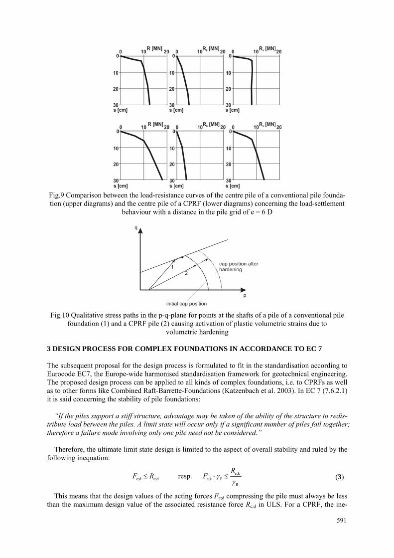
Fig.9 Comparison between the load-resistance curves of the centre pile of a conventional pile founda-tion (upper diagrams) and the centre pile of a CPRF (lower diagrams) concerning the load-settlement
behaviour with a distance in the pile grid of e = 6 D
p
q
initial cap position
cap position afterhardening
1
2
Fig.10 Qualitative stress paths in the p-q-plane for points at the shafts of a pile of a conventional pile
foundation (1) and a CPRF pile (2) causing activation of plastic volumetric strains due to volumetric hardening
3 DESIGN PROCESS FOR COMPLEX FOUNDATIONS IN ACCORDANCE TO EC 7 The subsequent proposal for the design process is formulated to fit in the standardisation according to Eurocode EC7, the Europe-wide harmonised standardisation framework for geotechnical engineering. The proposed design process can be applied to all kinds of complex foundations, i.e. to CPRFs as well as to other forms like Combined Raft-Barrette-Foundations (Katzenbach et al. 2003). In EC 7 (7.6.2.1) it is said concerning the stability of pile foundations:
“If the piles support a stiff structure, advantage may be taken of the ability of the structure to redis-
tribute load between the piles. A limit state will occur only if a significant number of piles fail together; therefore a failure mode involving only one pile need not be considered.”
Therefore, the ultimate limit state design is limited to the aspect of overall stability and ruled by the following inequation:
c;d c;d≤F R resp. c;kc;k F
R
RF γ
γ⋅ ≤ (3)
This means that the design values of the acting forces Fc;d compressing the pile must always be less than the maximum design value of the associated resistance force Rc;d in ULS. For a CPRF, the ine-
591

quation for the proof of the ultimate limit state is formed by the sum of acting forces on the CPRF ΣFc;d and the overall resistance of the CPRF Rtot;d in ULS:
c;d tot;dΣ ≤F R resp. tot;kc;k F
R
RF γ
γΣ ⋅ ≤ (4)
The overall resistance force is – analogously to the pile resistance – dependant on the settlement. The overall resistance force of a CPRF in ULS is defined as that point at which the increasing of the settlement becomes more and more superproportional (fig.11).
OverallResistance
Rtot;k
Settlement
Fig.11 Non-linear system behaviour of the CPRF and determination of the overall resistance in the ULS
As according to EC 7 no numeric determination of the safety level is required, it is sufficient to
safeguard that there will occur no failure before the subsequent resistance force level – derived from the ULS condition (4) – is reached (fig.12):
tot;k c;k F R≥ Σ ⋅ ⋅R F γ γ (5)
Settlement
min Rtot;kFd
OverallResistance
x� �FR
Fig.12 Non-linear system behaviour of the CPRF and determination of the overall resistance
in the ULS
Due to the favourable interactions within a CPRF, a very distinct failure appears quite rarely, in most cases there is a rather smooth increase in the slope of the resistance-settlement-curve. The here displayed methodology is performed on the subsequent example. 592

4 DESIGN EXAMPLE The presented design example exists of a foundation system which has already been presented in sec-tion 2; the numerical model utilises the double symmetry of the foundation system so only a quarter of it is modelled (fig.13). The forces conducted by the superstructure sum up to steady actions of ΣGc;k = 80 MN and variable actions of ΣQc;k=40MN.
Fig.13 Discretisation of the CPRF and the whole model
With this numerical model, a numerical load test by steadily increasing the loads has been per-
formed to generate the characteristic relationship between the settlement of the raft and the total load which is equal to the overall resistance of the CPRF. In fig.14, the evolution of the overall resistance is drawn versus the settlement of the centre of the raft.
0,35
0,30
0,25
0,20
0,15
0,10
0,05
0,000 100 200 300 400 500
Settlement in the middle of the raft [m]
Overall resistance of the CPRF Rtot;k
[MN]
Fig.14 Evolution of the overall resistance of the example CPRF due to the settlement in the middle of
the raft
The evolution of the overall resistance force shows no distinct failure state but rather a continuous decrease of the system stiffness after having left a pseudo-elastic range. This has to be ascribed to the increasing inelastic volumetric deformations which occur due to the hardening of the cap in the consti-tutive model. Due to this fact, no unique resistance force in the Ultimate Limit State (ULS) can be de-ducted and equation (5) will be used. The design value of the total load on the CPRF is computed by
593

c;d c;k G c;k Q=Σ ⋅ + Σ ⋅F G Qγ γ (6)
As the partial safety factors are not uniform in the CEN countries, i.e. the countries where the Euro-code is introduced as standardisation framework, the German factors are chosen according to DIN 1054 (2005):
G
Q
R
=1.35=1.50=1.40
γγ
γ
Applying these safety factors on equation (6) we receive
c;d c;k G c;k Q= =80MN 1.35 40MN 1.50=168MNF G Qγ γΣ ⋅ + Σ ⋅ × + × (7)
According to equation (5) the result of equation (7) is multiplied by the safety factor for the overall resistance and applied:
c;d R =168MN 1.4=235MNF γ⋅ × (8)
Regarding fig.14, it can be seen that up to this loading no failure occurs. Thus, the stability of the foundation has been proved. With the same numerical load test, the investigations concerning Service-ability Limit State (SLS) can be performed because it bears the advantage of a physically orientated computation model. 5 SUMMARY AND PROSPECT It has been shown that at a complex foundation like a CPRF several effects arise effects of the Soil-Structure Interaction which are favourable or the stability and the deformation behaviour of these foundations. Such a computational model can only be a three-dimensional one, based on continuum mechanics and comprising an adequate constitutive description, like the Finite Element Method (FEM).
Moreover, it has been shown that such numerical methods are capable of acting as a reliable tool for the proof of safety in the Ultimate Limit State (ULS) for complex foundations because they can map the relevant interactions. Thus, a concept for a design process for complex foundations based on nu-merical methods and conform to EC 7 is introduced.
The application of a computational model capable of comprehending the presented interactions and a fitting design concept permits an economically more effective foundation concept compared to con-ventional design processes, e.g. for conventional piles. REFERENCES Amann, P. (1975) Über den Einfluss des Verformungsverhaltens des Frankfurter Tons auf die Tiefenwirkung eines Hochhauses und die Form der Setzungsmuld. Mitteilungen des Institutes und der Versuchsanstalt für Geotechnik der Technischen Universität Darmstadt, Heft 15
Burland, J.B., Broms, B.B., De Mello, V.F.B. (1977) Behaviour of foundations and structures. Proc. 9th International Conference on Soil Mechanics and Foundation Engineering, Tokyo, 495-546
CEN (2004). Eurocode 7: Geotechnical design
Chen W.F., Mizuno E. (1990) Nonlinear analysis in soil mechanics: Theory and implementation. De-velopments in Geotechnical Engineering 53, Elsevier, Amsterdam.
Cooke, R.W., Bryde-Smith, D.W., Gooch, M.N., Sillet, D.F. (1981) Some observations of the founda-tion loading and settlement of a multi-storey building on a piled raft foundation in London Clay. Pro-ceedings ICE 107, Part I, S. 433-460, London
594

Cooke, R. W. (1986) Piled raft foundations on stiff clays – a contribution to design philosophy. Géotechnique 36, No. 2, S. 169-203, 1986
DIN 1054 (2005) Subsoil – Verification of the safety of earthworks and foundations. German Standard, 2005
Drucker D.C., Prager W. (1952) Soil mechanics and plastic analysis or limit design. Quarterly of Ap-plied Mathematics, Vol. X, 157-165.
Hanisch, J.; Katzenbach, R.; König, G. (2002) Kombinierte Pfahl-Plattengründungen. Ernst & Sohn, Berlin.
Holzhäuser, J. (1998) Experimentelle und numerische Untersuchungen zum Tragverhalten von Pfahlgründungen im Fels. Mitteilungen des Institutes und der Versuchsanstalt für Geotechnik der Technischen Universität Darmstadt, Heft 42
Hooper, J.A. (1973) Observations on the behaviour of a piled raft foundation in London clay. Pro-ceeding of Institution of Civil Engineers, Vol.55, No.2,pp. 855-877 (1973).
Hooper, J.A. (1979) Review of behaviour of piled raft foundation. CIRIA, report No 83
Katzenbach, R., Quick, H., Arslan, U., Gutwald, J., Holzhäuser, J. (1996) Soil-structure-interaction of the 300 m high Commerzbank tower in Frankfurt am Main - measurements and numerical studies. Proc. XIV ICSMFE, Hamburg, Vol. 2, S. 1081-1084
Katzenbach, R., Reul, O. (1997) Design and performance of piled rafts. Proc. 14th ICSMFE, Hamburg, Vol. 4, 2253-2256, Rotterdam, Balkema
Katzenbach, R., Moormann, C. (1999) Geotechnical field measurements applied to a 240 m high office tower constructed by top/down methods in Frankfurt Clay. Proc. 5th Int. Symp. on Field Measurements in Geomech. FMGM99, 1st -3th December 1999, Singapore, Balkema, Rotterdam, 41-99
Katzenbach, R., Bachmann, G., Ittershagen, M. (2003) Cost optimised foundation methods for high rise buildings on soft soils. 3rd China Urban Housing Conference, Hong Kong, 3rd-5th July 2003
Katzenbach, R., Bachmann, G., Gutberlet, C. (2005) The importance of measurements for evaluating numerical analyses of foundations of high-rise buildings. Proceedings 11th International Conference of the International Association of Computer Methods and Advances in Geomechanics (IACMAG), S. 695-707, Turin, Italien, 19-24.06.2005
Love, J.P. (2003) Use of settlement reducing piles to support a raft structure. Proceedings of the Insti-tution of Civil Engineers 156, 177-181
Phung Duc Long (1993) Footings with settlement-reducing piles in non-cohesive soil. Swedish Geo-technical Institute, 1993
Ranganatham, B. V., Kaniraj, S. R. (1978) Settlement of model pile foundations in sand. Indian Geo-technical Journal 8, No. 1, S. 1-26
Randolph, M.F. (1994) Design methods for pile groups and piled rafts. XIIIth International Conference on Soil Mechanics and Foundation Engineering, 1994, Vol. 4, 61-82, New Delhi, India.
Reul, O. (2000) In-situ-Messungen und numerische Studien zum Tragverhalten der Kombinierten Pfahl-Plattengründung. Mitteilungen des Institutes und der Versuchsanstalt für Geotechnik der Technischen Universität Darmstadt, Heft 53, 2000
595

Smoltzcyk, U., Vogt, N. (2005) Entwurf, Berechnung und Bemessung in der Geotechnik - Teil 1: Allgemeine Regeln - Kommentar zur DIN EN 1997-1: Eurocode 7 (German Comment on EC 7)
Sommer, H., Wittmann, P., Ripper, P. (1985) Piled raft foundation of a tall building in Frankfurt clay. Proc. 11th iICSMFE, San Francisco Vol. 4m 2253-2257, Rotterdam, Balkema
Vesic, A. S. (1969) Experiments with instrumented pile groups in sand. Proc. Performance of Deep Foundations, ASTM, STP 444, S. 177-222, 1969
596