s.m.a.r.t. control board (scb) installation instructions
TRANSCRIPT
S.M.A.R.T. CONTROL
BOARD (SCB)
INSTALLATION
INSTRUCTIONS
BULLETIN 30-039.003

TABLE OF CONTENTS
DESIGN & SPECIFICATIONS .........................................................................................................3
GENERAL .................................................................................................................................3
SCOPE .......................................................................................................................................3
FEATURES ...............................................................................................................................4
SWITCHES................................................................................................................................5
JUMPERS ..................................................................................................................................7
LED LIGHTS.............................................................................................................................8
LOCATION AND MOUNTING ...............................................................................................8
BOARD TERMINALS ..............................................................................................................9
WIRING ...................................................................................................................................12
Certified to UL Standard 1995Conforms to CAN/CSA Standard C22.2 NO. 236
Unico products comply with the Europeanregulations that guarantee product safety.
Bulletin 30-039.003
Copyright © 2017 Unico Inc. Page 3
DESIGN & SPECIFICATIONS
General
The information on the following pages is to provide the
installer the necessary information to properly install the
Unico software managed air flow rate and temperature
S.M.A.R.T. control board (SCB). The SCB control board
is available as part of the blower assembly or as part of
retrofit kit that includes the motor and blower wheel.
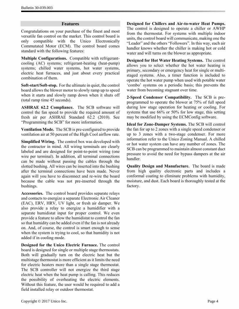
Part no.* Description
U1218L1-EC* Fan Coil Unit with SCB control, where ‘ * ’ is voltage M2430BL1-EC* Blower Module, 2430, with SCB and EC motor
M3036BL1-EC* Blower Module, 3036, with SCB and EC motor
M3642BL1-EC* Blower Module, 3642, with SCB and EC motor M4860BL1-EC* Blower Module, 4860, with SCB and EC motor ‘x’ indicates voltage (1=120V, 2=240V)
* There may be additional characters at the end for other options.
Upgrade Kits (for units made after 2003),
includes motor, wheel, and control box
A01543-K22 Upgrade Kit, EC2 (240V), 2430 A01543-K23 Upgrade Kit, EC2 (240V), 3642
A01543-K24 Upgrade Kit, EC2 (240V), 4860
Optional Accessories/Replacement Parts
A00175-G07 Control Box Assy with SCB, 240V A00175-G10 Control Box Assy with SCB, 120V
A01426-002 Motor, EC, 1800RPM, 1/2 hp
A01426-003 Motor, EC, 1800 RPM, 1 hp
A01469-G03 Control Board, S.M.A.R.T. (for all blower models)
A01470-G01 Control Board, USB (laptop communication)
A01472-G01 Wire Harness, EC Motor, 240V
A01472-G02 Wire Harness, EC Motor, 120V A01473-G01 Wire Harness, SCB/USB to ECM
A01474-G01 Wire Harness, SCB to USB
A01722-005 Chip, EEPROM (latest version upgrade) A01002-013 Fuse, Slow-blow, 2AG, 3A
A01412-001 Fuse, MINI-Blade, 2A
A00057-G04 Transformer, 208/230V-24V, 50VA A00057-G05 Transformer, 100/120V-24V, 50VA
A01525-G01 Cable, Extension, ECM (CE), 59 inch (1.5 m) A01525-G02 Cable, Extension, ECM (CE), 98 inch (2.5 m)
1 S.M.A.R.T. = Software Managed Air Rate and Temperature
Scope
The S.M.A.R.T. control board provides system control for
Unico air handlers with EC motors. The control box
comes with software (ECMConfig) and a USB cable to
connect to a personal computer, which allows the user to
set the precise airflow for each Mode of operation.
Windows XP, 7, or 8 operating system is generally
required; Use of a Windows emulator for Mac systems is
possible, but not recommended. The ECMConfig
software can also be downloaded from:
http://tech.unicosystem.com/ .
This manual includes the instructions for the SCB board
and the applicable firmware version as shown in Table 1.
The firmware version can be checked on boards with
version 3.19 and later by going to Help|About in
ECMConfig version 4.5 and newer.
Table 1. Control Board part number
Board P/N Compatible Blower Models Firmware
Version*
A01469-G01 1218, 2430, 3642, 4860 BV
A01469-G02 1218, 2430, 3036, 4860 BV3036
A01469-G03 1218, 2430, 3036, 3642, 4860 3_19
* Actual firmware may be later revision
NOTE: P/N A01469-G03 replaces both A01469-G01 and
A01469-G02. For clarity, and to support older
installations, this manual will sometimes include
instructions for the older, discontinued boards.
Bulletin 30-039.003
Copyright © 2017 Unico Inc. Page 4
Features
Congratulations on your purchase of the finest and most
versatile fan control on the market. This control board is
only compatible with the Unico Electronically
Commutated Motor (ECM). The control board comes
standard with the following features:
Multiple Configurations. Compatible with refrigerant-
cooling (AC) systems; refrigerant-heating (heat-pump)
systems; chilled water systems, hot water systems,
electric heat furnaces, and just about every practical
combination of them.
Soft-start/Soft-stop. For the ultimate in quiet, the control
board allows the blower motor to slowly ramp up to speed
when it starts and slowly ramp down when it shuts off
(total ramp time 45 seconds).
ASHRAE 62.2 Compliance. The SCB software will
control the fan speed to provide the required amount of
fresh air per ASHRAE Standard 62.2 (2010). See
“Programming the SCB” for more information.
Ventilation Mode. The SCB is pre-configured to provide
ventilation air at 50 percent of the High Cool airflow rate.
Simplified Wiring. The control box was developed with
the contractor in mind. All wiring terminals are clearly
labeled and are designed for point-to-point wiring (one
wire per terminal). In addition, all terminal connections
can be made without passing the cables through the
slotted bushing. All wires can be inserted into the bushing
after the terminal connections have been made. Never
again will you have to disconnect and re-wire the board
because the cable was not pre-inserted through the
bushings.
Accessories. The control board provides separate relays
and contacts to energize a separate Electronic Air Cleaner
(EAC), ERV, HRV, UV light, or fresh air damper. We
also provide a relay to energize a humidifier with a
separate humidistat input for proper control. We even
provide a feature to allow the humidistat to control the fan
so that humidity can be added even if the fan is not already
on. And, of course, the control is smart enough to sense
when the system is trying to cool, so that humidity is not
added if in cooling mode.
Designed for the Unico Electric Furnace. The control
board is designed for single or multiple stage thermostats.
Both will gradually turn on the electric heat but the
multistage thermostat is more efficient as it limits the need
for electric heaters more than a single stage thermostat.
The SCB controller will not energize the third stage
electric heat when the heat pump is calling. This reduces
the possibility of overheating the electric elements.
Without this feature, the user would be required to add a
field installed relay or outdoor thermostat.
Designed for Chillers and Air-to-water Heat Pumps. The control is designed to operate a chiller or AWHP
from the thermostat. For systems with multiple indoor
units, the control board will communicate, making one the
“Leader” and the others “Followers”. In this way, each air
handler knows whether the chiller is making hot or cold
water and will turns on the blower as appropriate.
Designed for Hot Water Heating Systems. The control
allows you to select whether the hot water heating is
primary, secondary or emergency heat for single or multi-
staged systems. Also, a timer function is included to
operate the hot water pump when used with potable water
‘combo’ systems on a periodic basis; this prevents the
water from becoming stagnant over time.
2-Speed Condenser Compatibility. The SCB is pre-
programmed to operate the blower at 75% of full speed
during low stage operation for heating or cooling. For
systems that use 66% or 50% for low stage, this setting
may be modified by using the ECMConfig software.
Ideal for Zone-Damper Systems. The SCB will control
the fan for up to 2 zones with a single speed condenser or
up to 3 zones with a two-stage condenser. For more
information refer to the Unico Zoning Manual. A chilled
or hot water system can have any number of zones. The
SCB can be programmed to maintain almost constant duct
pressure to avoid the need for bypass dampers at the air
handler.
Quality Design and Manufacture. The board is made
from high quality electronic parts and includes a
conformal coating to eliminate problems with humidity,
moisture, and dust. Each board is thoroughly tested at the
factory.

Bulletin 30-039.003
Copyright © 2017 Unico Inc. Page 5
Switches
There are nine manual function switches on the SCB. All
of the switches can be moved with the unit operating
although changes to CFM, MOD, and AUX will not take
effect until the board is turned off and then back on.
Changing these switches and then cycling the power will
erase any custom settings, so do not adjust them unless
necessary.
Figure 2a. Switch and LED layout. SCB boards
manufactured prior to August 2014 (Part
numbers A01469-G01 and A01469-G02)
Figure 2b. Switch and LED layout. SCB boards
manufactured after August 2014 (Part
number A01469-G03)
CFM (High|Low, factory default = Hi). This switch sets
the High Cool airflow rate in accordance with Table 2.
The airflow for all other modes of operation are set to a
percentage of the High Cool airflow as shown in Table 3.
All airflows can be customized using the ECMConfig
program. Moving this switch and powering the board off
and on will erase any customized settings.
Table 2. Default high-cool airflow rate (CFM switch)
Blower
Model
CFM Switch Setting
Low High
CFM L/s CFM L/s
1218 300 141 400 189
2430 500 236 625 295
3036 625 295 750 354
3642 750 354 875 413
4860 1000 472 1250 590 Table 3. Airflow defaults (for all modes)
Operating Mode Percentage of High Cool
Airflow
High Cool (Y2) 100%
Low Cool (Y1) 75%
High Heat (W2) 100%
Low Heat (W1) 75%
Emergency Heat (E) 100%
Fan Recirculation (G) 50%
MOD (1 | 0, no factory default). The control board must
be set for the correct blower model. Control board
A01469-G03 uses both the MOD and the AUX switches
as shown in Table 4a. Control board A01469-G01 and
A01469-G02 uses the MODEL switch as shown in Table
4b.
Table 4a. Model selection for control board A01469-
G03
Blower Model MOD AUX
1218 1 0
2430 0 0
3036 1 1
3642 1 0
4860 0 0
Table 4b. Model selection for control board A01469-
G01 and A01469-G02
Blower Model MODEL switch position
A01469-G01 A01469-G02
1218 1218/
3642
1218/
4860
2430 2430/
4860
2430/
4860
3036 n/a 1218/
3642
3642 1218/
3642 n/a
4860 2430/
4860
2430/
4860
NOTE: For all control boards, changing the MOD
switch and cycling the power will reset the program
settings to the factory default.
AUX (1 | 0, factory default=0). Use this switch along
with the MOD switch to set the blower model as shown
in Table 4.
NOTE: For A01469-G03, changing the AUX switch and cycling the power will reset the SCB to the factory default. For A01469-G01 and A01469-G02, the AUX switch will not reset the program settings.
Capacity
Flash=PCBCtrl
Hi Lo
12183642
24304860
Model
Power
FanHeat
BoilerPriority E
Chiller Leader
OnPotableWater
Primary
Follower
Off
Air Cycle
HumSpd
Aux
Hi
RevValve
O B
Cut if ReversingValve Uses B
Lo
Off
Off
Solid = ovrspd
The Unico SystemR
= LED (light)= Switch
Flash = Comm. errorLoE
Hi
Off
CFM
Aux
Lo
0
RevValve
0
O
Mod 1
B
BoilerPriority
Cut wire IfRev Valve =B
Chiller Leader
Power
PotableWater
Heat
On
Elect.htr Enable
Off
RPMLimitCFMx100CFMx 50
Follower
A01588-003
Primary
Air Cycle
HumSpd Hi
Model
12182430303636424860
400625750825
1250
(Mod)
10110
(Aux)
00100
CFM(Hi Lo)*
*TO RESET, change
Mod, Aux, or CFM
1
3005006257501000
= LED (light)= Switch
Bulletin 30-039.003
Copyright © 2017 Unico Inc. Page 6
For control board part numbers A01469-G01 and
A01469-G02 the AUX switch is used to change the
behavior of the PCBctl LED. Refer to Table 7 for more
information. For that board, the OFF position is “Normal”
and will display error codes. The ON position is “Check
CFM” and will display the current blower airflow. These
functions were combined in A01469-G03 and are always
active.
POTABLE WATER (ON|OFF, factory default=OFF)
For ‘combo’ systems, where potable water is circulated
through the hot water heating coil, it is necessary to ensure
that the water is never stagnant in the coil. The switch will
activate a timer so that the HotW relay will energize a
pump to circulate water once per day for 5 minutes
regardless.
AIR CYCLE (ON|OFF, factory default=OFF) Used to
periodically circulate air through the ducts to reduce the
chance of moisture build up in the winter months. By
default, the fan will run on Fan speed for 10 minutes every
8 hours even if there is no thermostat demand for heat or
cool or fan. This timing, along with ASHRAE 62.2
compliant modes of operation, can be configured using
the ECMConfig interface.
HUM SPD (HIGH|LOW, factory default = HIGH)
Allows a separate humidistat to control the fan operation
under certain conditions. A humidistat with a dry contact
input is require to energize the fan and close the dry
contact relay on the HumVlv terminals.
If the unit is not in cooling or heating (when it is off) the
HumStat will turn on the fan to the speed set by the
switch. In the default condition (Humidistat
Control=HIGH) the relay will energize the fan at the high-
heat speed. If the Humidistat Control switch is moved to
the LOW position, the blower will run at the FAN airflow
rate.
REV VALVE (B|O, factory default = O). This switch is
set to O (meaning the reversing valve is energized in
cooling mode) regardless of position unless the jumper
wire is cut. If the reversing valve is energized on heating,
the heat pump jumper wire (see next section) must be cut
and this switch moved to the B position.
CAUTION
To prevent the potential of coil frosting for
‘cooling-only’ systems, be sure the jumper
across R and O-b is in place. If not, the AFS
may not work properly.
Note: if the jumper wire is cut, make sure the
reversing valve switch on the board is in the
O position.
The control board knows whether the system is heating or
cooling by comparing the O-b thermostat signal to the
position of the REV VALVE switch. Refer to the notes in
Table 5.
CHILLER (Leader|Follower, default=Leader). This
switch controls the operation of both the chiller relay
(ColdW) and the boiler relay (HotW). If the switch is in
the ‘leader’ position, the ColdW relay will energize with
any call to Y1 or Y2.
NOTE: For cooling-only chillers, always set the
chiller to “leader”. The “follower” function is only
necessary for heat pump chillers.
For heat pump chiller systems, if there is more than one
air handler connected to the system, we recommend that
all air handlers be set to the same mode (either heating or
cooling). Otherwise, the chiller could frequently switch
between heating and cooling. This will not damage the
equipment but is energy wasteful because the chiller must
heat and cool a large volume of water every time it
changes mode.
To prevent this switching behavior, use a manual switch
to set the mode by sending an O-b signal to all air
handlers, which must all be set as a “follower”.
It is possible to automate this by setting one of the air
handlers as “leader” and all others as “followers”. This is
not completely fool-proof though. The system can still
switch back and forth if the leader is not calling for heat
or cool (the unit appears to be off so there is no O-b
signal). In this case, the “leader” air handler must use a
heat pump thermostat. Always use a heat-cool thermostat
when in “follower” mode.
By utilizing a manual leader switch or leader air handler,
the leading air handler is the master controller and
determines the temperature of the water by utilizing the
O-b signal from the heat pump thermostat. Subordinate
air handlers are followers and will only energize the
blowers if the water is the correct temperature.
As recommended above, it is best to simulate the leader
function by installing a manual switch create the O-b
signal; this makes all the air handlers followers.
Bulletin 30-039.003
Copyright © 2017 Unico Inc. Page 7
NOTE: When setting the unit to “follower”, the W1
and W2 inputs will not energize the HotW relay even
if the BOILER switch is set to PRIMARY because
the system assumes that the system is a heat pump
chiller.
Table 5. When the ColdW (CW) and HotW (HW) relays
energize Switch Position Thermostat Input
Chiller Boiler Y1 Y2 W1 W2 E
Leader Primary CW CW HW HW -
Emergency CW CW - - HW
Follower* Primary CW CW CW CW -
Emergency CW CW CW CW HW
* ColdW will energize if the system is in the
correct mode, i.e. heating if W1 or W2, or
cooling if Y1 or Y2. If not in correct mode, only the fan will energize.
O-b
input
Rev. Valve Switch
O B
YES Cooling Heating
NO Heating Cooling
BOILER PRIORITY (Emergency|Primary, factory
default = Primary). This switch controls when the HotW
relay is energized as shown in table 5.
Reset Factory Defaults. It is possible to reset the airflow
settings to their factory defaults at any time. This will
erase any custom settings created with the software,
therefore only do this if you do not have a computer
connected and are unsure if the airflow has been modified.
To reset the airflow to the default, change the postion of
one of the following switches, then turn the power off and
then back on (cycle the power).
Table 6. RESET switches (if power is cycled)
Part No. Switches
A01469-G01 CAPACITY, MODEL
A01469-G02
A01469-G03 CAPACITY, MOD, AUX
If you change the position of the switch with the power
on, the A01469-G03 board will flash an error code
indicating that a reset will happen if the power is cycled.
If you accidently change a switch, simply switch it back
again before you cycle the power. Then turn off the power
to the SCB and then turn it on. The board will check the
switch position each time it is first powered on. If the
positions have been changed since the last time the board
was on, the internal airflow values will be reset to the
factory default.
Changing the postion of these switches when the unit is
powered on or while it is off will have no effect unless the
positions are different at the time it is turned on compared
to the last time it was turned on.
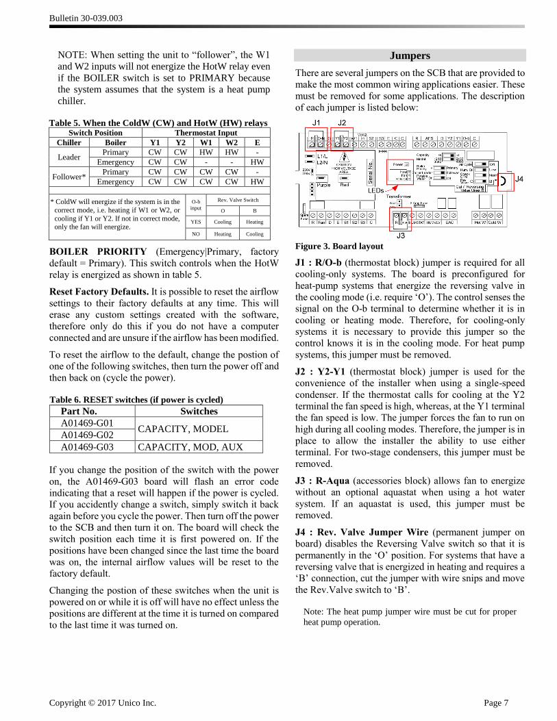
Jumpers
There are several jumpers on the SCB that are provided to
make the most common wiring applications easier. These
must be removed for some applications. The description
of each jumper is listed below:
Figure 3. Board layout
J1 : R/O-b (thermostat block) jumper is required for all
cooling-only systems. The board is preconfigured for
heat-pump systems that energize the reversing valve in
the cooling mode (i.e. require ‘O’). The control senses the
signal on the O-b terminal to determine whether it is in
cooling or heating mode. Therefore, for cooling-only
systems it is necessary to provide this jumper so the
control knows it is in the cooling mode. For heat pump
systems, this jumper must be removed.
J2 : Y2-Y1 (thermostat block) jumper is used for the
convenience of the installer when using a single-speed
condenser. If the thermostat calls for cooling at the Y2
terminal the fan speed is high, whereas, at the Y1 terminal
the fan speed is low. The jumper forces the fan to run on
high during all cooling modes. Therefore, the jumper is in
place to allow the installer the ability to use either
terminal. For two-stage condensers, this jumper must be
removed.
J3 : R-Aqua (accessories block) allows fan to energize
without an optional aquastat when using a hot water
system. If an aquastat is used, this jumper must be
removed.
J4 : Rev. Valve Jumper Wire (permanent jumper on
board) disables the Reversing Valve switch so that it is
permanently in the ‘O’ position. For systems that have a
reversing valve that is energized in heating and requires a
‘B’ connection, cut the jumper with wire snips and move
the Rev.Valve switch to ‘B’.
Note: The heat pump jumper wire must be cut for proper
heat pump operation.
Bulletin 30-039.003
Copyright © 2017 Unico Inc. Page 8
LED Lights
There are four LEDs on the SCB board. Their locations
are shown in Figure 3. Their labels are shown in Figure 2,
and depend on control board model. Their functions are
described below. For control board A01469-G03 use
Table 7a. For control boards A01469-G01 and A01469-
G02, use table 7b. For control boards A01469-G01 and
A01469-G02, the PCBctl LED depends on the position of
the AUX switch as follows:
Table 7a. LEDs (A01469-G03) LED State Meaning
Power (green)
“heart beat”
Off No power. Check voltage.
Flashing Board is functioning properly.
Solid
The control board program has stopped.
Turn power off and on to reset. Replace board if unable to reset.
Heat
(red)
Off System is not in heating mode
Flashing
(Long ON flashes)
Pending program reset. The MOD, CFM, or
AUX switch has changed.
Flashing
(Short ON flashes)
No communication to the motor. Check cables and power to motor.
Solid System is in the heating or reheat
(simultaneous cooling and heating) mode.
Elect. Htr.
Enable
(green) [Fan]*
Off
No call for fan or airflow less than 75% of
programmed value; electric heater enable relay is off.
Solid Fan has reached 75% of programmed
airflow; electric heater enabled relay is on.
Flash
‘Check
Airflow’ (red)
[PCBctl]
Off Fan is not running.
Long flash 100 CFM
Short Flash 50 CFM (last flash in a sequence)
Extra-long flash
(1 sec)
Motor is at maximum RPM limit and cannot
achieve desired air flow (flashes between
airflow sequence)
Solid (Reserved for future use)
*[] indicates the name of the LED for A01469-G01 and A01469-G02.
Table 7b. LEDs (A01469-G01 and A01469-G02)
LED State Meaning
PCBctl (red)
Normal Mode
(Aux switch
= OFF)
Off Normal operation
Blinking Air Cycle mode, or in the Potable Water
mode.
Solid
Fan is at max RPM and is unable to achieve
the programmed airflow.
This normally indicates a restrictive duct system unless it is zoned system where the
user has changed the maximum RPM.
PCBctl
(red)
Check CFM
Mode (Aux switch
= ON)
Long flash 100 CFM for each long flash
Short flash 50 CFM (last flash in a sequence)
The USB board has two LED lights.
Table 8. USB board LEDs
LED 1
(green) Flashing
SCB sending message to ECMConfig
program
LED 2
(red) Flashing
ECMConfig program sending message to
SCB
Location and Mounting
Before installing the SCB, inspect thoroughly for
shipping damages. Notify carrier immediately if there is
any damage.
Figure 4. Control Box Mounting Locations.
The control box can be installed in either one of two
positions on the modular air handler (Figure 4). Choose
the position that allows the best access. The control box
can be mounted remotely using an extension cable, part
number A01525-G01 (5ft) or A01525-G02 (8ft).
CAUTION
THE CONTROL BOX MUST BE
SCREWED TO THE AIR HANDLER OR
REMOTE MOUNTED USING THE
UNICO EXTENSION CABLE TO
PROVIDE PROPER GROUND FOR
THE MOTOR.
The knock-out on top/front of the air handler must be
removed to allow the motor cable connector to extend into
the air handler space.
Control BoxLocation
Blower Module
Plenum
Bulletin 30-039.003
Copyright © 2017 Unico Inc. Page 9
Board Terminals
The following tables describe in detail the function of each terminal on the control board.
Table 9. Thermostat Terminal Block Description
Inp
uts
R Power out. 24VAC power signal.
O-b Reversing valve input from thermostat. Can be either O or B, depending on the
requirements of the outdoor unit.
G Fan input. Blower will operate at fan speed unless there is a call on Y1, Y2, W1, W2 or
E. Refer to Tables 2 and 3 for default blower airflow settings.
Y2 High Cool input. Will energize the blower at High Cool airflow and pass a signal to Y2
on the condenser terminal block.
Y1 Low Cool input. Will energize the blower at Low Cool airflow and pass a signal to Y1
on the condenser terminal block.
W1 Heat input (first stage of two-stage heat). Electric heater will not turn on with this
signal. Blower will run at Low Heat airflow rate.
W/
W2/
S1
Heat input (single stage heat, second stage of two-stage heat, or first stage electric heat)
Powers S1 electric heat terminal (direct connection). Electric heater will energize when
fan is at full speed (not ramping). Blower will operate at High Heat speed.
S2 Heat input (third stage heat). Connects to S2 on the thermostat terminal block. Powers
S2 on the electric heat terminal block (direct connection). Will not power the blower.
S3
Heat input (third stage). Connects through a NC relay to S3 on the thermostat terminal
block. Powers S3 electric heat terminal if operating in heat pump mode (signal present
at Y2 or Y1). Will not power the blower.
E
Emergency heat input. Powers E on the electric heat terminal block (direct connection
from Thermostat Terminal Block terminal E input). Blower will operate at the
Emergency airflow rate.
C Common. Used to power the thermostat, or an external relay, if required.
Note: Factory ships with jumper across Y2 and Y1, and a jumper across R and O-b.
The Y2-Y1 jumper must be removed for two-speed condensers. The jumper is only a convenience so that either terminal may be
used for single-speed condensers.
The R-Ob jumper must be removed for heat pump systems. The Rev.Valve switch must be set properly.
Bulletin 30-039.003
Copyright © 2017 Unico Inc. Page 10
Table 10. Condenser Terminal Block Description
R Power out. 24VAC power signal.
Dry
Co
nta
ct
Inp
ut
(Rate
d
24
VA
C,
2 a
mp
)
AFS
Anti-frost switch input. The AFS is mounted on all refrigerant coils. When the AFS is closed
and in cooling mode, the control will allow the Y1 or Y2 condenser terminals to be energized.
If the AFS switch opens, the condensers will stop although the indoor blower will continue to
operate. The AFS will not affect operation of the condensers if in the heating mode. The AFS
switch will open at 34°F±3°F (1°C±1.6°C) and close at 60°F±3°F (15.5°C±2.8°C). The AFS
contacts are normally open and close when the R-Ob jumper is removed for heat pump
application.
Inp
ut
(24
VA
C)
D
Defrost input from the outdoor unit. Powers D on the electric heat terminal block (direct
connection). The D terminal must be connected for all heat pumps. This prevents AFS
nuisance trips from occurring if the outdoor unit control board energizes O-b during defrost.
Ou
tpu
ts
(24 V
AC
)
Y1 Cool output. Will energize single-speed condenser or the first-stage of a two-stage condenser.
Y2 Cool output. Will energize the second-stage of a two-stage condenser.
O-b Reversing valve output. Can be configured as either O or B, depending on the requirements
of the outdoor unit.
C Common. Used to power the relays and controls in the condenser.
Table 11. Accessories Terminal Block Description
R Power out. 24VAC power signal.
Dry
Con
tact
Inp
ut Aqua
Aquastat input. Allows the option of using an aqua-stat to reduce the time it takes for the air
to become hot when heating. The fan will not energize until the aquastat is satisfied.
HumStat Humidistat input. The HumVlv contacts will close whenever the humidistat calls for
humidity and the unit is not in cooling. The fan will come on if necessary.
Dry
Con
tact
Ou
tpu
t (1
20
VA
C,
3
am
p)
HumVlv Used to turn on humidifier (contacts close) when there is a call from the Humidistat.
EAC
Used to energize an electronic air cleaner (EAC), ERV, HRV, or UV-light (contacts close
when fan is on).
Can also be software-configured to control a fresh air damper (contacts close as required by
software algorithms.)
Dry
Co
nta
ct
Ou
tpu
t (2
50
VA
C,
5 A
mp
s)
HotW Used to energize either a boiler, valve, or pump. Contacts will close based on the inputs
shown in Table 6.
ColdW Used to energize a chiller, valve, or pump. Contacts will close based on the inputs shown in
Table 6.
Note: All boards ship from the factory with a jumper across R and Aqua. This jumper must be removed if an aquastat is used.
Bulletin 30-039.003
Copyright © 2017 Unico Inc. Page 11
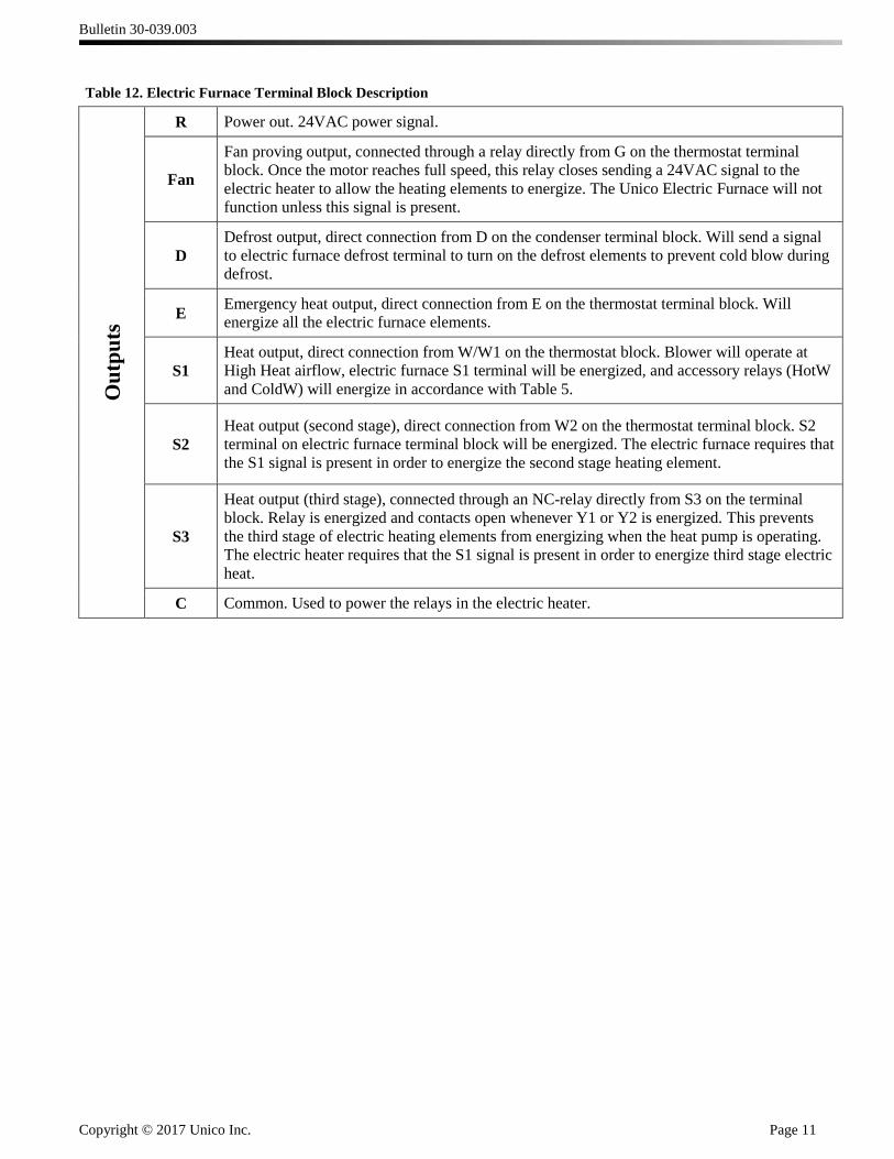
Table 12. Electric Furnace Terminal Block Description
Ou
tpu
ts
R Power out. 24VAC power signal.
Fan
Fan proving output, connected through a relay directly from G on the thermostat terminal
block. Once the motor reaches full speed, this relay closes sending a 24VAC signal to the
electric heater to allow the heating elements to energize. The Unico Electric Furnace will not
function unless this signal is present.
D
Defrost output, direct connection from D on the condenser terminal block. Will send a signal
to electric furnace defrost terminal to turn on the defrost elements to prevent cold blow during
defrost.
E Emergency heat output, direct connection from E on the thermostat terminal block. Will
energize all the electric furnace elements.
S1
Heat output, direct connection from W/W1 on the thermostat block. Blower will operate at
High Heat airflow, electric furnace S1 terminal will be energized, and accessory relays (HotW
and ColdW) will energize in accordance with Table 5.
S2
Heat output (second stage), direct connection from W2 on the thermostat terminal block. S2
terminal on electric furnace terminal block will be energized. The electric furnace requires that
the S1 signal is present in order to energize the second stage heating element.
S3
Heat output (third stage), connected through an NC-relay directly from S3 on the terminal
block. Relay is energized and contacts open whenever Y1 or Y2 is energized. This prevents
the third stage of electric heating elements from energizing when the heat pump is operating.
The electric heater requires that the S1 signal is present in order to energize third stage electric
heat.
C Common. Used to power the relays in the electric heater.

Bulletin 30-039.003
Copyright © 2017 Unico Inc. Page 12
Wiring
WARNING!
DISCONNECT ELECTRICAL SUPPLY
BEFORE WIRING UNIT TO PREVENT
INJURY OR DEATH FROM
ELECTRICAL SHOCK.
All electrical wiring must comply with all local codes and
ordinances. Use a separate power supply with appropriate
amp fuse or breaker and wire gauge for the specified
amperage. Do not wire directly to condenser or add other
equipment to the blower power circuit.
CAUTION
Be sure that the input power voltage
matches the control box to prevent damage
to the equipment.
Once the control box is mounted to the cabinet, the motor
can be connected from inside the air handler. Remove the
appropriate air handler access panel. Connect the motor
connector to the mating end of the control box wiring
harness, pushing firmly to be sure the connector is seated.
Connect the control wiring for the external devices such
as the thermostat, condenser, and electric furnace to the
SCB using the appropriate wiring diagrams as shown
below.
There are several knockouts on the sides of the control
box to bring in the power lines. Use the most convenient
ones to bring in line voltage and ground to the terminal
block as shown in Figure 5.
Figure 5. Terminal block for incoming line voltage
connections.
Figure 6. Power and internal wiring diagram.
Bulletin 30-039.003
Copyright © 2017 Unico Inc. Page 13
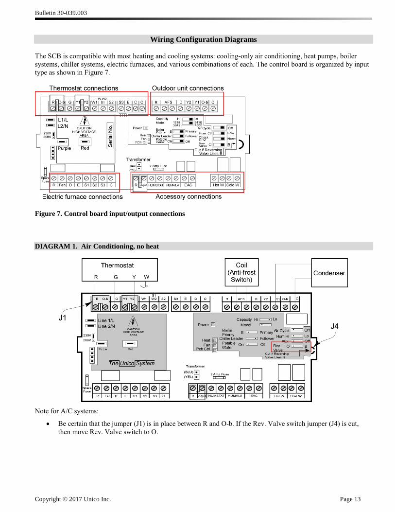
Wiring Configuration Diagrams
The SCB is compatible with most heating and cooling systems: cooling-only air conditioning, heat pumps, boiler
systems, chiller systems, electric furnaces, and various combinations of each. The control board is organized by input
type as shown in Figure 7.
Figure 7. Control board input/output connections
DIAGRAM 1. Air Conditioning, no heat
Note for A/C systems:
Be certain that the jumper (J1) is in place between R and O-b. If the Rev. Valve switch jumper (J4) is cut,
then move Rev. Valve switch to O.

Bulletin 30-039.003
Copyright © 2017 Unico Inc. Page 14
DIAGRAM 2. Heat pump, no secondary heat
Notes for heat pump systems.
Use a heat pump thermostat.
Remove jumper (J1) between R and O-b on the thermostat block.
If the reversing valve is energized in the heating mode, cut the heat pump jumper wire and be sure that the
Reversing Valve switch is in the ‘B’ position. Connect ‘B’ from the thermostat to ‘O-b’ on the thermostat input
terminal block on the board.
If the heat pump reversing valve is energized in the cooling mode (i.e. requires the ‘O’ signal), it is not necessary
to cut the reversing valve jumper wire. However, if the wire is cut, then move the switch to the ‘O’ position and
connect ‘O’ from the thermostat to ‘O-b’ on the thermostat input terminal block on the board.
Note: Most heat pumps use ‘O’.
Bulletin 30-039.003
Copyright © 2017 Unico Inc. Page 15
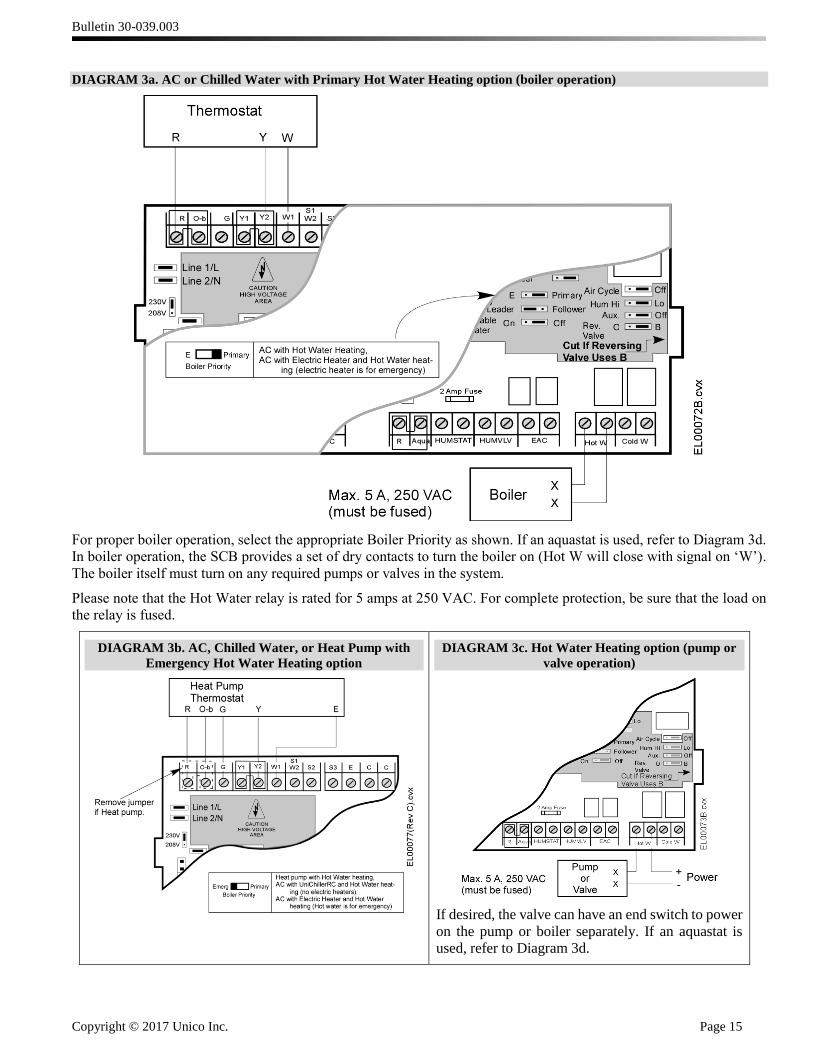
DIAGRAM 3a. AC or Chilled Water with Primary Hot Water Heating option (boiler operation)
For proper boiler operation, select the appropriate Boiler Priority as shown. If an aquastat is used, refer to Diagram 3d.
In boiler operation, the SCB provides a set of dry contacts to turn the boiler on (Hot W will close with signal on ‘W’).
The boiler itself must turn on any required pumps or valves in the system.
Please note that the Hot Water relay is rated for 5 amps at 250 VAC. For complete protection, be sure that the load on
the relay is fused.
DIAGRAM 3b. AC, Chilled Water, or Heat Pump with
Emergency Hot Water Heating option
DIAGRAM 3c. Hot Water Heating option (pump or
valve operation)
If desired, the valve can have an end switch to power
on the pump or boiler separately. If an aquastat is
used, refer to Diagram 3d.
Bulletin 30-039.003
Copyright © 2017 Unico Inc. Page 16
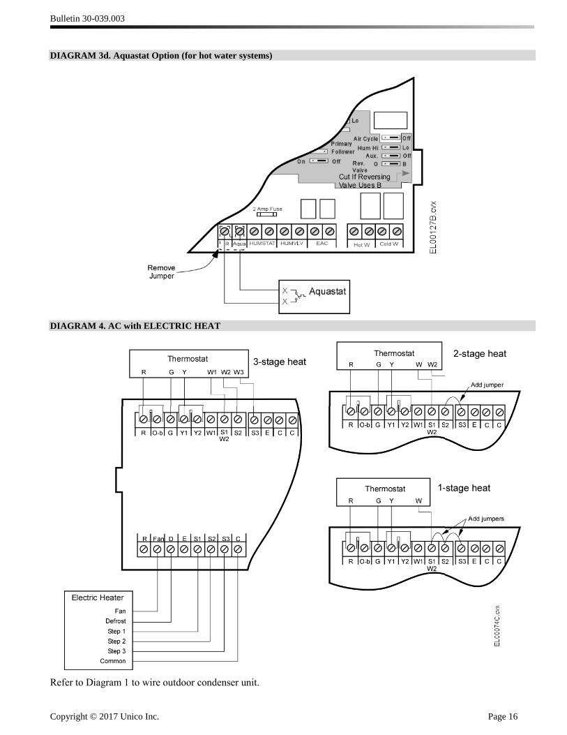
DIAGRAM 3d. Aquastat Option (for hot water systems)
DIAGRAM 4. AC with ELECTRIC HEAT
Refer to Diagram 1 to wire outdoor condenser unit.
Bulletin 30-039.003
Copyright © 2017 Unico Inc. Page 17
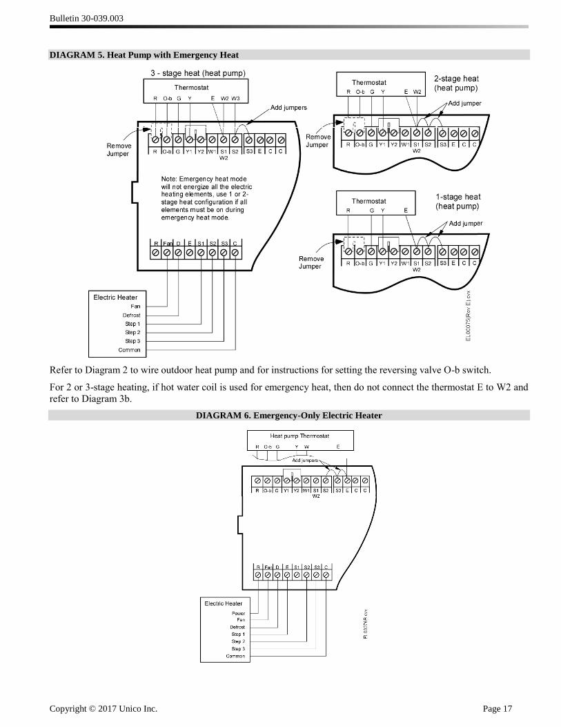
DIAGRAM 5. Heat Pump with Emergency Heat
Refer to Diagram 2 to wire outdoor heat pump and for instructions for setting the reversing valve O-b switch.
For 2 or 3-stage heating, if hot water coil is used for emergency heat, then do not connect the thermostat E to W2 and
refer to Diagram 3b.
DIAGRAM 6. Emergency-Only Electric Heater
Bulletin 30-039.003
Copyright © 2017 Unico Inc. Page 18
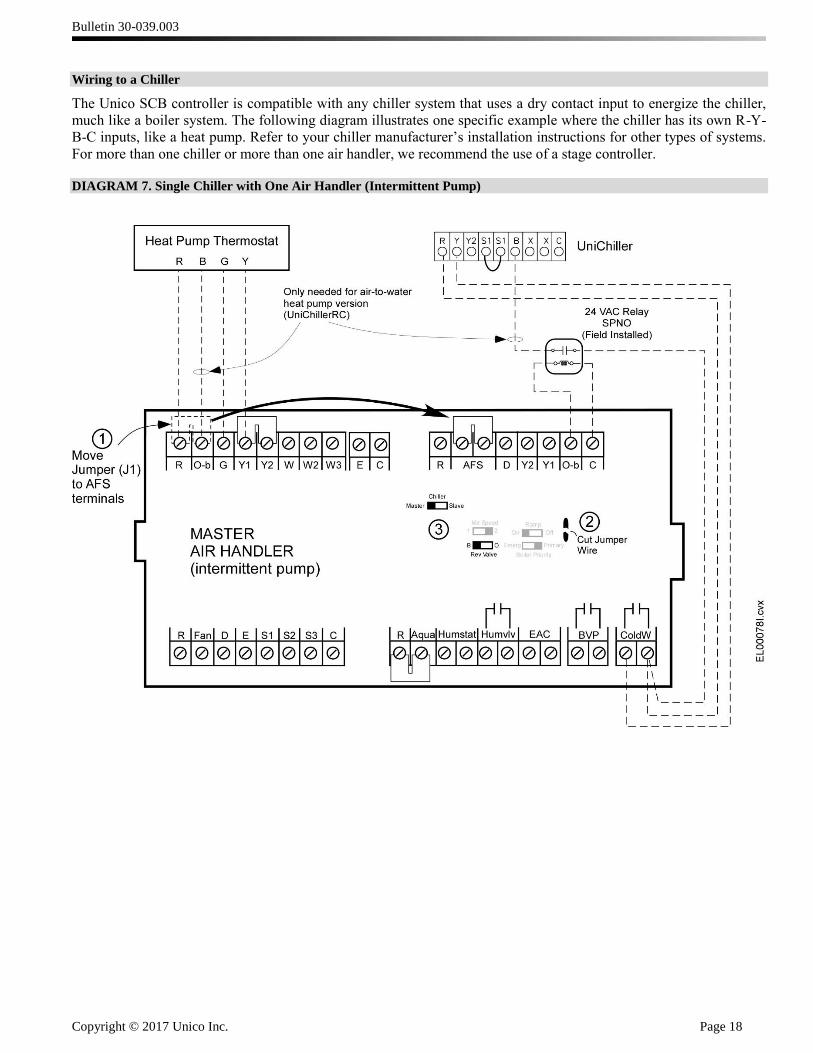
Wiring to a Chiller
The Unico SCB controller is compatible with any chiller system that uses a dry contact input to energize the chiller,
much like a boiler system. The following diagram illustrates one specific example where the chiller has its own R-Y-
B-C inputs, like a heat pump. Refer to your chiller manufacturer’s installation instructions for other types of systems.
For more than one chiller or more than one air handler, we recommend the use of a stage controller.
DIAGRAM 7. Single Chiller with One Air Handler (Intermittent Pump)

Bulletin 30-039.003
Copyright © 2017 Unico Inc. Page 19
DIAGRAM 8. Humidity System
(for line voltage power humidifier or humidifier valve)
(for 24 V power humidifier or humidifier valve)
Set Humidity Control switch (Hum Spd) to proper position. The ‘HI’ position will energize the high cool fan airflow in
response to a call for humidity from the humidistat unless the fan is already operating at high. The Humidity Valve
relay (HumVIv) will then close and turn on the humidifier. If the switch is in the ‘LOW’ position, then the blower will
operate at the Fan airflow rate, and the Humidity Valve relay will close and turn on the humidifier.
DIAGRAM 9. Electronic Air Cleaner (EAC), Recovery Ventilator (ERV or HRV), or UV light connection
(for line voltage EAC or UV light)
(for 24 V power EAC or UV light)
Diagram 9 shows how to connect an ERV, HRV, or EAC that you want to turn on whenever the blower is on. Call
Unico customer service for instructions if the device needs to operate on a predetermined time schedule.
Bulletin 30-039.003
Copyright © 2017 Unico Inc. Page 20
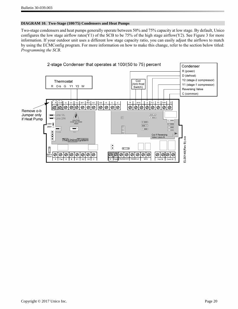
DIAGRAM 10. Two-Stage (100/75) Condensers and Heat Pumps
Two-stage condensers and heat pumps generally operate between 50% and 75% capacity at low stage. By default, Unico
configures the low stage airflow rates(Y1) of the SCB to be 75% of the high stage airflow(Y2). See Figure 3 for more
information. If your outdoor unit uses a different low stage capacity ratio, you can easily adjust the airflows to match
by using the ECMConfig program. For more information on how to make this change, refer to the section below titled:
Programming the SCB.
Bulletin 30-039.003
Copyright © 2017 Unico Inc. Page 21
External Wiring of the SCB
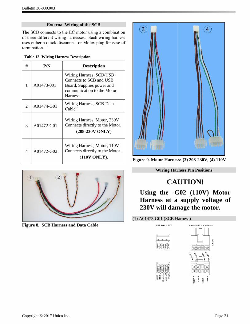
The SCB connects to the EC motor using a combination
of three different wiring harnesses. Each wiring harness
uses either a quick disconnect or Molex plug for ease of
termination.
Table 13. Wiring Harness Description
# P/N Description
1 A01473-001
Wiring Harness, SCB/USB
Connects to SCB and USB
Board, Supplies power and
communication to the Motor
Harness.
2 A01474-G01 Wiring Harness, SCB Data
Cable”
Links SCB to USB board
3 A01472-G01
Wiring Harness, Motor, 230V
Connects directly to the Motor.
(208-230V ONLY)
4 A01472-G02
Wiring Harness, Motor, 110V
Connects directly to the Motor.
(110V ONLY).
Figure 8. SCB Harness and Data Cable
Figure 9. Motor Harness: (3) 208-230V, (4) 110V
Wiring Harness Pin Positions
CAUTION!
Using the -G02 (110V) Motor
Harness at a supply voltage of
230V will damage the motor.
(1) A01473-G01 (SCB Harness)
Bulletin 30-039.003
Copyright © 2017 Unico Inc. Page 22
(2) A01474-G01 (Data Cable)
(3) A01472-G01 (230V Motor Harness)
(4) A01472-G02 (110V Motor Harness)
Cable Connections to the USB Board
Figure 10. USB board.
Programming the SCB
The SCB switches allow the user to select from two
different default high-cool airflow rates for each model
blower by changing the position of the “CFM” or
“Capacity” switch, depending on the modelof the control
board [refer to Table 3 for the default values]. These
settings are based on design airflow requirements for
refrigerant cooling coils and should be sufficient for most
applications. The default airflow for all other modes of
operation are a percentage of the high-cool value and can
be found in Table 2. However, if the installation calls for
a modification, each airflow can be individually modified
using the Unico ECMConfig program.
Compatibility. The ECMConfig software requires the
use of a Windows XP/7/8 operating system. Use of a
Windows emulator for Mac systems may be possible, but
is not supported. The software requires .NET version 3.5
or later. The ECMConfig installer will automatically
check for this.
Installation. A software installation CD ships with every
SCB control box. This software can also be downloaded
from: http://tech.unicosystem.com/ . If you have an older
version of the software, you will first need to uninstall it.
The installer will search your operating system for the
correct .NET framework and automatically install it if it
is not found. If using the CD, simply insert and follow the
instructions. If the installer does not automatically begin,
go the the Start button, select RUN and type
“drive://ECMconfig.msi”.
Connecting your computer. After the software is
installed, connect your computer to the control box using
the included USB cable (Type A/B). Start the program
and apply power to the control box. Your computer
should immediately recognize the control box and the
software will indicate that it is connected.
Figure 11. Location of USB (computer) port
Bulletin 30-039.003
Copyright © 2017 Unico Inc. Page 23
Startup and Main Tab
Upon startup, you will see a temporary ‘splash’ screen,
and then the Main tab of the ECMConfig program. There
are three Tabs: Main, Air Cycle and Switches. The Main
tab is used to set the Airflow and RPM Limit for each
Mode of operation. It also provides information on the
current airflow and fan RPM, as well as the Model
number of the blower as identified by the motor size and
position of the MOD and AUX switches. The blower
model and any calls from the thermostat will be
highlighted on this screen, as shown in Figure 12. If the
highlighted model is not what is installed, set the switches
to the correct position for your model blower as shown in
tables 4a and 4b, and cycle the power to the SCB.
Figure 12. ECMConfig Main Tab. Model number and
thermostat calls highlighted.
Communication Status
At the bottom of the ECMConfig window is a graphic that
shows the blower, USB board, SCB board and your
computer, and indicates the current communication status
between each component. Moving dots indicate that
communication between two adjoining components has
been established and red “X’ marks indicate that there is
no communication. Red error messages will be displayed
that indicate the source of the problem. The most likely
problem is no power to the SCB or motor, or a bad cable.
See table 14 for more details.
Bulletin 30-039.003
Copyright © 2017 Unico Inc. Page 24
Table 14. Communication Error codes.
Symbol Error
Message/Symbol Interpretation Action
Normal Operation
Shown.
Proper Communication
Established.
None.
Unable to open
computer port.
Scanning for ports.
“X” between
Computer and USB
board.
Computer cannot
communicate with USB
board.
USB board or cables may
be faulty or disconnected.
The COM port assigned to
the USB board may be too
high.
1.) Check for loose USB cable.
2.) Check that Red, Green LEDS
on USB board are flashing.
3.) Check Device Manager. Set
COM port value to 16 or less.
4.) Reinstall Software.
No communication
with SCB board.
“X” between USB
board and SCB
board.
Computer cannot
communicate with SCB
board.
SCB cable is not connected
or is faulty.
1.) Check that the SCB board has
power.
2.) Reseat multi-colored cable
between USB board and SCB.,
cable A01474-G01
No communication
with motor.
“X” between USB
board and motor.
SCB cannot communicate
with the motor.
1.) Check power to the motor.
Check power wires on cables
A01473-G01 and A01472-G0x
2.) Check the 4-wire twisted data
cable (part of A01473-G01)
connected between the USB
board and the motor cable.
3.) Check 4 black data wires (part
of cable A01472-G0x) from
motor to USB board.
Bulletin 30-039.003
Copyright © 2017 Unico Inc. Page 25
Actual Airflow
This is the current actual airflow. This value will
fluctuate as the motor ramps to achieve the Requested
Airflow. Once Actual Speed is stable (no longer
increasing), the “Actual Airflow” is accurate.
Figure 13. Real Time Actual CFM
Actual Speed
The program queries the motor for the motor speed in
revolutions per minute. This value is exact and will
fluctuate somewhat as the motor attempts to hold the
airflow constant.
Figure 14. Real Time Motor Speed
Lock to HiCool
If this box is checked, the airflow will be locked to the
High Cool (Y2) mode at the default percentage shown
in Table 3. You must uncheck this box before you can
change the requested airflow for a particular mode.
This will change the input box for requested airflow
from gray to white, indicating that you can edit its
contents.
Figure 15. Lock to Hi Cool.
Air Cycle Indicator
The program indicates the mode of operation by
highlighting the mode in yellow. It is possible to have
more than one mode highlighted. For example, if the
Air Cycle switch is in the “on” position and the
thermostat is calling for low cooling, then both of those
modes will be highlighted. The program will display
the words “Air Cycle” when that mode is operating.
Figure 16. Air Cycle mode
Requested Airflow
Figure 17. Requested Airflow
The airflow for each mode can be modified
individually. To modify the airflow enter the desired
value with the number pad or use the up/down arrows
to change incrementally. Any changes are saved to the
SCB memory immediately. The program will not
allow you to enter a value outside the minimum and
maximum airflows as shown in Table 15.
Table 15. Airflow range by model number.
Blower
Model
Minimum
Airflow
Maximum
Airflow
CFM (L/s) CFM (L/s)
1218 100 (47) 500 (236)
2430 200 (95) 750 (353)
3036 300 (142) 900 (425)
3642 300 (142) 1200 (566)
4860 400 (189) 1500 (707)
510 1416
ActualAirflow Actual Speed
CFM RPM
1218 2430 3036 3642 4860
Lock toHiCool
RequestedAirflow
ThermostatOverride
RequestedSpeed Limit
Model Number
510 1416
ActualAirflow Actual Speed
CFM RPM
1218 2430 3036 3642 4860
Lock toHiCool
RequestedAirflow
ThermostatOverride
RequestedSpeed Limit
Model Number
Air Cycle
Lo Cool
500 1800
375 1800
250 1800
375 1800
500 1800
500 1800
Bulletin 30-039.003
Copyright © 2017 Unico Inc. Page 26
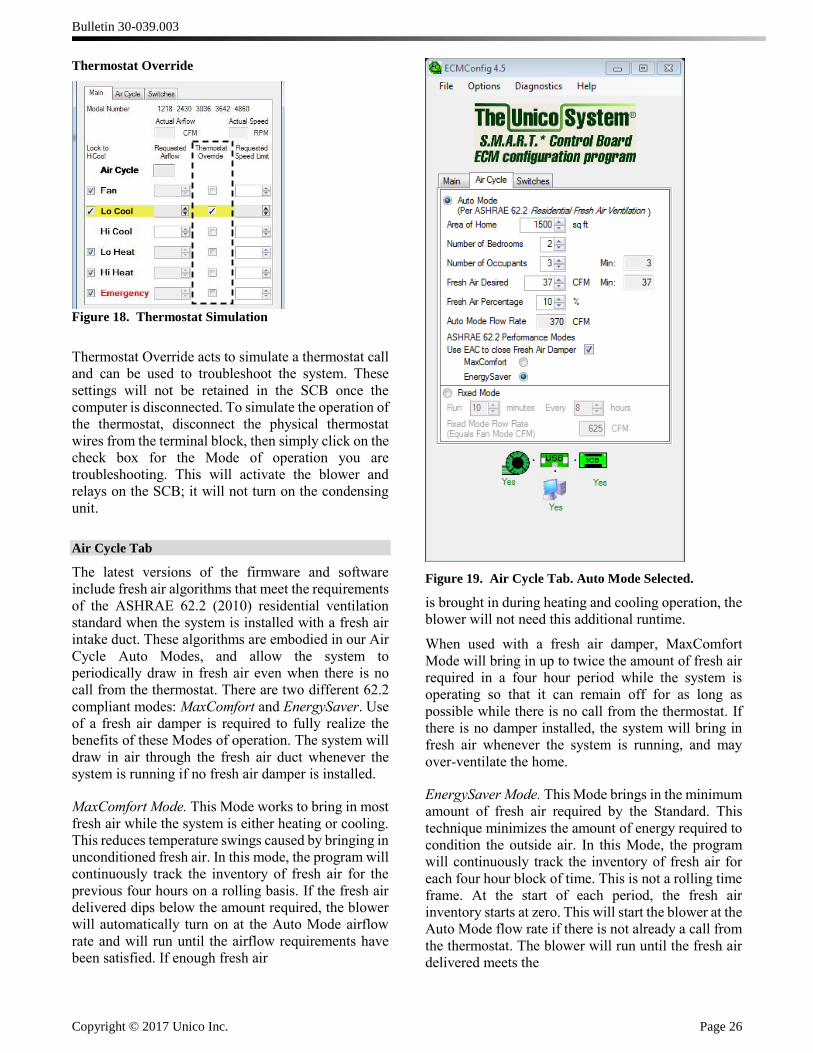
Thermostat Override
Figure 18. Thermostat Simulation
Thermostat Override acts to simulate a thermostat call
and can be used to troubleshoot the system. These
settings will not be retained in the SCB once the
computer is disconnected. To simulate the operation of
the thermostat, disconnect the physical thermostat
wires from the terminal block, then simply click on the
check box for the Mode of operation you are
troubleshooting. This will activate the blower and
relays on the SCB; it will not turn on the condensing
unit.
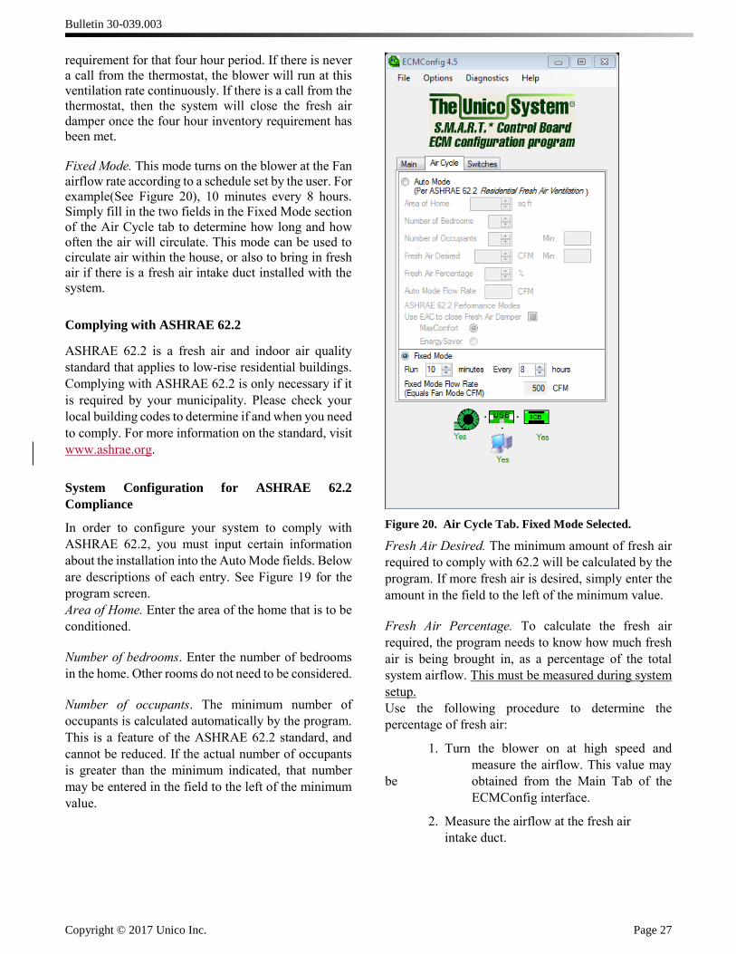
Air Cycle Tab
The latest versions of the firmware and software
include fresh air algorithms that meet the requirements
of the ASHRAE 62.2 (2010) residential ventilation
standard when the system is installed with a fresh air
intake duct. These algorithms are embodied in our Air
Cycle Auto Modes, and allow the system to
periodically draw in fresh air even when there is no
call from the thermostat. There are two different 62.2
compliant modes: MaxComfort and EnergySaver. Use
of a fresh air damper is required to fully realize the
benefits of these Modes of operation. The system will
draw in air through the fresh air duct whenever the
system is running if no fresh air damper is installed.
MaxComfort Mode. This Mode works to bring in most
fresh air while the system is either heating or cooling.
This reduces temperature swings caused by bringing in
unconditioned fresh air. In this mode, the program will
continuously track the inventory of fresh air for the
previous four hours on a rolling basis. If the fresh air
delivered dips below the amount required, the blower
will automatically turn on at the Auto Mode airflow
rate and will run until the airflow requirements have
been satisfied. If enough fresh air
Figure 19. Air Cycle Tab. Auto Mode Selected.
is brought in during heating and cooling operation, the
blower will not need this additional runtime.
When used with a fresh air damper, MaxComfort
Mode will bring in up to twice the amount of fresh air
required in a four hour period while the system is
operating so that it can remain off for as long as
possible while there is no call from the thermostat. If
there is no damper installed, the system will bring in
fresh air whenever the system is running, and may
over-ventilate the home.
EnergySaver Mode. This Mode brings in the minimum
amount of fresh air required by the Standard. This
technique minimizes the amount of energy required to
condition the outside air. In this Mode, the program
will continuously track the inventory of fresh air for
each four hour block of time. This is not a rolling time
frame. At the start of each period, the fresh air
inventory starts at zero. This will start the blower at the
Auto Mode flow rate if there is not already a call from
the thermostat. The blower will run until the fresh air
delivered meets the
Air Cycle
Lo Cool
Bulletin 30-039.003
Copyright © 2017 Unico Inc. Page 27
requirement for that four hour period. If there is never
a call from the thermostat, the blower will run at this
ventilation rate continuously. If there is a call from the
thermostat, then the system will close the fresh air
damper once the four hour inventory requirement has
been met.
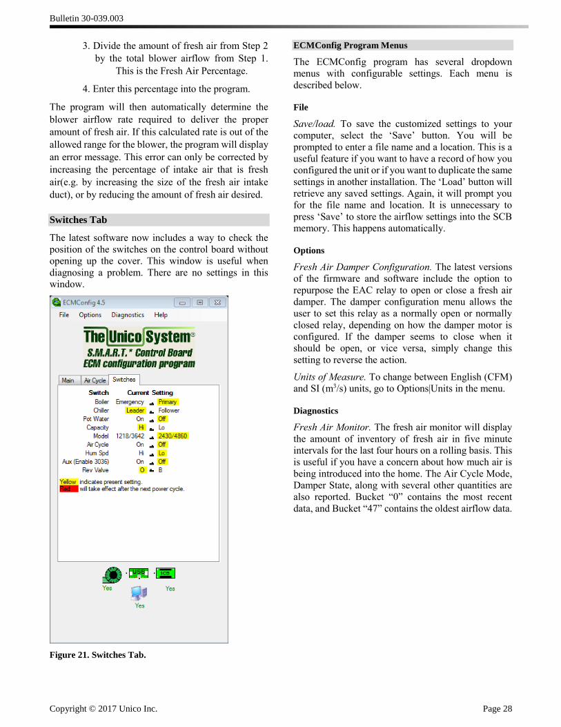
Fixed Mode. This mode turns on the blower at the Fan
airflow rate according to a schedule set by the user. For
example(See Figure 20), 10 minutes every 8 hours.
Simply fill in the two fields in the Fixed Mode section
of the Air Cycle tab to determine how long and how
often the air will circulate. This mode can be used to
circulate air within the house, or also to bring in fresh
air if there is a fresh air intake duct installed with the
system.
Complying with ASHRAE 62.2
ASHRAE 62.2 is a fresh air and indoor air quality
standard that applies to low-rise residential buildings.
Complying with ASHRAE 62.2 is only necessary if it
is required by your municipality. Please check your
local building codes to determine if and when you need
to comply. For more information on the standard, visit
www.ashrae.org.
System Configuration for ASHRAE 62.2
Compliance
In order to configure your system to comply with
ASHRAE 62.2, you must input certain information
about the installation into the Auto Mode fields. Below
are descriptions of each entry. See Figure 19 for the
program screen.
Area of Home. Enter the area of the home that is to be
conditioned.
Number of bedrooms. Enter the number of bedrooms
in the home. Other rooms do not need to be considered.
Number of occupants. The minimum number of
occupants is calculated automatically by the program.
This is a feature of the ASHRAE 62.2 standard, and
cannot be reduced. If the actual number of occupants
is greater than the minimum indicated, that number
may be entered in the field to the left of the minimum
value.
Figure 20. Air Cycle Tab. Fixed Mode Selected.
Fresh Air Desired. The minimum amount of fresh air
required to comply with 62.2 will be calculated by the
program. If more fresh air is desired, simply enter the
amount in the field to the left of the minimum value.
Fresh Air Percentage. To calculate the fresh air
required, the program needs to know how much fresh
air is being brought in, as a percentage of the total
system airflow. This must be measured during system
setup.
Use the following procedure to determine the
percentage of fresh air:
1. Turn the blower on at high speed and
measure the airflow. This value may
be obtained from the Main Tab of the
ECMConfig interface.
2. Measure the airflow at the fresh air
intake duct.
Bulletin 30-039.003
Copyright © 2017 Unico Inc. Page 28
3. Divide the amount of fresh air from Step 2
by the total blower airflow from Step 1.
This is the Fresh Air Percentage.
4. Enter this percentage into the program.
The program will then automatically determine the
blower airflow rate required to deliver the proper
amount of fresh air. If this calculated rate is out of the
allowed range for the blower, the program will display
an error message. This error can only be corrected by
increasing the percentage of intake air that is fresh
air(e.g. by increasing the size of the fresh air intake
duct), or by reducing the amount of fresh air desired.
Switches Tab
The latest software now includes a way to check the
position of the switches on the control board without
opening up the cover. This window is useful when
diagnosing a problem. There are no settings in this
window.
Figure 21. Switches Tab.
ECMConfig Program Menus
The ECMConfig program has several dropdown
menus with configurable settings. Each menu is
described below.
File
Save/load. To save the customized settings to your
computer, select the ‘Save’ button. You will be
prompted to enter a file name and a location. This is a
useful feature if you want to have a record of how you
configured the unit or if you want to duplicate the same
settings in another installation. The ‘Load’ button will
retrieve any saved settings. Again, it will prompt you
for the file name and location. It is unnecessary to
press ‘Save’ to store the airflow settings into the SCB
memory. This happens automatically.
Options
Fresh Air Damper Configuration. The latest versions
of the firmware and software include the option to
repurpose the EAC relay to open or close a fresh air
damper. The damper configuration menu allows the
user to set this relay as a normally open or normally
closed relay, depending on how the damper motor is
configured. If the damper seems to close when it
should be open, or vice versa, simply change this
setting to reverse the action.
Units of Measure. To change between English (CFM)
and SI (m3/s) units, go to Options|Units in the menu.
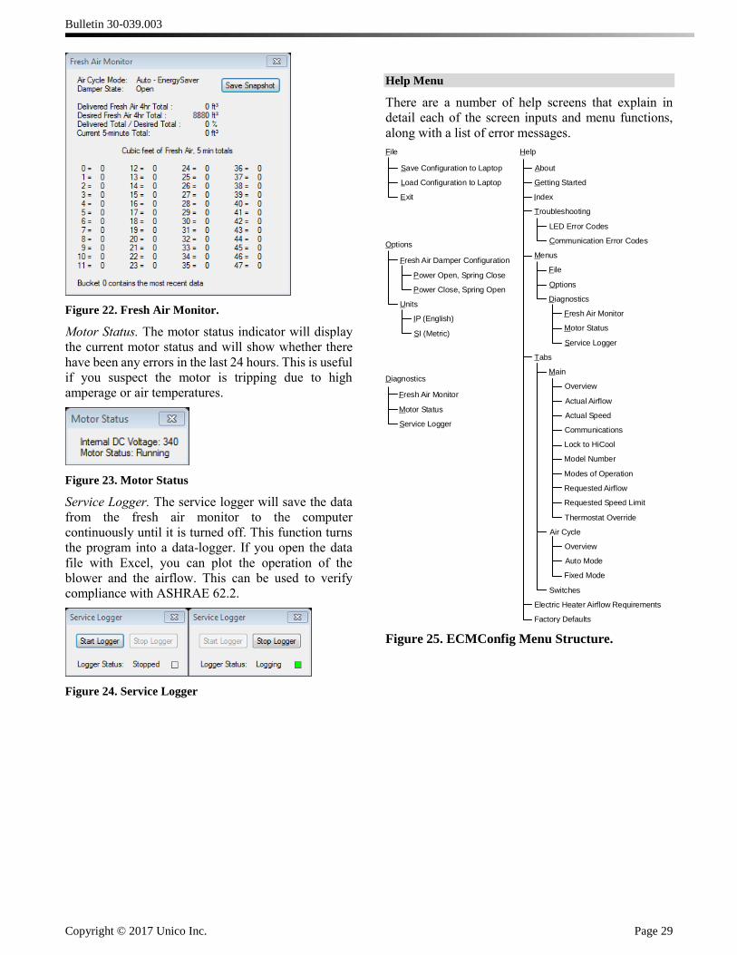
Diagnostics
Fresh Air Monitor. The fresh air monitor will display
the amount of inventory of fresh air in five minute
intervals for the last four hours on a rolling basis. This
is useful if you have a concern about how much air is
being introduced into the home. The Air Cycle Mode,
Damper State, along with several other quantities are
also reported. Bucket “0” contains the most recent
data, and Bucket “47” contains the oldest airflow data.
Bulletin 30-039.003
Copyright © 2017 Unico Inc. Page 29
Figure 22. Fresh Air Monitor.
Motor Status. The motor status indicator will display
the current motor status and will show whether there
have been any errors in the last 24 hours. This is useful
if you suspect the motor is tripping due to high
amperage or air temperatures.
Figure 23. Motor Status
Service Logger. The service logger will save the data
from the fresh air monitor to the computer
continuously until it is turned off. This function turns
the program into a data-logger. If you open the data
file with Excel, you can plot the operation of the
blower and the airflow. This can be used to verify
compliance with ASHRAE 62.2.
Figure 24. Service Logger
Help Menu
There are a number of help screens that explain in
detail each of the screen inputs and menu functions,
along with a list of error messages.
Figure 25. ECMConfig Menu Structure.
File
Save Configuration to Laptop
Load Configuration to Laptop
Exit
Options
Fresh Air Damper Configuration
Power Open, Spring Close
Power Close, Spring Open
Units
IP (English)
SI (Metric)
Diagnostics
Fresh Air Monitor
Motor Status
Service Logger
Help
About
Getting Started
Index
Troubleshooting
LED Error Codes
Communication Error Codes
Menus
File
Options
Diagnostics
Fresh Air Monitor
Motor Status
Service Logger
Tabs
Main
Overview
Actual Airflow
Actual Speed
Communications
Lock to HiCool
Model Number
Modes of Operation
Requested Airflow
Requested Speed Limit
Thermostat Override
Air Cycle
Overview
Auto Mode
Fixed Mode
Switches
Electric Heater Airflow Requirements
Factory Defaults
Bulletin 30-039.003
Copyright © 2017 Unico Inc. Page 30
Troubleshooting
Default Airflow seems too High/Low
Check that the MOD switch on the SCB is in the
correct position. If not, select the appropriate model
and cycle the power.
Note: If the model switch is set for 1218 and is
connected to a ½ hp motor, the blower will spin
counter-clockwise. If the model switch is set for
2430 the blower will spin clockwise.
Check the air flow against the default setting listed in
Table 2. The Flash LED (previously PCB Ctrl LED)
will flash the actual airflow in CFM. A long flash
indicates 100 cfm and a short flash at the end of the
long flashes indicates 50 cfm (example: 7 long flashes
followed by a short flash indicate an actual airflow of
750 cfm). If the blower reaches its RPM limit, an extra-
long flash will occur between the CFM sequences. The
maximum motor speed is 1800 RPM which is the
default limit. Check to see that the limit is not too low.
If motor speed limit is at 1800 RPM then add more
outlets or change the plenum design to decrease the
duct friction.
Fan does not run
“Power” LED off? SCB is not receiving power. The
SCB LED’s are activated by 24V. Check to make sure
the transformer is getting 230V or 110V and then
check to make sure the output of the transformer is
delivering 24V (Common problem is a loose
connection).
“Power” LED on but not flashing? SCB has power
but processor is not executing. Disconnect power, wait
10 seconds, reconnect power.
Is the thermostat energizing G, W or Y? Check if
24Vac exists from C to G, W, Y1, Y2, or E. If no
voltage exists on any of these, check connection
between SCB and the thermostat. Check connection at
the thermostat or replace the thermostat.
If 24Vac does exist on G, W, or Y check the Heat LED
on the SCB. Flashing indicates the motor has lost
communication. Inspect the connections between the
control box and the motor. Disconnect and reset the
motor connector. Check that the motor is free to turn.
Fan runs without demand from thermostat
The software in the board will automatically turn the
fan on for the following conditions:
1. The humidistat is calling for humidity and
there is no call for heating.
2. The winter cycling function is activated (fixed
mode).
3. The fresh air cycling function is activated.
4. The blower is ramping down after shut down.
Is “Power” LED flashing? If not, the processor has
stopped executing, remove and reapply power.
Heat pump compressor runs in heat mode but
does not run for air conditioning.
AFS (automatic frost switch) input is open. The AFS
terminals must be connected to a frost switch.
Heat pump compressor runs but is cooling
when it should be heating or heating when it
should be cooling.
Is the “Reversing Valve” switch set properly? (If the
outdoor reversing valve requires 24vac for heating,
then the Reversing Valve switch should be switched to
“B” and the jumper wire must be cut.
3rd stage electric heat (S3) does not energize
Is the thermostat demanding heat pump operation?
This is normal. The third stage is disabled during heat
pump operation.