smart condition monitoring with iiot sensors
TRANSCRIPT
SITRANS SCM IQ
DigitalizationSmart Condition Monitoring with IIoT Sensors
Operating Instructions
7MP2200-1CB05-2AA1 (SITRANS CC220)7MP2210-2AB21-2AB1 (SITRANS MS200)MindSphere application SITRANS SCM IQ
11/2021A5E50573389-AB
Getting started 1Introduction 2Safety notes 3Description 4Installing/mounting 5Connecting SITRANS CC220 6Commissioning 7Operating 8Service and maintenance 9Diagnostics and troubleshooting 10
Technical specifications 11Dimension drawings 12Product documentation and support A
Ordering data B

Legal informationWarning notice system
This manual contains notices you have to observe in order to ensure your personal safety, as well as to prevent damage to property. The notices referring to your personal safety are highlighted in the manual by a safety alert symbol, notices referring only to property damage have no safety alert symbol. These notices shown below are graded according to the degree of danger.
DANGERindicates that death or severe personal injury will result if proper precautions are not taken.
WARNINGindicates that death or severe personal injury may result if proper precautions are not taken.
CAUTIONindicates that minor personal injury can result if proper precautions are not taken.
NOTICEindicates that property damage can result if proper precautions are not taken.If more than one degree of danger is present, the warning notice representing the highest degree of danger will be used. A notice warning of injury to persons with a safety alert symbol may also include a warning relating to property damage.
Qualified PersonnelThe product/system described in this documentation may be operated only by personnel qualified for the specific task in accordance with the relevant documentation, in particular its warning notices and safety instructions. Qualified personnel are those who, based on their training and experience, are capable of identifying risks and avoiding potential hazards when working with these products/systems.
Proper use of Siemens productsNote the following:
WARNINGSiemens products may only be used for the applications described in the catalog and in the relevant technical documentation. If products and components from other manufacturers are used, these must be recommended or approved by Siemens. Proper transport, storage, installation, assembly, commissioning, operation and maintenance are required to ensure that the products operate safely and without any problems. The permissible ambient conditions must be complied with. The information in the relevant documentation must be observed.
TrademarksAll names identified by ® are registered trademarks of Siemens AG. The remaining trademarks in this publication may be trademarks whose use by third parties for their own purposes could violate the rights of the owner.
Disclaimer of LiabilityWe have reviewed the contents of this publication to ensure consistency with the hardware and software described. Since variance cannot be precluded entirely, we cannot guarantee full consistency. However, the information in this publication is reviewed regularly and any necessary corrections are included in subsequent editions.
Siemens AGDigital IndustriesPostfach 48 4890026 NÜRNBERGGERMANY
Document order number: A5E50573389Ⓟ 11/2021 Subject to change
Copyright © Siemens AG 2021.All rights reserved
Table of contents
1 Getting started ...................................................................................................................................... 72 Introduction ........................................................................................................................................... 9
2.1 Purpose of this documentation ............................................................................................ 92.2 Document history ................................................................................................................ 92.3 FW revision history............................................................................................................... 92.4 Designated use .................................................................................................................... 92.5 Checking the consignment................................................................................................. 102.6 Industrial use note ............................................................................................................. 102.7 Security information .......................................................................................................... 102.8 Transportation and storage ................................................................................................ 112.9 Notes on warranty ............................................................................................................. 11
3 Safety notes ......................................................................................................................................... 133.1 Preconditions for use ......................................................................................................... 133.1.1 Laws and directives ............................................................................................................ 133.1.2 Conformity with European directives .................................................................................. 133.1.3 Improper device modifications............................................................................................ 143.2 Requirements for special applications................................................................................. 143.3 Basic safety notes SITRANS CC220 ...................................................................................... 153.3.1 Basic safety notes............................................................................................................... 153.3.2 Data protection ................................................................................................................. 163.3.3 Notes on use...................................................................................................................... 163.4 Basic safety notes SITRANS MS200 ..................................................................................... 173.4.1 Lithium batteries................................................................................................................ 173.4.2 Halogen and silicone.......................................................................................................... 173.4.3 ESD Guideline .................................................................................................................... 173.4.4 Battery pack specification ................................................................................................... 18
4 Description........................................................................................................................................... 194.1 System description............................................................................................................. 194.2 SITRANS CC220 design....................................................................................................... 214.3 SITRANS MS200 design ...................................................................................................... 22
5 Installing/mounting ............................................................................................................................. 235.1 Installation instructions SITRANS CC220 ............................................................................. 235.1.1 Mounting SITRANS CC220.................................................................................................. 235.1.2 Mounting positions and mounting types ............................................................................ 255.1.3 Mounting on DIN rails ........................................................................................................ 265.1.4 Mounting on a wall............................................................................................................ 27
Smart Condition Monitoring with IIoT SensorsOperating Instructions, 11/2021, A5E50573389-AB 3

5.2 Installation instructions SITRANS MS200 ............................................................................ 285.2.1 Basic safety notes SITRANS MS200 ..................................................................................... 285.2.1.1 Installation location requirements ...................................................................................... 295.2.2 General description............................................................................................................ 305.2.3 Installing SITRANS MS200 on a pump or compressor .......................................................... 315.2.4 Installing SITRANS MS200 on a gear ................................................................................... 315.2.5 Installing SITRANS MS200 on rotating or vibrating equipment ............................................ 315.3 Disassembly SITRANS MS200.............................................................................................. 32
6 Connecting SITRANS CC220................................................................................................................. 336.1 Basic safety notes............................................................................................................... 336.1.1 Improvement of interference immunity .............................................................................. 346.2 Connecting SITRANS CC220 ............................................................................................... 34
7 Commissioning .................................................................................................................................... 377.1 Basic safety notes............................................................................................................... 377.2 Starting SITRANS SCM IQ in MindSphere............................................................................. 377.3 Administrating the network for SITRANS CC220.................................................................. 387.4 Powering up SITRANS MS200 ............................................................................................. 387.5 Integrating SITRANS MS200 to MindSphere Asset Manager................................................. 407.6 Commissioning SITRANS CC220 with SITRANS SCM IQ ........................................................ 417.7 Commissioning SITRANS MS200 with SITRANS SCM IQ ....................................................... 437.8 Configuring notifications .................................................................................................... 44
8 Operating............................................................................................................................................. 478.1 Training anomaly detection models .................................................................................... 478.2 Managing anomalies in SITRANS Anomaly IQ...................................................................... 498.3 Disconnecting SITRANS CC220 and SITRANS MS200 ........................................................... 508.4 Resetting or disconnecting SITRANS CC220 from SITRANS SCM IQ (Offboarding) ................. 518.5 Resetting SITRANS MS200 .................................................................................................. 518.6 Accessing the OSS Readme and source code....................................................................... 52
9 Service and maintenance .................................................................................................................... 539.1 Maintenance and repair work for SITRANS CC220 ............................................................... 539.1.1 Basic safety notes............................................................................................................... 539.1.1.1 Repair information ............................................................................................................. 549.1.2 Sending the log files to technical support ........................................................................... 549.1.3 Replacing the backup battery ............................................................................................. 569.1.4 Replacing SITRANS CC220 .................................................................................................. 579.2 Maintenance and repair work for SITRANS MS200 .............................................................. 579.2.1 Basic safety notes............................................................................................................... 579.2.2 Replacing SITRANS MS200 battery pack.............................................................................. 589.2.3 Replacing SITRANS MS200 ................................................................................................. 629.3 Cleaning ............................................................................................................................ 64
Table of contents
Smart Condition Monitoring with IIoT Sensors4 Operating Instructions, 11/2021, A5E50573389-AB

9.4 Return procedure ............................................................................................................... 659.5 Disposal............................................................................................................................. 65
10 Diagnostics and troubleshooting......................................................................................................... 6710.1 Meaning of the LED states on SITRANS CC220 .................................................................... 6710.2 Troubleshooting................................................................................................................. 67
11 Technical specifications ....................................................................................................................... 6911.1 Technical specifications SITRANS CC220.............................................................................. 6911.2 Technical specifications SITRANS MS200............................................................................. 71
12 Dimension drawings ............................................................................................................................ 7312.1 Dimension drawings SITRANS CC220.................................................................................. 7312.2 Dimension drawings SITRANS MS200 ................................................................................. 74
A Product documentation and support .................................................................................................. 75A.1 Product documentation ..................................................................................................... 75A.2 Technical support............................................................................................................... 76
B Ordering data ...................................................................................................................................... 77B.1 Accessories ........................................................................................................................ 77Index .................................................................................................................................................... 79
Table of contents
Smart Condition Monitoring with IIoT SensorsOperating Instructions, 11/2021, A5E50573389-AB 5

Table of contents
Smart Condition Monitoring with IIoT Sensors6 Operating Instructions, 11/2021, A5E50573389-AB
Getting started 1Before commissioning the devices
Observe the following safety instructions:• General safety notes (Page 13)• Basic safety notes: Installing/mounting (Page 28)• Basic safety notes: Connecting (Page 33)Read the entire operating instructions in order to achieve the optimum performance of the system.
Procedure1. Start SITRANS SCM IQ in MindSphere as an admin the very first time after provisioning.
Starting SITRANS SCM IQ in MindSphere (Page 37)You need to perform this task only the very first time after launching SITRANS SCM IQ to MindSphere. You do not need to repeat this task at a later stage.
2. Mount SITRANS CC220.Mounting SITRANS CC220 (Page 23)
3. Connect SITRANS CC220.Connecting SITRANS CC220 (Page 34)
4. Power up SITRANS MS200.Powering up SITRANS MS200 (Page 38)
5. Mount SITRANS MS200.Installation instructions SITRANS MS200 (Page 28)
6. Integrate SITRANS MS200 to MindSphere Asset Manager.Integrating SITRANS MS200 to MindSphere Asset Manager (Page 40)
7. Commission SITRANS CC220 with SITRANS SCM IQ.Commissioning SITRANS CC220 with SITRANS SCM IQ (Page 41)
8. Commission SITRANS MS200 with SITRANS SCM IQ.Commissioning SITRANS MS200 with SITRANS SCM IQ (Page 43)
9. Configure the user notifications in SITRANS SCM IQ.Configuring notifications (Page 44)
10.As soon as SITRANS MS200 has collected measurement data, train machine learning models and manage detected anomalies.Training anomaly detection models (Page 47)Managing anomalies in SITRANS Anomaly IQ (Page 49)
Smart Condition Monitoring with IIoT SensorsOperating Instructions, 11/2021, A5E50573389-AB 7

Getting started
Smart Condition Monitoring with IIoT Sensors8 Operating Instructions, 11/2021, A5E50573389-AB
Introduction 22.1 Purpose of this documentation
These instructions contain all information required to commission and use the devices. Read the instructions carefully prior to installation and commissioning. In order to use the devices correctly, first review its principle of operation.The instructions are aimed at persons mechanically installing the devices, connecting it electronically, configuring the parameters and commissioning it, as well as service and maintenance engineers.
2.2 Document historyThe following table shows major changes in the documentation compared to the previous edition.
Edition Remark11/2021 The following sections have been revised:
Basic safety notes SITRANS CC220 (Page 15) Technical specifications (Page 69) FW revision history (Page 9)
08/2021 First edition
2.3 FW revision historySITRANS CC220Firmware revision Date Changes1.00.01 11/2021 Stability improvement1.00.00 08/2021 Initial release
SITRANS MS200Firmware revision Date Changes1.0.0 08/2021 Initial release
2.4 Designated useUse the device in accordance with the information on the nameplate and in the Technical specifications (Page 69).
Smart Condition Monitoring with IIoT SensorsOperating Instructions, 11/2021, A5E50573389-AB 9
2.5 Checking the consignment1. Check the packaging and the delivered items for visible damages.2. Report any claims for damages immediately to the shipping company.3. Retain damaged parts for clarification.4. Check the scope of delivery by comparing your order to the shipping documents for
correctness and completeness.
2.6 Industrial use note
NOTICEUse in a domestic environmentThis Class A Group 1 equipment is intended for use in industrial areas.In a domestic environment this device may cause radio interference.
2.7 Security informationSiemens provides products and solutions with industrial security functions that support the secure operation of plants, systems, machines and networks.In order to protect plants, systems, machines and networks against cyber threats, it is necessary to implement – and continuously maintain – a holistic, state-of-the-art industrial security concept. Siemens’ products and solutions constitute one element of such a concept.Customers are responsible for preventing unauthorized access to their plants, systems, machines and networks. Such systems, machines and components should only be connected to an enterprise network or the internet if and to the extent such a connection is necessary and only when appropriate security measures (e.g. firewalls and/or network segmentation) are in place.For additional information on industrial security measures that may be implemented, please visit https://www.siemens.com/industrialsecurity. Siemens’ products and solutions undergo continuous development to make them more secure. Siemens strongly recommends that product updates are applied as soon as they are available and that the latest product versions are used. Use of product versions that are no longer supported, and failure to apply the latest updates may increase customer’s exposure to cyber threats.To stay informed about product updates, subscribe to the Siemens Industrial Security RSS Feed under https://www.siemens.com/industrialsecurity.
Introduction2.7 Security information
Smart Condition Monitoring with IIoT Sensors10 Operating Instructions, 11/2021, A5E50573389-AB

Disclaimer for third-party software updatesThis product includes third-party software. Siemens AG only provides a warranty for updates/patches of the third-party software, if these have been distributed as part of a Siemens software update service contract or officially released by Siemens AG. Otherwise, updates/patches are undertaken at your own risk. You can find more information about our Software Update Service offer on the Internet at Software Update Service (https://support.industry.siemens.com/cs/ww/en/view/109759444).
Notes on protecting administrator accountsA user with administrator privileges has extensive access and manipulation options in the system.Therefore, ensure there are adequate safeguards for protecting the administrator accounts to prevent unauthorized changes. To do this, use secure passwords and a standard user account for normal operation. Other measures, such as the use of security policies, should be applied as needed.
2.8 Transportation and storageTo guarantee sufficient protection during transport and storage, observe the following:• Keep the original packaging for subsequent transportation.• Devices/replacement parts should be returned in their original packaging.• If the original packaging is no longer available, ensure that all shipments are properly
packaged to provide sufficient protection during transport. Siemens cannot assume liability for any costs associated with transportation damages.NOTICEInsufficient protection during storageThe packaging only provides limited protection against moisture and infiltration.• Provide additional packaging as necessary.
Special conditions for storage and transportation of the device are listed in Technical specifications (Page 69).
2.9 Notes on warrantyThe contents of this manual shall not become part of or modify any prior or existing agreement, commitment or legal relationship. The sales contract contains all obligations on the part of Siemens as well as the complete and solely applicable warranty conditions. Any statements regarding device versions described in the manual do not create new warranties or modify the existing warranty.The content reflects the technical status at the time of publishing. Siemens reserves the right to make technical changes in the course of further development.
Introduction2.9 Notes on warranty
Smart Condition Monitoring with IIoT SensorsOperating Instructions, 11/2021, A5E50573389-AB 11

Introduction2.9 Notes on warranty
Smart Condition Monitoring with IIoT Sensors12 Operating Instructions, 11/2021, A5E50573389-AB

Safety notes 33.1 Preconditions for use
This devices left the factory in good working condition. In order to maintain this status and to ensure safe operation of the devices, observe these instructions and all the specifications relevant to safety.Observe the information and symbols on the devices. Do not remove any information or symbols from the devices. Always keep the information and symbols in a completely legible state.
3.1.1 Laws and directivesObserve the safety rules, provisions and laws applicable in your country during connection, assembly and operation. These include, for example: • National Electrical Code (NEC - NFPA 70) (USA)• Canadian Electrical Code (CEC Part I) (Canada)Further provisions for hazardous area applications are for example: • IEC 60079-14 (international)• EN 60079-14 (EU and UK)
3.1.2 Conformity with European directivesThe CE marking on the device symbolizes the conformity with the following European directives:
2014/30/EUElectromagnetic compatibili‐ty EMC
Directive of the European Parliament and of the Council on the harmonisation of the laws of the Member States relating to elec‐tromagnetic compatibility
2014/53/EURED
Directive of the European Parliament and of the Council on the harmonisation of the laws of the Member States relating to the making available on the market of radio equipment and repeal‐ing Directive 1999/5/EC
2011/65/EURoHS
Directive of the European Parliament and the Council on the re‐striction of the use of certain hazardous substances in electrical and electronic equipment
The applicable directives can be found in the EU declaration of conformity of the specific device.
Smart Condition Monitoring with IIoT SensorsOperating Instructions, 11/2021, A5E50573389-AB 13

3.1.3 Improper device modifications
CAUTIONImproper device modifications Risk to personnel, system and environment can result from modifications to the device.• Do not carry out modifications to the device. Failure to observe this requirement cancels the
manufacturer's warranty and the product approvals.
3.2 Requirements for special applicationsDue to the large number of possible applications, each detail of the described device versions for each possible scenario during commissioning, operation, maintenance or operation in systems cannot be considered in the instructions. If you need additional information not covered by these instructions, contact your local Siemens office or company representative.
NoteOperation under special ambient conditionsWe highly recommend that you contact your Siemens representative or our application department before you operate the device under special ambient conditions as can be encountered in nuclear power plants or when the device is used for research and development purposes.
WARNINGCommissioning and operation with pending errorIf an error message appears, correct operation in the process is no longer guaranteed.• Check the gravity of the error.• Correct the error.• If the error still exists:
– Take the device out of operation.– Prevent renewed commissioning.
Safety notes3.2 Requirements for special applications
Smart Condition Monitoring with IIoT Sensors14 Operating Instructions, 11/2021, A5E50573389-AB
3.3 Basic safety notes SITRANS CC220
3.3.1 Basic safety notes
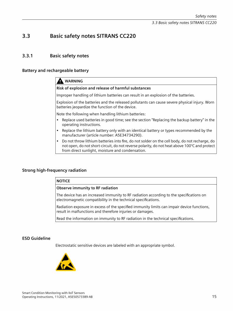
Battery and rechargeable battery
WARNINGRisk of explosion and release of harmful substancesImproper handling of lithium batteries can result in an explosion of the batteries. Explosion of the batteries and the released pollutants can cause severe physical injury. Worn batteries jeopardize the function of the device.Note the following when handling lithium batteries:• Replace used batteries in good time; see the section "Replacing the backup battery" in the
operating instructions.• Replace the lithium battery only with an identical battery or types recommended by the
manufacturer (article number: A5E34734290).• Do not throw lithium batteries into fire, do not solder on the cell body, do not recharge, do
not open, do not short-circuit, do not reverse polarity, do not heat above 100°C and protect from direct sunlight, moisture and condensation.
Strong high-frequency radiation
NOTICEObserve immunity to RF radiationThe device has an increased immunity to RF radiation according to the specifications on electromagnetic compatibility in the technical specifications.Radiation exposure in excess of the specified immunity limits can impair device functions, result in malfunctions and therefore injuries or damages.Read the information on immunity to RF radiation in the technical specifications.
ESD GuidelineElectrostatic sensitive devices are labeled with an appropriate symbol.
Safety notes3.3 Basic safety notes SITRANS CC220
Smart Condition Monitoring with IIoT SensorsOperating Instructions, 11/2021, A5E50573389-AB 15
NOTICEElectrostatic sensitive devices (ESD)When you touch electrostatic sensitive components, you can destroy them through voltages that are far below the human perception threshold.If you work with components that can be destroyed by electrostatic discharge, observe the ESD Guideline.
3.3.2 Data protection Siemens observes the data protection guidelines, especially the requirements regarding data minimization (privacy by design). This means the following for this product: The product does not process / save any personal information, but only technical functional data (e.g. time stamps). If the user links this data to other data (e.g. shift plans) or if the user saves personal information on the same medium (e.g. hard disk) and therefore creates a personal reference in the process, the user has to ensure meeting the guidelines regarding data protection.
3.3.3 Notes on use
NOTICEPossible functional restrictions in case of non-validated plant operationThe device is tested and certified based on the technical standards. In rare cases, functional restrictions can occur during plant operation.To avoid functional restrictions validate the correct functioning of the plant.
NoteUse in an industrial environment without additional protective measuresThis device is designed for use in a normal industrial environment.
Security notification• Follow the general security rules for networks.• Install hardware firewall before connecting to the internet. Install software firewall on the
device and open necessary ports only.• To protect sensitive data deploy DLP (data leakage protection) over your system. • Install the device in cabinets, separate rooms or controlled areas. Only authorized personnel
might access the device using locks or similar measures.• Always integrate security updates from latest example image or official upstream.
Safety notes3.3 Basic safety notes SITRANS CC220
Smart Condition Monitoring with IIoT Sensors16 Operating Instructions, 11/2021, A5E50573389-AB

• The device can be identified by collecting MAC/UID information from the system.• Note that the debug interface X14 on the motherboard is used for development purposes.• The micro USB port is only allowed to be used by Siemens personal.
3.4 Basic safety notes SITRANS MS200
3.4.1 Lithium batteriesLithium batteries are primary power sources with high energy content designed to provide the highest possible degree of safety.
WARNINGPotential hazardLithium batteries may present a potential hazard if they are abused electrically or mechanically. Observe the following precautions when handling and using lithium batteries:• Do not short-circuit, recharge or connect with false polarity.• Do not expose to temperatures beyond the specified temperature range.• Do not incinerate.• Do not crush, puncture or open cells or disassemble.• Do not weld or solder to the battery’s body.• Do not expose contents to water.
3.4.2 Halogen and silicone
NoteSITRANS MS200 may contain traces of halogen and silicone.
3.4.3 ESD GuidelineElectrostatic sensitive devices are labeled with an appropriate symbol.
Safety notes3.4 Basic safety notes SITRANS MS200
Smart Condition Monitoring with IIoT SensorsOperating Instructions, 11/2021, A5E50573389-AB 17

Electrostatic sensitive devices (ESD)When you touch electrostatic sensitive components, you can destroy them through voltages that are far below the human perception threshold.If you work with components that can be destroyed by electrostatic discharge, observe the ESD Guideline.
3.4.4 Battery pack specification
NOTICEUnsuitable battery packSITRANS MS200 is delivered with an LTC (Lithium Thionyl Chloride) battery pack offered by Siemens.• Use SITRANS MS200 with the delivered battery pack only.
See alsoAccessories (Page 77)
Safety notes3.4 Basic safety notes SITRANS MS200
Smart Condition Monitoring with IIoT Sensors18 Operating Instructions, 11/2021, A5E50573389-AB

Description 44.1 System description
SITRANS SCM IQ - Smart Condition Monitoring with IIoT SensorsWith SITRANS SCM IQ you can monitor the condition of the plant components of your process plant.The hardware basis of the SITRANS SCM IQ solution is the wireless SITRANS MS200 multisensor. SITRANS MS200 has two sensors on board for measuring vibration and temperature. SITRANS MS200 can be mounted on plant components such as pumps, gearboxes or compressors and collect information on vibrations and temperature. Using Bluetooth® low energy (BLE), the measurement data collected in SITRANS MS200 is sent to the SITRANS CC220 IIoT gateway. Max. 5 SITRANS MS200 can be connected to one SITRANS CC220. SITRANS CC220 transmits the information encrypted to MindSphere. In the SITRANS SCM IQ app, the status data of the monitored plant components or systems can be displayed graphically.For more information, watch this video (https://www.youtube.com/watch?v=-z4IaupJLjo).
Smart Condition Monitoring with IIoT SensorsOperating Instructions, 11/2021, A5E50573389-AB 19
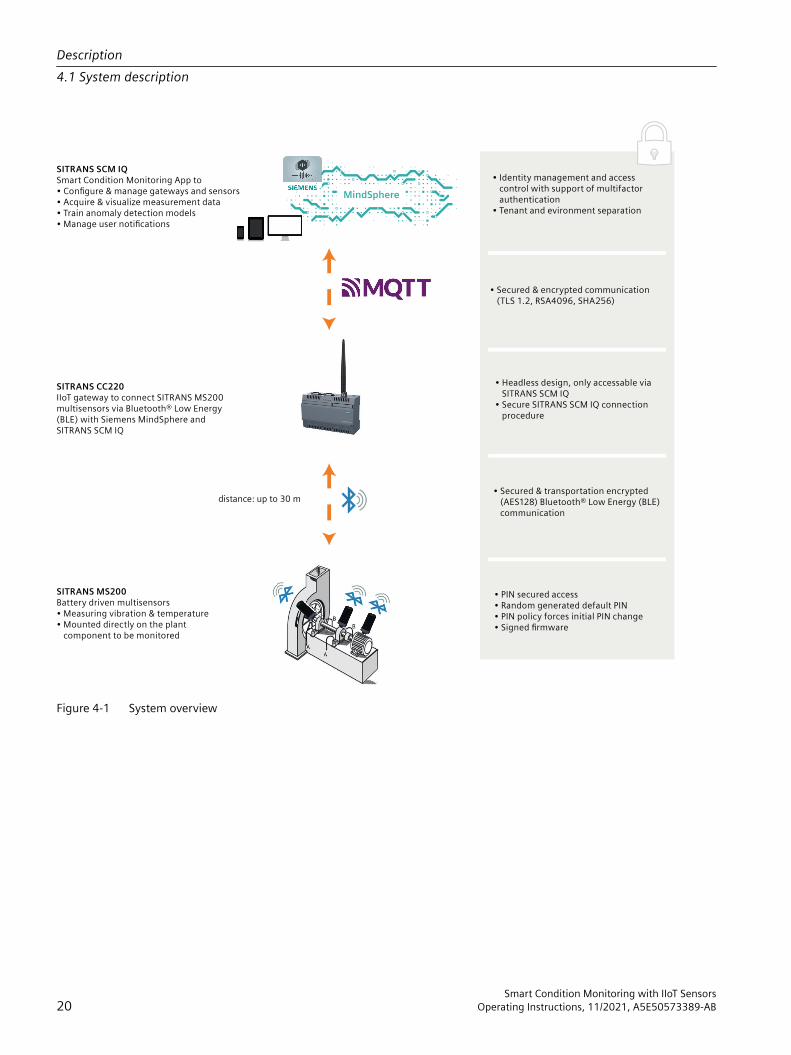
Figure 4-1 System overview
Description4.1 System description
Smart Condition Monitoring with IIoT Sensors20 Operating Instructions, 11/2021, A5E50573389-AB
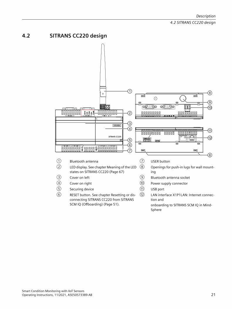
4.2 SITRANS CC220 design
① Bluetooth antenna ⑦ USER button② LED display. See chapter Meaning of the LED
states on SITRANS CC220 (Page 67)⑧ Openings for push-in lugs for wall mount‐
ing③ Cover on left ⑨ Bluetooth antenna socket④ Cover on right ⑩ Power supply connector⑤ Securing device ⑪ USB port⑥ RESET button. See chapter Resetting or dis‐
connecting SITRANS CC220 from SITRANS SCM IQ (Offboarding) (Page 51).
⑫ LAN interface X1P1LAN: Internet connec‐tion and onboarding to SITRANS SCM IQ in Mind‐Sphere
Description4.2 SITRANS CC220 design
Smart Condition Monitoring with IIoT SensorsOperating Instructions, 11/2021, A5E50573389-AB 21
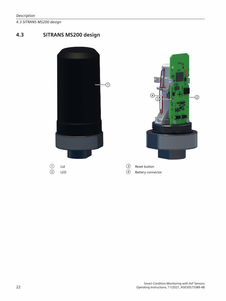
4.3 SITRANS MS200 design
① Lid ③ Reset button② LED ④ Battery connector
Description4.3 SITRANS MS200 design
Smart Condition Monitoring with IIoT Sensors22 Operating Instructions, 11/2021, A5E50573389-AB
Installing/mounting 55.1 Installation instructions SITRANS CC220
NoteInfluences on data transmissionThe positioning of the sensors and the gateway as well as the environmental conditions influence the data transmission between SITRANS MS200 and SITRANS CC220. In case of an unfavorable constellation, transmission losses may occur.
5.1.1 Mounting SITRANS CC220
Introduction• Observe the safety notes in chapter Notes on use (Page 16).• The device is approved for indoor operation only.• Install the device in cabinets, separate rooms or controlled areas. Only authorized personnel
may access the device using locks or similar measures.• Observe the relevant DIN/VDE requirements or the applicable country-specific regulations.• Install the bluetooth antenna outside the cabinet.• To install the mounting clamps and brackets, Siemens recommends you use 0.6 Nm
tightening torque.
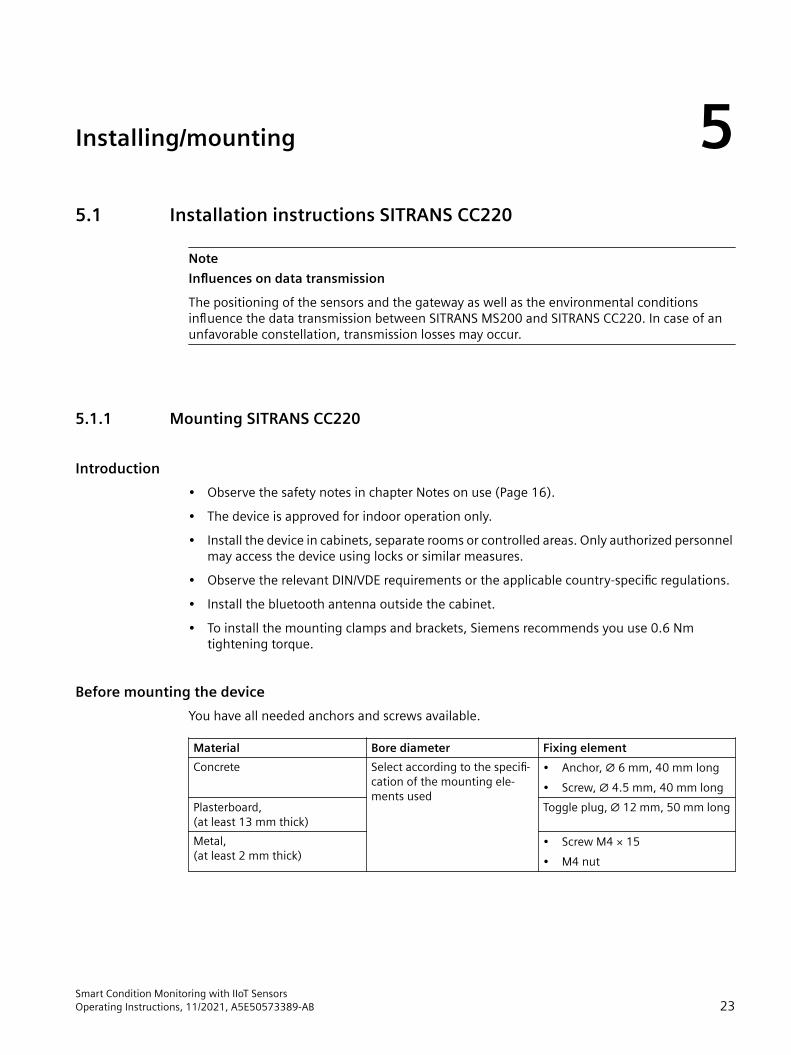
Before mounting the deviceYou have all needed anchors and screws available.
Material Bore diameter Fixing elementConcrete Select according to the specifi‐
cation of the mounting ele‐ments used
• Anchor, ∅ 6 mm, 40 mm long• Screw, ∅ 4.5 mm, 40 mm long
Plasterboard, (at least 13 mm thick)
Toggle plug, ∅ 12 mm, 50 mm long
Metal, (at least 2 mm thick)
• Screw M4 × 15• M4 nut
Smart Condition Monitoring with IIoT SensorsOperating Instructions, 11/2021, A5E50573389-AB 23

Procedure1. Mount the device on DIN rails or wall.
Mounting positions and mounting types (Page 25)Mounting on DIN rails (Page 26)Mounting on a wall (Page 27)
2. Mount the bluetooth antenna outside the cabinet.3. Mount the bluetooth antenna extension.
See technical details of the bluetooth antenna extension in chapter Technical specifications SITRANS CC220 (Page 69).
4. Bring the bluetooth antenna in a vertical position.
Mounting example in a cabinetSee technical details of the bluetooth antenna extension in chapter Technical specifications SITRANS CC220 (Page 69).
Installing/mounting5.1 Installation instructions SITRANS CC220
Smart Condition Monitoring with IIoT Sensors24 Operating Instructions, 11/2021, A5E50573389-AB

See alsoAccessories (Page 77)
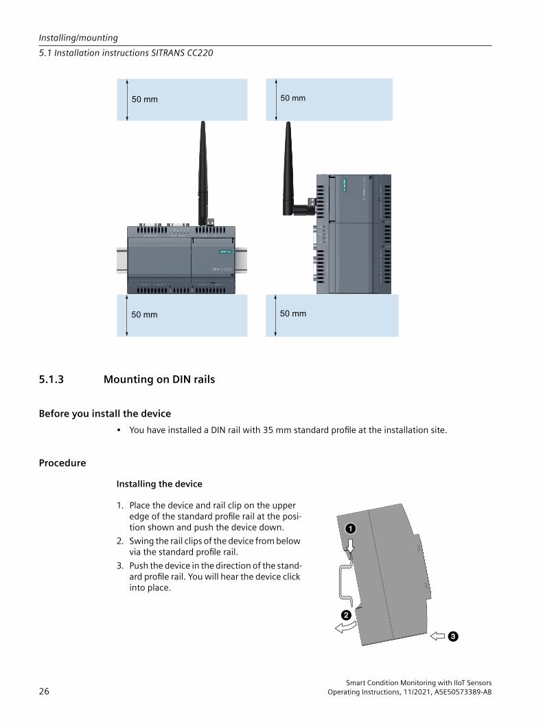
5.1.2 Mounting positions and mounting typesThe device can be mounted horizontally or vertically on a DIN rail or to a wall.
Horizontal mounting position, rec‐ommended
Vertical mounting position
Consider the permitted temperature range for operation that depends on the mounting position in accordance with the Technical specifications SITRANS CC220 (Page 69) chapter.
ClearancesEnsure that the following clearances measurements to another component or to a wall of a housing are complied with:• Below the device: ≥ 50 mm• Above the device: ≥ 50 mm
Installing/mounting5.1 Installation instructions SITRANS CC220
Smart Condition Monitoring with IIoT SensorsOperating Instructions, 11/2021, A5E50573389-AB 25
5.1.3 Mounting on DIN rails
Before you install the device• You have installed a DIN rail with 35 mm standard profile at the installation site.
ProcedureInstalling the device
1. Place the device and rail clip on the upper edge of the standard profile rail at the posi‐tion shown and push the device down.
2. Swing the rail clips of the device from below via the standard profile rail.
3. Push the device in the direction of the stand‐ard profile rail. You will hear the device click into place.
Installing/mounting5.1 Installation instructions SITRANS CC220
Smart Condition Monitoring with IIoT Sensors26 Operating Instructions, 11/2021, A5E50573389-AB
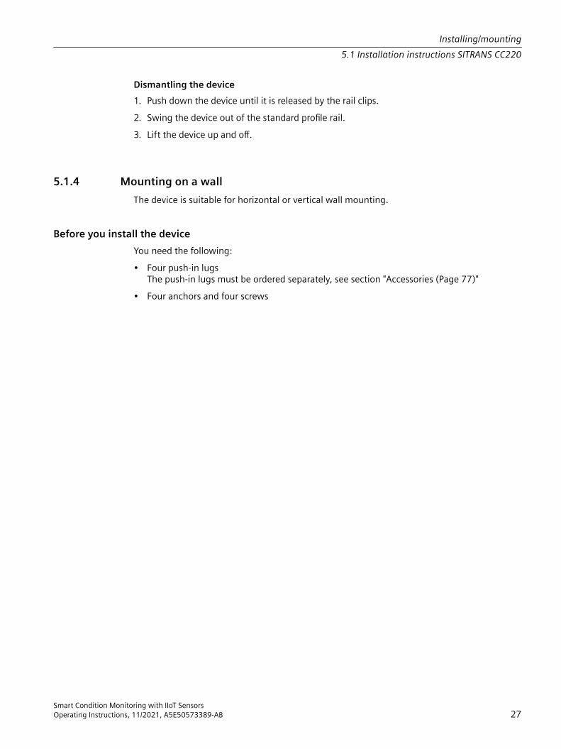
Dismantling the device1. Push down the device until it is released by the rail clips.2. Swing the device out of the standard profile rail.3. Lift the device up and off.
5.1.4 Mounting on a wallThe device is suitable for horizontal or vertical wall mounting.
Before you install the device You need the following:• Four push-in lugs
The push-in lugs must be ordered separately, see section "Accessories (Page 77)"• Four anchors and four screws
Installing/mounting5.1 Installation instructions SITRANS CC220
Smart Condition Monitoring with IIoT SensorsOperating Instructions, 11/2021, A5E50573389-AB 27

Procedure for mounting1. Guide a push-in lug
through the correspond‐ing opening at the top of the device, as shown
2. Press the push-in lug down.
3. Mark the bore holes, drill the required holes in the wall and fasten the de‐vice to the wall using four screws and corre‐sponding anchors.
5.2 Installation instructions SITRANS MS200
5.2.1 Basic safety notes SITRANS MS200
WARNINGUnsuitable connecting partsRisk of injury or poisoning. In case of improper mounting, hot, toxic, and corrosive process media could be released at the connections.• Ensure that connecting parts are suitable for connection and process media.
Installing/mounting5.2 Installation instructions SITRANS MS200
Smart Condition Monitoring with IIoT Sensors28 Operating Instructions, 11/2021, A5E50573389-AB
NoteMaterial compatibilitySiemens can provide you with support concerning selection of sensor components wetted by process media. However, you are responsible for the selection of components. Siemens accepts no liability for faults or failures resulting from incompatible materials.
CAUTIONHot surfaces resulting from hot process mediaRisk of burns resulting from surface temperatures above 65 °C (149 °F). • Take appropriate protective measures, for example contact protection.• Make sure that protective measures do not cause the maximum permissible ambient
temperature to be exceeded. Refer to the information in Technical specifications (Page 69).
NOTICECondensation in the deviceDamage to device through formation of condensation if the temperature difference between transportation or storage and the mounting location exceeds 20 °C (36 °F).• Before taking the device into operation, let the device adapt for several hours in the new
environment.
5.2.1.1 Installation location requirements
NOTICEAggressive atmospheresDamage to device through penetration of aggressive vapors.• Ensure that the device is suitable for the application.
NOTICEDirect sunlightDamage to device.The device can overheat or materials become brittle due to UV exposure.• Protect the device from direct sunlight.• Make sure that the maximum permissible ambient temperature is not exceeded. Refer to
the information in Technical specifications (Page 69).
Installing/mounting5.2 Installation instructions SITRANS MS200
Smart Condition Monitoring with IIoT SensorsOperating Instructions, 11/2021, A5E50573389-AB 29

5.2.2 General description
NOTICEWrong assemblyWrong assembly can damage the asset or the SITRANS MS200.• Carefully read the safety instructions before mounting.
SITRANS MS200 has an M8 female thread for the installation, see chapter Dimension drawings SITRANS MS200 (Page 74). For thread M8:• minimum screw-in depth 5,5 mm• maximum screw-in depth 13 mm• screw-in torque min. 18 Nm and max. 20 Nm• screw-in material stainless steelUse an anaerobic adhesive thread locker.SITRANS MS200 can be mounted in various ways utilizing its threaded M8 hole. As examples for mounting you can:• directly mount SITRANS MS200 to an existing stud bolt• use a short threaded bolt to mount SITRANS MS200 to a threaded hole• use a clamp shell to mount SITRANS MS200 to a pipeIn all cases a strong and form-fitting mount for good vibrations transmission is required.
NoteFor temporary mountings (e.g. testing purposes) you can also use a strong magnet or an industry graded glue to mount SITRANS MS200.
NoteMount SITRANS MS200 so that the lid can be easily removed in the mounted state for a later battery pack replacement (Page 58).
For more information, watch this video (https://www.youtube.com/watch?v=kHCWsAgltqE).
NoteInfluences on data transmissionThe positioning of the sensors and the gateway as well as the environmental conditions influence the data transmission between SITRANS MS200 and SITRANS CC220. In case of an unfavorable constellation, transmission losses may occur.
Installing/mounting5.2 Installation instructions SITRANS MS200
Smart Condition Monitoring with IIoT Sensors30 Operating Instructions, 11/2021, A5E50573389-AB

5.2.3 Installing SITRANS MS200 on a pump or compressorMount SITRANS MS200 near the liquid inlet directly on the pump.
NoteSITRANS MS200 must not get in direct contact with chemicals.
NOTICEMaximum specified ambient temperatureThe maximum specified ambient temperature must not be exceeded by the pump or compressor. See Technical specifications SITRANS MS200 (Page 71).
5.2.4 Installing SITRANS MS200 on a gearMount SITRANS MS200 directly on the gear. The most suitable place is at the middle of the gear in the horizontal position.
NOTICEMaximum specified ambient temperature The maximum specified ambient temperature must not be exceeded by the gear. See Technical specifications SITRANS MS200 (Page 71).
NoteSITRANS MS200 must not get in contact with gear oil or gear oil vapors.
5.2.5 Installing SITRANS MS200 on rotating or vibrating equipmentAny rotating or vibrating equipment can be supervised with SITRANS MS200. Mount SITRANS MS200 as close as possible to vibrating components.
NOTICEMaximum specified ambient temperature The maximum specified ambient temperature must not be exceeded by the rotating or vibrating equipment. See Technical specifications SITRANS MS200 (Page 71).
Installing/mounting5.2 Installation instructions SITRANS MS200
Smart Condition Monitoring with IIoT SensorsOperating Instructions, 11/2021, A5E50573389-AB 31

5.3 Disassembly SITRANS MS200
WARNINGIncorrect disassemblyIn order to disassemble correctly, observe the following:• Before starting work, make sure that you have switched off all physical variables such as
pressure, temperature, electricity etc. or that they have a harmless value.• Make sure that no environmentally hazardous media are released.• Secure the remaining connections so that no damage can result if the process is started
unintentionally.
Installing/mounting5.3 Disassembly SITRANS MS200
Smart Condition Monitoring with IIoT Sensors32 Operating Instructions, 11/2021, A5E50573389-AB
Connecting SITRANS CC220 66.1 Basic safety notes
WARNINGRisk of lightning strikesA lightning flash may enter the mains cables and data transmission cables and jump to a person.Death, serious injury and burns can be caused by lightning.Take the following precautions:• Disconnect the device from the power supply in good time when a thunderstorm is
approaching.• Do not touch mains cables and data transmission cables during a thunderstorm.• Keep an enough distance from electric cables, distributors, systems, etc.
CAUTIONUse copper cables at connectors with terminal connectionsUse copper (Cu) cables for all supply lines that are connected to the device with terminals, e.g. 24 V DC power supply cables to the 24 V DC power supply connectors.Utiliser des câbles en cuivre sur les connexions à bornesUtilisez des câbles en cuivre (Cu) pour tous les câbles d'alimentation qui sont raccordés à l'appareil par des bornes, par exemple les câbles d'alimentation 24 V CC sur le connecteur d'alimentation 24 V CC.
NoteThe device should only be connected to a 24 V DC power supply which meets the requirements of safe extra low voltage (SELV) according to IEC/EN/DIN EN/UL 61010-1.
NoteThe power supply must be adapted to the input data of the device. See chapter "Technical specifications SITRANS CC220 (Page 69)".If there are voltage peaks on power supply lines, use a protective device in the form of a varistor (MOV) UMOV = U-rated x 1.2 (BLITZDUCTOR BVT AVD 24 (918 422) or compatible).
Smart Condition Monitoring with IIoT SensorsOperating Instructions, 11/2021, A5E50573389-AB 33
NOTICECondensation in the deviceDamage to device through formation of condensation if the temperature difference between transportation or storage and the mounting location exceeds 20 °C (36 °F).• Before taking the device into operation, let the device adapt for several hours in the new
environment.
6.1.1 Improvement of interference immunity
NoteImprovement of interference immunity• Lay signal cables separate from cables with voltages > 60 V.• Use cables with twisted wires.• Keep device and cables at a distance from strong electromagnetic fields.• Take account of the conditions for communication specified in the Technical specifications
SITRANS CC220 (Page 69).• Use ethernet cables cat 5e/cat 6 to guarantee the full specification according to IEC11801
rated for 70 °C.
6.2 Connecting SITRANS CC220
Before connecting the device• You are using the supplied terminal plug.• A two-core cable meet the following requirements:
– a copper (Cu) cable with cross-section of 0.75 to 2.5 mm2
– rated temperature 70 °C• A slotted screwdriver with a 3 mm blade.
Connecting SITRANS CC2206.2 Connecting SITRANS CC220
Smart Condition Monitoring with IIoT Sensors34 Operating Instructions, 11/2021, A5E50573389-AB
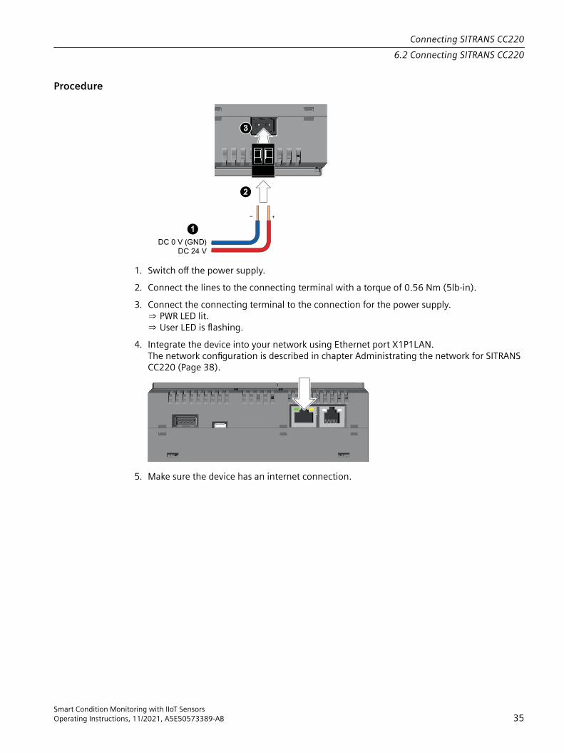
Procedure
1. Switch off the power supply.2. Connect the lines to the connecting terminal with a torque of 0.56 Nm (5lb-in).3. Connect the connecting terminal to the connection for the power supply.
⇒ PWR LED lit.⇒ User LED is flashing.
4. Integrate the device into your network using Ethernet port X1P1LAN.The network configuration is described in chapter Administrating the network for SITRANS CC220 (Page 38).
5. Make sure the device has an internet connection.
Connecting SITRANS CC2206.2 Connecting SITRANS CC220
Smart Condition Monitoring with IIoT SensorsOperating Instructions, 11/2021, A5E50573389-AB 35

Connecting SITRANS CC2206.2 Connecting SITRANS CC220
Smart Condition Monitoring with IIoT Sensors36 Operating Instructions, 11/2021, A5E50573389-AB

Commissioning 77.1 Basic safety notes
WARNINGCommissioning and operation with pending errorIf an error message appears, correct operation in the process is no longer guaranteed.• Check the gravity of the error.• Correct the error.• If the error still exists:
– Take the device out of operation.– Prevent renewed commissioning.
WARNINGHot surfacesRisk of burns resulting from hot surfaces.• Take corresponding protective measures, for example by wearing protective gloves.
7.2 Starting SITRANS SCM IQ in MindSphere
Required user roles:• MindSphere user role: TenantAdmin or assetmanager.admin
Procedure1. Start SITRANS SCM IQ in MindSphere as an admin the very first time after provisioning.
⇒ SITRANS SCM IQ opens with the initial dialog.2. Confirm the dialog.
The following objects will be created automatically:– MindSphere Agent: SitransMS Connector– MindSphere Asset Type: SitransMSYou need to perform this task only the very first time after launching SITRANS SCM IQ to MindSphere. You do not need to repeat this task at a later stage.
Smart Condition Monitoring with IIoT SensorsOperating Instructions, 11/2021, A5E50573389-AB 37

7.3 Administrating the network for SITRANS CC220
Required user roleNetwork administrator of your side.
Procedure1. Consider the choice of your network settings in SITRANS SCM IQ (Page 41) according to your
network policies ("DHCP" or "Static IP").2. Make sure the UDP port 123 is accessible in the network.
SITRANS CC220 is using Siemens NTP server pool: {0..3}.siemens.pool.ntp.org. NTP time synchronization is using UDP port 123.
7.4 Powering up SITRANS MS200
WARNINGRemoving the lid in a dirty environmentDo not remove the lid in a dirty environment, as contamination of internal components could reduce battery life.• Remove the lid only in an environment of approximately 25 °C (77 °F) and 30-60% RH.
WARNINGElectrostatic discharge• Prevent grease or other contaminants from touching PCB, as this could reduce battery life.• Avoid direct skin contact with PCB.
Commissioning7.4 Powering up SITRANS MS200
Smart Condition Monitoring with IIoT Sensors38 Operating Instructions, 11/2021, A5E50573389-AB

1. Unscrew the sensor lid: Hold with an open-ended wrench at ② and turn the lid ① counterclockwise.
2. Connect the battery connector ④ to the PCB.⇒ The LED ③ placed on the PCB lights up for one second after the boot process is completed (up to 10 seconds).
Commissioning7.4 Powering up SITRANS MS200
Smart Condition Monitoring with IIoT SensorsOperating Instructions, 11/2021, A5E50573389-AB 39

3. Open the grease blister and grease the base plate.CAUTION
Grease on electrical partsAvoid getting grease on electrical components and PCB.
Synthet
ic Greas
e
4. Screw on the lid to 6-7 Nm per hand.5. Mount the SITRANS MS200 onto the asset, using a wrench (min. 18 Nm/max. 20 Nm).Now SITRANS MS200 is active and can be connected wirelessly to SITRANS CC220 via Bluetooth® low energy (BLE). If SITRANS SCM IQ and SITRANS CC220 are configured and SITRANS MS200 is in range, SITRANS MS200 will connect automatically.
7.5 Integrating SITRANS MS200 to MindSphere Asset ManagerEach SITRANS MS200 to be connected to MindSphere will be mapped to a MindSphere Asset as a digital representation. Assets are created in the MindSphere Asset Manager. For more details refer to MindSphere manual (https://siemens.mindsphere.io/en/docs/mindaccess.html).For more information, watch this video (https://www.youtube.com/watch?v=AJLLbYmtN2A&t=36s).
Required user roles• MindSphere user role: Assetmanager.admin or TenantAdmin
Procedure1. Start Asset Manager in MindSphere.2. Navigate to "Assets".
Commissioning7.5 Integrating SITRANS MS200 to MindSphere Asset Manager
Smart Condition Monitoring with IIoT Sensors40 Operating Instructions, 11/2021, A5E50573389-AB
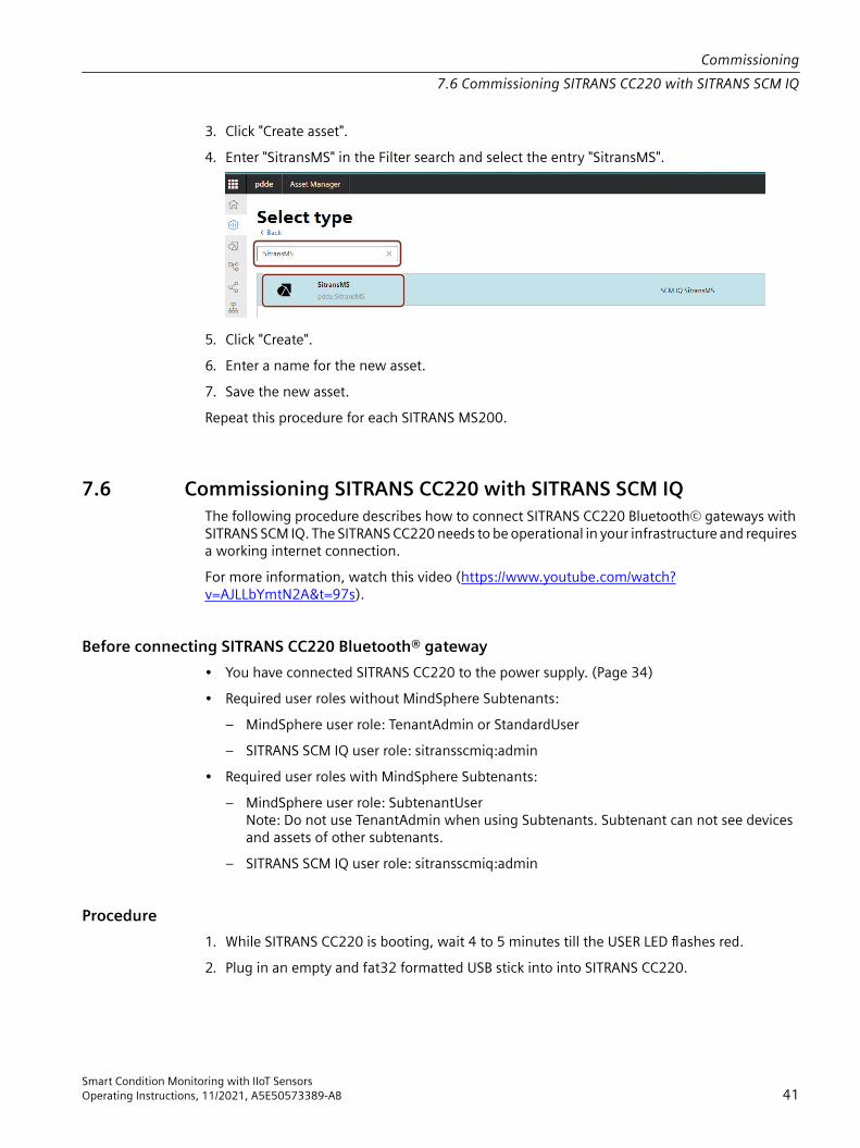
3. Click "Create asset".4. Enter "SitransMS" in the Filter search and select the entry "SitransMS".
5. Click "Create".6. Enter a name for the new asset.7. Save the new asset.Repeat this procedure for each SITRANS MS200.
7.6 Commissioning SITRANS CC220 with SITRANS SCM IQThe following procedure describes how to connect SITRANS CC220 Bluetooth© gateways with SITRANS SCM IQ. The SITRANS CC220 needs to be operational in your infrastructure and requires a working internet connection.For more information, watch this video (https://www.youtube.com/watch?v=AJLLbYmtN2A&t=97s).
Before connecting SITRANS CC220 Bluetooth® gateway• You have connected SITRANS CC220 to the power supply. (Page 34)• Required user roles without MindSphere Subtenants:
– MindSphere user role: TenantAdmin or StandardUser– SITRANS SCM IQ user role: sitransscmiq:admin
• Required user roles with MindSphere Subtenants:– MindSphere user role: SubtenantUser
Note: Do not use TenantAdmin when using Subtenants. Subtenant can not see devices and assets of other subtenants.
– SITRANS SCM IQ user role: sitransscmiq:admin
Procedure1. While SITRANS CC220 is booting, wait 4 to 5 minutes till the USER LED flashes red.2. Plug in an empty and fat32 formatted USB stick into into SITRANS CC220.
Commissioning7.6 Commissioning SITRANS CC220 with SITRANS SCM IQ
Smart Condition Monitoring with IIoT SensorsOperating Instructions, 11/2021, A5E50573389-AB 41

3. For USB stick specifications see chapter Technical specifications SITRANS CC220 (Page 69).
⇒ SITRANS CC220 generates and saves the public key to the USB stick. The public key will be used later to encrypt the integration information for SITRANS CC220.
4. Wait until the USER LED is flashing orange (may take several minutes).5. Remove the USB stick.6. Note the MAC address from the SITRANS CC220 nameplate.7. Plug the USB stick in your PC.8. Start SITRANS SCM IQ in MindSphere.9. Navigate to the "Device configuration" tab.
10.Click "Connect device".11.Select "Connect a new gateway" and click "Next".12.Enter a name and the MAC address for the gateway. You find the MAC address on the
SITRANS CC220 nameplate.13.Select the public key from the USB stick.
⇒ The public key will be loaded from the USB stick.14.Select one connection setting: "DHCP" or "Static IP".
See also chapter Administrating the network for SITRANS CC220 (Page 38).15.Select and enter your local network connection settings and click "Save".
⇒ The onboarding key is generated and available in the download folder set in your browser settings.⇒ LAN interface X1P1LAN of SITRANS CC220 will be configured according to the connection settings.
16.Move the generated onboarding key to the USB stick.Info: Store the onboarding key on the same level right next to the public key of SITRANS CC220.Don't delete files from the USB stick.
17.Plug the USB stick with the onboarding key again into the USB Port of the SITRANS CC220.18.Wait until the USER LED is indicating green (may take several minutes).
⇒ The onboarding key has been decrypted successfully.
Commissioning7.6 Commissioning SITRANS CC220 with SITRANS SCM IQ
Smart Condition Monitoring with IIoT Sensors42 Operating Instructions, 11/2021, A5E50573389-AB

19.Remove the USB stick.20.Check the operating state of SITRANS CC220 in SITRANS SCM IQ in the "Device
configuration" tab:– green: connected– yellow: connection in progress– red: disconnectedIt may take several minutes for the operating state to show in SITRANS SCM IQ.
Repeat this procedure for each SITRANS CC220.
7.7 Commissioning SITRANS MS200 with SITRANS SCM IQThe following procedure describes how to connect SITRANS MS200 sensors with SITRANS SCM IQ. Each SITRANS MS200 needs to be assigned to a SITRANS CC220 gateway and mapped to a specific Asset in the Asset structure in MindSphere (see Integrating SITRANS MS200 to MindSphere Asset Manager (Page 40)). For more information, watch this video (https://www.youtube.com/watch?v=AJLLbYmtN2A&t=258s).
Required user roles• Required user roles without MindSphere Subtenants:
– MindSphere user role: TenantAdmin or StandardUser– SITRANS SCM IQ user role: sitransscmiq:admin
• Required user roles with MindSphere Subtenants:– MindSphere user role: SubtenantUser
Note: Do not use TenantAdmin when using Subtenants. Subtenant can not see devices and assets of other subtenants.
– SITRANS SCM IQ user role: sitransscmiq:admin
Commissioning7.7 Commissioning SITRANS MS200 with SITRANS SCM IQ
Smart Condition Monitoring with IIoT SensorsOperating Instructions, 11/2021, A5E50573389-AB 43

Procedure1. Start SITRANS SCM IQ in MindSphere.2. Navigate to the "Device configuration" tab.
3. Click "Connect device" or "Add sensors" on an existing gateway.4. Select "Connect a new sensor" and choose an existing gateway from the drop-down menu.5. Click "Next".6. Enter a name and the MAC address for the sensor. You can find the MAC address on the
SITRANS MS200 nameplate.7. To map the SITRANS MS200 to an asset in the MindSphere Asset Structure, click on "Browse"
at "Asset and position".8. Choose an asset and enter additional information on the sensor position.9. Click "Save".
ResultSITRANS MS200 will now be automatically assigned to the SITRANS CC220 and transfer data to the chosen Asset of Asset type SITRANS MS200.
7.8 Configuring notificationsConfigured users will receive notifications when an anomaly is detected by the application. To configure the anomaly detection model please refer to Training anomaly detection models (Page 47).For more information, watch this video (https://www.youtube.com/watch?v=AJLLbYmtN2A&t=352s).
Commissioning7.8 Configuring notifications
Smart Condition Monitoring with IIoT Sensors44 Operating Instructions, 11/2021, A5E50573389-AB
Required user roles• Required user roles without MindSphere Subtenats:
– MindSphere user role: TenantAdmin or StandardUser– SITRANS SCM IQ user role: sitransscmiq:admin
• Required user roles with MindSphere Subtenats:– MindSphere user role: SubtenatUser
Note: Do not use TenantAdmin when using Subtenants. Subtenant can not see devices and assets of other subtenants.
– SITRANS SCM IQ user role: sitransscmiq:admin
Procedure1. Navigate to the "Notification configuration" tab.2. Click "Add user".3. Enter the required details and click "Save".4. In the "Notification configuration", click "User groups".5. Click "Add user group".6. Enter the details for the user group and select the users that shall be assigned to this group.7. Select the type of notification (SMS and/or e-mail).8. For e-mail notifications additional options can be configured.9. Click "Save".
Commissioning7.8 Configuring notifications
Smart Condition Monitoring with IIoT SensorsOperating Instructions, 11/2021, A5E50573389-AB 45

Commissioning7.8 Configuring notifications
Smart Condition Monitoring with IIoT Sensors46 Operating Instructions, 11/2021, A5E50573389-AB
Operating 88.1 Training anomaly detection models
Once SITRANS MS200 has collected a sufficient amount of data (typically two weeks), you can continue with the training of an anomaly detection model. After the trained model is available you can start the model for continuous anomaly detection.For more information, watch this video (https://www.youtube.com/watch?v=i5Khz0MKO68).
Required user roles• Required user roles without MindSphere Subtenants:
– MindSphere user role: TenantAdmin or StandardUser– SITRANS SCM IQ user role: sitransscmiq:admin
• Required user roles with MindSphere Subtenants:– MindSphere user role: SubtenantUser
Note: Do not use TenantAdmin when using Subtenants. Subtenant can not see devices and assets of other subtenants.
– SITRANS SCM IQ user role: sitransscmiq:admin
Procedure1. Navigate to the "Sensor data modelling" tab.2. Select an available asset to get further information.3. To view the sensor data, click "See details".
You can change the visible time range and select one or more variables for a more detailed view.
Smart Condition Monitoring with IIoT SensorsOperating Instructions, 11/2021, A5E50573389-AB 47

4. Click "Train new model".
5. Enter a name for the anomaly detection model and an optional description.6. Select the data which will be considered for the anomaly detection model. Multiple time
ranges can be selected.7. Save draft and train later or save and start training. The trained anomaly detection model will
be available for selection here after a few minutes:
8. To start the continuous detection of anomalies, click "Run model".The status indicates the current step of processing the data. Available statuses:– Draft– ReadyForTraining, PreparingForTraining, PreparingFailed– Training– TrainingFailed, ReadyForDeployment, Deployed– DeploymentFailed
NoteEditing an anomaly detection modelAfter an anomaly detection model has been edited, the model must be trained again.
Operating8.1 Training anomaly detection models
Smart Condition Monitoring with IIoT Sensors48 Operating Instructions, 11/2021, A5E50573389-AB
ResultAfter deploying an anomaly detection model, anomalies are automatically detected when they occur.You can manage the anomalies in the SITRANS Anomaly IQ app provided in your MindSphere Tenant.
8.2 Managing anomalies in SITRANS Anomaly IQIf you deployed an anomaly detection model in SITRANS SCM IQ, you find all detected anomalies in the SITRANS Anomaly IQ app. No further configuration is necessary to use SITRANS Anomaly IQ. You can enter information relevant to solve anomalies. This information is available as a documentation for later use or to share the information with other users that have access to your application.For more information, watch this video (https://www.youtube.com/watch?v=uF5K5ergtQk).
User roles in SITRANS Anomaly IQ• maintenance worker: editing anomalies and setting anomalies to "Done"• team lead: reviewing labels and setting anomalies to "Resolved"
Procedure1. Launch SITRANS Anomaly IQ.
You can see all open anomalies in the "Open" tab.2. To enter details, click on an anomaly.
You can attach additional files (for example photos, videos, manuals). Be aware that this consumes MindSphere Ressource IoT file storage. You can upgrade this storage if required.
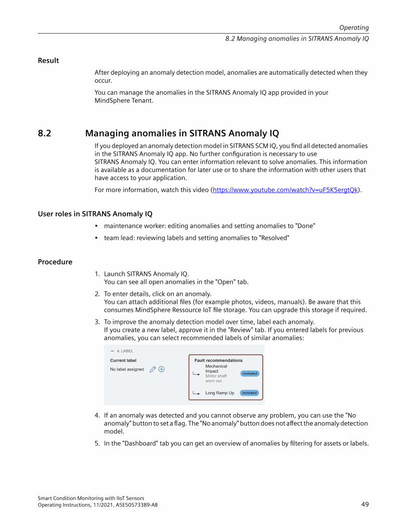
3. To improve the anomaly detection model over time, label each anomaly.If you create a new label, approve it in the "Review" tab. If you entered labels for previous anomalies, you can select recommended labels of similar anomalies:
4. If an anomaly was detected and you cannot observe any problem, you can use the "No anomaly" button to set a flag. The "No anomaly" button does not affect the anomaly detection model.
5. In the "Dashboard" tab you can get an overview of anomalies by filtering for assets or labels.
Operating8.2 Managing anomalies in SITRANS Anomaly IQ
Smart Condition Monitoring with IIoT SensorsOperating Instructions, 11/2021, A5E50573389-AB 49

8.3 Disconnecting SITRANS CC220 and SITRANS MS200
Required user roles• MindSphere user role: TenantAdmin or StandardUser• SITRANS SCM IQ user role: sitransscmiq:admin
Procedure
WARNINGDisconnecting SITRANS MS200 with anomaly detection modelsDo not disconnect a SITRANS MS200 which has a running anomaly detection model in SITRANS SCM IQ. Before you disconnect any SITRANS MS200, make sure to stop running anomaly detection models of this SITRANS MS200.
1. Navigate to the "Device configuration" tab.2. Click "Disconnect gateway/sensor" in the context menu of the respective SITRANS CC220 or
SITRANS MS200.3. To complete the offboading of SITRANS CC220, press the USER button on the SITRANS CC220
for more than 5 seconds.NoteConsequencesIf you disconnect a SITRANS CC220, observe the following consequences:• connection to SITRANS CC220 gets lost• SITRANS CC220 is removed from device list in SITRANS SCM IQ • SITRANS MS200 paired with this SITRANS CC220 are removed from sensor list• timeseries data on assets will be kept in MindSphere but not updated anymoreIf you disconnect a SITRANS MS200, observe the following consequences:• SITRANS MS200 is removed from device list in SITRANS SCM IQ• connection between SITRANS MS200 and SITRANS CC220 gets lost (SITRANS CC220
remains in the device list in SITRANS SCM IQ)• timeseries data on assets will be kept in MindSphere but not updated anymore
See alsoResetting or disconnecting SITRANS CC220 from SITRANS SCM IQ (Offboarding) (Page 51)
Operating8.3 Disconnecting SITRANS CC220 and SITRANS MS200
Smart Condition Monitoring with IIoT Sensors50 Operating Instructions, 11/2021, A5E50573389-AB

8.4 Resetting or disconnecting SITRANS CC220 from SITRANS SCM IQ (Offboarding)
• Press the USER button on the SITRANS CC220 for more than 5 seconds.⇒ The USER LED lights up red.⇒ SITRANS CC220 has no established connection to SITRANS SCM IQ.⇒ SITRANS CC220 is reset to factory settings.
8.5 Resetting SITRANS MS200If you disconnected SITRANS MS200 in SITRANS SCM IQ and want to connect it again under another SITRANS CC220 gateway, push the reset button on the SITRANS MS200 for more than 2 seconds.
Operating8.5 Resetting SITRANS MS200
Smart Condition Monitoring with IIoT SensorsOperating Instructions, 11/2021, A5E50573389-AB 51

8.6 Accessing the OSS Readme and source codeThe OSS Readme and source code is available:• in SIOS:
– SITRANS CC220 (https://support.industry.siemens.com/cs/de/en/ps/28809/man)– SITRANS MS200 (https://support.industry.siemens.com/cs/de/en/ps/28810/man)
• in SITRANS SCM IQ in the "OS Bar"• on the root of the SD card delivered with the SITRANS CC220 gateway
Operating8.6 Accessing the OSS Readme and source code
Smart Condition Monitoring with IIoT Sensors52 Operating Instructions, 11/2021, A5E50573389-AB

Service and maintenance 99.1 Maintenance and repair work for SITRANS CC220
9.1.1 Basic safety notes
NoteThe device is maintenance-free. However to retain a high level of system availability, we recommend the preventative replacement of the back-up battery at replacement intervals of 5 years.
WARNINGImpermissible repair and maintenance of the device• Repair and maintenance must be carried out by Siemens authorized personnel only.
CAUTIONHazardous voltage at open deviceRisk of electric shock when the enclosure is opened or enclosure parts are removed.• Before you open the enclosure or remove enclosure parts, de-energize the device.• If maintenance measures in an energized state are necessary, observe the particular
precautionary measures. Have maintenance work carried out by qualified personnel.
Smart Condition Monitoring with IIoT SensorsOperating Instructions, 11/2021, A5E50573389-AB 53

9.1.1.1 Repair information
Carrying out repairs Only qualified personnel are permitted to repair the device. Contact your local representative. See section "Technical support (Page 76)".
WARNINGUnauthorized opening and improper repairs on the device may result in substantial damage to equipment or endanger the user.• Always disconnect the power plug before you open the device.• Only install system expansion devices designed for this device. If you install other expansion
devices, you may damage the device or violate the safety requirements and regulations on RF suppression. Contact your technical support team or where you purchased your PC to find out which system expansion devices may safely be installed.
If you install or exchange system expansions and damage your device, the warranty becomes void.
CAUTIONElectrostatic sensitive devices (ESD)The device contains electronic components which are destroyed by electrostatic charges. This can result in malfunctions and damage to the machine or plant.Make sure you take precautionary measures even when you open the device, for example, when opening device doors, device covers or the housing cover. For more information, refer to the ESD Guideline.
Limitation of liability All technical specifications and approvals of the device only apply if you use expansion components that have a valid CE approval (CE mark). The installation instructions for expansion components in the associated documentation must be observed.UL approval of the device only applies when the UL-approved components are used according to their "Conditions of Acceptability".We are not liable for functional limitations caused by using third-party devices or components.
9.1.2 Sending the log files to technical support
IntroductionFor diagnostics you can export the SITRANS CC220 log files to a USB stick.
Service and maintenance9.1 Maintenance and repair work for SITRANS CC220
Smart Condition Monitoring with IIoT Sensors54 Operating Instructions, 11/2021, A5E50573389-AB

Procedure1. Plug in an empty and fat32 formatted USB stick into your PC.
For USB stick specifications see cahpter Technical specifications SITRANS CC220 (Page 69).2. Create a file named “ConBox_Commands.json” directly on the USB stick.3. Open the “ConBox_Commands.json” file in a text editor.4. Enter the following USB command:
{ "Commands": [ { "Cmd":"CopyArchivedLogsToUsbStick", "DeleteAfterCopy":"false" } ]}
5. Save the changes to the "ConBox_Commands.json".6. Plug your USB stick into the USB Port of SITRANS CC220.
⇒ If the log file is big, the USER LED flashes slowly orange while the log files are been copied to the USB stick.If the log file is very small, the copy process is short and the LED flashing will not be seen. The log file is small, if you have recorded half a day.
7. Remove the USB stick from SITRANS CC220.8. Send the log files to the Technical support (Page 76).9. Before you establish a connection of SITRANS CC220 to SITRANS SCM IQ again (Onboarding),
remove the "ConBox_Commands.json" file from the USB stick.
See alsoMeaning of the LED states on SITRANS CC220 (Page 67)
Service and maintenance9.1 Maintenance and repair work for SITRANS CC220
Smart Condition Monitoring with IIoT SensorsOperating Instructions, 11/2021, A5E50573389-AB 55

9.1.3 Replacing the backup battery
WARNINGRisk of explosion and release of harmful substancesImproper handling of lithium batteries can result in an explosion of the batteries. Explosion of the batteries and the released pollutants can cause severe physical injury. Worn batteries jeopardize the function of the device.Note the following when handling lithium batteries:• Replace the battery every 5 years.• Replace the lithium battery only with the type recommended by the manufacturer.
The article number is A5E34734290.• Do not throw lithium batteries into fire, do not solder on the cell body, do not recharge, do
not open, do not short-circuit, do not reverse polarity, do not heat above 100°C and protect from direct sunlight, moisture and condensation.
NOTICEDisposal of batteries and rechargeable batteriesBatteries and rechargeable batteries do not belong in domestic garbage. The user is legally obliged to return used batteries and rechargeable batteries.Used batteries and rechargeable batteries pollute the environment as special waste. You as a user are liable to prosecution if you do not properly dispose of batteries and rechargeable batteries.Please observe the following when disposing of batteries and rechargeable batteries:• Dispose of used batteries and rechargeable batteries separately as hazardous waste in
accordance with local regulations.• You can return used batteries and rechargeable batteries to public collection points and
wherever batteries or rechargeable batteries of the type in question are sold.• Label the battery container "Used batteries and rechargeable batteries".
Requirement • The device is disconnected from the power supply.• A replacement battery with the article number A5E34345932 is available.
Service and maintenance9.1 Maintenance and repair work for SITRANS CC220
Smart Condition Monitoring with IIoT Sensors56 Operating Instructions, 11/2021, A5E50573389-AB

ProcedureAs soon as the device has an internet connection, time will be set by NTP. See chapter Administrating the network for SITRANS CC220 (Page 38).
1. Open the cover on the right.2. Pull the plug of the battery cable
from the motherboard.3. Remove the battery from the bat‐
tery box.Insert the replacement battery, plug in the battery cable on the mother‐board and close the cover on the right.
9.1.4 Replacing SITRANS CC220
Replacing a defective SITRANS CC2201. Stop anomaly detection models of the SITRANS MS200 assigned to the defective SITRANS
CC220.2. Replace defective SITRANS CC220 with new SITRANS CC220.3. Disconnect defective SITRANS CC220 in SITRANS SCM IQ.4. Connect new SITRANS CC220.5. Reconnect old SITRANS MS200 with SITRANS SCM IQ to the same MindSphere asset.6. Reset SITRANS MS200.
Resetting SITRANS MS200 (Page 51)
9.2 Maintenance and repair work for SITRANS MS200
9.2.1 Basic safety notesThe device is maintenance-free. However, a periodic inspection according to pertinent directives and regulations must be carried out.
Service and maintenance9.2 Maintenance and repair work for SITRANS MS200
Smart Condition Monitoring with IIoT SensorsOperating Instructions, 11/2021, A5E50573389-AB 57

An inspection can include, for example, check of:• Ambient conditions• Seal integrity of the cover
NOTICEPenetration of moisture into the deviceDamage to device.• Make sure when carrying out cleaning and maintenance work that no moisture penetrates
the inside of the device.
9.2.2 Replacing SITRANS MS200 battery pack
WARNINGCorrosive substancesRisk of injury. If the battery pack is damaged or leaking toxic gases and liquids can be released.The battery pack contains corrosive substances that result in burns on unprotected skin. • Wear gloves.• If contact with the corrosive substances occurs, rinse the affected skin immediately with
large amount of water to dilute substance.
CAUTIONContamination of PCBWear gloves to prevent contamination of PCB. Do not touch the PCB.
NoteIf SITRANS MS200 must be disassembled for battery replacement, observe the following:After a battery change SITRANS MS200 must be mounted again with the same angle of rotation. On the metal are two flattenings (wrench size = 44mm), which ensure the correct direction. The label gives the correct position for SITRANS MS200, 0° or 180°. If you mount SITRANS MS200 again ensure that the orientation is identical as before exchange (max. 5° angle difference).
NoteBattery temperature for replacementThe temperature difference between the new battery and the battery to be replaced should not exceed +/-5 °C.
Service and maintenance9.2 Maintenance and repair work for SITRANS MS200
Smart Condition Monitoring with IIoT Sensors58 Operating Instructions, 11/2021, A5E50573389-AB
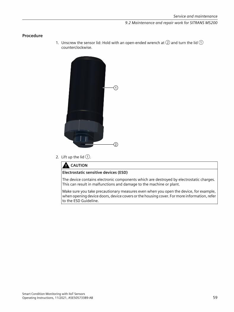
Procedure1. Unscrew the sensor lid: Hold with an open-ended wrench at ② and turn the lid ①
counterclockwise.
2. Lift up the lid ①.CAUTION
Electrostatic sensitive devices (ESD)The device contains electronic components which are destroyed by electrostatic charges. This can result in malfunctions and damage to the machine or plant.Make sure you take precautionary measures even when you open the device, for example, when opening device doors, device covers or the housing cover. For more information, refer to the ESD Guideline.
Service and maintenance9.2 Maintenance and repair work for SITRANS MS200
Smart Condition Monitoring with IIoT SensorsOperating Instructions, 11/2021, A5E50573389-AB 59
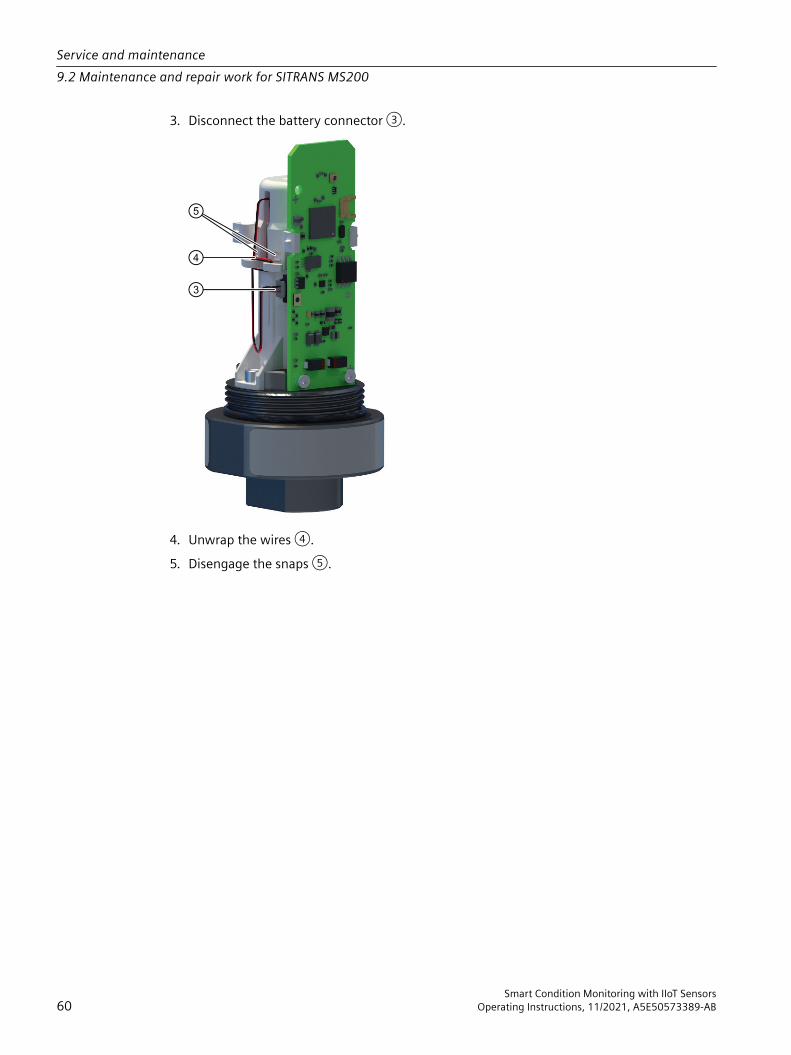
3. Disconnect the battery connector ③.
4. Unwrap the wires ④.5. Disengage the snaps ⑤.
Service and maintenance9.2 Maintenance and repair work for SITRANS MS200
Smart Condition Monitoring with IIoT Sensors60 Operating Instructions, 11/2021, A5E50573389-AB
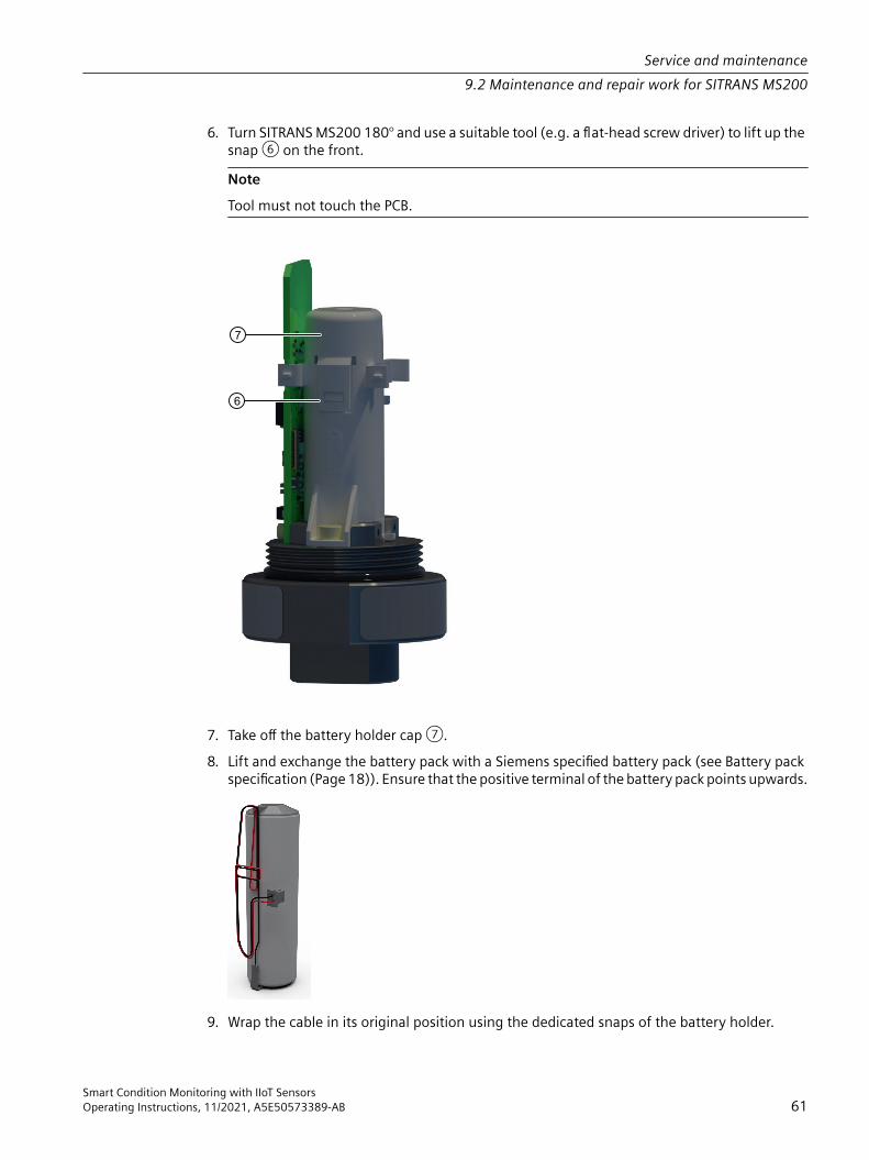
6. Turn SITRANS MS200 180° and use a suitable tool (e.g. a flat-head screw driver) to lift up the snap ⑥ on the front. NoteTool must not touch the PCB.
7. Take off the battery holder cap ⑦.8. Lift and exchange the battery pack with a Siemens specified battery pack (see Battery pack
specification (Page 18)). Ensure that the positive terminal of the battery pack points upwards.
9. Wrap the cable in its original position using the dedicated snaps of the battery holder.
Service and maintenance9.2 Maintenance and repair work for SITRANS MS200
Smart Condition Monitoring with IIoT SensorsOperating Instructions, 11/2021, A5E50573389-AB 61

10.Put the battery holder cap ⑦ back on. Ensure that the battery holder cap is correctly snapped in.
11.Connect the battery connector ③.⇒ The LED placed on the PCBA lights up for one second.
12.Place the lid ① on SITRANS MS200 and screw it on to 6-7 Nm per hand.SITRANS MS200 is now active again.
9.2.3 Replacing SITRANS MS200
WARNINGHumid environment• If working on an energized device is necessary, ensure that the environment is dry.• Make sure when carrying out cleaning and maintenance work that no moisture penetrates
the inside of the device.
CAUTIONHot surfacesRisk of burns during maintenance work on parts having surface temperatures exceeding 65 °C (149 °F). • Take corresponding protective measures, for example by wearing protective gloves.• After carrying out maintenance, remount touch protection measures.
Replacing a defective SITRANS MS2001. Stop anomaly detection models of the respective SITRANS MS200.2. Replace defective SITRANS MS200 with new SITRANS MS200.3. Make sure new SITRANS MS200 is powered up.4. Disconnect defective SITRANS MS200 in SITRANS SCM IQ.5. Connect new SITRANS MS200 with SITRANS SCM IQ and assign sensor to existing
MindSphere asset.For detailed description see Commissioning SITRANS MS200 with SITRANS SCM IQ (Page 43).
6. Train new anomaly detection model based on new SITRANS MS200 data.
Repositioning SITRANS MS200 on the same machine
NoteIn this scenario SITRANS CC220 and MindSphere asset remain the same.
Service and maintenance9.2 Maintenance and repair work for SITRANS MS200
Smart Condition Monitoring with IIoT Sensors62 Operating Instructions, 11/2021, A5E50573389-AB

1. Stop anomaly detection models of the respective SITRANS MS200.2. Reposition SITRANS MS200.3. Make sure SITRANS MS200 is powered up.4. Delete machine learning models based on old data from asset (if existing) by clicking on
"Sensor data modelling" > click on your sensor > "See details".5. Train new anomaly detection model only based on new data.
Moving SITRANS MS200 to another machine or repositioning on the same machine (different MindSphere asset)
NoteIn this scenario SITRANS CC220 remains the same and MindSphere changes.
1. Stop anomaly detection models of the respective SITRANS MS200.2. Reposition SITRANS MS200.3. Make sure SITRANS MS200 is powered up.4. Change assignment to MindSphere asset of SITRANS MS200 in SITRANS SCM IQ by clicking
on "Device configuration > > Configure sensor".5. Delete anomaly detection models based on old data from asset (if existing) by clicking on
"Sensor data modelling" > click on your sensor > "See details".6. Train new anomaly detection model model only based on new data.
Connecting SITRANS MS200 to another SITRANS CC220 (no repositioning)
NoteIn this scenario the physical asset and the MindSphere asset remain the same.
1. Make sure that selected SITRANS CC220 is connected in SITRANS SCM IQ.2. Change assignment of SITRANS MS200 in SITRANS SCM IQ to another SITRANS CC220 by
clicking on "Device configuration > > Configure sensor".3. Reset SITRANS MS200.
Resetting SITRANS MS200 (Page 51)
Connecting SITRANS MS200 to another MindSphere asset (no repositioning)
NoteIn this scenario the physical asset and the SITRANS CC220 remain the same.
Service and maintenance9.2 Maintenance and repair work for SITRANS MS200
Smart Condition Monitoring with IIoT SensorsOperating Instructions, 11/2021, A5E50573389-AB 63

1. Stop anomaly detection models of the respective SITRANS MS200.2. Change assignment to MindSphere asset of SITRANS MS200 in SITRANS SCM IQ by clicking
on "Device configuration > > Configure sensor".3. Delete machine learning models based on old data from asset (if existing) by clicking on
"Sensor data modelling" > click on your sensor > "See details".4. Train new anomaly detection model model only based on new data.
Moving SITRANS MS200 to another machine (different MindSphere asset, different SITRANS CC220)
NoteIn this scenario the already used SITRANS MS200 is utilized to monitor a different physical asset.
1. Stop anomaly detection models of the respective SITRANS MS200.2. Reposition SITRANS MS200.3. Make sure SITRANS MS200 is powered up.4. Reset SITRANS MS200.
Resetting SITRANS MS200 (Page 51)5. Change assignment to gateway and MindSphere asset of SITRANS MS200 in SITRANS SCM IQ
by clicking on "Device configuration > > Configure sensor".6. Delete anomaly detection models based on old data from asset (if existing) by clicking on
"Sensor data modelling" > click on your sensor > "See details".7. Train new anomaly detection model only based on new data.
9.3 Cleaning
Cleaning the enclosure• Clean the outside of the enclosure with the inscriptions using a cloth moistened with water
or a mild detergent.• Do not use any aggressive cleansing agents or solvents, e.g. acetone. Plastic parts could be
damaged. The inscriptions could become unreadable.
NOTICETransport with fitted batteryIf the battery is still present in the device when transporting, it could become loose as a result of vibrations and cause damage within the device.• Remove the batteries before returning the device.• Dispose of the batteries according to regulations or include them separately in the return
consignment.
Service and maintenance9.3 Cleaning
Smart Condition Monitoring with IIoT Sensors64 Operating Instructions, 11/2021, A5E50573389-AB

9.4 Return procedureTo return a product to Siemens, see Returns to Siemens (https://support.industry.siemens.com/cs/ww/en/sc/3098).Contact your Siemens representative to clarify if a product is repairable, and how to return it. They can also help with quick repair processing, a repair cost estimate, or a repair report/cause of failure report.
NOTICEDecontaminationThe product may have to be decontaminated before it is returned. Your Siemens contact person will let you know for which products this is required.
NoteReturn of products with lithium batteries Lithium batteries are dangerous goods according to the Regulation of Dangerous Goods, UN 3090 and UN 3091. • Remove lithium batteries prior to shipment.
9.5 DisposalDevices described in this manual should be recycled. They may not be dis‐posed of in the municipal waste disposal services according to the Directive 2012/19/EC on waste electronic and electrical equipment (WEEE).Devices can be returned to the supplier within the EC and UK, or to a locally approved disposal service for eco-friendly recycling. Observe the specific regulations valid in your country.Further information about devices containing batteries can be found at: Information about battery / product return (WEEE) (https://support.industry.siemens.com/cs/document/109479891/)
NoteSpecial disposal requiredThe device includes components that require special disposal.• Dispose of the device properly and environmentally through a local waste disposal
contractor.
Service and maintenance9.5 Disposal
Smart Condition Monitoring with IIoT SensorsOperating Instructions, 11/2021, A5E50573389-AB 65

Service and maintenance9.5 Disposal
Smart Condition Monitoring with IIoT Sensors66 Operating Instructions, 11/2021, A5E50573389-AB

Diagnostics and troubleshooting 1010.1 Meaning of the LED states on SITRANS CC220
Description / in‐scription
Status Meaning, comment
PWR Green Power onSD Green Micro SD card activeUSB Green USB power (5V) is availableOC Red OvercurrentUSER(green/red/orange)
Flashes red User never attempted to copy the public key for establishing a connection to SITRANS SCM IQ. (Onboarding)
Flashes orange Waiting for credentials for completing the process of estab‐lishing a connection to SITRANS SCM IQ. (Onboarding)
Flashes green Successfully established a connection and ready for com‐munication with SITRANS SCM IQ. ("onboarded")
Lights up red Resetting or disconnecting SITRANS CC220 from SITRANS SCM IQ (Offboarding) (Page 51).
Flashes slowlyorange
The log files (Page 54) are being copied to the USB stick via the USB command.
10.2 TroubleshootingSymptom Cause of error RemedyYou can not establish a connection be‐tween SITRANS CC220 and SITRANS SCM IQ (Onboarding)
SITRANS CC220 might still be in a con‐nection process to another system.
Cancel the connection of SI‐TRANS CC220 to the other system (Off‐boaring) (Page 51)
The "ConBox_Commands.json (Page 54)" might still be stored on the USB stick.
Remove the "ConBox_Commands.json" file from the USB stick.
You did not reveice data from SITRANS MS200 within 15 minutes after onboard‐ing.
PIN was changed before onboarding. Perform factory reset on SITRANS MS200.
Smart Condition Monitoring with IIoT SensorsOperating Instructions, 11/2021, A5E50573389-AB 67

Diagnostics and troubleshooting10.2 Troubleshooting
Smart Condition Monitoring with IIoT Sensors68 Operating Instructions, 11/2021, A5E50573389-AB

Technical specifications 1111.1 Technical specifications SITRANS CC220
General technical specifications Weight without mounting brackets Approx. 250 gPower supply 1 9 ... 36 V DC, no electrical isolation to: USB, RS485, Antenna
GND. Isolation present to Ethernet portsBrief voltage interruption in accord‐ance with NAMUR
Up to 5 ms buffer time at 24 V DC and full load 2
maximum 10 events per hour; recovery time at least 10 sCurrent consumption Max. 1.4 ANoise emission < 40 dB(A) according to DIN 45635-1Degree of protection IP20 according to IEC 60529Quality assurance In accordance with ISO 9001
1 The device should only be connected to a power supply which satisfies the requirements of safe extra low voltage (SELV) according to IEC/EN/DIN EN/UL 60950-1. The power supply must meet the NEC Class 2 or LPS requirement according to the IEC/EN/DINEN/UL 60950-1.
2 In the event of low supply voltage, the buffer time is reduced
InterfacesLAN interface RJ45 10/100 Mbps X1P1LAN: Internet for example MindSphere
Antenna extension cord (optional)Type WLAN extension cord, SMA male, SMA femaleLength Max. 2 mImpedance Coaxial 50 Ohm
USB stick specificationsType USB 2.0 Type ASupported formatting FAT32
Climatic Ambient conditionsPermitted mounting positions. See section "Mounting positions and mounting types (Page 25)“.Ambient temperature
Smart Condition Monitoring with IIoT SensorsOperating Instructions, 11/2021, A5E50573389-AB 69

Climatic Ambient conditions• Operation DIN rail-mount
• Vertical: 0 ... 50 °C• Horizontal: 0 ... 40 °CWall mounting• Vertical: 0 ... 45 °C• Horizontal: 0 ... 40 °C
• Storage/transport -20 ... 70 °CGradient• Operation Max. 10 °C/h• Storage 20 °C/h, no condensationRelative humidity, tested in accordance with IEC 60068-2-78, IEC 60068-2-30• Operation 5 ... 85% at 30 °C, no condensation• Storage/transport 5 ... 95% at 25/55 °C, no condensationAtmospheric pressure, Altitude• Operation 1080 ... 795 hPa, corresponds to an elevation of -1000 ... 2000 m• Storage/transport 1080 ... 660 hPa, corresponds to an elevation of -1000 ... 3500 m
Mechanical ambient conditionsVibration resistance, tested in accordance with IEC 60068-2-6• Operation Vibration load 1 g, 10 cycles per axle:
• 5 ... 8.4 Hz, deflection 3.5 mm• 8.4 ... 200 Hz, acceleration 9.8 m/s2
• Storage/transport • 5 ... 8.4 Hz: Deflection 3.5 mm• 8.4 ... 500 Hz: Acceleration 9.8 m/s2
Impact resistance, tested in accordance with IEC 60068-2-27• Operation 150 m/s2, 11 ms• Storage/transport 250 m/s2, 6 ms
Electromagnetic compatibilityIf there are voltage peaks on the power supply lines, use a protective device in the form of a varistor (MOV) UMOV = Urated x 1.2 (BLITZDUCTOR BVT AVD 24 (918 422) or compatible).Immunity with regard to conducted interference on the supply lines
± 2 kV in accordance with DIN EN 301489-4-4; burst± 1 kV in accordance with DIN EN 301489-4-5; asymmetrical surge
Noise immunity on signal cables ± 1 kV in accordance with DIN EN 301489-4-4; burst; length < 30 m± 2 kV in accordance with DIN EN 301489-4-4; burst; length > 30 m ± 2 kV in accordance with DIN EN 301489-4-5; surge; length > 30 m
Technical specifications11.1 Technical specifications SITRANS CC220
Smart Condition Monitoring with IIoT Sensors70 Operating Instructions, 11/2021, A5E50573389-AB
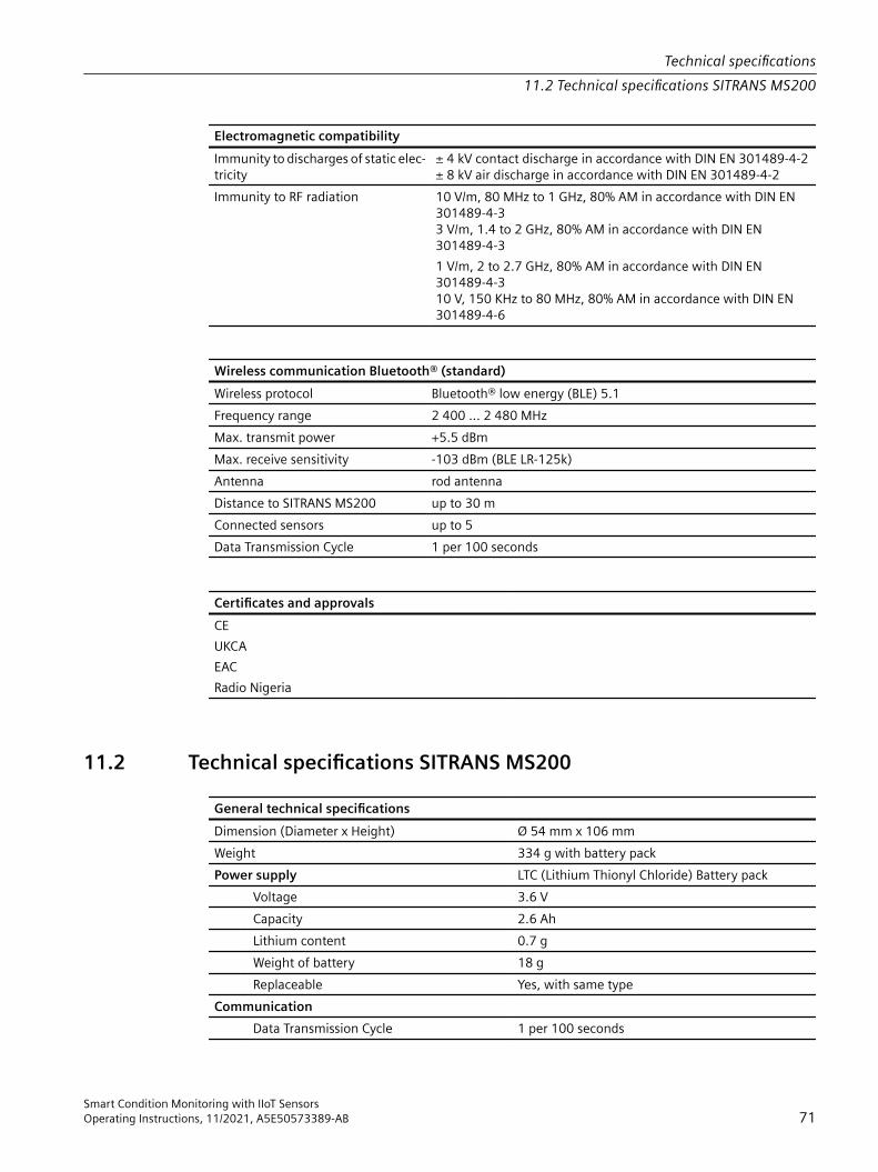
Electromagnetic compatibilityImmunity to discharges of static elec‐tricity
± 4 kV contact discharge in accordance with DIN EN 301489-4-2± 8 kV air discharge in accordance with DIN EN 301489-4-2
Immunity to RF radiation 10 V/m, 80 MHz to 1 GHz, 80% AM in accordance with DIN EN 301489-4-33 V/m, 1.4 to 2 GHz, 80% AM in accordance with DIN EN 301489-4-31 V/m, 2 to 2.7 GHz, 80% AM in accordance with DIN EN 301489-4-310 V, 150 KHz to 80 MHz, 80% AM in accordance with DIN EN 301489-4-6
Wireless communication Bluetooth® (standard)Wireless protocol Bluetooth® low energy (BLE) 5.1Frequency range 2 400 ... 2 480 MHzMax. transmit power +5.5 dBmMax. receive sensitivity -103 dBm (BLE LR-125k)Antenna rod antennaDistance to SITRANS MS200 up to 30 mConnected sensors up to 5Data Transmission Cycle 1 per 100 seconds
Certificates and approvals CEUKCAEACRadio Nigeria
11.2 Technical specifications SITRANS MS200General technical specifications Dimension (Diameter x Height) Ø 54 mm x 106 mmWeight 334 g with battery packPower supply LTC (Lithium Thionyl Chloride) Battery pack Voltage 3.6 V Capacity 2.6 Ah Lithium content 0.7 g Weight of battery 18 g Replaceable Yes, with same typeCommunication Data Transmission Cycle 1 per 100 seconds
Technical specifications11.2 Technical specifications SITRANS MS200
Smart Condition Monitoring with IIoT SensorsOperating Instructions, 11/2021, A5E50573389-AB 71

General technical specifications Battery life at @ 25 °C up to 3.5 years, depending on signal strengthEnvironment Storage temperature -40 ... 85 °C Ambient temperature (operation) -30 ... 80 °C Altitude Operation: -1000 ... 2000 m (pressure
795 ... 1080 hPa)Rating IP68 (2 m, 24 h)
Temperature measurement Temperature range -30 ... +80 °CResolution 0.01 °CRepeatability ±0.15 °CAccuracy ±4 °CData format 16 bits
Vibration measurement Vibration sensor 3-axis accelerometerFrequency range 13 ... 3 300 HzMeasurement range ±16 gResolution 0.488 mgRepeatability ±10 mgAccuracy ±10% of measurement rangeSampling rate 6 600 HzData format 16 bits
Wireless communication Bluetooth® (standard) Wireless protocol Bluetooth® low energy (BLE) 5.1Frequency range 2 400 ... 2 480 MHzMax. transmit power +4 dBm max.Receive sensitivity -88 dBmAntenna integratedDistance to SITRANS CC220 up to 30 m
Certificates and approvals CEUKCAEACRadio Nigeria
Technical specifications11.2 Technical specifications SITRANS MS200
Smart Condition Monitoring with IIoT Sensors72 Operating Instructions, 11/2021, A5E50573389-AB
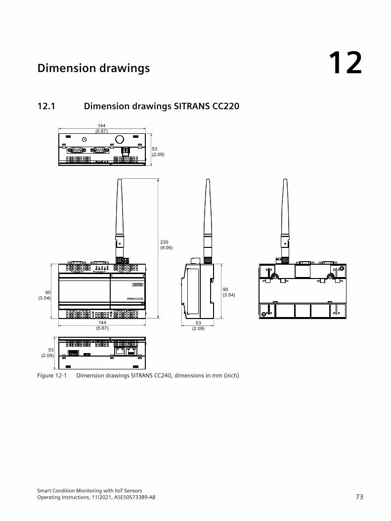
Dimension drawings 1212.1 Dimension drawings SITRANS CC220
53
(2.09)
90
(3.54)
90
(3.54)
230
(9.06)
53
(2.09)
144
(5.67)
144
(5.67)53
(2.09)
Figure 12-1 Dimension drawings SITRANS CC240, dimensions in mm (inch)
Smart Condition Monitoring with IIoT SensorsOperating Instructions, 11/2021, A5E50573389-AB 73

12.2 Dimension drawings SITRANS MS200
M8
SW 19
13
(0.5
1)
10
(0
.39)
82
(3.2
3)
10
5
(4.1
7)
Ø46
(1.81)
Figure 12-2 mm (inch)
Dimension drawings12.2 Dimension drawings SITRANS MS200
Smart Condition Monitoring with IIoT Sensors74 Operating Instructions, 11/2021, A5E50573389-AB

Product documentation and support AA.1 Product documentation
Process instrumentation product documentation is available in the following formats: • Certificates (http://www.siemens.com/processinstrumentation/certificates) • Downloads (firmware, EDDs, software) (http://www.siemens.com/processinstrumentation/
downloads) • Catalog and catalog sheets (http://www.siemens.com/processinstrumentation/catalogs) • Manuals (http://www.siemens.com/processinstrumentation/documentation)
You have the option to show, open, save, or configure the manual.– "Display": Open the manual in HTML5 format– "Configure": Register and configure the documentation specific to your plant– "Download": Open or save the manual in PDF format– "Download as html5, only PC": Open or save the manual in the HTML5 view on your PC
You can also find manuals with the Mobile app at Industry Online Support (https://support.industry.siemens.com/cs/ww/en/sc/2067). Download the app to your mobile device and scan the device QR code.
Product documentation by serial numberUsing the PIA Life Cycle Portal, you can access the serial number-specific product information including technical specifications, spare parts, calibration data, or factory certificates.
Entering a serial number1. Open the PIA Life Cycle Portal (https://www.pia-portal.automation.siemens.com).2. Select the desired language.3. Enter the serial number of your device. The product documentation relevant for your device
is displayed and can be downloaded.To display factory certificates, if available, log in to the PIA Life Cycle Portal using your login or register.
Scanning a QR code1. Scan the QR code on your device with a mobile device.2. Click "PIA Portal".To display factory certificates, if available, log in to the PIA Life Cycle Portal using your login or register.
Smart Condition Monitoring with IIoT SensorsOperating Instructions, 11/2021, A5E50573389-AB 75

A.2 Technical support
Technical supportIf this documentation does not completely answer your technical questions, you can enter a Support Request (http://www.siemens.com/automation/support-request). For help creating a support request, view this video here (www.siemens.com/opensr). Additional information on our technical support can be found at Technical Support (http://www.siemens.com/automation/csi/service).
Service & support on the Internet In addition to our technical support, Siemens offers comprehensive online services at Service & Support (http://www.siemens.com/automation/serviceandsupport).
Contact If you have further questions about the device, contact your local Siemens representative at Personal Contact (http://www.automation.siemens.com/partner).To find the contact for your product, go to "all products and branches" and select "Products & Services > Industrial automation > Process instrumentation".Contact address for business unit: Siemens AGDigital IndustriesProcess AutomationÖstliche Rheinbrückenstr. 50 76187 Karlsruhe, Germany
See alsoSending the log files to technical support (Page 54)
Product documentation and supportA.2 Technical support
Smart Condition Monitoring with IIoT Sensors76 Operating Instructions, 11/2021, A5E50573389-AB

Ordering data BB.1 Accessories
You can order accessories online: Industry Mall (https://mall.industry.siemens.com/mall/en/WW/Catalog/Products/10048376?tree=CatalogTree)
Smart Condition Monitoring with IIoT SensorsOperating Instructions, 11/2021, A5E50573389-AB 77

Ordering dataB.1 Accessories
Smart Condition Monitoring with IIoT Sensors78 Operating Instructions, 11/2021, A5E50573389-AB
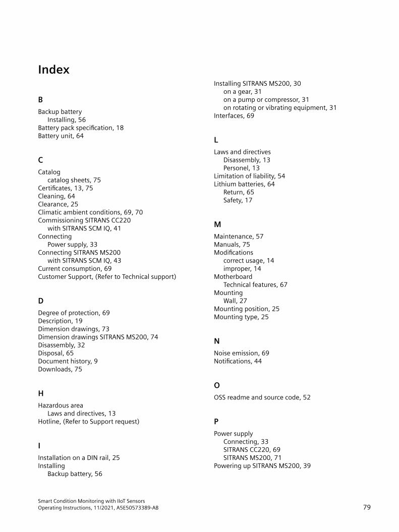
Index
BBackup battery
Installing, 56Battery pack specification, 18Battery unit, 64
CCatalog
catalog sheets, 75Certificates, 13, 75Cleaning, 64Clearance, 25Climatic ambient conditions, 69, 70Commissioning SITRANS CC220
with SITRANS SCM IQ, 41Connecting
Power supply, 33Connecting SITRANS MS200
with SITRANS SCM IQ, 43Current consumption, 69Customer Support, (Refer to Technical support)
DDegree of protection, 69Description, 19Dimension drawings, 73Dimension drawings SITRANS MS200, 74Disassembly, 32Disposal, 65Document history, 9Downloads, 75
HHazardous area
Laws and directives, 13Hotline, (Refer to Support request)
IInstallation on a DIN rail, 25Installing
Backup battery, 56
Installing SITRANS MS200, 30on a gear, 31on a pump or compressor, 31on rotating or vibrating equipment, 31
Interfaces, 69
LLaws and directives
Disassembly, 13Personel, 13
Limitation of liability, 54Lithium batteries, 64
Return, 65Safety, 17
MMaintenance, 57Manuals, 75Modifications
correct usage, 14improper, 14
MotherboardTechnical features, 67
MountingWall, 27
Mounting position, 25Mounting type, 25
NNoise emission, 69Notifications, 44
OOSS readme and source code, 52
PPower supply
Connecting, 33SITRANS CC220, 69SITRANS MS200, 71
Powering up SITRANS MS200, 39
Smart Condition Monitoring with IIoT SensorsOperating Instructions, 11/2021, A5E50573389-AB 79

RRadiation, 15
High frequency radiation, 15Repairs, 54Replacing battery pack, 59Return procedure, 65
SScope of delivery, 10Service, 76Service and support
Internet, 76Support, 76Support request, 76
TTechnical specifications
SITRANS MS200, 71, 72Technical support, 76
partner, 76personal contact, 76
Test certificates, 13
UUSB stick, 69
WWall mounting, 25, 27Warranty, 11Weight
SITRANS CC220, 69SITRANS MS200, 71
Index
Smart Condition Monitoring with IIoT Sensors80 Operating Instructions, 11/2021, A5E50573389-AB