significantly improved lifetime of micro-channel plate pmts
TRANSCRIPT
Nuclear Instruments and Methods in Physics Research A 718 (2013) 535–540
Contents lists available at SciVerse ScienceDirect
Nuclear Instruments and Methods inPhysics Research A
0168-90
http://d
n Corr
E-m
lehman
journal homepage: www.elsevier.com/locate/nima
Significantly improved lifetime of micro-channel plate PMTs
A. Lehmann a,n, A. Britting a, W. Eyrich a, C. Schwarz b, J. Schwiening b, F. Uhlig a
a Physikalisches Institut IV, Universitat Erlangen-Nurnberg, Erwin-Rommel-Straße 1, D-91058 Erlangen, Germanyb GSI Helmholtzzentrum fur Schwerionenforschung GmbH, Planckstraße 1, D-64291 Darmstadt, Germany
a r t i c l e i n f o
Available online 29 November 2012
Keywords:
PANDA experiment
DIRC
Photo detectors
MCP-PMT
Lifetime
02/$ - see front matter & 2012 Elsevier B.V. A
x.doi.org/10.1016/j.nima.2012.11.109
esponding author.
ail addresses: [email protected]
[email protected] (A. Lehmann).
a b s t r a c t
The lifetime of the most recent generation micro-channel plate (MCP) PMTs of BINP, Hamamatsu
(R10754X) and PHOTONIS (XP85112) is being studied in a simultaneous measurement. We find that the
new techniques applied to reduce the aging of the photocathode of the MCP-PMTs has significantly
increased the lifetime. Dark count rate, gain and quantum efficiency of the tubes are given as a function
of the integrated anode charge. Several times the quantum efficiency was also measured across the
surface of the photocathode. At this point of the ongoing measurements the best MCP-PMT turns out to
be the XP85112 with its MCP surfaces coated by an atomic layer to reduce the outgassing of the lead
glass. This tube shows no aging after an integrated anode charge of 2.1 C/cm2 which is more than an
order of magnitude better than that of previous generation MCP-PMTs.
& 2012 Elsevier B.V. All rights reserved.
1. Introduction
Micro-channel plate (MCP) photomultipliers (PMT) are thepreferred sensors for the particle identification system of thePANDA detector at the new FAIR facility at GSI in Darmstadt.The PANDA experiment [1,2] will investigate antiproton–protonannihilations at luminosities up to 2�1032 cm�2 s�1 and at p
momenta up to 15 GeV/c, with the main emphasis on charmo-nium spectroscopy and the search for exotic states. Many of thesestates decay into charged pions and kaons with typical momentaof a few GeV/c. DIRC (Detection of Internally Reflected Cherenkovlight) detectors [3] were chosen as the main particle identificationsystem. Since for various reasons the PANDA detector has to bevery compact.
The focal planes of the DIRC detectors, a ‘‘Barrel DIRC’’surrounding the target and an ‘‘Endcap Disc DIRC’’ covering theforward hemisphere [4–6], will be placed inside the magneticfield of the PANDA solenoid of up to 2 Tesla. This and otherrequirements put serious constraints to the photon sensors: agood geometrical resolution, the detection of only few singlephotons per track inside a high magnetic field, a very good timeresolution of o100 ps, a low dark count rate, a high detectionefficiency, and a rate capability of up to several MHz/cm2. Whilethese demands are met by most of the MCP-PMTs of the latestgeneration, their aging properties still remain an issue.
ll rights reserved.
angen.de,
At the highest luminosities, assuming 100% duty cycle ofPANDA and a gain of 106, the integrated anode charge of anMCP-PMT at the Barrel DIRC will be � 1 C=cm2=year, and even5 times higher for the Endcap Disc DIRC. Until recently thecommercial MCP-PMTs typically were unusable after an anodecharge of o200 mC=cm2 [7,8]. The main aging effect inside anMCP-PMT concerns the quantum efficiency (QE) of the photo-cathode (PC). Some of the residual gas atoms inside the tube areionized by the electron avalanche, and these ions are acceleratedtowards the PC which gets damaged by this permanent bombard-ment. As a consequence the QE decreases until it is not sufficientanymore for useful measurements.
2. Approaches to increase the lifetime
To increase the lifetime of MCP-PMTs the manufacturersrecently started applying various countermeasures to avoid adamaging of the PC due to ion back drift. Currently the three mainmanufacturers of MCP-PMTs, Budker Institute of Nuclear Physics(BINP) in Novosibirsk, Hamamatsu and PHOTONIS, apply differenttechniques to reduce the effects of aging.
The first attempt was a thin (5–10 nm) layer of aluminumoxide in front of the first MCP stage. This protection filmtechnique was applied to some of the MCP-PMTs of BINP andalso of Hamamatsu. However, the disadvantage of this techniqueis a � 40% reduction of the collection efficiency. To avoid this lossHamamatsu recently puts the protection layer between the twoMCP stages [9] and BINP does not use a film anymore.
Another approach pursued first by PHOTONIS and now alsoby BINP is a better vacuum inside the tube and to clean the MCP
A. Lehmann et al. / Nuclear Instruments and Methods in Physics Research A 718 (2013) 535–540536
surfaces by electron scrubbing. This resulted in an improvedlifetime of the MCP-PMTs. The latest step applied by PHOTONISis coating the MCP capillaries with an atomic layer deposition(ALD) technique. This allows an optimization of the resistanceand the secondary electron emission capability using different
0 500 1000 1500
dark
coun
t rat
e [k
Hz]
0
100
200
300
400
500
600BINP 1359BINP 3548
BINP 1359 + 3548
0 500 1000 1500
dark
coun
t rat
e [k
Hz/
pixe
l]
10-3
10-1
10-2
1Pixel 6Pixel 10Pixel 11Pixel 15
Hamamatsu R10754X-M16
0 500 1000 1500 2000
dark
coun
t rat
e [k
Hz/
pixe
l]
0
0.05
0.1
0.15
0.2
0.25Pixel 22Pixel 33Pixel 32Pixel 57
PHOTONIS XP85112/A1-HGL
integrated anode charge [mC/cm2]
integrated anode charge [mC/cm2]
integrated anode charge [mC/cm2]
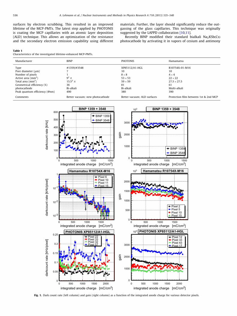
Fig. 1. Dark count rate (left column) and gain (right column) as a fun
Table 1Characteristics of the investigated lifetime-enhanced MCP-PMTs.
Manufacturer BINP
Type #1359/#3548
Pore diameter (mm) 7
Number of pixels 1
Active area (mm2) 92 pTotal area (mm2) 15.52 pGeometrical efficiency (%) 36
photocathode Bi-alkali
Peak quantum efficiency (@nm) 490
Comments Better vacuum; new photocathode
materials. Further, the layer should significantly reduce the out-gassing of the glass capillaries. This technique was originallysuggested by the LAPPD collaboration [10,11].
Recently BINP modified their standard bialkali Na2KSbðCsÞphotocathode by activating it in vapors of cesium and antimony
0 500 1000 1500
gain
0
1000
2000
3000
×103
×103
×103
BINP 1359BINP 3548
BINP 1359 + 3548
integrated anode charge [mC/cm2]
integrated anode charge [mC/cm2]
integrated anode charge [mC/cm2]
0 500 1000 1500
gain
0
500
1000
1500
2000
Pixel 2Pixel 5Pixel 10Pixel 15
Hamamatsu R10754X-M16
0 500 1000 1500 2000
gain
0
1000
2000
3000
Pixel 12Pixel 33Pixel 43Pixel 17
PHOTONIS XP85112/A1-HGL
ction of the integrated anode charge for various detector pixels.
PHOTONIS Hamamatsu
XP85112/A1-HGL R10754X-01-M16
10 10
8�8 4�4
53�53 22�22
59�59 27.5�27.5
81 61
Bi-alkali Multi-alkali
380 390
Better vacuum; ALD surfaces Protection film between 1st & 2nd MCP
A. Lehmann et al. / Nuclear Instruments and Methods in Physics Research A 718 (2013) 535–540 537
which leads to an adsorption of extra Cs and Sb at the surface [12].This modified PC has a higher sensitivity in the near infrared regionand a significantly higher dark count rate of 4100 kHz=cm2, but alsoa considerably reduced sensitivity to damage by ion back flowresulting in a longer lifetime of the MCP-PMT.
3. Setup
Lifetime measurements of MCP-PMTs are complicated andtime-consuming. This is the main reason why until recently therewere only very few studies available dealing with the aging ofMCP-PMTs [7,13]. Moreover, the few data were taken in quitedifferent environments (pulse rate and light intensity) making itdifficult to directly compare the results. To overcome this limita-tion our group has started simultaneous aging measurementswith the currently available lifetime-enhanced MCP-PMTs:multi-anode devices from Hamamatsu (R10754X) and PHOTONIS(XP85112/A1-HGL), and two single-anode sensors from BINP (seeTable 1).
During the aging the MCP-PMTs were continuously illumi-nated with a 460 nm LED whose intensity was reduced to singlephoton level with neutral density filters. With a lens the lightspot of the LED was broadened to a size that covered the PCs of allMCP-PMTs and illuminated them with a nearly homogeneousintensity across the whole surface. The rate chosen was 270 kHzat the beginning which corresponds roughly to the expectedsingle photon rate at the image plane of the Barrel DIRC. Later
x [mm]-20 -10
y [m
m]
-20
-10
6
8
10186 mC/cm2
x [mm]-20 -10
y [m
m]
-20
-10
5
10
15
20
25100 mC/cm2
x [mm]-50 -40 -30 -20 -10 0
y [m
m]
-50
-40
-30
-20
-10
0
5
10
15
20
25125 mC/cm2
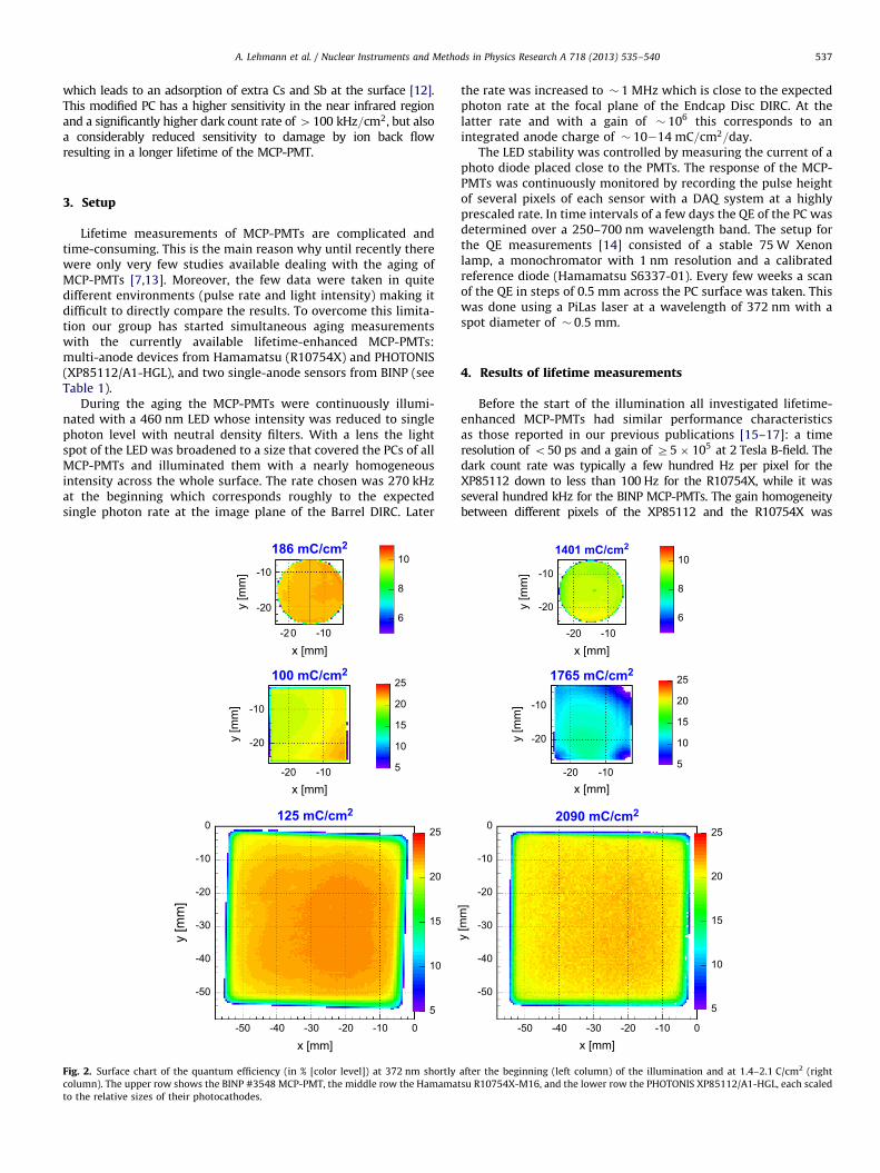
Fig. 2. Surface chart of the quantum efficiency (in % [color level]) at 372 nm shortly
column). The upper row shows the BINP #3548 MCP-PMT, the middle row the Hamama
to the relative sizes of their photocathodes.
the rate was increased to � 1 MHz which is close to the expectedphoton rate at the focal plane of the Endcap Disc DIRC. At thelatter rate and with a gain of � 106 this corresponds to anintegrated anode charge of � 10214 mC=cm2=day.
The LED stability was controlled by measuring the current of aphoto diode placed close to the PMTs. The response of the MCP-PMTs was continuously monitored by recording the pulse heightof several pixels of each sensor with a DAQ system at a highlyprescaled rate. In time intervals of a few days the QE of the PC wasdetermined over a 250–700 nm wavelength band. The setup forthe QE measurements [14] consisted of a stable 75 W Xenonlamp, a monochromator with 1 nm resolution and a calibratedreference diode (Hamamatsu S6337-01). Every few weeks a scanof the QE in steps of 0.5 mm across the PC surface was taken. Thiswas done using a PiLas laser at a wavelength of 372 nm with aspot diameter of � 0:5 mm.
4. Results of lifetime measurements
Before the start of the illumination all investigated lifetime-enhanced MCP-PMTs had similar performance characteristicsas those reported in our previous publications [15–17]: a timeresolution of o50 ps and a gain of Z5� 105 at 2 Tesla B-field. Thedark count rate was typically a few hundred Hz per pixel for theXP85112 down to less than 100 Hz for the R10754X, while it wasseveral hundred kHz for the BINP MCP-PMTs. The gain homogeneitybetween different pixels of the XP85112 and the R10754X was
x [mm]
y [m
m]
-20
-10
6
8
101401 mC/cm2
x [mm]
-20 -10
-20 -10
y [m
m]
-20
-10
5
10
15
20
251765 mC/cm2
x [mm]-50 -40 -30 -20 -10 0
y [m
m]
-50
-40
-30
-20
-10
0
5
10
15
20
252090 mC/cm2
after the beginning (left column) of the illumination and at 1.4–2.1 C/cm2 (right
tsu R10754X-M16, and the lower row the PHOTONIS XP85112/A1-HGL, each scaled
A. Lehmann et al. / Nuclear Instruments and Methods in Physics Research A 718 (2013) 535–540538
moderate with room for improvements, the crosstalk among adjacentpixels was tolerable. All MCP-PMTs showed sufficient rate capabilityfor the Barrel DIRC, while only the Hamamatsu R10754X can digest42 MHz=cm2 which would be enough for the Endcap Disc DIRC.
4.1. Dark count
The behavior of the dark count rate during the illuminationprocess is shown in the left column of Fig. 1. For the BINP (upper)and the XP85112 (lower row) MCP-PMTs the dark count ratedecreases somewhat at the very beginning of the illuminationwhile it stays roughly constant thereafter. This trend is in contrastto the previous generation MCP-PMTs which usually showed acontinuously decreasing slope during the accumulation of theanode charge. The rate of the Hamamatsu R10754X (middle row)
integrated anode charge [mC/cm2]0 500 1000 1500
QE
[%]
3
10
20300 nm350 nm375 nm400 nm425 nm450 nm500 nm550 nm600 nm
BINP 3548
integrated anode charge [mC/cm2]0 500 1000 1500
QE
[%]
3
10
20300 nm350 nm375 nm400 nm425 nm450 nm500 nm550 nm600 nm
Hamamatsu R10754X-M16
integrated anode charge [mC/cm2]0 500 1000 1500 2000
QE
[%]
3
10
20300 nm350 nm375 nm400 nm425 nm450 nm500 nm550 nm600 nm
PHOTONIS XP85112/A1-HGL
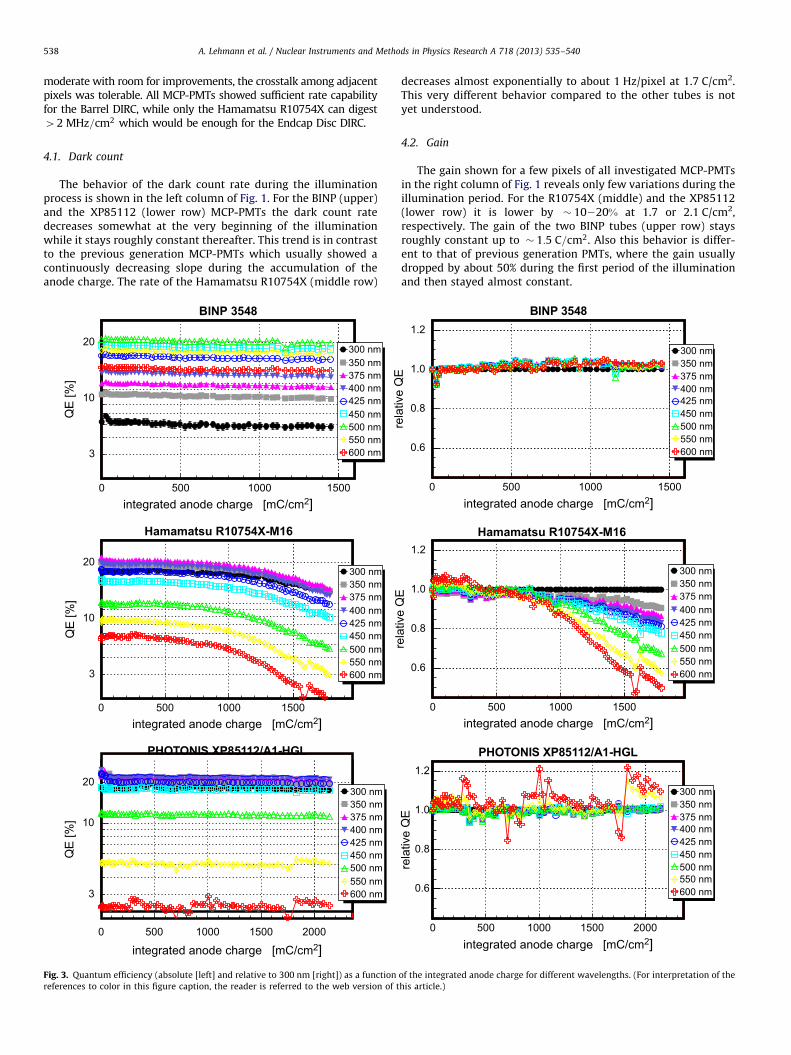
Fig. 3. Quantum efficiency (absolute [left] and relative to 300 nm [right]) as a function
references to color in this figure caption, the reader is referred to the web version of t
decreases almost exponentially to about 1 Hz/pixel at 1.7 C/cm2.This very different behavior compared to the other tubes is notyet understood.
4.2. Gain
The gain shown for a few pixels of all investigated MCP-PMTsin the right column of Fig. 1 reveals only few variations during theillumination period. For the R10754X (middle) and the XP85112(lower row) it is lower by � 10220% at 1.7 or 2.1 C/cm2,respectively. The gain of the two BINP tubes (upper row) staysroughly constant up to � 1:5 C=cm2. Also this behavior is differ-ent to that of previous generation PMTs, where the gain usuallydropped by about 50% during the first period of the illuminationand then stayed almost constant.
integrated anode charge [mC/cm2]0 500 1000 1500
rela
tive
QE
0.6
0.8
1.0
1.2
300 nm350 nm375 nm400 nm425 nm450 nm500 nm550 nm600 nm
BINP 3548
integrated anode charge [mC/cm2]0 500 1000 1500
rela
tive
QE
0.6
0.8
1.0
1.2
300 nm350 nm375 nm400 nm425 nm450 nm500 nm550 nm600 nm
Hamamatsu R10754X-M16
integrated anode charge [mC/cm2]0 500 1000 1500 2000
rela
tive
QE
0.6
0.8
1.0
1.2
300 nm350 nm375 nm400 nm425 nm450 nm500 nm550 nm600 nm
PHOTONIS XP85112/A1-HGL
of the integrated anode charge for different wavelengths. (For interpretation of the
his article.)
0 500 1000 1500 2000
QE
[%]
0
5
10
15
20
25QE (400 nm) vs. Charge
Phot. XP85112/A1-HGL-9001223 (10µm)Phot. XP85112/A1-HGL-9001223 covered(10µm)Ham. R10754-01-M16 (JT0117 - 10µm)BINP 1359 (7µm)BINP 3548 (7µm)Phot. XP85112/A1-9000897 (10µm)Phot. XP85012-9000296 (25µm)BINP 82 (6µm)
integrated anode charge[mC/cm2]
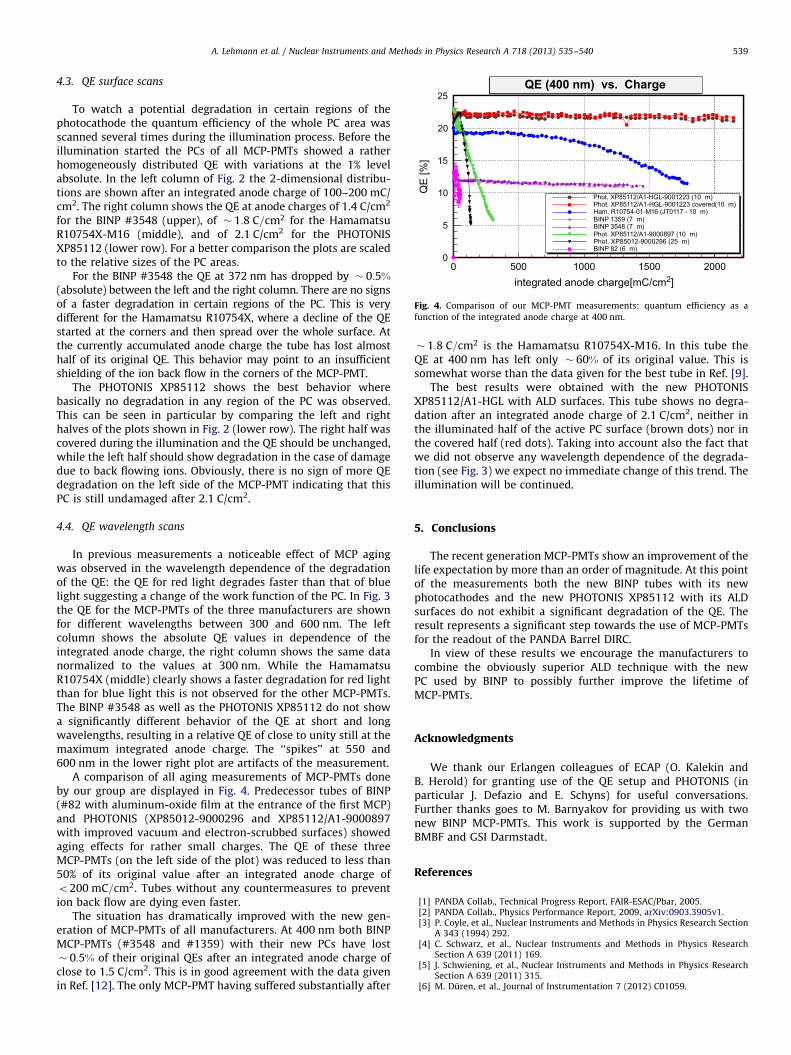
Fig. 4. Comparison of our MCP-PMT measurements: quantum efficiency as a
function of the integrated anode charge at 400 nm.
A. Lehmann et al. / Nuclear Instruments and Methods in Physics Research A 718 (2013) 535–540 539
4.3. QE surface scans
To watch a potential degradation in certain regions of thephotocathode the quantum efficiency of the whole PC area wasscanned several times during the illumination process. Before theillumination started the PCs of all MCP-PMTs showed a ratherhomogeneously distributed QE with variations at the 1% levelabsolute. In the left column of Fig. 2 the 2-dimensional distribu-tions are shown after an integrated anode charge of 100–200 mC/cm2. The right column shows the QE at anode charges of 1.4 C/cm2
for the BINP #3548 (upper), of � 1:8 C=cm2 for the HamamatsuR10754X-M16 (middle), and of 2.1 C/cm2 for the PHOTONISXP85112 (lower row). For a better comparison the plots are scaledto the relative sizes of the PC areas.
For the BINP #3548 the QE at 372 nm has dropped by � 0:5%(absolute) between the left and the right column. There are no signsof a faster degradation in certain regions of the PC. This is verydifferent for the Hamamatsu R10754X, where a decline of the QEstarted at the corners and then spread over the whole surface. Atthe currently accumulated anode charge the tube has lost almosthalf of its original QE. This behavior may point to an insufficientshielding of the ion back flow in the corners of the MCP-PMT.
The PHOTONIS XP85112 shows the best behavior wherebasically no degradation in any region of the PC was observed.This can be seen in particular by comparing the left and righthalves of the plots shown in Fig. 2 (lower row). The right half wascovered during the illumination and the QE should be unchanged,while the left half should show degradation in the case of damagedue to back flowing ions. Obviously, there is no sign of more QEdegradation on the left side of the MCP-PMT indicating that thisPC is still undamaged after 2.1 C/cm2.
4.4. QE wavelength scans
In previous measurements a noticeable effect of MCP agingwas observed in the wavelength dependence of the degradationof the QE: the QE for red light degrades faster than that of bluelight suggesting a change of the work function of the PC. In Fig. 3the QE for the MCP-PMTs of the three manufacturers are shownfor different wavelengths between 300 and 600 nm. The leftcolumn shows the absolute QE values in dependence of theintegrated anode charge, the right column shows the same datanormalized to the values at 300 nm. While the HamamatsuR10754X (middle) clearly shows a faster degradation for red lightthan for blue light this is not observed for the other MCP-PMTs.The BINP #3548 as well as the PHOTONIS XP85112 do not showa significantly different behavior of the QE at short and longwavelengths, resulting in a relative QE of close to unity still at themaximum integrated anode charge. The ‘‘spikes’’ at 550 and600 nm in the lower right plot are artifacts of the measurement.
A comparison of all aging measurements of MCP-PMTs doneby our group are displayed in Fig. 4. Predecessor tubes of BINP(#82 with aluminum-oxide film at the entrance of the first MCP)and PHOTONIS (XP85012-9000296 and XP85112/A1-9000897with improved vacuum and electron-scrubbed surfaces) showedaging effects for rather small charges. The QE of these threeMCP-PMTs (on the left side of the plot) was reduced to less than50% of its original value after an integrated anode charge ofo200 mC=cm2. Tubes without any countermeasures to prevention back flow are dying even faster.
The situation has dramatically improved with the new gen-eration of MCP-PMTs of all manufacturers. At 400 nm both BINPMCP-PMTs (#3548 and #1359) with their new PCs have lost� 0:5% of their original QEs after an integrated anode charge ofclose to 1.5 C/cm2. This is in good agreement with the data givenin Ref. [12]. The only MCP-PMT having suffered substantially after
� 1:8 C=cm2 is the Hamamatsu R10754X-M16. In this tube theQE at 400 nm has left only � 60% of its original value. This issomewhat worse than the data given for the best tube in Ref. [9].
The best results were obtained with the new PHOTONISXP85112/A1-HGL with ALD surfaces. This tube shows no degra-dation after an integrated anode charge of 2.1 C/cm2, neither inthe illuminated half of the active PC surface (brown dots) nor inthe covered half (red dots). Taking into account also the fact thatwe did not observe any wavelength dependence of the degrada-tion (see Fig. 3) we expect no immediate change of this trend. Theillumination will be continued.
5. Conclusions
The recent generation MCP-PMTs show an improvement of thelife expectation by more than an order of magnitude. At this pointof the measurements both the new BINP tubes with its newphotocathodes and the new PHOTONIS XP85112 with its ALDsurfaces do not exhibit a significant degradation of the QE. Theresult represents a significant step towards the use of MCP-PMTsfor the readout of the PANDA Barrel DIRC.
In view of these results we encourage the manufacturers tocombine the obviously superior ALD technique with the newPC used by BINP to possibly further improve the lifetime ofMCP-PMTs.
Acknowledgments
We thank our Erlangen colleagues of ECAP (O. Kalekin andB. Herold) for granting use of the QE setup and PHOTONIS (inparticular J. Defazio and E. Schyns) for useful conversations.Further thanks goes to M. Barnyakov for providing us with twonew BINP MCP-PMTs. This work is supported by the GermanBMBF and GSI Darmstadt.
References
[1] PANDA Collab., Technical Progress Report, FAIR-ESAC/Pbar, 2005.[2] PANDA Collab., Physics Performance Report, 2009, arXiv:0903.3905v1.[3] P. Coyle, et al., Nuclear Instruments and Methods in Physics Research Section
A 343 (1994) 292.[4] C. Schwarz, et al., Nuclear Instruments and Methods in Physics Research
Section A 639 (2011) 169.[5] J. Schwiening, et al., Nuclear Instruments and Methods in Physics Research
Section A 639 (2011) 315.[6] M. Duren, et al., Journal of Instrumentation 7 (2012) C01059.

A. Lehmann et al. / Nuclear Instruments and Methods in Physics Research A 718 (2013) 535–540540
[7] N. Kishimoto, et al., Nuclear Instruments and Methods in Physics ResearchSection A 564 (2006) 204.
[8] A. Britting, et al., Journal of Instrumentation 6 (2011) C10001.[9] T. Jinno, et al., Nuclear Instruments and Methods in Physics Research Section
A 629 (2011) 111.[10] M. Wettstein, et al., Nuclear Instruments and Methods in Physics Research
Section A 639 (2011) 148.[11] O.H.W. Siegmund, et al., Nuclear Instruments and Methods in Physics
Research Section A 639 (2011) 165.[12] M.Yu. Barnyakov, A.V. Mironov, Journal of Instrumentation JINST 6 (2011)
C12026.
[13] A.Yu. Barnyakov, et al., Nuclear Instruments and Methods in Physics ResearchSection A 567 (2006) 17.
[14] O. Kalekin, et al., Nuclear Instruments and Methods in Physics Research
Section A 626–627 (2011) 151.[15] A. Lehmann, et al., Nuclear Instruments and Methods in Physics Research
Section A 595 (2008) 173.[16] A. Lehmann, et al., Journal of Instrumentation 4 (2009) P11024.[17] A. Lehmann, et al., Nuclear Instruments and Methods in Physics Research
Section A 639 (2011) 144.