#~+ustrated pmts list for
TRANSCRIPT
T&687 Jan 18/79
Revised Peb. 15/83
OPERATION AND MAINTENANCE MANUAL
with
#~+uSTRATED PmTs LIST
FOR
28.5 VOLT DC STATIC, REGULATED POWER SUPPLY
(With Adjustable Current Limiting Feature)
covering
Specification No. 5918A-1 (50 H7;)
Model No. 5FR28-400CL
Specification No. 5918A-2 (60 Hz)
Model No. 6FR28-400CL
Specification No. 5918A-3 (60 Hz)
575 Volts Input
Model No. 6FR28-400CL
HOBART BROTHERS COXPANY POWER SYSTEMS DIVISION
TROY, OHIO 45373 U.S.A.

,,--

ELECTRIC SHOCK can kill. Do not touch live electrical parts.
ELECTRIC ARC FLASH can injure eyes burn skin ignite combustible materia i.
cause equipment damage and Do not use power cables to
break load and prevent tools from causing short circuits. I ! IMPROPER PHASE CONNECTION, PARALLELING, OR USE can damage this and attached:
equipment.
IMPORTANT: - Protect all operating personnel. Read, understand, and follow ' all instructions in the Oueratina/Instruction Manual before
A.
installing, operating, or-serviczng the equipment. available for future use by all operators.
Keep the manual
GENERAL
Equipment that supplies electrical power can cause serious injury or death, or damage to other equipment or property. The operator must strictly ! observe all safety rules and take precautionary actions. Safe practices have been developed from past experience in the use of power source equipment. While certain practices below apply only to electrically-powered equipment, other practices apply to engine-driven equipment, and some practices to'both.
SHOCK PREVENTION
Bare conductors, or terminals in the output circuit, or ungrounded, electrically-live equipment can fatally shock a person. Have a certified electrician verify that the equipment is adequately grounded and learn what terminals and parts are electrically HOT. Avoid hot spots on machine. Use proper safety clothing, procedures, and test equipment.
The electrical resistance of the body is decreased when wet, permitting dangerous currents to flow through it. equipment, do not work in damp areas.
When inspecting or servicing
dry wood, Stand on a dry rubber mat or
use insulating gloves when dampness or sweat cannot be avoided. Keep clothing dry, and never work alone,
1. Installation and Grounding of Electrically Powered Equipment ,
Equipment driven by electric motors (rather than by diesel or gasoline engines) must be installed and maintained in accordance with the National Electrical Code, ANSI/'NFPA 70, and other applicable codes'. A power disconnect switch or circuit breaker must be located at the equipment. Check the nameplate for volta e, frequency, and phase requirements. If only 3-phase power is availab e, f connect any single-phase rated equipment to only two wires of the 3-phase line. DO NOT CONNECT the equipment grounding conductor (lead) to the third live wire of the 3-phase line, as this makes the equipment frame electrically HOT, which can cause a fatal ?rEimc.-- -----
Alwa s connect the grounding lead to
if supplied in a power line cable, t x e grounded switch box or building ground.
separate groundin If not provided, use a
of the grounding !T lead. Ensure that the current ead will
(am erage) r!
capacity ault current
situation. be adequate for the worst
details. Refer to the National Electrical Code ANSI/NFPA 70 for
Do not remove plug ground prongs. Use correctly mating receptacles.
2. Output Cables and Terminals
Inspect cables frequently for damage to the insulation and the connectors. Re lace or repair cracked or worn cables immediately. 'Do not overload ca les. 1 Do not touch output terminal while equipment {s
i
energized. i
I
3. Service and Maintenance
4 fi ." ../. _ -. ".-- --Thise_ uivm condit 4;
ent mua be maintained ia.good electrical and me-cha.n.i.n&li ' j on to avoid hazards stemming from disrepx Report any 1-y
equipment defect or safet hazard to the supervisor and discontinue
*'
: 3-. -I- - ..--.-- ..-_._ u-se-.af-..t.&..-e
should be mag?men t--unt~ .-its-sa-fety-hns~-been
I.. .." ,...... y qualified personnel only.
assured-;-.---Repairs- --.---'...- -.-- i
I_ __- I"-"._i . ..^ I .__ Instruction 910082 Feb 25/86 Revised
Page 1
. / ‘. /’ 1 , , -. 2 /Y i
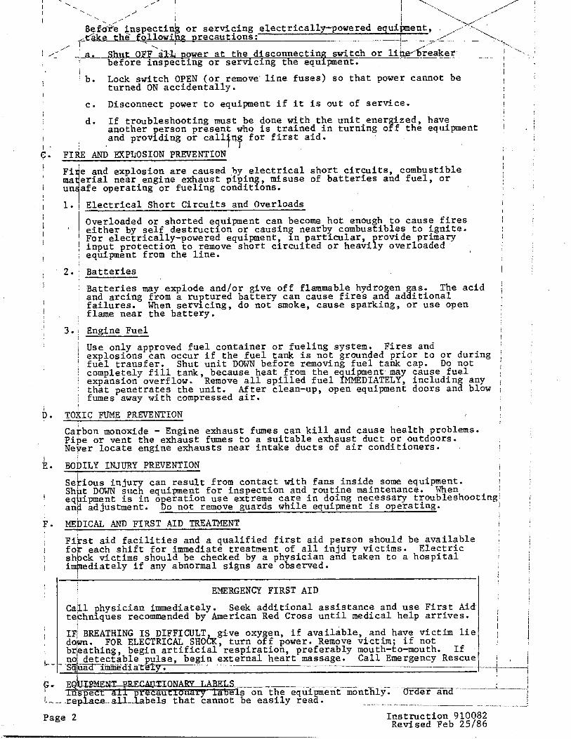
. ,“--- I Be&& inspectin or servicing electrically-powered equiLent, //+,*N,~
--.~,--
+&&e the' followi recautions: -___. _ 1 -----& - ,+Y' .-
.j_a,Shu.&-QFF'al& power at the disconnecting switch or lideaker
---LSh, I . “N..
-,-" _--.-_ -- . ..- i
I -_ before inspecting or servicing the equipment. I
b. Lock switch OPEN (or remove-line fuses) so that power cannot be turned ON accidentally.
c. Disconnect power to equipment if it is out of service.
d. If troubleshooting must be,done with the unit.ener ized, another person present whQ is trained in turning o t!
have f the equipment
and providing or calltnf: for first aid.
Fi ma un
1.
2.
3.
TO -
Ca .
fi,1
BO - EiE eq an
ME -
E sh im -
Ca te
‘e :! e
I
% C
ine
1 L
: AND EXPLOSION PREVENTION
! and explosion are caused ,hy electrical short circuits, combustible rial near engine exhaust piping, misuse of batteries and fuel, or rfe operating or fueling conditions.
Electrical Short Circuits and Overloads
Overloaded or shorted equipment can become hot enough to cause fires either by self destruction or causing nearby combustibles to ignite. For electrically-powered equipment, in particular, input protection to remove short circuited or heavi P
rovide primary y overloaded
equipment from the line.
Batteries
Batteries may explode and/or give off flammable hydro en and arcing from a ruptured battery can cause fires an 3 ad$$o~p acid failures. When servicing, do not smoke, cause sparking, or use open flame near the battery.
Engine Fuel
Use only approved fuel container or fueling system. Fires and explosions can occur if the fuel tank is not grounded prior to ;; $i;ing fuel transfer. Shut unit DOWN before removing fuel tank cap. completely fill tank, because heat from the e uipment.may cause fuel expansion overflow. Remove all spilled fuel 4 MMEDIATELY, including any that penetrates the unit. After clean-up, fumes away with compressed air.
open equipment doors and blow
CC FUME PREVENTION ,
Ion monoxide - Engine exhaust fumes can kill and cause health problems. ? or vent the exhaust fumes to a suitable exhaust duct or outdoors. ?r locate engine exhausts near intake ducts of air conditioners.
CLY INJURY PREVENTION
ious injury can result from contact with fans inside some equipment. : DOWN such equipment for inspection and routine maintenance. When ipment is in o eration use extreme care in doing necessary troubleshootingj adjustment. 8 o not remove guards while equipment is operating.
:CAL AND FIRST AID TREATMENT i
:t aid facilities and a qualified first aid person should be available ; each shift for immediate treatment of all injury victims. Electric :k victims should be checked by a ph sician and taken to a hospital I idiately if any abnormal signs are o served. i: !
EMERGENCY FIRST AID
_ physician immediately. Seek additional assistance and use First Aid lnlques recommended by American Red Cross until medical help arrives.
i I
WATHING IS DIFFICULT give oxy en, !i
if available, and have victim lie FOR ELECTRICAL SHOh turn o f power. Remove victim; if not
:;hing, begin artificial'respiration, preferably mouth-to-mouth. If letectable pulse, begin external heart massage. Call Emergency td immediateiy. ~-
Page 2 Instruction 910082 Revised Feb 2.5186

TM-687
,
1. Scope
INTRODUCTION
This manual contains information and instructions covering the trailer- mounted 28.5 Volt DC Static, Regulated Power Supply manufactured by Hobart Brothers Company, Powe)l$ystems Division, Troy, Ohio 45373 U.S.A.
2. Purpose
The purpose of the manual is to furnish operation and maintenance informa- tion suitable for use by experienced operators, technicians and mechanics who have not previously been exposed to these machines. The manual is not intended to be a textbook on electricity or electronics.
3. Contents and Arrangement
The manual is divided into 4 chapters as follows:
Chapter 1 - Description/Operation Chapter 2 - Service Chapter 3 - Troubleshooting Chapter 4 - Illustrated Parts List
Each chapter is divided into as many sections as required. Each section begins with page 1, and each page is identified by chapter, section and page number in the lower outside corner. In addition, each page has an original issue date as well as a revision date, as applicable, in the lower inside corner. Revised material is flagged in-the outside margin by a solid vertical line. Illustration numbers begin with Figure 1 in each section.
When a reference is made to material which is located in the same section, the material is identified by paragraph location only, for example: (Para. 14). When referenced material appears in a different section, it is identified by chapter, section and paragraph number, for example: (2-l; Para. l,A). The same method applies to illustrations which are identified by figure numbers, for example: (Fig.8) or.(2-l;Fig.8).
4. Service Information
If you have any questions concerning your Hobart Power Systems Division equipment, you are invited to contact our Service Department by mail, telephone or TWX.
Write: Hobart Brothers Company Power Systems Division Service Department Troy, Ohio 45373 U.S.A.
Call: Area Code (513) 339-6011 Ext. 4276
TWX: 801-456-2907
Jan 18179 Introduction Page 1


TM-687
TABLE OF CONTENTS
SUBJECT CHAPTER/SECTION
Description/Operation
'Descyiption
1. General
2. Identification
3. Orientation
4. Special Features
A. Ferroresonant Circuitry
B. Convection Cooling
C. RF1 Suppression
D. Input and Output Contactors
E. Portable Mounting (Optional Trailer)
5. Detailed Description 5
A. Canopy 5
B. Power Supply Components 5
(1) Ferroresonant transformer banks 6
(2) Rectifier bank 6
(3) Reactor bank 10
(4) Controls and indicators circuits 10
C. 59188-3 12
Preparation for Use
1. Installation
A. Receipt of Equipment
B. Attach Trailer
1-o
l-l
PAGE
1
1
l-2 1
1
D. Input Power Connections 3
E. Output Cable Recommendations 4
F. Output Voltage Adjustments 4
Jan 18/79 Contents
Revised: Aug 31/79 Page 1

TM-687
SUBJECT
Operation
1. - General t
TABLE OF CONTENTS (CONTINUED)
CHAPTER/SECTION
l-3
2. Operation
Service
Maintenance
1. General
A. Cleaning
B. Lubrication
Inspection/Check
1. General
Adjustment/Test 2-3 1
1. Adjustment
A. Input Voltage Changeover
B. Output Voltage Adjustment
C. Current Limit Adjustment
2. Test
A. Silicon Diodes
B. Transient Suppressors
C. Capacitors
Troubleshooting Procedure 1. General
2. Troubleshooting Chart
A. Description
B. Use
3. Safety
2-o
2-l
2-2
3-o
3-1
PAGE
1
1
1
1
1
$1
1
1
1
1
1
1
'1
1
2
Contents Page 2 Jan 18179 '

TM-687
TABLE OF CONTENTS (CONTINUED)
SUBJECT CHAPTER/SECTION
Illustrated Parts List
'Intrgduction
4-o
4-l
1. General
2. Purpose
3. Arrangement
4. Explanation of Parts List
A. Contents
B. Form
(1) Figure-Item No. column
(2) Hobart Part No. column
(3) Nomenclature column
(4) Eff (effective) column
(5) Units Per Assembly column
Manufacturer's Codes
1. Explanation
Parts List
1. Parts List Arrangement
2. Symbols and Abbreviations
Numerical Index
1. Explanations
4-2
4-3
4-4
PAGE
1
1
Jan 18/79 Contents Page 3

TK-687
LIST OF ILLUSTRATIONS
CHAPTER/ FIGURE SECTION NUMBER
l-l 1 l-l 2 l-l . 3 l-l 4' l-l 5 l-l 6 l-l 7
l-2 1 l-2 2 1-2 3 l-2 4
l-3 1
2-2 1 2-2 2
2-3 1 2-3 2
3-1 1 3-l 2 3-l 3 3-l 4 3-l 5 3-1 6 3-1 7
4-3 1 4-3 2 4-3 3 4-3 4 4-3 5
399564
399565
399602
399624
TITLE PAGE NO.
28.5 Volt DC Static, Regulated Power Supply Specificatio s and Capabilities (2 Sheets) Power Supply kbmponents r Rectifier Bank Rear View of Control Panel Control Panel Interior Panel
2 3-4
7 8 8 9 1J
Trailer Voltage Changeover Connections Recommended Cable, Fuse and Switch for Input Line Input Line Connection
Control Panel
2 3 4 5
'2
Fuse Identification Chart Lamp Identification Chart
1 1
Output Voltage Adjustment Rear View of Control Panel
2 3
Interior Panel 2 Rectifier Bank 3 Voltage Changeover Connections 3 Control Panel 4 Power Supply Components 5 Rear View of Control Panel 6 Troubleshooting Chart (2 Sheets) 7-8
Static GroundPower Unit '2 Canopy and Frame Assembly 4 Front Panel Assembly 6 Interior Panel Assembly 8 Interior Group 10
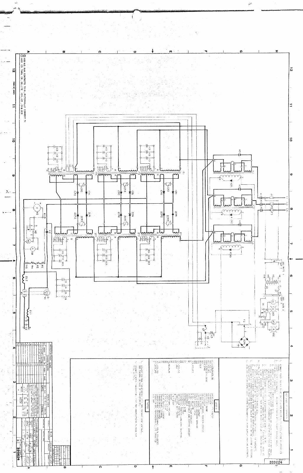
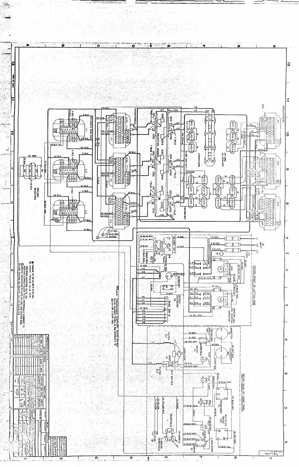
HOBART DIAGRAMS Connection and Schematic, 5918A-1
Connection and Schematic,
Outline Dimension
Connection,
5918A-2
5918A-3
Contents Jan 18179 I Page 4 Revised Aug 31/79

1.
2.
3.
4.
TN-687
CHAPTER 1. DESCRIPTION/OPERATION
SECTION 1. DESCRIPTION
General
The power supplies covered in this manual are manufactured by Hobart Brothers Company, Power Systems Division, Troy, Ohio 45373, U.S.A.
Refer to Figure 1. Thbipnits are 28.5 Volt DC solid state power supplies equipped with ferroresonant circuitry (Patent Pending) and designed to be used for aircraft starting and to supply regulated 28.5 Volt DC power for operation of a parked aircraft's electrical equipment when the on-board' generator is not running.
Identification
Each unit has an identification plate on the control panel. This plate displays the unit's specification, model and serial numbers. Only the specification number completely identifies the type of machine. There can be several units with the same model number, each with slight'differ- ences in construction, etc. Each of these machines will have a different specification number. The specification number consists of two parts: a four-digit series number which may or may not have an alphabetical suffix, followed by a dash number (e.g. 5918A-1). No specification number is complete without both parts. The serial number identifies individual units.
Specification number 591811-l identifies a unit requiring 230/400 V AC, 50 Hz input. Specification number 5918A-2 identifies a unit requiring 208/ 240/480 V AC, 60 Hz input. Complete performance specifications for all machines are listed in Figure 2. Both are constant voltage machines with adjustable current limiting capabilities. In the current limiting mode, aircraft starting current is adjustable from 750 to 1500 Amperes. Both machines are capable of delivering 400 Amperes continuously.
Orientation
Throughout the manual, reference to front and rear, left and right, assume that the viewer is facing the control panel end of the unit. The orienta- tion puts the control panel at the FRONT and has the input cables entering the LEFT side.
Special Features
A. Ferroresonant Circuitry
The ferroresonant circuitry automatically regulates the output voltageto hold it within 2% of the nominal 28.5 Volts DC, independent of :'I 10% change in line voltage and from no load to full load (400 Amperes DC).
B. Convection Cooling
The convection cooling feature of these power supplies insures quiet operation as well as adequate heat dissipatson. In addition, this system is cleaner and more reliable than any forced-air system. Cooling air is drawn in through openings in the base plate, circulated over the components and expelled through the louvered openings in all four panels of the canopy. The system is most efficient when all four panels and the top are in place.
Jan 18/79 Revised : Aug 31179
l-l Page 1

8 I--’
rt
x
-

Specifications
Model Number
Nominal Output Voltage
Amperes (Continuous)
Amperes (Starting)
Input Voltage (AC)
Line Amps (at 400 Amps output)
Line Amps (at1500Amps output intermittent)
Line Regulation
Load Regulation
Ripple no load
Ripple full load
RF1
Efficiency
Power Factor
Convenience Receptacle
Length
Width
Height, Including Trailer
Weight
1 1
59188-l (50 Hz Input)
TM-687 -
5918A-2 (60 Hz Input)
5FR28-400CL
28.5 Volts DC
400
750 to 1500 Adjustable
230/400
48127.5
6FR28-400CL
28.5 Volts DC
400
750to 1500 ,Adjustable
208/240/480
53148124
144183 159/144/72
Output voltage held to f&%with ?lO%input change
Output voltage held to 2 2% no load to full load (400 Amps)
Output voltage held tc f%%with f 10% input change '
Output voltage held tc +l%%no load to full load (400 Amps)
.% l%% RMS
Below limits of MIL- STD-461A
%
l$% RMS
Below limits of MIL- STD-461A
80% at full load (400 80% at full load (400 Amperes) Amperes)
95% at full load (400 Amperes)
230 Volts, 50 H&iso- lated fuse protected
46 inches (1168 mm)
35 inches (889 mm)
96% at full load (400 Amperes) ,
115 Volts, 60 Hz,iso- lated fuse protected
46 inches (1168 mm)
35 inches (889 mm)
47inches (1194 mm) 47inches ('1194 mm)
1700 pounds (771 kg) 1575 pounds (71‘5. kg)
Specifications and Capabilities Figure 2 (Sheet 1 of 2)
Jan 18/79
Nov lo/81 Revised Page 3

TM-687
, ’ ’ VOLTAGE 30
1 I.
t
\
26 \ ‘- ’
\ \ I
24 I I I
Minimum i 22 .
-1 I
20 I .‘,
I
I
18 I I I - Range Of Adjustment B
0 I I
0 200. 400 600 800 1000 1200 1400 1600 1800 2000
OUTPUT CURRENT (AMPS)
STARTING AMPERES VERSUS TIME 1600
I I I I
800
600
Continuous Rating
400 Amps
TIME (SEC)
[4-5918*1
Specifications and Capabilities Figure 2 (Sheet 2 of 2)
i-l Page 4
Jan 18/79

TM-687
C. RF1 Suppression
The output circuit is prevented from radiating radio-frequency inter- ference by a filter network consisting of two inductors and two capacitors. The resulting suppression keeps RF1 below the limits established by MIL-
7 TD-461A 'I
D. Input and Output Contactors
Contactors in the input and output circuits provide a convenient means of opening and closing those circuits. They are controlled by the input and output switches (1 and 8, Fig. 6) and are monitored by indicator lights (2 and 7).
E. Portable Mounting (Trailer)
Each power supply is mounted on a four-wheel equipped with a drawbar and parking brake. The wheels rotate on roller bearings and have solid rubber tires. The parking brake is set by raising the drawbar to the vertical position. This trailer is furnished in kit form and is identified by Hobart Part Number 484359.
5. Detailed Decription
A. Canopy
A sheet metal enclosure (canopy) provides protection for the internal components. Two lifting eyes project through the side panels to facilitate handling with a crane or hoist. Side and end panels have rows of louvered openings to accommodate the free circulation of air required for the convection cooling of the internal components'. The top cover has overhanging 'flanges, tapered downward over the side panels, which provides a degree of protection from the weather.
An optional weatherproof housing is available for units which will be exposed to the elements without protection. This enclosure has no ventilating louvers in the side and end panels. However, the top cover is equipped with baffles which make the enclosure rainproof, while permitting the free flow of air required for the convection cooling process. This optional weatherproof enclosure replaces the standard enclosure and is available from Hobart Brothers Company as Part Number 399609. Installation of this optional enclosure increases the overall height of the power supply by 7 inches (178 mm).
B. Power Supply Components
The basic power circuit is silicon diode type with ferroresonant transformers. The ferroresonant transformer circuit automatically regulates the output voltage to hold it within approximately 2'2% of the nominal 28.5 Volts DC, independent of & 10% change in line voltage and from no load to full load (400 Amperes DC). The power supply assembly consists of the following functional groups of components:
Jan 18179
Revised : Aug 31179
l-l Page 5

TM-687
(1) Ferroresonant banks
Refer to Figure 3. There are two banks of transformers; the front three are wye connected and the rear three are delta connected. The rectif'ed outputs of both banks are connected in parallel and wired t hirough the output contactor and RF1 filter to the output terminals.
(2) Rectifier bank
A rectifier bank (Figure 4) consisting of 12 silicon diodes mounted on two flat heat sinks, is located below the interior panel. These diodes convert the AC output of the ferroresonant transformers to the required 28.5 Volts DC power supply output. Six suppressors, mounted on the top edge of the rectifier assembly mounting bracket, protect the diodes from voltage spikes that might damage them.
r-1. Page 6
Jan 18/.79

TM-687
1. Front Panel 6. Rear Transformers
2. Interior Panel 7. Rectifier Bank
3. Lifting Eyes 8. Capacitor Bank
Transformers
4. Terminal Board 9. Front
5. Reactors
Power Supply Components Figure 3
l-l Page 7
Jan 18/79

TM-687
1. Suppressor Assembly (6 Required) 2. Silicon Diode, 150 Amp (12 Requi 3. Heat Sink (2 Required) 4. Mounting Bracket
Rectifier Bank Figure 4
red)
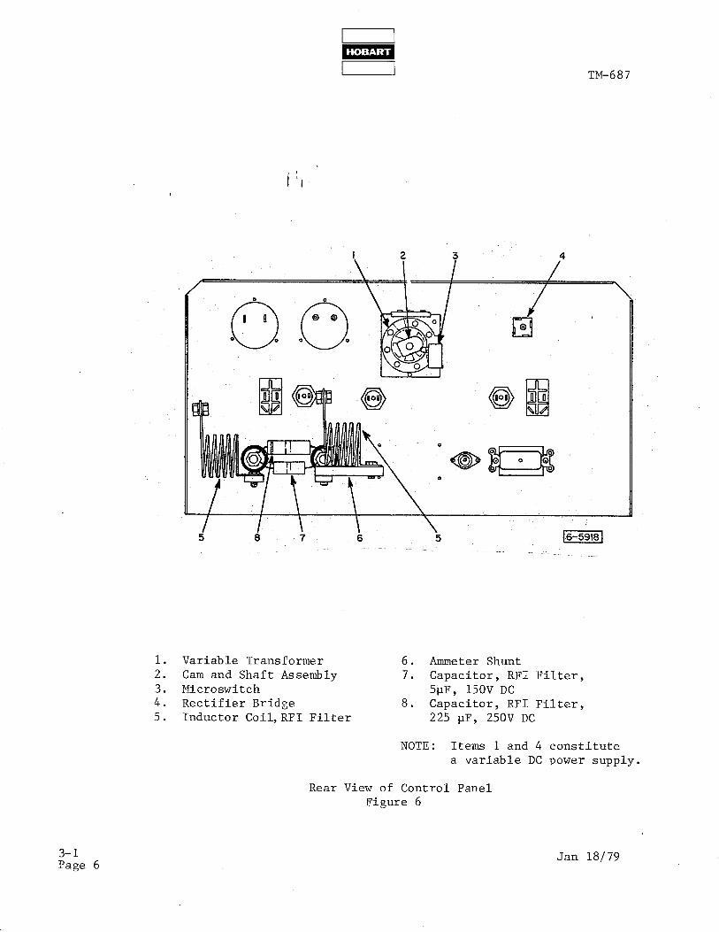
1. ~,. Variable Transformer 6. Ammeter Shunt
2. Cam and Shaft Assembly 7. Capacitor, RF1 Filter, 3. Microswitch 5pF, 150 V DC 4. Rectifier Bridge 8. Capacitor, RF1 Filter, 5. Inductor Coil, RF1 Filter 225 yF, 250 V DC
Note: Items 1 and 4 constitute a variable DC power supply.
Rear View of Control Panel Figure 5
l-1 Page 8
Jan 18/79

id - . - Fl TM-687
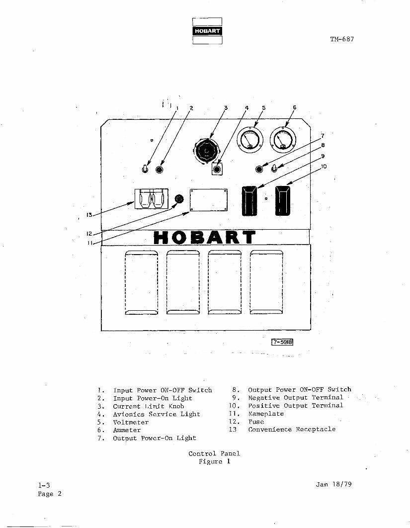
1. Input Power ON-OFF Switch 8. 2. Input Power-On Light 9. 3. Current Limit Knob 10. 4. Avionics Service Light 11. '5. Voltmeter 12. 6. Ammeter 13. 7. Output Power-On Light
7
8
9
IO
Control Panel Figure 6
Output Power ON-OFF Switch Negative Output Terminal Positive Output Terminal Nameplate Fuse Convenience Receptacle
Jan 18/79‘ l-l Page 9

TM-687
(3) Reactor bank
These three saturable reactors have their load coils wired in series with the primary circuits of the ferroresonant transformers. The control coils on the saturable reactors are wired in series and cpnnected to a variabld QC power supply (1 and 4, Fig. 5) controlled by the, CURRENT LIMIT knob on the front panel (3, Fig. 6). With the knob set to the extreme counterclockwise position (750 Amperes), the control current is nearly zero and the reactor load coils will support much of the line voltage, thus reducing the voltage to the tranformer primary circuit. This reduction in primary voltage causes the maximum output current to be limited to approximately 750 Amperes. When the CURRENT LIMIT knob is set to AVIONICS SERVICE (1500 Amperes), the reactor load coils are shorted out, thus allowing all of the line volt- age to be impressed across the transformer primary circuit. With full line voltage on the primary circuit, the output will be maximum: ' approximately 1500 Amperes. Also, when the CURRENT LIMIT knob is in the AVIONICS SERVICE mode, the rectifier control circuit is turned off and the AC receptacle on the front panel will furnish AC power. With the CURRENT LIMIT knob in any other position the receptacle is turned off and variable control power is furnished to the reactor control coils. Variable control power on the reactors results in variable voltage drop on reactor load coils and hence variable transformer primary voltage. By varying transformer primary voltage between some low value and maximum, the current limit is varied between 750 Amperes and the maximum value of 1500 Amperes.
(4) Controls and indicators circuits
A control transformer (3,Fig 7), connected to the input line, reduces input voltage to 115 Volts AC for operation of the INPUT power indicator lamp (2, Fig. 6), input contactor (4, Fig. 7) and powers the AVIONICS SERVICE mode indicator lamp (4, Fig. 6), the current limit switch (3, Fig. 5>, and the reactor load coil shorting contactor (8, Fig. 7). The output controls and indicators: ammeter (6, Fig 6), voltmeter (5), OUTPUT indicator lamp (7), and output load contactor (6, Fig. 7) are powered directly from the 28.5 Volt DC output line.
l--l Page 10
Jan 18/79

TM-687
\ IO
1. Ground Stud 6. Output Contactor 2. Line Fuses 7. Auxiliary Switch (N-C.) 3. Control Transformer 8. Reactor Load Coil Shorting 4. Input Contactor Contactor 5. Auxiliary Switch (N.O.) 9. Auxiliary Switch (N.O.)
10. Fuse, 0.6 Amp.
Jan 18/79
Interior Panel Figure 7
l-l Page 11

w TM-687
C. 5918A-3
Specification Number 5918A-3 identifies a unit which is similar to 59188-Z except for the input voltage which is 575 volts, AC. Figure 8 lists speci- fications and capabilities for this unit. Internal component differences are covered in the Ill&bated Parts List, Chapter 4.
l-l Page 12 Aug 31179

‘& I 1 TM-687
Specifications (605;:8$&t)
Model Number i 6 6FR28-400CL
Nominal Output Voltage 28.5 Volts DC
Amperes (Continuous) 400
Amperes (Starting) 750 to 1500 Adjustable
Input Voltage (AC) 575
Line Amps (at 400 Amps output) lg
Line Amps (at1500Amps output intermittent) 60
Line Regulation Output voltage held tl ?$%with f 10% input change
Load Regulation Output voltage held t *l$%no load to full .load (400 Amps)
Ripple no load 10 !z
Ripple full load 1% RMS
RF1 Below limits of MIL- STD-461A
Efficiency 80% at full load (400 Amperes)
Power Factor 96% at full load (400 Amperes)
Convenience Receptacle 115 Volts, 60 Hqiso- lated fuse protected
Length 46 inches (1168 mm)
Width 35 inches (889 mm)
Height, Including Trailer 47 inches (1194 mm) Weight 1575 pounds (71.5 kg)
Specifications and Capabilities (5918A-3) Figure 8
Nov lo/81 Revised l-l
Page 13


TM-687
SECTION 2. PREPARATION FOR USE
1. Installation
A. Receipt of Equipment
Check the equipme& received against the shipping papers to make certain shipment is complete. Check the equipment for shipping damage. If the equipment has been damaged in transit, notify the carrier at once and file a claim for damages. If you require assistance with a damage claim or if ’ the shipment is in error, furnish full information to Hobart Brothers Com- pany at the address given in the Introduction of this manual.
Use care in uncrating to avoid damaging the equipment with tools. Use the lifting eyes to handle the unit with a crane or hoist.
B. Attach Trailer
The trailer assembly is shipped with the power supply but it is packaged separately in kit form. The kit, Hobart part number 484356, contains all trailer parts and all attaching hardware required to assemble the trailer to the power supply frame.
Refer to Figure 1. This figure illustrates the frame with the power supply removed for clarity only. Do not attempt to remove the frame to attach the trailer.
(1) Apply a coating of grease to the top surface of the fifth wheel on rear axle assembly (3) , then attach it to the rear support (2) with the 3/4 inch bolt, flat washe,r and nut (1, 4 and 5) . Secure with cotter pin (6) through bolt and nut.
(2) Raise the power supply with a crane or hoist using the lifting eyes. The unit weighs approximately 1700 pounds (771 kg). Support the unit properly under the frame, at a convenient working height, leaving the front and rear portions of the frame clear for attaching the trailer.
WARNING: DO NOT ATTEMPT TO WORK UNDER THE UNIT WHILE IT IS SUPPORTED BY THE LIFTING EYES.
(3) Attach the support, with the axle assembly attached, to the first two holes from the end on each side of the bottom flange at the REAR of the frame. Use four each of the 3/8 inch bolts, lock washers and nuts provided.
(4) Attach front axle (10) to the FRONT end of the frame bottom flange (first two holes from FRONT end on each side) using four each of the 3/8 inch bolts, nuts and lock washers provided.
(5) Attach all four wheels (7) with flat washers (8) and cotter pins (9) .
(6) Attach the brake assembly (18) to the rear axle assembly (3) with the screws, washers, spacers, and nuts (14, 15, 16, and 17) as shown in inset in Figure 1.
Jan 18179 l-2 Revised : Aug 31179 Page 1

I I TM-687
1. 2. 3. 4. 5. 6. 7. 8. 9.
10. 11.
Bolt, 3 I4 inch Mounting Plate Rear Axle Assembly Flat Washer, 3/4 inch Nut, 3/4 inch, slotted Cotter Pin, l/8 x 1 l/8 inch Wheel (4) Flat Washer, 1 inch (4) Cotter Pin, 3/16 inch (4) Front Axle Assembly Cotter Pin, l/8 x 1 inch
12. 13. 14. 15. 16. 17. 18. 19. 20. 21. 22.
Trailer Figure 1
Flat Washer, l/ 2 inch Brake Adjusting Rod Screw, l/4 inch (2) Flat -Washer, l/4 inch (4) Spacer Nut, KEPS, l/4 inch (2) Brake Assembly Nut, Lock, l/2 inch (2) Screw, 3/8 inch (8) Lock Washer, 3/8 inch (8) Nut, 3/8 inch (8)
l-2 Page 2 Revised :

w TM-687
(7) Attach the adjusting rod (13) to the eye welded on the drawbar with washer (12) and cotter pin (11). Make sure threaded end of rod (13) passes between the vertical plates under the fifth wheel, and through hole in spacer of brake assembly (18), with one nut (19) threaded onto the rod on eachQ side of the spacer.
. (8) ) Adjust nuts (19) i !I back and forth, as required, so that when drawbar is raised to its highest vertical position, the bar on the brake assembly deflects the rubber tire ONLY l/l6 to l/8 inch (2 to 3 mm). Too much , force against the tire will bend the brake.
C . Location
The power supply should be operated in locations free of high humidity, dust, high ambient temperature and corrosive fumes. Moisture condenses on electrical controls and components causing corrosion. Dust and dirt collects on components resulting in reduced efficiency of the convection cooling process.
At least six inches of space is needed on all four sides of the unit to insure free circulation of air. Make sure that the ventilating louvers in the canopy are not obstructed.
D. Input Power Connections
Remove the top cover to expose the internal components. Find the CAUTION label on the interior panel. This label shows the input voltage for which the unit was wired at the factory. Refer to the AC INPUT label on the interior panel. This label provides instructions for changing the internal wiring and fuses if the voltage to be used is different from the voltage for which the unit was wired. Refer to Figure 2. Make the wiring changes and change the fuses as required.
5918A-3 takes 575 volts AC only. No voltage changeover is possible.
Voltage Changeover Connections Figure 2
Jan 18179 Revised : Aug 31179
l-2 Page 3
I i- i! i
I c !
t 5
TM-687
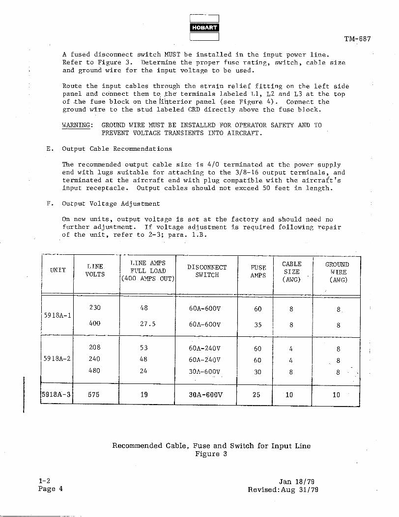
A fused disconnect switch MUST be installed in the input power line. Refer to Figure 3. Determine the proper fuse rating, switch, cable size and ground wire for the input voltage to be used.
Route the input cables through the strain relief fitting on the left side panel and connect them to the* terminals labeled Ll, L2 and L3 at the top of the fuse block on the iihterior panel (see Figure 4). Connect the ground wire to the stud labeled GRD directly above the fuse block.
WARNING: GROUND WIRE MUST BE INSTALLED FOR OPERATOR SAFETY AND TO PREVENT VOLTAGE TRANSIENTS INTO AIRCRAFT.
E. Output Cable Recommendations
The recommended output cable size is 4/O terminated at the power supply end with lugs suitable for attaching to the 3/B-16 output terminals, and terminated at the aircraft end with plug compatible with the aircraft's input receptacle. Output cables should not exceed 50 feet in length.
F. Output Voltage Adjustment
On new units, output voltage is set at the factory and should need no further adjustment. If voltage adjustment is required following repair of the unit, refer to 2-3; para. l.B.
LINE LINE AMPS UNIT
VOLTS FULL LOAD (400 AMPS OUT;
I
230 48 5918A-1
400 27.5
208 53
j918A-2 240 48
480 24
918A-3 575 19
DISCONNECT SWITCH
6OA-6OOV
6OA-6OOV
60A-240V
60A-i40V
3OA-600V
30A-600V
FIJSF ' CABLE GROUND 1 AMPS
SIZE WIRE (AwG) (AWG)
60 4 8
60 4 8
30 8 8
25 I
10 I
10 I I
Recommended Cable, Fuse and Switch for Input Line Figure 3
l-2 Page 4
Jan 18179 Revised:Aug 31179

TM-687
Interior Panel -7
Fuse Block 7
Ground Stud
I
/ \
0 0 GRD
\
Input Line Connections Figure 4
l-2 Jan 18179
Page 5

.

TM-687
SECTION 3. OPERATION
1. General
2.
A. Place the trailer-mounted unit in a convenient and safe position near the aircraft to be serviced. Be sure to set the parking brake.
' B. Make sure that thej h ower supply is connected to a source of AC input power as outlined in l-2: para l.D.
C. Connect the output cables to the aircraft.
CAUTION: BEFORE POWER DELIVERY, MAKE SURE AIRCRAFT BATTERIES ARE DISCONNECTED. THIS POWER SUPPLY IS NOT A BATTERY CHARGER. WITH THE BATTERIES SUPPLYING CURRENT IN ADDITION TO THE POWER SUPPLY, SERIOUS DAMAGE TO ON-BOARD ELECTRICAL EQUIPMENT MAY OCCUR.
Operation
A.
B.
C.
D.
E.
Refer to Figure 1. Raise INPUT switch (1) to ON position. Amber INPUT light will glow indicating that input contactor has closed and that AC power is being supplied to the machine. Release switch to RUN position. Voltmeter (5) will indicate approximately 29 Volts DC.
Position CURRENT LIMIT control (3) fully clockwise to 1500 position. Amber AVIONICS SERVICE light (4) will glow indicating that the unit is constant-voltage, electronic service mode. This position is also used when 1500 Amperes starting current is required.
NOTE: 1. Output voltage regulation is most constant in this mode.
2. AC voltage is present at receptacle connector (13) ONLY in this mode.
If reduced starting current is required, turn CURRENT LIMIT control counterclockwise to required amperage marked on panel.
Raise OUTPUT switch (8) to ON position. Green OUTPUT light (7) will glow indicating that output contactor has closed and that the aircraft is receiving DC power. Release switch to RUN position. Ammeter (6) will indicate the DC current being delivered to the aircraft.
At the end of the power delivery run, p osition the OUTPUT switch to OFF. Green light will go out indicating that the output contactor has opened and that the DC power is no longer being delivered to the aircraft.
Position INPUT switch to OFF. Amber INPUT light will go out indicating that input contactor has opened and that AC power is no longer being supplied to the unit.
CAUTION: DO NOT DISCONNECT OUTPUT CABLES FROM AIRCRAFT WHILE POWER IS BEING DELIVERED. OPENING CONNECTOR UNDER LOAD WILL CAUSE ARCING AND PITTING OF CONNECTOR PARTS.
Jan 18/79 l-3 Page 1
TM- 6 8 7
HOBART
1. Input Power ON-OFF Switch 8. Output Power ON-OFF Switch 2. Input Power-On Light 9. Negative Output Terminal 3. Current Limit Knob 10. Positive Output Terminal 4. Avionics Service Light 11. Nameplate 5. Voltmeter 12. Fuse 6. Ammeter 13 Convenience Receptacle 7. Output Power-On Light
l-3 Page 2
Control Panel Figure 1
Jan 18/79

TM-687
CHAPTER 2. SERVICE
SECTION:.l. MAINTENANCE
1. General
iI, * '?here,are no high-mortality components inthe power supply requiring periodic replacement. The only scheduled maintenance recommended for the power supply is cleaning the internal components and lubrication of the trailer wheel bearings.
A. Cleaning
WARNING: BEFORE CLEANING THE INTERIOR OF THE POWER SUPPLY, MAKE SURE INPUT POWER IS OFF. SHORT-CIRCUIT EACH CAPACITOR WITH AN INSULATED SCREWDRIVER. OTHERWISE, LETHAL ' ELECTRICAL SHOCK HAZARD EXISTS.
At least every three months, or more often if necessary, clean out all dust and dirt that may have accumulated inside the unit. Use clean, dry, compressed air at a pressure not exceeding 25 psi (172 kPa). Use a hand bellows if compressed air is not available. Wipe components, as required, with a clean, soft, lint-free cloth.
B. Lubrication
Lubricate the trailer wheel bearings semiannually or after 800 hours of operation. Wheels are equipped with high-pressure grease fittings. Use grease conforming to the requirements of Military Specification MIL-G-10924B or equivalent.
(1) Wipe dirt from grease fittings with a clean cloth.
(2) Place pressure gun securely on fitting. Apply pressure until old grease is forced out and new grease appears. This will insure that grease cavity has been filled with clean grease and that old, contaminated grease has been forced out.
Jan 18/79 2-l Page 1


TM-687
SECTION 2. INSPECTION/CHECK
1. General
The power supply requires a minimum of scheduled inspection and checking. Scheduled inspection periods of less than one year are not required; however, a visual inspection of the components is recommended each time the top cover is removed. i 'I
WARNING: BE SURE DISCONNECT SWITCH IS OPEN AND DISCHARGE ALL CAPACITORS WITH AN INSULATED SCREWDRIVER. OTHERWISE, LETHAL ELECTRICAL ' SHOCK HAZARD EXISTS.
A. Inspect all lead connections for security.
B. Inspect all components and connections for discoloration and evidence of overheating.
C. Inspectandcheck all attaching hardware for security.
D. Check transformer hardware for security to avoid magnetic rattle.
E. Inspect all fuses and lamp bulbs. Refer to Figures 1 and 2 for replacements.
ILLUSTRATION SIZE AND TYPE
Transformers/
Transformer Type: Slow-Blow I i
Receptacle and Control Panel l-3; Figure 1 Control Circuit
5 Amperes (5918A-1)
i
15 Amperes (5918A-2,-3) / Type: Slow~Blow
1
Fuse Identification Chart Figure 1
~GHTIDENTIFICATION LOCATION MANUFACTURER / PART NUMBER
Input Control Panel Sylvania 120 MB I I
I output , Control Panel General Electric I
313 I
1 Avionics Service Control Panel I
Sylvania ! 120 MB /
Lamp Identification Chart
Jan 18/79 Figure 2
2-2 Revised : Aug 31179 Page 1


TM-687
SECTION 3. ADJUSTMENT/TEST
1. Adjustment
WARNING: BEFORE MAKING ANY ADJUSTMENTS, TURN OFF DISCONNECT SWITCH, REMOVE LINE FUSES AND DISCHARGE EACH CAPACITOR WITH AN INSULATED SCREW- DRIVER. OTHFRFISE, LETHAL ELECTRICAL SHOCK HAZARD EXISTS.
A. Input Voltage Changeover
If the power supply input voltage is changed for any reason, follow the instructions outlined in l-2; para l., D. Make sure that ALL THREE front transformers, ALL THREE rear transformers and ALL THREE reactors are connected identically. Make sure that line fuses are changed per instructions.
B. Output Voltage Adjustment
Outputvoltageadjustment is necessary if the open circuit voltage goes above 29 Volts DC or if the voltage drops below 27.9 Volts DC at 400 Amperes load. Before making any adjustments, make sure that bad connec- tions or damage to the power supply is not affecting the output voltage.
(1)
(2)
(3)
(4)
Locate output voltage adjustment label on the interior panel (same as Figure 1). Factory setting is indicated on this label by circles around terminal numbers to which YELLOW jumpers and ORANGE leads were connected. . . Locate YELLOW jumper and ORANGE lead on each transformer terminal block.
Mark present location of YELLOW jumper and ORANGE lead on label if different from factory setting.
Reconnect YELLOW jumper and ORANGE lead to the terminals, giving the desired change in output voltage. ALL THREE front transformers must be connected identically and ALL THREE rear transformers must be connected identically.
CAUTION: CHANGE CONNECTIONS ON BOTH BANKS OF TRANSFORMERS SIMULTA- NEOUSLY, ONE STEP AT A TIME, OBSERVING EFFECT ON OUTPUT VOLTAGE AFTER EACH CHANGE. DO NOT CHANGE CONNECTIONS ON REACTORS.
C. Current Limit Adjustment
Refer to Figure 2. Slippage of shaft and cam assembly (2) or replacement of variable transformer (1) or microswitch (3) will require adjustment of assembly as follows:
(1) Loosen two setscrews in wiper of variable transformer (1) and posi- tion wiper by hand to full counterclockwise position (viewing rear of control panel).
(2) Adjust horizontal position of microswitch (3) to assure alignment of switch actuator arm and cam (2).
(3) Rotate cam counterclockwise by hand until it actuates microswitch. Tighten setscrews loosened in step (1) above to secure wiper to shaft.
Jan 18/79 2-3 Page 1

TM-687
NOTE: In full CLOCKWISE position, the cam may deflect the switch actuator arm. Make sure that it does not actuate the switch in the CLOCKWISE position.
(4) Loosen two setscrews in transformer control knob (front of control panel). Position control knob pointer to AVIONICS SERVICE position
. and tighten setscrew 6' It0 secure it.
OUTPUT VOLTAGE ADJUSTMENT
THE OUTPUT VOLTAGE IS FACTORY SET WITH CONNECTIONS-CIRCLED BELOW. ATTEMPTADJUSTMENT ONLY AFTER DETERMINING NO OTHER PROBLEMS EXIST. CHANGE CONNECTIONS ON BOTH BANKS OF TRANS- FORMERS SIMULTANEOUSLY,.ONE STEP AT A TIME, OBSERVING EFFEC’ ON OUTPUT VOLTAGE AFTER EACH CHANGE. OUTPUT VOLTAGE SHOULD NOT EXCEED 29 VOLTS. ALL THREE FRONT TRANSFORMERS MUST BE IDENTICALLY CONNECTED AND ALL THREE REAR TRANSFORMERS MUST
BE IDENTICALLY CONNECTED.
IORANGE-WHITE LEADMUST REMAIN ON 7
CONNECTION FOR MINIMUM OUTPUT SHOWN.
NOTES :
1. DO NOT CHANGE CONNECTIONS ON TERMINALS 7 THRU 12 ON REACTORS (WHEN USED).
2. FRONT TRANSFORMERS NEAR CONTROL PANEL.
405044
FRO
YELLOW JUMPER
a TO 9 a TO 10 a TO 9 a TO 10 a TO 9
i Ji y:,
a TO 11 a TO 12 a TO 12
Nl
I !EP
I
--.-.A YELLOW JUMPER --
a TO 9
i Ti ;”
i Ti ;” 8 TO 9
ii: 17 8 TO 11
. TRANS
ORANGE LEAD
TO 12
;: 1: TO 11 TO 10 TO 8 TO 9 TO 10 TO 9 TO 10 TO 9
iR TRAI ORANGE
LEAD TO 12 TO 12 TO 11 TO 11
;: i” TO 9 TO 10 TO 9 TO 10 TO 9
RMERS OUTPUT
VOLTAGE MAX I MUM OUTPUT
FORMERS OUTPUT
VOLTAGE MAX IMUM OUTPUT
1
Output Voltage Adjustment lpiaiiq
Figure 1
2. Test
A. Silicon Diodes
(1) Disconnect diode leads.
(2) Use a good quality ohmmeter (preferably one having a mid-scale value of approximately 50 ohms) to measure resistance values.
(3) Zero the instrument on the R X 1 scale.
(4) Take and note a reading by placing either ohmmeter lead on the threaded end of the diode and the other lead on the diode lead.
(5) Reverse the ohmmeter leads on the diode, take and note another reading.
2-3 Page 2
Jan 18/79

TM-687
1
I 2 3 4
\ I / /
I
0 I 0 0 0 0
1. Variable Transformer 6. Ammeter Shunt 2. Cam and Shaft Assembly 7. Capacitor, RF1 Filter; 3. Microswitch 5pF, 150V DC 4. Rectifier Bridge 8. Capacitor, RF1 Filter 5. Inductor Coil RF1 Filter 225pF, 250V DC
NOTE: Items 1 and 4 constitute a variable DC power supply.
Rear View of Control Panel Figure 2
Jan 18/79 2-3 Page 3

TM-687
(6)
(7).
B. Transient Suppressors
(1)
(2)
(3)
(4)
(5)
Disconnect one lead of suppressor.
Use good quality ohnnneter on R X Ior R X 100 scale.
Take and note an ohmic reading of the suppressor.
Reverse the test leads and take and note another reading.
The readings should be similar (within 20%) and of a relatively high value.
(6) If the meter indicates either infinity or a very low reading, replace the suppressor.
The diode may generally be considered good if:
One reading is infinite or very high.
The other reading is extremely low.
An acceptable low O$-I$C value or range cannot be given because ohm- meter readings may vary between meters, or even between diodes with the same rating.
NOTE: Ifit isnecessarytoreplace one or more diodes, apply Burndy Penetrox, or equivalent heat sink compound, to mating surfaces of diode and heat sink. Compound should be visible at edges of diode flange. Do not apply compound to screw threads. Torque diodes to 20 to 25 foot-pounds (27 to 34 N*,m).
C. Capacitors
(1) Use an insulated screwdriver to short circuit each capacitor.
(2) Disconnect capacitor and apply leads of suitable ohmmeter (set' to highest scale) to capacitor terminals.
(3) If capacitor is good, pointer will deflect indicating capacitor is being charged followed by a deflection in the opposite direction indicating partial discharge.
(4) If there is no deflection, capacitor is open and must be replaced. If meter needle moves and stops at one value, replace capacitor.
2-3 Page 4
Jan 18/79

TM-687
CHAPTER 3. TROUBLESHOOTING
SECTION 1. PROCEDURE
1. General
A. Troubleshooting is /a\~ orderly process of checking and eliminating possible causes of trouble until the exact cause is found. The best place to start is at the source of power. Continue testing and checking the cir- cuit, step by step,,in an orderly manner, until the cause of trouble is 1 located. Refer to the schematics and connection diagrams in Chapter 6.
B. This section provides information useful in diagnosing and correcting troubles which cause unsatisfactory operation or failure of the equipment.
C. Minor troubles may be remedied by the operator; however, major repairs must be done by experienced electricians only.
2. Troubleshooting Chart
A. * Description
The troubleshooting chart lists information under three headings:
(1) Trouble, symptom and condition
(2) Probable cause
(3) Test, check and remedy
B. Use
The troubleshooting chart makes it possible to go directly to the source of trouble without checking an entire circuit. If trouble cannot be located by use of the chart, the only alternative is to check the affected circuits completely.
(1)
(2)
(3)
3. Safety
WARNING:
CAUTION
Find the trouble, symptom or conrlition in the first column.
Probable cause is listed in the second column.
Perform the test, check and remedy listed in the third column.
BEFORE WORKING ON THE EQUIPMENT, MAKE SURE INPUT POWER IS OFF AND DISCHARGE EACH CAPACITOR WITH AN INSULATED SCREWDRIVER. OTHER- WISE, LETHAL ELECTRICAL SHOCK HAZARD EXISTS.
DO NOT APPLY A MEGGER OR ANY HIGH POTENTIAL TEST EQUIPMENT IN ANY MANNER THAT SUBJECTS THE SILICON DIODES AND OTHER COMPONENTS TO ABNORMAL VOLTAGES. SILICON DIODES MUST BE ISOLATED OR SHORTED WITH EXTREMELY SHORT LEADS. SUCH TESTS MUST BE MADE UNDER THE SUPERVISION OF A FACTORY REPRESENTATIVE.
Jan 18179 3-l Page 1

TM-687
\ IO
1. Ground Stud 6. Output Contactor 2. Line Fuses 7. Auxiliary Switch (N.C.) 13 . Control Transformer 8. Reactor Load Coil Shorting Contactor 4. Input Contactor 9. Auxiliary Switch (N.O.) 5. Auxiliary Switch (N.O.) 10'. Fuse, 0.6 Amp
3-l Page 2
Interior Panel Figure 1
Jan 18/79

TI\l-687
A.C. INPUT THIS MACHINE MAY BE RECONNECTED FOR
THIS MACHINE MAY BE RECONNECTED FOR ALTERNATE INPUT VOLTAGE LISTED ON SERlAL NAMEPLATE. RECONNECTING INSTRUCTIONS ARE SHOWN BELOW. DIAGRAM SHOWS 400 VOLT CONNECTION. ALL SIX TRANSFORMERS AND THREE REACTORS (WHEN USED) MUST BE I;EyTICALLY CONNECTED. FAILURE TO f L OW INSTRUCTIONS Wl.U RESULT IL
ONENT OAMAGF.
230 VOLTS 400 VOLTS
. TRANSFORMERS AND REACTORS (WHEN USED) RED JUMPERS
1. TRANSFORMER? AND REACTORS (WHEN USED) ‘RED JUMPERS
FROM TERMINAL 1 TO 4 AND FROM TERMINAL 2 TO 5. AND 3 TO 6.
!. CONTROL TRANSFORMER - 2. CONTROL TRANSFORMER - CONNECT PER INSTRUCTION ON CONNECT PER INSTRUCTION 0 TRANSFORMER FOR 230 YOLTS. TRANSFORMER FOR 400 VOLTS
I. AC INPUT FUSE(S) - “,“‘A”” 3. AC INPUT FUSE(S) - RATING INDICATED FOR LOW V LT GE INOiCATED FOR HIGH VOLTAG ON LABEL NEAR FUSES. ON LABEL NEAR FUSES.
AND REACTORS (WHEN USED) RED JUMPERS FROM TERMINAL 1 TO 5 AND 2 TO 6. 2. CONTROL TRANS- FORMER CONNECT PER INSTRU TION ON TRANSFORME FOR 240 VOLTS. 3. AC FUSES--SEE BELOW.
. , . 240 VOLTS 480 VOLTS
1. TRANSFORMERS 1. TRANSFORMERS AND REACTORS (WHEN AND REACTORS (WHEI USED) RED JUMPERS USED) RED JUMPERS FROM TERMINAL 1 TO FROM TERMINAL 3 T( 4 AN0 3 TO 6. 4. 2. CONTROL TRANS- 2. CONTROL TRANS. FORMER FORMER CONNECT PER INSTRUC CONNECT PER INSTR\ TION ON TRANSFORMER TION ON TRANSFORM1 FOR 240 VOLTS. FOR 480 VOLTS. 3. AC FUSES--SEE 3. AC FUSES--SEE BELOW. BELOW.
Suppressor Assembly (6 Required) Silicon Diode, 150 Amp (12 Required) Heat Sink (2 Required) Mounting Bracket
Rectifier Bank Figure 2
A. C. lNPUT
5918A-I 591EA-2
NOTE : 59188-3 uses 575 volts AC only. No voltage changeover is possible.
Voltage Changeover Connections Figure 3 ~~
Jan 18179 3-l
Revised: Aug 31/79 Page 3

TM-687
3-l Page 4
1. Input Power ON-OFF Switch 2. Input Power-On Light 3. Current Limit Knob 4. Avionics Service Light 5. Voltmeter 6. Ammeter 7. Output Power-On Light
8. Output Power ON-OFF Switch 9. Negative Output Terminal 10. Positive Output Terminal 11. Nameplate 12. Fuse 13. Convenience Receptacle.
Control Panel Figure 4
Jan 18/79 Revised:Aug 31/79

Jan 18/79
I-
TM-687
1. Front Panel 6. Rear Transformers 2. Interior Panel 7. Rectifier Bank 3. Lifting Eyes 8. Capacitor Bank 4. Terminal Board 9. Front Transformers 5. Reactors
Power Supply Components Figure 5
3-l Page 5
I 1 TM-687
/ I \ \ \ 5 8 7 6 5
1. Variable Transformer 2. Cam and Shaft Assembly 3. Microswitch 4. Rectifier Bridge 5. Inductor Coil,RFI Filter
6. Ammeter Shunt 7. Capacitor, RFT Filter,
5yF, 150V DC 8. Capacitor, RF1 Filter,
225 pF, 250V DC
NOTE: Items 1 and 4 constitute a variable DC power supply.
Rear View of Control Panel Figure 6
3-l Page 6
Jan 18/79
TM-687
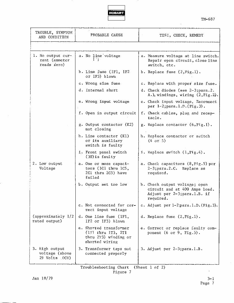
TROUBLE, SYMPTOM AND CONDITION
PROBABLE CAUSE TEST, CHECK, REMEDY
1. No output cur- a. No i ine'voltage II
a. Measure voltage at line switch rent (ammeter Repair open circuit, close line reads zero) switch, etc.
b. Line fuse (lF1, lF2 b. Replace fuse (2,Fig.l). or lF3) blown
c. Wrong size fuse c. Replace with proper size fuse.
d. Internal short d. Check diodes (see 2-3;para.2. A.), windings, wiring (2,Fig.2$.
e. Wrong input voltage e. Check input voltage, Reconnect per 1-2;para.l.D.(Fig.3).
f. Open in output circuit f. Check cables, plug and recep- tacle.
g. Output contactor (K2) g. Replace contactor (6,Fig.l). not closing
h. Line contactor (Kl) h. Replace contactor or switch or its auxiliary (4 or 5) switch is faulty
. 1. Front panel switch (3S)is faulty
i. Replace switch (l,Fig.4).
2. Low output Voltage
a. One or more capaci- a. Check capacitors (8+Fig.5)per tors (lC1 thru lC5, 2-3;para.2.C. Replace as 2Cl thru 2C5) have required. failed
b. Output set too low b. Check output voltage; open circuit and at 400 Amps load. Adjust per 2-3;para.l.B. if required.
c. Not connected for cor- c. Adjust per l-2;para.l.D.(Fig.3). rect input voltage
(approximately l/2 d. One line fuse (lF1, d. Replace fuse (2,Fig.l). rated output) lF2 or lF3) blown
e. Shorted transformer e. Correct or replace faulty com- (1Tl thru lT3, 2Tl ponent (6 or 9, Fig.5). thru 2T3) winding or shorted wiring
3. High output 3. Transformer taps not 3. Adjust per 2-3;para.l.B. voltage (above connected properly 29 Volts .ocv>
I Troubleshooting Chart (Sheet 1 of 2)
Figure 7
Jan 18/79 3-l Page 7

m TM-687
TROUBLE, SYMPTON AND CONDITION
PROBABLE CAUSE /
TEST, CHECK, REMEDY
4. Low cranking current
a. Cannot be increased above 750 Amps
b. Cannot be increased above approximately 1200 Amps
5. High cranking current. Can- not be adjusted below 1500 Amps
4. Faulty control cir- cuit
a. Blown fuse (3F) in control circuit
b. Reactor shorting contactor (K3) not closing
a.
b.
Reactor shorting contactor (K3) not opening
Current limit switch (4s) not opening when current limit knob is turned away from 1500 Amp position
4. Check and repair circuit as follows:
a. Replace fuse (12,Fig.4).
b. Check indexing of cam onswitcl (2 and 3,Fig.6). For procedure see 2-3;para.l.C. Check for voltage on contactor coil (8, Fig.1). Replace contactor if defective.
a. Check contactor (8,Fig.l). Replace if faulty.
b. Check switch (3,Fig.G).Replace if faulty. Adjust shaft and cam assembly (2) per 2-3;para. 1.c.
Troubleshooting Chart (Sheet 2 of 2) Figure 7
3-1 Page 8
Jan 18/79

I I
m
I 1 TM-687
CHAPTER 4. ILLUSTRATED PARTS LIST
SECTION 1. INTRODUCTION
General ii Th'e 111,ustrated Parts LX identifies, describes, and illustrates main
assemblies, subassemblies, and detail parts of two 28.5-Volt DC static, regulated power supplies manufactured by Hobart Brothers Company, Power Systems Division, Troy, Ohio 45373. These units are identified by.Specifica- tion numbers 5918A-1, 5918A-2 and 59188-3.
Purpose
The purpose of this list is to provide parts identification and descriptive information to maintenance and provisioning personnel for use in provisioning, requisitioning, purchasing, storing, and issuing of spare parts. 1
Arrangement
Chapter 4 is arranged as follows:
1.
2.
3.
4.
Section 1 - Introduction Section 2 - Manufacturer's Codes Section 3 - Parts List Section 4 - Numerical Index
Explanation of Parts List
A. Contents
The parts list contains a breakdown of the equipment into assemblies, sub- assemblies, and detail parts. All parts of the equipment are listed except:
(1) Standard hardware items (attaching parts) such as nuts, screws, washers, etc., which are available commercially.
(2) Bulk items such as wire, cable, sleeving, tubing, etc., which are also commercially available.
(3) Permanently attached parts which lose their identity by being welded, soldered, riveted, etc., to other parts, weldments, or assemblies.
B. Form
This form is divided into five columns. Beginning at the left side of the form and proceeding to the right, columns are identified as follows:
(1) FIGURE-ITEM NO. Column
Jan 18/79
Revised: Aug 31179
This column lists the figure number of the illustration applicable to a particular parts list and also identifies each part in the list by an item number. These item numbers also appear on the illustration. Each item number on an illustration is connected to the part to which it pertains by a leader line. Thus the figure and item numbering system ties the parts lists to the illustrations and vice versa. The figure and index numbers are also used in the numerical index to assist the user in finding the illustration of a part when the part number is known.
4-1 Page 1

I I
m
TM-687: i
(2) HOBART PART NUMBER Column
All part numbers appearing in this column are Hobart numbers. In all instances where the part is a purchased item, the vendor's identifying five-digit code and his part number will appear in the NOMENCLATURE column. Vendor parts vh;'ch are modified by Hobart will be identified as such in the NOMENCLAT ?JR E column. In case Hobart does not have an identifying part number for a purchased part, the HOBART PART NUMBER column will reflect No Number and the vendor's number will be shown in the NOMENCLATURE column. Parts manufactured by Hobart reflect no,vendor code or part number in the NOMENCLATURE column.
(3) NOMENCLATURE Column
The item identifying name appears in this column. Theindenturemethod is used to indicate item relationship. Thus, components of an assembly are listed directly below the assembly and indented one space. Vendor codes and part numbers for purchased parts are shown in this column.
(4) EFF (Effective) Column
This column is used to indicate the applicability of parts to different models of equipment. When more than one model of equipment is covered by a parts list, there are some parts which are used on only one model. This column is used for insertion of a code letter A,B, etc.., to indi- cate these parts and to identify the particular model they are used on. Uncoded parts are used on all units. Parts in this list are coded as follows:
Parts coded A are used on S5918A-1 only. Parts coded B are used on S5918A-2 only.
Parts coded C are used on S5918A-3 only.
(5) UNITS PER ASSEMBLY Column
This column indicates the quantity of parts required for an assembly or subassembly in which the part appears. This c6liZnn Jo& not n&%%stiFily reflect the total used in the complete end item.
4-1 Page 2

w 1
1 I TM-687
SECTION 2. MANUFACTURER'S CODES
1. Explanation
The following list is a compilation of vendor codes with names and addresses for suppliers of purchased parts listed in this publication. The codes are in accordance with the Federal Supply Codes for Manufacturers Cataloging Handbook H4-2, and are @Tanged in numerical order. Vendor codes are inserted in the Inomenclature column of the parts list directly following the item name and description. Suppliers without H4 codes are assigned five-position alpha codes which are listed at the end of the numerical list.
CODE VENDOR'S NAME AND ADDRESS
02231 Anchor Rubber Company 840 S. Patterson Blvd. Dayton, Ohio 45402
04713
05277
07793
10777
11450
11641
12855
Motorola Inc. Semiconductor Products Division Phoenix, Arizona 85008
Westinghouse Electric Company Semi d Conductor Dept. Youngwood, Pennsylvania 15697
Cornell-Dubilier Electic Corp. ' 13376 Beach Avenue Venice, California 90291
R. E. Condit Company 2601 South Dixie Highway Dayton, Ohio 45409
Electical Utilities Company 2427 S. Vincents Avenue La Salle, Illinois 61301
Furnas Electric Company c/o Walt Hammer & Associates P. 0. Box 376 Dayton, Ohio 45459
Marathon Special Products P. 0. Box 258 Bowling Green, Ohio 43402
Jan 18/79 4-2 Page 1

CODE
14101
15827
16023
44655
50603
58474
60741
71400
81091
81703
91929
4-2 Page 2
VENDOR'S NAME AND ADDRESS
Sprague Electric Company 300 W. National Vandalia, Ohio 45377
i 6 Micron Industries Inc. c/o Walt Hammer & Associates P. 0. Box 376 Dayton, Ohio 45459
Connectron Inc. c/o Walt Hammer & Associates P. 0. Box 376 Dayton, Ohio 45459
Ohmite Manufacturing Company 3601 W. Howard Street Skokie, Illinois 60076
H. B. Electrical Mfg. Company, Inc. 1125 National Pky. Mansfield, Ohio 44906
Superior Electric Company 383 Middle Street Bristol, Connecticut 06010
Triplett Electric Instrument Company Harmon Road Bluffton, Ohio 45817
Bussmann Manufacturing Division of McGraw & Edison Company 2526 W. University Street St. Louis, Missouri 63017
Pass & Seymour Inc. Solvay Station Syracuse, New York 13209
Mulberry Metal Products Inc. 2199 Stanley Terrace Union, New Jersey 07083
Honeywell Inc. Building Controls & Components Group Micro Switch Division Freeport, Illinois 61032
TM-687
Jan 18/79

I TM-687
SECTION 3. PARTS LIST
1. Parts List Arrangement
The parts list is arranged so that the illustration will appear on a left- hand page and the applicable parts list will appear on the opposite right- hand page. Unless the bi?t is unusually long, the user will be able to look at the,illustration and read the parts list without turning a page.
2. Symbols and Abbreviations
The following is a list of symbols and abbreviations used in the parts list.
k - Item not illustrated A, or AMP - ampere
AC - alternating current AR - as required DC - direct current
Fig. - Figure hd. - head hex - hexagon Hz - Hertz (cycles-per-second)
I.D. - inside diameter IN - inch
kVA - kilovolt-ampere I-IF - microfarad No. - number NHA - next higher assembly PRV - peak reverse voltage PSI - pounds per square inch Ref - reference (the item has been listed previously) TM - Technical Manual T-R - transformer-rectifier V- volt (when used as a prefix to a five-digit number,
vendor code) indicates
NOTE: An item which does not reflect an index number is an assembly which is not illustrated in its assembled state, or it is similar (right-hand, left-hand, top, etc.) to an item which is illustrated.
Jan 18/79 4-3 Page 1

TM-687'
Static Ground Power Unit Figure 1
4-3 Page 2
Jan 18/79

I I m
1 1 I TM-687
FIGURE HOBART ITEM NO. PART NO.
l-
1
2
*
5918A-1 59188-2 59188-3 No Number
484356
No Number
405390 405045 404054 404054 403247 405044 405622
NOMENCLATURE
1234567
STATIC GROUND POWER UNIT STATIC GROUND POWER UNIT
1s TATIC GROUND POWER UNIT
.
,.
.
.
.
.
.
.
.
.
‘CANOPY AND FRAME ASSEMBLY (for Details Fig. 2) KIT ,, PORTABLE, MOUNTING, ASSEMBLY (For Details See Fig. 2) INTERIOR GROUP (For Details See Fig. 5) LABEL, AC INPUT LABEL ,~ AC&NPgT LABEL, AC INPUT LABEL, CAUTION LABEL, CAUTION, CAP LABEL, OUTPUT VOLT. ADJ. LABEL, PATENT PENDING
UNITS per
EFF ASSY
A REF B REF c REF
REF
1
REF A 1 B 1
-C ~~ ,- 1- 1 2 1 1
Jan 18179 Revised : Aug 31179
4-3 Page 3

‘4 I
I 1
4-3 Page 4
, =o=i+ I:= - - -z =d=C .= - = =\t - -== -- 0000 / .- = =-- z-z = - = -* -L= s L-
l---i cco O0 00 0000
b-----l
1 .
‘-+ ,,-I //Jj i*
J -I IO II 12
Canopy and Frame Assembly Figure 2
Jan 18/79 Revised: Aug 31/79
TM-687

TM-687
NOMENCLATURE UNITS FIGURE HOBART per ITEM NO. PART NO. 1234567 EFF ASSY
2-
. 1 2 3 4 5 6
c 7 *
8
9
10
11
12
13 14
15 16 17 18
*
No Number CANOPY AND FRAME ASSEMBLY
l 399586 399590 . PANEL, SIDE, RIGHT 399591 PANEL, SIDE, LEFT 399523 : PANEL, REAR 399589 . PANEL, TOP 392098-17 LATH, SCREEN DW-4701A- 0 : BRACKET, CABLE w-10051-3 . CLAMP, WIRE PLASTIC 399530-4 PANEL, FRONT, ASSEMBLY
iF or Details See Fig. 3) 399530-3 PANEL, FRONT, ASSEMBLY
(For Details See Fig. 3) 399513-3 PANEL, INTERIOR, ASSEMBLY
iFor Details See Fig. 4) 399513-2 PANEL, INTERIOR, ASSEMBLY
iFor Details See Fig. 4) 399513-4 PANEL, INTERIOR, ASSEMBLY
iFor Details See Fig. 4) 484356 KIT, PORTABLE, MOUNTING,
’ ASSEMBLY 484233 . . AXLE, REAR, ASSEMBLY 484376 . . AXLE, FRONT, ASSEMBLY
(W/Tongue) 484238 . . BRACKET, MTG. FRONT 484236 . . BRAKE ASSEMBLY 798-1012 . . WHEEL, 12 IN., RUBBER 484355 . . ROD, ADJUSTING 484377 . . SUMMARY, HARDWARE
REF 1 1 1 ’ 1 1 1 4 1
A ’ 1
BC 1
A 1
B 1
c 1
1 1
Jan 18/79 Revised: Feb 15/83
4-3 Page 5

II
‘“\ @ . ‘\
TM-687
Front Panel Assembly Figure 3
4-3 Page 6
Jan 18179

NOMENCLATURE
RM-687
FIGURE HOBART ITEM NO. PART NO.
3- 399530-4
I
399530-3
I
39959 7 399601 404335 404277
9 10 11
404336 402670 402151 W-10502-13 W-10502-17 404040-l 403189 404065-2
12 *
HF-2518-11
13 14 15
-lx&l%% ?00613-6 399551 399525 402668 403498
16 399537 17 16DA-4170
18 400641-11 19 400642-3 20 HF-2518-7
J( 08108 21 399552
*
22 w-10051-14 399553
23 24 25 26
I
27 >k
355981 6FW-1799 357654 lOOGH-112 357655 404446-6
1234567
PANEL, FRONT ASSEMBLY (For NHA See Fig, 2) JFANEL, *kg. 2)
FRONT ASSEMBLY (For NHA See
*PANEL, CONTROL .-PANEL, CONTROL *COVER, RECEPTACLE V-81703 No. WPRC *COVER, RECEPTACLE DUAL V81703 No. WPDC *RECEPTACLE, 230V *RECEPTACLE, 115V V81091 No. 5250T 'HOLDER, FUSE V71400, No. HPC-K *FUSE, 8A *FUSE, 15A *NAMEPLATE, SERIAL *SWITCH, TOGGLE V91929, No. 312TSl-59 *BRIDGE, RECTIFIER V04713, No. SDA10270-2 *LIGHT, PILOT, AMBER
UNITS
per EFF ASSY
A 1
BC 1 A 1 BC 1 A ,l
BC 1 A 1 BC 1
1 A $1 BC 1
1 2
1 2
**LAMP .025A 120V 1 *BRACKET, MOUNTING & MICRO-SWITCHASSY 1 **BPdCKET MOUNTING 1 .*SWITCH, MICRO 1 *TRANSFORMER, VARIABLE V58474, No. 21-1014 1 *SHAFT, CAM, ASSEMBLY 1 *KNOB, TRANSFORMER V58474, No. BHP- 60094-Gl ) 1 *AMMETER, O-1600 V60741 1 -VOLTMETER, O-50 V60741 1 *LIGHT, PILOT, GREEN 1 **LAMP .17 A 24-288 1 *CAPACITOR & TERMINAL ASSEMBLY 225 uF 250V. DC V07793 No. 225-250 1 *CLAMP V81074 No. EC-16 2 *CAPACITOR SC TERMINAL ASSEMBLY 5 iiF, 150V DC V14101 No. 118P5059282 1 .COIL,RELAY 2 *SHUNT, 1600 AMP 1 *BUSHING, INSULATOR, STUD, CABLE 2 -BAR, BUS, COPPER 2 *COVER, CABLE, STUD, TERMINAL 2 *PLUS, TWIST, LOCK, 3-POLE BC 1
Jan 18/79 Revised : Aug 31179
4-3 Page 7

TM-687
oe / , ? w t9 4 \
4 ( o” oooo
Interior Panel Assembly Figure 4
4-3 Page 8
Jan 18179

FIGURE HOBART ITEM NO. PART NO.
4- 399513-3
399513-2 I
399513-4
1 399514 2 405483-l
3 402037-g
4 399518 5 405042-l
6 404960-3
404960-10
404960-4
7 W-10502-25 8 404605-2
404605-l
9 W-10386-13 W-10386-9
10 403027-l
11 403027-2
NOMENCLATURE
1234567
PANEL, INTERIOR, ASSEMBLY ,(Far NHA See Fig. 2)
~RANEL, INTERIOR, ASSEMBLY (For NHA See Fig. 2) PANEL, INTERIOR, ASSEMBLY (For NHA See Fig. 2) . PANEL, LIFTING ASSEMBLY . CONTACTOR, LINE V11641
No. 42DE35AF-223 GROMMET, RUBBER V02231
' No. 1877 . BAR, BUS . CONTACTOR ASSEMBLY
V50603 No. HB309AB . TRANSFORMER, CONTROL
V15827 No. B050BTZ13XK TRANSFORMER, CONTROL
' V15827 No. BX050BX13XK . TRANSFORMER, CONTROL
V15827 No. BX050BTW13XK FUSE, 0.6 AMP, 250V V71400
: BLOCK, FUSE V12855 No. 4100038 BLOCK, FUSE V12855 No.
* 4100026 FUSE, 60 AMP, V71400
: FUSE, 35 AMP, V71400 . KIT, ACC, INTERLOCK (N.O.)
V11641, No. 490221251 . KIT, ACC, INTERLOCK (N.C.)
V11641, No. 49D221252
TM-687
UNITS Per
EFF ASSY
A 1
B 1
c 1 1
2
18 1
B
A
C
AB
C
1
1
1
1 1
1
1 3 3
2
1
Dee 11/81 Revised 4-3 Page 9

TM-687
4-3 Page 10
Interior Group Figure 5
Jan 18179 Revised: Aug 31/79

FIGURE HOBART ITEM NO. PART NO.
5- No Number
1' 399558 , 2 399544 3 399622 4 399559 5 399543 6 399621 7 399560
8 399579
9 399623
10 402520
11 DELETED 12 TRY-154-6 13 399592 14 399507-l
399524 15 AAW-1199 16 403765-l
17 399526 18 399519 19 399522 20 399616 21 399626
* lCZ-93B 22 405278-7
I 1
NOMENCLATURE
TM-687
1234567 EFF
INTERIOR GROUP (For NHA See 1 iFig. 1)
. TRANSFORMER ASSEMBLY (DELTA) A
. TRANSFORMER ASSEMBLY (DELTA) B
. TRANSFORMER ASSEMBLY (DELTA) C
. TRANSFORMER ASSEMBLY (WYE) A
. TRANSFORMER ASSEMBLY (WYE) B
. TRANSFORMER ASSEMBLY (WYE) C
. TRANSFORMER ASSY (DELTA W/23OV WNDS) A
. TRANSFORMER ASSY (DELTA
UNITS Per
ASSY
REF 2 2 2 3 3 3
W/115V WDG) Bl 1
1
TRANSFORMER ASSY (DELTA l W/115V WDG) c 1
BLOCK, TERMINAL V16023 ' V16013 No. NUH12 9 . CAPACITOR, BRACKET ASSEMBLY 2 . . CAPACITOR V11450 No. 21L6022 1.z
CHANNEL, MOUNTING, TRANS. ;-:-:'.- 4 : RECTIFIER, OUTPUT, ASSEMBLY 1 . RESISTOR, CONTROL ASSEMBLY 1 . . BRACKET, MOUNTING 2 . . RESISTOR, FIXED, 1OHM
V44655, No. 06OOC 4 . SUPPORT, REACTOR, LEFT 1 . SUPPORT, REACTOR, RIGHT 1
CHANNEL, MOUNTING, REACTOR ' 2 : REACTOR ASSEMBLY AB 3
REACTOR ASSEMBLY : DIODE V05277 No. IN4820
c 3 3
. CAPACITOR, 115000 MF, 50~ (Round) 3
Jan 18179 Revised: Aug 31179
4-3 Page 11


1. Explanation
[ TM-687
SECTION 4. NUMERICAL INDEX
The purpose of this index is to assist the user in finding the illustration and description of a pa gt; when the part number is known.
II Part numbers
are arranged in alpha-n ‘merical sequence. Thus, any part number begin- ning with the letter A would be located at or near the top of the index list. Likewise, a part number 9 would be listed near the end of the list and far below a part number 1000. The figure number and item number lo,cation of the part is directly opposite the part. If the part is used in more than one place, each location is listed commencing with the first location the part is listed.
NUMERICAL INDEX
PART NUMBER
AAW-1199 CANOPY AND FRAME ASSEMBLY
DW-4701A-2 HF-2518-7 HF-2518-11 INTERIOR GROUP
TRY-154-4 w-10051-3 w-10051-14 W-10386-9 W-10386-13 W-10502-13 W-10502-17 W-10502-25 08108 lCZ-93B lOOGH-112 16DA-4170 355981 357654 357655 392098-17 399507-l 399510-l
399513-2
399513-3
399513-4
399514 399518
Jan 18179 Revised : Aug 31179
FIGURE AND ITEM NUMBER
5-15 l-l 2-o 2-7 3-19 3- 10 1-o 5-o 5-12 2-o 3-o 4-o 4-9 ’ 3-8 3-o 4-7 3-o 5-o 3-25 3-16 3-22 3-24 3-26 2-6 5-14 5-11 2-10 2-11 4-o 2-10 4-o 2-12 4-o 4-l 4-4
Numerical Index 4-4
Page 1

NUMERICAL INDEX (CONTINUED)
TM-687
PART NUMBER
399519 399522 399523 ' 399524 399525 399526 399530-3
399530-4
399537 399543 399544 399551 399552 399553 399558 399559 399560 399579 399592 399597 399601 399616 399621 399622 399623 399626 400641-11 400642-3 402037-g 402151 402520 402668 402670 403189 403247 403498 403765-l 404040-l 404054 404065-2 404277 404335 404336 404446-6 404605-l
FIGURE AND ITEM NUMBER
ii, * 5-18 5-19 2-4 5-o 3-12 5-17 2-9 3-o 2-8 3-o 3-15 5-15 5-2 3-o 3-20 3-21 5-l 5-4 5-7 5-8 5-13 3-l 3-2 5-20 5-6 5-3 5-9 5-21 3-17 3-18 4-3 3-5 5-10 3-13 3-6 3-8 1-o 3-14 5-16 3-7 1-o 3-9 3-4 3-3 3-5 3-o 4-o
Numerical Index 4-4 Page 2
Jan 18179 Revised: Aug 31179

PART NUMBER
404605-2 404960-J 404960-4 404960-10 405027-2 405042-l 405044 405045 405390 405483-l 405622 482757 484233 484236 484238 484355 484356 484376 484377 591811-l 59188-2 6FW-1799 79A-1012
TM-687
NUMERICAL INDEX (CONTINUED)
Jan 18179 Revised: Aug 31179
FIGURE AND ITEM NUMBER
4-8 4-6 4-6 4-6 4-11 4-5 1-o 1-o 1-o 4-2 1-o 1 2-21 2-13 2-16 2-15 2-18 l-2 2-14 2-o 1-o 1-o 3-23 2-17
Numerical Index 4-4
Page 3