sematech design guidelines for gas box … design guidelines for gas box components technology...
TRANSCRIPT

SEMATECHTechnology Transfer 96063137A-ENG
SEMATECH Design Guidelines forGas Box Components
© 1996 SEMATECH, Inc.
SEMATECH and the SEMATECH logo are registered service marks of SEMATECH, Inc.
Product names used in this publication are for identification purposes only and may be trademarks of their respective companies.
SEMATECH Design Guidelines for Gas Box ComponentsTechnology Transfer # 96063137A-ENG
SEMATECHJune 28, 1996
Abstract: This document is designed as a manufacturer’s guideline for standardizing components for gasboxes, which represent a substantial part of the cost of process tools used in semiconductormanufacturing. The document provides specifications for electrical and mechanical characteristicsfor the most common components of a typical gas box: valves, mass flow controllers (MFCs) andmass flow meters (MFMs), regulators, filters and purifiers, and pressure transducers. Theinformation in this guide is intended to benefit SEMATECH member companies in working withsuppliers toward meeting the goal of reducing fluid and gas systems cost of ownership (COO) by20% in future fabrication facilities. The guidelines are represented in drawings and tables. Thisdocument is in development as an industry standard by Semiconductor Equipment and MaterialsInternational (SEMI). When available, adherence to the SEMI standard is recommended.
Keywords: Components, Cost of Ownership, Fluid Distribution Systems, Specifications
Authors: Jim Ammenheuser, Jeff Riddle
Approvals: Jim Ammenheuser, AuthorJeff Riddle, Project ManagerGary Gettel, Director, Factory Integration

iii
Technology Transfer # 96063137A-ENG SEMATECH
Table of Contents
1 EXECUTIVE SUMMARY........................................................................................................11.1 Participation.......................................................................................................................1
2 INTRODUCTION......................................................................................................................12.1 Purpose ..............................................................................................................................12.2 Scope .................................................................................................................................22.3 Limitations.........................................................................................................................2
3 TERMINOLOGY ......................................................................................................................3
4 SUMMARY OF THE GUIDE...................................................................................................4
5 PROCEDURE............................................................................................................................45.1 Valves ................................................................................................................................45.2 Regulators..........................................................................................................................65.3 MFCs and MFMs ..............................................................................................................85.4 Pressure Transducers .......................................................................................................105.5 Filters and Purifiers .........................................................................................................11
6 RELATED DOCUMENTS......................................................................................................12
iv
SEMATECH Technology Transfer # 96063137A-ENG
List of Figures
Figure 1 Typical Factory Gas System Diagram..........................................................................2
Figure 2 Valve Diagram..............................................................................................................4
Figure 3 Regulator Diagram........................................................................................................6
Figure 4 MFC/MFM Diagram.....................................................................................................8
Figure 5 Pressure Transducer Diagram.....................................................................................10
Figure 6 Filter/Purifier Diagram ...............................................................................................11
List of Tables
Table 1 Guideline Specifications for Particular Components....................................................1
Table 2 Valve Specifications .....................................................................................................5
Table 3 Regulator Specifications...............................................................................................7
Table 4 MFC/MFM Specifications............................................................................................9
Table 5 Pressure Transducer Specifications ............................................................................10
Table 6 Filter/Purifier Specifications.......................................................................................11
v
Technology Transfer # 96063137A-ENG SEMATECH
Acknowledgements
This guideline was developed by the gas box working group of the Project Technical AdvisoryBoard (PTAB) for SEMATECH’s Facilities and Equipment Subsystems Project (S100). Theauthors would like to credit the following 104 participants, representing nine SEMATECHmember companies and 22 SEMI/SEMATECH companies, for creation of this guideline.
Participating companies and persons included the following:
Advanced Micro Devices, Inc.: George Alexander, Do Cao, Skip Coder, David Jensen, SteveLewis
Air Products & Chemicals, Inc.: Chuck Schneider, Bob Shay
Applied Materials: Alex Glew, Bill Manofsky, Robert Ozarski, Joe Sommers
Brooks Instrument: Ron Bouley, Deborah Hayward, Tim Wiemels
Digital Equipment Corp.: Steve Cheung, Kipton Hayes
FSI International: Juan Campaneria, Pat Ruether
GaSonics International: James Caughran
Go Controls, Inc.: James Fries, Robert Miller, Marti Whitne
Hewlett-Packard Company: Eric Dod, Daniel Strand
IBM Corporation: Arthur Bristol, Denis Bilodeau, Kurt Carlsen, Robert Desrosiers, WalidHatoum, Thom Jagielski, Fred Kern, Homer Selby
Insync Systems, Inc.: Terry Bielss, Bill Culwell, Chris Lantz
Intel Corporation: Rich Fiutko, Eric Radosevich, Michael Visokey, Charles Wong
Jacobs/Sirrine Engineering Inc.: Bob Potter, Mike Worthington
Knowledge Based Systems, Inc.: Ham Hayes
Lam Research Corporation: Douglas D’Amico, John Dimartini, Karl Harris, Danny Laureta,Tony Nguyen, Brian Okamoto, Michael Smith, Mark Taskar, Ken Thralls
Lucent Technologies: Joseph Festa, Miguel Gomez
Microbar Systems, Inc.: Russ Abber
Millipore Corporation: Virg Erwin, Timothy Gillis, Walter Plante, James Snow
MKS Instruments, Inc.: John Dunn, Steve Holland, Howard Mastropiero, Jonathan Skuba
Motorola, Inc.: Vic Mariano, Don Tolliver
Nupro Company: Tony Laurinaitis, Mike Valentine
Pall Corp.: Michael Mesawich
Praxair, Inc.: Tom Nelson, Walter Remson
Rockwell International Corp.: John Anderson
SEMATECH: Paul Fowler, David Sanborn
vi
SEMATECH Technology Transfer # 96063137A-ENG
SEMATECH Consultants: Don Capo, Edward Etchepare, Bob Smoot, Bill White
SEMI/SEMATECH: Conrad Sorenson
Span Instruments, Inc.: John Jul, Chris Davis, Rod Madsen, KavehZarkar
Stainless Design Corp.: Kevin Brady, Gary Dyal, Don Rodgers
Texas Instruments, Inc.: Eric Erz, Mike Gordon, Steve Hariri, Manny Lele, Michael Kasner,Miguel Plana, Anthony Wang
Tylan General, Inc.: Joe Cestari, Chris Quartaro
Unit Instruments, Inc.: Mike Doyle, Gary Frank, David Sheriff, Robert Starr
Varian: Jim Stimmell
Veriflo Corporation: Andrew Dribnak
Watkins-Johnson Company: Mike Evanovich, Brian Goodrich, Chris Carris, Reza Sarraf, DaleSpencer, Don Tran

1
Technology Transfer # 96063137A-ENG SEMATECH
1 EXECUTIVE SUMMARY
This document a guideline for standardizing mechanical and electrical specifications for each ofthe five types of components typically used in a gas box. The aim is to reduce cost of ownership(COO) for U.S. semiconductor manufacturers. Specifications for the five components (valves,regulators, mass flow controllers [MFCs]/mass flow meters [MFMs], pressure transducers, andfilters/purifiers) should include the areas listed in Table 1.
Table 1 Guideline Specifications for Particular Components
End-to-End Lengths:1/4” Integral/fixed male face seal (VCR compatible)1/4” Swivel male or swivel female face seal (VCR compatible)1/4” Tube weld (0.25" minimum length for each tube stub)
Overall Component Envelope:Maximum heightMaximum widthLength
Base to Centerline of Flow Path:
Mounting provisions:Threaded holesPattern
Fittings:ProcessActuation
Control:ManualPneumaticElectrical
1.1 Participation
This guideline was developed by the Gas Box Working Group of the Project Technical AdvisoryBoard (PTAB) for SEMATECH’s Facilities and Equipment Subsystems Project (S100). Thegroup consisted of 104 participants representing nine SEMATECH member companies and 22SEMI/SEMATECH companies. Participants worked for five months interactively in a “virtual”meeting room to achieve consensus.
2 INTRODUCTION
2.1 Purpose
To compete in the world marketplace, U.S. semiconductor manufacturers must reduce the COOof process tools. A substantial part of that cost is the gas box. Hence, this document is designedfor use by manufacturers of gas boxes and gas box components.
2
SEMATECH Technology Transfer # 96063137A-ENG
2.2 Scope
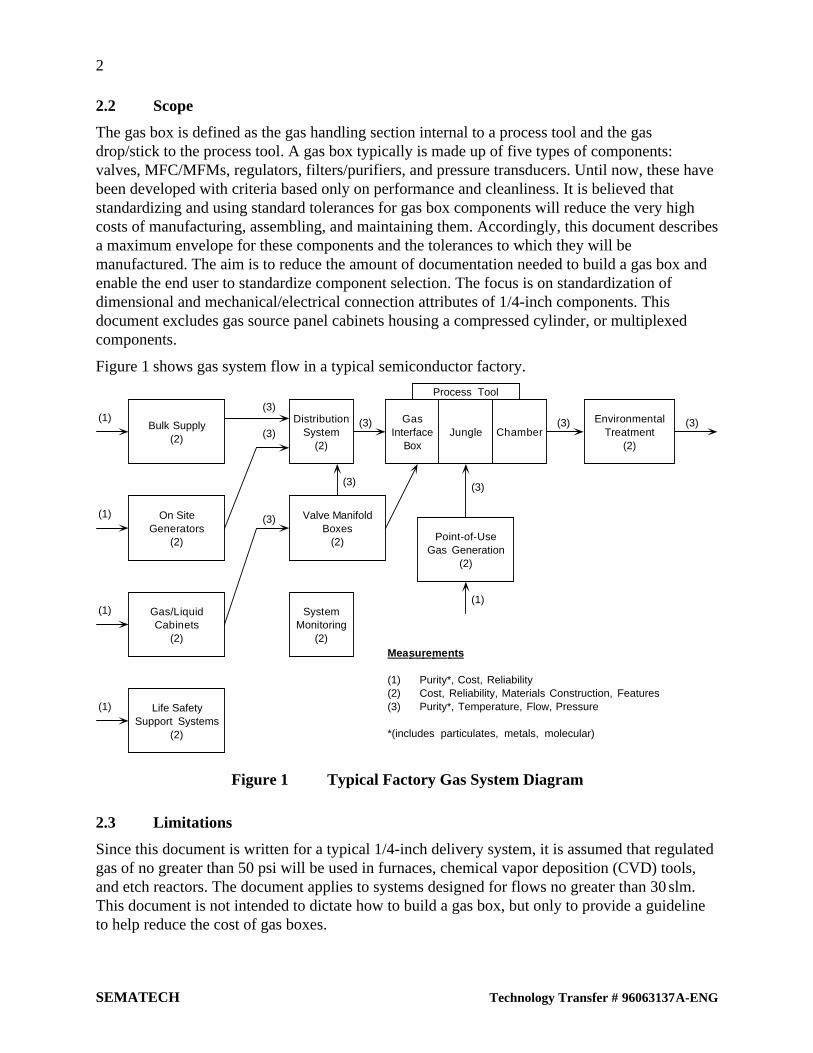
The gas box is defined as the gas handling section internal to a process tool and the gasdrop/stick to the process tool. A gas box typically is made up of five types of components:valves, MFC/MFMs, regulators, filters/purifiers, and pressure transducers. Until now, these havebeen developed with criteria based only on performance and cleanliness. It is believed thatstandardizing and using standard tolerances for gas box components will reduce the very highcosts of manufacturing, assembling, and maintaining them. Accordingly, this document describesa maximum envelope for these components and the tolerances to which they will bemanufactured. The aim is to reduce the amount of documentation needed to build a gas box andenable the end user to standardize component selection. The focus is on standardization ofdimensional and mechanical/electrical connection attributes of 1/4-inch components. Thisdocument excludes gas source panel cabinets housing a compressed cylinder, or multiplexedcomponents.
Figure 1 shows gas system flow in a typical semiconductor factory.
Bulk Supply(2)
DistributionSystem
(2)
SystemMonitoring
(2)
GasInterface
BoxJungle Chamber
EnvironmentalTreatment
(2)
On SiteGenerators
(2)
Gas/LiquidCabinets
(2)
Life SafetySupport Systems
(2)
(1)
(1)
(1)
(1)
(1)
Valve ManifoldBoxes
(2) Point-of-UseGas Generation
(2)
(3)
(3)
(3)
(3)
(3) (3)
(3) (3)
Mea su re me nts
(1) Purity*, Cost, Reliability(2) Cost, Reliability, Materials Construction, Features(3) Purity*, Temperature, Flow, Pressure
*(includes particulates, metals, molecular)
Process Tool
Figure 1 Typical Factory Gas System Diagram
2.3 Limitations
Since this document is written for a typical 1/4-inch delivery system, it is assumed that regulatedgas of no greater than 50 psi will be used in furnaces, chemical vapor deposition (CVD) tools,and etch reactors. The document applies to systems designed for flows no greater than 30 slm.This document is not intended to dictate how to build a gas box, but only to provide a guidelineto help reduce the cost of gas boxes.

3
Technology Transfer # 96063137A-ENG SEMATECH
3 TERMINOLOGY
Definitions of terms used in this document are as follows:
Component n: (1) An individual piece or a complete assembly of individual pieces, includingindustrial products that are manufactured as independent units, capable of being joined with otherpieces or components. The typical components referred to by the specification are valves,fittings, regulators, gauges, instrument sensors, a single length of tubing, several pieces of tubingwelded together, tubing welded to fittings, and the like [SEMI F1-90]. (2) The fundamental partsof an object, its entities, or relationships [SEMATECH]. (3) The hardware and software thatwork in sets (functional entities) to perform the operation(s) [SEMATECH].
Filter n: Of a fluid distribution system filter, the assembly consisting of a filter cartridge andhousing. Examples are an integral unit, in which the filter cartridge and element are not separableand a separable unit, in which the filter cartridge and housing can be disassembled[SEMATECH].
Gas box n: A subsystem of the factory gas delivery system located at point-of-use, typicallyinternal to a semiconductor process tool, and utilized to control delivery of process gases into theprocessing chamber. Also referred to as gas interface box and gas jungle.
Mass flow controller (MFC) n: A self-contained device (consisting of a transducer, control valve,and control and signal-processing electronics) commonly used in the semiconductor industry tomeasure and regulate the mass flow of gas [SEMI E29-93].
Mass flow meter (MFM) n: A self-contained device, consisting of a mass flow transducer andsignal-processing electronics, commonly used in the semiconductor industry to measure the massflow of gas [SEMI E29-93].
Pressure transducer n: A device commonly used in the semiconductor industry to measure gaspressure. Typically consisting of a sensor and signal-processing electronics, this device allowsfor remote indication of gas pressure.
Purifier n: An in-line device used for the removal of homogeneous impurities from gases,typically consisting of a packed-bed of active solids contained in a stainless steel housing. Theactive purification media may remove impurities such as moisture, oxygen, CO, CO2,hydrocarbons, hydrogen, or nitrogen from specific gases using a variety of chemical reaction,physisorption, or chemisorption mechanisms. Point-of-use purifiers often contain a particle filterwithin the same housing.
Regulator n: A valve designed to reduce a high incoming pressure (for example, from a cylinder)to a lower outlet pressure by automatically opening to allow flow until a desired, preset pressureon the outlet side is reached, then automatically throttling closed to stop further pressureincrease[SEMI International Standards 1990, Vol. 1, Glossary].
Valve n : (1) A device that controls the flow or pressure of a gas. Valve functions can includeshutoff, metering, backflow prevention, and pressure relief [SEMI Chemicals/Gases, Vol. 1,1990 (no longer in print)]. (2) Any component designed to provide positive shutoff of fluidmedia with the capability of being externally operated [SEMATECH].
4
SEMATECH Technology Transfer # 96063137A-ENG
4 SUMMARY OF THE GUIDE
The S100 PTAB working group determined that a guideline for each of the five typical types ofgas box components should include the following items:
1. Physical characteristics unique to each component. This would include a generalized drawingof the typical device, specific end-to-end lengths, maximum envelope information,base-to-centerline dimensions, and mounting hole dimensions.
2. Where applicable, electrical connections specific to these components. These would includepin-outs and types of connectors.
3. Tolerances. These would include quantities that the committee accepted as being the best thatcould be achieved without excessive cost penalty.
5 PROCEDURE
Gas box components should comply with the designs provided in the figures of this section.
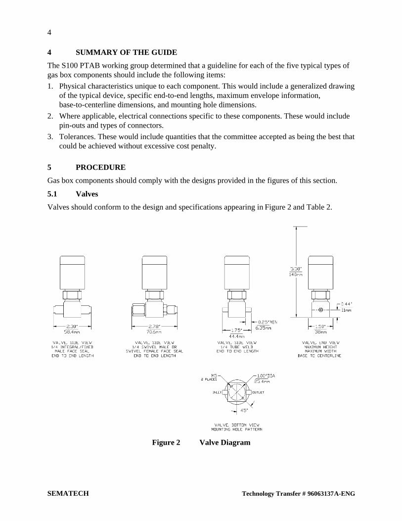
5.1 Valves
Valves should conform to the design and specifications appearing in Figure 2 and Table 2.
Figure 2 Valve Diagram
5
Technology Transfer # 96063137A-ENG SEMATECH
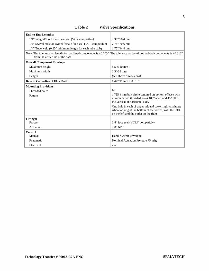
Table 2 Valve Specifications
End-to-End Lengths:
1/4” Integral/fixed male face seal (VCR compatible)
1/4” Swivel male or swivel female face seal (VCR compatible)
1/4” Tube weld (0.25" minimum length for each tube stub)
2.30"/58.4 mm
2.78"/70.6 mm
1.75"/44.4 mm
Note: The tolerance on length for machined components is ±0.005". The tolerance on length for welded components is ±0.010"from the centerline of the base.
Overall Component Envelope:
Maximum height
Maximum width
Length
5.5"/140 mm
1.5"/38 mm
(see above dimensions)
Base to Centerline of Flow Path: 0.44"/11 mm ± 0.010"
Mounting Provisions:
Threaded holes
Pattern
M5
1"/25.4 mm bolt circle centered on bottom of base withminimum two threaded holes 180° apart and 45° off ofthe vertical or horizontal axis.
One hole in each of upper left and lower right quadrantswhen looking at the bottom of the valves, with the inleton the left and the outlet on the right
Fittings:Process
Actuation
1/4" face seal (VCR® compatible)
1/8" NPT
Control:Manual
Pneumatic
Electrical
Handle within envelope.
Nominal Actuation Pressure 75 psig.
n/a
6
SEMATECH Technology Transfer # 96063137A-ENG
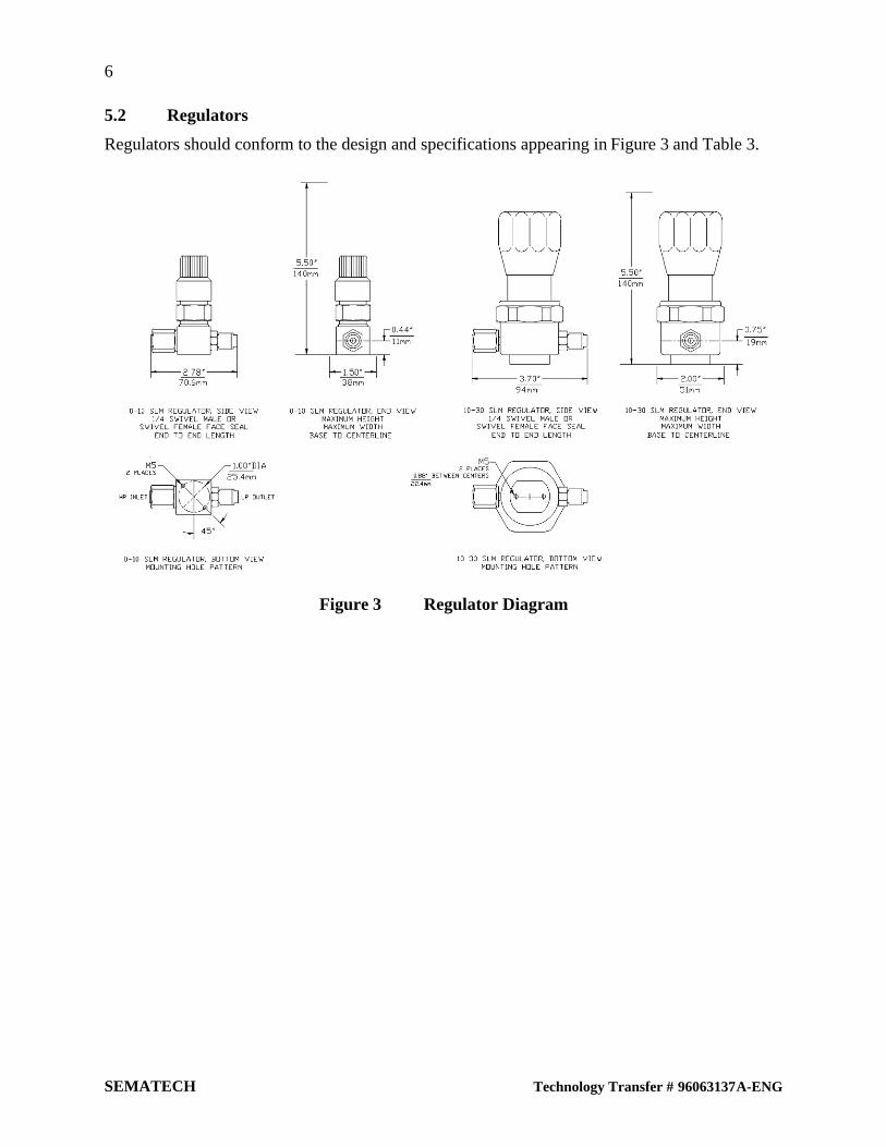
5.2 Regulators
Regulators should conform to the design and specifications appearing in Figure 3 and Table 3.
Figure 3 Regulator Diagram

7
Technology Transfer # 96063137A-ENG SEMATECH
Table 3 Regulator Specifications
0–10 SLM Regulators 10–30 SLM Regulators
End-to-End Lengths:
1/4” integral/fixed male face seal (VCR compatible)
1/4” swivel male or swivel female face seal (VCR compatible)
1/4” tube weld (0.25" minimum length for each tube stub)
—
2.78"/70.6 mm
—
—
3.70"/94 mm
—
Note: The tolerance on length for machined components is ±0.005". The tolerance on length for welded components is ±0.010"from the centerline of the base.
Overall Component Envelope:
Maximum height
Maximum width
Length
5.5"/140 mm
1.5"/38 mm
(see above dimensions)
5.5"/140 mm
2.0"/51 mm
(see above dimensions)
Base to Centerline of Flow Path: 0.44"/11 mm ±0.010" 0.75"/19 mm ±0.010"
Mounting Provisions:
Threaded holes
Pattern
M5
(Same pattern defined abovefor valves in Table 2 andFigure 2)
M5
Two threaded holes, centeredon bottom of base, in line withflow path, spaced 0.88”/22.4 mm between centers
Fittings:
Process
Actuation
¼ face seal (VCR compatible)
n/a
¼ face seal (VCR compatible)
n/a
Control:
Manual
Pneumatic
Electrical
Handle within envelope
n/a
n/a
Handle within envelope
n/a
n/a
8
SEMATECH Technology Transfer # 96063137A-ENG
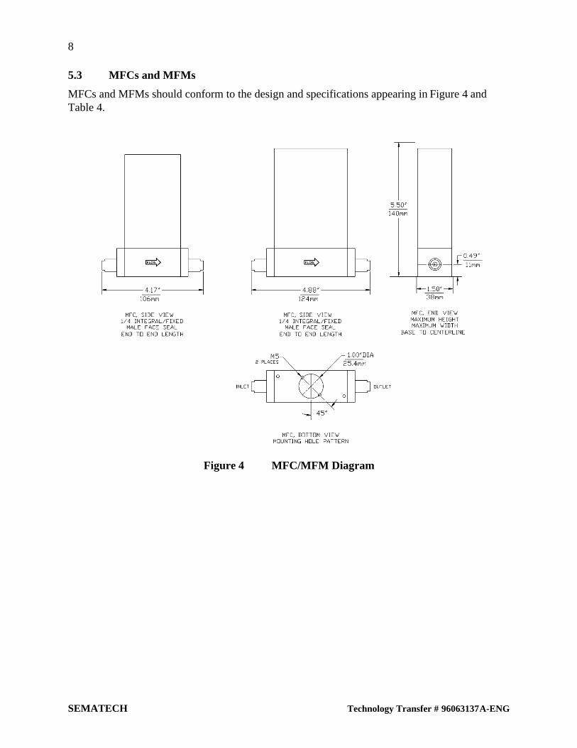
5.3 MFCs and MFMs
MFCs and MFMs should conform to the design and specifications appearing in Figure 4 andTable 4.
Figure 4 MFC/MFM Diagram
9
Technology Transfer # 96063137A-ENG SEMATECH
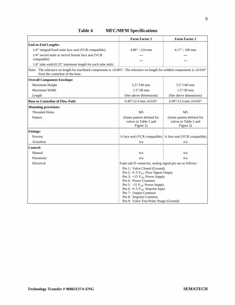
Table 4 MFC/MFM Specifications
Form Factor 1 Form Factor 2
End-to-End Lengths:
1/4” integral/fixed male face seal (VCR compatible)
1/4” swivel male or swivel female face seal (VCRcompatible)
1/4” tube weld (0.25" minimum length for each tube stub)
4.88" / 124 mm
—
—
4.17" / 106 mm
—
—
Note: The tolerance on length for machined components is ±0.005". The tolerance on length for welded components is ±0.010"from the centerline of the base.
Overall Component Envelope:
Maximum Height
Maximum Width
Length
5.5"/140 mm
1.5"/38 mm
(See above dimensions)
5.5"/140 mm
1.5"/38 mm
(See above dimensions)
Base to Centerline of Flow Path: 0.49"/12.4 mm ±0.010" 0.49"/12.4 mm ±0.010"
Mounting provisions:
Threaded Holes
Pattern
M5
(Same pattern defined forvalves in Table 2 and
Figure 2)
M5
(Same pattern defined forvalves in Table 2 and
Figure 2)
Fittings:
Process
Actuation
¼ face seal (VCR compatible)
n/a
¼ face seal (VCR compatible)
n/a
Control:
Manual
Pneumatic
n/a
n/a
n/a
n/a
Electrical 9-pin sub D connector, analog signal pin out as follows:
Pin 1: Valve Closed (Ground)Pin 2: 0–5 VDC Flow Signal OutputPin 3: +15 VDC Power SupplyPin 4: Power CommonPin 5: -15 VDC Power SupplyPin 6: 0–5 VDC Setpoint InputPin 7: Output CommonPin 8: Setpoint CommonPin 9: Valve Test Point /Purge (Ground)

10
SEMATECH Technology Transfer # 96063137A-ENG
5.4 Pressure Transducers
Pressure transducers should conform to the design and specifications appearing in Figure 5 andTable 5.
Figure 5 Pressure Transducer Diagram
Table 5 Pressure Transducer Specifications
End-to-End Lengths:
1/4” integral/fixed male face seal (VCR compatible)
1/4” swivel male or swivel female face seal (VCR compatible)
1/4” tube weld (0.25" minimum length for each tube stub)
2.24"/56.9 mm
3.05"/77.5 mm
1.85"/47.0 mm
Note: The tolerance on length for machined components is ±0.005". The tolerance on length for welded components is±0.010" from the centerline of the base.
Overall Component Envelope:
Maximum height
Maximum width
Length
5.5"/140 mm
1.5"/38 mm
(See above dimensions)
Base to Centerline of Flow Path: 0.50"/12.7 mm ±0.010"
Mounting Provisions:
Threaded holes
Pattern
n/a
n/a
Fittings:
Process
Actuation
¼ face seal (VCR compatible)
n/a
Control:
Manual
Pneumatic
Electrical
n/a
n/a
4-pin Bendix connector, analog signal pin out as follows:Pin A : + 4–20 mA excitation, + power inputPin B : pressure output/signal outputPin C : optional (open if not used)Pin D : - 4–20 mA negative, power and signal/ground
11
Technology Transfer # 96063137A-ENG SEMATECH
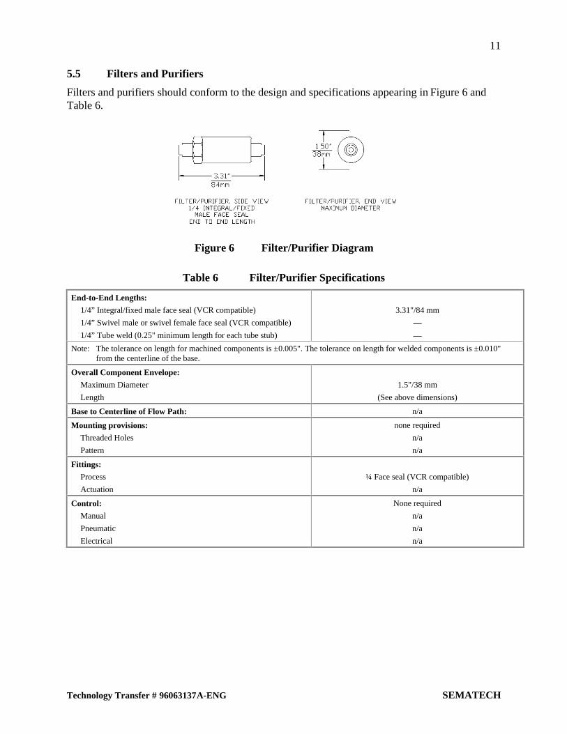
5.5 Filters and Purifiers
Filters and purifiers should conform to the design and specifications appearing in Figure 6 andTable 6.
Figure 6 Filter/Purifier Diagram
Table 6 Filter/Purifier Specifications
End-to-End Lengths:
1/4” Integral/fixed male face seal (VCR compatible)
1/4” Swivel male or swivel female face seal (VCR compatible)
1/4” Tube weld (0.25" minimum length for each tube stub)
3.31"/84 mm
—
—
Note: The tolerance on length for machined components is ±0.005". The tolerance on length for welded components is ±0.010"from the centerline of the base.
Overall Component Envelope:
Maximum Diameter
Length
1.5"/38 mm
(See above dimensions)
Base to Centerline of Flow Path: n/a
Mounting provisions:
Threaded Holes
Pattern
none required
n/a
n/a
Fittings:
Process
Actuation
¼ Face seal (VCR compatible)
n/a
Control:
Manual
Pneumatic
Electrical
None required
n/a
n/a
n/a
12
SEMATECH Technology Transfer # 96063137A-ENG
6 RELATED DOCUMENTS
In pursuit of standard designs for gas box components, the reader may benefit from the followingperviously published SEMATECH documents:
1. SEMASPEC Test Method for Determination of Helium Leak Rate for Gas DistributionSystem Components, Technology Transfer #90120391B-STD
2. SEMASPEC Test Method for Determination of Regulator Performance Characteristics forGas Distribution System Components, Technology Transfer #90120392B-STD
3. SEMASPEC Test Method for Determination of Filter Flow Pressure Drop Curves for GasDistribution System Components, Technology Transfer #90120393B-STD
4. SEMASPEC Test Method for Determination of Valve Flow Coefficients for GasDistribution System Components, Technology Transfer # 90120394B-STD
5. SEMASPEC Test Method for Determination of Cycle Life of Automatic Valves for GasDistribution System Components, Technology Transfer #90120395-STD
6. SEMASPEC Test Method for Determination of Total Hydrocarbon Contribution by GasDistribution System Components, Technology Transfer #90120396B-STD
7. SEMASPEC Test Method for Determination of Moisture Contribution by Gas DistributionSystem Components, Technology Transfer #90120397B-STD
8. SEMASPEC Test Method for Determination of Oxygen Contributionby Gas DistributionSystem Components, Technology Transfer #90120398B-STD
9. SEMASPEC Test Method for Determination of Inonic/Organic Extractables for GasDistribution System Components, Technology Transfer #90120399B-STD
10. SEMASPEC Test Method for Determination of Surface Roughness by Contact Profilometryfor Gas Distribution Systems Components, Technology Transfer #90120400B-STD
11. SEMASPEC Test Method for Scanning Electron Microscope (SEM) Analysis of MetallicSurface Condition for Gas Distribution System Components, Technology Transfer#90120401B-STD
12. SEMASPEC Test Method for Energy Dispersing X-Ray (EDX) Analysis of Metallic SurfaceCondition for Gas Distribution System Components, Technology Transfer#90120402B-STD
13. SEMASPEC Test Method for XPS Analysis of Surface Composition and Chemistry ofElectropolished Stainless Steel Tubing for Gas Distribution System Components,Technology Transfer #90120403A-STD
14. SEMASPEC Test Method for Determination of Surface Roughness by Scanning TunnellingMicroscopy (STM) for Gas Distribution System Components, Technology Transfer#90120404B-STD
15. SEMASPEC Test Method for AES Analysis of Surface and Oxide Composition ofElectropolished Stainless Steel Tubing for Gas Distribution Systems Components,Technology Transfer #90120573B-STD
16. SEMASPEC Guide to Provisional Test Methods for Mass Flow Controllers (MFCs),Technology Transfer #92071220B-STD
13
Technology Transfer # 96063137A-ENG SEMATECH
17. SEMASPEC Provisional Test Method for Determining Accuracy, Linearity, Repeatability,Short Term Reproducibility, Hysterisis and Deadband of Thermal Mass Flow Controllers,Technology Transfer # 92071221B-STD
18. SEMASPEC Provisional Test Method for Determining Reproducibility and Zero Drift forThermal Mass Flow Controllers (MFCs), Technology Transfer #92071222B-STD
19. SEMASPEC Provisional Test Method For Determining Warm-Up Time of Mass FlowControllers (MFCs), Technology Transfer #92071223B-STD
20. SEMASPEC Provisional Test Method For Determining Reliability of a Mass FlowController (MFC), Technology Transfer #92071224B-STD
21. SEMASPEC Provisional Test Method For Verification of Calibration Accuracy andCalculation of Conversion Factors For a Mass Flow Controller Using Surrogate Gases,Technology Transfer #92071225B-STD
22. SEMASPEC Provisional Test Method For Determining Particle Contribution by MassFlow Controllers (MFCs), Technology Transfer #92071226B-STD
23. SEMASPEC Provisional Test Method for Determining Moisture, Oxygen, and TotalHydrocarbon Contribution/Retention by Mass Flow Controllers (MFCs), TechnologyTransfer #92071227B-STD
24. SEMASPEC Provisional Test Method For Determining Mass Flow Controller (MFC)Performance Characteristics from Ambient and Gas Temperature Effects, TechnologyTransfer #92071228B-STD
25. SEMASPEC Provisional Test Method For Determining Pressure Effects on Indicated andActual Flow for Mass Flow Controllers (MFCs), Technology Transfer #92071229B-STD
26. SEMASPEC Provisional Test Method For Determining Steady-State Supply Voltage Effectsfor Mass Flow Controllers (MFCs), Technology Transfer #92071230B-STD
27. SEMASPEC Provisional Test Method for Evaluating the Electromagnetic Susceptibility ofThermal Mass Flow Controllers (MFCs), Technology Transfer #92071231B-STD
28. SEMASPEC Provisional Test Method for Determining Attitude Sensitivity of Mass FlowControllers (Mounting Position), Technology Transfer #92071232B-STD
29. SEMASPEC Provisional Test Method for Determining the Corrosion Resistance of MassFlow Controllers (MFCs), Technology Transfer #92071233B-STD


SEMATECH Technology Transfer2706 Montopolis Drive
Austin, TX 78741
http://www.sematech.org