s. // project report of wood-gas insurface transportationpdf.usaid.gov/pdf_docs/pnaaw071.pdf ·...
TRANSCRIPT

S -
Project Report
Extensive Uses of Wood-Gas In Surface Transportation
TAET
Treeo Center University of Florida
Gainesville Florida
82 5 bull 15
FebruaryJune Session 1982
by Aubrey Marks (Guyana)
~ SSWt
4zUSL22S~_________________________ 4 1~~1gt44~~ ~5 ~ ~ ~ 2$44$~~p~fq~ ~ ~4l4 T4fl 4y34 ~hgtt ~ P 444 jv~tlt V ~
1 ~~ ~ lt -4
p 4 jSV4~4tVAjAV4kLd ir3~~ $4 A 4~tt 1 ~AjflAltiffi il~KK$ti~t1
Thhn iampthe summer of1940 a law ~4as passed o~deringampstamp~to
all driving whatsoever Every gallon4of gasoline inthe coutntry belongedttoP 1 4
~ ~
the government even the fuel in an Individual citizens ~ar Farm~rs 45 4
444 3 couldnt get their milk to market sothey4dumped what they couldnt use 1 lf
themselves it was chaos for a while a rationing planAasP
So in time ~theadopted but0there was nott-enc~ h gasoline obviously1
- - 3
K country began to make the switch to wood gasification I droVe a 1936 Chevy 4 gt43 A
4
~~i3V for a living and had to make minor timing changes t6 the engine ~
- This paragraph was extracted from a report written gtby a citizen In ~274~lt
~rEurope during the Second W6rld War 14 )
411- 44
i4 24 p31
413 1~i
(In
2~344
1
mu ~
A V
t~ ~ I
4141 ~34
I 3)1
4 444 4 1 1
A 144
4(~1 - 44 IA 4 it
14 4
I 4
- ~tN 1 4
- 4~~2t4~~v ~1 34
1-~j 3
~4
3 4 4 ~ 41gt3~4
44 4
~ i4Vgt113 4 3
1
3 I4 34
I4 14 4
A 1 141
~ 14gt~3 ~ 4~ 34~44 444 ~
dir41 3 v v St~ ~f A
a 14 ~4tAI4t3v~14thl p tzCt4k 14 ~ 4 414u4c 4341I 3 3 4 4~p 44 4 A fl 4
14 111~14144441k j 4I I A II43 44 lt~ 4 1 4ltgt 4~NA44
4 43 lt~ p j~ 7~ ~) P3 1 1 1 ~M434t1ty ~ 1 31 ~
14 4 1744
4 4
Acknowledgment
hereby express my sincere gratitude to the US AID especially
Mrs S Samuels of the Guyana Mission the Guyana Government and the staff
at TAET (University of Florida) for their guidance and cooperation
I
Abstract
This project entitled Extensive Uses of Wood-Gas In SurfIransportation describes the utilization of biomass gasificationsurface transportation where all the energy in the gas that leaves gasifier is utilized
A system was developed for the petrol-powered river-crafts and rovehicles to obtain their energy inone of these modes
(a) Wood-gas
(b) Gasoline
(c) A mixture of wood-gas and gasoline The fuel mode is obtained by selecting the position of a multi-positij
electrical switch which provides the requirement instantly In addition to this the river-craft will have the following facilities]
(a) Cooling or heating of a particula space (b) Meal handling facilities
(c) Water distillation facilities All of these auxiliary facilities obtain their energy from the wood-gas
generator without impairing the performance of the engine
Contents
Page
Acknowledgment i Abstract o
1 IntroductionficatioProce 3 2 Gas Production 3
21 The Gasification Process f3
22 Gasifiers 4 3 Gas Refining and Uses 8
31 The Wood-GasGasoline Fuel Supply System 9
32 The Gas Preparation System 15
33 The Space HeatingCoolingFan System 17 34 The Meal Handling System 22
35 The Water Distillation System 24 4 General Observation 25
Y -4 o deg
Introduction
Energy the ability to do work cmes to ouran attention principallAinput for economic development Modern societies depend on the prnAtion and use of large amounts of enerqy tr2 achieve their projectionsGuyana like many other developing countries has had difficultiesthe petroleum fuel price escalation
Unpredictable diminishingwill Petroleumencourage suppliesthe acceptance and increasingof suitable cost]alternative technologiesnation can decrease its reliance fit
available alternative fuels
on petroleum fuels by increasing the useiVand conversion technologies in the transpor
sector i Several reasons have caused this sector to be considered Theseinclude the following
(a) The transport sector has a siqnificant energy need whichcould be jeopardized by increasing fuel prices and unreliable supplies
(b) There is access to an alternative supply of fuel largeenough to meet demandits Eighty percent of Guyana isestimated to be covered by forests(c) It is Possible to obtain the technological expertiseequipment required to convert biomass to a
and
(d) An estimated 95 more usable form
of the energy used in surface transporshytation is obtained from petroleum Buses transport thelargest percentage of public commuters The freight distrishybution system is done mainly by trucks while river-crafts are also employed in both areas
I
People have adopted conventional energy to a wide use of personal and
industrial uses The most significant uses are for cooking heating
cooling illumination tranisportation communication and mechanical work
The utilization of indigenous material to power the surface transport
sector must now be adopted by the-people Wood-gasification can continue to
supply the convenient liquid fuel that we have come to depend on during
the age of low-cost petroleum
Biomass materials can be converted to a number of useful products
which are needed as energy sources They can be converted directly -by
combustion or to an economically transportable fuel by chemical
thermochemical Gr biological processes
Gasification by the thermochemical method is suitable for surface
transportation Two broad approaches to gasification can be distinguished
ie
(a) Gasifiers in which relatively large particles subjectedare
to inherently slow heating rates and long retention times
yielding gaseous products
(b) Gasifiers in which rather finely divided material is heated
rapidly and the products are both gaseous and solid (char)
The gases produced through gasification have a wide range of energy
content and corresponding applications Using gas with an energy content
below 200 BTUSCF may result in some loss of performance in engines or
boilers
Automobiles and river-crafts are primarily transportation devices
Temperature control in the passenger and storage compartments will always
be less important than the primary function of transportation Therefore
the design considerations of these auxiliary systems must not impair the
smooth operation of the vehicles prime-mover
2
2 Gas Production
Solid fuels such as biomass have a limit to direct use in some cirshycumstances while on the other hand gaseous fuels are preferred because they are clean burning and easy to distribute
21 The Gasification Process
Gasification of solid fuels is accomplished in high temperature proshycesses similar to combustion which converts the fuel to a gas
Air-gasification is the simplest method but gives a gas of low energycontent that must be close-coupled to its end-use of heat or mechanical
power
The mechanics of gasification vary widely in different processes but -each particle of biomass must undergo some or all of these stages
(a) Drying
(b) Evolution of hydrocarbons
(c) Combustion of fixed carbons In wood gasifiers these processes proceed continuously in a vessel
under controlled conditions The first stage drying occurs at a tempshyerature of 1000C and locally the temperature cannot rise until all the water has been driven off Due to the low thermal conductivity of biomass and the even lower conductivity of char larger pieces can be burning on the outside while there is still moisture inside
The breakdown of biomass material by heat to yield a medium energy gasoil and char is called pyrolysis Biomass gasification produces hydrocarbon
3
gases which are not ignited in the process Additionally some of the heat
CO2 and CO produced by combustion react as follows
(a) Heat + wet wood - dry-wood + H20
(b) Heat + C02 + C - 2C0
(c) Heat t CO + H O- C02 + H2 The resulting gas which contains CO H2 C02 H20 CH4and other hydroshy
carbons (as aswell N2 when air is used) flows from the gas generator This gas has some sensible heat but most of its energy is carried as latent
chemical energy
Air-gasification of wood can be summarized by the following
(a) Wood-gas contains sensible heat and latnet chemical energy
when it leaves the gas-generator
(b) Inside the gas-generator most of the sensible heat is reconshy
verted to latent energy by evaporating water reducing CO2 and H20 to produce CO and H2 and volatilizing hydroshy
carbons from unburned wood
(c) Products of the different reactions pass out of the gasifier
as a gas with a latent energy of 100 to 900 BTUSCF
d) Inorganic ash will remain after the reaction and must be
removed either continuously or in batches
22 Gasifiers
Gasifiers the reaction units are in a seemingly bewildering variety
The principal types are as follows
4
221 Air Gasification
(a) Updraft
(b) Downdraft
(c) Fluidized bed
(d) Suspended bed
222 Oxygen gasification
223 Hydroqen Gasification
224 Pyrolysis Gasification
225 Electrochemical Gasification
Other aspects are also considered when wood-gasifiers are beinc examined These are
(a) Fuel type and form chips pellets powder etc (b) Ash type dry ash or slag
(c) Pressure suction low-pressure or high-pressure The simplest way to produce gas is by air-gasification where air is
used to oxidize the biomass and generate heat for the reactions This
5
process has the most immediate use with mobile or stationary engines and
those built for engine operation generally operate under a slightly negashy
tive pressure due to the intake stroke of the engine
Updraft Gasifier
The simplest air-gasifier is the updraft (counterflow) type where air
is introduced to the biomass through the bottom of the furnace Rather high
temperatures are generated initially where the air first contacts the char
The combustion gases immediately enters a zone of excess wood and char
where C02 or H20 is reduced to CO and H2 from the excess carbon
As the gases rise to lower temperature zones Fig 1 they meet the
descending biomass and pyrolyze the mass at temperatures of 200degC to 500degC
Continuing to rise the gas contacts wet incoming biomass and dries it The
counter-flow of gas and biomass exchanges heat so that the gas exits at a
lower temperature
This type of gasifier has several disadvantages A wide variety of
chemicals tars and oils are produced in the pyrolysis zone and if allowed
will cindense in cooler regions For this reason the gas is usually used
in close-coupled modes in which the tars and oils will burn and contribute
to the final energy content of the gas
Downdraft Gasifier
The downdraft gasifier (co-flow) shown in Fig 2 eliminates the tars
and oils in the gas as produced in the updraft type
Air is introduced through a set of nozzles and the products of combusshy
tion are drawn downward through a bed of hot charcoal extending towards the
grate This causes the oils and vapours in the higher regions to be cracked
ryingbull
PyrolysI s
Air _ Reduction
D
- o
-Grate
Fig 1 Updraft Gasifier
Drying 0
PyrolysisAir Oxidation
Grate -Reduction _ - GasGas
Fig 2 Downdraft Gasifier
7
into gases
The tars and oils are reduced to less than 10 of the value produced in
updraft gasifiers making the gas suitable for supplying energy to
prime-movers or as heat sources
Gasifier Parameters
The optimum operation of a gasifier depends on the construction and
the physical and chemical characterisLics of the fuel used These include
(a) Provision for the condensation and removal of excess
moisture
(b) Proper shaping and sizing of the fuel stock to prevent
bridging
(c) Proper dimensioning of the combustion and reduction zones to
produce high quality gas If the combustion zones diameter
is toG small the gas production will be limited If it is
too large the tar content of the gas will be increased
(d) Ash removal systems must be facilitated but the loss of char
should be minimized
3 Gas Refining and Uses
Gas produced from air-gasification of wood in the downdraft gasifier
consists of the following components
(a) Carbon monoxide
(b) Hydrogen (gas)
c) Carbon dioxide
N I
F
A1
(d) Methane
(e) Nitrogen
(f) Water
~()Ash
(h) Soot~~~~~~~~~~~~~~~ o fthese e noncomponents mb Ustible and t heir reare i m natioonco required for producing the highest possible BTU valueunit volume Large concentrations of solids in the gas will cause operational and accelerate engine wear These undesirables such as solids moist
and heat willbe removed by the following systemsallow the Removal ofgas to have a higher latent the
heating valueunit volume
utilized for useful purposesAdditionally it is conveniently arranged for the driver to be able
change from gasoline to wood-gas aor mixture of the two fuels boperation ofa simple~selector switch
Fig 3 shows the entire utilization of the sensible and latent heat values of the gasifiers output
31 The Wood-GasGasoline Fuel System
he design of this fuel system aims at allowing the operator of petrol engine to be able to use wood-gas gasoline or a mixture of fuels as required The electriaIcotosare elcticll operated n ifand two dfi
ent electrical circuits with different types of components are madecontrol four solenoids
Fig 4 shows the layout of the modified fuel system with thecfo
4~~4 ~9
GasolineMobile Wood-Gas Utilization System
Distillation Unit
Hot Water
ltHeatingCooling Unit
Flare H
Cooling Fan
Gasoline
Line oEngine
Air
Gasifier
Cyclone Oil-Pump Oil Bath Gas Burner
Filter
Fig 3
~Tamp ~i_ _ _ solenoid t a are either-fully opened-or-c-losedshy
of gasoline the carburetorSolenoidB controls the flow of air to the carburetorlt Solenoid C controls the flow of air to t he wood-gas mixing bo
viSolenoid D controls the fl1ow of wood-gas to the mixing box~ -
Figs 5 and 6 are the two different electrical circuits that
the operation of the solenoids Fig 5 a multi-contact switch is utilized if the sel
Positioned to wood-gasuse current will flow through contacts 1 anthereby energizing solenoids C and 0 and allowing air and wood-gasgtt into the engine Both quantities are regulated by butterfly valves co ted to the throttle
When gasolineis Selected contacts 3 and 4 are closed)noids A and B to be energized This allows gasoline and air to flowtOw the carburetor and into the enginej
A mixture of the fuels is accomplished firstly by placing the SOC the correct position This causes contacts 5 6 and7 8 to -be o
resulting in all four solenoids being energized and a mixture-eof t-flowing into the engine
The alternative electrical circuit for the fuel selection con Fig 6 consists mainly of three relays and a simple three-positi sel C
S switch
When the selector is Positioned to wood-gas Relay 3 is enerie current flows to solenoids Cand D Under this conditiono
LLffisss are allowed to flow into the engine
With the selector on gasoline Relay 2 isenergized ca0 causng ole
Wood-GasGasoline Fuel System
Carburetor BGasoline
Wood Gas
SEngine C
- 0 Manifold
C~I
Air --
Foot Pedal
Note A B C and D are normally closed Fig 4 solenoids
L
F I olenidCFuel To Solenoid D To FilterCooler
Relay
Switch Handle
-Sel ectorSwitch
Battery
SwthPsto LSD Contacts
Wood-Gas12345678Enriesoeod Gasoli ne XxA
Gasoline
B C D) ln
Aamp CampD
Fig5 Fuel Electrical System
A B C D
(o- slenoids
Wood-Gas
Swi tch Selector Gasoline
Wood-Gas amp Gasoline
II
Relay Relay Relay 1 2 3
I Battery
FiL 6 Fuel Electrical System
A adBtobe operativecarbuetor ir ad qaso Iine ar
now allowed_ togt~ If am tur of wood-gas and gasoline is SeI~~energized ctd e4 This causes current to flo w epr C it ng ayot
w itoheoperaing Reilaand Relay 3 makin~ h4air qtem energized
are allowed tofo note
-
32 1 2TheGasPreParationSyse
Gas produced in the wodgseeaoIShtn4ties
Accomplishing ot ite-reoa Ofte1Nurtheov re i pu ites and lowerin gerature of the gas will make
Fig 3 shows the comnecomle enee ra ilization anc--utilzaion systejtehtgas fosit aninsulated cyclone wherecoils that are connected to there are tahot water tank This high eprf
I suse frIhetin oI 4
ooingofa p~articular sae Ses c16 4 LC01ing system)
The salrset of coils n~itu smlle(See Water-Distillation
444
colssupply watersteamSystem)4 to the water diSt
In tecyclone heat isabsorbed by the water coilsof the gas separated an oldpaThe gas then flows4 intQ theK ~~~some andbxwhrsolidof its sensible heat to the contents Oihofth o-oFialy hot-boxthe we4be gas passthroughain allyaa fuel sorce itrcF le l-thUntbei u aedsou ce Fg w ui electrical control diagram
7 shows the gas preparation systemf this System is olgas control solenoid _(D)
p rt o a h nt e
4
i nr~e isenergzedprtnh
onloperati olo ~e-onalwhe rte
4 44 4 4
L4 4 444 W 4l4
M14
jlH Cooling Fan
Gas shy - - [-
Inle- Gas Outlet
Filter
Oil Pump
~To Oil PumpTo Solenoid D To Cooling Fan ToOlPm (wood-gas)
Hand Switch
76 5 43 1_
Fuel Selector L Switch _j Relay
Relay
lt- Battery
Fig7 Oil-BathCooierElcticamlSystem
conce oslni
~~~~h andat a-1 rateas
ne e D~2 d -aco
~uI~ii~ oid tatods ole cte d an ope ate whe eve
singile -pole swiche ontrol oft heswputc aren whi
ac mpe r fa Placed in thechca onlycio cue ate wo naltho wo gAn
isliezindut I thse wo wit hes aroil-PUMP and e left i n the O o ifan will operate-2~auomaically ason-gsy the wood g s e
~aa 4 33 TheSpaceHeatingCo l g~
Surtefhaine trnprtto th hetngo
unit are Of majorimotnenaycoig toOf a definite scpe ad scomfortimpotanccontrol serviceis accomplished by Utilizingth anyddsseib
hi s temper gas while not ea ofheimpairing the Power of the engieThe space utilized in a vehicle or Mriver-craftcontrol by theand refrigeration air tempensystems removes this amount of v6 le rprdcinof revenue Therefore specially shapedmust be used cog
T19Fig 8 shows the basic absorption cooling system that wilTheworing fluid isa
ea solution of refrigerant and anaboenwK
~~~from rethe wood-gas isadded to th oltinnth geraothe refrigerant is-~vaporized an Asarixueofwa
~a The heat is then removed fromlisu thliufied inthe condenser Th e teheujnvapor wihIeoiavailabrgere expansion from the high pressure posi t o Ithenavibl 1 of t e s s e to t Il~ 2 s
evprtrti Oint vaporization of the refrigerantocur
a~~ 7
Condenser
Expansion Valve
Hot f EvaporatorWater
co
Generator
Pump Absorber
Fig 8 Absorption Cooling System
00
~r
(D~
0
C0 -f
I
0 -D
0i
0
0A
99
0
Switch Position
Closed Contacts
Solenoid Condition
Motor Condition
EnergizedSolenoids
1 2 3 4 5 6 Open Closed Pump Fan A B
Heat X X X A B run run X
Off
Cool XX X B A run run X
Fan X off run
Ref X run off
Heat-Cool-Fan-Refrigeration Electrical System
20
cooling is achieved The vaporized refrigerant is then recombined in the absorber to form the mixture from which it was initially obtained
Applying this method of cooling at varying loads will be no problem generally because control is easily accomplished by a control of the hot
water flow
For passenger vehicles the cooling load is made up of the following
(a) Passenger body heat
(b) Ventillation and infiltration
(c) Heat transmission through insulation if any
(d) Heat generated from machinery
Systems required for naval use ie on the river-crafts should have more interest in cold-storage facilities This is considered to be more like the large domestic refrigerator to be used by the crew and not an all-refrigerated container ship Perishable foods go aboard fresh smoked salted and frozen For some of these refrigeration is an absolute
necessity
Space is costly aboard ships and many compartments at different tempshyerature cannot be provided practically Some factors that will influence
the design of the system are
(a) It must function under conditions of roll and pitch
(b) Construction materials should be anti-corrosive
(c) It must function under high impact shock conditions and
vibration
(d) It must allow speedy handling of the perishables with minimum
exposure to the atmosphere The electrical diagram which controls the coolingheating system Fig 9
consists mainly of a multi-contact switch and two solenoids When fan is
21
selected contact 5 will be closed and the fan alone will operate without
the effect of hot water
When the selector is placed in the heat position contacts 1 3 and 4
are closed This causes the hot water pump solenoid A and the fan to be
energized causing hot air to be blown into the particular space Solenoids
A and B are normally in their closed positions
Placing the switch in the cool position causes contact 2 to be
closed and energizes solenoid B At the same time contacts 3 and 4 are
closed to allow the hot water pump and fan to be run The hot water now
flows into the generator of an absorption chiller and back to the source
In order for the refrigeration system alone to be working the hot
water pump alone is necessary When placed at Ref the refrigeration
system will operate It can be seen that at position Heat Cool and
Ref the hot water pump is operative and under this condition the
evaporator of the refrigerator is supplied with refrigerant by two hand
operated valves
34 The Meal-Handling System
The provision of a meal handling system was done specifically for the
large river boats These vessels ply the rivers for long hours while accomshy
plishing their task of surface transportation
This facility consists of an ordinary gas burner which uses some of
the refined gas produced by the wood-gas generator (Fig 3) and a hot-box
The hot-box is an ordinary cylindrical container that is installed between
the cyclone and the filtercooler unit Using the hot-box Fiq 10 will
22
Wood-Gas Outlet
THot Wood-Gas Inlet
Sot-Bo
23
facilitate the presence of warm meals when the gasifier is in use The
inner chamber is air sealed and the heat of the hot gas is transferred to
the food containers by radiation and conduction
Presently meals are pre-cooked and taken to the vessels or are preshy
pared on the vessel by using LPG or electrical cookers that are connected to
the vessels generator
35 The Water Distillation System
Distilled water is a commodity that is always in demand and it can be
produced in this system at no cost while cooling the gas at the same time
River boats do encounter rough weather but this facility can be
utilized in semi-rough weather or while being moored with the gasifier in
operation Hot water from the hot water tank Fig 3 is passed through a
super-heater coil and is allowed to flow into a broad bodied container
that is covered by a plastic V-shaped roof
The hot watersteam mixture in the wide-bodied container will allow
evaporation and the condensate will run off the sloping sides nto the
collector
24
SGeneral Observation
The establishment of a system which reducespetroleum fuels or eliminates the use ofin the surface transport sector must be considered as onethat cannot be overemphasized in its importanceAs this system shows it incorporates
immediately leaves the gasifier many uses of the Wood-gas thatAlso there isno objectionablevibration produced by the gasifier and the other systems that depend on it
noise or
The complete unit can be used on distillation
the river boats but cooking and watercan be eliminated when the system is used onRiver boats land vehiclesin Guyana operate for many hours during the day and most of them do not have heating or cooling facilities or if they do the orishyginal source of energy ispetroleum Mealsto the vessel are either pre-cooked and takenor are prepared on the vesselcookers that
by using LPG or electricalare connected to the vessels generatorthe meal Thisto be prepared system allowson the vessel and also keeps it warm while thegasifier is being operatedThe water distillation unit can only be used when the river is relashy
tively calmn or while the vessel ismoored This ensures adistilled water for the batteries and a regular supply of
Possibility of earning revenue
the available
The components of the system must be built to meet the configurationspace Equipment weight is more of
ais towards problem because the trenda lighter vehicle which reducesacceleration the Power required forCorrision fasterresistant material or coatingswhere Possible because must be appliedthe equipmenttions will be subjected to weather condi-Also provision must be designed into the equipment to allow easyand quick maintenance
25
Wood-gas systems are units to be proud of and in reality there is a
slight reduction in the power of the engine But this is compensated for
when considering the cost and availability of wood or any other suitable
biomass material
26
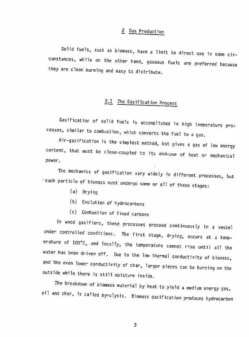
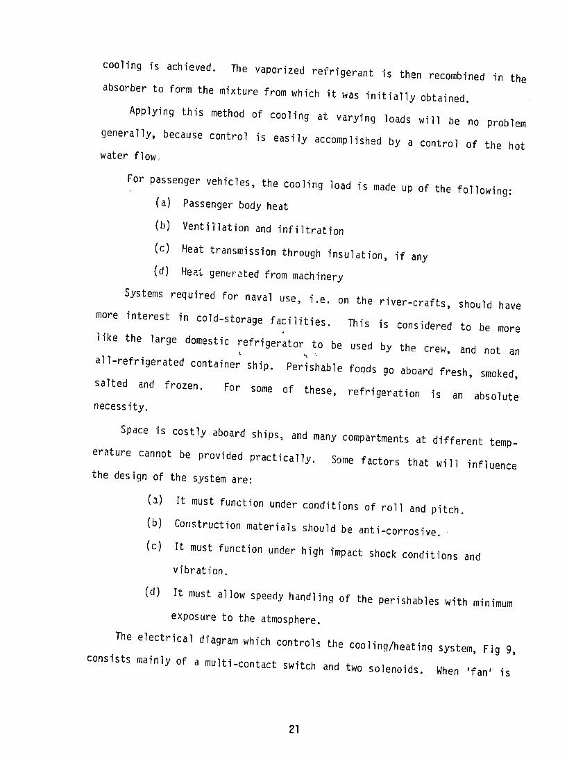

Wood-gas systems are units to be proud of and in reality there is a
slight reduction in the power of the engine But this is compensated for
when considering the cost and availability of wood or any other suitable
biomass material
26