rrfm 2005 transactions - european nuclear society
TRANSCRIPT

TRANSACTIONS
9th International Topical Meeting on Research Reactor Fuel Management 10-13 April 2005, Budapest, Hungary Organised by the European Nuclear Society
http://www.rrfm2005.org
ENS / European Nuclear Society Rue de la Loi 57 1040 Brussels Belgium Phone: +32 2 505 30 50 Fax: +32 2 502 39 02 E-mail : [email protected] Internet: www.euronuclear.org The ENS Topical Meeting on Research Reactor Fuel Management (RRFM) is an annual international conference for professionals in the field of research reactors. Successfully launched in 1997, the meeting has since then grown into a well-established, international forum for the exchange of information and expertise on all significant aspects of the nuclear fuel cycle of research reactors. RRFM focuses on key areas of development and current concern. RRFM 2005 is held at the Hilton WestEnd Hotel in Budapest, Hungary. The content of papers, published in this book, reflect solely the opinions of the authors concerned. The European Nuclear Society is not responsible for details published and the technical accuracy of data presented. These transactions contain all contributions submitted by March 28th, 2005. The RRFM 2005 transactions, in addition to papers received after March 28th, are available on http://www.rrfm2005.org.
TABLE OF CONTENTS
Oral session 1 – International topics - Status report of the utilisation of research reactors in the new and candidate
members of the European Union I. Vidovszky, KFKI Atomic Energy Research Institute, Hungary
1
- The International Project on Innovative Nuclear Reactors and Fuel Cycles (INPRO): General description and implications for the research reactor infrastructure needed for R&D Y. Sokolov, IAEA, Austria
6
- Status, Progress and Plans for the U.S. Department of Energy National Nuclear Security AdministrationGlobal Threat Reduction Initiative Andrew Bieniawski, US DOE, USA
14
- The European Fusion Programme and the role of research reactors R. Lässer, R. Andreani, E. Diegele, EFDA Close Support Unit, Germany
18
- Production of Mo99 in Europe: Status and perspectives H. Bonet, B. David, IRE, Belgium - B. Ponsard, SCK-CEN, Belgium
24
- Irradiation of fuels and materials in the Jules Horowitz reactor: The 6th European Union JHR Co-ordination action (JHR-CA) D. Iracane, D. Parrat , CEA Cadarache, France
28
- Status report on the cost and availability of enriched uranium for research reactors H. Müller, J. Laucht, RWE Nukem, Germany
46
- Why a fast-flux reactor? The Phénix experimental program J. Guidez, L. Martin, J.Dumesmil, CEA Phénix, France
51
- A business operations and decommissioning strategy for the Imperial College London research reactor – A financial risk management approach S. Franklin, Imperial College London, U - D. Gardner, J. Mumford, R. Lea, J. Knight, PURE Risk Management, UK
59
Oral session 2 – Fuel development, qualification, fabrication and licensing - High density U-Mo fuels – Latest results and reoriented qualification
programs J. Snelgrove, ANL, USA - P. Lemoine, CEA Saclay, France – L. Alvarez, CNEA, Argentina
64
- The French U-Mo group contribution to new LEU fuel development J.-M. Hamy, AREVA / Framatome-anp, France - P. Lemoine, CEA Saclay, France – F. Huet, CEA Cadarache, France – C. Jarousse, AREVA / CERCA, France – J.L. Emin, AREVA / COGEMA Logistics, France
73
- Main results and status of the development of LEU fuel for Russian research reactors
80
A. Vatulin, A. Morozov, V. Suprun, I. Dobrikova, VNIINM, Russia
- Main results and status of the CNEA qualification programme for the fabrication of high density MTR fuel L. Alvarez, N. Boero, J. Fabro, CNEA, Argentina
87
- Post-irradiation examinations on U-Mo full-sized plate: IRIS-2 experiment F. Huet, J. Noirot, V. Marelle, S. Dubois, CEA Cadarache, France – P. Boulcourt, P. Sacristan, S. Naury, P.Llemoine, CEA Saclay, France
92
- Mechanical calculations on U-Mo dispersion fuel plates with MAIA V. Marelle, F. Huet, CEA Cadarache, France – P. Lemoine, CEA Saclay, France
98
- Out of pile French research programme on the U-Mo / A1 system : First results S. Dubois, F. Mazaudier, J.P. Piron, P. Martin, J.C. Dumas, F. Huet, CEA Cadarache, France - H. Noël, O. Tougait, University of Rennes, France - C. Jarousse, AREVA / CERCA, France - P. Lemoine, CEA Saclay, France
104
- Qualification of high-density aluminide fuels for BR-2 reactor A. Beeckmans de West Meerbeeck, P. Gubel, B. Ponsard, SCK-CEN, Belgium - T. Pin, J.-.L Falgoux, AREVA / CERCA, France
111
Oral Session 3 – Reactor operation, fuel safety, core conversion - Status report on the nuclear start-up of FRM-II
K. Schreckenbach, H. Gerstenberg, Munich Technical University, Germany
118
- Reduced enrichment programme for FRM-II. Status 2004/05 A. Röhrmoser, W. Petry, N. Wieschalla, Munich Technical University, Germany
123
- Evaluation of research reactor fuel reliability in support of R&D regulatory requirements E. Sokolov, AECL, Canada
130
- Review of the accident source terms for aluminide fuel: Application to the BR2 reactor F. Joppen, SCK-CEN, Belgium
136
- Results of out-of-pile tests of the MIR reactor irradiated fuel at high temperatures A. Izhutov, V. Alexandrov, A. Grachev, Y. Kosvintsev, A. Novoselov, Z. Chechetkina, RIAR, Russia
141
- Analysis of power peaking in HEU and LEU fuel elements on the safety behavior of FRJ-2 R. Nabbi, G. Damm, I. Neuhaus, Research Center Jülich, Germany
147
- HEU to LEU conversion experience at the UMass-Lowell research reactor J. White, L. Bobek, University of Massachusetts Lowell, USA
153

Oral session 4 – Spent fuel management, back-end options, transportation - The United States Foreign Research Reactor Spent Nuclear Fuel Program:
Proposal to modify the program C. Messick, US DOE, USA
159
- R&D for the final disposal of irradiated research reactor fuel elements H. Curtius, H. Brücher, Research Center Jülich, Germany
164
- Reprocessing U-Mo spent fuels: Dissolution experiments on non-irradiated and irradiated materials N. Herlet, G. Ferlay, J.P. Dancousse, A. Juvenelle, CEA VALHRO, France
169
- HABOG: One building for high level waste and spent fuel in The Netherlands. The first year of experience J. Kastelein, H. Codée, COVRA, The Netherlands
174
- Spent fuel from the Finnish TRIGA research reactor in the surroundings of BWR spent fuel final disposal repository. Safety assessment and comparison to the risks of BWR fuel S. Salmenhaara, H. Nordman, M. Anttila, VTT, Finland
181
- Update on NAC's transportation projects C. Anne, J. Patterson, NAC International, USA
186
Poster session 2 – Fuel development, qualification, fabrication and licensing - The analysis of effect of gaseous fission products on serviceability of various
types of fuel elements used in research reactors A. Vatulin, G. Kulakov, A. Kosaurov, A. Morozov, I. Dobrikova, VNIINM, Russia
191
- An investigation on overcoming the interaction problem of U-Mo dispersion fuel by designing simpler monolithic U-Mo rod type fuels and adding third alloying elements to U-Mo Y-S Lee, C-K Kim, K-H Kim, J-M Park, D-B Lee, S-J Oh, H-J Ryu, D-S Sohn, KAERI, Korea
197
- Interdiffusion between U-Mo alloys and Al or Al alloys at 340°. Irradiation plan A. Fortis, M. Mirandou, M. Ortiz, S. Balart, A. Denis, A. Moglioni, P. Cabot, CNEA, Argentina
203
- Irradiation and post-irradiation examination facilities in Argentina for testing of high density U compound plates G. Ruggirello, S. Halpert, G. Estryk, J. Quintana, CNEA, Argentina
207
- Computational and experimental analysis of causes for local deformation of research reactor U-Mo fuel pin claddings in case of high burnups V. Popov, M. Khmelevsky, IPPE, Russia, Russia - V. Lukichev, RDIPE, Russia - O. Golosov, Institute of Reactor Materials, Russia
211

Poster session 3 – Reactor operation, fuel safety, core conversion, spent fuel - Evaluation of 3-D energy distribution in a PWC / CCD device combining
thermal balance methods with MCNP & Origen-S calculation model S. Kalcheva, P. Gouat, SCK-CEN, Belgium
215
- The Valmont program: Improved experimental techniques to support the neutronics qualification of U-MoA1 J.-P. Hudelot, Ch. Döderlein, M. Antony, J. M. Girard, V. Laval, Ph. Fougeras, G. Willermoz, P. Leconte, CEA Cadarache, France
222
- Core conversion study from silicide to molybdenum fuel in the Indonesian 30 MW multipurpose reactor GA Siwabessy (RSG-GAS) T.M. Sembiring, I. Kunturo, BATAN, Indonesia
229
- Progress of activities with regard to reconstruction of the research reactor IRT-Sofia T. Apostolov, E. Anastasova, D. Drenski, V. Anastasov, A. Stoyanova, E. Moskov, S. Belousov, S. Kadalev, INRNE, Bulgaria – L. Manev, M. Baltiyski, AtomEnergoproekt, Bulgaria
234
- WWR-M fuel elements as objects of permanent study and upgrading G. Kirsanov, K. Konoplev, A. Zacharov, A. Poltavski, Petersburg Nuclear Physics Institute, Russia
239
- The CERCA fuel elements instrumentation manufacturing G. Harbonnier, C. Jarousse, T. Pin, M. Febvre, P. Colomb, AREVA / CERCA, France
243
- Burn-up measurements of LEU fuel for short cooling times C. Pereda, C. Henriquez, J. Klein, J. Medel, J. Klein, CCEN, Chile
244
- ETRR-2 in-core fuel management strategy M. Khalil, Alexandria University, Egypt - E. Amin, M. Belal, Atomic Energy Authority, Egypt
249
Poster session 4 – Spent fuel management, back-end options, transportation - Status of the VIND programme. September 2004
M. Pesic, VINCA Institute of Nuclear Sciences, Serbia & Montenegro
255
- New cask for transportation of irradiated rods D. Ohayon, P. Naigeon, AREVA / COGEMA Logistics, France
261
- Strontium and barium precipitation as carbonates in molten eutectic LiC-KCI C. Caravaca, G. Córdoba, M.J. Tomás, CIEMAT, Spain
262
- IR-100 reactor and proposals for spent nuclear fuel management S. Bulkin, V. Tikhonov, V. Parabin, RDIPE, Russia - S. Smirnov, V. Podtynnykh, SNINE, Ukraine
268

1
STATUS REPORT OF THE UTILIZATION OF RESEARCH REACTORS IN THE NEW AND CANDIDATE
MEMBER STATES OF THE EU
ISTVÁN VIDOVSZKY KFKI Atomic Energy Research Institute
H-1525 Budapest, POB 4, Hungary
ABSTRACT The nuclear profile of Europe changed in 2004, when the Central and Eastern European countries joined the EU. New types of NPPs and research reactors appeared. These reactor types are not unknown for the nuclear community, as e.g. papers describing them were presented on previous RRFM meetings. Even some of the related nuclear programs have been presented, however an overview of these research reactors as well as of the programs related to these reactors could be of interest. Four of the ten new member states (Czech Republic, Hungary, Poland, Slovenia) operate research reactors, further two (Latvia and Slovakia) operated research reactors in the past. Two candidate member states (Bulgaria and Romania) operate research reactors as well. The paper describes the programs of research reactor utilization in the mentioned countries and tries to give insight into the future perspectives as well.
Introduction Four of the ten new member states and two candidate member states operate research reactors. The paper describes the research reactors in these six countries and the research and application programs related to them. One has not to forget about the countries, where research reactors have never been operated. Lithuania is one of them, and one can mention, that more than 70% of its electricity is produced by NPPs. However for the audience of RRFM the countries, where research reactors are in operation are of main interest, so further I will concentrate on them. Bulgaria The Institute of Nuclear Research and Nuclear Energy (INRNE) operated the only research reactor of the country. INRNE belongs to the Bulgarian Academy of Sciences. The IRT-2000 reactor was first put into operation in 1961. The power of the reactor was 0.5 MW that time, it was upgraded to 1 MW in 1965 and to 2 MW in 1970. The reactor was designed in the former Soviet Union, who supplied the fuel as well. During the period 1982 – 86 there was a project, supported by the Kurchatov Institute (Moscow) to upgrade the reactor to 5 MW. The project was terminated at the time of the Chernobil accident. Later the future of the reactor was uncertain. In 2001 the government of Bulgaria has taken a resolution for the refurbishment of the reactor into a low power reactor up to 200 kW. The reconstruction project is performed with international cooperation (Kurchatov Institute, Skoda, SCK CEN, etc). The reactor is currently in extended shut-down. The scope of the reconstruction is: - new seismic/safe adjacent building for reactor operations, - modification of existing reactor hall, - addition of a new reactor vessel and replacement of reactor internals, - new primary cooling system and reconstruction of secondary cooling system - new reactor protection system and I&C system, - new radiation monitoring system, - new electrical distribution system including two diesel generators.

2
The proposed new utilization of the reconstructed reactor is: education (students in nuclear engineering, physics, biology, radiation protection), training of NPP operators, neutron activation analysis, production of radioactive isotopes, boron neutron capture therapy (BNCT), testing of instruments and calibrating standards. Czech Republic There are three research reactors in the Czech Republic. Additionally in ŠKODA Works, at Plzeň there was a test reactor, which is already dismounted. The LVR-15 in Řež near Prague is the most significant research reactor of the country. LVR-15 is operated by the Nuclear Research Institute (NRI). NRI is partly owned by ŠKODA. LVR-15 was first put into operation in 1957. The power of the reactor was 2 MW that time; it was upgraded to 4 MW in 1964. The fuel is supplied from Soviet Union, later Russia. The first fuel (1959 – 1974) of LVR-15 was the 10% enriched EK-10. In 1974 during a reconstruction the fuel was changed for 80% enriched IRT-2M. This time the primary heat exchangers were replaced by two 9 MW units. The last reconstruction started in 1988 and was finished in 1991. During this reconstruction all structures and components were replaced except the heat exchangers. The designed thermal power of the reactor is 15 MW, but the licensed power level is 10 MW. In 1995 – 98 the reactor was converted to 36% enrichment, the type of fuel assemblies remained IRT-2M. The reconstructed reactor was designed for 30 years, so the operation is foreseen up to 2018. The reactor is used for: - material testing experiments of reactor pressure vessels at water loops and in irradiation rigs, - activation analysis using a pneumatic rabbit system, - experiments at beam ports in the field of basic and applied physics, - irradiation for medical and radio-pharmaceutical purposes, - irradiation of silicon monocrystals, - BNCT at the former thermal column. The LR-0 low power reactor is also operated by NRI in Řež. LR-0 serves reactor physics and related nuclear fields. It was critical for the first time in December 1982, regular operation started in 1983. The fuel of LR-0 is LEU, the shortened variant of VVER type NPP fuel, with the only difference in length of the fuel rods. The maximum allowed power is 5 kW, but the reactor is usually operated on much lower level. The core can be changed in a very flexible way, so different core configurations can be investigated. At the Czech Technical University in Prague, at the Faculty of Nuclear Sciences and Physical Engineering (FNSPE), a 1 kW reactor, the VR-1, also called VRABEC (Sparrow) is in operation. The reactor was first critical on December 3, 1990. The reactor was designed by Chemoprojekt Praha, based on calculations and analyses performed at FNSPE in cooperation with ŠKODA Plzeň. The major components of the reactor were manufactured by ŠKODA Plzeň. The reactor has been in permanent operation since January 1992. The fuel used is IRT-3M, enrichment 36%, production of Russia. The 1 kW reactor can be operated at 5 kW level for short periods. The reactor is used in the following areas: in the education of technical university students, in scientific research, in respecting reactor parameters and requirements of the so called clean reactor core (free from a major effect of the fission products) in the education and training of specialists in the power industry, in information science and in promotional activities in the field of nuclear power. The operation of Sparrow is foreseen for the long term. Hungary Hungary has two research reactors.

3
The Budapest Research Reactor (BRR) is operated by the KFKI Atomic Energy Research Institute (AEKI). AEKI belongs to the Hungarian Academy of Sciences. BRR was first put into operation in 1959. The power of the reactor was 2 MW that time, it was upgraded to 5 MW in 1966 and to 10 MW in 1992. The reactor was designed in the former Soviet Union. The upgraded, reconstructed reactor (1992), which can be considered as a new reactor from the technical point of view, was entirely designed and built by Hungarian companies. The fuel is supplied from Soviet Union, later Russia. The first fuel (1959 – 1966) of BRR was the 10% enriched EK-10. From 1966 the 36% enriched VVR-SM later VVR-M2 fuel is used. A beryllium reflector was added to improve neutron economy during the 1966 reconstruction. The spent fuel of the entire operation is still kept at the site in controlled water pools. The older fuel (used before 1986) is canned in aluminium capsules filled with inert gas (Nitrogen), the more freshly irradiated spent fuel is in contact with water. The water quality of the storage pools is continouosly checked, no corrosion problems occurred. BRR is equipped with a cold neutron source (CNS). The CNS was put into operation in 2001. BRR is operated for about 4000 hours annually. The reconstructed reactor was designed for 30 years, so the operation is foreseen up to 2023. There is sufficient fuel for 4 – 5 years of operation. The further fuel supply is ensured by a long term agreement with the vendor. The conversion for LEU is considered, it can be done within the coming few years. The 20% enriched VVR-M2 type fuel will be supplied by the the same vendor as the earlier variant was. BRR is used for research and for practical purposes as well. The reactor is acknowledged as a center of excellence by the EU. EU supports the work of scientist from member states by covering the costs of 20% of the operational hours. The main fields of research are: material studies, neutron activation analyses, prompt gamma activation analysis, time of flight spectrometry etc. The practical applications include neutron radiography (e.g. investigations of helicopter rotors), radioisotope production (mainly for medical purposes), neutron activation analysis (e.g. identification of traces for the police). The training reactor of the Budapest University of Technology and Economics is operated by the Institute of Nuclear Techniques (INT) of the Faculty for Science. The reactor was first put into operation in 1971. The power of the reactor was 10 kW that time, in 1986 it was upgraded to 100 kW. The reactor was designed in AEKI, the fuel is of the EK-10 type (the spare fuel of the first period of BRR is used). There is no spent fuel there, as the original core is still in use. The reactor is foreseen for long term use. The main use of the reactor is training. Both undergraduate and graduate students are trained at the reactor. The reactor is also open for students from abroad (e.g. France, Slovakia, Czech Republic). INT regularly organises base-level and advanced-level courses in isotope-techniques and radiation protection. INT organises the continuing education 2-years course for nuclear reactor engineers too. A large proportion of the Hungarian nuclear experts were formed by these courses. A radiochemical laboratory is operated at the reactor. The research work is concentrated in reactor physics, radio-chemistry, noise diagnostics, health physics and nuclear electronics. Poland Poland had two research reactors EWA and MARIA, both on the site of the Institute of Atomic Energy in Swierk near Warsaw. EWA was similar to the Budapest Research Reactor, it used first EK-10, later VVR-SM fuel, it was shut-down earlier, MARIA is still in use. The biological shield of the former EWA reactor is foreseen for the interim storage of spent fuel. The MARIA research reactor was first put into operation in 1974. In 1985 it was shut down for modernization. Since 1993 MARIA is back in operation. In January 2004 the reactor was temporarily shut-down due to the lack of fuel. Solving of the fuel problem is in progress, so the restart of MARIA can be expected in the near future. MARIA is a pool type multipurpose research reactor moderated by water and beryllium (as a matrix, in which the core is inserted) with graphite reflectors. The fuel elements are of VVR-C type, Russian

4
(Soviet) origin. The fuel elements are of the concentric cylindrical type, they are located inside pressurized (approx. 1.8 bars) fuel channels. Due to this design the reactor has two totally independent primary systems, one for the pressurized channels and the other for the reactor pool. The fuel enrichment was originally 80%, in the period 1999-2001 the reactor was converted to 36% enrichment. The main use of MARIA is isotope production for medical and industrial purposes. Romania Romania had two research reactors, one in Magurele near Bucharest, one in Pitesti. The reactor in Magurele was similar to the Budapest Research Reactor in its early phase, i.e. EK-10 fuel was used at 2 MW power. It was shut-down earlier while the other reactor in Pitesti is still in use. The dual core TRIGA ROMANIA consists of two reactors. The steady state reactor is a 14 MW research reactor fuelled by mixed HEU and LEU. The reactor is reflected by beryllium and placed in light water pool. The annular core pulsed reactor is a 500 kW reactor, fuelled by 20% enriched 12U-Zr-H fuel, placed in the same pool. The maximum power of the pulses is 20000 MW with a minimum period of 1.2 msec, pulse width 4.6 msec half pulse. Despite of the excellent facilities for material tests, isotope production and beam experiments available at the reactor, there is a lack of utilization requests causing a reduced use of the facility. Up to now the facility was used for: - tests on pressure tubes from CANDU reactor; - neutron activation analysis on different probes from Cernavoda NPP (lubricants, resins, etc.); - radioisotope production for pharmaceutical and industrial use, - neutron radiography for fuel rods and for different other devices, - training and assistance for Cernavoda NPP. In the future - determination of B and Gd concentration (in the moderator from Cernavoda NPP), - development of prompt gamma activation analysis, - neutron diffractometry; - new technologies for radioisotopes production, - test on Slight Enriched Uranium fuel for the NPPs; - reactivity insertion accident test on spent fuel from Cernavoda NPP could be of interest. Despite the high level of knowledge and capacity in the institute and the good conditions of the reactor and of associated facilities, the extremely reduced stock of LEU fuel elements and the highly increased price of the nuclear fuel in the market, is preventing for the development of an efficient utilization program. The reactor is currently continuing the core conversion started in the year 1992, and started to send the spent HEU back to the United States. Slovenia The Josef Stefan Institute (IJS) in Ljubljana operates the only research reactor of the country. The TRIGA MARK II reactor is of the well-known TRIGA type. The reactor was first put into operation in 1966. The reactor was delivered by GA, the reactor tank and body were built by Slovenian companies. In 1991 it was reconstructed and equipped for pulse operation. The power of the reactor is 250 kW. 219 spent fuel elements of the reactor were shipped for final disposal to the United States in 1999. The reactor has sufficient fuel for further operation.

5
The reactor has been playing important role in developing nuclear technology and safety culture in Slovenia. The most significant role the reactor played in training, as practically all nuclear professionals in Slovenia started their career or attended practical training courses at the TRIGA MARK II reactor. All NPP Krsko reactor operators and other technical staff pass training courses on the reactor. On-the-job training for IAEA trainees from developing counties (in average two per year) is important as well. Research is mainly related to neutron activation analysis. The production of radioactive isotopes is also significant both for medical and industrial (including the needs of Krsko NPP, e.g. for turbine testing by radioactive sodium) purposes. Addition: Former German Democratic Republic
In the eastern part of Germany, on the territory of the former German Democratic Republic in Rossendorf near Dresden a research reactor very similar (same fuel, same power) to the Budapest Research Reactor was in operation from 1957 to 1990. After the unification of Germany the rules did not allow the Rossendorf Reactor to be in use. The significant amount of fresh fuel and a few other devices of the reactor (e.g. the semi-automatic target loading device for radioactive isotope production, called DORA) were offered to potential users. AEKI purchased these items by a symbolic price of 1 DM (approximately 0.5 €) each shipment. So the Rossendorf Reactor survives, at least partly in Budapest. Summary The described reactors differ quite significantly from each other, there are well known types among them (TRIGA in Romania and Slovenia), the majority is of Russian origin with Russian fuel (EK, IRT, VVR). The backgrounds and present utilizations are different as well. All these reactors are foreseen for further use, however technical problems (supply etc.) may hinder the utilization in some cases. The need for research reactors is significant in all these countries.

6
THE INTERNATIONAL PROJECT ON INNOVATIVE NUCLEAR REACTORS AND FUEL CYCLES (INPRO):
GENERAL DESCRIPTION AND IMPLICATIONS FOR THE RESEARCH REACTOR INFRASTRUCTURE NEEDED
FOR R&D
YURY A. SOKOLOV Head, Department of Nuclear Energy International Atomic Energy Agency
1400 Vienna, Austria
ABSTRACT The substantial growth in 21st century energy supplies needed to meet sustainable development goals has been emphasized by UNCSD, WSSD, IPCC and others. This will be driven by continuing population growth, economic development and aspiration to provide access to modern energy systems to the 1,6 billion people now without such access, the growth demand on limiting greenhouse gas emissions, and reducing the risk of climate change. A key factor to the future of nuclear power is the degree to which innovative nuclear technologies can be developed to meet challenges of economic competitiveness, safety, waste and proliferation concerns. There are two major international initiatives in the area of innovative nuclear technology: the IAEA’s International Project on Innovative Nuclear Reactors and Fuel Cycle (INPRO) and the Generation IV International Forum. With INPRO some scenarios of future energy needs were identified and the methodology for holistic assessment of the innovative nuclear energy systems (INS), which can be developed to meet these scenarios, was developed.. The current status of the INPRO project and details of the INPRO methodology will be reported. The research needs identified due to Agency’s activities on innovative nuclear system development assume the use of research reactors. The areas crucial for the development of INS which critically dependent of the RR experiments and following requirements addressed to the RR will be discussed. These areas include the development of advanced fuel and core materials for proposed innovative power reactor concepts.
1. Nuclear power: 21st century vision At the outset of the 21st century, the Millennium Development Goals and the Johannesburg Plan of Implementation have both set global objectives for sustainable development (SD) that give high priority to the eradication of poverty and hunger, universal access to plentiful fresh water and energy, and environmental sustainability. These goals have been established by governments.
Several plausible energy development scenarios to meet these SD goals have been developed. One is the ‘A1T Scenario’ of the Special Report on Emissions Scenarios (SRES) published in 2000 by the Intergovernmental Panel on Climate Change [1]. The A1T Scenario assumes strong positive advances in international cooperation, rapid technical progress and a low global population trajectory.
A second scenario is the ‘SD Vision Scenario’ published in 2003 by the OECD International Energy Agency (IEA) in Paris. The SD Vision Scenario predictions are very similar to those of the A1T Scenario. However, it is less technologically optimistic in that it assumes that activist government policies will be needed to push the world beyond business-as-usual trends. It therefore assumes among other things access to affordable electricity by at least 95% of the world’s population by 2050.

7
Figure 1 shows the resulting primary energy supply mix through 2050.
For nuclear energy the significant result is that both these SD scenarios predict global growth in nuclear energy by a factor of 14. In contrast, medium-term (business-as-usual) IAEA projections for nuclear power (NP) are much lower, as shown in Figure 2.
0
100
200
300
400
500
600
1960 1970 1980 1990 2000 2010 2020 2030
GW
(e)
Figure 2. Global nuclear power capacity since 1960 and two IAEA projections through 2030.
The IAEA’s low projection (dark green bars) assumes no new NPPs beyond what is already being built or firmly planned, plus the retirement of old NPPs on schedule. The high projection (light green bars) takes into account additional reasonable new proposals. The medium term projections in 2030 are 2-3 times lower than in the SD scenarios.

8
To succeed in future markets and close this gap, nuclear energy will have to innovate. Innovation, in turn, requires R&D, and R&D needs are different for developed and developing countries. Developing countries, for example, are expected to have a greater interest in small and medium sized reactors (SMRs), which may be better suited to their generally smaller national electrical grids and their generally smaller financial resources. Such divergence in R&D needs necessitates broad cooperation and coordination in R&D across national borders, and this requirement is further reinforced when additional nuclear applications are added to the mix – for seawater desalination or hydrogen production. Research reactors, both in developed and developing countries, can contribute significantly to the necessary international cooperation and to innovation development. 2. International cooperation and innovation development Currently there are two principal multinational initiatives promoting such cooperation. One is the U.S. initiated Generation IV International Forum (GIF). The other initiative is the IAEA’s International Project on Innovative Nuclear Reactors and Fuel Cycles (INPRO). It is open to all IAEA Member States and currently has 22 members. INPRO has the following overall objectives:
• To help to ensure that nuclear energy is available to contribute in fulfilling, in a sustainable manner, the energy needs of the 21st century.
• To bring together all interested Member States, both technology holders and technology users, to consider jointly the international and national actions required to achieve desired innovations in nuclear reactors and fuel cycles that use sound and economically competitive technology; are based, to the extent possible, on systems with inherent safety features; and minimize the risk of proliferation and impacts on the environment.
• To create a process that involves all relevant stakeholders that will have an impact on, draw from, and complement the activities of existing institutions, as well as ongoing initiatives at the national and international level.
INPRO’s initial focus has been on identifying the prospective needs of future NPP buyers and developing ‘user requirements’ in the areas of economics; sustainability and the environment, including waste management; safety; proliferation resistance; and infrastructure development. The INPRO methodology which was documented in 2003 in IAEA-TECDOC-1362, Guidance for the evaluation of innovative nuclear reactors and fuel cycles [2] was then tested and upgraded through several case studies, as documented in 2004 in IAEA-TECDOC-1434, Methodology for the assessment of innovative nuclear reactors and fuel cycles [3]. The methodology is now ready to be applied in the assessment of innovative nuclear system (INS) in national and multinational studies. 3. INPRO methodology The objective of sustainable energy development is comprehensively integrated into the upgraded INPRO methodology. The methodology thus ensures that the assessment of a given INS takes into account all four dimensions of sustainability, i.e., economic, environmental, social and institutional. Such an assessment can then be used to help define an overall research strategy, including short-, medium- and long-term research, development and demonstration (RD&D) plans. The definition of an INS in INRPO includes both evolutionary advanced systems with moderate modifications that use proven solutions and truly innovative designs that incorporate radical conceptual changes to achieve performance breakthroughs in selected areas.

9
The INPRO methodology can be used:
• to screen an INS for its compatibility with the energy needs of the 21st century and sustainability considerations;
• to compare different INSs; and • to identify the RD&D required to improve and validate the performance of an INS.
The assessment must include in the evaluation all components of the system to achieve a holistic view and ensure that the overall system is sustainable.
INPRO has defined a set of basic principles, user requirements, and criteria (with each criterion consisting of an indicator and an acceptance limit). The highest level in the INPRO structure is a basic principle (BP), which is a statement of a general rule that provides broad guidance for the development of an INS. Basic principles are formulated for all areas: economics, safety, environment, waste management, infrastructure and proliferation resistance. For each basic principle there are then several user requirements (UR), which are the conditions that should be met to achieve acceptance of a given INS by investors, designers, plant operators, regulatory bodies, local organizations and authorities, national governments, NGOs, the media, and the end users of energy (e.g., the public and industry). The INPRO methodology thus seeks to ensure that each INPRO assessment takes into account the interests and views of all stakeholders. Finally, to determine whether and how a given UR is being met criteria (CR) were formulated, with each criterion consisting of an indicator (IN) and acceptance limit (AL).
For some ALs, INPRO has proposed specific values, e.g., in the area of safety where limits are internationally accepted and applied. In the long term, it is expected that internationally agreed ALs will be proposed also in the areas of proliferation resistance, environment, and waste management. An INPRO manual is under preparation that will provide IAEA Member States more detailed information on the selection of indicators and acceptance limits.
In the area of economics there is a single BP, specifically that energy from an INS has to be affordable and available. This translates into several URs. First, the price to the consumer must be competitive relative to alternative systems, the INS must be able to compete successfully for investment, and the investment risk must be acceptably low. It is recognized that government policies (e.g., to assure energy supply security) will have a significant influence on investor decision making in all countries and that in some countries governments may participate directly in such investments. All costs must be taken into account, including capital costs, operating and maintenance costs, and fuel costs (which reflect the capital and operating cost of mines, conversion, enrichment, fuel fabrication, and reprocessing) and the costs of decommissioning and long-term waste management. There is also an economic UR requiring sufficient flexibility to accommodate market changes and growth.
In the area of safety the BPs and URs developed within INPRO are based on an extrapolation of current trends. The fundamental safety functions are to control reactivity or sub-criticality, to remove heat from the core and decay heat, and to confine radioactive materials and shield radiation. To ensure that an INS will fulfil these fundamental safety functions, INPRO has set out BPs that the levels of protection in defence-in-depth shall be more independent from each other than in existing installations, that the emphasis on inherently safe characteristics and passive systems shall be increased, that the risk from radiation exposures shall be comparable to that of other similar industrial facilities, and that the knowledge of plant characteristics and the capability of analytical methods used for design and safety assessment of INS shall be at least within the same confidence level as for existing plants.
The URs address the prevention, reduction and containment of radioactive releases to make the health and environmental risk of an INS comparable to that of industrial facilities used for similar purposes. Thus for an INS there will be no need for relocation or evacuation measures outside the plant site, apart from those generic emergency measures developed for any industrial facility. RD&D must be carried out before deploying INSs using, e.g., large-scale engineering test facilities including, possibly, research reactors, pilot plants and prototype plants to bring the knowledge of plant characteristics and the capability of codes used for safety analyses to the same level as for existing plants. Safety analyses will involve a combination of deterministic and probabilistic assessments.

10
Protection of the environment is a central theme within the concept of sustainable development. Nuclear power has the potential to support sustainable development by providing much needed energy with a relatively low burden in terms of the atmosphere, water resources, and land use.
INPRO has two BPs dealing with the environmental impacts of nuclear energy. These translate into a number of URs addressing the following points. All potential adverse effects of the nuclear fuel cycle must be prevented or mitigated effectively. Both radiological and non-radiological effects need to be considered. An INS should use all resources (water, fuel, materials, land, etc.) at least as efficiently as acceptable alternatives. The environmental performance of a proposed technology must be evaluated as an integrated whole, taking into account the likely environmental effects of the entire collection of processes, activities and facilities in the energy system.
Waste management is especially important. Because it involves longer time scales than other environmental impacts and, in many cases, different source terms and pathways, INPRO considers waste management separately. The starting point is the nine fundamental principles for radioactive waste management already established by the IAEA [4]. These translate into four BPs: that the generation of radioactive waste shall be kept to the minimum practicable; that radioactive waste shall be managed to protect human health and the environment that waste management will not place undue burdens on future generations; and that waste generation and management must be optimized for operational and long-term safety. These principles in turn lead to user requirements: to minimize long-lived wastes that would be mobile in repository environments; to limit exposures to radiation and chemicals from waste; to specify permanently safe end states for all wastes and to move wastes to these end states as early as practical; to classify wastes and to ensure that intermediate steps do not inhibit or complicate the achievement of the end state; to ensure that the accumulated liability at any stage of the life cycle is covered. A number of specific areas of needed RD&D are identified, including the partitioning and transmutation of long-lived fission products and minor actinides.
Recognizing the potential of all nuclear energy systems to be misused for the purpose of producing nuclear weapons, INPRO provides guidance on incorporating proliferation resistance into INSs. Proliferation resistance is a combination of intrinsic features and extrinsic measures. Intrinsic features are those that result from the technical design of INS and reduce the attractiveness of nuclear material for misuse during production, use, transport, storage and disposal. Intrinsic features include material characteristics such as isotopic content, chemical form, bulk and mass, and radiation properties. Intrinsic features can also prevent the diversion of nuclear material by limiting the points of access to such material, by facilitating detection and by preventing the undeclared production of direct-use material. This includes reactors designed to prevent undeclared target materials from being irradiated; reactor cores with small reactivity; and fuel cycle processes that are difficult to modify. Extrinsic measures are based on States’ commitments, obligations and policies of States; as well as on agreements between exporting and importing States on the exclusive use of nuclear energy systems for agreed purposes; on arrangements that control access to nuclear material and technology; on verification measures and on legal and institutional measures to address any violations of the measures defined above.
INPRO’s BPs and URs require that proliferation resistance features and measures be implemented throughout the full life cycle of an INS and that both intrinsic features and extrinsic measures be utilized, with neither being considered sufficient by itself. The URs require that: the commitment and obligations of States be adequate; the attractiveness of nuclear material with respect to its suitability for conversion into nuclear explosive devices be low; the diversion of nuclear material be difficult and detectable; that multiple features and measures be incorporated in an INS covering plausible acquisition paths of fissile material for a nuclear weapons programme; and that the combination of intrinsic features and extrinsic measures be optimized during design and engineering to provide cost-effective proliferation resistance. RD&D is needed in a number of areas, in particular, in developing a process to assess the proliferation resistance of a defined INS.
The maturity of the nuclear power infrastructure is an important factor for the successful deployment and operation of nuclear power plants. Globalization and the importance of developing countries in future world energy markets point to the need to adapt infrastructures, including legal, institutional, industrial,
11
economic and social features and substructures to facilitate the deployment of nuclear power systems in developing countries.
In a world with a growing need for sustainable energy, the harmonization of regulations and licensing procedures could facilitate the application of nuclear technology. For developing countries the existence of regional or international licensing and regulatory mechanisms should not require a highly developed nuclear knowledge base and infrastructure. International licensing and regulatory mechanisms shall make it possible to adopt an INS for the supply of energy without making an excessive investment in national infrastructure. Nonetheless, the associated URs recognize the need to establish an adequate national legal framework, the importance of an industrial and economic infrastructure adequate to the task of installing an INS, the necessity of adequate measures being taken to secure public acceptance, and the necessity of adequate human resources. Globalization, of course, brings with it the opportunity to draw on a much broader pool of resources across the many disciplines of science and engineering associated with the range of technologies relevant to nuclear energy systems.
In performing an INS assessment, the assessor must base the analysis on a reference national energy scenario, but must also take into account global and regional demands for uranium, fuel production, reprocessing capacity, etc. The assessment must thus use elements of regional or global scenarios and take advantage of modelling tools that can calculate the resources, both financial and material, required for a given combination of reactors to meet a specified supply of nuclear energy as a function of time. Such modelling tools help assess the practicality of a proposed system in terms of material balances, such as uranium demand, waste arisings, plutonium re-cycling, etc. The further development and application of such modelling tools is seen to be an important part of energy planning and of INPRO, and the use of such tools will be integrated into the INPRO methodology as it is further developed.
Finally, an INPRO manual is currently being completed, which will provide a detailed description of assessment methods in the different INPRO areas.
4. INPRO: Further steps The INPRO methodology, as described in IAEA-TECDOC-1434, is now ready to be applied for the assessment of INSs in national and multinational studies. Several INPRO members have begun specific applications as follows.
a) A joint assessment of an INS based on a closed fuel cycle with fast reactors. The partners for this study are China, France, India, the Republic of Korea and the Russian Federation with Japan as an observer.
b) Studies of transitions from current LWRs to Generation 3+ with fast neutron reactors and an advanced fuel cycle in France.
c) An analysis of the introduction of a block of 700 MWe for nuclear electricity production in countries with limited demands, based on either the ACR700 or CAREM300, in Argentina.
Several studies are also planned in India and other INPRO countries. All these activities are expected to identify possible frameworks and options for collaborative RD&D for INS that might be performed in later phases of INPRO, and these include also research tasks that would make use of available research reactors.
5. Research needs for INS development Future stages of INPRO will involve the selection of promising INS concepts and the identification of key R&D needs. Developing and validating such INSs will require that their key features are demonstrated in reasonable smaller experiments. The certification of all new materials, fuel assemblies and reactor cores will require a substantial amount of irradiation testing in dedicated research reactors, including in special loops. While the INPRO methodology for the assessment of INSs does not indicate non-traditional research directions beyond fuel certification, structural material (SM) development and integrated tests (including tests of safety aspects of failures), nevertheless the holistic consideration of INSs that is
12
implemented in the INPRO methodology, incorporating sustainability, economics, safety, environment, and non-proliferation perspectives, adds the requirement that all goals be achieved harmoniously for guaranteed performance. The sustainability requirements emphasize, with practical unanimity, the relevance of fast reactor technology with a closed fuel cycle, which will definitely create a high demand for research reactor experiments. In addition to the traditional characterization of fuel and structural materials from the mechanical and thermophysical points of view, and in addition to appropriate code development and validation for complex modelling of fuel and material behaviour, the major challenge will come from the flexibility required to accommodate high burn-up (economic requirement), high levels of minor actinides (waste minimization – environmental concern) and high levels of fission product impurities (economics-fabrication simplification, non-proliferation) for different types of fuel (metallic, nitride, oxide, etc.). Moreover, it will be necessary to assess the impact on fuel and SM performance of selected fuel reprocessing technologies (pyro, CO2 extraction, aqueous, etc.), fabrication processes (pellet, vibro, casting…) and other options.
In the area of structural materials, beyond the characterization of material properties under high flux radiation, the challenges will concern compatibilities with coolants (heavy liquid metals, gases, molten salts, etc.), with different physical and chemical forms of fuel (metal, nitride, oxide, etc,), and with the impurities in the fuel after reprocessing and fabrication.
Integrated RR experiments will be needed to validate both operational performance and safety related characteristics, i.e. the ability to work with low beta-effective and limited effects of cladding failure and fission product release, etc.
In addition to the INPRO methodology and project outlined above, this assessment of research needs is also based on experience based on the development of existing reactor lines, i.e. L(H)WR, GCR, and LMFR. The Agency constantly monitors these developments and leads many activities on topical problems. Our latest analysis shows that more than 55 innovative reactor concepts and designs are being developed worldwide and many of them target the use of advanced materials for fuel, structure, coolant or non-conventional processes that need to be tested in research reactors. Examples are:
• advanced MOX fuel with vibrocompacted nitride and enriched with MA for FRs, • high burn-up fuel (up to 100 GWd/tHM) for water cooled reactors, • composite ceramic fuel (pebble bed or prismatic block) for HTGRs, and • fuel and SM for long-life core operation (up to 30 years) without reloading and reshuffling fuel.
6. Problems facing research reactors One group of issues is connected with ageing RRs and the associated problem of decommissioning. The median age is 37 years for research reactors. For those research reactors where there are currently safety concerns, no plans for refurbishment and less than full self-sufficient use, the problem of decommissioning is pressing – entailing safety concerns, security concerns, a lack of funds for decommissioning, and the loss of experienced staff. Many research reactors that are shut down but not decommissioned still have fresh and/or spent fuel on-site.
Regional cooperation can be a tool to improve utilization, and cooperation on the back-end of RRs could include management, storage, reprocessing, waste management and final disposal. The optimum prospect from the Agency’s point of view would be the replacement of ageing and under-utilized research reactors with more regional, state-of-the-art, high flux, multipurpose research reactors with integrated interim storage and facilities for final disposal. But this route has to overcome the second problem, converting from HEU to LEU fuel.
Users of high flux RRs need a high-density reprocessable fuel. This work is now supported by the U.S. RERTR programme (Reduced Enrichment for Research and Test Reactors), which has recently been extended to 2016 as a part of the GTRI (Global Threat Reduction Initiative). RERTR has as its goal the reduction and eventual elimination of all commerce in HEU for research reactors. High-density U-Mo fuel is under development as a replacement, although problems have been encountered with high burn-up. There is an additional U.S. programme, the Foreign Research Reactor Spent Nuclear Fuel Acceptance

13
Program, the objective of which is to recover spent research reactor fuel of U.S. origin containing HEU.
7. Conclusion: Role of IAEA The Agency shares the view that research reactors must necessarily play a key role in the further development of the peaceful use of atomic energy, in the education and training of scientists and engineers, in fundamental research and science, in the nuclear industry and in applications such as isotope production, medicine treatment, radiobiology, etc. The IAEA will continue to assist Member States as before in the effective and safe utilization of RRs, in education and training, and in effective use for applications. But reflecting the new challenges with which we are faced, Agency assistance will increasingly address the problems of aging facilities and personnel, accumulated spent fuel, waste management, decommissioning, and correcting the under-utilization of some reactors. Within its available resources, the Agency has to focus on vulnerabilities in the areas of non-proliferation, safety, physical protection of material and personnel. The IAEA will support international initiatives on the conversion from HEU to LEU, repatriation of HEU to the country of origin, and the development of dense LEU fuel. 8. References [1] IPCC (2000), Intergovernmental Panel on Climate Change, Special Report on Emission Scenarios. A Special Report of Working Group III of the Intergovernmental Panel on Climate Change. Cambridge University Press, Cambridge, UK. (http://www.grida.no/climate/ipcc/emission/index.htm).
[2] IAEA (2003), International Atomic Energy Agency, Guidance for the evaluation of innovative nuclear reactors and fuel cycles, IAEA-TECDOC-1362, Vienna, Austria (http://www-pub.iaea.org/MTCD/publications/PDF/te_1362_web.pdf).
[3] IAEA (2004), International Atomic Energy Agency, Methodology for the assessment of innovative nuclear reactors and fuel cycles IAEA-TECDOC-1434, Vienna, Austria (http://www-pub.iaea.org/MTCD/publications/PDF/te_1434_web.pdf).
[4] IAEA (1995), International Atomic Energy Agency, Principles of Radioactive Waste Management Safety Fundamentals, Safety Series No. 111-F, IAEA, Vienna, Austria.

14
Andrew Bieniawski
Assistant Deputy Administrator
Office of Global Threat Reduction, National Nuclear Security
Administration
“Status, Progress and Plans for the U.S. Department of Energy
National Nuclear Security Administration Global Threat Reduction Initiative”
Presented at the RRFM Meeting Budapest, Hungary
April 11, 2005
Introduction Thank you for this opportunity to discuss with you our efforts under the U.S. Department of Energy/National Nuclear Security Administration’s Global Threat Reduction Initiative, also known as GTRI. On May 26, 2004, then Secretary of Energy Abraham established GTRI. GTRI is a cooperative program to provide international support for countries’ national programs to identify, secure, recover or facilitate the disposition of vulnerable nuclear and radiological materials around the world that pose a potential threat to the international community. The formation of GTRI consolidated a number of nonproliferation programs you may be familiar with that work together to minimize and, to the extent possible, eliminate the use of highly enriched uranium (HEU) in civil nuclear applications worldwide. In particular, the Office of Global Threat Reduction, which was set up to implement GTRI, has oversight of the Reduced Enrichment for Research and Test Reactors program, the Foreign Research Reactor Spent Nuclear Fuel Acceptance program, and the Russian Research Reactor Fuel Return program. This consolidation allows these three programs to work in concert to bring about the elimination of research reactor materials as a source of proliferation concern. In my speech to you today, I would like to take a moment to highlight the work that these programs have undertaken in cooperation with the global research reactor community. In addition, I would like to highlight the importance we place on fuel development under the RERTR program and also provide an update on the work we have and will be doing to support the U.S.-Russian Presidential Bratislava Summit Statement. RERTR
The Reduced Enrichment for Research and Test Reactors program, also known as the RERTR program, works to convert research reactors and radioisotope production processes to the use of low enriched uranium (LEU) fuel and targets. The RERTR program has identified 105 research reactors around the globe, including in the United States, which the program will cooperate with reactor operators to convert. To accomplish this objective, the RERTR program supports the development of the high-density LEU fuels necessary for conversion, assists reactors with conversion analyses, and works to provide incentives for operators to convert to the use of LEU fuel. The RERTR program also is working to assist facilities in converting their processes for the production of molybdenum-99, a medical isotope, from the use of HEU to LEU targets. The program is working to ensure that reactors can be converted safely, without major modifications to the reactor structure or equipment, without an

15
increase in the cost of operating the reactor, and without altering the scientific mission and function of the reactor. I would like to stress that the United States recognizes that we cannot ask others to do what we are not prepared to do ourselves. Therefore, I am pleased to announce today the recent steps we have taken to begin the conversion of two more of our domestic reactors in the United States. Specifically, DOE has begun the process of obtaining regulatory approval from the U.S. Nuclear Regulatory Commission for the conversion of the reactors located at the University of Florida and Texas A&M University, and the Department is in the process of negotiating contracts for the manufacture and shipment of replacement LEU fuel for these two facilities. The conversion of these U.S. university research reactors is a very important milestone in our effort to reduce the utilization of weapons useable nuclear material and highlights the high priority we place on this important nonproliferation objective. We have set an aggressive goal to complete conversion of all 105 targeted research reactors to LEU fuel by 2014 and I look to you, the international community of research reactor operators, for your continued support and collaboration. RRRFR
The second nonproliferation program consolidated under the GTRI, the Russian Research Reactor Fuel Return (RRRFR) program, works to repatriate to Russia fresh and irradiated Russian-origin fuel from over 20 Soviet-/Russian-supplied research reactors in 17 countries. This trilateral initiative among the United States, the Russian Federation, and the International Atomic Energy Agency (IAEA) works hand-in-hand with the RERTR program to ensure that eligible facilities that make their HEU fuel available for repatriation and agree to convert to LEU fuel may receive the necessary assistance. We hope to complete the repatriation of Russian-origin HEU by 2010 and look to some of you for your continued interaction and involvement in this program for the coming year. I am pleased to report to you that RRRFR had a very successful year in 2004 and I would like to compliment our Russian colleagues for their efforts under this program. The United States and the Russian Federation signed a Government-to-Government Agreement, which provides the overall legal framework for implementation of the return of Soviet- or Russian-origin research reactor fuel to Russia for safe storage and disposition. This agreement is critical to our overall success in implementing the program. Additionally, RRRFR completed the shipment of 17 kilograms of fresh HEU fuel from Bulgaria, roughly 17 kilograms of fresh HEU from Libya, 3 kilograms of fresh HEU from Uzbekistan, and most recently in December, 6 kilograms of fresh HEU from the reactor in Rez, Czech Republic. In the balance of 2005, we hope to complete fresh HEU shipments from Latvia, the Czech Technical University, and the critical assembly in Libya. In addition, we hope to begin our pilot shipment of spent HEU fuel from Uzbekistan, and pursue the purchase of high-capacity spent fuel casks to increase the amount of materials we can transport per shipment. FRR SNF Acceptance
The Foreign Research Reactor Spent Nuclear Fuel (FRR SNF) Acceptance program is the third research reactor program working to achieve the nonproliferation mission of GTRI. The FRR SNF Acceptance program supports the implementation of the U.S. HEU minimization policy by accepting certain types of eligible U.S.-origin HEU and LEU spent nuclear fuel and HEU target material. In November 2004, DOE approved a ten-year extension of this program to allow continued acceptance and management of eligible U.S.-origin material to be returned to the United States. Under the extension, the United States will accept eligible spent fuel that is irradiated by May 2016 and returned to the United States by May 2019, allowing more facilities to participate in the effort. Over the past year, we have repatriated 726 spent nuclear fuel assemblies from Japan, Indonesia, and Germany. In the remainder of 2005, we expect to complete shipments of spent nuclear fuel from several countries – some of whom have representatives attending this conference.

16
- Gaps
The RERTR, RRRFR, and FRR SNF Acceptance programs comprise DOE’s pre-existing research reactor nonproliferation efforts. However, in order to more comprehensively address additional quantities of nuclear material, as part of the GTRI, DOE has developed a new program to address material not covered by existing programs; in essence filling the “gaps” of these programs. Under this new program, we will consider securing, removing or facilitating the final disposition of a variety of materials which could potentially include: U.S.-origin spent nuclear fuel not covered by the FRR SNF Acceptance program; U.S.-origin fresh HEU research reactor material not covered by the FRR SNF Acceptance program; U.S.-origin plutonium and plutonium-bearing material; HEU material of non-U.S.- and non-Russian-origin; and non-U.S.-origin HEU scrap materials. We are in the process of developing a comprehensive inventory of such materials and initiating the steps to complete the necessary environmental reviews to determine if it is possible to accept these materials in the United States. Your participation and support of this new, expanded effort is of critical importance. Like all our international nonproliferation efforts, we welcome your participation in this voluntary program. My staff or I are available during this conference to discuss this new effort and the materials for consideration under this program. I look forward to your input. It is clear that the success of these programs will depend heavily on collaboration with you, our global partners. It is in every nation’s interest to avoid the possible catastrophic results of the use of a nuclear explosive device. I believe that GTRI is taking comprehensive steps to ensure that this does not happen. Fuel Development A very important element to many of the programs under GTRI is the technological development of higher-density fuels that will enable additional reactors to convert to LEU fuel, thereby removing HEU material from civilian applications. It is hoped that through continued interaction, the development of these fuels and the repatriation of HEU material from converted reactors, more weapons usable nuclear material will be protected against falling into the hands of those with malicious intent. This effort is the cornerstone of our nonproliferation objectives and the mission of GTRI. High-Density Fuels
I would like to take this time to highlight GTRI’s efforts on this matter. The development of higher-density fuel is necessary for the conversion of many of the remaining research reactors targeted under the RERTR program. While there have been some setbacks in this effort with the failures of some of the U-Moly test fuel elements, we are in the process of evaluating these failures in order to gain a better understanding of the mechanisms at work that will eventually enable us to develop and qualify a more suitable fuel required for conversion. There are a number of both independent and collaborative efforts currently underway to address this very issue, including the International Fuel Development Working Group that will be meeting on the margins of this conference. I look forward to continued discussions on these issues during this conference. I am pleased to offer our full cooperation to the International Fuel Development Working Group. I would like to highlight that due to the importance of continued progress in fuel development, GTRI has doubled the amount of funding in FY 05 for fuel development and will further increase funding for fuel development in FY 06.
17
• U-Moly CRP I would also like to take this opportunity to offer my strong support for the effort led by the IAEA to organize the Coordinated Research Project (CRP) called ”Developing Techniques for Small Scale Indigenous Molybdenum 99 Production Using LEU Fission or Neutron Activation.” A first meeting will take place in Argentina in May 2005. I hope that the major producers of Mo-99 will join the smaller-scale Mo-99 producers and participate in this important project. The RERTR program hopes to continue working with the radioisotope production community to ensure that we maintain the scientific and economic benefits of Moly-99 production, while at the same time enabling us to address our mutual nonproliferation objectives. Bratislava Meeting
As one last illustration of the importance of our efforts, and to highlight the need for expanded cooperation between the international partners, I would like to discuss the outcome of the recent summit between Russian President Putin and U.S. President Bush. As you are aware, President Bush and Putin met in February in Bratislava, Slovakia, to focus much needed attention on intensifying cooperative efforts to enhance nuclear security around the globe. Cooperation with Russia has naturally been a first-order priority. However, as both Presidents pointed out, there is increasing importance on engaging the broader international community to address the potential threat posed by nuclear and other radiological material located at facilities around the globe. The Joint Presidential Statement following this meeting outlined a number of potential areas where we need to deepen cooperation in addressing the security of nuclear material in Russia and around the world. Specifically, the statement highlighted research reactors and the work undertaken by GTRI. Presidents Bush and Putin called for the development of a plan for joint work to develop low enriched uranium fuel for use in any U.S.- and Russian-designed research reactors in third countries now using HEU fuel, as well as the establishment of a prioritized timeline for returning fresh and spent fuel from U.S. and Russian research reactors in third countries. While progress is already being made in many of these areas, the process launched at Bratislava called further attention to a number of critical global nonproliferation goals and has invigorated efforts to minimize and eventually eliminate the use of HEU in research reactors worldwide. To this end, we will be meeting in Moscow later this week for the first Joint Coordinating Committee for the Russian Research Reactor Fuel Return program and also meeting with our Russian colleagues to coordinate efforts under the RERTR program. Conclusion
In closing, I would like to thank you for this opportunity to discuss these programs with you. I welcome the chance to highlight the efforts DOE is taking to address the threat of nuclear proliferation and we look forward to working closely with you to continue this important work.

18
THE EUROPEAN FUSION PROGRAM AND THE ROLE OF THE RESEARCH REACTORS
R. LÄSSER, R. ANDREANI, E. DIEGELE EFDA Close Support Unit
Boltzmannstr. 2, D-85748 Garching, Germany
ABSTRACT The main objectives of the European long-term Fusion Technology Program are i) investigation of DEMO breeding blankets options, ii) development of low activation materials resistant to high neutron fluence, iii) construction of IFMIF for validation of DEMO materials, and iv) promotion of modelling efforts for the understanding of radiation damage. A large effort is required for the development and performance verification of the materials subjected to the intense neutron irradiation encountered in fusion reactors. In the absence of a strong 14.1 MeV neutron source fission materials research reactors are used. Elaborate in-pile and post-irradiation examinations are performed. In addition, the modelling effort is increased to predict the damage by a ‘true’ fusion spectrum in the future. Even assuming that a positive decision for IFMIF construction can be reached, the operation of a limited number of materials test reactors is needed to perform irradiation studies on large samples and for screening.
1. Introduction One of the dreams of human mankind is to have an almost inexhaustible, cheap and environmentally friendly energy source available similar to the sun, but controlled by humans.
The fusion community worldwide is presently making an attempt to build such a fusion reactor. The main difficulties are that i) such a power producing fusion reactor is still a few decades away, despite the promise of fusion experts in the past to harvest this energy source soon, and it will be a large (even if it is orders of magnitude smaller size than the sun) device combining high technologies, ii) its construction requires an international effort to share cost and resources, iii) fusion reactor relevant plasmas with a QT far higher than one must be achieved and controlled and iv) materials are needed capable of withstanding the harsh fusion environment to exclude frequent replacement.
In Europe the long-term fusion programme is to a large extent directed by the outcome and the priorities given in the Power Plant Conceptual Studies (PPCS) [1] addressing the credibility of the fusion power plants, their design, safety, environmental and economic viability, sustainability, etc. Four different fusion reactor types, labelled A-D, have been studied in the past and are re-examined in the light of new developments. Recently also a further type was added, called model AB, with the intention to combine the advantages of the reactors A and B. For comparison these reactors have the same electrical power (1500 MW) output. They are based on different extrapolations in physics and technologies, e.g. different breeder blanket (BB) concepts, and, consequently, cover a wide range in thermal efficiency. Model AB and B employ as reference concepts the Helium Cooled Lithium-Lead (HCLL) and the Helium Cooled Pebble Bed (HCPB) BBs, respectively, whereas the “dual-coolant” and the “self-cooled” Lithium-Lead BB concepts are part of Model C and D, respectively. Model A is technologically the least advanced one and, therefore its construction involves the lowest risk. Model D, extrapolating to even more advanced technologies, requires a large R&D effort and implies a high development risk.

19
The European long-term fusion strategy is based on two pillars: i) the construction of ITER and its operation after the year 2015, a decision which is now fully overdue and awaiting an agreement of the six possibly contributing countries (CH, EU, JA, KO, RF, and US) and ii) the International Fusion Materials Irradiation Facility (IFMIF) presently organised as an international cooperation under the Implementing Agreement between the four contributing countries: EU, JA, RF and US.
The purpose of ITER in this strategy is twofold: i) to test the physics aspects of fusion power like plasmas with respect to control, ash removal, reliability, safety, and ii) to demonstrate fusion technology issues of relevance for future power fusion reactors such as interaction of the plasma with the first wall, performance of BBs, achievement of a tritium breeding ratio larger than 1, processing of the kg quantities of tritium and its repeated recycling even during long pulses.
The second pillar of the EU strategy covers the necessity for improvement, development, full characterisation and full code qualification of radiation resistant fusion materials with low residual activation. For verification and validation of these materials to be used first in DEMO the decision to build a fusion relevant neutron source (IFMIF) with large enough flux in a reasonably sized volume to allow accelerated irradiation of a large number of samples is fundamental. A further precondition presently not fulfilled is that a certain number of countries must be interested in IFMIF and willing to share the cost. After a positive decision, IFMIF will enter a five-year phase of engineering validation and engineering design activities (EVEDA) of the major components for IFMIF and then the construction and decommissioning phase (CODA). Recently also an accelerated realisation of IFMIF within 10 years by aggressively combining EVEDA and CODA is discussed offering possible overall cost reductions. Under these assumptions ITER and IFMIF would be built and operated almost in parallel.
In the following the European Fusion Programme and the role of materials research reactors will be presented with emphasis on the components exposed to the neutron and gamma environment present in the vicinity of fusion plasmas.
2. Materials used in future fusion power reactors 2.1 Structural materials The main requirements for structural fusion materials include good tensile and fracture mechanical properties, good creep strength, high fatigue resistance, low ductile to brittle transition temperature (DBTT), e.g. below 250°C for near term blanket concept, good compatibility with LiPb, low embrittlement due to hydrogen isotopes and high resistance against tritium permeation, thermal and dimensional stability (no recristallisation and minimal swelling), and, mandatory, low activation and low level waste properties.
The purpose of the European Fusion Materials Development (MD) is to develop in the long-term the materials required by the models AB, B, C and D of the PPCS and in the shorter-term to produce and characterise the materials for the Test Blanket Modules (TBMs) of the HCLL and HCPB reference BBs. These TBMs will be tested in ITER from the first day of operation and exposed to the most realistic fusion environment for decades. They shall be DEMO relevant as far as possible and will be the first nuclear components fully built using the so-called EUROFER, the European reference material with the composition 9 CrWVTa belonging to the class of Reduced Activation Ferritic Martensitic (RAFM) steels. EUROFER will be also the material for the first generation of BBs in the models A, AB and B of PPCS, and the basis for structural material of model C.
Oxide dispersion strengthened (ODS) EUROFER based materials and nano-composited ferritic (NCF) steels are being developed for advanced BBs to increase the upper temperature limit from 550°C to 650°C and even to 750°C, respectively, for the purpose of achieving a higher thermal efficiency. The goal is to improve the (creep) strength at the higher temperature and at the same time to keep the good low temperatures properties at about 300°C.
SiCf/SiC composites, fabricated from silicon carbide fibres (SiCf) embedded in a silicon carbide (SiC) matrix, are planned to be used for the advanced BB concepts, either as functional materials to act as

20
thermal barrier and electrical insulator in the form of flow channel inserts (model C of PPCS) or as BB structural material in the case of model D. The attractiveness and interest in the SiCf/SiC materials stem from the low activation properties and the high operational temperature window of 600°C up to 1100°C. The EU programme is focused on the industrial production of multi-directional SiCf/SiC samples (3D with 2D as an intermediate step) of larger dimensions (20x20 cm2) with good mechanical and thermal properties as requested by designers. In addition the further improvement of the SiCf/SiC properties and of the manufacturing technologies at laboratory scale is promoted.
Tungsten alloys are developed in the EU long-term programme for the use in advanced gas-cooled divertor concepts. Key issues are the low ductility and the high DBTT. Various routes are being pursued, e.g. use of nano-structured materials with low interstitial content, fabricated either under severe plastic deformation or by mechanical alloying. The materials being studied are WL-10 (W with 1% La2O3) and WVM (W doped with K). Drawbacks of nano-structured materials are the recristallisation of the lattice, the connected loss of ductility at the high temperatures and long exposure times required for operation.
2.2 Functional materials All functional materials to be used inside a fusion machine must be developed and characterised in accordance with their specific requirements, e.g. the materials used for first wall armour (CfC, Be, W), tritium breeding (Li-based ceramics, liquid LiPb), neutron multiplication (Be), windows (CVD diamonds) of diagnostics and heating devices and in superconducting magnets (NbTi or Nb3Sn as superconductors; Cu as stabiliser; fibre reinforced plastics (e.g. epoxy reinforced with a two dimensionally woven glass-fabric) as insulation materials). 3. Radiation damage In a fusion environment due to the presence of the 14.1 MeV neutrons created by the fusion of deuterium and tritium the evolving radiation damage is different from conventional fission reactors although the basic atomic defect production follows the same physical processes initiated by the neutrons, the knock-on atoms and the displacement cascades. The difference is caused by the high-energy fusion neutrons capable of producing multiple displacement cascades and the much higher probability for the generation of transmutation products, especially of gaseous atoms such as hydrogen and helium isotopes. Their presence has a large influence on the production, stability, coalescence of vacancy clusters, voids and bubbles, the evolving microstructure and finally on the mechanical properties of the chosen material. Due to the dissimilar neutron spectra the comparison of the radiation damage produced e.g. in fission reactors, spallation sources, fusion devices and accelerators cannot be based only on the displacement per atom (dpa) values alone, but needs to include the production rate of gaseous transmutations through characteristic parameters such as the ratios of helium production rate to dpa and hydrogen production rate to dpa. 4. Materials Research Reactors In the absence of any strong fusion neutron source the best-suited irradiation devices for fusion studies are fission neutron reactors despite the above explicated different characteristics of radiation damage created by fission and fusion neutrons. Especially dedicated “materials research reactors” or “material test reactors (MTRs)” provide high fluxes of neutrons in relatively large-sized irradiation positions and have the advantage to offer good (irradiation temperature) control, instrumentation and additional measurement devices. Other irradiation facilities are spallation sources, cyclotrons, accelerators, dual and multiple ion beam irradiation devices. All of them have their own advantages and usefulness, but suffer from providing inappropriate energy spectra and, more important, are limited in irradiating large samples. Small scale dedicated 14.1 MeV neutron sources exist (in Frascati, Italy, or Rossendorf, Germany, where the fusion reaction is initiated by the injection of an accelerated deuteron beam on a tritium doped target) but are used for other applications because of their low flux.

21
The neutron sources most frequently used in the present EU long term fusion programmes are the High Flux Reactor (HFR) in Petten (Netherland), BR2 in Mol (Belgium) and OSIRIS in Saclay (France). Recently Russian reactors (BOR60) are being used for achieving high irradiation dose up to 80 dpa (in steels) within less than 4 calendar years.
Among the various research reactors in use in Europe only a few details shall be mentioned for the HFR in Petten, owned by JRC and operated by NRG. The HFR is a 45 MW pool type reactor, the core lattice is a 9 x 9 array containing 33 fuel assemblies, 6 control rods, 19 experimental positions and 23 Be reflector elements. The active height is 60 cm. The reactor runs ~11 cycles, each of 25 full power days (FPDs), totalling to 250 FPDs per year.
5. Irradiation and characterisation of irradiated fusion materials The characterisation of the physical and mechanical properties of the structural and functional materials under radiation up to the foreseen lifetime of the components in ITER (~3 dpa) and in DEMO (80 to 150 dpa) is a fundamental prerequisite before their use.
With respect to EUROFER, various irradiation campaigns were performed in the past (30 dpa have been achieved in 2004) and are being carried out (up to 80 dpa) to determine the degradation in mechanical properties. Characteristic properties studied as a function of irradiation dose and temperature include the increase of yield strength due to irradiation hardening, the reduction of total elongation, DBTT shifts, stress relaxation and creep. The near-term irradiation programme addressing TBM issues have highest priority; TBM fabrication processes using EUROFER must be qualified. The joints produced by different techniques (TIG, electron beam, laser welding or HIP (hot isostatic pressure/diffusion bonding) need to be characterised for possible deterioration of the mechanical properties in the bonded and heat affected zones under irradiated and unirradiated conditions.
With respect to Li based ceramic pebbles, their tensile, creep and fracture behaviour needs to be studied as a function of the Li-burn-up. Further issues are the tritium release (also for Be), possible changes of the packing factors in the pebble beds, change of flow resistance for the purge gas. Materials databases are created where the results of the experimental campaigns are stored. In November 2004 the irradiation campaign called HIDOBE [2] at HFR was finished after 12 cycles producing 2 dpa in EUROFER, 8 1022 tritium atoms, 2-3% Li-burn-ups and a huge amount of interesting data. A cross-section of the experimental set-up simulating a simplified breeder unit with the breeder material lithium orthosilicate in the middle and the multiplier material Be on top and bottom and equipped with thermocouples and diagnostic tools is shown in Fig. 1. In addition to the large number of data collected during the almost two years of irradiation Post Irradiation Examination (PIE) of the whole set-up will give further information on structural aspects and compatibility issues between the installed materials under radiation.
Fig. 1: Cross section of Pebble Bed Assembly [2] used in HIDOBE irradiation campaign in HFR.

22
For advanced structural materials such as ODS, SiCf/SiC and W-alloys up to now only a limited number of irradiation studies has been performed. After the very recent successful production of EU reference materials of EUROFER ODS and 3D SiCf/SiC, extensive irradiation campaigns will be started to obtain information on their irradiation stability. Especially the irradiation stability of the grain size as controlled by the added oxides, the interphase between the SiC fibres and the SiC matrix and the nano-sized microstructure of W-alloys are of concern.
With respect to ITER the joints of the plasma facing components need to be studied for possible deterioration of the thermal conductivity and for unexpectedly large stress relaxation in bolts and nuts.
Also the components of superconducting magnets are affected in a radiation environment by the type of radiation, flux density, total dose, lifetime fluence, operating temperature and operating conditions. In NbTi and A15 compounds radiation damage reduces the transition temperature through an increase in disorder (especially in metals and ordered compounds, not so much in alloys), changes the upper critical field Hc2 and increases i) the normal state resistivity ρn through the creation of additional scattering centres (again significantly in metals and ordered alloys and very little in alloys) and ii) the critical current density Jc through the generation of pinning centres. A Residual Resistivity Ratio (RRR) of approximately 100-150 is required for a good stabilizer function of Cu. Irradiation enhances ρn and decreases the RRR. The most radiation sensitive part of the superconducting magnets in ITER is the insulator. Not only the electrical properties, but also the intrinsic mechanical material parameters are affected and also X-rays can introduce damage and the mechanical properties of standard insulation materials are close to the ITER fluence requirement at 1 1022 n/m2 (E>0.1 MeV). First mechanical screening tests on newly developed fusion magnet insulation materials based on cyanate-ester clearly demonstrate improved mechanical properties under ITER relevant conditions.
MTRs are best suited to determine these properties under neutron irradiation. A matter of concern remains; the irradiation damage created in these reactors is most probably less severe than in fusion reactors and thus not fully representative. With a fluence that typically produces 2-5 dpa damage per annum in steels, MTR are well suited to accumulate dose levels as anticipated for ITER, but are too slow to accumulate 100 dpa typical for DEMO and beyond.
6. The International Fusion Materials Irradiation Facility The conclusion of various workshops and strategy discussions in the past is that IFMIF [3] is the neutron source best suited to simulate the D-T neutrons offering a high neutron flux with the possibility of accelerated testing. Between 20 and 50 dpa/fpy are generated in the High Flux Test Module (HFTM) in a reasonable sized irradiation volume of about 500 cm3. Although the IFMIF neutron spectrum is harder than in fusion, reaching up to 60 MeV, the hydrogen and helium to dpa ratios as well as the fraction of damage energy produced by the Primary Knock on Atoms (PKA) as a function of PKA energy are very similar to the values of a fusion reactor. IFMIF is considered to be the key experimental device for the second pillar of the Fast Fusion track.
Present investigations in Small Sample Test Technology (SSTT) will finally result in better use of the available irradiation volumes in IFMIF as well as in other irradiation facilities. Due to the already achieved progress, the aim to irradiate up to 800 samples at the same time in the HFTM of IFMIF is very reasonable. 7. Modelling effort of irradiation effects Since 2003 increasing activities are performed in irradiation modelling with the main emphasis to develop an understanding of the radiation damage in RAFM steels produced in various irradiation facilities, to employ the developed tools for a combined description of the experimental observations and finally to use the verified tools and validated theories for development of new materials and extrapolation into parameter spaces where no experiments were performed. Clearly also here special irradiation experiments (multiples ion beam irradiations and other dedicated experiments) are required

23
to verify and validate the physical models, codes and simulations. A further benefit of this activity could be to give directions for the production of new irradiation resistant materials and for the optimisation of the number and type of samples to be irradiated in limited irradiation volumes. So, in the long term, these modelling activities could help to reduce the number and cost of expensive experimental irradiation campaigns. The required progress in modelling of such complex alloys as required for fusion will very likely be not achieved within this decade. 8. Conclusions The development, characterisation and code validation of the materials to be applied in future power producing reactors seems today to be the key issue for their safe and economic operation. Neutron irradiation facilities are the most useful units for the determination of the radiation damage in these materials. Irradiation modelling is underway with good progress, but the consideration of all irradiation effects including transmutations, phase changes, impurities and major alloy elements present in the materials will need time. Also the gap between observations on microstructure and predictive conclusions to mechanical properties will need further large efforts and perseverance to give credible results in the case of multi-component alloys such as EUROFER and ODS steels. Therefore, the irradiation in the presently used fission facilities must be continued. It is the main pillar of the experimental characterisation programme at least for another decade. As some MTRs may reach their end of life within a decade, the planning and construction of new MTRs is now becoming an urgent issue. These reactors offer high irradiation volumes and are needed for many different purposes. The construction of at least one new dedicated European materials research reactor should be addressed now and pushed forward independently from a possibly positive decision for construction and operation of IFMIF. References [1] D. Maisonnier et al: the European Power Plant Conceptual Study, to be published in Proc. of the
23rd SOFT, Venice, Italy, 2004.
[2] J.G. van der Laan et al: "In-pile performance of ceramic breeder Pebble-Bed Assemblies for the HCPB blanket concept", to be published in Proc. of the 23rd SOFT, Venice, Italy, 2004.
[3] IFMIF Comprehensive Design Report (CDR), printed 2004.

24
PRODUCTION OF Mo99 IN EUROPE: STATUS AND PERPECTIVES
H. BONET AND B. DAVID National Institute for Radioelements (IRE)
6220 Fleurus, Belgium
B. PONSARD Nuclear Research Centre (CEN-SCK)
2400 Mol, Belgium
ABSTRACT Nuclear Medicine relies on Mo99/Tc99m, for 80 % of the 25 million diagnoses made
annually all over the world, for tracking diseases in cancerology, cardiology, neurology … Other isotopes such as I131, Y90, … are also used for therapy procedures which are currently promising significant developments. Mo99 together with I131, Xe133 and Sr90 are fission products generated by irradiating HEU targets in high flux test reactors and then purified by chemical process in a hot cell facility. This involves a complex process which is only mastered by four major producers in the world, two of them located in Europe are producing about 50 % of the world demand, making use of four reactors in four different European countries.
To ensure continuous and reliable supply of Mo99, isotope with a short half life precluding any significant storage, sufficient irradiation capacity has to be available 365 days per year and requests appropriate coordination of these reactors operating schedule as well as mastering many other obstacles related to procurement of material, transportation, waste management, … and licenses.
We will review all these aspects in the present situation and the perspectives of development of the production of fission isotopes in Europe and in the world, addressing in particular the possible approaches for securing tomorrow the necessary irradiation capacity.
1. Introduction Radioisotopes used in Nuclear Medicine are produced either in test reactors (by activation of stable isotopes or by fission of uranium-235) or in particle accelerators facilities (by activation). Reactors and accelerators are production tools complementary and not competing in most of the cases. Radioisotopes selected for production in reactors for medical application will have generally longer half-life than cyclotron isotopes because of production and logistics characteristics differences.
Main applications are related to radiodiagnostic for tracking diseases in cancerology, cardiology, neurology … , to radiotherapy mainly in cancerology but also in cardiology, arthritisme… and for cancer palliative care.

25
Most of these radioisotopes having a short half life, it is mandatory for satisfying Nuclear Medicine requirements in particular for diagnostics in emergency, to ensure a security of supply for 365 days per year. A reliable network of production facilities including appropriate distribution capabilities is a key strategical factor for the health of million of people in the world.
Origin DIAGNOSTIC THERAPY Isotope Half life Isotope Half life
Cyclotron Krypton-81 Fluor-18 Iodine-123 Thallium-201
13 seconds 2 minutes 13 hours 3 days
Palladium-103
17 days
Reactor Molybdenum-99*
Xenon-133 Iodine-131 Iodine-125
66 hours 5 days 8 days 60 days
Rhenium-186 Iodine-131 Palladium-103 Tungstene-188*
Strontium-90*
4 days 8 days 17 days 69 days 28 years
Note (*) Decay daughter [Tc-99m (6 hours); Rhenium-188 (17 hours) Yttrium-90 (2.7 days)] used in medicine
Tab. 1 : Examples of radioisotopes for medical applications
Today Nuclear Medicine is using Radiopharmaceuticals based on a few key radioisotopes for performing about 25 million diagnostic procedures and 2 million therapy procedures per year in more than 10.000 hospitals in the world. For cancer therapy only, in industrialized countries 1/3 of the treatments are relying on radiotherapy and for developing countries, for economical reasons, the ratio reaches 50 %, whereas the number of cancer identified increases by 5 and 7.5 % per year respectively.
Today, 80 % of the nuclear medicine diagnostic procedures are based on the Tc99m scintigraphy relying on the supply of Mo99 fission product. Therefore, we will review the current status and the perspectives for future development of the production capacity of Mo99.
2. Current production of fission radioisotopes in Europe and in the world Production of fission radioisotopes is the most critical for Nuclear Medicine, as today there is only four major producers in the world relying on 6 reactors for which location and technical characteristics are appropriate whereas the production of other isotopes is much more diversified (more than 30 reactors and a large number of cyclotrons) but supports only 20 % of the medical procedures. This is illustrated in Tab.2.
Production % Reactor Producer Operation
d/year Mo99 I131 Capacity Mo99
production NRU
CAN NORDION ± 315 40 - 80
HFR NL
TYCO-H IRE
± 290 20 10
- 30
30 20
BR2 B
TYCO-H IRE
± 115 5 4
- 15
15 20
OSIRIS F
IRE ± 220 3 15 20
FRJ-2 D
IRE ± 210 3 15 10
SAFARI SA
NTP ± 315 10 25 45

26
OTHERS W
- - 5 - 10
TOTAL (%) - - 100 100 250
Tab. 2 : Tentative sharing of Mo99 and I131 fission radioisotope products by reactor and producer The other producers in the world are generally supplying only the local market in many countries (Australia, Russia, India, China, Indonesia, Korea, Argentina, …). Europe is supplying about half of the world market and the USA and Japan are not producers although they are very important users of these products. Although the peak capacity of Mo99 production might exceed 2.5 time the World demand, the security of supply might be jeopardized during some period of time if any unexpected shutdown is occurring when different reactors are shutdown for refueling/maintenance. For that reason, AIPES “Association of Imaging Producers & Equipment Suppliers” has set up a working group for having the Producers and Reactor Operators optimizing the different reactors operating schedules for limiting or eliminating the period of time at risk for a reliable isotope production. In particular, the CEN.SCK is willing to propose a maximum flexibility for scheduling the BR2 cycles during the most critical periods and possibly to extend or move slightly the operating cycles. Although IRE has proven to be a reliable supplier of Mo99 for about 30 years, due to the risk of unexpected shutdown of aging multipurpose reactors, IRE signed mutual back-up agreements with the other producers. Nevertheless, today Reactor availability in the world has to be reassessed for the future in particular because of recent decisions to shutdown FRJ-2 and Studsvik reactors in Europe and delay to start up Maple reactors in Canada. 3. Optimum characteristics for a future reactor network for Mo99 production For securing the future supply of Mo99 and production of other radioisotopes required by the medical community, a future European reactor should meet the following criteria : - High availability : long cycle with minimum outages (3-4 days). - High reliability : high safety and low risk of SCRAM or operation perturbation. - Solutions based on diversity more than redundancy for reactor design and operations. - Large irradiation capacity for producing 50 % of world demand by 2015. - High n thermal flux (1-1.5 1014 n/cm².s) in most of irradiation positions, well predictable and
stable. - Low investment cost and low operating cost (including fuel cycle). - Easy unloading of targets at full power and easy transportation from reactor to processing
facility. Considering that all existing reactors are not expected to remain in operation much later than 2015, and that JHR might have started operation at that time, a leftover network of multipurpose reactors could still be expected to contribute to production of fission radioisotopes but mainly in a back-up role. In particular, a minimum network of multipurpose reactors including new installations as FRM-II and some aging but very performant reactors such as BR2 (flux > 1.1015 n/cm.s) or HFR with BNCT facility should be maintained for meeting specific needs such as radiotherapy or production of specific radioisotopes (e.g : W-188). Therefore, at least one new reactor should be made available by 2010-2020 and for satisfying the hereabove criteria it should be reactor fully dedicated to radioisotope production both for commercial supply and for supporting R&D for emerging radioisotopes applications. Typical characteristics and design parameters for such reactor should include:

27
- A pool reactor dedicated to radioisotope production, without neutron beams tubes, test loops in core or fancy experimental features. A very simple design instead of complex multipurpose facility will significantly increase safety, reliability and availability of the reactor. Availability might reach 360 days/year, and no perturbation by experiments will guarantee predictable flux level and minimize risk of SCRAM. Fuel and Reflector elements layout might provide for a large number of RIGS dedicated to irradiation of targets properly cooled in order to meet the expected production capacity.
- The design should be proven, not only for the fuel and the reactor core but also for all auxiliary
systems. A prototype facility or a first of the kind advanced design will not provide any guaranty to be operational within a 5 years time period and will induce unacceptable financial risk. This is illustrated not only by the MAPLE project, but by many other projects, which were hardly realized.
- By eliminating the complex testing facilities and in particular penetration if neutron beam tubes,
safety might be unforced by simple safety features and investment costs might be reduced by a factor 2 to 3. Operating cost related to fuel cycle, waste management and maintenance might also be significantly reduced. In such case with an investment not exceeding 100 million € and operating cost not exceeding 10 million € per year, the economy of irradiation for radioisotope production might be financially acceptable by itself. This could be improved by additional funding coming from irradiation of material (eg : Silicon doping) or by subsidies related to R&D programs asking for new radioisotopes or to education programs.
- A network of multipurpose reactors designed for reactor research and advanced physics testing
should be kept available for providing the minimum back-up possibly needed at some period of time. Nevertheless, depending on the evolution of the world radioisotope market and production capabilities, a second dedicated reactor might be required in Europe by 2020. For the sake of security of supply, diversity in the design and sitting should be considered as mandatory. The lessons learned from the MAPLE project are obvious with this respect.
4. Conclusions For meeting the needs of Nuclear Medicine within the next 10 to 15 years, a new simple and cost effective Reactor fully dedicated to radioisotope production should be installed within the network of multipurpose reactors used for other nuclear applications. For such important investments, although contribution of commercial suppliers might be foreseen, the support of national and international authorities is required for securing an appropriate funding.

28
IRRADIATION OF FUELS AND MATERIALS IN THE JULES HOROWITZ REACTOR:
THE 6th EUROPEAN UNION JHR CO-ORDINATION ACTION (JHR-CA)
DANIEL IRACANE CEA Nuclear Energy Division, DSOE/DIR
Building 121, CEA Saclay F - 91191 Gif Sur Yvette [email protected]
DANIEL PARRAT
CEA Nuclear Energy Division, DEC/SA3C Building 315, CEA Cadarache
F - 13108 Saint Paul Lez Durance Cedex [email protected]
ABSTRACT The FEUNMARR thematic network in the 5th FP pointed out the need for a new MTR facility in Europe to answer the continuous need of irradiation capabilities for fission power reactors and fusion facilities and to face the ageing of present MTRs. The Jules Horowitz Reactor (JHR) Project in Cadarache copes with this context, as an international service-oriented user-facility. In the field of nuclear fuels and materials irradiation experiments, a 6th FP co-ordination action, called JHR-CA, has started at the beginning of 2004 for 2 years. The main objective is to network existing expertises on development of a new generation of experimental devices, through definition of conceptual designs, instrumentation and related in-reactor services. This paper presents the outline of the JHR project, the organization of the JHR-CA programme, and a choice of irradiation device conceptual design results.
1. Introduction: Situation of the Material Test Reactors in Europe European Material Test Reactors (MTRs) have provided essential support for nuclear power programs over the last 40 years. Associated with hot laboratories for the post irradiation examinations, they are structuring research facilities for the European Research Area in the fission domain. They address the development and the qualification of materials and fuels under irradiation with sizes and environment conditions relevant for nuclear power plants in order to optimise and demonstrate safe operations of existing and coming power reactors as well as to support future reactors design. However, in Europe, MTRs will be more than 50 years old in the next decade and will face increasing probability of shut-down due to their obsolescence. Such a situation cannot be sustained on the long term since “nuclear energy is a competitive energy source meeting the dual requirements for energy security and the reduction of greenhouse gas emissions, and is also an essential component of the energy mix” [1]. Renewing the experimental irradiation capability meet not only technical needs but important stakes such as i) increasing the integration of the European MTRs community which is now fragmented due to its history, and ii) maintaining a high scientific expertise level by training of new generations of searchers, engineers and operators. This answers the shared concern in Europe about the availability of competences and tools in the coming decades. This analysis was made by a thematic network programme of the Euratom 5th FP, called Future European Union needs in Material Research Reactors (FEUNMARR). This programme involved experts and industry representatives, in order to answer the European Commission question on the

29
need for a new Material Testing Reactor (MTR) in Europe. The survey addressed the irradiation needs for the studies of material and fuel for commercial generation 2 and 3 up to generation 4 reactors, for back-end cycle requirements with dedicated breeders or accelerator driven systems, and for fusion. The survey dealt also with nuclear medicine and fundamental research. Cross cutting topics like education and training, operation best practices were addressed. A consensus has been drawn on the following recommendations provided in the final synthesis report released in October 2002 [2], [3]:
• “Given the age of current MTRs, and anticipating continued R&D demand in the 21st century for material and fuel tests in support of nuclear energy production, there is a strategic need to renew material test reactors in Europe.
• Considering the lead-time before a new system can become operational, a decision to build a first new MTR in Europe is required in the very near future.
• The initiative to build the Jules Horowitz Reactor (JHR), and to organise an international programme around it, is an important contribution to the joint development of a new European Material Test Reactor.
• A new MTR, such as the proposed JHR, should in due time establish robust technical links with existing MTRs, aiming to provide a broad and efficient network of facilities at service of the international nuclear community. Programmes should be devised to reach a worldwide range of customers.
• A new MTR should support education and training for future teams of nuclear scientists and engineers, and help providing the European member states with the expertise that will be needed in areas such as nuclear reactor engineering and plant safety.
• There is an increasing reliance by the medical and pharmaceutical professions on research reactors to produce radioactive isotopes. Co-operation between at least three reactor sites within Europe is required in order to ensure a stable supply. If there is a risk that stability of supply cannot be ensured, the building of a new dedicated facility should be considered.”
2. The Jules Horowitz Material Test Reactor The Jules Horowitz Reactor Project copes with this context for the study of material and fuel behaviour under irradiation. The Commissariat à l’Energie Atomique (CEA), with the support of EDF, has launched the JHR project as a new European MTR to be implemented in Cadarache (south of France); start of operation is foreseen in 2014. Many initiatives are on going to support the establishment of the JHR as an international R&D infrastructure, such as bilateral contacts with European and international industry and the launch of the International Advisory Group within the OECD/NEA framework to assess the project and to promote it as an international users-facility. Because building a new MTR offers an opportunity to structure the European research area in the field of fission and because developing research infrastructure of European interest is one of the 6 major objectives of the 7th FP, it is expected that the European Commission supports the JHR, as an Infrastructure of European interest, for the joint development of experimental devices and for the construction. This will open the JHR experimental capability to European laboratories, and in particular the new Member States laboratories. The EC participation has an important leverage effect to consolidate the European status of the JHR project i) for European utilities and ii) for European laboratories. 2.1 JHR project objectives JHR will offer modern irradiation experimental capabilities for studying material & fuel behaviour under irradiation. JHR will be a flexible experimental infrastructure to meet industrial and public needs related to generation 2, 3 and 4 power reactors and to different reactors technologies in operation in Europe. JHR is designed to provide high neutron flux (twice larger than the maximum available today in MTRs), to run highly instrumented experiments to support advanced modelling giving prediction
30
beyond experimental points, and to operate experimental devices giving environment conditions (pressure, temperature, flux, coolant chemistry, …) relevant for water reactors, for gas cooled thermal or fast reactors, for sodium fast reactors, etc This irradiation experimental capability will address
• Power plant operation of existing and coming reactors (Gen 2 & 3) for material ageing and plant life management,
• Design evolutions for Gen 3 power reactors (in operation for all the century) such as performance improvement and evolution in the fuel cycle,
• Fuel performance and safety margins improvements with a strong continuous positive impact on Gen 2 & 3 reactor operating costs and on fuel cycle costs (burn-up and duty-cycle increase for UOX and MOX fuel)
• Fuel qualification in incidental or accidental situation • Fuel optimisation for High Temperature Reactors • Innovative material & fuel development for Gen 4 systems in different environments (very
high temperature, fast neutron gas cooled systems, various coolant such as supercritical water, lead, sodium, …). These systems raise challenging breakthroughs to be addressed by a modern experimental irradiation infrastructure like JHR.
These objectives require representative tests of structural materials and fuel components as well as in-depth investigations with separated effects experiments coupled with advanced modelling. For example, the JHR design accommodates improved on-line monitoring capabilities such as the fission product laboratory directly coupled to the experimental fuel sample under irradiation. This monitoring can be used to get key information on the fission gas source term during transients related to incidents. It can also provide time-dependant data on the fuel microstructure evolution during the irradiation, which is of course a valuable input for modelling developments. As a modern research infrastructure, JHR will contribute to the expertise & know-how training with a positive impact on safety, competitiveness and credibility. The JHR design is optimised for the above technical objectives. As an important secondary objective, in connexion with other producers, the JHR will contribute to secure the production of radioisotope for medical application. This is a key public health stake. 2.2 JHR planning and funding The JHR construction schedule is the following:
• Completion of definition studies in 2005 (typically 100 persons are working on definition studies since 2003)
• Decision for development & construction: Second half 2005 • Development studies: 2006-2007 • Construction phase & tests: 2008-2013 • Public consultation: 2005 • Preliminary safety analysis report: 2006 • Construction permit delivery: 2007 • Start of operations: 2014
The JHR construction cost is 500 M€ for the period 2006-2014. The JHR project, as a flexible research infrastructure, meets at the same time i) middle term needs for the industry (utilities, vendors) and ii) long term public issues related to sustainability and energy policy. For that reason, a balanced financing scheme is proposed between industry and public authorities:
• CEA: 50% • EDF: 20% • AREVA: 10% • 20% to be funded by European partners (European Commission, European industry) for an
infrastructure of European Interest

31
2.3 Access rules to the JHR facility A Consortium Agreement will be established between Members contributing to the financing of JHR construction:
• A Member has guaranteed and secured access rights to experimental locations in the reactor • A Member (or a group of Members) can use his access right to perform Proprietary
Experimental Programs for his benefit • A Joint Program is built with access rights given by Members to address issues of common
interest Research institutes will participate in experimental programs:
• Together with industrial Members to implement proprietary programs • Through the Joint Program; this program, addressing topics of common interest between
European countries, can use a significant share of the JHR experimental capability. An International Advisory Group [IAG] for the Jules Horowitz Reactor was set up for 2003 within the OECD/NEA and with the EC to support the establishment of the JHR as an international R&D infrastructure for the nuclear industry,
• Through the European Commission membership; as a Member, the EC keep a lever effect with his access rights and implement programs strategic for Europe, through subsequent EURATOM FPs and by gathering when necessary complementary access rights among Members.
2.4 Experimental capability characteristics To meet above needs, the JHR nuclear power will be 100MW. The JHR facility will allow performing a significant number of simultaneous experiments in core (~ 10) and in reflector (~ 10). In core experiment will address material experiment with high fast flux capability ranging from 2,5 1014 n/cm²/s up to 5 1014 n/cm²/s (perturbed fast neutron flux) depending on the location. In reflector experiments will address fuel experiment with perturbed thermal flux ranging from 5 1013 n/cm²/s up to 5 1014 n/cm²/s (perturbed thermal neutron flux). Experiments can be implemented in static locations, but also on displacement systems as an effective way to investigate transient regimes occurring in incidental or accidental situations. These performances are to be understood as providing a flexible experimental capability where the flux can be used to create 16 dpa/year for in-core material experiments (with 260 full power operation days per year) or 850 W/cm (on 2% U5 enriched fuel) for in reflector simple fuel experiments. One important JHR design feature is to accommodate several independent loops. This is mandatory to meet concurrently needs from different reactor technologies (light water reactors, sodium or gas fast reactors, high temperature reactors, …), from different reactor generations (Gen 2, 3, 4). This objective requires optimising not only the core design but also the overall facility to effectively manage several loops. For this purpose, an experimental area around the core pool, in the reactor building, will allow to settle out of pile loop components in dedicated casemates. This experimental area will accept about 10 loops either under irradiation or in preparation for coming irradiation. The Fission Product Laboratory will be settled in the reactor building experimental area to be connected to several fuel loops. The on-line measurement of fission product gas and/or coolant contaminated with fission product will be an effective standard JHR capability providing very valuable data for fuel modelling. Last but not least, the experimental process will make use of two hot cells to manage experimental devices before and after the irradiation with non destructive examination posts. Safety experiments are an important objective for JHR and require, as a common feature, an “alpha cell”; this cell is designed to manage devices with failed experimental fuel without causing contamination. A fourth cell will be used for the management of spent fuel, of waste package, of targets for medical application. 2.5 General lay out The future site of JHR facility has been selected at the CEA Cadarache centre.

32
The global lay out of JHR facility consists in: • a central area, called nuclear island, comprising the reactor building (RB) and a nuclear
auxiliaries building (NAB), • buildings related to reactor operation such as electrical support and cooling, • buildings related to facility operation, such as, staff offices and cold assembly workshop for
experimental devices.
JHR reactor core is laid in a reactor pool inside reactor building. Reactor primary circuit is completely located inside the reactor building. Parts of experimental devices which are not placed in reactor pool are located in the reactor building experimental area, adjacent to the reactor pool. Hot cells, laboratories and storage pools are located out of the reactor building, in the nuclear auxiliaries building. Transfers, between reactor building and nuclear auxiliaries building, of experimental devices are performed underwater. This leads to the implementation of a monolithic water block linking reactor pool to experimental or storage areas in NAB. The reactor building is divided into two zones. The first zone contains the reactor hall and the reactor primary cooling system. The second zone hosts the experimental areas in connection with in pile irradiation (eg., loop support systems, gamma scanning, fission product analysis laboratory etc.). This experimental area is laid in such a way that the interface with the reactor pool is maximised to facilitate the distribution of underwater experimental connections between reactor pool and the experimental zone. Bunkers and laboratories are located below the level of reactor hall. Three different levels in the experimental area are provided below the reactor hall level. At each level, a significant free space (in the order of 300 m2) is provided for experimental device implementation.

33

34
The JHR set of pools and hot cells is organised on the general principle of underwater transfers for used fuel elements and irradiation devices, and more generally, irradiated components. Pools are distributed along the central water channel that runs from the reactor building to the nuclear auxiliaries building. Pools in the reactor building are limited to the reactor pool (including neutronography capability for experiments) and an intermediary deactivation pool (for temporary storage of fuel elements, reflector elements or replaced core mechanical structures). During reactor shutdown, experimental devices can be temporarily stored in a dedicated rack in the reactor pool. The main pools are located in the nuclear auxiliaries building: one used fuel storage pool, one experimental devices storage pool and one mechanical components working and storage pool (including cutting out of waste). Two water channels from the central water channel enable underwater access to the hot cell area in the nuclear auxiliaries building. This area includes 4 hot cells with the following functions: a β,γ hot cell for general material or fuel experiment operation, a specific α,β,γ hot cell for experimental programs with broken experimental fuel samples, a β,γ hot cell for waste management, 1 β,γ hot cell dedicated to the transit of radioisotope for medical application and to the dry evacuation of used fuel. Furthermore, material and fuel experiment hot cells are connected to non destructive examination stations for irradiated samples.
2.6 Core features JHR core design is based on a tank pool concept. The general core options are the following: In order to create an intense fast neutron source, the core is of compact size (600 mm fuel active height). The core is cooled and moderated with water. The core is designed to be operated with a high density low enriched fuel (5U enrichment lower than 20%), density 8 g/cm3, requiring the development of UMo fuel. The fuel element is of circular shape (set of curved plates assembled with stiffeners) and comprises a central hole. The UMo fuel is under development within an international collaboration (UMo/Al dispersion solutions and monolithic UMo solution). As a back-up solution, the JHR may be started with an U3Si2 fuel with a larger enrichment (typically 30%).

35
The core area is surrounded by a reflector which optimises the core cycle length and provides intense thermal fluxes in this area. The reflector area is made of water and beryllium elements. Irradiation devices can be placed either in the core area (in a fuel element central hole or in place of a fuel element) or in the reflector area.
~20 experiments can be located in the core and in the reflector
The 60 cm height core is in a Φ 740 mmpressurised tank; 34 fuel elements are placed in a 37 locations core rack.
Beryllium reflector to improve coreperformances
high fast neutrons flux (5 1014 n/cm²/s) to simulate material ageing
High thermal neutrons flux (5 1014 n/cm²/s) to produce fission rates relevant for fuel studies

36
3. JHR Co-ordination Action programme 3.1 JHR-CA objectives and organization The JHR Co-ordination Action programme (JHR-CA) in the 6th FP aims to contribute to the joint development of innovative experimental devices. This innovation process is driven with the objective to implement a new generation of experimental devices in the JHR; it has also a strong added value for existing MTRs by cross-fertilization. The JHR-CA has started on 1st January 2004 for two years with two main objectives. 3.1.1 To structure a European collaboration on the definition of the experimental devices, and related processes and services: The Experts Group The technical definition of the JHR experimental devices and the related experimental processes and the induced services will benefit from an international shared development. The JHR-CA gathers the European expertise for providing specifications and conceptual designs of the JHR experimental devices with a careful consideration on the related overall processes and induced services. The integration of these conceptual designs in the JHR is assessed through several criteria such as:
• the performance of the devices versus the scientific and technological state of art,
• the flexibility and efficiency of the overall experimental process (not limited to the irradiation unfolding),
• the foreseen quality of the service for industry and research institutes (flexibility, short time-to-result, cost, quality of the data).
The Expert Group (EG) drives the definition of the JHR experimental devices design to meet current industrial demands (issues on existing or under development reactors such as fuel performance and safety, mechanical behaviour under irradiation, corrosion, ageing assessment) and to meet emerging needs (e.g. gas and high temperature loop, fast transient experiments, …). The JHR-CA allows to address through the European collaboration identified breakthrough for key technical stakes (hot temperature management, on-line instrumentations and control, variable neutron shield, etc). This provides an effective side-product for developing innovative programmes on existing research reactors programs to the benefit of MTRs users. 3.1.2 To involve end-users in the design process: The Users Group
The Co-ordination Action aims to involve vendors, utilities, public stakeholders in the design of the experimental devices and MTR next generation. These end-users will make sure that the JHR Project provides a service-oriented irradiation platform responding to their needs. Through the Co-ordination Action, information on the detailed design and performances versus needs are broadly shared, which supports the convergence process toward the construction decision since:
• It is a decisive step for a renewing policy of research infrastructures for fission, covering the creation of new facility and the functioning of existing ones and access to them,
• It structures a European collaboration on the definition of the experimental devices with users involved from the beginning.
3.2 JHR-CA participants The EG is constituted by following institutes:

37
• Participant name
Participant short name
Country Commissariat à l’Energie Atomique CEA France Studiecentrum voor Kernenergie - Centre d'Etude de l'Energie Nucléaire
SCK CEN Belgium
Nuclear Research & consultancy Group NRG The Netherlands Karlsruhe University UNI-KA Germany Nuclear Research Institute Řež plc NRI The Czech Republic Valtion Teknillinen Tutkimuskeskus VTT Finland Technicatome TA France
Following companies are members of the UG:
• Participant name
Participant short name
Country Electricité de France EDF France Kernkraftwerk Leibstadt KKL on behalf of “Unterausschuss Kernenergie”
KKL/UAK Switzerland
FORTUM Nuclear Service ltd FORTUM Finland
IBERDROLA Generation S.A. IBERDROLA Spain
FRAMATOME-ANP FRA-ANP France
4. JHR-CA Work Plan 4.1 Expert Group work packages Five scientific work packages (WPs) have been identified as proposing challenging exercises for the scientific community. The aim is to build up a conceptual design of an irradiation device capable of performing sophisticated in-situ measurements or controlling precisely the environment of the sample. The three first ones concern the materials and the two others the nuclear fuel:
• WP1: Materials behaviour under high temperature conditions The objective is the conceptual design of an experimental helium gas loop designed for irradiation of HTR materials in the JHR core, at high temperature (700-1200°C) and high fast neutron flux (from 1,4 to 5,2 * 1014 n/cm2.s). This loop is located inside a JHR fuel assembly, and is dedicated to separate effects experiments on selected materials, such as SiC/SiC, Oxide Dispersed Strengthened Steel (ODS) and ZrC.
• WP2: In-pile mechanical testing devices The objective is the conceptual design of an in-pile mechanical testing device with on-line environment, stress and strain control. As a challenge, one aim to perform an on-line control (axial and bi-axial) load, with a precise mechanical and temperature monitoring on a single-axial device.
• WP3: Corrosion under irradiation The exercise addresses the in-pile irradiation assisted cracking growth rate measurements, thanks to the local electric potential drop measurement.
• WP4: Current fuels This WP addresses end-of-life scenarios for PWR fuels, and notably the fuel thermal-mechanical behaviour and the fission gas release, thanks to a cluster of instrumented rodlets (central thermocouples, pressure gauges and fission gas sweeping lines) placed in a PWR loop.

38
• WP5: Gas system fuels This WP addresses high pressure and high temperature gas rig designed for the irradiation of a 8 HTR/VHTR (High/Very High Temperature Reactor) compact stack in the JHR reflector. The stack is swept by an inert gas at low flow rate to route the released fission gases to the fission product laboratory for quantitative measurements.
Three other work packages deal with subjects important for the definition of the JHR experimental capability:
• WP6: Medical applications This addresses the technical and strategic optimisation of the European isotopes production for
medical applications, taking into the increase of the demand and the securing of this production by networking two or three research reactors.
• WP7: Operation optimisation This cross-cutting topic will provide conditions for an optimum irradiation device fleet
operation and for a good management of the experimental programmes.
• WP8: Integration assessment This important cross-cutting topic is performed by the JHR team responsible for designing
JHR core and facility. Taking benefit from the studies performed in WP1 to 6, this team identifies the interfaces between the experimental devices and the facility, and study the critical points, in order to integrate the devices versus the reactor design. The interaction of the WP8 with the other ones can be summarized by this diagram:
4.2 Users Group work packages Four topics are investigated by the User Group:
• Assessing the on-going design versus needs This topic comprises the participation to the IAG meetings, for assessing the overall JHR design, and the assessment of the experimental devices conceptual design proposed by the EG.
• Defining organization and operation rules suitable for a new European MTR The recommendations are supported by the WP7 conclusions.
• Relevance of JHR safety standards versus experimental needs This addresses the assessment of the JHR safety standards from the users point of view with a possible release of requirements.
• Testing capacity of JHR on safety tests
Scenario selection
Conceptual design first
draft
JHR Integration
requirementsData Basis
IterativeIntegration
work
Conceptual design final
report
JHR Devices Integration and performance assessment
End 2004beginning 2004 End 2005
WP 1 to 6
WP 8
Devices specification
39
The objective is to formulate needs and specifications for experiments dedicated to safety programmes. 5. JHR Co-ordination Action: Examples of study results Among a lot of results gained in 2004, three examples of conceptual designs can be shortly described in this paper: two on materials, and the third one on fuels. 5.1 WP1: HELIOS test loop for in-core material irradiation at high temperature and high dose rate The HELIOS test device is an experimental Helium gas loop at 7 MPa designed for material in-core irradiation at high temperature and high dose rate:
• Typical material: SiC based ceramics and composites, ODS (Oxide Dispersion strengthened Steels) and ZrC for High Temperature Reactors
• Fast neutron flux range: 1.5 1014 to 5 1014 n.cm-2.s-1
• Maximum dose rate : 16 dpa/y
• Nominal temperature: up to 1200°C
• Available space for sample holder: diameter 25 mm - length 600 mm,
• Fluid surrounding the samples: circulating Helium. It is dedicated to separate effect experiments such as dose accumulation, temperature and time dependency tests, and environment dependency test (helium with controlled impurities). Different sample holders can be designed to reach specific experimental objectives, depending on the type of samples and instrumentation.
The HELIOS test loop should be placed in one of the standard in-core experimental emplacements with the highest fast neutron flux. The temperature control of the samples is possible by means of a small in-pile loop of circulating gas such as Helium. Indeed, an integrated circulator situated at the head of the in-pile part and far above the active zone allows the fluid flowing down. Then, after being pre-heated by means of electric heater the gas travels through the active zone around the samples, the fluid is cooled down by a heat exchanger situated at the bottom of the rig. Finally, the fluid returns up in the gap between the pressure tube’s inner wall and the sample holder shell.

40
Connection boxes for electronics and fluid conditioning
Radiation shielding
Electrical heater
Helium integrated circulator
Heat exchanger with reactor primary circuit
Samples Double-wall rig
Sample holder
Gas gap
Helium downflow
Active zone 600 mm
Reactor vessel plug
Helium upflow
Schematic view of a sample holder in the HELIOS test device
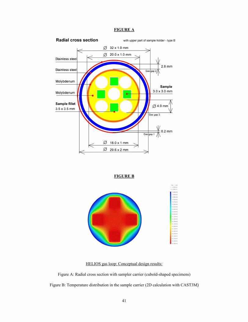
41
FIGURE A
FIGURE B
HELIOS gas loop: Conceptual design results:
Figure A: Radial cross section with sampler carrier (cuboïd-shaped specimens)
Figure B: Temperature distribution in the sample carrier (2D calculation with CAST3M)

42
5.2 WP2: In-core test device for material irradiation at high dose rate under controlled stress This device is dedicated to experiments at very high fast neutron flux such as:
• dose accumulation or irradiation growth of cladding and structural materials with on-line strain measurement (diameter, length …),
• axial stress relief test on blade sample with on-line load measurement,
• loading tests with strain measurement like diametral creep test under monitored internal pressure,
• in-core controlled dynamic tensile test,
• creep test with in-core stress increments, control of the biaxiality ratio and on-line measurement of axial and diametral strain,
Main features are : • Fast neutron flux range: 2.5 1014 - 5 1014 n.cm-2.s-1
• Maximum dose rate : 16 dpa/y
• Nominal temperature: up to 600°C
• Available space for sample holder: diameter 25 mm - length 800 mm,
• Maximum temperature discrepancy over the samples : 7,5°C,
• Typical sample material: Steel, Zirconium alloy, Nickel alloy, Titanium, Aluminum alloy The accurate temperature control of the samples is possible by means of a small in-pile loop of circulating fluid such as NaK. Indeed, an annular electromagnetic pump situated above the active zone allows the fluid flowing down after being previously pre-heated by the mean of electric heater situated just above the pump. Then the fluid is cooled down by a heat exchanger situated at the bottom of the rig.
Pneumatic material testing irradiation device: Sample multi-axial loading and axial / diametral strain
measurements (VTT concept)
LVDT sensor to measure axial displacement of tube
Mechanical connection rod between LVDT sensor and bellow’s bottom piston
P1 = Internal pressure
P2 = Bellows pressure
CEA device for measuring online changes in diameter

43
5.3 WP4: Fuel rod cluster irradiation under PWR conditions This test device is an experimental pressurized water loop designed to LWR fuel rod cluster testing in the JHR’s reflector. Typical samples are 6 to 8 segmented or re-fabricated fresh or pre-irradiated rods with a fissile length up to 600 mm and an external diameter up to 12.5 mm. It is dedicated to separate effect experiments on comparative characterization of fuel rods irradiated in the same PWR conditions: microstructure evolution, fission gas release and fission product distribution. It is designed for steady state irradiation, medium power transients as well as first phase of loss of coolant experiments (no high temperature and no quenching).
Because of this piping system stiffness, the in-pile rig is not adapted to displacement system of the reactor's reflector. Thus, the test rig should be placed in one specific experimental emplacement equipped with a variable thermal neutron screen that allows fuel rod power adjustments and medium speed transients Main features of this device are:
• Fast neutron unperturbed flux (> 1MeV): up to 2.5 1013 n.cm-2.s-1 • Thermal neutron unperturbed flux: up to 4.3 1014 n.cm-2.s-1 • Mean linear power of fuel samples : - nominal value : 200 W.cm-1
- maximum value : 400 W.cm-1
• Inlet coolant temperature: 300 +/- 20 °C • Maximum outlet coolant temperature : 340°C • Nominal coolant pressure : 155 bar
Figure A Figure B
Irradiation device for a PWR fuel rod cluster Figure A: Location of the device in the JHR core reflector
Figure B : Conceptual design of the device with a neutron shield
Neutron shield 5.8 mm (3He)
13.5 mm
98.3 mm
Neutron shield 5.8 mm (3He)
13.5 mm
98.3 mm
R fl P
T t
Gamma
d

44
Irradiation device for a PWR fuel rod cluster :
Effect of the peripheral tuneable neutron shield (3He):
Dpa/fission rate ratio versus the mean linear power of the rods for different 3He pressure in the shield (Tripoli 4 3D Monte Carlo simulation)
6. Conclusion The output and the added value of the JHR-CA is a consensus shared between European laboratories and user on a first level of specifications for the next generation of irradiation experimental devices and programmes. The technical work performed in 2004 in the Experts Group allowed to define together irradiation specifications and an irradiation device conceptual design for each workpackage. This work is now assessed by the Engineering team in terms of integration in the JHR facility, through two main objectives :
• to define the interfaces between the device and the facility (e.g. instrumentation and fluid lines, location within the core or in the reflector,….),
• to identify the critical points regarding the safety aspects.
After this assessment phase, an iteration will be done between the irradiation specifications, the conceptual design and the assessment results, to build-up a feasible experiment. Another output of this iteration is the determination of irradiation devices or components set, or instrumentation means to study in priority. For that reason, the following step after the JHR-CA has to address the detailed design of some of these devices and the reinforcement of the European collaboration on this field. For that purpose, it is proposed to launch an Integrated Infrastructure Initiative with the following objectives:
Test device in JHR reflector with a neutron shield (3He) Core : 100 MW - 34 fuel elements - 3x8 plates - UMo7 20% U5
Loop : 8 fuel rods - UO2 2% U5 - Core/center loop distance = 12.7 cm
0,00
0,20
0,40
0,60
0,80
1,00
1,20
1,40
0 100 200 300 400 500 600 700 800
Mean linear power (W/cm)
Fast
neu
tron
flux
/ Th
erm
al n
eutr
on fl
ux ra
tio
Structural material: zirconiumStructural material: stainless steel
0 b
40 b
5 b
10 b
20 b
0 b
40 b
10 b
radial power gradient in
device3He pressure
Regression curve
Fast neutron flux (> 0.907 MeV) / Thermal neutron flux (< 0.625 eV) ratio <=> dpa / fission rate ratio

45
• to drive technological innovation in the MTR field, with a mutual benefit for existing European MTRs and JHR,
• for the research activity, to develop some irradiation devices and/or key components, including test definition on existing MTRs,
• for the Transnational access, to offer access in existing MTRs for testing innovations; this contribute to the growth of present MTRs technological offer,
• For the networking activities, to address cross-cutting topics such as gauge calibration and conditioning, professional training.
7. References
[1] The Green Paper, “Towards a European Energy Security Strategy”, published by the European Commission in November 2000
[2] FEUNMARR, Future European Union Needs in Material Research Reactors, 5th FP thematic network, Nov. 2001 – Oct 2002
[3] C. VITANZA, D. IRACANE, D. PARRAT, Future needs for materials test reactors in Europe (FEUNMARR Findings), 7th International Topical Meeting on Research Reactor Fuel Management, ENS, RRFM 2003.

46
STATUS REPORT ON THE COST AND AVAILABILITY OF ENRICHED URANIUM FOR RESEARCH REACTORS
HANS MÜLLER and JÜRGEN LAUCHT Research Reactor Fuel Cycle Services
RWE NUKEM GmbH, Alzenau, Germany
ABSTRACT Availability and price development of enriched uranium contained in fuel elements for research reactors plays an important role with regard to reliability and economic and planning reasons. The leading price factors of LEU (19.75% enriched uranium metal), are the contained natural uranium equivalent in the form of UF6 (feed component), the separative work of the enrichment (SWU), conversion of the enriched uranium into metal form and associated services, such as transportation. World market price of feed material for enrichment was more or less stable in the last decades. After very moderate feed price increases between 2001 and mid-2003, the price gained momentum and almost doubled in the short period between the 2nd half of 2003 and year-end 2004.
This paper tries to give an answer to the question how the increased feed and SWU price affects the price and availability of LEU for research reactors. This paper deals also with the historic development of supply sources and origins of LEU, present status of supplies, price formulae, available stocks, value and advantages of fuel origin and return possibilities of spent LEU. 1. Introduction Mandatory for the operation of research reactors is the safe supply of fresh fuel and a viable option for the disposal of spent fuel. In the 1990s both the supply of fresh LEU and the take-back of spent fuel were adversely affected by the U.S. side due to a supply problem at the Y-12 plant and the lack of timely renewal of the U.S. Return Program for spent fuel. In the European Union (EU) the shortfall of supply from the US could be bridged by the use of no longer needed, considerable stocks of enriched uranium. This supply was organized by RWE NUKEM. The question is now whether a supply gap will again occur and whether research reactor operators can rely on a stable pricing for the needed LEU. 2. Historical development As in the past the major suppliers of LEU were Russia and the U.S. From the 1960s until the mid-1980s, the material supplied by the U.S. for production of fuel elements for research reactors inside and outside the USA was mainly highly enriched uranium (HEU). In the same period, the Soviet Union supplied HEU with enrichments from 36 to 90% U-235 in the form of fuel elements to Soviet-designed research reactors inside and outside the Soviet Union. In 1977, U.S. President Carter expressed concern about the widespread use of weapons-grade uranium in research reactors worldwide. In the same year, the USA launched a program to reduce enrichment in research reactors in Western countries in order to eliminate proliferation risks and misuse of HEU. The International Fuel Cycle Evaluation (INFCE) under Working Group 8 [10] recommended that the ideal U-235 assay for research reactor fuel should be less than 20%, namely 19.75%, in order to address the non-proliferation concerns of the U.S. In 1978, the U.S. installed a program to reduce the enrichment of research and test reactors (RERTR Program) under the lead of the U.S. Department of Energy (USDOE) and Argonne National Laboratories with the goal to convert all reactors with HEU fuel to LEU fuel and to reduce the annual export of U.S. HEU as a first step from 450 kg/a to 150

47
kg/a. After the end of the Cold War, Russia joined the RERTR Program with the same objective to reduce enrichment in Russian-supplied research reactors. Following the success and progress of the worldwide conversion program to replace highly enriched uranium (HEU) by low enriched uranium (LEU) the standard fuel for research reactors is uranium with an enrichment of 19.75% U-235 in the form of metal pieces. 3. Supply sources of LEU Today, LEU is mainly provided by the U.S. by using excess military stocks of HEU. The U.S. has discontinued the production of fresh HEU, and has major programs underway to reduce their surplus stockpiles of HEU. In Russia, HEU may still be produced for civil purposes (fast reactor and research reactor fuel). Through another international program Russia is selling uranium for power reactors below 5% U-235 derived from 500 tons of Russian surplus HEU to the USA, and the USA has a separate program to eliminate 174 tons of U.S. HEU that has been declared surplus. Together these programs are currently supplying up to 15% of the uranium demand for power reactors worldwide. The United Kingdom, France, and South Africa have discontinued all HEU production. 4. Annual demand for LEU The annual quantities of HEU needed to produce LEU for research reactors are relatively small. It is estimated that at present among the Western countries about 1 ton of LEU is being used to fuel already converted reactors. This quantity could increase to 2-3 tons if high flux reactors in the USA and the EU would be converted to LEU as well. The production of 3 tons of LEU would be equivalent to a dilution of approximately 600 kg of HEU (90% U-235). 5. LEU situation in the USA The U.S. surplus disposition program for 174 tons of HEU has allocated up to 10 tons of HEU for the production of LEU for research reactors for the period of 2002 to 2016. The LEU is generated by blending down of the HEU to LEU by melting in induction furnaces. The quantity of 10 tons of HEU is sufficient to produce more than 45 tons of LEU. 6. LEU situation in Russia No exact figures are available, but we have an information that the annual production of HEU fuel in Russia for research reactors inside and outside Russia was in the year 2002 approximately 850 kg with U-235 assays ranging from 20 to 90%.
7. Price factors for LEU The main price factors for enriched uranium for power reactors are the contained natural uranium equivalent in the form of UF6 (feed component), the separative work of the enrichment (SWU), conversion of the enriched uranium into metal form and associated services, such as transportation. Two factors, namely the natural uranium price and the SWU price, are market related prices and subject to changes. These changes are mainly due to the supply and demand situation, but partly also due to psychological factors, such as the mere perception of supply surplus or scarcity. The recent price shifts in the uranium market show that low prices for LEU - if really determined upon the market prices of the individual cost components - can be no longer taken for granted.
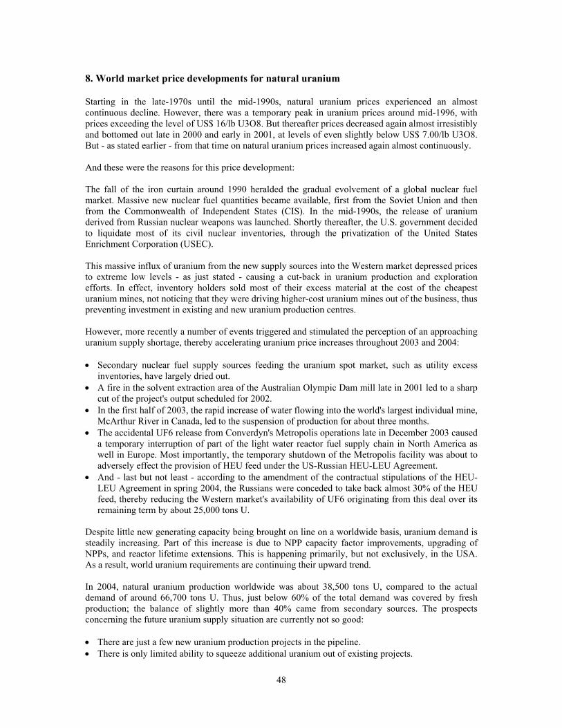
48
8. World market price developments for natural uranium Starting in the late-1970s until the mid-1990s, natural uranium prices experienced an almost continuous decline. However, there was a temporary peak in uranium prices around mid-1996, with prices exceeding the level of US$ 16/lb U3O8. But thereafter prices decreased again almost irresistibly and bottomed out late in 2000 and early in 2001, at levels of even slightly below US$ 7.00/lb U3O8. But - as stated earlier - from that time on natural uranium prices increased again almost continuously. And these were the reasons for this price development: The fall of the iron curtain around 1990 heralded the gradual evolvement of a global nuclear fuel market. Massive new nuclear fuel quantities became available, first from the Soviet Union and then from the Commonwealth of Independent States (CIS). In the mid-1990s, the release of uranium derived from Russian nuclear weapons was launched. Shortly thereafter, the U.S. government decided to liquidate most of its civil nuclear inventories, through the privatization of the United States Enrichment Corporation (USEC). This massive influx of uranium from the new supply sources into the Western market depressed prices to extreme low levels - as just stated - causing a cut-back in uranium production and exploration efforts. In effect, inventory holders sold most of their excess material at the cost of the cheapest uranium mines, not noticing that they were driving higher-cost uranium mines out of the business, thus preventing investment in existing and new uranium production centres. However, more recently a number of events triggered and stimulated the perception of an approaching uranium supply shortage, thereby accelerating uranium price increases throughout 2003 and 2004: • Secondary nuclear fuel supply sources feeding the uranium spot market, such as utility excess
inventories, have largely dried out. • A fire in the solvent extraction area of the Australian Olympic Dam mill late in 2001 led to a sharp
cut of the project's output scheduled for 2002. • In the first half of 2003, the rapid increase of water flowing into the world's largest individual mine,
McArthur River in Canada, led to the suspension of production for about three months. • The accidental UF6 release from Converdyn's Metropolis operations late in December 2003 caused
a temporary interruption of part of the light water reactor fuel supply chain in North America as well in Europe. Most importantly, the temporary shutdown of the Metropolis facility was about to adversely effect the provision of HEU feed under the US-Russian HEU-LEU Agreement.
• And - last but not least - according to the amendment of the contractual stipulations of the HEU-LEU Agreement in spring 2004, the Russians were conceded to take back almost 30% of the HEU feed, thereby reducing the Western market's availability of UF6 originating from this deal over its remaining term by about 25,000 tons U.
Despite little new generating capacity being brought on line on a worldwide basis, uranium demand is steadily increasing. Part of this increase is due to NPP capacity factor improvements, upgrading of NPPs, and reactor lifetime extensions. This is happening primarily, but not exclusively, in the USA. As a result, world uranium requirements are continuing their upward trend. In 2004, natural uranium production worldwide was about 38,500 tons U, compared to the actual demand of around 66,700 tons U. Thus, just below 60% of the total demand was covered by fresh production; the balance of slightly more than 40% came from secondary sources. The prospects concerning the future uranium supply situation are currently not so good: • There are just a few new uranium production projects in the pipeline. • There is only limited ability to squeeze additional uranium out of existing projects.

49
• Lead times of new mining and milling projects are lengthening, partly due to time-consuming Environmental Impact Assessments.
• Producers' willingness to invest in the extension of existing or the start-up of new mines is adversely affected by uncertainties over the timing of potential governmental sales of additional nuclear fuel, such as military uranium and plutonium.
• Exploration activities were extremely low in previous years. However, they buoyed up under the impression of recent uranium price increases.
9. What is the influence of increased natural uranium prices for LEU for research reactors? Although LEU is mainly produced by blending of HEU, the following pricing parameters could apply if one would adopt the pricing system for low enriched uranium for power reactors:
1 kg of 19.75% enriched uranium contains 47.324 kg of natural uranium equivalence and 37,783 separative work units (SWU), if proceeding on a tails assay of 0.3% U-235.
LEU Price = 47.324 x Unat price (US$/kg) + 37.783 x SWU price (US$) + conversion of UF6 to U metal (US$)
Prices of natural uranium (Unat) and separative work (SWU) are subject to market developments:
Average Unat price for the period 1997-2001: approx. 22 US$/kg UF6
Current Unat price: approx. 65 US$/kg UF6
Average SWU price 1997-2001: approx. 70 US$
Current SWU price: approx. 100 US$
Calculation of LEU price based on current market:
47,324 kg U (in UF6) x 65 $/kg U (UF6) = US$ 3,076
37,783 SWU x 100/SWU = US$ 3,778
The resulting price is US$ 6.854 per kg LEU in the form of UF6.
Additional cost for conversion from UF6 to U-metal applies when LEU is produced from UF6. However, while the conversion of enriched UF6 to UO2 as part of the power reactor fuel fabrication - with product assays below 5% U-235 - is done in industrial-scale facilities, the conversion of UF6 with assays up to 19.75% U-235 to U-metal is performed in very small conversion facilities with safe geometry and is subsequently very expensive. Thus, the price for this latter type of conversion is not at all comparable with the one for the conversion of UF6 to UO2 for power reactors.
Prices for such LEU conversion are not published and are subject to local conditions. According to RWE NUKEM’s experience, such conversion prices are in the range of US$ 2,000/kg U. This cost factor is not very much market related and could be assumed as constant cost (GDP related only).
As a result, the theoretical price of 1 kg LEU metal (19.75% U-235) would be US$ 8.854.
Since this price consists of 1/3 part of the cost for natural uranium, the LEU price will be depend on uranium market price movements. Quite some analysts predict that the current natural uranium price has still the potential of further growth, but that it should at least remain at its current high level. 10. How are the major LEU producers facing the new uranium prices? As a matter of fact, Russia and the U.S. being the major LEU producers have different ways of production: While the Russians use mostly fresh uranium for enrichment, the U.S. uses existing military HEU stocks for down blending. Accordingly, we have two different price calculation scenarios:
50
Russia has to take into account the elevated cost of natural uranium and separative work since they have to source the feed material and to provide enrichment services. Even conversion cost increases more in Russia than elsewhere since their GDP is higher than in Western states. As a result, the price of Russian LEU is relatively close connected to market prices. The US producer uses material from shelf which has been paid already in the past under military programs. Additional cost for down blending with the help of induction furnaces is non-market related internal cost. Since money earned from LEU sales has to be returned to the treasury (treasury owns the 10 tons HEU source for research reactor use), the sales price does not necessarily be at market price. Since USDOE has mostly agreed upon long-term requirements contracts with research reactor operators there is only little clearance for price increases (escalation clause). However, new contracts will certainly at least partially reflect the increased market prices for feed and SWU. 11. Conclusion Recent market price increases have influenced the market of power reactor uranium as well as for LEU for research reactors. The calculated market price for LEU with an assay of 19.75% U-235 as needed for research reactors rose within the last few years from about US$ 6,000 to US$ 8,800 now. This price is an indicator only. Reactor operators may see cheaper LEU prices, depending on quantity and availability of the requested material. Most important may be the date of commitment to a (long term) contract. All contracts concluded in the years before 2003 are earmarked with low prices and low escalation. New contracts may follow – at least partially – the uranium market price. Russian material follows close to the market price development of feed and SWU component contained in the LEU, since production is mainly made from fresh material.
US-origin LEU has a higher value than Russian-origin LEU (the difference is in the range of at least US$ 500 /kg U), since its return possibility is still a most interesting option. In spite of this known fact US material does not follow the market price factors (plus surcharge) since the LEU is produced from existing, paid HEU stocks. It might be part of the USDOE policy to offer LEU for attractive prices to keep control on the RERTR program and to attract the use of LEU rather then HEU. In principle Russian and US prices of LEU should be close together – with a premium of approximately 500 USD/kg for US material as long as return of spent fuel to the US is possible. About one thing the experts from uranium trading are quite sure: There are currently no indications for a price relaxation. A moderate scenario would be that prices remain at the current high level. As a consequence the LEU price for research reactors should follow this development unless policy demands for discounted prices. Well set are those reactor operators who have made long-term commitments in contracts which are not subject to the spot price development.

51
WHY A FAST FLUX FOR A RESEARCH REACTOR? THE PHÉNIX EXPERIMENTAL PROGRAM
J. GUIDEZ, L. MARTIN, J. DUMESNIL CEA / PHENIX Reactor
BP 17171, 30207 Bagnols-sur-Cèze, France Summary Phénix is the only fast breeder reactor in Europe available today for irradiation experiments. The neutron flux in the core is about ten times higher than those reached in other European research reactors (OSIRIS, HFR, BR2, R2,...) and has a fast neutron energy spectrum. The experimental conditions are described in this paper: flux, temperatures, monitoring and instrumentation. Phénix also provides irradiation devices such as irradiation rigs, containing for example up to 19 pins, able to be inserted inside special carrier sub-assemblies. Different carriers have been developed: fuel, breeder, steel assemblies. More recently some moderating carriers have been designed in order to optimise transmutation conditions for some heterogeneous target experiments. A hot cell, adjacent to the reactor is equipped with a wide range of non-destructive post irradiation examinations equipment for use with sub-assemblies and pins, for instance dimension measurements, eddy current testing, neutronography. The core characteristics make the reactor particularly suitable for experiments in the following fields: - transmutation tests which require high flux of high energy, - fuel and material tests for the future reactors developed in the Generation 4 framework, especially
all the fast reactors such as GFR, - and also all the material test for fusion programme (ITER) , for Accelerator Driven Systems and
even for Light Water Reactor (studies on internals for lifetime extension up to 60 years). The Phénix experimental programme involves irradiations in these various fields. It is presented here together with the related schedule with emphasis on the future experiments. They will include irradiation of high minor actinide content fuels, structure materials and fuel for Gen IV GFR concept. The experiments are conducted in the frame of a strong international co-operation specially with Japan and USA. The operation of the plant in 2004 is also described, and the future operating schedule of the plant. As a conclusion the Phénix programme demonstrates the very good complementarity of the reactor with the other research reactors in Europe. It shows also a large international scope involving customers from many R&D organisations. Introduction The French fast reactor prototype Phénix, with a nominal 145 MWe power rating (350 MWth), was started up again in July 2003 for 6 cycles, following a major safety upgrading and renovation. The specific experimental possibilities of a fast breeder reactor enable a wide scope of experiments. The Phénix experimental programme involves irradiations in the main following fields:
- Transmutation tests which require high neutron flux of high energy. - Fuel and material tests for the future reactors developed in the Generation 4
framework, especially all the fast breeder reactors such as GFR.

52
To begin with, this report describes the main experimental conditions, the irradiation devices as well as the non-destructive post irradiation examinations equipment. The current status of the Phénix experimental program, as well as the operation of the plan in 2004 are also presented. Experimental conditions at Phénix Neutron flux Phénix stands out from the other experimental reactors (OSIRIS, HFR, BR2 type …) due to the very high neutron flux (more than ten times higher than the reactors mentioned above) with a relatively hard spectrum (high energy) characteristic of the fast neutron reactors. The speed, or dose rates obtained are thus much higher than those in other reactors. Furthermore, the timely use of moderating materials can locally slow down the neutrons, thus benefiting from the high flux inherent to FBR, while increasing the effective cross-section of the neutrons. The following table summarizes the possibilities:
Fast flux
(n/cm2/s)
Thermal flux
(n/cm2/s)
Dose rate
PWR power reactor 1.3.1014 0.9.1014 2 dpa/year
OSIRIS, HFR, BR2 type research reactor
2 to 4.1014 4 à 7.1014 3 dpa/year
Fast spectrum 4.4.1015 18 dpa/6-month cycle
Type 1 moderate flux* 3.6.1015 12 dpa/cycle
Phénix reactor Type 2 moderate flux* 1.5.1015 3.7.1013 4 dpa/6-month cycle
* Types 1 and 2 correspond to the type of moderating carrier used Temperatures The irradiation of the inert materials (containing no fissile material) generally takes place at sodium temperature, between 380°C at the entrance to the core and 550° C average temperature at core outlet. However, to cover the new needs shown by gas-cooled reactors, an innovative device is being developed which allows for irradiating specimens up to 1000°C. This device is based on the use of the power left in the materials (samples, sample-holders and heating boxes) by the radiation and the neutrons, and the dimensioning of the gas gaps providing the thermal insulation between the heating boxes and the sealed containers. Measurements in the reactor The experiments are placed in the reactor core after passing through the sodium storage tank, referred to as the drum. In theory, there is no possible connection with the outside. This constraint sharply limits the possibilities of instrumentation and measurement.

53
The instrumentation commonly used includes measurements of sodium temperature at the entrance to and exit from the experimental set-up, radiological analysis of the sodium at the exit and mass spectrometry or gamma spectrometry analysis of the leakage gases. Two temperature measurement devices will be used in the high temperature setups currently being developed. The first is based on phenomena of the SiC reconstitution which occurs when the SiC is heated, after irradiation, to a temperature above or equal to its irradiation temperature. The second determines the maximum temperature reached during radiation, using a post-irradiation examination. This measurement device uses a stack of materials with increasing fusion temperature, arranged so that their successive fusion causes the stack to gradually decrease in height. Experimental setups The experimental sub- assemblies These are sub-assemblies similar to the standard fuel assemblies in the Phénix core, to which different types of changes have been made: - Nature of the structure materials (cladding, hexagonal wrapper, etc. …), - Nature or composition of the fuel, - Geometry of the pin or pellet, - Production process for a component, etc.… Most of these sub-assemblies are fissile, however, there can be breeder sub-assemblies and even control rods. This type of setup provides irradiation conditions which are very close to actual operation, yet which do not allow for any significant deviation from the standard design. The experimental sub-assemblies have primarily been used for experiments related to the development of the Fast Neutron Reactor system. The irradiation rigs The irradiation rig is complementary to the experimental sub-assembly. It is generally made up of a 40-mm diameter tube equipped with a sodium feed at the base and a locking and handling head which can contain a wide variety of experimental objects: - Phénix or other geometry fuel pins, able to hold standard or experimental fuel - Absorber pins - Specimens of materials intended for mechanical tests (tensile strength, resilience, toughness,
fatigue, creep, etc…) - Transmutation target, etc… The rings are irradiated inside special assemblies called “carriers ". The special feature of these sub-assemblies is their central channel into which the rig is inserted. There can be different types of carriers depending on the irradiation conditions being sought (fissile, fertile, steel, etc…). A new type of carrier has just been designed and made for the irradiation program. This carrier creates a zone of moderate neutrons around the rig, in the core or core periphery. The goal is to improve the transmutation performances of certain experiments. Highly innovative experiments can be conducted with these irradiation rigs. They offer a wide range of irradiation conditions both with respect to the neutron flow and its spectrum, and the irradiation temperature range. In addition, since their assembly and dismantling are possible in cell at Phénix, pins which have already been examined after one irradiation can be irradiated again.

54
Non-destructive testing in Phénix hot cell The hot cell is equipped with very comprehensive equipment for the non-destructive testing of sub-assemblies and pins. The beds are designed to accept a large variety of pins. Although the hot cell is a sealed and shielded chamber, it is not intended for the examination of fuel pellets by direct means, i.e. rupture of the pin claddings must be avoided so as not to disseminate fuel and fission products. Examination of the structure of sub-assemblies Several measuring beds have been developed to measure the length and deformation of irradiated sub-assemblies and in particular :
- A bed for measuring the characteristic dimensions of the assemblies. - A bed for measuring the flatness of wrapper tube faces.
These measurements are complemented by metallurgical tests un other CEA laboratories after cutting off samples into the cell. Pin examinations Theses analyses are to determine the behaviour of the pin cladding and the fuel pellets ant the interaction between them. The irradiated pins are also subject to several complementary tests. • Pin measurements
Deformations in the cladding, which has been subjected to neutron flux and high temperature, are measured.
• Eddy current testing This test enables the detection of cracks in the cladding as well as interactions between cladding and fuel. This bed consists of annular coils which move along the pin’s axis.
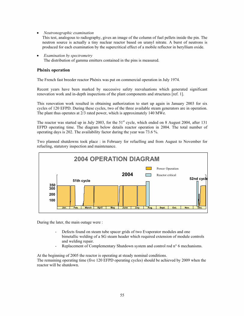
55
• Neutronographic examination
This test, analogous to radiography, gives an image of the column of fuel pellets inside the pin. The neutron source is actually a tiny nuclear reactor based on uranyl nitrate. A burst of neutrons is produced for each examination by the supercritical effect of a mobile reflector in beryllium oxide.
• Examination by spectrometry The distribution of gamma emitters contained in the pins is measured.
Phénix operation The French fast breeder reactor Phénix was put on commercial operation in July 1974. Recent years have been marked by successive safety reevaluations which generated significant renovation work and in-depth inspections of the plant components and structures [ref. 1]. This renovation work resulted in obtaining authorization to start up again in January 2003 for six cycles of 120 EFPD. During these cycles, two of the three available steam generators are in operation. The plant thus operates at 2/3 rated power, which is approximately 140 MWe. The reactor was started up in July 2003, for the 51st cycle, which ended on 8 August 2004, after 131 EFPD operating time. The diagram below details reactor operation in 2004. The total number of operating days is 202. The availability factor during the year was 73.6 %. Two planned shutdowns took place : in February for refuelling and from August to November for refueling, statutory inspection and maintenance. During the later, the main outage were :
- Defects found on steam tube spacer grids of two Evaporator modules and one bimetallic welding of a SG steam header which required extension of module controls and welding repair.
- Replacement of Complementary Shutdown system and control rod n° 6 mechanisms. At the beginning of 2005 the reactor is operating at steady nominal conditions. The remaining operating time (five 120 EFPD operating cycles) should be achieved by 2009 when the reactor will be shutdown.
2004 OPERATION DIAGRAM Power Operation
2004
350 300 200
Oct. Jan. Feb . March April May June July Aug. Sept. Nov. Dec.
100
51th cycle 52nd cycleReactor critical

56
Experimental irradiation program The experimental irradiation program conducted at Phénix has a two-fold purpose. It responds to the separation-transmutation directive 1 in the 30 Dec. 1991 law on radioactive waste management, and it supports the research on future system design. Figure 1 shows the position of the main experiments in the reactor core during the 51st cycle.
Figure n°1 Position of the main experiments in the 51st cycle core
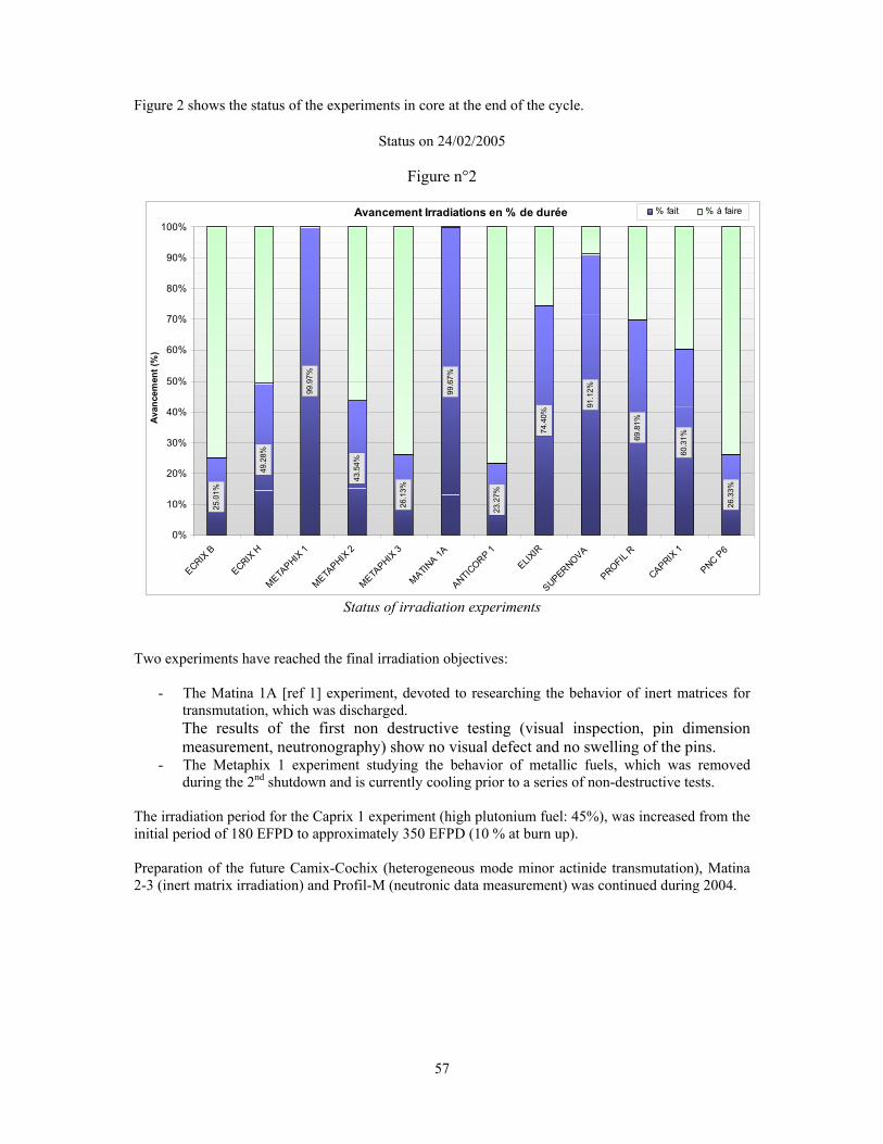
57
Figure 2 shows the status of the experiments in core at the end of the cycle.
Status on 24/02/2005
Figure n°2
Status of irradiation experiments Two experiments have reached the final irradiation objectives:
- The Matina 1A [ref 1] experiment, devoted to researching the behavior of inert matrices for transmutation, which was discharged. The results of the first non destructive testing (visual inspection, pin dimension measurement, neutronography) show no visual defect and no swelling of the pins.
- The Metaphix 1 experiment studying the behavior of metallic fuels, which was removed during the 2nd shutdown and is currently cooling prior to a series of non-destructive tests.
The irradiation period for the Caprix 1 experiment (high plutonium fuel: 45%), was increased from the initial period of 180 EFPD to approximately 350 EFPD (10 % at burn up). Preparation of the future Camix-Cochix (heterogeneous mode minor actinide transmutation), Matina 2-3 (inert matrix irradiation) and Profil-M (neutronic data measurement) was continued during 2004.
Avancement Irradiations en % de durée25
.01%
49.2
8%
99.9
7%
43.5
4%
26.1
3%
99.6
7%
23.2
7%
74.4
0%
91.1
2%
69.8
1%
60.3
1%
26.3
3%
0%
10%
20%
30%
40%
50%
60%
70%
80%
90%
100%
ECRIX B
ECRIX H
METAPHIX
1
METAPHIX
2
METAPHIX
3
MATINA 1A
ANTICORP 1
ELIXIR
SUPERNOVA
PROFIL R
CAPRIX 1
PNC P6
Avan
cem
ent (
%)
% fait % à faire

58
The first design elements of the three Futurix experiments were completed : - Futurix/FTA (FUels for Transmutation of transUranien elements in Phénix/Fortes Teneurs en
Actinides – High Actinide Content) irradiation experiment is part of a collaboration between the DOE, ITU, CEA and JAERI (Japanese Atomic Energy Research Institute). The DOE seeks to irradiate four fuels, including two zirconium-based metallic alloys, with and without uranium (U-Pu-Am-Np-Zr and Pu-Am-Zr) and two nitride fuels, also with and without uranium ([U,Pu,Am,Np]N and [Pu,Am,Zr]N). The ITU plans for two Ceramic-Metal type fuels, with a macromass base of (Am,Pu,Zr)O2 dispersed in a molybdenum (Mo) metallic matrix. The CEA proposes two Ceramic-Ceramic fuels of the (Pu,Am)O2 particles type micro-dispersed in a magnesia (MgO) matrix.
- Futurix/MI experiment to evaluate the behavior under irradiation and in temperature of inert materials (with no fissile matter) identified as potential candidates for the structure materials and the fuel elements of future fast reactors with gas coolant. These materials are made of carbide type ceramics (SiC, TiC, ZrC, …) or nitrides (TiN, ZrN, …), and refractory metals (Mo, Cr, …).
- Futurix/Concept : study of the behaviour of new fuel concept for the gas fast reactors. In addition, 2004 was the year of the decision to launch MATRIX, a new irradiation experiment whose objective is to study material behavior under irradiation and at low temperature of the structural materials (metals, ceramics) planned for the future systems (GCR, ADS, ITER). The CEA, the US Department Of Energy (DOE) and the European Union work together on this experiment. In 2004, work was primarily achieved on the definition of the experimental grid and design of the experimental setup. Conclusion 51st Phénix operating cycle was successfully achieved in August 2004. 52st cycle started in December after a planned shutdown for refuelling, maintenance and control. The first series of irradiation experiments devoted to minor actinide and long life fission products transmutation is well underway. Two experiments have completed their irradiation : Metaphix 1 (minor actinide transmutation with metal fuel) and Matina 1A (inert matrices). Their non destructive testing is being carried out. The second series of experiments which includes testing of materials and fuel for Generation IV systems is being designed and manufactured. Reference [Ref 1] J. GUIDEZ, L. MARTIN – CEA/Phénix Reactor 8th International Topical Meeting.
Research Reactor Fuel Management (RRFM).

59
BUSINESS OPERATIONS AND DECOMMISSIONING STRATEGY FOR IMPERIAL COLLEGE LONDON
RESEARCH REACTOR ‘CONSORT’ - A FINANCIAL RISK MANAGEMENT APPROACH
S.J. FRANKLIN Imperial College Reactor Centre
Imperial College London, Silwood Park Campus, Buckhurst Road, Ascot, SL5 7TE, UK
D. GARDNER, J. MUMFORD, R. LEA, J. KNIGHT PURE Risk Management Ltd
Silwood Park Campus, Buckhurst Road, Ascot, SL5 7PY, UK
ABSTRACT Imperial College London (IC) operates commercially a 100 kW research reactor, and as site licensee is responsible for funding both operations and eventual decommissioning. With long lead times ahead urgent decisions on the future business options have had to be made in 2004/5 including choices on whether to move to early decommissioning, recognising the high costs entailed, or to pursue continuing operations involving life extension measures such as refuelling. To develop a coherent overall approach strategy a financial risk driven programme was initiated to help define a robust transparent business and termination case for the reactor. This study was carried out in collaboration with a UK firm of financial risk experts, PURE Risk Management Ltd (PURE), working within a dedicated IC London reactor project team. This work evaluated immediate closure options due to financial constraints or life limiting failures, and options for continuing operation extending to 2028. Decommissioning and clean up were reviewed. Bespoke financial models created single value cost outputs and ranges of probabilistic net present values (NPV) for decommissioning costs and financial provisions to meet those costs at various levels of risk acceptance and regulatory compliance.
1. Introduction Many changes have occurred to the UK nuclear industry over the past 15 years. Nuclear research groups have closed, fast reactor programmes ceased, and the United Kingdom Atomic Energy Authority (UKAEA) changed emphasis to decommissioning. However, there is now at least some understanding that more investment is required in nuclear skills at all academic levels. Unfortunately, requirements for research reactors in this programme are not seen as the highest priority. Most UK research reactors and associated facilities have now closed. In 1997, the 100 kW CONSORT pool-type reactor [1] became the last civil nuclear research reactor surviving in the UK. The Reactor provides a research tool to IC and other UK research establishments and has an important commercial role in providing services to a wider market such as environmental analysis, isotope production (including essential provision for the national measurements system of primary standards), fission chamber power measurement calibration (supporting 16% of all UK energy generation), pharmaceutical development and medical analysis (supporting development of better drugs across the world). The Centre currently also provides nuclear engineering training to Mechanical Engineering undergraduates, postgraduates at three other UK educational establishments, the Health and Safety Executive, and others, such as (in 2003) the Russian nuclear safety regulator. This places IC is in an unrivalled position in the UK, and because of the customer base, before a decision is made to move to decommissioning, the transition will have to be handled with the care to preserve IC’s reputation.
60
Despite the above, IC has identified that the Reactor is not core to its current research and teaching activities. This leaves IC facing a stark choice - refuel in 2008-10 and continue business operations, or plan for earlier decommissioning. There are commercial considerations. The Reactor currently costs c. £600K per annum to operate - partly funded by providing commercial services to third parties. Despite every effort to close the revenue/costs the annual income is only c. £200K. The £400K deficit is met from College resources and is now considered unsustainable. Life extension refuelling would cost in the order of £1M and needs business justification. Other factors are that IC, as licensee, is legally obliged to pay for the decommissioning, demolition, cleanup and disposal an operation that will take some 4-5 years to complete. Cost estimates of £6.5-8M have been made. Part of PURE financial risk based objectives was refinement of these figures to demonstrate an understanding of the business impact and other risks on decommissioning strategy. 2. Influence of UK regulation The Conditions of the 1994 Nuclear Site Licence granted by the UK safety regulator, the Nuclear Installations Inspectorate (NII) of the Health and Safety Executive (HSE) requires IC to develop and enhance QA documentation related to all lifetime phases including decommissioning. Although it is recognised that the low power and low overall source term of CONSORT make it a special case, it nevertheless operates under the same 36 Site Licence Conditions (SLCs) as all other UK nuclear installations including BNFL Sellafield. Under approved arrangements [2] for the SLCs, detailed arrangements for SLC35 on Decommissioning are not required for this relatively low-hazard plant. Any work, which is done during the operational phase, is covered under arrangements for SLC 22 (Modifications). Radioactive discharges for operations and decommissioning are regulated by a separate agency called the Environment Agency (EA). 3. Decommissioning planning CONSORT is not unique in attempting detailed decommissioning planning and financial assessment. In UK law, there are a number of reasons why a proactive approach many years before ultimate shutdown, is adopted. The experience of CONSORT is illustrative. In 1999, Imperial College undertook a Periodic Review of Safety (PSR), required by the NII every 10 years, and by following College internally imposed arrangements [2]. The latter followed the format and recommendations of IAEA’s guidelines on Safety Assessment of Research Reactors and Preparation of the Safety Analysis Report [3]. Chapter 19 of the PSR report required an assessment of decommissioning plans. In addition, UK regulation places a number of Safety Assessment Principles (SAPs) [4], which are not relevant for this paper, except that of course, that safety and financial impact are interlinked. Pre-decommissioning strategy documentation is also required under a UK Government White Paper “Quinquennial Review of waste management on Nuclear Licensed Sites” [5] which requests operators to draw up strategies for the decommissioning of their redundant plant, including justification of the timetables proposed and the adequacy of the financial provision. Government policy is for HSE, in consultation with the EA, to review these strategies on a 5-yearly basis to ensure they remain soundly based. HSE aims to assess the proposed decommissioning strategy to determine whether it is adequately comprehensive, technically practicable and appropriately timed. In particular it considers whether the strategy is consistent with Government policy that ‘decommissioning should be undertaken as soon as it is reasonably practicable to do so, taking account of all relevant factors’, and also that the ‘hazards presented by the plant (or site) are reduced in a systematic and progressive way’. It also considers whether arrangements are in place to quantify the costs of decommissioning and to make available funds to undertake the work to the proposed timescales in order to assess ‘the adequacy of the financial provision being made to implement the strategy’. IC document [2] gave an overview of the facility and its operational activities, described the (then current) broad plans for decommissioning the reactor in 25 years time. This report described safety and management regimes expected for the decommissioning phase of the reactor, disposal routes for

61
radwaste, and gave the best-estimate time scales for decommissioning and associated threats to such timescales. At the previous issue. it was not aimed to provide the detailed technical assessment, which will be done when the decision to plan decommissioning on a short-term horizon is made. Financial discussions , together with some confidential aspects of radwaste disposal planning, were located in separate confidential Appendices. It is recognised that this document will go into more detail about what decommissioning will mean for IC at next issue. A subsequent 2002 report set out the findings of a review of this decommissioning strategy by NII, in consultation with the EA. HSE concluded in 2002 that cost estimates prepared by IC were indicative values based on its knowledge of recent decommissioning projects at other research reactors. HSE believed that IC has a broad understanding of the magnitude of its decommissioning costs but supports its undertaking to refine the estimates. IC has noted a contingent liability in its accounts and was considering how to translate this into a firm financial provision. HSE believed that IC’s financial position gives confidence that decommissioning can be taken forward on shorter timescales if necessary. 4. Other drivers for decommissioning planning Cost estimates of £6.5-8M had been made, but refinement was required, to include an understanding of the impact of business risks. An initial contract was placed in 2002 to determine the true costs of decommissioning, and break those down into work streams and cost the streams accordingly, to meet the HSE requirements. These confirmed that there were a significant number of items that were outside of IC’s control, and that had a significant ability to increase costs from a best estimate figure at the lower end of this range. A small risk register was created at this stage.
IC is investigating the options for managing the spent reactor fuel, for which no UK options exist, other fissile material, and intermediate level waste that will need to be transferred off the site and the destination for this material needs to be established. In addition, decommissioning will generate low-level radioactive waste, and Imperial College will need to ensure that there is an authorised disposal route for this material. There are many uncertainties associated with these areas that have the potential to impact the overall costs. A way of assessing the impact on costs was sought.
Early in 2004 IC agreed that the impact of financial risks on future business operations and overall termination strategy was essential to help identify the best strategic option and level of costs involved to deliver that option top the satisfaction of shareholders, regulators and other stakeholders.
5. The 2004 review of financial cost / Financial risk of nuclear business services and operations and a refuelling and decommissioning strategy for consort
CONSORT financial risks affecting 5 strategic options each with full plant decommissioning were identified and probabilistically modelled. This required creation of a comprehensive risk register that described key income and cost components of the business model. In addition a further 4 strategic options were assessed using a ‘no refuelling’ condition. Dynamic model outputs delivered Net Present Value forecasts at a 3% discount rate. Least cost strategic options were assessed. A decommissioning module delivered cost distributions, and enabled annual financial provisions necessary to meet those costs to be calculated. From these results College senior management were able to assess a range of see acceptable costs figures consistent with acceptable risk management, financial accounting and insurance standards. Financial models are highly flexible and transparent. Insights provided critical risk information that could lead to unplanned decommissioning occurrence. The PURE/ICRC project led to 3 key findings essential to ICRC CONSORT reactor planning: • A general strategy with no refuelling and efficiency improvement through additional cooling and
optimisation is shown to be financially dominant

62
• A mid-term planned closing date of 2017 is shown to give the best net present value consistent with income assumptions (from ICRC business and external funding opportunities for decommissioning) and technical life of the reactor with cooling; the approach is flexible, subject to review of assumptions
• An improved basis for covering the costs of decommissioning has been presented, through a rationale for provisioning for planned decommissioning which has been agreed with the Imperial College London auditors, and a risk model being used in discussions with potential nuclear insurers to cover further identified and quantified financial risks related to closure earlier than planned
6. Risk Register & risk mitigation A comprehensive risk register was created with 130 separate defined risks. 70 risks were operational risks and 60 risks associated with the business plan which are probability-based input variables and added to the deterministic model using CrystalBall® software to create a stochastic, risk based model. Four risks defined by the Risk Register and the modelling runs could cause early unplanned decommissioning. These risks have low probabilities of occurrence. But if they do occur, earlier decommissioning will be inevitable, without sufficient opportunity to fully provision for decommissioning costs. These risks are: loss of licence; significant accident; safety case obsolescence, and ‘Green’ pressures leading to early closure. ICRC is mitigating these risks. 7. Main findings of the financial risk assessment The overall conclusions and commentary are as follows: • A robust strategy for the CONSORT reactor is to continue commercial operations, not to consider
refuelling as an option, to investigate the use of artificial cooling and optimisation to improve reactor operational reliability, and to plan to decommission in the mid term, beginning around 2017.
• Decommissioning costs for a target date of 2017 and the financial provisions required to fund them at the 50 percentile expected cost are approximately £8.0 million in 2004 pounds. This assumes the decommissioning would be completed in 2021. Annual provisioning to meet this figure is approximately £400K based on an expected net fund growth rate of 3%. Provisioning up to the 65% level of the cost distribution would require an annual set aside of £412K.
• The cost of decommissioning will be accounted for by provisioning in Imperial College London annual accounts. The basis for this provision will be reportable to the external auditors and HSE (NII).
• Immediate closure in 2007 does not appear to be viable. There is a difficulty obtaining timely regulatory approval for such action (e.g. safety cases). Outstanding issues of intermediate level waste (ILW) management and spent fuel reprocessing will not be resolved in the short-term and these are in any case outside the control of Imperial College London. Early closure will not permit time to build up a reasonable decommissioning fund, nor to resolve possible funding from the NDA.
• A critical issue to any of the options studied is the ability of the business plan to deliver the revenues upon which the plan was predicated. Adoption of a mid-term option as foreseen will provide an opportunity to test if these revenues develop. A mid-course correction can be considered if revenues develop differently. The business plan projects operational surpluses which, if achieved, could make selection of a later date for decommissioning appropriate.
• A mid-term option also allows time to see if the potential benefits of funding liability externally by the Nuclear Decommissioning Authority (NDA) can be developed. The expected value of partial external funding distribution anticipated contribution of approximately £3 million. It should be noted that the distribution has a wide range, from zero to 100% of external funding. For Imperial College London accounting purposes no NDA assistance was assumed.
• The 2017 decommissioning strategy is based on planned closure. External insurance and/or self-insurance need to be considered to cover the risk of premature closure and enforced earlier decommissioning. At best, insurance will only cover fortuitous mechanical events.

63
• In addition, two alternative strategies for no refuelling with cooling were evaluated. These had decommissioning start dates of 2012 and 2028, with their own decommissioning costs and provisions.
8. Conclusions - How Imperial College interpreted the assessment In January 2005, the Management Board (MB) concluded that immediate closure in 2005-2007 does not indeed appear to be viable due to factors outside of its control. The MB noted that the 2017 decommissioning strategy is based on planned closure, and represented lowest Net Present Value cost to IC. The closure date for the purposes of provisioning for the 2003/4 financial accounts was brought forward from 2028 to 2017. However, they also identified that the Reactor is not core to its current research and teaching activities, and accepted a recommendation that the most appropriate option was to develop an exit strategy – a pre-decommissioning planning project – over the next three years, so that IC could finally shutdown in 2008, if it chose to do so. The model sensitivity to the business plan to deliver revenues has led to significant efforts to engage external users of the Reactor to secure additional funding in recognition of the strategic uses they make of the Reactor. In this regard stakeholders have asked to see an independent assessment of the business case before deciding to invest. The financial analysis described has been crucial in influencing stakeholders that the reactor will likely close if support is not given. A recommendation has now been made to support the development of a Supporters’ Club, albeit in parallel to development of an early exit strategy into decommissioning. Initial indications are that Supporters will provide a significant proportion of the £500K IC is seeking to realise for 2005/6. Subject to the business case developing in line with the plans for the Supporters’ Club and improvements to the business portfolio, IC will undertake an annual review on the Reactor Centre’s financial performance and its progress on decommissioning preparations. It is now up to the Supporters to persuade IC to keep the Reactor open for the provision of the services they need. Users will note that failure to form a successful Supporters’ Club will mean the loss of a unique facility. The bespoke financial model produced is flexible and has been delivered on CD-ROM. The model will therefore be re-run by IC to examine the impact of future change or data refinement. Review of the assumptions and outcomes of the model will be undertaken annually. The no-refuelling options recommended do not preclude decisions to close the reactor earlier than planned if the business plan does not deliver sufficient income. However, closure earlier than planned would leave a shortfall in provisioning which would need to be met in the four to five years following an early closure decision. 9. References [1] S.J. Franklin et al, Research Reactor Facilities & Recent Developments At Imperial College,
London“, Research Reactor Fuel Management 1998, ENS, Bruges
[2] “Arrangements for Compliance with Site Licence Conditions”, Prof.J.L.Head/M.J.Minski, Imperial College, RLSMP/01, Issue 1, January 1994.
[3] “Safety Assessment of Research Reactors and Preparation of the Safety Analysis Report”, IAEA Safety Series No. 35-G1, 1994
[4] “Safety Assessment Principles for NPPs”, HSE, 1992.
[5] “Review of Radioactive Waste Management Policy”, Government White Paper Cm2919, July 1995.
[6] “The Decommissioning Strategy For The Consort Reactor: 1999 Review”, S.J. Franklin, Imperial College, ICRC 140/21/01, Issue 2, March 1999.

64
HIGH-DENSITY U-Mo FUELS - LATEST RESULTS AND REORIENTED QUALIFICATION PROGRAMS
JAMES L. SNELGROVE1 Argonne National Laboratory
9700 South Cass Avenue, Argonne, IL 60439, USA
PATRICK LEMOINE Comissariat à l’Energie Atomique, Saclay
F-91191 Gif-sur-Yvette Cedex, France
LUIS ALVAREZ Comisión Nacional de Energía Atómica
Avda. Del Libertador 8250, C1429BNO Buenos Aires, Argentina
ABSTRACT
As a result of unstable swelling (pillowing) experienced during tests of U-Mo dispersed in aluminum under high-power conditions in 2003, the programs to develop, qualify, and license U-Mo dispersion fuels carried out in the United States, France, Argentina, and Russia have been reoriented. During the past year, a major effort has been carried out to determine the cause(s) of the failures and to find potential remedies for the problem. The past year’s activities are summarized and updated plans and schedules for the qualification of U-Mo fuels are presented.
1. Introduction This paper is the third in a series summarizing the status of work in the U.S., France, Argentina, and Russia to develop, qualify, and license U-Mo fuels [1,2]. Two years ago, plans were in place to perform qualification irradiations of full-sized fuel assemblies containing U-Mo dispersion fuels2 with densities up to 8 gU/cm3 in plates and 5.4 gU/cm3 in tubes. Expectations of success were high. By the end of 2003, however, it had become clear that U-Mo dispersion fuels had definite limitations under some conditions owing to a number of cases of unstable swelling (pillowing) experienced during irradiation tests in several countries. Last year’s paper reported a revamping of the various development programs to search for a solution to the unstable swelling problem being experienced in the dispersion fuels and to accelerate work on the development of fuel plates and pins containing solid U-Mo fuel meat (monolithic U-Mo fuel). It was projected that, at best, U-Mo fuel qualification would be delayed until around the end of 2010.
This past year has seen a number of changes in each country’s development program, as well as some significant organizational changes. The advent of the U.S. Global Threat Reduction Initiative (GTRI) last May resulted in the incorporation of the U.S. RERTR program into the broader GTRI program, along with the U.S. and Russian fuel repatriation programs. The GTRI goal of converting all Western-designed research reactors by 2013 and Russian-designed research reactors by 2014 resulted in increased pressure (and funding) for the U.S. RERTR program to accelerate qualification of the necessary fuels. The French U-Mo program is now focused on qualification of a U-Mo fuel for the
1 Argonne National Laboratory's work was supported by the U.S. Department of Energy, National Nuclear
Security Administration, Office of Global Nuclear Materials Disposition & Threat Reduction (NA-212), under contract W-31-109-Eng-38.
2 In this paper, “U-Mo dispersion fuel” refers to a fuel consisting of U-Mo fuel particles dispersed in an aluminum matrix, unless explicitly stated otherwise.
65
Jules Horowitz Reactor (JHR). The Russian program has experienced an apparent failure of one or more of the U-Mo dispersion fuel mini-pins being irradiated in the MIR reactor. As a result, the irradiation of full-sized pin-type and tube-type fuel assemblies in MIR is currently on hold. Irradiation of a U-Mo dispersion fuel element by the Argentine CNEA in its RA-3 reactor has been delayed.
Along with reorganization of program goals and schedules, the various programs have concentrated on searching for an understanding of the unstable swelling phenomenon and for a way to eliminate or, at least, mitigate the problem. This paper summarizes the current situation in the four programs.3
2. U.S. program The U.S. RERTR program has focused its efforts during the past year in three principal areas: (1) understanding the causes of the unstable swelling experienced in a number of irradiations of U-Mo dispersion fuels and ways to eliminate or mitigate the problem, (2) preparing for another set of miniplate irradiations in the Advanced Test Reactor (ATR) to test potential improvements to the dispersion fuel and to significantly increase the amount of irradiation data for monolithic U-Mo fuels, and (3) to improve and scale up the monolithic U-Mo fuel plate fabrication process. Even though significant effort is being expended on U-Mo dispersion fuel now, the long-term emphasis of the RERTR program is on monolithic U-Mo fuel because only it can provide the >8-gU/cm3 uranium density needed to convert a number of reactors in the U.S. and abroad. Development of irradiation-behavior models and codes is also being pursued both independently and in collaboration with the Argentine and French programs.
2.1. Investigations of unstable swelling in U-Mo dispersion fuel As reported at the 2004 RERTR International Meeting in Vienna, a concerted effort has been made to understand the cause of the unstable swelling problem and find a way to fix it [3]. Although the fundamental mechanism is not fully understood, the most important factors influencing the unstable swelling have been determined from the results of examinations of irradiated fuel samples. For example, it is certain that the unstable swelling results from fission gas generated in the fuel/aluminum interaction product. Although the extent of the interaction does not appear to be a controlling factor, a certain amount of interaction product is required to allow the growth and interconnection of large fission gas bubbles. In addition, the composition of the interaction product is very important—fission gas bubbles appear to be associated with an interaction-product phase having a larger aluminum concentration than those of the familiar UAl3 and UAl4 compounds. This is not surprising, since UAlx dispersion fuel is extremely stable under irradiation. The onset of unstable swelling is correlated to the local burnup (amount of fission gas present) and very strongly to the local fission rate; in fact, there appears to be a rather sharp fission-rate threshold for the onset of unstable swelling. The onset of unstable swelling does not appear to be correlated to the fuel-meat temperature, however.
A variety of tools have been employed in the search for a way to eliminate or mitigate the unstable swelling problem, including study of postirradiation examination (PIE) and out-of-pile experiment results and theoretical investigations. One potential remedy is to include silicon in the aluminum of the matrix. As Hofman et al. reported [3], the first clue that addition of silicon to the matrix aluminum is a possible remedy came from the observation that the amount of fuel/cladding interaction was less for Al 6061 cladding, which contains silicon in solution, than for AG3NE cladding, which does not. Also, the literature revealed that adding silicon to uranium-aluminum alloy suppresses the conversion of UAl3 to UAl4. Other possible remedies include the addition of elements such as zirconium, niobium, or titanium to the fuel, or even more effectively, using them to coat the fuel particles so the added element is at the fuel/aluminum interface where the interaction is occurring. Theoretical studies have confirmed the stabilizing effect of such additions to the aluminum matrix and to the U-Mo fuel. Another remedy being pursued is to replace the aluminum matrix with a magnesium matrix; a number of fabrication problems must be solved, however. As reported below, these possible remedies are 3 Owing to circumstances related to the reorganization of MINATOM into ROSATOM, a Russian author was not identified
in time for ROSATOM approval to be obtained. The information on the Russian program was prepared by author J. Snelgrove from knowledge gained as the U.S. technical coordinator of the joint U.S./Russian fuel development work and was edited by one of the Russian collaborators.

66
being investigated by the other national programs as well. A number of bilateral and multilateral discussions have occurred during the past year, and the U.S. RERTR program is participating in a number of bilateral collaborations.
2.2. Irradiation tests To investigate the effects of various additions to the fuel and matrix, to gain more information about the effect of fission rate, especially as a threshold parameter, and to provide the first data from ‘real’ monolithic U-Mo plates, a new set of miniplate irradiations will be performed in the ATR. The fuel plate size and the irradiation rig are based on those used for RERTR-4 and -5. RERTR-6 is a scoping test at moderate fission rate and burnup scheduled to start in April 2005. Only two different fuel alloys, U-7Mo and U-10Mo, are being used in this irradiation test. The dispersion fuel plates employ a number of different matrix aluminum alloys: 4043, 6061, and two binary compositions—0.5 and 2 wt.% silicon—in an attempt to counteract the unstable swelling detailed in the previous section. An unalloyed aluminum matrix is also being used as a known control. The monolithic fuel in the RERTR-6 test was fabricated using friction stir welding (FSW). Fuel foils of two different thicknesses, 250 and 500 μm, have been included in this experiment. RERTR-7 will be a similar scoping test at higher fission rate and burnup; it is expected to start several months after RERTR-6. In addition to the fuel types in RERTR-6, it will include dispersion fuel with a magnesium matrix. It will also contain monolithic fuel plates assembled by hot isostatic pressing (HIP) and transient liquid phase bonding (TLPB) if these techniques can be sufficiently developed in time. It is anticipated that RERTR-8 will be a short-duration, high-power test intended to provide data for peak, or off-normal, irradiation conditions.
In addition to the miniplate tests, which are intended to allow selection of the most-promising candidates for qualification, a series of full-sized plate tests are planned to confirm the results of the miniplate tests and to determine if there are any problems related to plate size, especially for the monolithic fuel. A series of full-sized assembly irradiations will follow. A major change in the U.S. program is its plan to make extensive use of the ATR for the full-sized plate and assembly irradiations instead of relying solely on foreign reactors.
2.3. Monolithic Fuel Fabrication Development During the past year, considerable progress has been made in the fabrication of monolithic fuel plates by FSW [4]. While it is continuing to investigate other fabrication techniques, HIP and TLPB, the RERTR program’s major emphasis in the coming year will be on scale-up of the FSW process. Foil-production scale-up is an issue that also must be addressed no matter what plate bonding process is used.
2.4. Schedule The RERTR program’s overall fuel development schedule is shown in Fig. 1.
3. French Program As the reference fuel solution for the Jules Horowitz Reactor (JHR) project, the development of an optimized and reprocessable LEU fuel is an objective of first importance for the French CEA [5]. The schedule of the project requires development of a suitable LEU fuel by the end of 2007 and the qualification of this fuel before the end of 2009. So, in order to reach these goals, the French CEA has launched a large program on the development of dispersion and monolithic U-Mo fuels, including out-of-pile investigations, manufacturing, irradiation and postirradiation programs, and code development. Manufacturing aspects are being developed in close collaboration with CERCA. Figure 2 presents a schematic view of the RJH fuel element.

67
3.1. Out-of-pile program The first development phase consists of out-of-pile investigations. A full scientific program has been created to increase our understanding of the U-Mo/Al interaction and to develop promising solutions to avoid inappropriate behavior during irradiation. Three items are being pursued in parallel:
• Thermodynamic studies to determine, through the U-Mo-Al ternary system, the phase equilibria at different temperatures;
• Out-of-pile metallurgical studies on diffusion couples to get a better understanding of the mechanisms of the U-Mo/Al interaction phenomena and to establish the parameters which could prevent this reaction; and
• Simulation studies to take into account the effects of irradiation using high-energy ion irradiation, typically 100-MeV xenon, in order to simulate the damage created by fission products. These experiments will be carried out on both the interdiffusion layer and the fuel meat from fuel plates.
The details of this program and the preliminary results of these investigations are presented in a later paper of this session [6].
3.2. Irradiation program The irradiation program is dedicated to evaluate optimized irradiation behavior on both U-Mo dispersion fuels and U-Mo monolithic fuels. As was done in the frame of the French UMo Group, these experiments will be made using full sized plates for recording the whole information package on manufacturing and irradiation aspects.
The first irradiation experiment (IRIS-3 experiment) is planned for testing parametrically the effect of adding silicon to the aluminum matrix. Two sets of plates were produced by CERCA using, respectively, Al2%Si and Al0,3%Si as the matrix. These plates began their irradiation in the OSIRIS reactor at the beginning of January 2005.
The next irradiation (IRIS-4 experiment) will evaluate a solution which could avoid the U-Mo/Al reaction by means of a protective layer on the particles themselves. Out-of pile studies are providing the basis for this approach by defining the protection layer and a way to produce it.
In parallel, the monolithic fuel solution will be tested in a U.S./French experiment on full-sized plates. Prototype U-Mo monolithic plates will be manufactured by Idaho National Laboratory (INL) and by CERCA with the technical support of CEA. They will be simultaneously introduced in the OSIRIS reactor early in 2006 (IRIS-5 irradiation). The first feasibility steps for manufacturing full-sized U-Mo foils are in progress in France and the U.S. Note also that CEA, CERCA, and TUM in Germany have signed a Memorandum of Understanding to support U-Mo fuel development.
The schematic schedule of this program is presented in Fig. 3, along with that of the RJH Fuel Project. Some more details of this program—manufacturing aspects and the irradiation schedule, for example—are presented in the next paper of this session [7].
3.3. Code development In parallel, CEA is developing a 2D thermo-mechanical code, called MAIA, for modeling the behavior of U-Mo dispersion fuel. MAIA uses a finite-element method to solve the thermal and mechanical problems. Physical models from the ANL code PLATE are used to evaluate the fission product swelling and the volume fraction of the U-Mo/Al interaction product. The swelling produces strains in the meat, which are imposed as the loading for the mechanical calculation. The fuel meat can be treated either elastically or plastically, and the Al alloy cladding can be either treated elastically or allowed to creep. Mechanical characterizations are in progress to improve the behavior modeling through a better knowledge of the material properties of the meat and the cladding. MAIA has been validated against the irradiations IRIS1, IRIS2, and RERTR-3, and rather good agreement with PIE results has been obtained. The results obtained are presented in later in this session [8].

68
4. Argentine program During 2004, the CNEA program for the development and qualification of high-density fuels for research reactors was strongly influenced by the unexpected unstable swelling experienced in qualification experiments performed by the other three programs discussed in this paper. Those experiments included full-sized fuel plate and miniplate irradiations. Because of the above-mentioned results, during this year the CNEA program was mainly focused on the investigation of the interaction between U-Mo and aluminum, the resultant interaction products, and the possible remedies to avoid the limiting phenomenon. The main activities were performed in the following fields: (1) chemical diffusion experiments using diffusion couples, (2) thermal compatibility studies using compacts, (3) development of technological solutions to reduce the amount of interaction, and (4) development of an alternative fabrication process to obtain very-high-density fuel plates.
4.1. Diffusion experiments As discussed earlier, experimental results had shown that the addition of silicon or, perhaps, magnesium to the aluminum of the matrix could have a beneficial effect on the characteristics of the interaction layer in the U-Mo dispersion fuel. Out-of-pile diffusion experiments were performed to evaluate the effect of the above mentioned additions [9]. These experiments were carried out at 550ºC and 580ºC, using aluminum alloys with magnesium and/or silicon as main alloying elements. Couples consisting of Al, U-Mo, and Al alloy were used to evaluate the influence of the alloying element and also to monitor the reproducibility of the experiments. According to [9] the main results obtained up to now may be summarized in the following points:
• The addition of Mg to pure aluminum does not produce any important change in the characteristics of the U-Mo–(Al+Mg) interaction zone. The composition of the layer is similar to the one obtained with pure aluminum.
• Silicon addition presented an encouraging result, as a (U-Mo)(Al,Si)3 phase appeared in the interdiffusion layer close to the aluminum. According to [9], this phase is similar to the one reported in silicide dispersion fuels in an aluminum matrix, which has a satisfactory behavior under irradiation.
• The interaction layer of the Al+Si alloy is not affected by the decomposition of the γU-Mo as happens when pure aluminum is used.
Figure 4 shows the result of the diffusion couple test with U-Mo/Al-Si. In this case, the interaction layer (IL) shows the above-mentioned (U-Mo)(Al,Si)3 zone. The next steps of the program in this field will include diffusion experiments under irradiation in the CNEA’s RA3 reactor.
4.2. Thermal compatibility studies Compacts obtained by standard powder-metallurgical fabrication procedures were also used to evaluate the influence of different alloying elements for the aluminum matrix of U-Mo dispersion fuel plates. Thermal compatibility tests were performed, submitting the compacts to thermal treatments reproducing different conditions of the fuel plate fabrication process. Temperature and time-at-temperature were the parameters initially considered. Measurements with a dilatometer and X-ray diffraction are being considered, among other techniques, for evaluation of the tests. Initially the tests were performed at 425ºC and 485ºC. Although the results are not yet fully evaluated, preliminary observations seem to show that the influence of temperature is consistent with results of the irradiation experiments (growth kinetics of the interaction layer). Additional tests using other matrix materials and fabrication conditions are scheduled for this year.
4.3. Development of technological solutions Two main technological alternatives to improve the feasibility of U-Mo utilization as a fuel material have been considered [10]. The first one is the use of particles coated with a multilayer diffusion barrier to reduce the amount of U-Mo/Al interaction in the dispersion fuel. Different materials, such as Al, Ge, Al-Si, and Mg-Al, are being considered for this purpose. The techniques that are being

69
tested are dip coating and chemical vapor deposition. Both techniques allow one to obtain layers a few microns thick. The coating process could be incorporated as one of the last steps of the powder production process. The other technological development is an alternative for the so called U-Mo monolithic fuel. To eliminate the presence of the undesirable interaction zone, Zircaloy cladding is being considered. The first rolling tests are being performed. If the results of these tests, and also of thermal compatibility and corrosion tests, are satisfactory, the next step of the program will be the fabrication of miniplates to evaluate the performance of this solution under irradiation.
4.4. Monolithic fuel fabrication development CNEA has been working also on the development of the FSW process to obtain monolithic U-Mo plates with aluminum cladding [11]. At the present stage of the development, the main task has been the optimization of operative parameters and the selection of the adequate tests to qualify the technique. It was possible to obtain satisfactory bonds with no defects or debonding at the interface for U-Mo foils. The method has already been used for the fabrication of diffusion couples. Considering the encouraging results obtained up to the present, one of the next steps of the program will be to evaluate the scale-up of the process to obtain full-sized fuel plates. 5. Russian program The Russian RERTR program has continued to work on development and testing of LEU fuel based on U-Мо alloys for two fuel assembly designs—one with tubular-type and the other with pin-type fuel elements. Work has continued on development of fabrication techniques for monolithic U-Mo fuel pins, on irradiation in the MIR reactor and PIE of U-Mo dispersion mini-pins, on irradiation of full-sized U-Mo dispersion pin-type fuel assemblies in the WWR-M reactor, and on PIE of the failed U-Mo dispersion fuel tubes irradiated in the IVV-2M reactor to ~60% average burnup. The principal accomplishments in three of these areas are summarized below. A much-more-detailed description of the Russian program results is presented in another paper later in this meeting [12]. 5.1. Irradiation and PIE of mini-pins at RIAR The irradiation of one of the capsules containing mini-pins in the MIR reactor at the Research Institute of Atomic Reactors (RIAR) continued until late in 2004, when fission products were detected in the experimental channel containing the experimental device with the highest-burnup pins. The average U-235 burnup in the mini-pins ranged between ∼60 and ~65%. This capsule has been cooling in the MIR pool, and disassembly and visual inspection is scheduled to take place in March 2005. The irradiation of the second capsule containing mini-pins was resumed and was completed early in February 2005 with average fuel burnup of the pins ranging between ∼20 and ~60%. The PIE of the pins removed after 20% burnup has been completed, and the pins appear to have behaved normally in every way. 5.2. Irradiation of two full-sized pin-type fuel assemblies in the WWR-M reactor The lifetime test of two full-sized pin-type fuel assemblies are in progress. Late in February 2005, the average burnup in the fuel assembly containing UO2-Al dispersion fuel (being irradiated as a control) was ∼35%, and that in the fuel assembly containing U-Mo dispersion fuel was 12%. The tests are planned to reach an average burnup of 60%.
5.3. PIE of failed fuel tubes at IRM The basic PIE of the U-Mo dispersion fuel tubes that failed at around 60% burnup in the IVV-2M reactor has been completed at the Institute of Reactor Materials (IRM). The nature of the failure appears to be the same as that of the failures that have been experienced in plates. Gamma scans of the tubes indicate the presence of a rather high flux gradient across the failed tubes during the latter part of their irradiation. Calculations are underway at ANL to determine if the local environment of the test assembly would have produced such gradients.

70
5.4. Irradiations of full-sized pin-type and tube-type U-Mo dispersion fuel assemblies The design and experimental and technological investigations for an IRT-type fuel assembly with pin-type fuel elements has been completed. The fabrication of experimental full-sized fuel assemblies of both tube-type and pin-type design is now planned for lifetime tests in the MIR reactor. These assemblies are prototypic of those which might be used to convert the WWR-SM reactor in Uzbekistan. Further work in this area is on hold, however, as the Russian program and its U.S. RERTR collaborators determine if changes in the planned irradiation program are needed as a result of the failures that have been experienced in pins and tubes. 6. Conclusion The past year has seen significant changes in the four national programs as a result of failures of U-Mo dispersion fuels. On the one hand, tests are planned (and have even started in France) of possible ways to eliminate the unstable swelling problem, the threshold of which seems to be strongly related to the fission rate. On the other hand, greater emphasis is being placed on the development of monolithic U-Mo fuels, which may be immune to the unstable swelling problem and which are needed for the conversion of several reactors.
7. References
[1] J. L. Snelgrove, P. Lemoine, P. Adelfang, and N. Arkhangelsky, “Qualification and Licensing of U-Mo Fuel,” Proceedings of the 7th Int’l. Topical Meeting on Research Reactor Fuel Management, Aix-en-Provence, France, March 9-12, 2003.
[2] P. Lemoine, J. L. Snelgrove, N. Arkhangelsky, and L. Alvarez, “UMo Dispersion Fuel—Results and Status of Qualification Programs,” Proceedings of the 8th Int’l. Topical Meeting on Research Reactor Fuel Management, Munich, Germany, March 21-23, 2003.
[3] G. L. Hofman, M. R. Findlay, and Y. S. Kim, “Postirradiation Analysis of Low Enriched U-Mo/Al Dispersion Fuel Miniplate Tests, RERTR-4 and -5,” 26th Int’l. Meeting on Reduced Enrichment for Research and Test Reactors,” Vienna, Austria, November 7-12, 2004.
[4] C. R. Clark, T. C. Wiencek, M. R. Finlay, R. L. Briggs, D. M. Wachs, S. L. Hayes, G. L. Hofman, and C. J. Mothershead, “Update on Fuel Fabrication Development and Testing at Argonne National Laboratory,” 26th Int’l. Meeting on Reduced Enrichment for Research and Test Reactors,” Vienna, Austria, November 7-12, 2004.
[5] P. Lemoine, F. Huet, B. Guigon, C. Jarousse, and S. Guillot "JHR Fuel development and Qualification Programs," 26th Int’l. Meeting on Reduced Enrichment for Research and Test Reactors,” Vienna, Austria, November 7-12, 2004.
[6] S. Dubois, F. Mazaudier, F. Huet, J.-P. Piron, P. Martin, J. C. Dumas. H. Noël, C. Jarousse, P. Lemoine, "Out of pile French Research Program on the UMo/Al System: First Results," These Proceedings.
[7] J.-M. Hamy, P. Lemoine, F. Huet, C. Jarousse, and J.-L. Emin, “The French UMo Group Contribution to New LEU Fuel Development,” These Proceedings.
[8] V. Marelle, F. Huet, and P. Lemoine “Mechanical calculations on U-Mo Dispersion Fuel Plates with MAIA,” These Proceedings.
[9] M. Mirandou, M. Granovsky, M. Ortiz, S. Balart, S. Aricó, and L. Gribaudo, “Reaction Layer Between U-7wt%Mo and Al Alloys in Chemical Diffusion Couples,” 26th Int’l. Meeting on Reduced Enrichment for Research and Test Reactors,” Vienna, Austria, November 7-12, 2004.
[10] E. Pasqualini and M. López, “Increasing the Performance of U-Mo Fuels,” 26th Int’l. Meeting on Reduced Enrichment for Research and Test Reactors,” Vienna, Austria, November 7-12, 2004.

71
[11] P. Cabot, A. Maglioni, M. Mirandou, and S. Balart, “CNEA Experiments to Apply Friction Stir Welding to Encase U-Mo Foils in Al,” 26th Int’l. Meeting on Reduced Enrichment for Research and Test Reactors,” Vienna, Austria, November 7-12, 2004.
[12] I. Dobrikova, A. Vatulin, A. Morozov, and V. Suprun, “Main Results and Status of the Development of LEU Fuel For Russian Research Reactors,” These Proceedings.
8. Figures
Fig. 1. Schedule of RERTR fuel development activities
Fig. 2. Schematic view of JHR fuel element
Miniplate Irradiations and PIE (ATR)
RERTR-6
RERTR-7
RERTR-8 ?
Full-Sized Plate Irradiations & PIE
OSIRIS
ATR
‘Element’ Testing & PIE
ATR (MTR Mini-Elements)
Non-U.S. Reactors
2006 2007 2008 2009 2010 2005 2011
Fuel Performance Modeling
Fabrication Development
Fuel Qualification
Curved fuel plate
Stiffener
Central position
Aluminium tube
JHR fuel element
Uranium load : 4.8 to 8 gU/cm3
Active height : 600 mmWater channel : 1,84 mm Cladding : Aluminium alloyStructure : 3x8 platesInternal diameter : circa 37 mmExternal diameter : circa 95 mm

72
2003 2004 2005 2006 2007 2008 2009 2010 2011 2012 2013 2014RJH definition studies
Issue for Preliminary Safety ReportOut of pile & in pile analytical studies
IRIS-3 irradiation (UMo/Al+x%Si)IRIS-4 irradiation (UMo coated particles)
IRIS-5 irradiation (UMo foils)Plate Irradiations in RJH conditions
Reference UMo solution Backup U 3 Si 2 solution
Issue for RJH fuel choiceFull sized RJH Fuel Elements Irradiation
Issue for Safety Report & Qualification ReportFuel Processes Industrialization
First core manufacturing
Final tests (active & inactive)First critically
Fig. 3. Schematic schedule of the JHR Fuel Project
Fig. 4. Result of diffusion couple test with U-Mo/Al-Si; the interaction layer (IL) shows the above-mentioned (U-Mo)(Al,Si)3 zone
U-Mo
Al
IL
Si

73
THE FRENCH UMo GROUP CONTRIBUTION TO NEW LEU FUEL DEVELOPMENT
J.M. HAMY Framatome ANP(*)
69456 Lyon Cedex 06, France
P. LEMOINE CEA Saclay
91191 Gif-sur-Yvette Cedex, France
F. HUET CEA, Cadarache
13108 St-Paul-Lez-Durance Cedex - France
C. JAROUSSE CERCA (**)
Les Berauds, B.P. 1114, 26104 Romans Cedex - France
J.L. EMIN COGEMA (AREVA Group)
BP 4, 78141 Vélizy Villacoublay Cedex - France
(*) an AREVA and Siemens company, (**) a subsidiary of Framatome ANP, an AREVA an Siemens company
ABSTRACT The French UMo Group was based on a close collaboration between CEA and AREVA's companies strongly involved in the MTR field. The aim of this program was to deliver industrially a high performance LEU UMo fuel able to be reprocessed, and suitable for a wide range of Research Reactor, covering the expected needs for MTR next generation. Since 1999, the program has been focused on industrial aspects with the intention to deal with the whole fuel cycle: manufacturing, irradiation behaviour, fuel characterisation, code development and reprocessing validation. It has been based on the fabrication of full-sized U-7%Mo fuel plates with a density up to 8 gU/cm3. The dedicated and advanced R&D means provided by the CEA have been used intensively with the contribution of HFR and BR2 facilities in Europe. This paper presents a synthesis of the program and the corresponding significant results obtained. These results have played a major role as regards the UMo dispersion fuel qualification route by issuing, for the first time, evidence of severe performance limitations. Consequently, the global international effort to develop and qualify a high density LEU UMo fuel has been definitively rerouted and forced to overcome these discrepancies by exploring new technical solutions. A French extended program sustained by a CEA and CERCA collaboration has been launched in 2004 in order to develop a suitable UMo fuel solution. UMo dispersion and monolithic fuel are both investigated through three new full-sized plate irradiations planned in OSIRIS.
1. Introduction During the last five years, the French UMo Development program has brought a significant contribution to the international effort to qualify a new LEU fuel that allows the conversion of

74
research reactors by achieving high performance and offering reprocessing capabilities. On the basis of the US RERTR program leaded by ANL, and the numerous parametric studies using small plate irradiation experiments and examinations, the LEU U-Mo dispersion fuel was identified as the more suitable candidate. Taking into account this statement issued from the R&D side, the French UMo Group (FUMoG) has resolutely oriented its development program to a global approach covering the whole fuel cycle taking advantage of a strong synergy between CEA and AREVA. In that way, this program encompasses manufacturing aspects, irradiation of full-sized plates, characterization of irradiated fuel, code development for modelling the behaviour of UMo dispersion fuel and reprocessing validation [1]. Advanced R&D facilities has been dedicated to this program by the CEA : IRIS irradiation device for full-sized plates, OSIRIS for the irradiation experiments, LAMA and LECA hot cells laboratories for PIE, ATALANTE facility for reprocessing validation of spent fuel, with the additional contribution of HFR and BR2 facilities in Europe. A synthesis of the different technical domains managed through this program is presented bellow, together with the corresponding significant results obtained. The unexpected performance limitations that have been revealed for the first time are also expressed with the direct consequence to necessarily reroute the international effort to develop and qualify high density LEU UMo fuel. The new French UMo extended program that will investigate new solutions is presented with the corresponding time schedule.
2. Manufacturing aspects Since the beginning of the development program, CERCA has played a major role, acting intensively to supply diverse UMo full size plates for the different irradiation experiments implemented, producing the plates in a very efficient way that has allowed the continuation of the program in accordance with the expected milestones [2], [3]. Early in 1999, full-sized UMo plates have been manufactured for the first time by CERCA and were dedicated to IRIS-1 and UMUS irradiation experiments. Theses plates were based on UMo powder produced by grinding that induced a mean porosity higher than 10%. In 2002, CERCA was able to produce a new set of full-sized plates for IRIS2 and FUTURE experiment in a very short time. Theses plates were produced using atomized UMo powder and the associated mean porosity was found at a level below 3 %. Along the program, CERCA has spent a sustained R&D effort to comfort and adapt its proprietary advanced process for plate manufacturing, initially developed for highly loaded U3Si2 plates with densities up to 6 gU.cm-3. Progress has also been made regarding quality control methods available. CERCA has clearly demonstrated its ability to manufacture full-sized plates and elements for high density (up to 8 gU.cm-3) UMo dispersion fuel. Due to this large experience, CERCA is ready to extend this know-how and master complementary techniques needed to overcome the present performance limitations encountered (see section 6).
3. Main results of irradiation experiments The French UMo development program has performed four irradiation experiments on full-sized plates with increasing surface heat flux and clad temperature (see Table 1). The values tested, as regards the heat flux, have been ~140 W/cm2 for IRIS-1 experiment, ~240 W/cm2 for UMUS and IRIS-2, and ~340 W/cm2 for FUTURE. The extensive program of post irradiation examinations has confirmed the very good behaviour of the high uranium loading UMo7 and UMo9 plates of IRIS-1, with a peak burn-up of 67% that corresponds to 240 full power days and a cladding surface temperature below 75°C [4]. The UMUS experiment was stopped after two cycles due to the failure of the 35%-enriched plates related to uncontrolled oxide (boehmite) thickness on the cladding [5]. FUTURE experiment was stopped at the end of the

75
second cycle by the detection of an abnormal thickness increase in the hot spot region (local burn-up of 33%). It revealed for the first time severe performance limitation of UMo dispersion fuel for higher irradiation flux. Large porosities appear in the U-Mo/Al interaction phase leading to an excessive swelling that is amplified in an irreversible process by the increase of the local temperature. IRIS-2 experiment results recently obtained are presented in [6]. In spite of less severe operating conditions than FUTURE ones, IRIS-2 experiment was definitively stopped at the end of the fourth cycle. The maximum swelling admissible value of 250 µm, defined for safety reason, was reached for one plate at the end of the third cycle and at the end of fourth cycle for the two remaining plates. PIE examinations are consistent with the FUTURE results. Large pore developments are observed in the interaction product, that induces the pillowing of the plates. The origin of the phenomenon is not completely established and different hypothesis are still discussed [6]. The decrease of the aluminium content in the interaction compound versus the increase of the temperature is pointed out. The role of the fission products is also mentioned. In addition the results show that for IRIS-2 the pillowing of the pates corresponds to a fission density of 2.1021 f.cm3
UMo (consistent with FUTURE), but for IRIS-1 with lower irradiation conditions and grinded particles no pillowing was observed up to 4.8 1021 f.cm3
UMo. All these unique and crucial results, which correspond to unacceptable restrictive limitations for the UMo dispersion fuel, were revealed for the first time by the FUMoG to the MTR community at the end of 2003. Complementary results have been given during the first quarter of 2004. These results have definitively imposed to reroute the international effort to develop and qualify a high density LEU UMo fuel and have forced to overcome these discrepancies by exploring new technical solutions (see section 6).
Experiment IRIS-1 UMUS IRIS-2 FUTURE Reactor OSIRIS (Fr) HFR (Neth) OSIRIS (Fr) BR2 (B)
Number of full-sized plates 3 2 / 2 4 2 U-Mo powder Grinded Grinded Atomized Atomized
Enrichment (% 235U) 19.75 19.75 / 35.00 19.75 19.75 Fuel loading (g U/cm3) 8.0 8.0 8.3 8.0
As-fabricated meat porosity (%) 11-13 11-13 1.1-1.5 1-2 Max. heat flux at BOL (W/cm2) 140 175 / 250 238 340
Max. cladding temperature at BOL (°C) 75 90 / 110 93 130
Coolant velocity (m/s) 9 8 9 12 Status of experiment Complete Failed Stopped Stopped
Number of irradiation cycles 10 2 4 2 Total duration (full-power days) 240 48 60 40
Average burn-up at EOL (% 235U) 50 15 30 25 Max. local burn-up at EOL (% 235U) 67 20 40 33
Table 1: French program irradiations on full-sized plates.
4. Reprocessing qualification The definition and the validation of the UMo fuel reprocessing process is a key point to confirm the advantage of UMo fuel as regards the back-end aspect. Although the reprocessing feasibility of UMo has been demonstrated since 1998, a research and development program has been performed by COGEMA and CEA, as part of the French UMo development program, to study and adjust more precisely the operating condition to reach the industrial feasibility. The process is based on a specific dissolution in nitric acid media in order to obtain a dissolution solution that allows the dilution into standard UOx type fuel dissolution solution. The resulting solution has to be compatible with an adaptation of the Purex process for the U and Pu purification.

76
The main aspect to be investigated is the solubility of Mo as a function of the temperature and the U, Al, HN03 mass fraction. The first tests have been conducted on unirradiated UMo powder. Then pieces of fresh UMo plates have been used for the dissolution tests [7]. The last results obtained on irradiated materials coming from the IRIS-1 experiment made in OSIRIS are presented in [8]. These tests performed at the ATALANTE facility (CEA Marcoule) show that only the Al concentration can limit the Mo solubility that affects the fuel dissolution rate to guarantee a solution free of precipitate. The recommended parameters have been defined. The dissolution kinetics of unirradiated and irradiated materials have been precisely investigated. Very similar values have been observed for both types of material. The interaction product UMoAlx does not influence the dissolution kinetic. The validation of the operating parameter for the reprocessing the irradiated UMo fuel plates is one of the most important result issued by the French UMo development program. This is the confirmation of the favourable properties of UMo fuels as regards the key point of the back-end solution. COGEMA will pursue the optimisation of the process and will expertise the new solutions that are envisaged to overcome the present performance limitation of UMo fuel (see section 6) in order to make sure that the reprocess criteria will still be satisfied.
5. Thermo-mechanical simulation of UMo behaviour Characterization of fresh fuels, and post irradiation examinations based on IRIS-1, FUTURE and IRIS-2 have issued an important data base that allows the definition of the proper physical laws applicable to UMo dispersion fuel behaviour. The thermo-mechanical MAIA, that is a 2D finite element computational code developed by CEA, is used to combine the physical laws and determine the global behaviour on the fuel [9]. The meat is assumed to be a homogeneous material. Thermal and thermo-mechanical calculations take into account swelling effects (minored by as-fabricated porosities), growth of the interaction compound and diffusion of the Al matrix. The improvements introduced in the last version of MAIA are presented in [10]. The model of the interaction compound evolution is issued from the PLATE code developed by DOE-ANL and the mechanical model have been extended and made more consistent with the expected results. IRIS-1 and RERTR-3 post-irradiation results have been used to validate MAIA with a good accordance as regards interaction layer thickness and volume fractions evaluation. MAIA has been applied to do analysis on one IRIS-2 UMo plate, in order to anticipate the final PIE results. Mechanical analyses have been done considering various constitutive laws to facilitate the understanding of the results [10]. MAIA is a useful tool that has been made consistent with the different results obtained as regards UMo dispersion fuel behaviour. It is an interesting feature of the French Umo development program that offers a synthesis of the physical results obtained and helps for the analysis and the understanding of the in-reactor fuel behaviour.
6. The French UMo Extended Program (CEA/CERCA) As the reference fuel solution for the Jules Horowitz Reactor project –JHR project– the development of an optimised and reprocessing LEU fuel is an objective of first importance for the CEA. In order to strengthen and contribute actively to the international development of a suitable UMo fuel solution, CEA and CERCA has launched a large UMo development and qualification program [11]. After five years of UMo development CEA & CERCA agreed to pursue their investigation for contributing and challenging the nowadays difficulties encountered along the UMo fuel qualification way. Sharing fruitfully their motivation as well as skills CEA and CERCA signed in June 2004 a collaboration agreement for studying and developing a suitable UMo fuel solution. This section states the technical selected steps of the CEA program including the CERCA developments on manufacturing aspects, and gives the associated preliminary schedule.

77
6.1 Out of pile investigation The first development phase has been defined as an out of pile phase investigation. This basic step will bring the fundamental knowledge to further understand (U,Mo)Alx interaction product formation which is led, at least, by the temperature. Two sub phases have been identified by CEA. Within the determination of the U-Mo-Al ternary diagram system at various temperatures, thermodynamic information will be obtained. Compounds identification associated with their characterization will determine how the U-Mo-Al reaction is led. In another hands, diffusion couples were produced for understanding the kinetics and the direction path of the interaction. With the help of such heat treated samples, various solutions could be easily investigated and the most promising idea selected for the next evaluation phase. The preliminary results are given in [12]. According to these results and prior publication as well [13] Si addition incorporated into the aluminium matrix could be of interest for reducing the (U,Mo)Alx interaction. Nevertheless promising "cold solution" is just track which has to be investigated up to the end for the final in pile verdict. 6.2 Irradiation experiments Supported by the studies stated above, the irradiation program –See figure 1– is dedicated to evaluate optimized UMo dispersion fuels and UMo monolithic as well. As already done for recording the whole information package –Manufacturing and irradiation aspects– these experiments are going to be made using full size plates. The first experimentation is for testing parametrically the Si effect addition into the aluminium matrix. Two sets of plate were produced by CERCA using respectively Al2%Si and Al0,3%Si aluminium matrix. Plates were introduced in CEA OSIRIS reactor at the beginning of 2005 (IRIS-3 experiment). The following experimental irradiation (IRIS-4 experiment) will evaluate a solution which could avoid the (U,Mo)Alx reaction by means of a protective layer on the particles themselves. Out-of pile studies are sustaining this approach by defining the protection layer and the experimental way of production. Finally, monolithic fuel solution which seems to be a good candidate [14] will be tested with IRIS 5 irradiation. Our goal, at this step, is to produce monolithic full size plate prototypes for firstly learning the manufacture of such fuel concept and also for evaluating the fuel behaviour under irradiation. Monolithic UMo Plate prototypes manufactured by Argonne National Laboratory will be simultaneously introduced with the French CEA/CERCAs plates. If the manufacture of UMo dispersion fuel is industrially mastered by CERCA, industrial monolithic fuel production is not yet setting-up. Two main issues have been identified and the associated program already launched. In order to save time "fashionable" manufacturing techniques will be used: UMo foils are going to be produced by means of conventional rolling and plates -as proposed by ANL- by means of FSW –Friction Stir Welding–. Nevertheless, for long term consideration, some more industrial techniques will be simultaneously investigated. The first feasibility step for manufacturing UMo foils is in progress – The raw UMo material has been already manufactured by CEA- and the production will be over before mid 2005. A full FSW program is being launched for evaluating industrially this technique. The IRIS-5 experiment is scheduled early at the beginning of 2006. PIEs will be carried-out by CEA.

78
6.3 Time schedule
UMo fuel investigation programOut-of pile investigationAluminium matrix study -Si-U-Mo-Al ternary diagramMicrostructure investigation
Plates manufacturing -achieved-Irradiation -In progress-PIEs
Feasability studies and plate manufacturingIrradiationPIEs
Feasability studies and plate manufacturingIrradiationPIEs
2008
IRIS 3 Irradiation Al2%Si and Al0,3%Si matrix
IRIS 4 irradiation UMo "coated" particles
IRIS 5 Irradiation Monolithic UMo fuel -ANL and CERCA plates-
2004 2005 2006 2007
Figure 1: French UMo (CEA/CERCA) extended program
7. Conclusion After the French UMo Group development program completion and the issue of unacceptable results, and in the frame of developing a suitable fuel for the CEA RJH reactor project, CEA and CERCA signed in 2004 an agreement in order to find solution which could prevent the nowadays redhibitory UMo fuel behaviour. UMo dispersion and monolithic UMo fuel monolithic are both investigated through the program. For monolithic UMo form, a specific program has been launched for testing the manufacturing feasibility and finaly for producing prototype full size plates which will be irradiated in OSIRIS reactor early in 2006. Irradiation of UMo dispersion plates are also scheduled for evaluating the proposed solutions. 8. References [1] JM. Hamy, P. Lemoine, F. Huet, B. Guigon, C. Jarousse, JL. Emin, "Status as of March 2004 of
the French UMo Group development program", 8th International Topical Meeting on Research Reactor Fuel Management, München, Germany, March 21-24, 2004.
[2] C. Jarousse, JP. Durand, Y. Lavastre, M. Grasse, "CERCA UMo development status as of March 2003", 7th International Conference on Research Reactor Fuel Management (RRFM 2003), Aix-en-Provence, France, March 9-12, 2003.
[3] C. Jarousse, Y. Lavastre, M. Grasse, "CERCA's experience in UMo fuel manufacturing", Proceedings of the 25th Int. Meeting on RERTR, Chicago, USA, October 5-10, 2003.
[4] F. Huet, B. Guigon, P. Lemoine, C. Jarousse, F. Witjsma, G. Dassel, G. Hofman, J. Snelgrove "The UMUS failure : Facts and analysis", 7th International Conference on Research Reactor Fuel Management (RRFM 2003), Aix-en-Provence, France, March 9-12, 2003.

79
[5] F. Huet, V. Marelle, J. Noirot, P. Sacristan, P. Lemoine, "Full-sized plates irradiation wit high UMo fuel loading – IRIS 1 experiment", Proceedings of the 25th Int. Meeting on RERTR, Chicago, USA, October 5-10, 2003.
[6] Huet, J. Noirot, V. Marelle, S. Dubois, P. Boulcourt, P. sacristan, S. Naury, P. Lemoine, "Post irradiation examination of UMo full sized plates – IRIS2 experiment", these proceeding
[7] A. Juvenelle , Transactions of International. Conference on Research Reactor Fuel Management (RRFM 03), Aix en Provence, France, March 9-12, 2003.
[8] N. Herlet, G. Ferlay, JP. Dancausse, A. Juvenelle, "Reporcessing U-Mo spent fuels : dissolution experiment on unirradiated and irradiated materials", these proceedings.
[9] V. Marelle, F. Huet, P. Lemoine, “Thermo-mechanical modelling of U-Mo fuels with MAIA”, 8th International Topical Meeting on Research Reactor Fuel Management, München, Germany, March 21-24, 2004.
[10] V. Marelle, F. Huet, P. Lemoine, "Thermomechanical modelling of U-Mo fuels with MAIA", these proceedings.
[11] P.Lemoine, F.Huet, B.Guigon, C.Jarousse and S.Guillot "JHR Fuel development & qualification programs" RERTR'04 Vienna, Austria, 2004.
[12] S. Dubois, F. Mazaudier, F.Huet and All "Out of pile French research Program on the UMo/Al system: First results" this proceedings.
[13] G.L.Hofman, M.R.Finlay, Y.S.Kim, "Post-irradiation analysis of Low enriched UMo/Al dispersions fuel miniplate tests, RERTR4 & 5", International Meeting on Reduced Enrichment for Research and Test Reactors (RERTR), Vienna, Austria, 7-12 November 2004.
[14] C.R Clark, T.C Wiencek and All, "Update on fuel fabrication development and testing at Argonne national laboratory", International Meeting on Reduced Enrichment for Research and Test Reactors (RERTR), Vienna, Austria, 7-12 November 2004.

80
MAIN RESULTS AND STATUS OF THE DEVELOPMENT OF LEU FUEL FOR RUSSIAN RESEARCH REACTORS
A. VATULIN, A. MOROZOV, V. SUPRUN, I. DOBRIKOVA Federal State Unitary Enterprise
A.A.Bochvar All-Russian Scientific Research Institute of Inorganic Materials (VNIINM) 123060 Moscow, P.B. 369, Russia
ABSTRACT VNIINM develops low enrichment uranium (LEU) fuel on base U-Мо alloys and a novel design of pin-type fuel elements. The development is carried out both for existing reactors, and for new advanced designs of reactors. The work is carried on the following main directions: − irradiate LEU U-Mo dispersion fuel (the uranium density up to 6,0 g/cm3) in two
Russian research reactors: MIR (RIAR, Dimitrovgrad) as pin type fuel mini-elements and in WWR-M (PINP, Gatchina) within full-scaled fuel assembly (FA) with pin type fuel elements;
− finalize development of design and fabrication process of IRT type FA with pin type fuel elements;
− develop methods of reducing of U-Mo fuel –Al matrix interaction under irradiation; − develop fabricating methods of fuel elements on base of monolithic U-Mo fuel. The paper generally reviews the results of calculation, design and technology investigations accomplished by now.
1. Introduction The main direction of the Russian RERTR program is to develop fuel on high-density uranium alloys base. Currently, the main option is the dispersion U-Mo fuel. Two types of FA are under development to use this fuel: 1) standard design with tubular type fuel elements with up to 5.4 g/cm3 U density; 2) novel design with pin type fuel elements with up to 6.0 g/cm3 U density.
The paper gives a generalized review of the results of development of FA with pin type fuel elements on base U-Mo fuel [1-8]. During the recent years this direction is advanced. The work is being performed as assigned by RosAtom and "TVEL". Many organizations in Russia, i.e. RDIPE, RIAR, NPCC, PINP, RSC KI as well as ANL (USA) participate in the work in the frame of the international program RERTR.
2. Main results During 2004 the developments of pin type fuel elements on base LEU U-Mo fuel were carried out in the following major directions: – irradiate dispersion U-Mo fuel in two research reactors: MIR (RIAR, Dimitrovgrad) in pin type
fuel mini-elements and WWR-M (PINP, Gatchina) within the full-scaled FA with pin type fuel elements;
– master the design and fabricating process the IRT type FA with pin type fuel elements; – develop methods of reducing of U-Mo fuel –Al matrix interaction under irradiation; – develop fabricating methods of fuel elements with monolithic U-Mo fuel.
To-day the following results are available on those work directions.
The irradiation of pin type fuel mini-elements with dispersion U-Mo LEU fuel has been completed in MIR reactor [2, 3, 5, 6]. The mean U235 burnup in the fuel mini-elements made up ∼ 40-65%. The

81
results of the post-irradiation experiments (PIE) are planned to be available in the autumn of 2005. This experiment will provide the first irradiation results of pin-type U-Mo dispersion fuel elements in characteristic operation conditions of pool-type research reactors. The design of the experimental device is illustrated in Fig.1. The main testing conditions are summarized in Tab.1 [3, 5, 6]. The experimental device have 13 types of fuel composition that are differed by the uranium density, the chemical composition of the alloy, the method used to fabricate fuel granules and the phase state of the alloy.
Fig.1. Experimental device: 2 capsules with fuel mini-elements
The process of testing included four stages (Tab.1). After the first stage (January, 2004) at the mean fuel burnup of ∼20% one capsules (N2) was discharged from the reactor to unload some mini-elements for preliminary investigations. At the second stage (during three months) only one capsule (N1) was under irradiation. In April 2004 mini-elements in capsule N2 were replaced by fresh fuel elements, and the capsule N2 was loaded into the reactor once again. At the third stage of the tests in the channel the indicators of nonhermeticity were fund out and so late in November capsule N1 was discharged at the mean fuel burnup up to ∼60-65%. The irradiation of capsule N2 was resumed and completed early in February 2005 at the average fuel burnup of ∼20-60%.
Currently, the primary investigations of the mini-elements of capsule N1 are in progress including: inspection of appearance, γ-scaning and measurements of the mini-element dimensions.
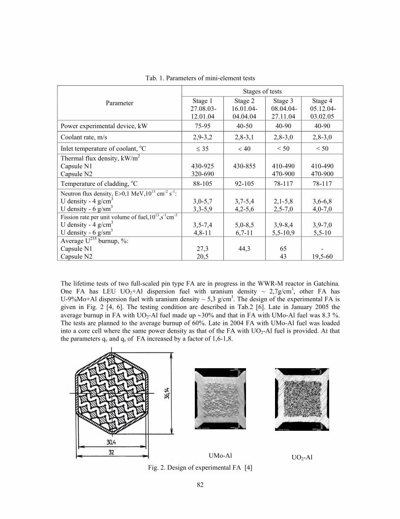
82
Tab. 1. Parameters of mini-element tests
Stages of tests
Parameter Stage 1 27.08.03-12.01.04
Stage 2 16.01.04-04.04.04
Stage 3 08.04.04-27.11.04
Stage 4 05.12.04-03.02.05
Power experimental device, kW 75-95 40-50 40-90 40-90
Coolant rate, m/s 2,9-3,2 2,8-3,1 2,8-3,0 2,8-3,0
Inlet temperature of coolant, оC ≤ 35 < 40 < 50 < 50 Thermal flux density, kW/m2
Capsule N1 Capsule N2
430-925 320-690
430-855
410-490 470-900
410-490 470-900
Temperature of cladding, оC 88-105 92-105 78-117 78-117 Neutron flux density, E>0,1 MeV,1013 cm-2 s-1: U density - 4 g/cm3 U density - 6 g/sm3
3,0-5,7 3,3-5,9
3,7-5,4 4,2-5,6
2,1-5,8 2,5-7,0
3,6-6,8 4,0-7,0
Fission rate per unit volume of fuel,1013,s-1cm-3 U density - 4 g/cm3 U density - 6 g/sm3
3,5-7,4 4,8-11
5,0-8,5 6,7-11
3,9-8,4
5,5-10,9
3,9-7,0 5,5-10
Average U235 burnup, %: Capsule N1 Capsule N2
27,3 20,5
44,3
65 43
-
19,5-60
The lifetime tests of two full-scaled pin type FA are in progress in the WWR-M reactor in Gatchina. One FA has LEU UO2+Al dispersion fuel with uranium density ~ 2,7g/cm3, other FA has U-9%Mo+Al dispersion fuel with uranium density ~ 5,3 g/cm3. The design of the experimental FA is given in Fig. 2 [4, 6]. The testing condition are described in Tab.2 [6]. Late in January 2005 the average burnup in FA with UO2-Al fuel made up ∼30% and that in FA with UMo-Al fuel was 8.3 %. The tests are planned to the average burnup of 60%. Late in 2004 FA with UMo-Al fuel was loaded into a core cell where the same power density as that of the FA with UO2-Al fuel is provided. At that the parameters qv and qs of FA increased by a factor of 1,6-1,8.
UMo-Al
UO2-Al Fig. 2. Design of experimental FA [4]
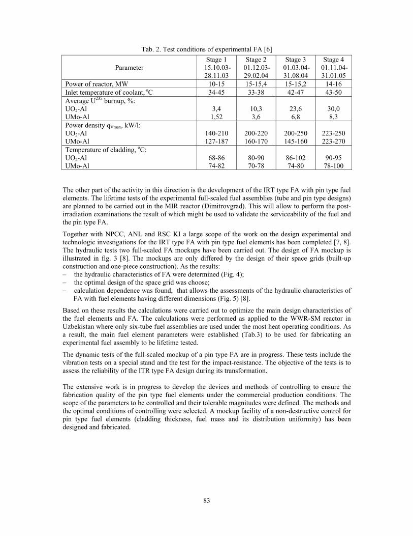
83
Tab. 2. Test conditions of experimental FA [6]
Parameter Stage 1
15.10.03-28.11.03
Stage 2 01.12.03-29.02.04
Stage 3 01.03.04-31.08.04
Stage 4 01.11.04-31.01.05
Power of reactor, MW 10-15 15-15,4 15-15,2 14-16 Inlet temperature of coolant, оC 34-45 33-38 42-47 43-50 Average U235 burnup, %: UO2-Al UMo-Al
3,4 1,52
10,3 3,6
23,6 6,8
30,0 8,3
Power density qVmax, kW/l: UO2-Al UMo-Al
140-210 127-187
200-220 160-170
200-250 145-160
223-250 223-270
Temperature of cladding, оC: UO2-Al UMo-Al
68-86 74-82
80-90 70-78
86-102 74-80
90-95 78-100
The other part of the activity in this direction is the development of the IRT type FA with pin type fuel elements. The lifetime tests of the experimental full-scaled fuel assemblies (tube and pin type designs) are planned to be carried out in the MIR reactor (Dimitrovgrad). This will allow to perform the post-irradiation examinations the result of which might be used to validate the serviceability of the fuel and the pin type FA.
Together with NPCC, ANL and RSC KI a large scope of the work on the design experimental and technologic investigations for the IRT type FA with pin type fuel elements has been completed [7, 8]. The hydraulic tests two full-scaled FA mockups have been carried out. The design of FA mockup is illustrated in fig. 3 [8]. The mockups are only differed by the design of their space grids (built-up construction and one-piece construction). As the results: – the hydraulic characteristics of FA were determined (Fig. 4); – the optimal design of the space grid was choose; – calculation dependence was found, that allows the assessments of the hydraulic characteristics of
FA with fuel elements having different dimensions (Fig. 5) [8].
Based on these results the calculations were carried out to optimize the main design characteristics of the fuel elements and FA. The calculations were performed as applied to the WWR-SM reactor in Uzbekistan where only six-tube fuel assemblies are used under the most heat operating conditions. As a result, the main fuel element parameters were established (Tab.3) to be used for fabricating an experimental fuel assembly to be lifetime tested.
The dynamic tests of the full-scaled mockup of a pin type FA are in progress. These tests include the vibration tests on a special stand and the test for the impact-resistance. The objective of the tests is to assess the reliability of the ITR type FA design during its transformation. The extensive work is in progress to develop the devices and methods of controlling to ensure the fabrication quality of the pin type fuel elements under the commercial production conditions. The scope of the parameters to be controlled and their tolerable magnitudes were defined. The methods and the optimal conditions of controlling were selected. A mockup facility of a non-destructive control for pin type fuel elements (cladding thickness, fuel mass and its distribution uniformity) has been designed and fabricated.

84
Tab. 3. Main parameters of pin type fuel elements of IRT FA
Parameter Value Dimension of fuel meat, mm 1,75 x 1,75 Active part length, mm 600 Cladding thickness, mm
nominal minimal
0,4 0,3
Circumscribed diameter, mm
4,5
U-235 mass, g in fuel element in FA
2,2 380
U density, g/cm3 6,1
Fig. 3. Design of IRT pin type FA mockup
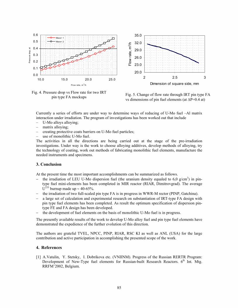
85
0.0
0.1
0.2
0.3
0.4
0.5
0.6
10.0 15.0 20.0 25.0
Flow rate, m 3/h
Pre
ssur
e dr
op, a
t
Макет 1
Макет 2
20.0
23.0
26.0
29.0
32.0
35.0
2 2.5 3
Dimension of square side, mm
Flow
rate
, m3 /h
Fig. 4. Pressure drop vs Flow rate for two IRT
pin type FA mockups Fig. 5. Change of flow rate through IRT pin type FA vs dimensions of pin fuel elements (at ΔP=0.4 at)
Currently a series of efforts are under way to determine ways of reducing of U-Mo fuel –Al matrix interaction under irradiation. The program of investigations has been worked out that include – U-Mo alloys alloying; – matrix alloying; – creating protective coats barriers on U-Mo fuel particles; – use of monolithic U-Mo fuel. The activities in all the directions are being carried out at the stage of the pre-irradiation investigations. Under way is the work to choose alloying additives, develop methods of alloying, try the technology of coating, work out methods of fabricating monolithic fuel elements, manufacture the needed instruments and specimens. 3. Conclusion At the present time the most important accomplishments can be summarized as follows. − the irradiation of LEU U-Mo dispersion fuel (the uranium density equaled to 6,0 g/cm3) in pin-
type fuel mini-elements has been completed in MIR reactor (RIAR, Dimitrovgrad). The average U235 burnup made up ∼ 40-65%.
− the irradiation of two full-scaled pin type FA is in progress in WWR-M rector (PINP, Gatchina). − a large set of calculation and experimental research on substantiation of IRT-type FA design with
pin type fuel elements has been completed. As result the optimum specification of dispersion pin-type FE and FA design has been developed.
− the development of fuel elements on the basis of monolithic U-Mo fuel is in progress.
The presently available results of the work to develop U-Mo alloy fuel and pin type fuel elements have demonstrated the expedience of the further evolution of this direction. The authors are grateful TVEL, NPCC, PINP, RIAR, RSC KI as well as ANL (USA) for the large contribution and active participation in accomplishing the presented scope of the work. 4. References
[1] А.Vatulin, Y. Stetsky, I. Dobrikova etc. (VNIINM). Progress of the Russian RERTR Program:
Development of New-Type fuel elements for Russian-built Research Reactors. 6th Int. Mtg. RRFM’2002, Belgium.

86
[2] A.Vatulin, Y.Stetsky, V.Suprun, etc.(VNIINM). Russian RERTR Program: Advanced LEU fuel development for research reactors. 24th Int. Mtg. RERTR’2002, Bariloche, Argentina, November 2002.
[3] V.A.Starkov, G.Gataullin etc.(RIAR) Substantiation of the conditions of in-pile tests of LEU high density fuel for research reactors. 7th Int. Mtg. RRFM’2003, Aix-en-Provence, France, March 2003.
[4] A.Vatulin, A. Morozov, Y.Stetsky, I.Dobrikova etc. (VNIINM). Major results on the development of high density U-Mo FUEL and pin-type fuel elements executed under the Russian RERTR program and in cooperation with ANL (USA). 25th Int. Mtg. RERTR’2003, Chicago, USA, October 2003.
[5] A.Vatulin, A. Morozov, I.Dobrikova etc. Development of IRT type fuel assembly with pin-type fuel elements for LEU conversion of WWR-SM research reactor in Uzbekistan. 8th Int. Mtg. RRFM’2004, Munich, Germany, March 2004.

87
CURRENT STATUS OF THE CNEA QUALIFICATION PROGRAM
FOR THE FABRICATION OF HIGH DENSITY MTR FUEL
L. ALVAREZ, N. BOERO and J. FABRO
Unidad de Actividad Combustibles Nucleares Comisión Nacional de Energía Atómica (CNEA)
Avda. del Libertador 8250, C1429BNO - Buenos Aires, República Argentina [email protected]
ABSTRACT The Atomic Energy Commission of Argentina (CNEA) is actively working in a program to qualify the fabrication of high-density MTR nuclear fuels since the year 2000. The first part of the program, already completed, was the qualification of the silicide fuel fabrication. Irradiation, post-irradiation examination and hot cell destructive testing were the main activities carried out to complete this part. The second part deals with the qualification of the fabrication of fuel elements bearing the fissile material in a disperse U-Mo compound. In view of the results obtained by other irradiation programs part of the CNEA effort was put on the basic research to look for an improvement in the understanding of the interaction phenomena. Diffusion studies were performed to search for a suitable matrix material to reduce the U-Mo-Al interaction. The above mentioned results also indicate that a stable behaviour is likely to be expected at low power-low temperature conditions. Based on this consideration a full-scale irradiation program in the Argentine RA-3 Reactor is again being analyzed.
1 CNEA Qualification Program The Atomic Energy Commission of Argentina (CNEA), as was reported in previous RRFM meetings [1-3], is actively working since the year 2000 in a program to qualify the fabrication of different high-density MTR nuclear fuels. The first part of the program, already completed, was the qualification of the silicide fuel fabrication. Fuel design, fabrication, irradiation, pool-side post-irradiation examination and hot cell destructive testing were the main activities developed to fulfil the objectives of this stage. The fuel assemblies involved in this part of the program were irradiated in the Argentine Reactor RA-3 reaching in both cases the foreseen target burnup without any signal of defects or abnormalities. The second stage of the program deals with the qualification of the fabrication of fuel elements bearing the fissile material as a U-Mo compound. This part of the program was delayed in view of the unexpected results obtained in another programs regarding the onset of interaction between U-Mo and Al. The third part, which is still in a development stage, will cover the fabrication of plates with U-Mo as a monolithic fuel. 2 Current activities As a consequence of the results obtained in irradiation experiments performed by other organizations [4, 5] the full scale fabrication of U-Mo disperse fuel and its qualification was momentarily postponed during the last year to wait for more information and a better understanding of the U-Mo fuel behaviour under irradiation. CNEA activities were mainly concentrated in the study of fuel aluminum reaction rates and interaction products characterization, exothermic fuel-aluminum-reaction energy release and fuel-aluminum thermal compatibility. Part of the effort was applied to the development of
88
possible solutions to reduce the interaction phenomena. The modification of the material for the matrix of the compacts and the coating of the U-Mo particles are considered as the more suitable solutions. The development of fabrication techniques for monolithic fuel plate fabrication like Friction Stir Welding and the rolling of monolithic plates using zircaloy to replace de Al cladding are also new fields of development. Irradiations of miniplates in the RA-3 and in the ATR to test these solutions are also being planned. 3 Basic and applied research results The recent results of CNEA research activities in the interaction field were presented elsewhere [6]. The main conclusions are summarized in the following points: • The addition of Mg to the pure Al does not produce any important change in the characteristics of
the U-Mo–(Al+Mg) interaction zone. • Si addition produces the presence of a (U,Mo)(Al,Si)3 phase in the Al side of the interdiffusion
layer. This phase is similar to the one reported in silicide dispersion fuels, which has a satisfactory behaviour under irradiation.
• The interaction layer of the Al+Si alloy is not affected by the decomposition of the γU-Mo as
happens when pure Al is used. 4 Continuation of U-Mo fuel fabrication developments and qualification The results reported in the last RRFM and RERTR Meetings indicate that the irradiation behaviour of the U-Mo alloy is very stable and predictable [5]. At high power densities the interaction phase formed by interdiffusion of U-Mo and Al matrix develops large fission gas pores but this undesirable behaviour is not present at low power and low temperature conditions. Figure 4 of [5] shows a threshold delineating satisfactory and unacceptable fuel behavior of the U-Mo/Al plate type tests performed to date. Based on this threshold and considering that the RA-3 operating conditions are well below the mentioned curve, in the satisfactory region, a new irradiation of a U-Mo fuel in the main Argentine Research Reactor is again being analyzed. In the mean time CNEA has continued working in setting-up the fuel plate fabrication techniques to reduce the amount of interaction present in the as-fabricated plate and to improve the homogeneity of the U distribution in the fuel plate. CNEA fabrication techniques are prepared to obtain sound plates suitable for irradiation. 5 The program As mentioned in 4, a full-scale irradiation program in the Argentine RA-3 Reactor with the objective of qualifying the technology for the fabrication of full scale disperse U-Mo fuel plates is being analyzed. The fuel fabrication will be performed in the ECRI facility at the Constituyentes Atomic Center and the target burnup will be >50 %. The RA-3 reactor, located near Buenos Aires, is a pool type, refrigerated and moderated with light water. Cooling is provided by down going forced convection. Currently its nominal power is 10 MW, which is reached with an equilibrium configuration of 25 fuel assemblies. The feasibility of U-Mo fuels irradiation in this reactor has already been demonstrated [7].

89
5.1 Fuel design The final details of the fuel assembly have not been completely defined yet. Tentatively the fuel will consist of 20 fuel plates bearing U-Mo as the fuel material disperse in Al. The final design might combine fuel plates fabricated from atomized powder and fuel plates with meats obtained from HMD powder although another alternative could be the fabrication of two fuel elements bearing different types of powders. The HMD (Hydriding-Milling-Dehydriding) is an alternative process developed in CNEA to obtain U-Mo powder. Considering the results indicated in 3, CNEA is also analyzing the inclusion of plates fabricated with a modified Al matrix to improve the U-Mo - matrix interaction during the irradiation. The U density of the plates will be 6 gU/cm3 and a U-7wt%Mo compound will be used. Meat and cladding thickness have not been defined yet. The tentative characteristics of the fuel assembly are indicated in the following table:
Fuel Material U-7wt%Mo
Fuel Plates 20
Length [mm] 615
Width [mm] 60
Outer Meat dimensions
Thickness Inner
[mm] *
Outer 735 Length
Inner [mm]
665
Outer Width
Inner [mm] 70,5
Outer 1,5
Fuel Plate dimensions
Thickness Inner
[mm] 1,35
Outer * Cladding Thickness
Inner [mm]
*
Enrichment U235 19,78 ± 0,012 % U weight
U Density [g/cm3] 6
Gap between fuel plates mm 2,6
(*) To be defined
5.2 Preliminary schedule
The following Figure shows schematically a tentative schedule for the proposed program. The target burnup could be reached during 2008 and the final results of the PIE examination might be available during the first half of 2009.
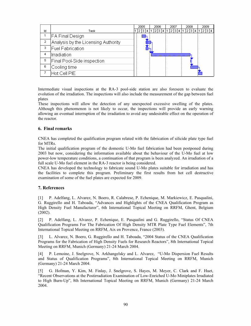
90
Intermediate visual inspections at the RA-3 pool-side station are also foreseen to evaluate the evolution of the irradiation. The inspections will also include the measurement of the gap between fuel plates These inspections will allow the detection of any unexpected excessive swelling of the plates. Although this phenomenon is not likely to occur, the inspections will provide an early warning allowing an eventual interruption of the irradiation to avoid any undesirable effect on the operation of the reactor. 6. Final remarks CNEA has completed the qualification program related with the fabrication of silicide plate type fuel for MTRs. The initial qualification program of the domestic U-Mo fuel fabrication had been postponed during 2003 but now, considering the information available about the behaviour of the U-Mo fuel at low power-low temperature conditions, a continuation of that program is been analyzed. An irradiation of a full scale U-Mo fuel element in the RA-3 reactor is being considered. CNEA has developed the technology to fabricate sound U-Mo plates suitable for irradiation and has the facilities to complete this program. Preliminary the first results from hot cell destructive examination of some of the fuel plates are expected for 2009. 7. References [1] P. Adelfang, L. Alvarez, N. Boero, R. Calabrese, P. Echenique, M. Markiewicz, E. Pasqualini, G. Ruggirello and H. Taboada, “Advances and Highlights of the CNEA Qualification Program as High Density Fuel Manufacturer”, 6th International Topical Meeting on RRFM, Ghent, Belgium (2002).
[2] P. Adelfang, L. Alvarez, P. Echenique, E. Pasqualini and G. Ruggirello, “Status Of CNEA Qualification Programs For The Fabrication Of High Density MTR Plate Type Fuel Elements”, 7th International Topical Meeting on RRFM, Aix en Provence, France (2003).
[3] L. Alvarez, N. Boero, G. Ruggirello and H. Taboada, “2004 Status of the CNEA Qualification Programs for the Fabrication of High Density Fuels for Research Reactors”, 8th International Topical Meeting on RRFM, Munich (Germany) 21-24 March 2004.
[4] P. Lemoine, J. Snelgrove, N. Arkhangelsky and L. Alvarez, “U-Mo Dispersion Fuel Results and Status of Qualification Programs”, 8th International Topical Meeting on RRFM, Munich (Germany) 21-24 March 2004.
[5] G. Hofman, Y. Kim, M. Finlay, J. Snelgrove, S. Hayes, M. Meyer, C. Clark and F. Huet, “Recent Observations at the Postirradiation Examination of Low-Enriched U-Mo Miniplates Irradiated to High Burn-Up”, 8th International Topical Meeting on RRFM, Munich (Germany) 21-24 March 2004.

91
[6] M. Mirandou, M. Granovsky, M. Ortiz, S. Balart, S. Aricó and L. Gribaudo, “Reaction layer between U-7wt%Mo and Al alloys in chemical diffusion couples”. 2004 International Topical Meeting on Reduced Enrichment for Research and Test Reactors, Vienna, Austria, November 7-12, 2004.
[7] R. Calabrese, “High Density Fuel Program in RA-3”, U-Mo Fuel Qualification Workshop, Argonne National Laboratory, January 17-18, 2000. 7. Acknowledgments We deeply recognize the collaboration and permanent support of J. Snelgrove, G. Hofman and T. Wienceck from Argonne National Laboratory.

92
POST IRRADIATION EXAMINATIONS ON UMO FULL SIZED PLATES
- IRIS2 EXPERIMENT -
F. HUET, J. NOIROT, V. MARELLE, S. DUBOIS
CEA - Cadarache 13 108 - Saint-Paul-lez-Durance Cedex, France
P. BOULCOURT, P. SACRISTAN, S. NAURY, P. LEMOINE
CEA - Saclay 91 191- Gif-sur-Yvette Cedex, France
ABSTRACT IRIS2 irradiation was the last irradiation of 4 full sized plates launched by CEA for the French UMo group to test in which operating conditions the coarse porosity forms in the UMo/Al interaction product. IRIS2 consists in four plates with high uranium loading and U-7wt%Mo atomised powder irradiated up to 60 days at OSIRIS reactor in IRIS device at a peak power of 238 W.cm-2. The results show that in the tested conditions pillowing of the plate started from a fission density over 2 1021 fission.cm-3. Moreover, they show that the fission products and impurities have a key–role in the origin of the excessive plate swelling.
1. Introduction The French UMo Group program has been launched by 1999 in close collaboration with five partners : CEA, CERCA, COGEMA, FRAMATOME-ANP AND TECHNICATOME[1]. The initial goal of this program was to contribute to the high performances and reprocessable UMo fuel international development (RERTR). To reach this goal the French Group chose to irradiate full-sized experimental plates with low enriched uranium and high uranium loading up to 8 g.cm-3. As a first step of this program, IRIS1 irradiation established the good behaviour of high uranium loading UMo plates, for heat flux up to 140 W.cm-2 (~3.4 1014 f.cm-3
UMo.s-1), 67% BU (~4.6 1021 f.cm-
3UMo) with a cladding surface temperature below 75°C[2]. However, as an other step, FUTURE
irradiation pointed out fuel performance limitations for higher irradiation flux, i.e. 340 W.cm-2 [3](~6.3 1014 f. cm-3
UMo.s-1). Indeed this experiment indicated that a porosity can form and coarse in the U-Mo/Al interaction phase. This porosity leads to excessive swelling (pillowing) of the plates. This result was confirmed by others international programs[4]. In order to assess the irradiation limits for which the coarsening porosity forms in the UMo/Al interaction, IRIS2 experiment was initiated in OSIRIS reactor IRIS device. Peak heat flux and cladding wall temperature were 238 W.cm-2 and 93°C. The results show that for these operating conditions coarse porosity and pillowing of the plates have also occurred from fission density over 2.1021fission.cm-3
UMo. The aim of this paper is to present IRIS2 experiment results. 2. IRIS 2 as fabricated plates For IRIS2 experiment, four experimental plates with high uranium loading (8.3 gU.cm-3) were fabricated by CERCA. The fuel plates consists of U-7wt%Mo atomised fuel powder dispersed in aluminium matrix. The cladding material is AG3-NE. The main characteristics of the as-fabricated plate meat are summarized in Table 1 : U-7wt%Mo loading is around 51vol% and the porosity lower than 2%.
93
Plate ref. Thickness
(mm) U-7wt%Mo
(vol%) Al
(vol%) Porosity (vol%)
P#02 51.5 47.0 1.5 P#03 51.4 46.9 1.6 P#07 51.6 47.0 1.4 P#08
0.51
51.7 47.2 1.1
Table 1 : IRIS2 fuel plates meat main characteristics 3. Irradiation 3.1 Irradiation history The four plates were irradiated in OSIRIS reactor IRIS irradiation test rig[5]. The IRIS device is associated to an in-pool plate thickness measurements device. It enables to assess plate thickness profiles at each reactor cycle stop. Peak irradiation heat flux and cladding temperature of the four plates are given Table 2.
Heat flux (W.cm-2) Cladding surface temperature (°C)
Cycle n° FPD P #02 P#03 P#08 P#07 P #02 P#03 P#08 P#07 1 15.1 238 217 214 231 93 89 89 92 2 13.2 237 216 213 229 93 89 88 91 3 12.0 213 201 / 225 88 87 / 91 4 17.6 212 206 / / 88 87 / /
Table 2 : Maximum Flux Plane (MFP) peak irradiation conditions( Full Power Day)
The plate P#08 was removed after the second cycle, due to a slight warping of it during intercycle handling. The irradiation of the three other plates was further stop before reaching the 50% target burnup. Indeed, for safety reason the swelling admissible limit for the plate is 250 µm and this limit was reached at the end of the third cycle for P#07 and at the fourth cycle for the 2 other plates (P#02 and P#03): 3.2 In-pool plate thickness measurements IRIS 2 plate thickness swelling is given Figure 1 as a function of the fission density. As a comparison IRIS 1[2] and FUTURE[3] experiments swelling are also plotted. The results show that for IRIS2 irradiation conditions, plate pillowing occurs from around 2 1021 fission.cm-3
UMo. These results are consistent with FUTURE experiment one. For lower irradiation conditions and grounded particles (IRIS1 experiment), no pillowing was observed up to 4.8 1021 fission.cm-3
UMo.
0
2
4
6
8
10
12
14
16
18
20
0.E+00 1.E+21 2.E+21 3.E+21 4.E+21 5.E+21
Fission density (fission/cm3)
Plat
e sw
ellin
g (%
)
IRIS2 - P#02 IRIS1 [2]
IRIS2 - P#03 FUTURE [3]
IRIS2 - P#07
Figure 1 : Plate swelling versus fission density (fission.cm-3
UMo).

94
4. Post-Irradiation Examinations (PIE) A large set of PIE was performed on the most deformed plate, i.e. P#02 at the maximum flux plane. The sample is chosen in order to have the edge of the plate meat together with the large pillowing area. Burnup at this location evolves from 2.8 1021 to 2.9 1021 fission.cm-3
UMo and at the peak temperature in
the meat is 112°C[6]. 4.1 Metallographic examinations Metallographs of the sample, shown Figure 2, indicate a microstructure similar to FUTURE [3] experiment one. They confirm that the origin of the plate pillowing is coarse porosity at the (U-Mo)-Al interaction product interface with aluminium. All the stages of the porosity formation and coarsening are seen, from no porosity area (Figure 2a) to a big hole at the plate pillowing location (Figure 2d). In the pillowing area, it can be seen indications of interaction product plastic deformation but no signs of U-7wt%Mo alloy microstructure evolution.
a) b) c) d)
Figure 2 : Metallographic examinations on IRIS2 Plate P#02 at MFP 4.2 EPMA X-ray mappings at the different locations identified in Figure 2 are presented Figure 4. The mappings underline :

95
A depletion of molybdenum content observed at the U-Mo alloy grain boundaries. It has
already been observed in past experiment with atomised powders[7], A fission product accumulation at the interface between interaction product and aluminium
matrix. However, for solid fission product, as for example Zr, no evolution of their concentration is visible, while at contrary for Xe, this accumulation disappears as the porosity increases, i.e. from location -a to - d of Figure 4.
Quantitative analyses were also done. They indicate that the aluminium content of the interaction layer decreases continuously from "U-MoAl6" to "U-MoAl4.5", respectively from edge of the meat (Figure 4-a) to the pillowing area (Figure 4-d). 4.3 SEM examinations
a/ b/ c/ Figure 3 : SEM images of Plate P#02 meat.
SEM examinations presented Figure 3 show :
fission gas bubble precipitation at the grain boundaries of UMo alloy particles, where the Mo content is lower (-b & -c),
no fission gas bubbles are observed in the "U-MoAl" interaction layer (-a, -b & -c), when 2 UMo particles are close together, some link, like sintering link are observed in
between the particles, larger fission gas bubbles are observed in the linking compound (-c). the UMo particles interface with UMoAl interaction product is not smooth, it could
indicate that interaction occurs at preferential location, as grain boundaries (-b & -c), dark lines are visible at the interfaces where two interaction layer meet together (-b).
5. Discussion The results obtained indicate that, during irradiation, as the temperature increases, the aluminium content in interaction compound decreases from "(U-Mo)Al6" at the coldest to "(U-Mo)Al4.5" at hottest position of IRIS2 sample. These results are consistent with previous experiments. Indeed, for IRIS 1[2] low temperature experiment, "(U-Mo)Al7" compound has been found while for higher temperature experiment[3]
(FUTURE) it was (U-Mo)Al3-4". The origin of the large pores development in the interaction product is still not clear, but from the results it seems that the fission products have a key-role in it. Indeed, it seems that while the interaction layer grows, the fission products (FP) and impurities (of aluminium matrix) are "pushed" at its periphery (see dark interaction borders Figure 3-b). One explanation of that could be a low solubilization of the FP in the interaction product. Then the reaction is stopped at some weak location, at the interaction product / aluminium interface when the amount of FP and impurities is high enough. It could be the porosity formation beginning. Moreover, when porosity started to form, gases could progressively fill it by diffusion process. This phenomenon is enhanced by the local temperature
AlUMo
UMoUMo
Interaction product
Pore

96
increase due to the low conductivity of the so-formed porosity. This process is irreversible and spiral out of control and leads to porosity coarsening. On the other hand, IRIS2 experiment indicates a good behaviour with temperature of the U-7wt% Mo alloy itself. Indeed, even at rather high temperature (pillowing area) no indications of excessive FG release or bubble growth are observed in the fuel particles. 6. References [1] J.M. Hamy et al, "Status of March 2003 of the UMo development program", Proceedings of the 7th
International Meeting on RRFM, Aix en Provence, France, 9-12 march 2003. [2] F. Huet et al, "Full sized plates irradiation with high UMo fuel loading – IRIS1 experiment final
results", Proceedings of the 25th International Meeting on RERTR, Chicago, Il., USA, 5-10 October 2003.
[3] A. Leenaers et al, "Post-irradiation examinations of U-7wt%Mo atomized dispersion fuel", JNM, 335, (2004), 39-47.
[4] G.L. Hofman et al, "Recent observation at the PIE of low enriched UMo miniplates irradiated to high burnup". Proceedings of the 8th International Meeting on RRFM, Munich, Germany, 21-24 March 2003.
[5] P. Sacristan et al, "MTR fuel plate qualification in OSIRIS reactor", Proceedings of the 26th International Meeting on RERTR, Vienna, Austria, 7-12 November 2004.
[6] V. Marelle et al, "Mechanical calculations on U-Mo dispersion fuel plates with MAIA", these proceedings.
[7] Ki Hwan Kim et al "Thermal compatibility of centrifugally atomised U-Mo powders with aluminium in dispersion fuel", Nuclear Engineering and Design, 178, 1997, 111-117.
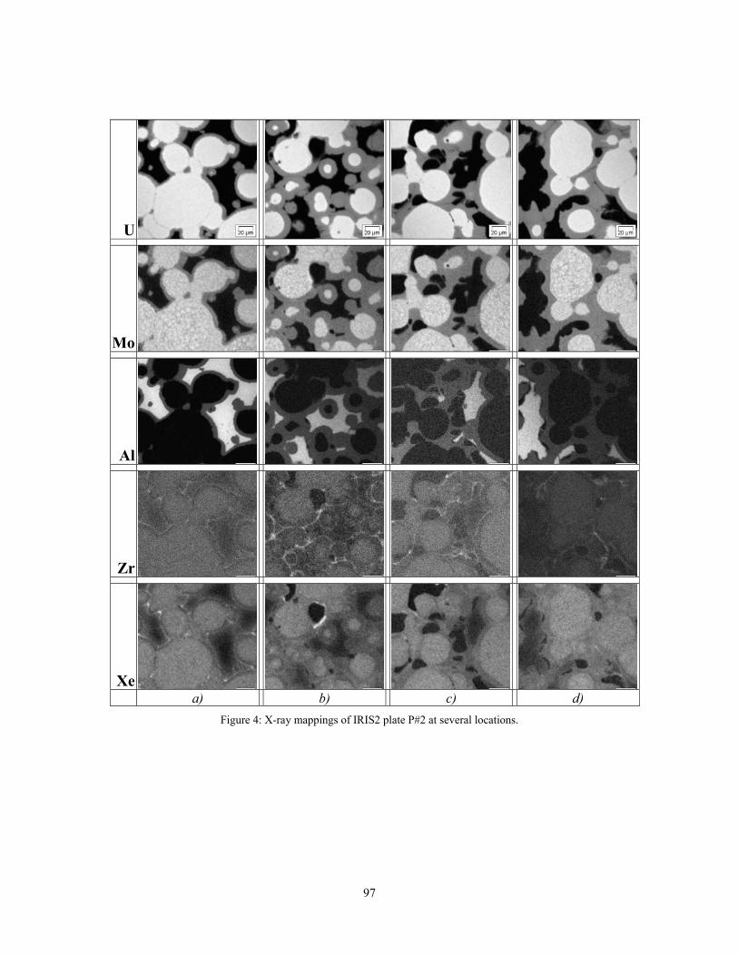
97
U
Mo
Al
Zr
Xe
a) b) c) d) Figure 4: X-ray mappings of IRIS2 plate P#2 at several locations.

98
MECHANICAL CALCULATIONS ON U-Mo DISPERSION FUEL PLATES WITH MAIA
V. MARELLE and F. HUET CEA – Cadarache
F-13108 Saint-Paul-Lez-Durance Cedex, France
and
P. LEMOINE CEA – Saclay
F-91191 Gif-sur-Yvette Cedex, France
ABSTRACT CEA has developed a 2D thermo-mechanical code, called MAIA, for modelling the behaviour of U-Mo dispersion fuel. MAIA uses a finite element method for the resolution of the thermal and mechanical problems. Physical models, issued of the DOE-ANL code PLATE, evaluate the fission products swelling and the volume fraction of the interaction between U-Mo and Al. They allow establishing strains in the meat imposed as loading for the mechanical calculation. MAIA has been validated on the irradiations IRIS 1 and RERTR-3 and a rather good agreement is obtained with post irradiation examinations. MAIA is used to calculate the last irradiation of the French UMo group, IRIS 2. MAIA predicts a maximum temperature of 112°C and meat swelling of 16%. Mechanical calculations are finally performed to evaluate the sensitivity to some mechanical hypotheses such as constitutive laws and the way the meat swelling is applied.
1. Introduction MAIA is a 2D thermo-mechanical code used for modelling the behaviour of U-Mo dispersion fuel plates. The meat is treated as a homogeneous material for the thermal and mechanical resolution with a Finite Element Method (FEM). The evolution of the meat composition is calculated throughout the irradiation taking into account the fading of as-fabricated porosities, the swelling due to fission products and the interaction between the U-Mo particles and the Al matrix. A model also evaluates the cladding oxidation. 2. MAIA Code evolutions Several improvements have been made on MAIA since the last version of the code presented during RRFM 2004 [1]. A Contact ratio is now used to limit the increase of the interaction compound when the matrix volume fraction become lower and a shape factor on particles is applied to correctly evaluate the volume of the interaction compound for non-spherical particles. These evolutions are issued from PLATE, the code developed by the DOE-ANL [2]. Many improvements on the mechanical calculations have also been made to get more consistent results with more modelling options.

99
3. Validation MAIA has first been qualified on analytical test cases to make sure of the good behaviour of the code. Then MAIA has been validated on the available irradiation data: IRIS 1 [3] and RERTR-3 [4]. The Post Irradiation Examinations (PIE) have been compared with MAIA results on the interaction layer thickness and the volume fractions. A rather good agreement is obtained (cf. Figure 5). A benchmark with PLATE has also been carried out in order to make sure of the consistency of the results and to identify improvements in the modelling that were necessary.
Figure 5: MAIA/PIE comparison on interaction layer thickness (1a) and volume fractions (1b)
4. IRIS 2 results MAIA has been used to calculate the plate P#02 of the IRIS 2 irradiation (four cycles) [5]. Calculation has been made in the Maximum Flux Plane (MFP). The different results presented in this paper are in the middle of this plane where the flux is locally the highest. The maximum temperature in the meat calculated by MAIA is 112°C (cf. Figure 6). The external plate temperature in the middle of the MFP decreases from 94°C at beginning of life to 79°C at end of life.
Figure 6: Temperatures in the middle of the plate at the MFP
Interaction layer thickness
0
2
4
6
8
10
12
14
0 2 4 6 8 10 12 14Measured (μm)
Cal
cula
ted
(μm
)
Volume fractions
0
10
20
30
40
50
60
0 10 20 30 40 50 60Measured (%)
Cal
cula
ted
(%)
U-Mo Aluminium Interaction
3040
506070
8090
100
110120
0 5E+26 1E+27 1.5E+27 2E+27 2.5E+27 3E+27
Fission density (fissions/m3 of U-Mo)
Tem
pera
ture
(°C
)
Centre Meat-Cladding Boehmite-Cladding Ext plate Coolant
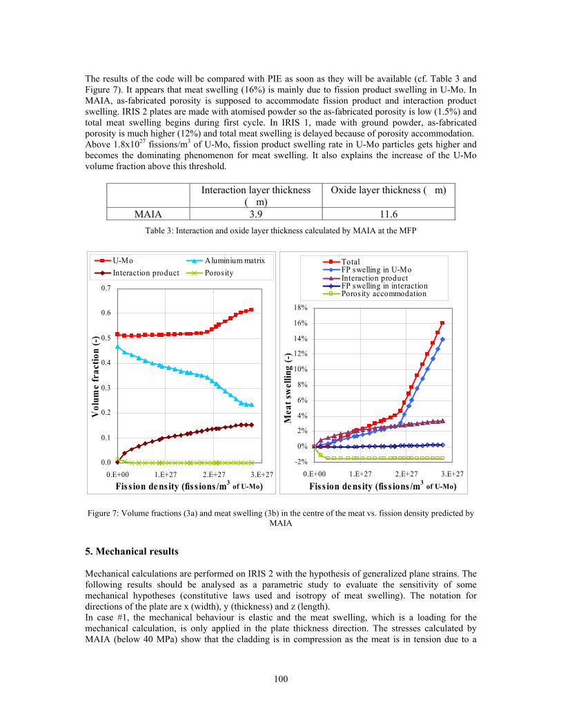
100
The results of the code will be compared with PIE as soon as they will be available (cf. Table 3 and Figure 7). It appears that meat swelling (16%) is mainly due to fission product swelling in U-Mo. In MAIA, as-fabricated porosity is supposed to accommodate fission product and interaction product swelling. IRIS 2 plates are made with atomised powder so the as-fabricated porosity is low (1.5%) and total meat swelling begins during first cycle. In IRIS 1, made with ground powder, as-fabricated porosity is much higher (12%) and total meat swelling is delayed because of porosity accommodation. Above 1.8x1027 fissions/m3 of U-Mo, fission product swelling rate in U-Mo particles gets higher and becomes the dominating phenomenon for meat swelling. It also explains the increase of the U-Mo volume fraction above this threshold.
Interaction layer thickness (�m)
Oxide layer thickness (�m)
MAIA 3.9 11.6 Table 3: Interaction and oxide layer thickness calculated by MAIA at the MFP
Figure 7: Volume fractions (3a) and meat swelling (3b) in the centre of the meat vs. fission density predicted by
MAIA
5. Mechanical results Mechanical calculations are performed on IRIS 2 with the hypothesis of generalized plane strains. The following results should be analysed as a parametric study to evaluate the sensitivity of some mechanical hypotheses (constitutive laws used and isotropy of meat swelling). The notation for directions of the plate are x (width), y (thickness) and z (length). In case #1, the mechanical behaviour is elastic and the meat swelling, which is a loading for the mechanical calculation, is only applied in the plate thickness direction. The stresses calculated by MAIA (below 40 MPa) show that the cladding is in compression as the meat is in tension due to a
0.0
0.1
0.2
0.3
0.4
0.5
0.6
0.7
0.E+00 1.E+27 2.E+27 3.E+27Fiss ion dens ity (fiss ions /m3 of U-Mo)
Vol
ume
frac
tion
(-)
U-Mo Aluminium matrixInteraction product Porosity
-2%
0%
2%
4%
6%
8%
10%
12%
14%
16%
18%
0.E+00 1.E+27 2.E+27 3.E+27
Fiss ion density (fiss ions /m3 of U-Mo)
Mea
t sw
ellin
g (-
)
TotalFP swelling in U-MoInteraction productFP swelling in interactionPoros ity accommodation

101
higher thermal expansion coefficient of the cladding (cf. Figure 8). The meat swelling doesn’t generate any significant evolutions on the stresses in the middle of the plate. In case #2, the constitutive laws used are elasto-viscoplasticity for cladding and plasticity for meat. The meat swelling is still only applied in the plate thickness. The main differences with the previous results are stress relaxation and a sign change of the stresses during inter-cycles (cf. Figure 9). Case #3 is like case #2 but with isotropic meat swelling. It gives very different results (cf. Figure 10). After the beginning of meat swelling, meat is in compression and cladding in tension. The stresses reached in the meat are much higher that in the previous cases (the yield stress is reached in the meat). In the cladding, because of the creep, the stress remains below 50 MPa. The highest values are reached during the stops of the reactor.
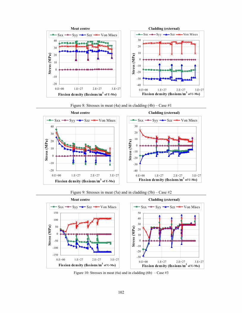
102
Meat centre Cladding (external)
Figure 8: Stresses in meat (4a) and in cladding (4b) – Case #1
Meat centre Cladding (external)
Figure 9: Stresses in meat (5a) and in cladding (5b) – Case #2
Meat centre Cladding (external)
Figure 10: Stresses in meat (6a) and in cladding (6b) – Case #3
-40
-30
-20
-10
0
10
20
30
0.E+00 1.E+27 2.E+27 3.E+27Fiss ion de ns ity (fiss ions/m3 of U-Mo)
Stre
ss (M
Pa)
Sxx Syy Szz Von Mises
-20
-10
0
10
20
30
40
0.E+00 1.E+27 2.E+27 3.E+27
Fiss ion dens ity (fis s ions/m3 of U-Mo)
Stre
ss (M
Pa)
Sxx Syy Szz Von Mises
-40
-30
-20
-10
0
10
20
30
0.E+00 1.E+27 2.E+27 3.E+27Fiss ion density (fis s ions/m3 of U-Mo)
Stre
ss (M
Pa)
Sxx Syy Szz Von Mises
-20
-10
0
10
20
30
40
0.E+00 1.E+27 2.E+27 3.E+27
Fiss ion density (fiss ions /m3 of U-Mo)
Stre
ss (M
Pa)
Sxx Syy Szz Von Mises
-30
-20
-10
0
10
20
30
40
50
0.E+00 1.E+27 2.E+27 3.E+27Fiss ion de ns ity (fis s ions/m3 of U-Mo)
Stre
ss (M
Pa)
Sxx Syy Szz Von Mises
-150
-100
-50
0
50
100
150
0.E+00 1.E+27 2.E+27 3.E+27
Fiss ion de ns ity (fiss ions /m3 of U-Mo)
Stre
ss (M
Pa)
Sxx Syy Szz Von Mises
103
Plate thickness increase is similar for cases #1 and #2 (cf. Figure 11): viscoplastic strains are much lower than meat swelling. For IRIS 1, this increase is close to the value given by PIE. For IRIS 2, PIE cannot be compared straight with MAIA results because of the large porosities that appeared in this part of the plate and which are not modelled in MAIA. In case #3, the plate thickness decreases because of the high strains in the width and the length of the cladding. This hypothesis does not seem very realistic.
Figure 11: Plate thickness increase
6. Conclusion MAIA can now be considered as a consistent code for U-Mo dispersion fuel plates thanks to its validation base. It can also be used for mechanical calculations. MAIA is therefore a useful tool to analyse and explain the behaviour of the U-Mo dispersion fuel plates. Nevertheless the mechanical hypotheses have to be studied further to fix the best options for a realistic modelling. The meat swelling for instance should be mainly applied in the plate thickness. The mechanical characterizations that are in progress will also improve the modelling through a better knowledge on the material properties of the meat and the cladding. 7. References [1] V. Marelle, F. Huet, P. Lemoine, “Thermo-mechanical modelling of U-Mo fuels with MAIA”, 8th International Topical Meeting on Research Reactor Fuel Management, München, Germany, March 21-24, 2004, pp164-168
[2] S.L. Hayes, G.L. Hofman, M.K. Meyer, J. Rest, J.L. Snelgrove, “Modeling of high density UMo dispersion fuel plate performance”, 2002 International meeting on Reduced Enrichment for Research and Test Reactor, San Carlos de Bariloche, Argentina, November 3-8, 2002
[3] F. Huet, V. Marelle, J. Noirot, P. Sacristan, P. Lemoine, “Full-sized plates irradiation with high-UMo fuel loading – Final results of IRIS 1 experiment”, 2003 International meeting on Reduced Enrichment for Research and Test Reactor, Chicago, Illinois, USA, October 5-10, 2003, pp151-163
[4] M.K. Meyer, G.L. Hofman, R.V. Strain, C.R. Clark, J.R. Stuart, “Metallographic analysis of irradiated RERTR-3 fuel test specimens”, 2000 International meeting on Reduced Enrichment for Research and Test Reactor, Las Vegas, Nevada, USA, October 1-6, 2000
[5] F. Huet, J. Noirot, V. Marelle, S. Dubois, P. Boulcourt, P. Sacristan, P. Lemoine, “Post-irradiation examinations on U-Mo full sized plates – IRIS 2 experiment”
-40-20
020406080
100120
IRIS 1 IRIS 2Plat
e th
ickn
ess
incr
ease
(μm
)
Case #1Case #2Case #3PIE
104
OUT OF PILE FRENCH RESEARCH PROGRAM ON THE UMo/Al SYSTEM: FIRST RESULTS
S. DUBOIS, F. MAZAUDIER,
J.P. PIRON, P. MARTIN, J.C. DUMAS, F. HUET CEA-Cadarache, DEN/DEC, 13108 St Paul lez Durance – Cedex – France
H. NOËL, O. TOUGAIT Université de Rennes1. CNRS-UMR6511 - Av. du Général Leclerc - 35042 Rennes – Cedex – France
C. JAROUSSE CERCA – les Bérauds - BP 1114 - 26104 Romans – Cedex – France
P. LEMOINE CEA-Saclay – 91191 Gif sur Yvette – Cedex – France
ABSTRACT This paper focuses on a French scientific program built to gain further knowledge on the UMo/Al interaction and to discuss promising solutions to prevent this interaction under neutron flux. Three themes are thus developed. Thermodynamic investigations, through U-Mo-Al ternary system studies, may lead to determining the phase equilibria at different temperatures. Metallurgical out-of-pile diffusion couple studies are intended to improve the understanding of diffusion mechanisms and should underline the role of different parameters, which could prevent or decrease the UMo/Al reaction. Finally, the irradiation effect has been taken into account, either through a simulation program or an in-pile one. The results already achieved are described and discussed.
1. Introduction Recent in-pile experiments have shown that dispersed UMo fuel in a pure Al matrix does not withstand high operating conditions [1], [2], [3]. Extensive porosity is formed in the reaction layer, at the fuel/matrix interface, resulting in an unacceptable pillowing and/or swelling of the fuel plate. The behaviour of this interaction seems to be responsible, directly or indirectly, for such a limit. Out-of-pile experiments have shown similar phenomena: UMo/Al interaction [4, 5] and, at times, a large amount of porosities [6]. The out of pile mechanisms, which are probably different from the in-pile ones, have to be considered in order to understand the UMo/Al system and then select solutions to prevent (or at least limit) this fuel/matrix interaction. To this end, a French extended program has been carried out by the CEA, with a specific collaboration with CERCA, for the manufacturing aspects. This paper presents this program and the first results. 2. French research program on the UMo/Al system In order to gain further knowledge on the UMo behaviour, and to propose solutions to its operating limit, the French scientific program is divided into three following closely linked themes. 2.1. Phase diagram studies

105
Thermodynamic studies with the determination of the phase equilibria within the U-Mo-Al ternary system are the basis of our program. These studies are performed within the framework of a collaboration with Rennes University. Up to now, phase relations in the U-Mo-Al ternary system have not been fully determined. Previous investigations were limited to the partial isothermal sections at 500°C, 1050°C and 1250°C for the composition range U-Mo-Mo3Al8-UAl2 [7]. The main reported feature is the formation of a rather extended homogeneous region with a cubic UAl2-xMox structure, corresponding to the substitution of Al by Mo in the binary aluminide UAl2, up to x = 0.66. It changes into a hexagonal phase at the higher substitution ratio. Two ternary compounds were subsequently discovered in the aluminium rich part of the system: UMo2Al20 which crystallizes in the cubic structure type CeCr2Al20 (space group Fd3m) [8], and U6Mo4Al43 with crystallizes with the hexagonal Ho6Mo4Al43 structure type (space group P63/mcm) [9]. In order to obtain more information on phase equilibria, we have started a program to determine isothermal sections of the U-Mo-Al phase diagram at 400°C and 800°C. The first results are presented in § 3. This experimental part will be completed with thermochemistry calculations. These will be performed as a function of the temperature, with the SAGE (Solgasmix Advanced Gibbs Energy) code, in order to compare the stability of the ternary compounds which might form at the UMo/Al interface. The mathematical treatment is based on the minimisation of the Gibbs free energy. However, the input data, i.e. the thermodynamic functions of the components, are mostly unknown. The first step thus consists in calorimetric measurements on previously selected and well characterised phases in the U-Mo-Al system. 2.2. Metallurgical studies In addition, metallurgical studies take into account the diffusion phenomenon, in relation with the material features (grain size, crystallography, defects, chemical homogeneity…). Thus, compatibility tests are intended to understand the influence of the different key parameters and select promising solutions (see § 4). Among the main parameters, we study the influence of cristallography (α or γ phase), the microstructure (grain size…), the Mo content and its distribution. Means for UMo/Al fuel improvement will be investigated, such as additive precipitates (Si), where a delaying effect on interdiffusion is expected. The materials were investigated using classical techniques: optical and scanning electron microscopy, energy dispersive analysis (EDAX), and X-ray diffraction (XRD) techniques. Furthermore, more specific techniques will be used. As interaction layers between the UMo and Al matrix might be heterogeneous [5, 10], micro-XRD characterisation will be performed, in order to identify the crystallographic phases. Besides, to determine the local environment of uranium and molybdenum elements, micro-XAS studies also appear to be well suited, even in case of poorly crystallized or amorphous materials. Both investigations require intense X-Ray beams and will be performed at the ESRF (European Synchrotron Radiation Facilities). 2.3. Influence of irradiation The two previous parts of the program are necessary to improve the understanding of the UMo/Al interaction phenomenon. They may lead to select additives or other alternative solutions. However, the promising solutions have to meet the manufacturing process requirements and behave well under irradiating (irradiation damage, neutronic, thermal and mechanical issues). To consolidate the out of pile program, we first intend to use high energy ion irradiation, typically 70 MeV Xenon (or Ag), in order to simulate (the most) damage created by fission products. These experiments will be carried out on both interdiffusion layers and fuel plates. The consequences of simulated irradiation on fuel/matrix interaction kinetics will be characterized by micro-XRD and micro-XAS as described previously.

106
At last, in-pile irradiation (see §5) will then be discussed and performed to determine fuel behaviour and to validate the pertinence of the chosen solution. 3. Phase diagram studies of the U-Mo-Al system 3.1. Experimental procedure For each isothermal section, about forty samples were prepared; their composition is presented (as filled squares) in Fig.1. High purity metals, uranium pieces (99.8 wt. %), molybdenum chips (99.99 wt %) and aluminium rods (99.999 wt %) were arc-melted in a water-cooled copper-hearth under an atmosphere of purified argon.
Fig 1. Studied compositions in the U-Mo-Al system.
0.0 0.2 0.4 0.6 0.8 1.0
0.0
0.2
0.4
0.6
0.8
1.0 0.0
0.2
0.4
0.6
0.8
1.0
(<735°C)(<731°C) Mo4Al17
(U-10Mo)
(MoAl12) (<700°C)
MoAl5
Mo3Al
Mo3Al8UAl3
UAl4
AlU
Mo
U Mo
Al
UAl2
(U2Mo)
(U-7Mo)
1220
6443
The buttons were melted at least three times (weight losses < 1%) to ensure a proper homogeneity. A part of each as-cast alloys was annealed either at 400°C or 800°C for one to two months and for two weeks to one month respectively. After the heat-treatment, the samples were quenched in air. Samples taken from the as-cast and heat-treated buttons were ground and polished. Each average composition was characterized by optical microscopy, SEM analyses and X-ray powder diffraction. 3.2. First results 3.2.1. Binary and pseudo-binary UAlx phases UAl4 has been confirmed to be a stoechiometric compound, as previously reported [11] and does not dissolves any amount of molybdenum. The solubility of Mo in UAl3 is also very slight, and limited to a maximum of 1-2 at.%. Moreover, our results confirm that Mo has a large solubility in UAl2. The solid solution UAl2-xMox (MgCu2-type cubic structure) extends up to x = 0.5 both at T= 400°C and 800°C. But this study also confirms the formation, for higher Mo substitution, of a hexagonal phase with the MgZn2-structure type. Microprobe analysis indicate that this latter phase is stabilized within the limits 0.70<x<0.85 at T = 400°C and 0.6<x<0.7 at T = 800°C. However, it is not sure that full equilibrium was achieved at 400°C, even after two months of annealing. Consequently, the substitution of Mo atoms to Al sites in the ternary extension of binary phases leads to U(Al2-xMox) type notation, rather than (U,Mo)Al2 commonly written in many papers, which is misleading concerning atomic site occupation. 3.2.2. UMo2Al20 and U6Mo4Al43 compounds The preparation of ternary alloys with the stoechiometric compositions UMo2Al20 and U6Mo4Al43 systematically led to three phase mixtures. Both microprobe and X-ray powder diffraction analysis revealed non-stoechiometric phases showing large homogeneity ranges. U6Mo4Al43 is characterized by a positive deviation of the Mo content, whereas UMo2Al20 shows a positive deviation of Al content. Similar deviations from stoechiometry were also found in the analogous rare earth-based phases, like Ho6Mo4+xAl43-x [8] or CeMo2-xAl20+x [9] and can be thus considered as a prominent feature of these structural types. Crystal structure refinements of U6Mo4+xAl43-x and UMo2-xAl20+x are being carried out using single crystal X-ray diffraction data, in order to more accurately determine crystallographic site occupations and to obtain further knowledge on the Mo/Al substitution process. Our phase diagram studies clearly reveal the lines: UAl4-UMo2-xAl20+x at 400°C, and UAl3-UMo2-xAl20+x at 800 °C ; thus UMo2-xAl20+x is directly formed as a result of the interaction between the
107
U-7Mo fuel and aluminium powder. The analytical data reported recently [10] for the “Al-rich (Al,U,Mo) phase” compares perfectly with the atomic composition of this ternary phase. 4. Metallurgical studies 4.1. Experimental procedure The materials employed were aluminium (1050A, 99.5%) or aluminium alloy (e.g. 6061 with Si content) and arc-melted U–Mo alloys manufactured within the range of Mo content (0 to 10 wt.%). Part of the as-cast U-Mo alloys were heat treated at 900°C for 72 hrs to achieve a good homogenisation and then quenched (cooling rate > 2000°C/h) at room temperature, in order to retain the high temperature γ- phase. The samples underwent a thermal treatment to modify both structure and microstructure and then evaluate their influence on interdiffusion layer. Heat treatments from 400°C to 600°C were performed in a high purity Ar atmosphere, under a controlled pressure (1-10 MPa), for several hours. These temperatures were chosen in order to be the upper and lower limits around the eutectoid temperature (565°C). Above 565°C, a metastable γ-phase decomposition is observed. Chemical diffusion couples were tightly mechanically maintained using a specific device during the whole thermal treatment. 4.2. First results 4.2.1 Mo content and structure effect The Mo content must be sufficient (above 5 wt. % in UMo) to stabilize the metastable γ-UMo phase. The global and the local Mo concentrations are therefore both key parameters. Especially, Mo depleted areas may increase the interdiffusion and interaction zones. Since Mo is nearly insoluble in α-U, the intermetallics UAlx are thermodynamically more stable. As expected, the Mo content is of major importance to stabilize the γ-phase and thus modify the U/Al reaction kinetic. An irregular interface is a constant feature of the as-cast alloy based samples (Fig 2.a). Such irregularities have been observed in [5]. Some of the interfacial areas did not react at all, probably due to local surface phenomena such as impurities or local strain variation. 4.2.2 Microstructure effect In the case of a formerly heat treated UMo alloy, the thicknesses of the interaction layer are rather smaller, and even nil (Fig 2.c). The annealing at 900°C delays the decomposition of the metastable γ-phase, at a temperature in the range of 400-600°C. Actually, the former heat treatment results in two main changes in the UMo alloy:
- a microstructural one, with grains coarsening from ~ 20 µm to 400-1000 µm. Consequently, the grain boundary density decreases inversely, and thus limits the diffusion paths and amount of defects,
- a chemical one, with a better Mo distribution. The Mo homogenisation prevents local low Mo content which enhances the decomposition process of the γ phase and the UMo/Al interaction.
The interest of homogenisation has already been observed, on either U–7wt%Mo/Al diffusion couple [5] or dispersed atomized U-10 wt% Mo alloy particles [4]. The former homogeneity directly affects the type, morphology and interdiffusion layer growth. 4.2.3 Silicon effect In the 6061 aluminium alloy, the Si content amounts to 0.4-0.8 wt. %. Its presence significantly reduces the interaction thickness (Fig 2.b and Fig 2.d). Our first results are in agreement with previous experiments on UAl/Al, which have proven that a small amount of silicon in the Al matrix prevented UAl4 formation, stabilized UAl3 and reduced the diffusion rate at the UAl/Al interface [12, 13]. Recent studies [14] have not shown any change in the
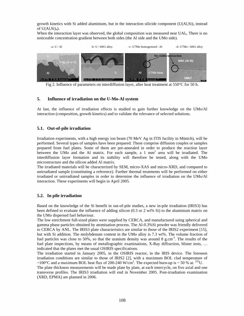
108
growth kinetics with Si added aluminium, but in the interaction silicide component (U(Al,Si)3 instead of U(Al,Si)4). When the interaction layer was observed, the global composition was measured near UAl3. There is no noticeable concentration gradient between both sides (the Al side and the UMo side).
-a- U / Al -b- U / 6061 alloy -c- U7Mo homogenised / Al -d- U7Mo / 6061 alloy
Fig 2. Influence of parameters on interdiffusion layer, after heat treatment at 550°C for 50 h.
5. Influence of irradiation on the U-Mo-Al system At last, the influence of irradiation effects is studied to gain further knowledge on the UMo/Al interaction (composition, growth kinetics) and to validate the relevance of selected solutions. 5.1. Out-of-pile irradiation Irradiation experiments, with a high energy ion beam (70 MeV Ag in ITIS facility in Münich), will be performed. Several types of samples have been prepared. These comprise diffusion couples or samples prepared from fuel plates. Some of them are pre-annealed in order to produce the reaction layer between the UMo and the Al matrix. For each sample, a 1 mm2 area will be irradiated. The interdiffusion layer formation and its stability will therefore be tested, along with the UMo microstructure and the silicon added Al matrix. The irradiated materials will be characterized by SEM, micro-XAS and micro-XRD, and compared to unirradiated sample (constituting a reference). Further thermal treatments will be performed on either irradiated or unirradiated samples in order to determine the influence of irradiation on the UMo/Al interaction. These experiments will begin in April 2005. 5.2. In pile irradiation Based on the knowledge of the Si benefit in out-of-pile studies, a new in-pile irradiation (IRIS3) has been defined to evaluate the influence of adding silicon (0.3 or 2 wt% Si) to the aluminium matrix on the UMo dispersed fuel behaviour. The low enrichment full-sized plates were supplied by CERCA, and manufactured using spherical and gamma phase particles obtained by atomisation process. The Al-0.3%Si powder was friendly delivered to CERCA by ANL. The IRIS3 plate characteristics are similar to those of the IRIS2 experiment [15], but with Si addition. The molybdenum content in the UMo alloy is 7.3 wt%. The volume fraction of fuel particles was close to 50%, so that the uranium density was around 8 g.cm-3. The results of the fuel plate inspections, by means of metallographic examinations, X-Ray diffraction, blister tests, … indicated that the plates met the usual OSIRIS specifications. The irradiation started in January 2005, in the OSIRIS reactor, in the IRIS device. The foreseen irradiation conditions are similar to those of IRIS2 [2], with a maximum BOL clad temperature of ~100°C and a maximum BOL heat flux of 200-240 W/cm2. The expected burn-up is ~ 50 % at. 235U. The plate thickness measurements will be made plate by plate, at each intercycle, on five axial and one transverse profiles. The IRIS3 irradiation will end in November 2005. Post-irradiation examination (XRD, EPMA) are planned in 2006.
U
UAlx (3<x<5)
Al U Al U7Mo hom.
No visible interaction
109
6. Conclusion This paper focuses on a French extended research program on dispersed UMo fuel. An experimental determination of the U-Mo-Al phase diagram is in progress. The results reveal that the two previously reported ternary phases U6Mo4+xAl43-x and UMo2-xAl20+x are non-stoechiometric, with significant homogeneity ranges. Up to 25% of Al can be substituted by Mo in UAl2 all the while keeping the cubic MgCu2-type structure, and a hexagonal MgZn2-type UAl2-xMox pseudo-ternary phase is stabilized for higher Mo contents. The Mo solubility is nil in UAl4 and very low in UAl3. Thermodynamical calculations will be further performed. Couple diffusion studies are intended to improve our understanding of the phenomena and to select promising alternative solutions to UMo/Al problem. The first results underline the sensitivity of the UMo/Al interaction to, at least, the following parameters: Mo content, homogenisation, microstructure, structure and additives. As an ultimate validation, irradiations have to be performed. High energy ion irradiation experiments are foreseen. Besides, 4 full-sized UMo LEU plate irradiation (IRIS3) is ongoing in OSIRIS. This experiment will test the effect of silicon added to aluminium matrix.

110
7. References [1] G. L. Hofman, M. R. Finlay, Y.S. Kim, International Meeting on Reduced Enrichment for Research and Test Reactors (RERTR), Vienna, Austria, 7-12 November 2004. [2] P. Lemoine, J.L. Snelgrove, N. Arkhangelsky, L. Alvarez, 8th International Topical Meeting on Research Reactor Fuel Management (RRFM), München, Germany, March 21-24, 2004. [3] A. Leenaers, S. Van den Berghe, E. Koonen, C. Jarousse, F. Huet, M. trotabas, M. Boyard, S. Guillot, L. Sannen, M. Verwerft, J. Nucl. Mater. 335 (2004) 39-47. [4] J.S. Lee, C.H Lee, K.H. Kim, V. Em, J. Nucl. Mat. 306 (2002) 147–152. [5] M.I. Mirandou, S.N. Balart, M. Ortiz, M.S. Granovsky, J. Nucl. Mat. 323 (2003) 29–35. [6] K.H. Kim, D.B. Lee, C.K. Kim, G.L. Hofman, K.W. Paik, Nucl. Eng. Design, 178 (1997) 111-117. [7] G. Petzow, J. Rexer, Z. Metallkd. 62 (1971) 34-38. [8] S. Niemann, W. Jeitschko, Journal of Solid State Chemistry 114, (1995) 337-341. [9] S. Niemann, W. Jeitschko, Z. Metallkd. 85 (1994) 5, p. 345-349. [10] D.D. Keiser, C.R. Clark, M.K. Meyer, Scripta Materialia 51 (2004) 893–898. [11] O. Tougait, H. Noël, Intermetallics 12 (2004) 219-223. [12] W.C. Thruber, R.J. Beaver, ORNL-2602 report, Oak Ridge National Laboratory, 1959. [13] A.K. Chakraborty, R.S. Crouse, W.R. Martin ORNL-TM-2800 report, Oak Ridge National Laboratory, 1970. [14] M. Mirandou, M. Granovsky, M. Ortiz, S. Balart, S. Arico, L. Gribaudo, International Meeting on Reduced Enrichment for Research and Test Reactors (RERTR), Vienna, Austria 7-12 November 2004. [15] F. Huet, J. Noirot, V. Marelle, P. Boulcourt, P. Sacristan, P. Lemoine, this conference.

111
QUALIFICATION of HIGH DENSITY ALUMINIDE FUELS FOR THE BR2 REACTOR
André BEECKMANS de WEST-MEERBEECK Pol GUBEL
Bernard PONSARD SCK•CEN, BR2 reactor
Boeretang 200, 2400 Mol, Belgium
Thomas PIN AREVA / CERCA
ZI Les Bérauds, 26104 Romans, France
Jean Louis FALGOUX AREVA / CERCA
Tour FRAMATOME, 92084 Paris La Défense, France
ABSTRACT The BR2 operation still relies on the use of 90..93% enriched HEU aluminide fuel. The availability of a limited batch of 73% enriched HEU from reprocessed BR2 uranium in Dounreay justified 10 years ago the qualification and use of this material. After some preliminary test irradiations, various batches of fuel elements were fabricated by the UKAEA-Dounreay and successfully irradiated. Due to their lower 235U content (0.050 g 235U/cm²), these elements were always irradiated together with standard 90...93% HEU fuel elements. A mixed-core strategy was developed at this occasion for an optimal utilization, and was reported during the 4th RRFM conference (March 19-21, 2000, Colmar, France). The availability of a new batch of fresh 73% HEU material was the occasion, a few years ago, to initiate the development, fabrication and qualification of a new high density fuel element. An order was placed with CERCA to assess the optimal fabrication methods and tooling required to meet as far as possible the existing BR2 standard specifications and 235U content (0.060 g 235U/cm²). This development phase has been already reported during the 7th RRFM conference (March 9-12, 2003, Aix-en-Provence, France). Afterwards, six lead test fuel elements were ordered for qualification by irradiation. The neutronic properties of the fuel elements were adjusted and optimized. After a short summary of the main results of the development program, this paper describes the nuclear characteristics of the high density fuel elements and comments on the nuclear follow-up of the lead test fuel elements during their irradiation for five cycles in the BR2 reactor and the return of experience for CERCA.
1. Introduction [1] At the request of the SCK●CEN’s BR2 reactor, CERCA developed in 2002 a fuel element using high density plates with a 73% U235 enriched aluminide alloy instead of the standard 93% U235 enriched. The purpose of this development was mainly to maintain the U235 content per unit area at its 60 mg/cm2 nominal value while keeping the same technical specifications for fabrication. Due to the tolerances on enrichment, U content per plate, core thickness and others, the U content had to be increased from ~ 64,5 mg/cm2 to a maximum of 86 mg/cm2 (+ 33 %).
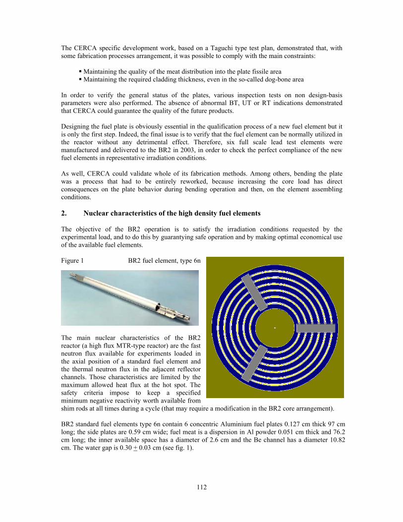
112
The CERCA specific development work, based on a Taguchi type test plan, demonstrated that, with some fabrication processes arrangement, it was possible to comply with the main constraints:
Maintaining the quality of the meat distribution into the plate fissile area Maintaining the required cladding thickness, even in the so-called dog-bone area
In order to verify the general status of the plates, various inspection tests on non design-basis parameters were also performed. The absence of abnormal BT, UT or RT indications demonstrated that CERCA could guarantee the quality of the future products. Designing the fuel plate is obviously essential in the qualification process of a new fuel element but it is only the first step. Indeed, the final issue is to verify that the fuel element can be normally utilized in the reactor without any detrimental effect. Therefore, six full scale lead test elements were manufactured and delivered to the BR2 in 2003, in order to check the perfect compliance of the new fuel elements in representative irradiation conditions. As well, CERCA could validate whole of its fabrication methods. Among others, bending the plate was a process that had to be entirely reworked, because increasing the core load has direct consequences on the plate behavior during bending operation and then, on the element assembling conditions. 2. Nuclear characteristics of the high density fuel elements The objective of the BR2 operation is to satisfy the irradiation conditions requested by the experimental load, and to do this by guarantying safe operation and by making optimal economical use of the available fuel elements. Figure 1 BR2 fuel element, type 6n
The main nuclear characteristics of the BR2 reactor (a high flux MTR-type reactor) are the fast neutron flux available for experiments loaded in the axial position of a standard fuel element and the thermal neutron flux in the adjacent reflector channels. Those characteristics are limited by the maximum allowed heat flux at the hot spot. The safety criteria impose to keep a specified minimum negative reactivity worth available from shim rods at all times during a cycle (that may require a modification in the BR2 core arrangement). BR2 standard fuel elements type 6n contain 6 concentric Aluminium fuel plates 0.127 cm thick 97 cm long; the side plates are 0.59 cm wide; fuel meat is a dispersion in Al powder 0.051 cm thick and 76.2 cm long; the inner available space has a diameter of 2.6 cm and the Be channel has a diameter 10.82 cm. The water gap is 0.30 + 0.03 cm (see fig. 1).

113
Figure 2. Configuration 20G The BR2 core configuration (fig. 2) reflects that all criteria are satisfied, e.g. the configuration 20G contains 34 fuel elements, 6 shim rods, 3 PWR loops, a flux trap in the central channel H1 and reflectors channels used for the regulating rod and for the production of radio-isotopes, most of them committed for the production of 99Mo. The economical use of the fuel cycle is determined by the energy produced by a fuel element till it reaches the burn-up value at elimination. The residual fuel mass has been observed to be about 200 g 235U in an external channel during the last operation cycle. Routinely high reactive fuel at the 2nd batch are loaded in the central ring (channels A and B) and 6 to 8 fresh fuel are located in the second ring (channels C and D) in such a way the energy produced reaches at least 1200 MWd/cycle. Repeating the reactivity calculation in an unitary cell as in previous communications [2,3,4], the adjoint of thermal neutron flux is the general shape of a configuration when the BR2 core contains an homogeneous fuel loading. The perturbation theory applied on the system: Φ=Φ FB .. λ gives the variation of the eigenvalue � and the perturbed solution: Φ+Φ=Φ δ' ; the variation of the eigenvalue is obtained with the bilinear product by weighting the neutron importance:
>ΦΦ<
>Φ−Φ<=−= +
+
''
'
.)..('
FFB δλδλλδλ and Φ−−=Φ− ))(()( ''' FBFB λδδδλ
The comparison of the new fuel type "F" with the standard fuel type "G" and with other fuel compositions makes the main answer for the reactivity performance: reactivity when fresh, maximum reactivity and burn-up at elimination. At the figure 3, the reactivity versus the equivalent burn-up for energy produced (taking into account the Pu production) shows the fuel element type "F" containing 400 g 235U enriched at 72.5% has the same reactivity curve as the standard BR2 fuel element type "G" containing 400 g 235U enriched at 72.5% meanwhile a modification in the content of burnable poisons. The number of fuel elements to produce 1000 MWd remains 6.2 elements permitting to maintain the routine schedule of BR2 operations. At a burn-up at elimination: 50%, the reactivity loss is calculated negligible: 0.006 $ x 34 el. = 0.20 $ for a whole configuration at the end of a cycle.

114
Table 1. Fuel Composition of BR2 Fuel Elements
Figure 3. Calculated reactivity variation in unitary BR2 cell for various type of fuel elements
reactivity [$] variation in unitary BR2 fuel cell
-0.4
-0.3
-0.2
-0.1
0
0.1
0.2
0.3
0.4
0.5
0.6
0 0.05 0.1 0.15 0.2 0.25 0.3 0.35 0.4 0.45 0.5
burnup equivalent for energy produced
G_400A_244C_330E_330F_400W_400
3. Experience gained with the irradiation of the lead test fuel elements [5] The six test fuel elements were irradiated in the same circumstances that standard BR2 fuel elements are used. They were loaded firstly in the 2nd ring (channel C) when fresh and then in the central ring (channels A and B) and finally they were pushed at high burn-up rate successfully.
type 6 n G A C E F W unit
HEU 0.9 0.93 0.9 0.725 0.725 0.725 [-]
U-235 400.0 244.0 330.0 330.0 400.0 400.0 [g] U-236 0 0 0 54.5 0 0 [g] U-238 40.0 17.1 33.0 36.3 110.0 110.0 [g] Sm2O3 1.4 - 1.3 1.3 1.4 - [g Sm.nat]
B4C 3.8 - 2.8 1.8 3.2 - [g B.nat] Cd diameter - - - - 0.06 36*cm
density 0.060 0.037 0.050 0.050 0.060 0.060 g-235U/cm2
1.310 0.774 1.081 1.342 1.627 1.627 g-U/cm3
�.mean 0.50 0.24 0.39 0.39 0.50 0.50 [-] � .max 0.62 0.32 0.50 0.50 0.62 0.62 [-]
max fission density 1.60 0.50 1.07 1.07 1.60 1.60 1e+21/cm3 number of batch 4 2 3 3 4 4 [-]
utilization 6.2 21.2 9.5 9.5 6.2 6.2 element/GWd
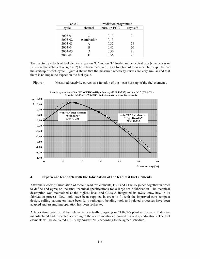
115
Table 2. Irradiation programme cycle channel burn-up EOC days.eff
2003-01 C 0.13 21 2003-02 examination 0.13 2003-03 A 0.32 28 2003-04 B 0.42 20 2004-05 D 0.50 21 2005-01 F 0.56 21
The reactivity effects of fuel elements type 6n "G" and 6n "F" loaded in the central ring (channels A or B, where the statistical weight is 2) have been measured – as a function of their mean burn-up – before the start-up of each cycle. Figure 4 shows that the measured reactivity curves are very similar and that there is no impact to expect on the fuel cycle.
Figure 4 Measured reactivity curves as a function of the mean burn-up of the fuel elements.
-1,40
-1,20
-1,00
-0,80
-0,60
-0,40
-0,20
0,00
0,20
0,40
0,60
0,80
0 10 20 30 40 50 60
Mean burnup [%]
Δρ
[$]
○ 6n "F" fuel element"High Density"
72% U-235
• 6n "G" fuel element"Standard"93% U-235
Reactivity curves of 6n "F" (CERCA-High Density-72% U-235) and 6n "G" (CERCA-Standard-93% U-235) BR2 fuel elements in A or B channels
4. Experience feedback with the fabrication of the lead test fuel elements After the successful irradiation of these 6 lead test elements, BR2 and CERCA joined together in order to define and agree on the final technical specifications for a large scale fabrication. The technical description was maintained at the highest level and CERCA integrated its R&D know-how in its fabrication process. New tools have been supplied in order to fit with the improved core compact design, rolling parameters have been fully rethought, bending tools and related processes have been adapted and assembling operation has been rechecked. A fabrication order of 30 fuel elements is actually on-going in CERCA's plant in Romans. Plates are manufactured and inspected according to the above mentioned procedures and specifications. The fuel elements will be delivered in BR2 by August 2005 according to the agreed schedule.

116
The first industrial inspection results are conforming to the expectation. As an example the obtained cladding thickness (fig. 5) and U distribution (fig. 6) are as below:
Fig. 5a Core center area Fig. 5b Dog bone area
Fig. 6. Plate U distribution 5. Conclusions CERCA proposed to develop, manufacture and deliver to the BR2 reactor a new design of fuel element based on a 73%
235
U
enriched aluminide alloy as an alternative to the standard HEU element (93%
235
U
enriched). The development challenge was to maintain the fuel element performances as high as possible while keeping the present acceptance criteria for the fabrication process. The results of the development program demonstrated it was possible to switch to the lower enriched alloy while maintaining the total amount of
235
U into the core. Consequently, six full scale lead test elements were manufactured, delivered to the BR2, and irradiated for five cycles, reaching a final burn-up of more than 55%. The nuclear characteristics were chosen by design to meet those of standard HEU elements (93%
235
U
enriched). The follow-up of these elements during their irradiation demonstrated that they completely met the requested performances and nuclear characteristics. Final technical specifications were agreed between CERCA and SCK•CEN for a large scale fabrication taking account of the experience gained with the fabrication and irradiation of the six lead test fuel elements. A first batch of 30 elements is now under fabrication and should be delivered to the reactor site during the summer 2005. A second similar batch is foreseen for delivery in 2006. The experience learned that the allocation of the necessary resources of a fabricator (CERCA) and an operator (BR2) was necessary to conduct successfully a development project in a timely manner.

117
6. References [1] Th. PIN, Y. LAVASTRE, J.L. FALGOUX, P. GUBEL, F. JOPPEN: "Manufacturing of Uranium
High Density Fuel Elements using Uranium 73% 235U enriched, in an Aluminide Alloy for the BR2 Reactor", 7th RRFM-2003 meeting held in Aix-en-Provence, March 9-12, 2003.
[2] A.BEECKMANS: "Fuel requirements for experimental devices in MTR reactors - A perturbation model for reactor core analysis" presented at the 13th RERTR Meeting held in Berlin on 10-13 Sept 1989 published in den Konferenzen des Forschungszentrums Jülich Band 4/1991, and GEX-R-163.
[3] A. BEECKMANS, E. KOONEN: "A Preliminary study on the suitability of high density LEU fuel
elements to maintain BR2 operational characteristics", 6th RRFM-2002 meeting held in Ghent on March 17-20, 2002.
[4] A. BEECKMANS: "The use of Cadmium Wires as Burnable Poison - A First Feasibility Study
for the BR2 Reactor", 8th RRFM-2004 meeting held in München on March 21-24, 2004. [5] B.PONSARD: "Mixed Core Management : Use of 93% and 72% enriched uranium in the BR2
Reactor ", 4th RRFM-2000 meeting held in Colmar (France), March 19-21, 2000.

118
STATUS REPORT ON THE NUCLEAR START-UP OF FRM-II
K. SCHRECKENBACH and H. GERSTENBERG ZWE FRM-II, TU München 85747 Garching, Germany
ABSTRACT The new research reactor FRM-II in Garching became critical for he first time on March 2nd, 2004. In the following start-up procedure the thermal power was increased stepwise for a large test program in safety and performance including secondary sources and experi-mental facilities. The nominal power was reached in August 2004 and the end of the first full cycle in October 2004. The result of this successful start-up procedure is reported here.
1. Introduction The ‘Forschungs-Neutronenquelle Heinz-Maier Leibnitz’ (FRM-II) is a high flux neutron beam reactor which is optimized on a high thermal neutron flux ( 8·1014 n/cm2s without in-pile installations) at a relatively low nominal power of 20 MW. The reactor core is light water cooled and surrounded by a heavy water filled tank serving as moderator and reflector. The compact fuel element of highly enriched uranium is designed for a cycle length of 52 days. The production of thermal, cold, hot and fission neutrons serves for basic research in neutron physics and for applied science and technology. The FRM-II was designed in the eighties and construction started finally in 1996 in a cooperation of Siemens as general contractor and the TU München. The FRM-II passed a severe commission procedure over several years. Finally the facility was allowed for the start-up and produced the first neutrons in March 2004. The program included also special in-pile sources such as cold source, hot source, positron source, converter source, silicon doping facility and irradiation facilities. A thermal power of 5 MW was reached in May 2004 and the nominal power was reached for the first time in August 2005. The first reactor cycle ended in October 2005 followed by a visual inspection of the fuel element. The program and the results of this first reactor cycle are reported here. 2. Concept of the FRM-II In Fig 1 the basic lay-out of the FRM-II in the moderator tank area is shown. The fuel element is placed in the central channel of the moderator tank. The uranium zone is 700 mm in height; the diameter of the compact core is only 243 mm. The fuel element is cooled by light water with a flow of 300 l/s. The water is heated by about 15°C. The heat is transferred via heat exchangers to a secondary cooling circuit and then to cooling towers. The mean power density in the core at 20 MW is about 1 MW/l. In the centre of the fuel element the control rod of Hafnium can be moved from the top. At the bottom position of the control rod the reactor is well undercritical. An arrangement of five shut down rods is moved back for normal reactor operation and is dropped into the moderator tank for a fast shut-down. These shutdown rods act on about 25% of neutrons in the chain reaction which are reflected from the moderator tank back to the fuel. The thermal neutron flux maximum is at a distance of about 12 cm from the surface of the central channel and thus accessible by beam tubes to extract thermal neutrons to the experimental areas. For the first nuclear start-up, a Cf-252 neutron source was placed in a vertical channel of the moderator tank. Six neutron detectors surround the moderator tank for monitoring the power via the neutron flux. Furthermore three gamma detectors measure the N-16 activity in the primary cooling circuit as a relative measure for the reactor power averaged over the core.

119
Fig.1 Concept of the FRM-II facility
3. Investigations at low reactor power The counting rates of three of those neutron detectors during the first criticality approach are shown in Fig. 2. Before placing the fuel element in the channel the counting rates of the neutron detectors were recorded and compared with MNCP calculations. Relative to these numbers the expected counting rate for the fuel element and the reactor in operation at a given power were calculated. Knowing the absolute neutron activity of the Cf-252 source the absolute counting rates as function of the reactor power could be predicted and were put as a calibration factor in the reactor control system. With the control rod and shut down rods at the bottom the detected neutrons are coming mainly from the Cf-252 source and show with the above calibration the non-cylindrical symmetry (Fig.2). When lifting the shut-down rods and then the control rod, the neutron multiplication of the fuel element increases and the neutron emission geometry gets close to the cylindrical fuel geometry. After criticality the reactor was stabilized at a power of 1 kW. As later calibration of the power proved, the knowledge of the absolute reactor power was already precise to about 10 %. The position of the control rod at criticality was found at 70 mm below mid core and agreed to MCNP calculations within a few mm. Further power calibrations were achieved via neutron flux measurements in a vertical beam tube in comparison with the prediction of MCNP calculations. At 150 kW a further check of the reactor power was performed by measuring the temperature rise of the primary cooling water under adiabatic conditions (cooling towers shut off), a method which is independent of the speed of the cooling flow. Several important numbers for the reactivity of the reactor core were measured by a reactimeter. The reactivity change by a step wise change of the rod position was measured and thus the efficiency calibration of the control rod and the shut down rods determined. Furthermore the negative temperature coefficient of the reactor core was verified by changing the temperature of the primary cooling circuit and measuring the change of the control rod position for a constant reactor power. The change in reactivity by moving irradiation samples or the converter plate is of the order of 10 pcm (10·10-5). The change of the reactivity between cold source filled with liquid D2 and with gaseous D2 was measured as 245 pcm.

120
Fig.2 Calibrated counting rate in three neutron detectors during the first criticality.
As final step of the low power investigations the reactor was run for two days at 50 kW. Then the core was moved to the storage pool and gamma lines of the produced fission products were measured by an under water apparatus shown in Fig.3. The spatial resolution of this gamma scan was 6 mm in height and 13 mm in width. By this method the power distribution in the core could be measured. A comparison with MCNP calculations (Fig.3) shows an excellent agreement also in respect to the influence of the cold source on the cylindrical symmetry.
Fig.3 Comparison of measured and calculated azimuthal power density distribution at different heights in the fuel element. Before the measurement the fuel element was operating at 50 kW for two days. A section of the outer ring (thickness 13 mm) is viewed by the collimator. The dip due to the cold source
is clearly visible (arrow)

121
4. Investigations at higher reactor power up to the nominal value After the gamma scan measurements the fuel element was placed again in the central channel und the reactor power was increased stepwise. For each of the seven power steps a number of investigations were performed, recorded and evaluated. Altogether about 250 separate investigations were performed. Various systems were investigated at different power of the reactor: cooling systems, power control, test scrams, radiology, temperature, etc.. A large test program was also established for the in-pile sources. The temperature control of the cold source was optimized and its neutron spectrum was measured at an external neutron beam (Fig. 4). For the hot source the temperature in the middle of the source was recorded by a noise thermometer to 2090 °C at nominal power. The flux distribution in the silicon doping facility was measured and without any liner the variation of the thermal neutron flux in the 500 mm long silicon sample was only between 1.52 to 1.69·1013 n/cm2s. The short term stability in reactor power was measured via the neutron intensity at a neutron beam and showed a stability within a few permille (Fig. 5). In order to keep the mean power independent of the control rod position during a cycle the control level for the neutron counters is automatically calibrated to the N-16 detectors.
Fig.4 Neutron spectrum recorded by time of flight at the exit of a beam tube, which views the cold source.
Fig.5 Stability of the reactor power measured via a neutron counter at the exit of a beam tube. The counts were recorded in intervals of one second (rate about 15 000 cts/s)

122
After these tests the remaining fuel capacity was used for two continuous runs of together 28 days at nominal power providing neutrons for the scientific instruments. After the operation of the reactor with the first fuel element corresponding to 52 days nominal power the reactor was shut down. From the position and efficiency of the control rod a prolongation of a cycle by about 8 days of nominal power would be possible but needs a formal application. As the final step of the nuclear start-up program the fuel element was removed from the central channel and visually inspected under water showing a perfect surface. 5. Preparation for the routine operation of the FRM-II The many documents of the start-up procedures were arranged and comprehensive reports were written. Following the experience of the start-up procedure some technical improvements in radiological shielding, neutron beam tubes and neutron sources are undertaken. Also the results and the experience of the first reactor cycle were included in the manuals and repeating examination procedures. Finally the FRM-II facility has to be taken over by the TU München from the general contractor Siemens and a permission for the routine operation has to be obtained from the regulatory authority. It is envisaged to start the routine operation of the FRM-II with the second fuel element and a 52 day run at full power in spring 2005.

123
REDUCED ENRICHMENT PROGRAM FOR THE FRM-II, STATUS 2004/05
A. Röhrmoser, W. Petry, N. Wieschalla Zentrale Wissenschaftliche Einrichtung FRM-II,
Technische Universität München, D-85747 Garching bei München, Germany
ABSTRACT
With the nuclear license for the new research reactor FRM-II, that was granted in May 2003, a condition was imposed to reduce the enrichment of FRM-II from highly enriched uranium (HEU) to medium enriched uranium (MEU) with not more than 50% until the end of the year 2010. The TUM has established an international working group to meet this target. The planning is split into three periods 2½ year each. This paper presents the progress achieved up to now and an actualized planning for the coming irradiation tests.
1. FRM-II, concept sketch The new research reactor FRM-II represents a high performance neutron source at the moderate thermal power of 20MW. The requirements for a large volume of high neutron flux accessible for experiments have been met with a compact fuel element with maximal uranium density of 3.0 g/cm3 of highly enriched uranium (HEU, 93% U-235). An outline of the fuel element’s position is shown in Fig. 1.
Fig. 1. Horizontal cut 20 cm below the core mid plane of FRM-II (extract of original geometry used in 3d-calculations). One can recognize the inner part of the D2O-moderator tank with the H2O cooled fuel element in the central position. The control rod together with the Be-follower (green) moves in the inner space of the fuel element. The 5 shutdown rods are shown in their shutdown position surrounding the fuel element very tight with a safety margin of 1 cm. One further recognizes in this cut the nose of the horizontal beam tubes SR-7 and SR-8 as well as the closest part of the hot source HQ. The important cold source in FRM-II is remarkably closer to the element than the HQ but not present at 20 cm below the core mid plane.

124
The single fuel element design, that was presented early 1988 [1], went into operation 1½ decades later in March 2004. The first fuel element cycle was finished successfully when reaching the designed 52 full power days in Oct. 2004. Routine operation of the FRM-II starts beginning 2005. 2. Reduced enrichment for FRM-II, background and actual schedule First enrichment studies for a new FRM were performed by TUM during the design phase in the 80’ies. The maximum uranium density with the fuel U3Si2 was assumed to be not higher than 4.8 g/cm3. In comparison to a LEU variant the FRM-II HEU element achieved a maximum flux level that was 35% higher [2]. In 1995/96, nearly one decade after the final TUM design of the element and at beginning of the construction phase for FRM-II there were presented alternative designs for FRM-II by the RERTR group at Argonne [3]. It was shown that a conversion to LEU was impossible without severe geometry changes even with unrealistic uranium metal densities of 19 g/cm3. In 1998 the new “red-green”-Federal Government expressed its wish to take the FRM-II into operation with a fuel element with reduced enrichment – so far the scientific aims are met. In 2001 an ‘Agreement between the Federal Republic of Germany and the Free State of Bavaria on the conversion of FRM-II’ has been written down and finally signed after granting the final license in May 2003. This compromise is part of the final nuclear license and aims for the development of a new medium enriched (MEU, not more than 50 % U-235) fuel element until the end of the year 2010 [4]. In Nov. 2001 TUM has established an international working group to study the possibility of a new fuel with up to now not qualified densities and reduced enrichment. The group consisted of representatives of the TUM (FRM-II), the fuel element manufacturer CERCA and the constructor of FRM-II, Framatome-ANP (former Siemens-KWU). With start of the kick-off meeting in July 2003 (the French CEA joined later that year) the group declared to accept the technological challenge of the development of a MEU fuel element for FRM-II within the very short time limit of 7½ years. The project was broken down into three phases of 2½ years duration each:
I. search for the fuel type, test irradiations II. further test irradiations, final decision on the fuel type and design of the fuel
element III. fabrication of the fuel element and licensing
3. MEU conversion FRM-II, Phase I In program Phase I the high density fuel shall be chosen or at least done a preselection. This first 2½ years phase spreads from 7.2003 till 12.2005 and the following tasks are assigned to Phase I:
a) calculations for the high density fuel(s) for FRM-II geometry b) irradiations of MEU full size fuel plates c) participation in international research programs
3.1 Calculations with high density fuels Any scenario to convert the FRM-II has to keep the reactor power constant at 20 MW, to guaranty a duration of the fuel cycle of 52 days and to yield, if at all, only marginal losses in the neutron flux and quality. Without changing the whole D2O moderator tank with all its installations and its shutdown rods the core geometry must remain unchanged. This is
125
necessary not only to avoid a complete new licensing procedure but also a reactor shutdown period of many years and costs of more than 150 million Euros as stated by a sharp estimation. For an enrichment of 50% an advanced fuel with high density is required when maintaining the dimensions of the HEU compact core fuel element of the FRM-II.
UMo-Al dispersive fuel
The new uranium-molybdenum dispersion fuel (UMo-Al) presently is under research worldwide up to 8.5 g/cm3. TUM did actual neutronics calculations for this fuel with the same procedures that led to the HEU design of FRM-II (criticality, burn up …). The result was now that the density in the fuel must be at least 7.75 g/cm3 with an enrichment of 50% U-235. When taking into account other aspects like the less fortunate power density distribution with UMo, the minium density can hardly be below 8.0 g/cm3. The core contains then 10.8 kg U-235 instead of 7.5 in the actual HEU case. The total U mass is 21.6 kg instead of 8.0 kg now. The production of Pu increases from 11g (actual design) to 70g. One key point is the radial power form factor, which is a description of the radial dependency of the heat load of the coolant channels (axial flow) in the fuel element. Fig.2 shows the calculated form factors in FRM-II at BOL for the currently used U3Si2-Al HEU fuel, for UMo-Al dispersive MEU fuel of U-density 8g/cm3 and the comparison of the two cases. It becomes evident that the form factor with the MEU fuel is less opportune than in the current case. Particularly the maximum of the heat load in the outer zone is much higher than actually and can not be accepted for a final design. Efforts must be made to flatten the power distribution; f. i. one could further reduce the density in the outer region what in the countermove will reduce criticality. Another key point is the maximum of the fission density (FD) in the fuel. Because of the very inhomogeneous power and fission density in the plates maxima are reached only in very small areas of the plate. This is different from irradiation tests, where the plates are much more homogeneously irradiated. The relevant maximum of the value in FRM-II must be assigned to the inner part of the plate. The result of these preliminary calculations is that the maximum of fission density in the meat is up to 2.0.1021 cm-3 in a narrow area at the inner and outer border of the high density region. Test irradiations have to show what fission densities the new fuel can withstand under conditions as in FRM-II. Still the thermal flux is depressed by about 8.0% when compared to the actual HEU fuel, i.e. the aim of only marginal consequences for the scientific use is not yet met.
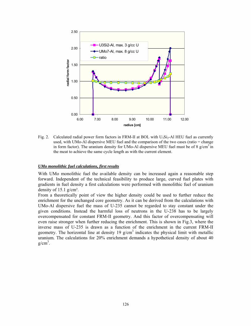
126
0.00
0.50
1.00
1.50
2.00
2.50
6.00 7.00 8.00 9.00 10.00 11.00 12.00radius [cm]
radi
al fo
rm fa
ctor
U3Si2-Al, max. 3 g/cc UUMo7-Al, max. 8 g/cc Uratio
Fig. 2. Calculated radial power form factors in FRM-II at BOL with U3Si2-Al HEU fuel as currently
used, with UMo-Al dispersive MEU fuel and the comparison of the two cases (ratio = change in form factor). The uranium density for UMo-Al dispersive MEU fuel must be of 8 g/cm3 in the meat to achieve the same cycle length as with the current element.
UMo monolithic fuel calculations, first results
With UMo monolithic fuel the available density can be increased again a reasonable step forward. Independent of the technical feasibility to produce large, curved fuel plates with gradients in fuel density a first calculations were performed with monolithic fuel of uranium density of 15.1 g/cm³. From a theoretically point of view the higher density could be used to further reduce the enrichment for the unchanged core geometry. As it can be derived from the calculations with UMo-Al dispersive fuel the mass of U-235 cannot be regarded to stay constant under the given conditions. Instead the harmful loss of neutrons in the U-238 has to be largely overcompensated for constant FRM-II geometry. And this factor of overcompensating will even raise stronger when further reducing the enrichment. This is shown in Fig.3, where the inverse mass of U-235 is drawn as a function of the enrichment in the current FRM-II geometry. The horizontal line at density 19 g/cm3 indicates the physical limit with metallic uranium. The calculations for 20% enrichment demands a hypothetical density of about 40 g/cm3.

127
0
0,02
0,04
0,06
0,08
0,1
0,12
0,14
0,16
0% 20% 40% 60% 80% 100%enrichment
inve
rse
U m
ass
[1/k
g]
0,00
5,00
10,00
15,00
20,00
25,00
30,00
35,00
40,00
45,00
dens
ity [g
/cc]
mass U-235mass U totalU densityU metal density
Fig. 3. Inverse mass of U-235 and U-total (respectively the corresponding U density, right scale)
necessary in FRM-II to obtain a cycle length of 52 days. In the calculations particular enrichments have been chosen (see dots) and the uranium density has been treated as a variable.
In the case of 34% enrichment, which corresponds to the density of UMo monolithic fuel the loss in thermal neutron flux will be clearly more than 10%. The mass of uranium in the fuel element would be above 40 kg instead of 8 kg now, thus five times higher. The mass of U-235 would be in the order of 14 kg instead of 7.5 kg now, thus nearly doubled. The production of Pu per fuel cycle increases to 110g. The radial form factor shows even higher peaks than in Fig.2 and further density gradients have to be introduced. A fuel element of that kind still burns not more 1.3 kg U-235, i.e. only 9.6% of U-235 would be used. The high density of UMo monolithic fuel opens new possibilities in the search for a compromise between the contradicting demands of decreasing enrichment and highest scientific quality of a neutron source. For the given FRM-II geometry this could mean a better burn up ratio or in other words longing for a longer cycle length for FRM-II, to compensate the penalty of a lower flux value in the order of 8% in the case of 50% enrichment. A raise in the power level is more difficult to achieve because of the less opportune power distribution in the reduced enrichment case.
3.2 Irradiation program
For Phase I it was decided to plan an irradiation of four test plates of full size. For this purpose six plates are already produced by CERCA with UMo-Al dispersive fuel (8% wt. Mo). The uranium densities are 8g/cm3 for 4 plates and 7g/cm3 for the two other plates. For all plates the Mo concentration in the UMo alloy has been increased from originally 7wt.% to 8wt.%. This measure intends to stabilize the γ-Phase, which in turn is mandatory to accumulate the fission products in a proper way. Two of the 8g/cm3 plates contain the additive of a possible considerable “diffusion blocker”. It is expected that these diffusion blockers suppress the formation of the Al rich AlUMo phase. The formation of that latter phase is regarded as the cause for the break away swelling observed in recent irradiations of UMo-Al dispersive fuel plates [5]. We used 2% of silicon additive in the Al matrix (cmp. [6]).
128
Including an margin to cover uncertainties a FD of 2.3.1021.cm-3 (compare 0) shall be reached by the test irradiations. According to calculations of CEA this will be obtained in a remarkable area of the plates with four cycles of the MTR reactor OSIRIS at CEA-Saclay. The irradiation of 4 plates in the IRIS facilities of OSIRIS is scheduled to start in April 2005. The plates are distributed to two devices to respond to the effect of too severe self-shielding in the case of four adjacent plates. The irradiation shall end after 4 cycles in Oct./Nov. 2005. Measurements of the swelling will be done in situ after each cycle. It is estimated, that the aimed density of 2.3.1021 fissions/cm3 can be reached at first after 3½ cycles for the front plates of each IRIS-device and later for the second plate each device. In case any of the 8g/cm3 plates will fail during the irradiation, it shall be replaced in the test facility by one of the two 7g/cm3 plates. The four plates with density 8 g/cm3 were already tested successfully in the IRIS device for acceptable operational margins in the ISIS critical mock-up in 2004 at different locations and this covers the eventual irradiation of the two remaining TUM plates with a density of 7g/cm3 in the IRIS device. Great attention is given to the requirement to have similar conditions during the irradiations as close as possible to those in a potential future FRM-II core. Particularly the maximum temperatures in the meat should be comparable. To do so OSIRIS needs an extension of its irradiation license for heat flux values in the order of 300 W/cm2. The decision is expected for April 2005 and the irradiations will start immediately after the authorization is granted. The outer cladding temperature is targeted to be above 100°C. For the FRM-II with the actual U3Si2 fuel the nominal values of maximum temperatures at the cladding surface are given with 98°C for BOL (‘begin of life’) and lower for EOL (‘end of life’) or the mid of the life cycle. With a MEU element the maximum temperatures will be slightly higher. 3.3 TUM’s metallographic studies TUM contributes to the metallographic studies on high density fuel. Actually the build up of the harmful UMo-Al interdiffusion layer during irradiation has to be better explained. In a new approach TUM irradiates UMo samples by a heavy ion beam in order to simulate irradiation induced diffusion as it takes place during fuel burn up. This study should reveal whether the diffusion is mainly caused by the fission product projectiles or rather stems from the thermal treatment during irradiation. 3.4 Cooperation in UMo monolithic fuel research The alternative of monolithic UMo fuel is presently under study at the RERTR Program. One of the main challenges with this very high density fuel is the fabrication of full size plates. So far only two test irradiations of small mini-plates have been performed. On 8.11.2004 CEA, CERCA and TUM have signed a ‘Memorandum of Understanding’ about their cooperation in studying the feasibility of fabrication and the irradiation behavior of monolithic fuel plates of full scale and under industrial production conditions. A first set of large monolithic fuel plates is expected to be produced till the end of 2005. As soon as these plates are available a common TUM/CEA/CERCA irradiation experiment (IRIS-5) will be launched at OSIRIS.

129
4. References [1] “Physics of the Munich Compact Core Design”, RERTR Conference 1988, San Diego, K.
Böning, W. Gläser, A. Röhrmoser [2] „Neutronenphysikalische Optimierung und Auslegung eines Forschungsreaktors mittlerer
Leistung mit Zielrichtung auf einen hohen Fluß für Strahlrohrexperimente“, A. Röhrmoser, Dissertation an der TUM, 27.5.2001
[3] N.A. Hanan, S.C. Mo, R.S. Smith, J.E. Matos, “An Alternative LEU Design for the FRM-II”. Proc. 19th International Meeting on Reduced Enrichment for Research and Test Reactors (RERTR), Seoul, Korea, October 7 – 10, 1996; Report KAERI, p. 281.
[4] “Conversion of the FRM-II“, 8th International Topical Meeting on Research Reactor Fuel Management, RRFM 2004, March 21 – 24, 2004, K. Böning, W. Petry, A. Röhrmoser, C. Morkel
[5] s. several contributions to the RRFM and RERTR meetings in 2004 [6] “UMo dispersion fuel, results and status of qualification programs“, 8th International Topical
Meeting on Research Reactor Fuel Management, RRFM 2004, March 21 – 24, 2004, P. Lemoine, J. Snelgrove, N. Arkhangelsky, L. Alvarez

130
EVALUATION OF RESEARCH REACTOR FUEL RELIABILITY IN SUPPORT OF REGULATORY
REQUIREMENTS
EUGENE N. SOKOLOV Chalk River Laboratories, AECL
Chalk River, ON, Canada K0J 1J0
ABSTRACT This standards, codes and practices survey is devoted to the problem of reliability of R&D especially research reactor fuel (RRF) performance-related processes. Regulatory R&D evaluations were based on one standard and just few of them provide correlation to other relative standards whereas synthetic process approach reflects actual status of particular R&D practices. Fuel performance regulatory parameters are based on quality standards. A reliability process-based method similar to PSA/FMEA is proposed to evaluate RRF performance- related parameters in terms of reactor safety.
1. Introduction Industrial regulations have historical links to quality assurance/quality control (QA/QC) principles: originally, QA/QC principles were brought into nuclear safety regulations through reactor pressure boundary component (RPBC) life-cycle applications. Relationships between QC specifications for RPBCs and their operational reliability are usually expressed in the form of stress analysis equations and related direct destructive and non-destructive (ND) tests. In other words, RPBCs are a subject of deterministic design and an operational approach. The purpose of and performance model for nuclear fuel are different from those for RPBCs: fuel is a temporary, burnable type of equipment. Thus, some essential direct industrial tests are not applicable to fuel; e.g., tests that are similar to the in-service ND control of reactor pressure vessel weld defects. In effect, fuel-related QA principles are based on a probabilistic statistical approach, which would guarantee the reliability of basic operational parameters for fuel, limited to the relatively short operational time of the fuel life cycle. Therefore, unlike major RPBCs, nuclear fuel is usually not a subject of any specific regulatory surveillance program that is (historically) based on deterministic principles. Taking into consideration that fuel manufacturing companies are quite often owned by nuclear power generating station (NPGS) operators, we could suggest fuel manufacturing, purchasing and operational performance QA are all internal processes within the same company. Research and development (R&D, e.g., post-irradiation examination) is an essential part of fuel operational performance assessment. This type of R&D is usually provided by the fuel design organization on a permanent basis, and concludes the continual QA improvement loop [1]. This assessment step ensures that probabilistic safety assessments (PSAs), failure modes and effects analyses (FMEAs), and reliability principles become suitable and effective tools for evaluating the entire lifecycle process of nuclear fuel. This process-oriented approach is used as a basis for combining nuclear safety code requirements and major industrial lifecycle business processes into one QA system.
131
2. Typical regulatory standard and related QA standard configuration For the purpose of structural generalization most of national nuclear safety regulatory and related quality standards could be combined into three groups: Group I standards originally related to military and full-scale nuclear fuel cycle applications. The standards are deterministic, product-oriented, with clearly identified key dimension and special processes key parameters (e.g., fuel cycle, and military and isotope products). Related classical statistics are applicable to serve or control production processes. Group II standards originally served only NPGS applications. This group related regulatory standards are operationally safety oriented. Technological processes are organized into technological, support, and safety-related systems and characterized by key parameters: technological key parameters, and safety key parameters (or operational limits for the technological parameters). Process application of the standards is naturally probabilistic (e.g., PSA). Non-classical Bayesian statistics are suitable for operational application of these standards. These basic product realization processes are called industrial, parametric, or horizontal business processes in distinction to vertical or functional processes which do not serve product parameters directly, but serve and control horizontal industrial processes—their purpose is to perform a particular control or service function Group III standards were originally oriented towards nuclear power applications, which lately have involved in-production applications (isotopes) mostly at the R&D stage of generic applications. These standards combine group I and II features. For further generalization, it is understood that most of the provisions of national standards are incorporated in related IAEA standards. IAEA standards are considered to be the basic nuclear safety and regulatory scheme for the purpose of this paper. For the purpose of this paper, the third group of safety and regulatory standards is interesting, as a combination of two different structural approaches. This structural combination includes the original design and R&D as one of the facility lifecycle stages. The R&D/design application is unique from the point of view of the variety of methods, products, and processes that are involved. At the pre-design stage R&D is used to form the future design concept, which makes this R&D stage become a part of the financial business-decision-making process and naturally links financial risk assessment statistical tools with ones used in QA and safety-standard processes. The implementation of statistical methods and tools is a subject of Sections 3 and 4 of this paper. IAEA standards for R&D (group III regulations), particularly irradiation and R&D experimental fuel for research reactors (RRs) were chosen to be applied, to test the suitability of the IAEA standards configuration to serve regulatory and industrial business processes. The fact that the IAEA QA standard does not use unique QA terminology (as stated in the glossary note of the standard) reflects the situation that this standard is specifically functional (i.e., hierarchical, vertical) and serves as a supplement to the QA standard chosen for major production business processes (that are horizontal, parametrical). This standard consist of the following codes: Safety Code No. 35-S1 is not directly used in the paper. Safety Code No. 35-S2 [2] structurally covers all functional areas associated with safe operations of RRs. Section 12 of this code provides provisions for RR utilization based on the classification of RRs by function. Quality Assurance Code 50-C-Q [3] consists of basic requirements and specific information divided into three sections. These sections define functional requirements for management, performance, and assessment.
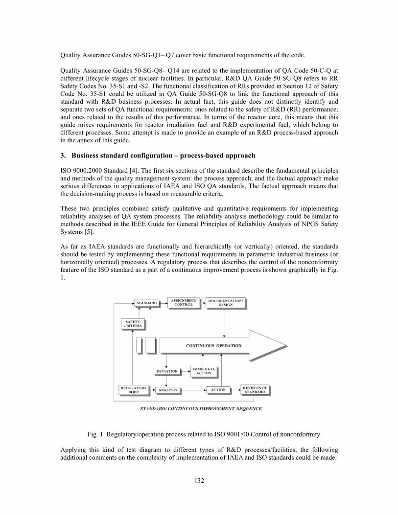
132
Quality Assurance Guides 50-SG-Q1– Q7 cover basic functional requirements of the code. Quality Assurance Guides 50-SG-Q8– Q14 are related to the implementation of QA Code 50-C-Q at different lifecycle stages of nuclear facilities. In particular, R&D QA Guide 50-SG-Q8 refers to RR Safety Codes No. 35-S1 and -S2. The functional classification of RRs provided in Section 12 of Safety Code No. 35-S1 could be utilized in QA Guide 50-SG-Q8 to link the functional approach of this standard with R&D business processes. In actual fact, this guide does not distinctly identify and separate two sets of QA functional requirements: ones related to the safety of R&D (RR) performance; and ones related to the results of this performance. In terms of the reactor core, this means that this guide mixes requirements for reactor irradiation fuel and R&D experimental fuel, which belong to different processes. Some attempt is made to provide an example of an R&D process-based approach in the annex of this guide. 3. Business standard configuration – process-based approach ISO 9000:2000 Standard [4]. The first six sections of the standard describe the fundamental principles and methods of the quality management system: the process approach; and the factual approach make serious differences in applications of IAEA and ISO QA standards. The factual approach means that the decision-making process is based on measurable criteria. These two principles combined satisfy qualitative and quantitative requirements for implementing reliability analyses of QA system processes. The reliability analysis methodology could be similar to methods described in the IEEE Guide for General Principles of Reliability Analysis of NPGS Safety Systems [5]. As far as IAEA standards are functionally and hierarchically (or vertically) oriented, the standards should be tested by implementing these functional requirements in parametric industrial business (or horizontally oriented) processes. A regulatory process that describes the control of the nonconformity feature of the ISO standard as a part of a continuous improvement process is shown graphically in Fig. 1.
Fig. 1. Regulatory/operation process related to ISO 9001:00 Control of nonconformity.
Applying this kind of test diagram to different types of R&D processes/facilities, the following additional comments on the complexity of implementation of IAEA and ISO standards could be made:

133
• Concept of systemic continuous improvement has not been a basis for development of this IAEA operation-oriented standard. Otherwise, the logical combination of IAEA and ISO standards with provisions for statistical performance/process evaluation would be realized.
• IAEA made an attempt to compare ISO 9000:2000 and IAEA QA standards in Safety Report No.
22 [6]. Unfortunately, the process-based approach with measurable performance criteria was not discussed in this document. As a result, ISO 9000:2000 was recommended only for supplier QA programs.
4. Approach to R&D business and regulatory standards alignment One of the practical features of ISO 9000:2000-oriented nuclear business management is the mapping of processes with built-in regulatory requirements. This process mapping creates the basis for process parametric reliability evaluation—final mapping against major process parameters would allow the (QA) system performance to be measured in terms of process reliability. The reliability of process control and process result data is the most important criterion of the QA-process-based approach.
Fig. 2. Reliability diagram of mechanical integrity and leak testing of a fuel rod.
Therefore, the basis for any evaluation of processes is a reliable data management tool. A quality plan (QP), as a data-obtaining tool of the QA program, is suited to the analysis of the QA program. From the viewpoint of reliability theory [7], the QP can be treated as a system; thus, QP (QC) procedures should be evaluated as this system’s elements. Among the important measures of reliability is the availability factor—the probability of a unit (or system element) to operate satisfactorily at present instants of time. This type of QP-based system reliability diagram of mechanical integrity and leak testing for nuclear reactor fuel rod fabrication is depicted in Fig. 2. The diagram includes only acceptance inspection and test elements. In this particular case the availability of this information (data-obtaining) system is expressed as the probability of detecting specified defects or out-of-tolerance parameters. In other words, the probability of providing reliable QC data is calculated in terms of the availability factor. For the monotonic system presented, the availability factor of this system [8] is
ps=[1-(1-p1)(1-p2)(1-p3)(1-p4)] [1-(1-p1)(1-p2)(1-p5)] [1-(1-p1)(1-p2)(1-p6)] [1-(1-p1)(1-p2)(1-p7)],
where p1, p2, p3, … are availability factors for the system elements marked as 1, 2, 3,… in Fig. 2. In other words, p1, p2, p3, … are availability factors for the data provided by these acceptance tests.

134
Thus, using this equation, it is possible to make rough estimates of the availability factor ps—it is 0.69 for one of the real fuel rod manufacturing system. For the purpose of continuous system improvement, measurements of the importance of system components should be applied. A mathematical theory of component importance is described in relative maintenance and reliability literature [8]. The practical application of importance principles meets the continuous improvement requirements of ISO 9000:2000. The continuous improvement approach was graded in terms of component importance for mechanical integrity and leak test data reliability (see Fig. 2). This means that improvement efforts were focused on more important components, and improvements were measured in terms of a component availability index. Finally, the availability index of the whole system was improved to 0.85, which is close to data availability indexes for RPBCs. A system reliability diagram could be developed for evaluating the data reliability of nuclear fuel rod operational performance as a part of an R&D process. In this operational performance diagram, the whole fabrication data reliability diagram (see Fig. 2) will be presented by one element, with availability index equal to 0.85. Consequently, the availability factor for fuel performance data is an element of the data reliability system for fuel decay-product release. The level of decay-product release is the regulatory limit of reactor operational performance. The related grading approach of regulatory principles is also based on the safety importance of systems and components. This means that the same approach and reliability mathematical model (including importance theory) could be used for other regulatory licensed facility operational processes/key parameters, to determine in an integrated and systematic fashion whether the licensee is satisfactorily complying with the QA program requirements imposed by the regulations, and whether the licensee’s QA program is effective in providing adequate confidence in the observance of safety criteria. Similar QA plans and reliability diagrams could be used for the data availability factor for RR irradiation and experimental fuel rod manufacturing tests. The modular decomposition [8] of such systems for experimental fuel applications will provide a model for the reliability evaluation of the following R&D, design, and manufacturing data elements: • The reliability of initial data, and the accuracy and reliability of approximations used for R&D
computer codes. • The reliability of R&D fuel manufacturing specifications. • The reliability and accuracy of NPGS fuel specifications, including the elimination of so-called
“vague” or hidden specification parameters. • The reliability of operational data related to root-cause analysis of fuel rod leaking statistics [9]. Along with providing reliability diagrams, FMEAs and fault tree analyses are used at in first stages of complex system analysis.
5. Conclusions Although the application of QA standards (code and guides) differs a lot for different configurations of facilities and lifecycle stages, especially for R&D the proposed method is a suitable way of QA evaluation in the nuclear industry, because • this method uses the same methodology and theory as PSA, which is proven by practice. • the method could be limited to different levels of complication, beginning from systemic expert
evaluation up to the application of a statistical Bayesian approach for the design of experiments. • at any of these levels the evaluation is based on measurable criteria without the loss of evaluation
system integrity. • a tool such as a fault tree analysis used in a PSA is similar to a decision-flow diagram that forms
the basis for (financial) business decision analysis theory—as an example, please see Howard Raiffa, Decision Analysis [10].
• the method naturally includes FMEA and reliability theory, as

135
6. References [1] “Quality Management systems – Guidelines for performance improvement”, ISO Standard 9004:2000, Geneva (2000) [2]. “Code on the Safety of Nuclear Research Reactors: Operation.” Safety Series No. 35-S2, IAEA, Vienna (1992) [3] “Quality Assurance for Safety in Nuclear Power Plants and other Nuclear Installations, Code and Safety Guides Q1-Q14”, Safety Series No. 50-C/SG-Q, IAEA, Vienna (1996) [4] “Quality Management Systems –Requirements”, ISO Standard 9001:2000, Geneva (2000) [5] “American National Standard – IEEE Guide for General Principles of Reliability Analysis of Nuclear Power Generating Station Safety Systems”, IEEE/ANSI Std 352-1987 [6] “Quality Standards: Comparison between IAEA 50-C/SG-Q and ISO 9001:2000”, Safety Reports Series No. 22, IAEA, Vienna (2002) [7] BARLOW RICHARD, PROSCHAN FRANK “Mathematical Theory of Reliability” SIAM, Philadelphia (1965) [8] BEICHEL FRANK, FRANKEN PETER “Zuverlässigkeit und Instandhaultung. Matematische methoden.” VEB Verlag Technik Berlin (1983) [9] CHESTAKOV I. Probabilistic-Statistical analysis of WWER Fuel Element Leaking Causes and Comparative Analysis of the Fuel Reliability Indicator on NPP’s with WWER and PWR Reactors, Proceedings of a Technical Meeting held in Bratislava, Slovakia, 17-21 June 2002, Fuel Failure in Water Reactors: Causes and Mitigation.IAEA-TEDOC-1345 p. 41-58 IAEA (March 2003) [10] RAIFFA HOWARD “Decision Analysis Introductory Lectures on Choices under Uncertainty, Harvard University”, Addison-Welsley, Reading, Massachusetts (1968)

136
REVIEW OF THE ACCIDENT SOURCE TERMS FOR ALUMINIDE FUEL: APPLICATION TO THE BR2 REACTOR
F. JOPPEN SCK•CEN
Boeretang 200, 2400 Mol, Belgium
ABSTRACT A major safety review of the BR2, a material test reactor, is to be conducted for the year 2006. One of the subjects selected for the safety review is the definition of source terms for emergency planning and in particular the development of accident scenarios. For nuclear power plants the behaviour of fuel under accident conditions is a well studied object. In case of non-power reactors this basic knowledge is rather scarce. The usefulness of information from power plant fuels is limited due to the differences in fuel type, power level and thermohydraulical conditions. First investigation indicates that using data from power plant fuel leads to an overestimation of the source terms. Further research on this subject could be very useful for the research reactor community, in order to define more realistic source terms and to improve the emergency preparedness.
1. Introduction BR2 is a material test reactor with a thermal power of 100 MW in operation since January 1963. A major safety review is to be conducted for the year 2006. This is a licence requirement. The objective of the safety review is to guarantee that a safe and reliable operation of the reactor is possible till at least 2016. One of the subjects selected for the safety review is the definition of source terms for emergency planning and in particular the development of accident scenarios. During the last years, the Belgian Authorities were already asking to prepare accident scenarios for the research reactors and for other nuclear installations. This article gives an overview of the information which is being used for defining BR2 accident source terms. For nuclear power the behaviour of fuel under accident conditions is a well studied with the PHEBUS project as one of the most important examples. The basic knowledge (the behaviour of the fuel under heavy transient or accident conditions) for defining such scenarios for non-power reactors is rather scarce. The usefulness of information from power plant fuels is limited due to the differences in fuel type, power level and thermohydraulical conditions. This article gives some thoughts about the behaviour of aluminide fuel plates under accident conditions. Information is gathered from publications about release of fission products from fuel plates, from reports on accidents where the SL-1 accident is a very rich source of information and from some own experience. 2. Accident scenarios and source terms Pre-defined accident scenarios have several advantages. They are an information source for the authorities to estimate the possible consequences of an accident and to assess the appropiate requirements for countermeasures. This information is useful for emergency preparedness exercises. In case of a real emergency, the scenarios can be used for fast communication with the authorities. Defining the scenarios is normally not a difficult task. A simple fault tree model (without probabilities) will be sufficient. Defining acceptable source terms is a more serious problem. Source terms for power reactors are a well studied issue, with the PHEBUS research project as an important example. The use of this information for research reactors will however lead to unrealistic source terms, due to differences in fuel type and thermohydraulical conditions.

137
Research reactors operate in most cases at cooling water temperature and pressure, but have in contrast a high power density and high coolant flow rates. This makes the thermo hydraulic analysis in transient conditions, after an initiating event, complicated. In many cases flow instability could occur caused by steam formation in a hot channel, although the coolant globally is still sub cooled. Calculation programs developed for power reactors have to be modified [1]. Reactivity effects are also different. Most of the research reactors with a higher power level can load a significant quantity of reactivity (several times prompt criticality). This can give more severe reactivity transients. On the other hand, the proportion of surface compared to quantity of fuel is much greater for plate type fuel than for pin type fuel. This will lead to more local boiling during overheating of the fuel plate and more negative temperature coefficients. Much information can be found about these effects can be found in the published reports of the SL-1 accident [2]. 3. Release of fission products from aluminide fuel plates in accident conditions BR2 uses at this moment uranium aluminide fuel plates with high enriched uranium. This fuel was developed the seventies and is known to have excellent irradiation behaviour [3]. However knowledge of what is happening under abnormal conditions is scarce. In case of insufficient cooling, the temperature of the fuel plate will rise and volatile fission products will be released. Information about the release of fission products is summarized in an overview article [4]. This reference is based on data from tests during which irradiated fuel is heated and the release of fission products is measured and from measurements during reprocessing of the fuel. The release rates are given, for each volatile isotope, as correlations that may vary with time, ambient temperature, burn up and fuel temperature. Predicting the fractions of fission predictions that will be released requires detailed modelling. In this context it must be understood that it concerns accident conditions, not releases occurring during normal operation. Release of fission products from aluminide fuels is observed when the temperature reaches about 560°C, at which blistering starts. The release increases when the solidus temperature of the cladding alloy is reached (about 585°C) and also at a temperature corresponding with the eutectical temperature of the aluminium-uranium alloy (650°C). More than 80% of fission gases and iodine will be released if the fuel is kept above the eutectical temperature. For other volatile isotopes, such as cesium and tellurium, the release will be slower and depends strongly on the burn-up. Release fractions depend also on the type of fuel and the correlations could be very complicate. As an example, smaller amounts of volatile fission products are released from dispersed fuel than form alloy fuel, but in case release of cesium from U3Si2-Al fuel the reverse was found [4]. 4. Incidents with research reactors leading to fission product release In order to have an idea of potential source terms for research reactors two possible accident scenarios will be discussed. One of these examples deals with fuel channel blockage and comes from experience with the BR2 reactor. The second comes from the accident of the SL-1 reactor in Idaho USA, which was destroyed due to a great reactivity insertion. 4.1 Blockage of fuel canal In the design of the Advanced Neutron Source Reactor by DOE (USA) much attention was paid to the potential consequences of fuel channel blockage which was considered as the main contributor to core damage initiating risk [5]. This paper calculates the consequences of blockage of a fuel channel. It starts from the assumption that the failure will propagate through the whole fuel assembly due to overheating of fuel channel. Calculations are continued until scram of the reactor which is supposed to be effective 4 seconds after the initial event. The report also studies the consequences of complete fuel destruction [6]. The partial blockage of fuel channel occurred in BR2 in 1975 at the start of cycle 5/75 [7]. The core of BR2 contains positions where fuel elements with an outer diameter of 200 mm can be irradiated.

138
These elements can be made of up to 13 concentric rings of fuel plates. The ring is composed of 8 sectors. These sectors are identical to the sectors of the Advanced Test Reactor of Argonne National Laboratory – USA. In 1975, during cycle 05/75, such an element (identification number A034) with thirteen rings of plates was loaded. A few hours after the start of reactor an automatic stop of the reactor occurred due to high activity of the primary water. The power of the reactor was at that moment 48.3 MW (60% of the reference power of that cycle). Analysis of the activity of the primary water indicated immediately that a significant surface of a fuel element must have been melted with an estimated surface between 40 and 120 cm²). The quantity of uranium lost in the primary circuit was calculated to be about 6 grams. Unloading of the core showed that the entrance of fuel element A030 was blocked by a foreign object. Figure 1 shows a photograph of the entrance of the element. The foreign object was identified as the plastic handle of a screwdriver that had fallen in the fuel channel during loading.
Figure 12: The damaged fuel element The accident is a good real case example of a fuel channel blockage. The initial signal for stop of the reactor came from the high pressure ionizing chambers mounted on the exit of the primary pipe. These chambers are used to measure nitrogen 16 activity in the primary circuit in order to have a direct indication of the power of the reactor. One of the three chambers is used for automatic regulation of the reactor power. High alarm on two out of three of the N-16 gives an automatic stop the reactor to protect against overpower. It is interesting to note that these chambers gave action before those designed to detect fission products. This is due to their close location to the core and their high sensitivity for γ- radiation. In the minutes following the accident the activity of krypton 88 in the primary circuit was measured by the on-line chains to be about 100 GBq/m³ giving a total quantity in the primary circuit of 15 TBq. Concentration of iodine 131 was measured to be 3.7 GBq/m³ or a total quantity of 550 GBq. Since BR2 has a closed loop, pressurized primary circuit, this activity remains mainly in the primary circuit and is removed by purification on resins, degassing and natural decay. Main inconvenience was that a number of locations were temporary inaccessible. After the accident, the purification with ion exchangers was set to maximum capacity (40 m³/hr for a volume of 150 m³). The concentration of krypton 88 decreased to 40 MBq/m³ and the iodine 131 to 22 MBq/m3. At this moment the reactor could be opened and the fuel unloaded, included the failed fuel element which could be unloaded without difficulty. During inspection of the fuel element in the hot cell some deformation of the fuel plates was observed due to the pressure drop behind the blockage. Higher than usual radiationlevels in the primary circuit were found at the heat exchangers. Radiation levels of the heat exchangers were up to 800 mSv/hr in contact with the heat exchangers and from 2 mSv/hr to 15 mSv/hr for the ambient. The reactor could be restarted two weeks after the accident From this accident it can be concluded that blockage of a fuel channel has no severe consequences for a loop cooled reactor if the primary circuit is equipped with fast detecting systems for activity of the water with automatic stop of the reactor in case of high activity levels. The situation is different for
139
pool reactors. A significant quantity of noble gases and some of the more volatile fission products would have been released to the reactor building and possibly towards the environment, leading to irradiation doses for personnel or public. 4.2 Reactivity induced accident [8] On 3 January 1961 an explosion occurred in the SL-1 reactor in Idaho Falls, USA. The SL-1 reactor, with a thermal power of 3 MW, was designed to produce electricity and heating in remote areas. The reactor was fuelled with 41 high enriched uranium plate type elements. The reactor contained 14 kg uranium. Cladding used was an aluminium nickel alloy. On the day of the accident the reactor was shut down for installation of flux wires. The work was finished and the operators were reconnecting the control rod drive mechanisms. During these operations the reactor became prompt critical, probably due to a pull out of a control rod leading to a nuclear excursion of the reactor. This resulted in an explosion which destroyed the internals of the reactor. The exact cause for the lifting of the control rod has never been clarified because the three operators were killed in the accident. The reactivity insertion was calculated to 2.4 ± 0.3 %, giving an energy release 130 ± 10 MW.sec [2]. Examination of the damaged fuel plates indicated that limited melting had occurred. 15% of core plate material was not recovered in an identifiable plate form. This missing portion of the core, having been in the high flux region, should have contained approximately 30% of the total fission product inventory and 1790 grams of U-235. It was further estimated from the fuel inventory that as much as 10% of the fission product inventory escaped from the reactor vessel. The radiological consequences were serious [9]. In the reactor building radiation fields of 5 Sv/hr were measured. Outside the building radiation fields varied between from 250 mSv/hr near the reactor building to 1.2 mSv on the road. 5.3 miles downwind of the reactor the average iodine concentration in air was approximately 0.2 Bq/m³ for the first 16 hours after the accident. Estimations of other releases were 4 GBq of strontium-90, 20 GBq of cesium-137 and appreciably lesser quantities of zirconium-niobium-95, cerium-144 and barium-lanthanum-140. The SL-1 accident gives a good idea about the consequences of an excursion of an aluminide fuelled reactor. It is not essential if the reactor was operational or in shutdown, as for the SL-1. For a reactor in operation the quantity of short lived fission products will be higher. It is important to mention that the SL-1 reactor had no containment building. Off-site consequences would have been limited if a containment building had been foreseen. 5. The maximum accident for an aluminide fuelled reactor In a number of publications, as for example [10], much attention is paid to the reaction of hot aluminium with steam. This is an exothermal reaction and produces hydrogen which could additionally explode. The actual BR2 maximum accident is based on this assumption. By using simple thermo dynamical consideration it can be shown that for most reactors not enough heat is produced for initiating this reaction in the full core. However it is still possible that the reaction occurs in certain locations such as a very hot fuel channel. This is, of course, very difficult to model. For preparing accident scenarios and estimating the source terms, following two accidents should be considered: • Blockage of a fuel channel. This could have serious consequences if it is combined with the non-
detection of heavy contamination in the primary water or a serious delay of the reactor scram. In case of early detection and stop of the reactor the consequences seem to be limited, especially in case of a reactor with closed primary circuit.
• Reactivity induced accidents. Due to the number of manipulations performed at research reactors, a potential for a reactivity induced accident is present. The precursor could be a loading error or the failure of a lifting device. However consequences for the environment seem to be limited if a containment building is present and if the violent aluminium-steam reaction could be ruled out.
140
6. Conclusions The behaviour of the fuel elements under abnormal condition is an essential topic in the development of accident scenarios for research reactors. Knowledge about this subject is rather scarce. Some research exists and experience from incidents and accidents is available, but there is no coordinated research as for power reactors. 7. References [1] A. Hainoun, A. Schaffrath, "Simulation of subcooled flow instability for high flux research
reactors using the extended code ATHLET", Nuclear Engineering and Design, 207 (2001), p. 163-168
[2] USAEC, "Additional Analysis of the SL-1 Excursion", IDO-19313, November 21, 1962.
[3] J. M. Beeston, R. R. Hobbins, G. W. Gisbson, W. C. Francis, “Development and Irradiation Performance of Uranium Aluminide Fuels in Test Reactors”, Nuclear Technology, Vol. 49, June 1980, pp. 136-149.
[4] R. P. Taleyarkhan, “Analysis and Modeling of Fission Product Release form Various Uranium-Aluminum Plate-Type Reactor Fuels”, Nuclear Safety, Vol.33, No.1, 1992, pp. 6-22.
[5] S. H. Kim, R. P. Taleyarkhan, S. Navarro-Valenti, V. Georgevitch, "Modelling and Analysis Framework for Core Damage Propagation during Flow-Blockage-Initiated Accidents in the Advanced Neutron Source Reactor at Oak Ridge National Laboratory", ORNL:TM-12945, September 1995.
[6] S. H. Kim, R. P. Taleyarkhan, S. Navarro-Valenti, V. Georgevitch, "Study on Severe Accident Fuel Dispersion Behaviour in the Advanced Neutron Source Reactor at Oak Ridge National Laboratory", ORNL:TM-12946, September 1995.
[7] SCK•CEN, Internal reports, 1975.
[8] USAEC, "IDO Report on the Nuclear Incident at the SL-1 Reactor", IDO-19302, January, 1962.
[9] John R. Horan, William P. Gammil, "The Health Physics Aspects of the SL-1 Accident", Health Physics, 1963, Vol 9, pp. 177-186.
[10] Ali Farahani, "Experimental Studies of Thermal and Chemcial Interaction Between Molten Aluminum and Nuclear Dispersion Fuels with Water", University of Wisconsin – Madison, 1997, DOE/ER/75713.
141
RESULTS OF OUT-OF-PILE TESTS OF THE MIR REACTOR IRRADIATED FUEL AT HIGH TEMPERATURES
A.L. Izhutov, V.V. Alexandrov, A.F. Grachev, Y.Y. Kosvintsev, A.E. Novoselov, Z.I. Chechetkina
State Scientific Centre of Russia Research Institute of Atomic Reactors, 433510, Dimitrovgrad, Ulyanovsk region, Russia
ABSTRACT In the paper are presented the results of out-of-pile tests of the MIR reactor irradiated fuel elements, to determine blistering initiation temperature. Fuel elements were made by extrusion method and had a round tube shape. Fuel meat – 90% enriched uranium dioxide particles, dispersed in an aluminum matrix, with density of uranium ~ 1 g/cm³, fuel elements cladding material - aluminum alloy SAV-6. A standard MIR reactor fuel element assembly consists of 4 round shape tubes, concentrically inserted in one another, with their outside diameters being 70, 61, 52, 43 mm correspondingly, cladding thickness being ~ 0.72 mm, fuel meat thickness ~ 0,56 mm, core height ~ 1000 mm [1]. Fuel gaseous swelling with hemispheric ~ (2÷5) mm blisters formation on the fuel elements surface starts at temperatures ~ (450÷480)°C. Porosity formation and fuel meat cracking started at the boundary of diffusion fuel-matrix interaction layer and matrix material out of fission products, accumulated and located in outside of fuel particles.
1. Introduction Instead of uranium aluminide (UAlx), uranium dioxide (UO2) with similar 90%, enrichment had started to use as fuel for the MIR reactor since the mid-80s of the last century. At that period, practically, all the Russian-made reactors passed over to higher density dioxide fuel. Then, the majority of low- and medium-power research reactors was converted from high enriched to mean enriched 36% uranium within the Russian fuel enrichment reduction program. To validate application of uranium dioxide in the MIR reactor fuel elements, were performed the necessary tests and post-irradiation investigations, including out-of pile studies of irradiated fuel at high temperatures. The main objective of these investigations was to determine the maximum attainable temperature range, which when achieved, gives start to fuel elements blistering process. That parameter is one of those needed to analyze safety in emergencies with worsening heat removal from the core, such as loss of flow and loss of coolant in the primary reactor circuit. Thermal tests were run on a specially designed in-cell experimental rig, equipped with system of monitoring fission products release from fuel elements. There were performed tests of the full-scale MIR reactor fuel elements with outside diameters of 52 mm and 43 mm, and with maximum fuel burn-up ~36% and ~41% correspondingly, those from standard fuel assemblies. Maximum heat flux from fuel elements surface is of ~ 4.0 MW/m². Maximum fuel temperature is of ~180°C. 2. The experimental arrangement for thermal test of irradiated fuel elements The schematic diagram of experimental installation, mounted in hot cells, is shown in figure 1. To heat fuel elements was used an electric muffle furnace ~70 mm in diameter and ~1400 mm in length. The furnace provides isothermal condition on the operating area of 1100 mm in length within temperature range of ~500°C with no more than ± 4°C variation. Fuel elements were placed into a quartz ampoule with 65-mm inner diameter. Argon was blown through it to form the inert atmosphere and to transfer fission products to the gamma radiation detector. To measure fuel elements temperature were used

142
Fig.1. Installation for irradiated fuel elements thermal tests.
Chromel-Copel thermocouples, located in 3 points along the fuel elements length. The temperature was recorded by means of a controller connected to a computer, measuring and recording precision being ± 2.5°C. To feed inert gas were used a pressure vessel, connected to the pressure regulator, ampoule with the fuel element, mechanic filter for hard dispersed particles trapping, metering reservoir, flow meter and aerosol filter. The sequence used to perform the experiment: _ mounting the fuel element into the ampoule and furnace, blowing argon through the fuel element and determining background
value of gamma activity in the metering reservoir; – heating the fuel element from ~ 25°C to the temperature set value at the rate of ~ 0.1°C/s; – keeping within the isothermal range during 300 seconds; – cooling to 25°C at the rate of ≤ 0.2°C/s; – dismantling the device and inspecting fuel element. Fuel element Ø52 mm was heated twice, first to 450°C, then, when the visual inspection and outside diameter measuring had not revealed any traces of blistering, the fuel element was heated for the second time to 480°C. Fuel element Ø43 mm was heated to 515°C. 3. Results of tests Before and after thermal tests there had been carried out visual inspection, profilometry and gamma scanning of fuel elements. After tests was performed metallography of the samples cut out of both fuel elements. Thermal tests have shown that the temperature of fuel elements blistering initiation exceeds 450°C. When fuel elements were heated to 480°C and 515°C the strongly expressed blistering occurred, however, no leak of fuel elements was detected, that is evident from both the results of gas-carrier specific activity metering, and visual and metallography study results. Distributions of integral gamma-activity, 137Сs, 134Cs and 95Zr isotopes along fuel elements length before and after tests practically coincide, i.e. no fission products redistribution along the fuel elements length occurred as a result of their heating. Fuel elements profilometry in two mutually perpendicular planes showed slight reduction of the fuel elements average outside diameter: to ~ 0.2% on the fuel element Ø52 mm and to ~ 0.1% on the fuel element Ø43 mm. At the same time were detected some local areas of fuel elements, where the outside diameter increased to 0.5%. In fig. 2 are shown typical views of fuel elements outer surface: 2a – with no thermal tests; 2b – fuel element Ø52 mm after heating to 480°C; 1c – fuel element Ø43 mm after heating to 515°C. Because of heating the color and the structure of oxide film on the fuel element cladding has changed; as is seen, the film is getting darker; here and there, it breaks off the surface. On the outer surface of the fuel element of Ø43 mm after heating to 515°C are distinctly seen the areas with local cladding deformation. In fig. 3 are shown typical views of fuel elements inner surfaces: 3a – with no thermal tests; 3b – fuel element Ø52 mm after heating to 480°C; 3c – fuel element Ø43 mm after heating to 515°C. After

143
thermal tests on the inner surfaces of both fuel elements are seen spots with local cladding deformation and hemispheric blisters formation of up to ~ (2…5) mm in diameter at the base. It is worth mentioning, that on the fuel element heated to 515°C the blisters are bigger and more numerous than those on the fuel element heated to 480°C, and that on the medium height area of fuel elements they are more numerous than those on the top and bottom. It is interesting that cladding deformation with blistering occurred mainly on the inner surfaces of fuel elements. In fig. 4, 5 and 6 are shown macro and microstructures of fuel elements fragments.

144
Non-heated Heated to 480°С Heated to 515°С fuel element Ø61 mm fuel element Ø52 mm fuel element Ø43 mm
а b c
Fig.2 Outer surface
а b c
Fig.3 Inner surface
а b c
Fig.4 Macro structures of fuel elements fragments
а b c
Fig.5 Micro structures of fuel meat, х 50
а b c
Fig.6 Micro structures of fuel meat, ×200
145
On the fuel element sample, that was not exposed to thermal tests (fig.4a, 5a, 6a), particles of fuel are tightly bonded with the matrix and porosity and cracks are missing, interaction layer between fuel and matrix is ≤ (4÷8) μm in thickness. On the fuel element surface there is a thin homogeneous oxide film. In a result of fuel elements overheating, porosity of considerable magnitude was formed in the fuel meat (fig.5b and 5c). Observing the fuel microstructure, one may see that porosity formation process is followed by matrix cracking. Cracks are forming along the boundary of interaction layer and matrix, and they grow in dimension and spread in the matrix, then they merge in certain areas, forming large gaseous pores (fig.6b and 6c). 4. Results discussion At temperature being ~500°C, diffusion of gaseous fission products in uranium dioxide is negligible, and their release into the interaction layer or into the matrix by diffusion mechanism is negligible during the short time of thermal tests. Therefore, gaseous swelling of fuel followed by formation of blisters of considerable dimensions on the cladding could occur only due to gaseous fission products, located outside fuel particles. Fission products release beyond the boundaries of UO2 particles, including gaseous ones, that make up ~25% from their total amount, under operation temperatures in reactor not more than 180°C, could happen due to 2 following majority processes. There are direct pass of fission products into the matrix from surface zones of fuel particles due to big kinetic energy and diffusion interaction between fuel and matrix. Uranium dioxide interaction with aluminum matrix at such a temperature level being possible only due irradiation impact of fission products and other types of irradiation on adjacent layers of fuel and matrix [2]. Since at least before 500°C, during short periods of time interaction between uranium dioxide and aluminum under out-of-pile conditions does not occur. Mean pass of fission products in the material can be evaluated by the ratio as follows [3]: R = (7.55 + 3.88 As Zs
-1/2) ρs-1, (1)
where: R - mean pass of fission products in the material (μm); As, Zs и ρs - relative atomic
mass, atomic number and material density (g/cm³), correspondingly. In the aluminum matrix the mean pass of fission products, calculated to ratio (1) makes up ~ 13 μm, that is why with certain concentration gradient in this layer there could be fission products. Indeed, one should bear in mind, that in diffusion interaction layer that represents a UAlx phase concentration of fission products should be considerably higher due to inter-diffusion with adjacent fuel layer, containing fission products, and due to fission of uranium contained in that layer. Besides, in this layer, considerable irradiation damage takes place, and there is a possibility of micro porosity generation with gaseous fission products already in the process of fuel application in core to vacancy mechanism. Gas pressure in the micro pore can be expressed by Van der Waals equation:
⎟⎠⎞
⎜⎝⎛ −
=
g
gg
nr
kTnP
βπ 3
34
, (2)
where: Pg – gas pressure, k – Boltzmann constant, T – absolute temperature, r – pore radius,
β – Van der Waals constant, ng – number of gas atoms.

146
When heated, pressure in pores increases in direct proportion to absolute temperature, and in case, when gas pressure in pores starts exceeding pressure of external forces and those of medium surface tension, then radius extends, that leads to reduction of pressure in accordance with equation (2) to equilibrium state determined by ratio as follows:
Pg = Р + 2 σ /r, (3)
where: Р – pressure due to external forces and structural characteristics of fuel element, σ – surface tension, r – pore radius. With further heating pores become larger, they merge, and finally that leads to fuel elements blistering. The fact that pore formation in the above experiments occurred along the boundaries of interaction layer and aluminum matrix, can serve an evidence of low surface tension, i.e. insufficient adhesion between matrix and interaction layer. It is also worth mentioning, that adhesion along the boundary between fuel particles and interaction layer is considerably better, than between interaction layer and aluminum matrix. In case fuel blistering occurs on the boundary between diffusion layer and matrix, one of the ways to increase fuel blister resistance could be alloying of matrix material. In paper [4] have been reported the results of blistering study and consecutive release of fission products from irradiated plate type mini fuel elements 50×115 mm with U-Alx fuel having density of ~2 g/cm³, enrichment ~40% and burn-up ~60%. Blistering on these fuel elements occurred within temperature range of ~ (550÷560) °C, that is much higher than the temperature of blistering compared to the described experiment. The difference could be connected with types of fuels, design features of fuel elements, as well as, operation conditions and those of thermal tests. However, it is probably fuel meat type that is the main factor, since in paper [4] there is a reference to the results of fuel elements tests with fuel meat based on U3O8 and U3Si for which blistering started at temperatures below 500°C. 5. Conclusion Out-of-pile tests of the MIR reactor irradiated fuel element with high enriched dioxide fuel with uranium density ~ 1 g/cm³ and burn-up ~40% had shown that within the temperature range of (450÷480) °C there starts the process of fuel elements gaseous swelling and blistering. However, the fission products release from under the cladding into the atmosphere is negligible, and fuel elements dimensions changes are local. Porosity formation and fuel meat cracking starts at the boundary of diffusion fuel-matrix interaction layer and matrix material. Fuel gaseous blistering occurred due to of gaseous fission products, accumulated outside fuel particles during the operation. 6. References 1. A.F. Grachev, A.L. Ijoutov, A.E. Novoselov et. al. “The MIR reactor fuel assemblies operating experience”, 6th International Topical Meeting on Research Reactor Fuel Management, Ghent, Belgium, march 17-21, 2002. 2. S.T. Konobievski et. al. Proc. Conf. on New Nuclear Materials Technology, Including Non-Metallic Fuel Elements New, IAEA: Prague, 1963, vol. 1, p. 269-282. 3. S. Kahn, V. Forgue. “Range-energy relation and energy loss of fission fragments in solids”, Phys. Rev., 1967, v. 163, p. 190. 4. T. Shibata, J. Posey, J. Snelgrove. “Release of fission products from irradiated aluminade fuel at high temperatures”, Nuclear Science and Engineering, v. 87, 405-417 August 1984.
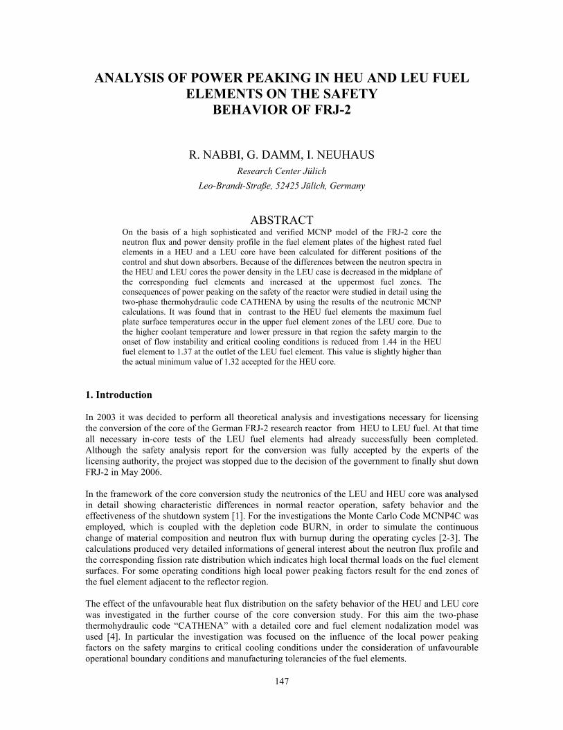
147
ANALYSIS OF POWER PEAKING IN HEU AND LEU FUEL ELEMENTS ON THE SAFETY
BEHAVIOR OF FRJ-2
R. NABBI, G. DAMM, I. NEUHAUS Research Center Jülich
Leo-Brandt-Straße, 52425 Jülich, Germany
ABSTRACT
On the basis of a high sophisticated and verified MCNP model of the FRJ-2 core the neutron flux and power density profile in the fuel element plates of the highest rated fuel elements in a HEU and a LEU core have been calculated for different positions of the control and shut down absorbers. Because of the differences between the neutron spectra in the HEU and LEU cores the power density in the LEU case is decreased in the midplane of the corresponding fuel elements and increased at the uppermost fuel zones. The consequences of power peaking on the safety of the reactor were studied in detail using the two-phase thermohydraulic code CATHENA by using the results of the neutronic MCNP calculations. It was found that in contrast to the HEU fuel elements the maximum fuel plate surface temperatures occur in the upper fuel element zones of the LEU core. Due to the higher coolant temperature and lower pressure in that region the safety margin to the onset of flow instability and critical cooling conditions is reduced from 1.44 in the HEU fuel element to 1.37 at the outlet of the LEU fuel element. This value is slightly higher than the actual minimum value of 1.32 accepted for the HEU core.
1. Introduction In 2003 it was decided to perform all theoretical analysis and investigations necessary for licensing the conversion of the core of the German FRJ-2 research reactor from HEU to LEU fuel. At that time all necessary in-core tests of the LEU fuel elements had already successfully been completed. Although the safety analysis report for the conversion was fully accepted by the experts of the licensing authority, the project was stopped due to the decision of the government to finally shut down FRJ-2 in May 2006. In the framework of the core conversion study the neutronics of the LEU and HEU core was analysed in detail showing characteristic differences in normal reactor operation, safety behavior and the effectiveness of the shutdown system [1]. For the investigations the Monte Carlo Code MCNP4C was employed, which is coupled with the depletion code BURN, in order to simulate the continuous change of material composition and neutron flux with burnup during the operating cycles [2-3]. The calculations produced very detailed informations of general interest about the neutron flux profile and the corresponding fission rate distribution which indicates high local thermal loads on the fuel element surfaces. For some operating conditions high local power peaking factors result for the end zones of the fuel element adjacent to the reflector region. The effect of the unfavourable heat flux distribution on the safety behavior of the HEU and LEU core was investigated in the further course of the core conversion study. For this aim the two-phase thermohydraulic code “CATHENA” with a detailed core and fuel element nodalization model was used [4]. In particular the investigation was focused on the influence of the local power peaking factors on the safety margins to critical cooling conditions under the consideration of unfavourable operational boundary conditions and manufacturing tolerancies of the fuel elements.

148
2. Description of the fuel elements and reactor core The reactor core of the FRJ-2 consists of 25 fuel elements which are arranged to 4, 6, 5, 6 and 4 fuel elements in five rows (see Fig. 1). Beside and between the fuel element rows the control and shut down absorbers - the so called course control arms (CCA) - are located.
3. Neutronic and thermohydraulic modelling For the determination of the axial and azimuthal power distribution in each single fuel tube of the fuel elements 3-dimensional MCNP calculations were accomplished. These MCNP calculations are based on a very detailed and well benchmarked model of the reactor core and the neighbouring reflector structures [2]. Calculations were performed at different CCA positions to realise the influence of the CCA angle especially on the axial power distribution. For the analysis of the thermalhydraulics of the reactor core the code CATHENA was used, which is able to include subcooled boiling and possible flow instabilities caused by a net steam generation in the subcooled liquid in a complex piping network. The flow instability is one of the thermodynamic limits, which restrict the maximum possible fuel element power. The thermohydraulic model contains a simplified idealization of the whole primary coolant circuit with pumps, pipings and heat exchangers. The reactor core itself is modelled in more detail, consisting of an exact model of the highest rated fuel element and 3 further models representing the remaining 24 fuel elements which are divided in 3 groups according to the power level in the core. In the model of the average fuel element (for each group) the 4 fuel tubes are represented by one which is surrounded
Fig. 1: Arrangement of the fuel elements and coarse control arms inside the reactor tank
A1-A4
B1-B6
C1-C5
D1-D6
E1-E4 1320 1320 1 40 0 1400
1320 1320 1320 1 400 1400 1 32 0
1320 1320 1320 1320 1320
1320 1320 1320 1320
1400 1400 1400 1320 1320 140 0
Fig. 2: Power limits (kW) of the individual fuel elements in the core
During an operational period of the FRJ-2 the CCAs are continuously moved out of the reactor core to compensate reactivity losses due to burnup. Each of the 25 fuel elements consists of four concentric fuel tubes. The height of the active fuel zone is approx. 60 cm. The fuel tubes are surrounded by a fuel free shroud tube and rigged internally with a fuel-free thimble. With the shroud tube and the inner thimble concentric annular gaps of same gap width are shaped. Thus hydraulic conditions on both sides of the fuel plates of all fuel tubes are similar. The coolant (D2O) enters through the grid plate the fuel elements at their feet ends and pours out above the fuel tubes by lateral openings in the shroud tube into the reactor tank. Due to the location of the three inlet pipes underneath the grid plate the coolant flow rates in the individual fuel element positions are different. For the 8 fuel element positions, which have the highest coolant throughput a larger maximum permissible fuel element power has been specified (see Fig. 2).

149
by an inner and an outer cooling channel. In the CATHENA model the cooling channels are hydraulically connected to the plenum underneath the grid plate at the coolant inlet and the reactor tank at the coolant outlet. The whole hydraulic path from the lower plenum to the upper part of the tank through the cooling channels was divided into three segments representing the inlet section, cooling gap and outlet section including the holes. For the calculation of heat transfer from the heated wall to the fluid in the whole flow regime, the appropriate correlations were chosen including the Mirshak's correlation for the onset of critical heat flux. The friction losses of the inlet and outlet sectors are modelled by flow resistances, which are adapted from the hydraulic measurements. The pressure losses in the fuel zones are calculated by CATHENA for the given geometric and thermohydraulic boundary conditions taking into consideration their influence on the flow distribution. The distribution of the heat flux generated in 15 different axial fuel rings is managed in CATHENA by applying the axial power peaking factors from the neutronic calculations. Due to the small thickness of the fuel tubes the process of the thermal conduction is considered in radial direction only whereas for the coolant in the narrow cooling channels axial flow is assumed. 4. Results of the simulations and analysis
The axial distribution of power density in the highest rated fuel element (central position of the core) is depicted in Fig. 3 for two different angles which the CCA reach during the operation at MOC and EOC. Accordingly, the axial profile considerably changes and the maximum power density in the midplane of the fuel element decreases with the upward movement of the CCA in favour of the upper and lower fuel zones of the fuel element. There is a distinct rise of power density which takes place in the last segment of the fuel element independent of the CCA angle and fuel type. For the LEU fuel element, the increase of the power density in the uppermost fuel zones is higher than in the HEU fuel element.
In contrast to the vertical flux buckling an power increase in the uppermost fuel zone takes place due to the dominating effect of the adjacent reflector which causes an enhanced thermalization of the fast
5,0
6,0
7,0
8,0
0 10 20 30 40 50 60
Distance from core bottom (cm)
LEU40°
HEU40°
LEU23°
HEU23°Ax. peaking fac.(%)
Fig. 3: Axial distribution of the power peaking factors in the HEU and LEU fuel element for 2 different CCA positions

150
neutrons and shifting the neutron spectrum. In the LEU fuel element, this phenomenon is relatively higher due to the effect of the fuel, moderator and reflector neutronic interactions resulting from the differences in the fuel composition.
. For a comparison, the neutron flux in the whole energy range is given in Fig. 5 in a LEU fuel element as an average spectrum and in the last fuel segment. In the latter case the neutron flux in the thermal energy range shows an appreciably higher value than the average spectrum in the fuel element. The ratio amounts to 1.35 indicating a higher power peaking factor in the end zone of the LEU fuel element. The shift of the neutron spectrum to the thermal range results on the other side in a decrease of the epithermal and fast energy region (Fig. 4) beginning at 0.20 eV.
Fig. 4: Fraction of the thermal n-flux in the fuel layers to the average of thermal flux in the highest rated fuel element
1,0E-04
1,0E-03
1,0E-02
1,0E-01
1,0E+00
1,0E-09
1,0E-08
1,0E-07
1,0E-06
1,0E-05
1,0E-04
1,0E-03
1,0E-02
1,0E-01
1,0E+00
1,0E+01
n-Energy in MeV
0,0
0,5
1,0
1,5
2,0Ratio
Whole fuel zoneLast fuel zone
Ratio
Fraction of n-flux
0,8
0,9
1,0
1,1
1,2
1 2 3 4 5 6 7 8 9 10 11 12 13 14 15
HEU LEU
Bottom No. of axial zones TopTherm. n-flux
The phenomenon of power peaking in the uppermost fuel zone of the highest rated fuel element was investigated in detail by analyzing the neutron spectrum in all axial fuel segments and demonstrated in Fig. 4. The results show the fraction of thermal flux to the total in 15 axial fuel zones according to the axial segmentation in the MCNP model of the fuel element averaged over the azimuthal and radial nodes. Accordingly the neutron flux in the uppermost fuel zone has an appreciably higher thermal fraction. In comparison to the spectrum of the whole fuel element the ratio in this zone amounts to 1.18 indicating a high fraction of thermalized neutrons in this region (HEU 1.13 %).
Abb. 5: Comparison of the average neutron spectrum in the fuel element and in the uppermost fuel zone

151
The consequences of power peaking on the safety of the reactor were studied in detail on the basis of the CATHENA model. For the distribution of the power density in the fuel plates of the fuel elements the results of the neutronic calculations with detailed axial power peaking profile were used. To account for uncertainties resulting from the inhomogenity of the fuel distribution, the power peaking factors in the nodes with the highest power density (midplane and ending) were increased by 13.5 % in accordance with the specified tolerances. The local inhomogenity was only applied to the outermost fuel tube (4th one) of the highest rated fuel element with the highest power density. In addition a reduced width was assumed for the adjacent cooling gap in order to account for the variation and tolerances of the channel width.
The results of the calculations are given in Fig. 6 for the highest rated fuel tube with the highest power density in the LEU core. Accordingly the maximum fuel temperature (surface temperature) expectedly appears in the uppermost node of the fuel plate. Due to the higher coolant temperature and lower local pressure, the undercooling and hence the safety margin against critical cooling conditions reach its minimum in this zone. For the determination of the safety margin to critical heat flux (CHF) the heat generation rate of the individual fuel element was gradually increased in the simulation runs until the level of the CHF according to the Mirshak’s correlation was exceeded and subsequently an oscillation of the flow (flow instability) took place in the channel in question. The results show that in this zone margin to CHF (burnout) and flow instability, respectively, falls to 1.41 and 1.37 which is higher than the actual limiting value for HEU (1.32). The analysis confirms that even unfavourable boundary conditions and power peaking caused by the reflector and spectral effect does not result in critical conditions and safe cooling of the fuel elements remains assured under normal operation as well as transient conditions.
50
70
90
110
130
0 10 20 30 40 50 60
Distance from core bottom in cm
Wall temp. in °C
100
110
120
130
140
Core midplaneInner surface
Outer surface
inner gap
outer gap
Fuel inhomogenity
Coolant temp. in °C
Fig. 6: Axial distribution of the surface and coolant temperature in the highest rated fuel tube

152
5. References [1] R. Nabbi, J. Wolters and G. Damm, “CHARACTERISTIC DIFFERENCES OF LEU AND HEU CORES AT THE GERMAN FRJ-2 RESEARCH REACTOR”, RRFM-Meeting, 2002, Ghent, Belgium [2] R. Nabbi and J. Wolters, “APPLICATION OF MCNP4B FOR CRITICALITY ANALYSIS OF FRJ-2”, RRFM-Meeting, 2000, Colmar, France [3] J. F. Briesmeister Ed. “MCNP-A GENERAL MONTE CARLO N-PARTICLE TRANSPORT CODE”, LA-12625-M, 1997, Los Alamos National Laboratory [4] R. Nabbi and J. Wolters “LOSS OF MAIN PUMPS IN THE RESEARCH REACTOR FRJ-2 WITH OR WITHOUT SCRAM” Book No. H00750-1992, The American Soc. of Mech. Engineers, PP 27

153
HEU TO LEU CONVERSION EXPERIENCE AT THE UMASS-LOWELL RESEARCH REACTOR
JOHN R. WHITE Chemical and Nuclear Engineering Department
University of Massachusetts Lowell, Lowell, MA 01854, USA
LEO M. BOBEK Radiation Laboratory
University of Massachusetts Lowell, Lowell, MA 01854, USA
ABSTRACT The UMass-Lowell Research Reactor (UMLRR) operated safely with high-enriched uranium (HEU) fuel for over 25 years. Having reached the end of core lifetime and due to proliferation concerns, the reactor was recently converted to low-enriched uranium silicide (LEU) fuel. The actual process for converting the UMLRR from HEU to LEU fuel covered a period of over 15 years. The conversion effort -- from the initial conceptual design studies in the late 1980s to the final offsite shipment of the spent HEU fuel in August 2004 -- was a unique experience for the faculty and staff of a small university research reactor. This paper gives a historical view of the process and it highlights several key milestones along the road to successful completion of this project.
1. Introduction The University of Massachusetts Lowell owns and operates a 1 MW MTR-fueled pool-type research reactor that serves as a nuclear-related research and training center for the University community, and provides irradiation services to a variety of industrial partners. The UMass-Lowell Research Reactor (UMLRR) operated safely with high enriched-uranium (HEU) fuel from early 1975 to the summer of 2000. At that time, the HEU fuel was moved to the fuel storage racks along the pool wall, and a completely new core fueled with low-enriched uranium silicide (LEU) fuel was loaded. After a few weeks, the startup tests for the new core were completed, and we have been operating successfully ever since with the new LEU fuel. Finally, in August 2004, the HEU to LEU conversion process came to full closure with the shipment of the 31 spent HEU fuel elements from UMass-Lowell to the Department of Energy (DOE) Savannah River Site. The actual process for converting the UMLRR from HEU to LEU fuel covered a period of more than 15 years. This paper highlights some of the key technical aspects of the HEU to LEU conversion. In particular, the paper gives a historical overview of the complete process, including: (1) the preliminary design work in the late 1980s, (2) the regulatory approval process in the mid 1990s, (3) the final design and analysis studies in 1999-2000, (4) the actual conversion process in 2000, and (5) the recent HEU fuel shipment that completed the overall conversion effort. 2. Historical perspective (1988 -1999) The process for converting the UMLRR from HEU fuel to LEU fuel began in early 1988. This effort was initiated in direct response to the 1986 NRC ruling that limited the future use of highly enriched uranium in domestically licensed research reactors in the U.S. [1]. At that time, we had limited in-house computational capability within the Nuclear Program at UMass-Lowell; so much of our initial effort was focussed on developing computer models and benchmarking a set of tools for the physics and safety analysis of research reactors. Our early work [2]-[3] centered on the development of a physics model for the existing HEU core and the comparison of reactivity and flux measurements
154
from the initial HEU startup tests [4] with the computed results. Based on the confidence gained from excellent comparisons to measured data from our early HEU models, we then used these same methods to perform some preliminary design and safety computations for several candidate LEU configurations [5]. This work continued with the evolution of a particular LEU assembly design containing 16 standard LEU plates and two aluminum end plates. This specific LEU16-18 element design was then used within a variety of possible configurations to arrive at a preliminary core design that could be used to drive the initial safety studies [6]-[7]. The culmination of all the early in-house design studies, physics modeling, and thermal hydraulic analyses, along with some help from the Reduced Enrichment for Research and Test Reactors (RERTR) group at Argonne National Laboratory (ANL) [8], was a preliminary reference fuel design and core configuration based on 20 standard, flat-plate, 19.75% enriched, uranium silicide (U3Si2) fuel elements, with a combination of radiation baskets and graphite or water reflector elements filling most of the remaining 9x7 array locations within the UMLRR grid plate. A sketch of the 1993 LEU design, along with a typical 29-element HEU core configuration for comparison, is shown in Fig. 1. Some of the key characteristics of the 1993 LEU core design are listed below: • The LEU assembly design has 16 uranium silicide fuel plates with 12.5 grams of U235 per plate
and 2 aluminum end plates (LEU 16-18 assembly), whereas the HEU element had 18 full plates with 7.5 grams of U235 per plate,
• The LEU core is a small 20-element high leakage core, • The LEU configuration contains a central flux trap facility with high fast and thermal fluxes (more
than a factor of three better than any experimental location in the HEU core), • The LEU fuel arrangement gives good blade worth symmetry for ease in operation and a high
shutdown margin, • The regulating blade is moved inward one position (D9 to D8) in its low-worth orientation, and • The LEU core gives equal or improved performance relative to the HEU core -- except for the
fluxes in the thermal column side of the core (reduced by about a factor of two). Based on the physics and safety studies for the 1993 LEU design, a final safety analysis for the HEU to LEU fuel conversion was submitted to the Nuclear Regulatory Commission (NRC) in 1993 and the base LEU design was approved later that year [9]. The NRC did make two additional requests for information based on the 1993 design and the appropriate supplements were submitted in 1994 and 1997. Finally, in July 1997, the UMLRR was issued an NRC order modifying the reactor license to convert from HEU to LEU fuel. However, due to insufficient DOE funding, manufacture of the LEU fuel for the UMLRR was not authorized until October 1999. During the interim between the NRC order and the funding authorization, the UMLRR reactor supervisor retired and was replaced. Upon review of the proposed LEU core configuration, the new supervisor initiated a design change to eliminate the modification to the regulating blade that was included as part of the 1993 core design.
29-Element HEU Core Configuration 20-Element 1993 LEU Core Layout
Fig 1. HEU reference and preliminary LEU core designs for the UMLRR.

155
3. Actual core conversion (1999-2000) In the summer of 1999, with the pending HEU to LEU conversion nearing reality, a major effort was undertaken to update our local modeling and calculational support capabilities at UMass-Lowell, to revive and improve upon the LEU computational models from the early 1990s, and to readdress the proposed movement of the regulating blade from the D9 position to the D8 position. This work produced the proposed new reference core configuration displayed on the left side of Fig. 2. This 21-element core with 19 full fuel elements and 2 partial elements was chosen as the best candidate for the initial startup of the LEU-fueled UMLRR. This design does not require any physical changes to the HEU core other than the replacement of the fuel assemblies and the re-configuration of the graphite reflectors and water/radiation baskets. While it does introduce some asymmetry in the blade worth distribution, the thermal column fluxes were improved without much sacrifice in the neutron levels seen in the primary in-core irradiation locations. The study also provided a wealth of computational information to help guide the actual core conversion process and to support the continued use of the experimental facilities within the new LEU core configuration [10]-[12]. The actual conversion process took place during the summer of 2000. The receipt and inspection of the new LEU fuel was completed in late July 2000 and, guided by the pre-analysis of the critical loading from Ref. 11, the LEU reactor core was loaded to a critical configuration on August 4, 2000. After achieving a final core configuration, which differed slightly from the proposed 1999 layout to allow greater excess reactivity (see Fig. 2), the process of evaluating the reactor operating characteristics was undertaken. After several weeks of reactivity evaluations, thermal flux mapping, reactivity coefficient measurements, etc., the new LEU core was found to operate essentially as designed. The key startup results along with some direct comparisons of the measured and computed results for the new LEU-fueled UMLRR are summarized in Refs. 13-14. These comparisons highlight several operating characteristics of the new core and they provide a direct evaluation of the models and methods used to design and characterize the new LEU core.
Target LEU Startup Core (M-1-2 Core) Actual LEU Startup Core (M-1-3 Core)
Fig 2. Target and actual LEU startup core designs for the UMLRR. 4. Shipment of HEU fuel
The final step of the HEU to LEU conversion process was to remove the used HEU fuel from UMass-Lowell and ship it to a Department of Energy (DOE) storage facility. The original plan was to ship the spent HEU fuel in the summer of 2001, but lack of funding at DOE delayed the proposed shipment date until 2002. During the interim, the events of 9/11 occurred. A result was substantial security changes to spent fuel shipment regulations, making such shipments essentially impossible without additional expert technical assistance.

156
In early June of 2004, UMass-Lowell received confirmation from DOE that funding would be made available to ship the used HEU fuel. For policy and legal reasons, DOE would not directly be responsible for shipments from universities, but would fund technical assistance. We began contract negotiations with NAC International, a company that provides spent fuel shipment services throughout the U.S. and the world. In July, NAC performed a site engineering assessment at UMass-Lowell and all the details of the final contract for shipment were worked out. NAC would be responsible for coordinating all activities outside of the university campus. This included informing and obtaining approvals from the appropriates agencies of all involved states, the Nuclear Regulatory Commission, the Department of Transportation, and the Department of Energy. In general, NAC would handle all the technical and engineering aspects of the transfer and shipment, including security during transport. During the period of contract negotiations, the reactor supervisor and director of radiation safety developed a Fuel Shipment Quality Assurance Program and related procedures to meet NRC regulatory requirements. The UML Reactor Safety Subcommittee (RSSC) met to discuss the details of the shipment, and to review and approve the quality assurance program. The QA program was then sent to the NRC for regulatory review and approval. During this time, NAC devised a five-day schedule to perform the fuel removal and shipment process. Several factors were considered for the start date: (1) the shipment had to occur prior to the academic year, (2) part of the transportation route included the State of New York and the shipment would not be allowed one week prior or during the national political convention taking place there, and (3) to minimize the impact on university activities, part of the schedule had to include a weekend. As a result, the schedule converged on a start date in mid August. The UMLRR is housed in a domed containment building. On one side of the containment structure is an exterior vehicle door with a clear 10 ft wide and 12 ft high opening. Inside the access door is an area sufficient to drive a large forklift into containment and close the door. The spent HEU fuel consisted of 31 MTR flat-plate elements. The UMLRR pool used for storing the spent fuel is approximately 12 feet wide by 16 feet long and 30 feet deep. The pool floor loading is 3000 lbm/ft2. Containment is equipped with a twin-rail polar crane. A 15-ton and a 2-ton crane are available to support cask-loading operations. Both crane hooks can be wetted. NAC employed the use of two LWT shipping casks, along with use of a transfer cask to shuttle baskets containing up to seven elements from the spent fuel pool to the LWT. Each LWT is capable of holding three fully loaded baskets. The actual process for shipping the HEU fuel began on August 12th with the staging of the NAC shipping casks and support equipment in the parking lot adjacent to the reactor building. The UMass-Lowell Police Department provided a 24-hour security and work-zone safety perimeter around the parking lot, preventing vehicle and pedestrian traffic. The NAC equipment and procedures were tested and the transfer of HEU fuel from the reactor building into the shipping casks began the next day. The fuel transfer operations were completed within 30 hours and the process of dismantling and packaging the NAC equipment for transportation was completed the following day. The Massachusetts State Police then performed a high-level vehicle inspection, specific for transportation vehicles carrying hazardous materials. On August 17th, the HEU fuel shipment left UMass-Lowell under State Police escort and arrived safely at the DOE Savannah River Site, Aiken S.C., the next day. A total of 31 irradiated HEU fuel assemblies were shipped. This last step in the whole HEU to LEU conversion process went smoothly and was rather uneventful. This step brought final closure to our 15+ year journey. 5. Summary experience
Our overall experience with this project was very positive at each stage of the process. Since we did not have a lot of prior experience with many of the tasks involved, a pro-active approach with the U.S. Nuclear Regulatory Commission (NRC) was taken. For example, we routinely requested guidance and oversight as needed, and even invited NRC inspectors to be on site to observe the actual LEU
157
startup process and the shipment of the HEU spent fuel. Our interaction with the U.S. Department of Energy (DOE) was also quite positive. DOE provided both the financial support and technical guidance needed for completion of this project. In particular, assistance from DOE provided support for the design analyses, fuel material and fuel assembly fabrication, and for the shipment of the used HEU assemblies to a DOE facility. In addition, the technical assistance provided by the RERTR group at Argonne National Laboratory was invaluable, especially in the early stages of this effort. Finally, with the combined effort of a number of University staff and students, the design, implementation, and operation of the new LEU core was quite successful and the final HEU fuel shipment, which brought closure to the conversion process at the UMLRR, was completed without incident. The LEU core, with some post-conversion improvements, has been in full operation for over 4 years now, and we expect that it will continue to provide enhanced operational capability to support the education and research mission of the UMLRR for many years to come. 6. References [1] U.S. Nuclear Regulatory Commission, “Limiting the Use of Highly Enriched Uranium in
Domestically Licensed Research and Test Reactors,” U.S. Federal Register, Vol. 51, No. 37 Feb. 25, 1986.
[2] J. R. White, J. E. Stoddard Jr., and J. P. Phelps, "Verification of the Computational Models for the Physics Analysis of the University of Lowell Reactor," Trans. Am. Nuc. Soc., 56, 574 (June 1988).
[3] J. R. White, J. E. Stoddard, Jr., and J. P. Phelps, "Physics Analyses for the HEU to LEU Conversion at the University of Lowell Research Reactor," 1988 International Reactor Physics Conference, Jackson Hole, Wyoming (Sept. 1988).
[4] J. P. Phelps, “Startup Report for the LTI Reactor,” Lowell Technological Institute (May 1975).
[5] J. E. Stoddard, Jr., "Conversion from High Enriched Uranium Fuel to Low Enriched Uranium Fuel for the University of Lowell Research Reactor," M.S. Thesis, University of Lowell (May 1989).
[6] R. S. Freeman, "Neutronics Analysis for the Conversion of the ULR from High Enriched Uranium to Low Enriched Uranium Fuel," M.S. Thesis, University of Massachusetts Lowell (May 1990).
[7] A. Amarnath, "Thermal Hydraulic Analyses of the HEU and the Proposed LEU Core Configurations of the UMass-Lowell Research Reactor," M.S. Thesis, University of Massachusetts Lowell (Sept. 1993).
[8] Letter from J. E. Matos, ANL to J. R. White, UMass-Lowell (January 1993).
[9] “FSAR Supplement for Conversion to Low Enrichment Uranium (LEU) Fuel,” Document submitted for review by the NRC for conversion of the UMass-Lowell Research Reactor (May 1993).
[10] J. R. White and R. D. Tooker, “Modeling and Reference Core Calculations for the LEU-Fueled UMass-Lowell Research Reactor,” ANS 1999 Winter Meeting, Long Beach, CA (Nov. 1999).
[11] J. R. White, J. Byard, and A. Jirapongmed, “Calculational Support for the Startup of the LEU-Fueled UMass-Lowell Research Reactor,” Proceedings of Topical Meeting on Advances in Reactor Physics and Mathematics and Computation, Pittsburgh, PA (May 2000).
[12] J. R. White, A. Jirapongmed, and J. Byard, “Preliminary Characterization of the Irradiation Facilities Within the LEU-Fueled UMass-Lowell Research Reactor,” Proceedings of Topical Meeting on Advances in Reactor Physics and Mathematics and Computation, Pittsburgh, PA (May 2000).
158
[13] “Report on the HEU to LEU Conversion of the University of Massachusetts Lowell Research Reactor,” submitted to the US Nuclear Regulatory Commission in fulfilment of Amendment No. 12 to License No. R-125 (April 2001).
[14] J. R. White and L. Bobek, “Startup Test Results and Model Evaluation for the HEU to LEU Conversion of the UMass-Lowell Research,” 24th International Meeting on Reduced Enrichment for Research and Test Reactors (RERTR 2002), San Carlos de Bariloche, Argentina (Nov. 2002).
[15] “Safety Analysis Report for the NAC Legal Weight Truck Cask,” NAC International, Docket No. 71-9225 T-88004 (May 2004).

159
THE UNITED STATES FOREIGN RESEARCH REACTOR SPENT NUCLEAR FUEL ACCEPTANCE PROGRAM:
PROPOSAL TO MODIFY THE PROGRAM
C.E. MESSICK U.S. Department of Energy
National Nuclear Security Administration Office of Global Nuclear Material Threat Reduction
Savannah River Operations Office P.O. Box A, Aiken, South Carolina 29802
United States of America
ABSTRACT The United States Department of Energy (DOE), in consultation with the Department of State (DOS), adopted the Nuclear Weapons Nonproliferation Policy Concerning Foreign Research Reactor Spent Nuclear Fuel in May 1996. The policy was slated to expire in May 2009. However, in October 2003, a petition requesting a program extension was delivered to the United States Secretary of Energy from a group of research reactor operators from foreign countries. In April 2004, the Secretary directed DOE undertake an analysis, as required by the National Environmental Policy Act (NEPA), to consider potential extension of the Program. On December 1, 2004, a Federal Register Notice was issued approving the program extension This paper discusses the findings from the NEPA analysis and the potential changes in the program that may result from implementation of the proposed changes.
1. Introduction DOE, in consultation with the Department of State (DOS), adopted the Nuclear Weapons Nonproliferation Policy Concerning Foreign Research Reactor Spent Nuclear Fuel in May 1996. The program was scheduled to expire in May 2009. The Foreign Research Reactor (FRR) Spent Nuclear Fuel (SNF) Acceptance Program is a critical component of U.S. nonproliferation efforts. The primary objective of the program is to reduce and eventually eliminate highly-enriched uranium (HEU) of U.S.-origin from civil nuclear applications worldwide. Since 1996, the Acceptance Program has conducted 31shipments involving 27 countries in the safe return of 6,445 spent nuclear fuel elements to the United States for management at Department of Energy (DOE) sites in South Carolina and Idaho, pending final disposition in a geologic repository. 2. Global Threat Reduction Initiative In May 2004, the FRR SNF Acceptance Program was incorporated as a key element in DOE’s newly established Global Threat Reduction Initiative (GTRI). GTRI’s mission is to identify, secure, remove or facilitate the disposition of vulnerable, high-risk nuclear and other radiological materials around the world ---as quickly and expeditiously as possible---that pose a threat to the United States and the international community. GTRI objectives include to:
• accelerate and complete the repatriation of U.S.-origin research reactor spent HEU fuel from locations around the world;
• work in partnership with Russia to repatriate Russian-origin HEU fuel from Russian-supplied research reactors;
• work to convert the cores of civilian research reactors that use HEU to use low-enriched uranium (LEU) fuel; and
• work to identify other nuclear and radiological materials and related equipment that are not yet covered by existing threat reduction efforts and rapidly address the most vulnerable facilities.

160
The National Nuclear Security Administration (NNSA) has made remarkable progress since this new initiative was launched last year. Representatives from approximately 100 countries attended the successful Global Threat Reduction Initiative International Partners’ Conference last September. In addition, under GTRI and the Russian Research Reactor Fuel Return program, NNSA has worked closely with the IAEA, the Russian Federation, and other countries to repatriate fresh HEU from Uzbekistan and the Czech Republic to Russia over the past 6 months. More than 10 other joint projects under GTRI are in the planning stages. Although the Acceptance Program has demonstrated significant progress, participation and shipping rates have not met initial expectations. As of the beginning of FY2005, DOE had received only about 35 percent of the material eligible for return as estimated in the Final Environmental Impact Statement on a Proposed Nuclear Weapons Nonproliferation Policy Concerning Foreign Research Reactor Spent Nuclear Fuel [1] (FRR SNF EIS). Several factors have contributed to lower than expected receipts. Several countries have burned fuel less rapidly than was expected in 1996. In addition, two countries (Belgium and France) decided to process their SNF at the COGEMA facility in France, and consequently have not participated in the program. These two countries were expected to contribute a significant percentage of the fuel elements projected for acceptance by 2009. However, it is deemed appropriate and acceptable to process SNF to LEU material. Finally, as discussed below, delays have been experienced in the development of alternative fuels. Under the GTRI, NNSA is working to overcome these obstacles by accelerating the development of higher-density LEU fuels, and accelerating the return of eligible U.S.-origin HEU spent nuclear fuel from research reactors. 3. Low-Enriched Uranium (LEU) fuel development The international community has experienced technical delays in the development of an alternate “processable” LEU fuel. The development and qualification of LEU fuel that can be processed is important to ensure FRRs are able to continue reactor operation in the foreseeable future and ensure proper disposition of SNF. Extending the Acceptance Program ensures a backend solution is maintained while progress continues in eliminating HEU in research reactor fuels. The most predominant LEU fuel being used today is uranium-silicide LEU fuel developed in the 1980s by DOE. Although processing studies concluded that the uranium-silicide fuel could be successfully processed at the Savannah River Site (SRS), disposition through a repository was chosen in lieu of processing at the SRS unless the physical condition of the fuel warranted a more immediate disposition. To date, no SNF received from the FRR SNF Acceptance Program has been dispositioned by processing in the SRS H-Canyon Separation Facility. The United Kingdom Atomic Energy Agency (UKAEA) demonstrated in laboratory scale trials [2] that uranium-silicide LEU fuel could be processed at its facility in Dounreay, Scotland. However, the capital investment in new equipment required for large-scale processing operations was determined to be uneconomical, and the facility was shutdown in 1998. COGEMA in La Hague France is the only remaining major potential processing facility. COGEMA has not processed uranium-silicide fuel on a commercial scale, and the facility would also require additional equipment for efficient processing operations. However, COGEMA is now accepting a limited quantity of uranium-silicide LEU fuel for processing, and is investigating the possibility of increasing the quantity that could be accepted for processing [3]. 4. Proposal to modify the acceptance program During the DOE-sponsored Reduced Enrichment for Research and Test Reactors (RERTR) Conference in Chicago in October 2003, a group of reactor operators and supporters (40 petitioners from 17 countries) prepared and delivered a petition to the U.S. Secretary of Energy. The petition requested that DOE extend the FRR SNF Acceptance Program until new LEU fuels become available, allowing reactor operators to convert to a LEU fuel type that has an identified disposition path. On
161
February 11, 2004, in a speech to the National Defense University, the President of the United States stated, “We will help nations end the use of weapons-grade uranium in research reactors.” On April 14, 2004, the Secretary of Energy directed the DOE’s National Nuclear Security Administration (NNSA) to consolidate the U.S. FRR SNF Acceptance Program within its nonproliferation mission, further directing the appropriate offices within DOE to initiate actions necessary to extend the FRR SNF Acceptance Program’s fuel acceptance deadline. As a result of these actions, DOE conducted an evaluation on the effects of extending the FRR SNF Acceptance Program and adding the Open Pool Australian Lightwater (OPAL) Reactor (formerly referred to as the Australian Replacement Research Reactor), documented in the Supplement Analysis for the Foreign Research Reactor Spent Nuclear Fuel Acceptance Program [4] in accordance with the National Environmental Policy Act (NEPA) regulations. DOE and the U.S. Department of State proposed to modify the FRR SNF Acceptance Program by:
• Extending the expiration date for irradiation of eligible spent fuel either 5 or 10 years, from May 12, 2006, to May 12, 2011, or May 12, 2016;
• Extending the acceptance date for eligible spent fuel either 5 or 10 years, from May 12, 2009, to May 12, 2014, or May 12, 2019; and
• Extending eligibility to Australia’s Replacement Research Reactor (RRR) for participation in the Acceptance Program.
The amount of eligible SNF would remain the same as identified in the original EIS, about 22,700 elements or about 20 metric tonnes of heavy metal (MTHM). The proposed program extension would not change other requirements contained in the EIS assumptions and EIS Record of Decision. However, target material (fuel for isotope production such as Technicium-99) and damaged spent fuel currently can only be treated in H-Canyon at SRS. Current DOE plans call for the SRS H-Canyon facilities to be maintained in operable condition through 2010 pending a review of the facility and DOE’s initiatives. Therefore, target material and damaged spent fuel would not be eligible for acceptance beyond 2009 under the proposed extension. 5. Analysis of the proposed action
The Supplement Analysis discusses the impact of the proposed action on the shipment schedule projected and analyzed in the FRR SNF EIS, and compares the likely effects that the proposed action would have on environmental resources to those analyzed in the EIS. The comparison focuses primarily on the radiological effects on human health and safety. Human health and safety is considered to be the most important resource, and radiological considerations are the most likely variables, to be affected by the proposed action. The Supplement Analysis also discusses the most significant assumptions used in the FRR SNF EIS to analyze the radiological effects on human health and safety, the conservatism of these assumptions based on experience gained from actual shipments to date, and assumptions that need to be changed because of the proposed action or because of new information available since the publication of the FRR SNF EIS in 1996. Key considerations evaluated in the Supplement Analysis include shipping schedules; normal and accident radiological consequences for marine, port, and ground transportation situations; and impacts to the management sites. A summary of these considerations is provided below:
Shipment schedule: The Supplement Analysis determined that shipment schedule projected over the extended period is expected to remain substantially lower than the constant shipping rate assumed in the FRR SNF EIS. Normal and Accident Radiological Consequences: The Supplement Analysis discusses the conservatism built into the original EIS radiological impact analysis and analyzed changed assumptions and actual conditions since the EIS. The evaluation of the normal and accident radiological consequences included bounding SNF fission product activity, transport packages used in the program, projected change in population density over the extended period, actual
162
transport package external dose rate from experience derived since the program’s inception, and the effect of receipt of the OPAL SNF. These factors were applied to analysis of marine transport, port activity, and ground transportation impacts. Accident and incident-free impacts of marine transport, port activity, and ground transportation activities were considered. The study found no significant increase in risk to marine shipping crews, port workers, or ground transportation workers as a result of the proposed program extension. The study found the proposed extension could increase the radiological risk to the general public near the port of entry or along ground transportation routes primarily due to population increases since 1996, but the risk remained within or slightly above the low risk calculated in the FRR SNF EIS. Impacts at SRS and the Idaho National Engineering and Environmental Laboratory: The Supplement Analysis determined that the proposed extension would not impact the total quantity of candidate SNF and that the SNF mass and receipt schedules would remain within DOE site-specific limits. The study also determined that the risk to workers and the general public from the addition of the Australian’s OPAL Reactor fuel assemblies would be too small to impact existing environmental impact calculations.
6. Conclusion The Supplement Analysis determined that an extension of the FRR SNF Acceptance Program for 5 or 10 years and inclusion of the Australian’s OPAL Reactor would not constitute a substantial change in action relevant to environmental concerns. Therefore, additional NEPA documentation to the FRR SNF EIS would not be required. The program extension was approved within DOE on November 23, 2004 and a formal issuance of an extension of the program occurred by the issuance of a Federal Register Notice [5] on December 1, 2004. The OPAL Reactor was added to the Supplement Analysis and the subsequent Record of Decision changed to accommodate a unique situation encountered by the Australian Nuclear Science and Technology Organization (ANSTO) as the HEU-fueled High Flux Australian Reactor (HIFAR) is replaced with the LEU fueled OPAL Conversion from HEU fuel to LEU fuel is effectively occurring as the HEU fueled HIFAR is shutdown and the LEU fueled OPAL is brought on-line. ANSTO has participated heavily in the development of high-density uranium-molybdenum LEU fuel, serving to benefit continued development of this fuel for other FRRs. Because the uranium-molybdenum LEU fuel will not be available in the timeframe required for commissioning of OPAL it is expected to operate for a limited period of time using uranium-silicide LEU fuel. Without confirmed processing options for all of this fuel, the Australian government has requested that the fuel be accepted under DOE’s FRR SNF Acceptance Program until processable uranium-molybdenum fuel becomes available. Subsequent to DOE’s determination that additional NEPA documentation to the FRR SNF EIS would not be required, DOE issued a change to the FRR SNF EIS Record of Decision. The change notice to the Record of Decision allows the program to be extended for an additional 10 years and includes the participation of the Australian’s OPAL Reactor. The issuance of a change notice to the Record of Decision also allows DOE to proceed in development of an implementation plan and guidance for the Acceptance Program extension. This information will be shared with FRR participants and other interested parties. Many currently participating FRR operators will not need to change their current shipping strategies and participation and shipping schedule will continue as currently planned. However, some FRR operators may need to change their participation schedule based on specific operational needs and requirements. It is not the intent of the FRR SNF Acceptance Program or the GTRI mission to prevent or disrupt the needed operation of a research reactor. The Program intends to assist reactor operators in conversion to LEU fuels while providing an acceptable disposition path for SNF involving uranium that was enriched in the United States. In accordance with the objectives of GTRI and the allowances provided in the FRR SNF Acceptance Program extension, it is expected that FRRs that are currently
163
using HEU fuel will convert to use LEU fuel as soon as possible with the understanding that SNF with uranium enriched in the United States can be dispositioned in the United States until May 13, 2019 provided the fuel is not irradiated after May 13, 2016. Operational strategies will be evaluated on a case-by-case basis based on these new considerations. As a result of these new GTRI activities, DOE is evaluating the FRR SNF Acceptance Program Fee Policy to determine how to accelerate and solidify shipment schedules. The United States remains committed to supporting worldwide nonproliferation goals such as those for which this program was designed. Accepting eligible fuel now rather than later remains a primary focus of that commitment. The United States hopes to work with all remaining eligible research reactors to plan for shipments of their eligible spent fuel, and DOE continues to support research reactor operators’ needs and seeks to meet any interested parties to further discuss the program 7. References [1] Department of Energy, Final Environmental Impact Statement on a Proposed Nuclear Weapons Nonproliferation Policy Concerning Foreign Research Reactor Spent Nuclear Fuel, DOE/EIS-0218F, February 1996 [2] Cartwright, P., 1996, “Reprocessing of LEU Silicide Fuel at Dounreay.” Proceedings of the 19th
International Meeting on Reduced Enrichment for Research and Test Reactors, Seoul, Korea, October 7-10, p. 418, United Kingdom Atomic Energy Agency, Dounreay, Scotland. [3] Auziere, P., 2004, “UMo Spent Fuel Acceptance Treatment at La Hague Plant.” Transactions of the 8th Topical Meeting on Research Reactor Fuel Management, Munich, Germany, March 21-24, p. 131, COGEMA, La Hague, France. [4] Department of Energy, Supplemental Analysis for the Foreign Research Reactor Spent Nuclear Fuel Acceptance Program, DOE/EIS-0218-SA-3, November 2004 [5] Federal Register Notice, Volume 69, No 230, Wednesday, December 1, 2004, Pages 69901 – 69903, Revision of the Record of Decision for a Nuclear Weapons Nonproliferation Policy Concerning Foreign Research Reactor Spent Nuclear Fuel.

164
R&D FOR THE FINAL DISPOSAL OF IRRADIATED RESEARCH REACTOR FUEL ELEMENTS
H. CURTIUS, H. BRÜCHER Institute for Safety Research and Reactor Technology
Forschungszentrum Jülich GmbH, 52425 Jülich, Germany
ABSTRACT R&D is going on in the Research Centre Jülich to investigate the long-term behaviour of U/Al and U3Si2 based fuels in salt, clay and granite repositories. Results from leaching experiments with irradiated U/Al fuel elements in salt brines show, that the fuel corroded within some months and that the mobilised radionuclides were trapped by the formed secondary phases. Treatment of these secondary phases with fresh brine resulted in a quantitative remobilisation of Cs and Sr, while Pu was not affected at all. A phase component of these corrosion products was identified as Mg-Al-Cl-hydrotalcite. The ability of this double layer hydroxide to trap 99Tc and 129I was investigated. Recently leaching experiments with non-irradiated U/Al and U3Si2 based fuel elements in clay pore water (Mont-Terri type) have started and the first results show that both types corroded. Work is in progress.
1. Introduction
Quite a great number of different types of spent fuel from research reactors exist in Germany. The general policy is to send fuel from MTRs and TRIGAs of US origin back to the USA as long as possible. An alternative option is reprocessing in Great Britain or France. For those fuels which cannot be returned to the USA or which will not be reprocessed with respect to economical reasons, a back-end option has been developed in Germany. It consists in dry storage in special casks and, later on, direct disposal in deep geological formations [1]. As deep geological formations salt, granite and clay are considered. In granite and clay formations pore water is always present but in a salt repository a water ingress and the subsequent formation of salt brines is considered as accident scenario. In the presence of these aquatic phases the corrosion of the fuel container and then the direct contact to the fuel itself is possible. The arising question “ If the fuel element will corrode, what will happen to the radionuclides” must be answered. This question in mind, first leaching experiments with a metallic U/Al-fuel element in salt brines and in granite water (Grimsel-West type) were performed [2]. From leaching experiments with granite water it was shown, that the U/Al-fuel element corroded so slowly that no corrosion products were obtained. Calculated by the radionuclide content found in solution a time period of 103 years is assumed for a complete dissolution of the fuel element. In contrast high corrosion rates of the U/Al-fuel element were obtained in salt brines, especially in magnesium chloride rich brines. The addition of cast iron (basic material of the fuel element container) had an acceleration effect. A complete dissolution of the fuel was observed within a couple of months. Under aerobic as well as under anaerobic conditions the bulk of released radionuclides were trapped by the formed corrosion products (secondary phases). As a crystalline phase component of the secondary phases a Mg-Al-Cl-hydrotalcite was identified [3]. As a results of these data new work packages were established in November 2003 and they can be summarised as follows:
Topic 1: Identification of parameters which determine the remobilization rates of the trapped radionuclides.
Topic 2: Syntheses of a Mg-Al-Cl-hydrotalcite and subsequent sorption experiments with repository relevant radionuclides

165
Topic 3: Leaching experiments with non-irradiated and irradiated U/Al- and U3Si2-fuel elements in repository relevant aquatic phases
First results from the work packages specified are presented subsequently. 2. Experimental set-up The experiments performed to determine the remobilization rates of trapped radionuclides were performed in hot cells. Corrosion products used for these studies were obtained by complete corrosion of an irradiated U/Al-fuel element plate (40 x 20 x 1.36 mm) in MgCl2-rich brine in the presence of iron under anaerobic conditions at 90 °C. To study dilution effects aliquots were treated with MgCl2-rich brine. The influence of the ionic strength was studied by the use of different concentrated MgCl2-brines. The fraction of inventory was determined by complete dissolution of some aliquots in 8 M HNO3 solution. All samples obtained were analysed radiometrically. The experimental set-up for the syntheses of the Mg-Al-Cl-hydrotalcite is described in [4]. The radioactive iodine and technetate solutions used were prepared from standard stock solutions. Sorption experiments were performed according to the batch technique. All samples were stored in glass tubes with occasional shaking under argon atmosphere for two days. Then all samples were filtered (450 nm) and the pH was measured. Aliquots of the solutions were analysed radiometrically. The solids were washed, dried and analysed by XRD and FT-IR. Blank experiments were performed too, indicating that the adsorption of I- and TcO4
- on the glass walls was negligible. Leaching experiments with the non-irradiated U/Al- and U3Si2-fuel elements were performed in glass autoclaves at 90°C in 400 ml of MgCl2 brine solution or in clay pore water (Mont Terri type) in the presence of 10 g FeCl2 under anaerobic conditions. The dimension of the U/Al plate was 28 x 20 x 1.5 mm with an amount of 1.20 g U total (U-235-enrichment: 89%). The dimension of the U3Si2 plate was 40 x 20 x 1.36 mm with an amount of 1.44 g U total (U-235-enrichment: 0.21%). 3. Results and discussion Topic 1: As it was pointed out the U/Al-fuel element corroded in MgCl2-rich brine. The radionuclides were mobilised first and then trapped by the formed corrosion products. In view of the long disposal
Fig.1 Remobilization rates of Cs in different concentrated salt brines and in water at 90°C
0
20
40
60
80
100
120
140
0 100 200 300 400 500 600 700 800 900 1000
time [days]
fract
ion
of in
vent
ory,
FO
I [%
]
fresh brine50 % conc. brine25 % conc. brinewater

166
time the behaviour of the radionuclides must be investigated under various geochemical conditions. Therefore the obtained secondary phases were aliquoted and then treated with “fresh magnesium chloride brine” to study the effect of dilution. Other aliquots were treated with different concentrated magnesium chloride brines to study the effect of ionic strength. As it is shown in Fig. 1 the radionuclide Cs is released quantitatively and the release does not depend on the ionic strength. The same results were obtained for strontium. On the other hand Pu, a long-lived actinide, which contributes strongly to the long-term dose rate of the spent fuel waste, is not affected at all. This different behaviour can be explained by the different chemistry of Cs and Pu. Cs can only act as a monovalent cation and has a poor complex chemistry. Pu can be present in different valent states and it has a wide complex chemistry.
Topic 2: The secondary phases may have a significant influence on radionuclide retardation. Therefor it was of interest to identify these secondary phases. Besides amorphous parts crystalline phases like bischofite, goethite and Mg-Al-Cl-hydrotalcites were identified. Especially the Mg-Al-Cl-hydrotalcite is of great interest. This substance also referred as anionic clay material is able to fix anionic species as well as cationic ones. To study the sorption effects with repository relevant long-lived radionuclides we first synthesised this Mg-Al-Cl-hydrotalcite and determined all analytical data. From these results the formula of the Mg-Al-Cl-hydrotalcite could be derived as: Mg3Al(OH)8Cl0.88 (CO3
2)-0.063 2.4·H2O.
Starting sorption experiments we first tested the ability to retard anionic species like iodine and technetate. For the Mg-Al-Cl-LDH (molecular weight: 314 g/mole) we calculated an anion exchange capacity of 2.8 E-03 mole/g (we did not consider the amount of carbonate ions present in the interlayer) for monovalent anions, which corresponds to 2.8 meq/g. That means, that for the used Mg-Al-Cl-LDH at most 2.8 E-03 mole/g of chloride in the interlayer can be exchanged by other monovalent anions. In kinetic studies iodine adsorption onto the Mg-Al-Cl-hydrotalcite reached equilibrium within 2 days and the adsorption rate reached 50%. The same experiments performed in 0.01 M MgCl2 solution led to a decrease in adsorption down to 30 %. Moreover in a 0.1 M MgCl2-solution no adsorption took place. These results can be explained by the effect of competition anion. In our case chloride is the competition anion. If a high chloride concentration is given, no exchange of iodine takes place because, compared to the iodine ion, the chloride ion has the higher affinity towards the Mg-Al-Cl-hydrotalcite. The sorption of technetate as function of time was studied too. Technetate behaved like iodine and again it was proven that chloride has the highest affinity towards the Mg-Al-Cl-hydrotalcite. The sorption of technetate and iodine was investigated as function of pH as well, and it was found that there is no dependency on pH in the used pH-range between 3.5 and 8. Then the adsorption isotherms were obtained by plotting the amount of metal ions adsorbed on Mg-Al-Cl-LDH, Cads against metal concentration in solution at equilibrium, Ce. The adsorption data were fitted to the Dubinin-Radushkevich (D-R) equation [5]. The mean energy of sorption is the free energy change when one mole of ion is transferred to the surface of the solid from infinity in the solution. The isotherms did fit the D-R-equation well as presented for iodine in Fig. 2. The value of the mean energy of the sorption in 0.01 M MgCl2 solution was found to be about 8 kJ/mole for iodine and for technetate and this is in the range for ion exchange reactions, i.e., 8-16 kJ/mole. The sorption capacity found by the D-R isotherm in 0.01 M MgCl2 solution was determined to be 1.97E-04 mole/g for iodine and 5.53E-06 mole/g for technetate. Compared to the calculated maximum anion exchange capacity of 2.8 E-03 mole/g these results predict that it is possible to exchange 7 % of the interlayer chloride by iodine in 0.01 M MgCl2 solution. In the case of technetate only 0.2% of the interlayer chloride can be exchanged.

167
Fig.2 D-R Equation for iodine in 0.01 M MgCl2 solution
Topic 3: In the third work package the corrosion behaviour of U/Al- and U3Si2-fuel elements in repository relevant solutions should be investigated. First experiments started with non-irradiated U3Si2-fuel elements and with non-irradiated metallic U/Al-fuel elements in MgCl2-rich brine and in clay pore water (Mont Terri-type). The H2 formation can be regarded as indicator for the progress of the corrosion (Fig. 3). After 100 days, the H2 production of the corroded U3Si2-fuel plate reached the same value in salt brine as in clay pore water. Nevertheless in salt brine a higher corrosion rate is observed in the first 40 days. Then equilibrium is reached whereas in clay pore water no equilibrium is reached yet.
Fig. 3 H2-pressure development in clay pore water (Mont-Terri type) and in MgCl2-brine
y = -8E-09x - 8,5279R2 = 0,9794
-1,6E+01
-1,5E+01
-1,4E+01
-1,3E+01
-1,2E+01
-1,1E+01
-1,0E+01
4,0E+08 5,0E+08 6,0E+08 7,0E+08 8,0E+08 9,0E+08 1,0E+09e2
ln X
D-R equation for iodine
0,0E+00
2,0E-04
4,0E-04
6,0E-04
8,0E-04
1,0E-03
1,2E-03
1,4E-03
1,6E-03
0 50 100 150 200 250
time [days]
H2 p
rodu
ctio
n [m
ol]
U/Al plate in clay pore water
U3Si2 plate in clay pore water
U3Si2 in salt brine
168
The corrosion behaviour of the U/Al-fuel element in clay pore water is similar to the corrosion behaviour of the U3Si2-fuel element but with half of the intensity. 4. Conclusions and outlook From the first results of the present work the following main points can be summarised:
- Secondary phases, formed by corrosion of an irradiated U/Al-fuel element in salt brine, were separated and treated with different concentrated salt brines and water. It was found that Cs and Sr were quantitatively released by dilution. It should be pointed out that in view of long-term safety aspects these mobile radionuclides will not be retarded by the secondary phases when the geochemical milieu will change. The actinide Pu is not affected yet.
- One crystalline phase component of the corrosion products, a Mg-Al-Cl-hydrotalcite was synthesised and it was shown that iodine and technetate were retained by means of ion exchange reactions. Nevertheless it should be kept in mind that in the presence of high chloride concentrations no exchange reaction would take place, because chloride as competition anion has the higher affinity towards the Mg-Al-Cl-hydrotalcite.
- A fast corrosion of the non-irradiated U3Si2-fuel element in salt brine and in clay pore water (Mont Terri-type) was observed.
- Compared to the U3Si2-fuel element the corrosion of the non-irradiated U/Al-fuel element in clay pore water (Mont Terri-type) occurred with half of the intensity.
In our future work the remobilization rates of other long-lived radionuclides will be investigated. The sorption experiments with the Mg-Al-Cl-hydrotalcite will be enlarged to other repository relevant radionuclides. The experiments performed with the non-irradiated fuel elements will mainly be used to characterise the formed secondary phases. Then leaching experiments with irradiated fuel elements are planed in hot cell facilities. Here the distribution between the radionuclides in solution and in the formed corrosion products is of interest.
5. Acknowledgment
This work is funded by the BMWi (Förderkennzeichen: 02E9803). 6. References [1] G. Thamm: Disposal of Irradiated Fuel Elements from German Research Reactors – Status and Outlook; Trans. Int. Conf. Research Reactor Fuel Management (RRFM 1999), Bruges, Belgium, March 28 to 30, 1999, p. 159.
[2] H. Brücher , H. Curtius, J. Fachinger: R&D for back-end options for irradiated research reactor fuel in Germany; Trans. 5th Int. Topical Meeting on Research Reactor Fuel Management (RRFM 2001), Aachen, Germany, April 1 to 3, 2001, p.99
[3] H. Brücher, H. Curtius, J. Fachinger: Untersuchungen zur Radionuklidfreisetzung und zum Korrosionsverhalten von bestrahltem Kernbrennstoff aus Forschungsreaktoren unter Endlagerbedingungen, Jül-4104, Dezember 2003, ISSN 0944-2952
[4] H. Curtius, D. Wellens, R. Odoj, Sorption of Technetate on Mg-Al-Layered Double Hydroxide, Advances in Nuclear and Radiochemistry, (ISBN 3-89336-362-9) NRC 6, Vol. 3 , 593-595 (2004)
[5] Khan S.A, Reman R-U, Khan M.A.: Adsorption of Cs(I), Sr(II) and Co(II) on Al2O3 , Journal of Radioanalytical and Nuclear Chemistry, Vol. 190, 81-96, (1995).
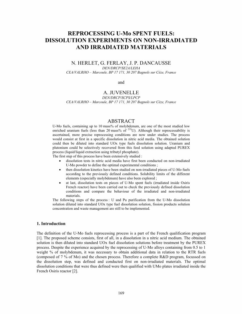
169
REPROCESSING U-Mo SPENT FUELS: DISSOLUTION EXPERIMENTS ON NON-IRRADIATED
AND IRRADIATED MATERIALS
N. HERLET, G. FERLAY, J. P. DANCAUSSE DEN/DRCP/SE2A/LEHA
CEA/VALRHO – Marcoule, BP 17 171, 30 207 Bagnols sur Cèze, France
and
A. JUVENELLE DEN/DRCP/SCPS/LPCP
CEA/VALRHO – Marcoule, BP 17 171, 30 207 Bagnols sur Cèze, France
ABSTRACT U-Mo fuels, containing up to 10 mass% of molybdenum, are one of the most studied low enriched uranium fuels (less than 20 mass% of 235U). Although their reprocessability is ascertained, more precise reprocessing conditions are now under studies. The process would consist at first in a specific dissolution in nitric acid media. The obtained solution could then be diluted into standard UOx type fuels dissolution solution. Uranium and plutonium could be selectively recovered from this feed solution using adapted PUREX process (liquid/liquid extraction using tributyl phosphate). The first step of this process have been extensively studied :
• dissolution tests in nitric acid media have first been conducted on non-irradiated U-Mo powder to define the optimal experimental conditions ;
• then dissolution kinetics have been studied on non-irradiated pieces of U-Mo fuels according to the previously defined conditions. Solubility limits of the different elements (especially molybdenum) have also been explored ;
• at last, dissolution tests on pieces of U-Mo spent fuels (irradiated inside Osiris French reactor) have been carried out to check the previously defined dissolution conditions and compare the behaviour of the irradiated and non-irradiated materials.
The following steps of the process : U and Pu purification from the U-Mo dissolution solution diluted into standard UOx type fuel dissolution solution, fission products solution concentration and waste management are still to be implemented.
1. Introduction The definition of the U-Mo fuels reprocessing process is a part of the French qualification program [1]. The proposed scheme consists, first of all, in a dissolution in a nitric acid medium. The obtained solution is then diluted into standard UOx fuel dissolution solutions before treatment by the PUREX process. Despite the experience acquired by the reprocessing of U-Mo alloys containing from 0.5 to 1 weight % of molybdenum, it was necessary to obtain additional data in relation to the RTR fuels (composed of 7 % of Mo) and the chosen process. Therefore a complete R&D program, focussed on the dissolution step, was defined and conducted first on non-irradiated materials. The optimal dissolution conditions that were thus defined were then qualified with UMo plates irradiated inside the French Osiris reactor [2].
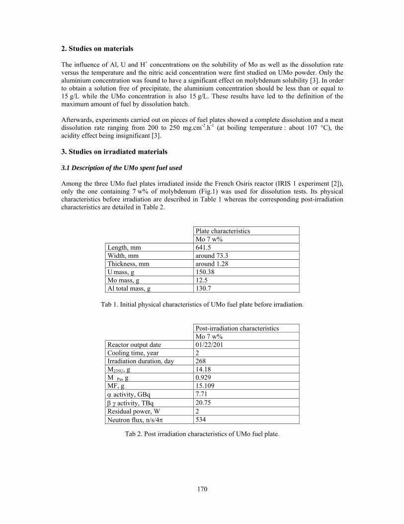
170
2. Studies on materials The influence of Al, U and H+ concentrations on the solubility of Mo as well as the dissolution rate versus the temperature and the nitric acid concentration were first studied on UMo powder. Only the aluminium concentration was found to have a significant effect on molybdenum solubility [3]. In order to obtain a solution free of precipitate, the aluminium concentration should be less than or equal to 15 g/L while the UMo concentration is also 15 g/L. These results have led to the definition of the maximum amount of fuel by dissolution batch. Afterwards, experiments carried out on pieces of fuel plates showed a complete dissolution and a meat dissolution rate ranging from 200 to 250 mg.cm-2.h-1 (at boiling temperature : about 107 °C), the acidity effect being insignificant [3]. 3. Studies on irradiated materials 3.1 Description of the UMo spent fuel used Among the three UMo fuel plates irradiated inside the French Osiris reactor (IRIS 1 experiment [2]), only the one containing 7 w% of molybdenum (Fig.1) was used for dissolution tests. Its physical characteristics before irradiation are described in Table 1 whereas the corresponding post-irradiation characteristics are detailed in Table 2.
Plate characteristics Mo 7 w% Length, mm 641.5 Width, mm around 73.3 Thickness, mm around 1.28 U mass, g 150.38 Mo mass, g 12.5 Al total mass, g 130.7
Tab 1. Initial physical characteristics of UMo fuel plate before irradiation.
Post-irradiation characteristics Mo 7 w% Reactor output date 01/22/201 Cooling time, year 2 Irradiation duration, day 268 M235U, g 14.18 M�Pu, g 0.929 MF, g 15.109 α activity, GBq 7.71 β γ activity, TBq 20.75 Residual power, W 2 Neutron flux, n/s/4π 534
Tab 2. Post irradiation characteristics of UMo fuel plate.

171
3.2. Dissolution tests 3.2.1 Description of the experiments The following operating conditions, defined after studies on non-irradiated materials were applied :
• dissolution in nitric acid medium, at boiling temperature, • initial [H+] = 5 M, • initial [Al] = 3 g/L to take into account the aluminium contribution of the structural
device supporting the plates in reactor, • recombining NOx gases, • targeted concentrations : [Al] = 15 g/L, [UMo] = 15 g/L,
First tests were conducted on small amounts of material (less than 5 cm long) in small vessels (Figure 1) whereas the last one, dedicated to validation of the operating conditions, was realized on one third of UMo plate (20 cm long) inside a five litre vessel (Figure 2).
Fig 1. Small scale dissolution vessel
Fig 2. Large scale dissolution apparatus
More over one small scale test was conducted on a cladding piece, sampled outside the core zone. Therefore, as there is no analytical interference between the aluminium coming from the cladding and the one from the core, the cladding dissolution kinetics determination was optimized. 3.2.2 Kinetics results The dissolution kinetics obtained on irradiated materials (dissolution curves on Figures 3 and 4) can be compared to the one on fuel (Figure 5) : the obtained dissolution rates, both on core and cladding, are rather similar (Table 3). Irradiation seems to have no increase on aluminium dissolution rate, contrary to previously observed phenomenon on thermally treated samples [3].
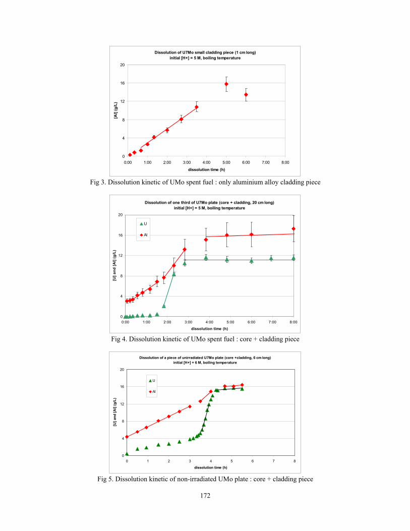
172
Dissolution of U7Mo small cladding piece (1 cm long)initial [H+] = 5 M, boiling temperature
0
4
8
12
16
20
0:00 1:00 2:00 3:00 4:00 5:00 6:00 7:00 8:00
dissolution time (h)
[Al]
(g/L
)
Fig 3. Dissolution kinetic of UMo spent fuel : only aluminium alloy cladding piece
Dissolution of one third of U7Mo plate (core + cladding, 20 cm long)initial [H+] = 5 M, boiling temperature
0
4
8
12
16
20
0:00 1:00 2:00 3:00 4:00 5:00 6:00 7:00 8:00
dissolution time (h)
[U] a
nd [A
l] (g
/L)
U
Al
Fig 4. Dissolution kinetic of UMo spent fuel : core + cladding piece
Dissolution of a piece of unirradiated U7Mo plate (core +cladding, 6 cm long)
initial [H+] = 6 M, boiling temperature
0
4
8
12
16
20
0 1 2 3 4 5 6 7 8
dissolution time (h)
[U] a
nd [A
l] (g
/L)
U
Al
Fig 5. Dissolution kinetic of non-irradiated UMo plate : core + cladding piece

173
Tests on non-irradiated materials Tests on irradiated material
Core + cladding Only cladding
Core + cladding
Temperature (°C) Boiling temperature Initial [H+] (N) 6.1 7.3 4.8 5 5 Final [H+] (N) 4.1 5.2 2.8 - 2.8 Cladding aluminium dissolution rate (mg.cm-2.h-1)
~30 32 34
Uranium dissolution rate (mg.cm-2.h-1)
195 180 185 - 192
Meat dissolution rate (mg.cm-2.h-1)
235 220 225 - 240
Tab 3. Comparison on dissolution kinetic on irradiated and non-irradiated materials. Insoluble species and solutions aging Insoluble species were especially studied during the last “validation” dissolution test conducted on one third of UMo plate. While dissolving at boiling temperature, the dissolution solution appeared to be rather clear. Then after one night cooling it became slightly cloudy. Filtration upon a 0.3 µm filter led to an amount of insoluble species representing less than 0.6 w% of the initial spent fuel introduced into the dissolution vessel. These insoluble species were found to be composed of more than 90 w% of molybdenum and aluminium. The filtrated dissolution solution was then kept inside glass flask for months. While aging it showed no evolution and remained totally clear. New filtration after one month aging (upon 0.3 µm filter) showed no significant amount of insoluble species. 4. Conclusions Although reprocessability of UMo spent fuel was ascertained, more precise reprocessing conditions were studied, mainly concerning the dissolution step. Experiments were carried out first on non-irradiated materials and then on UMo plates irradiated inside the French Osiris reactor. Provided the dissolution solutions are diluted enough to take into account the rather low solubility limit of molybdenum, clear and stable dissolution solutions can be obtained, with quite a little amount of insoluble species. Dissolution kinetics of non-irradiated and irradiated materials were found to be very similar : about 30 mg.cm-2.h-1 for cladding and 220-240 mg.cm-2.h-1 for the core. The following steps of the process: U and Pu purification from the U-Mo dissolution solution diluted into standard UOx type fuel dissolution solution, fission products solution concentration and waste management are still to be implemented. 5. References [1] J. M. Hamy, F. Huet, B. Guigon, P. Lemoine, C. Jarousse, M. Boyard, J. L Emin, « Status as of October 2003 of the French UMo group development program », 25th International Meeting on RERTR, Chicago, USA, October 5-10, 2003.
[2] F. Huet, V. Marelle, J. Noirot, P. Sacristan, P. Lemoine, « Full-sized plates irradiation with high UMo fuel loading – IRIS 1 experiment », 25th International Meeting on RERTR, Chicago, USA, October 5-10, 2003.
[3] A. Juvenelle, Transactions of International. Conference on Research Reactor Fuel Management (RRFM 03), Aix en Provence, France, March 9-12, 2003, p. 222.
174
HABOG: ONE BUILDING FOR ALL HIGH LEVEL WASTE AND SPENT FUEL IN THE NETHERLANDS.
THE FIRST YEAR OF EXPERIENCE
J. KASTELEIN and DR. H.D.K. CODÉE COVRA N.V.
P.O. Box 202, 4380 AE Vlissingen, The Netherlands
ABSTRACT COVRA N.V. operates a site for the treatment and storage of all types of radioactive waste in the Netherlands. In 2003 the facility for storage of high level reprocessing waste and spent fuel from research reactors came into operation. The building is a piece of art. In a technical sense, as it was designed to withstand events such as earthquakes, flooding and aircraft crashes; but also in a literal sense, its provocative design was meant to evoke a discussion about the public aspects of radioactive waste management. Construction took place from 1998 until 2002 and active operation at the end of 2003. The technical experience is positive. Nine MTR2 containers with spent fuel were treated and stored and 28 canisters with vitrified reprocessing waste were stored. The experience with the communicative function is positive also. Since the opening of the facility, the amount of visitors to the COVRA site more than doubled.
1. Introduction COVRA N.V., the Central Organisation for Radioactive Waste, manages all radioactive waste produced in the Netherlands. Its statutory task is to execute the Dutch policy on the management of radioactive waste. This policy includes the long-term storage of all types of waste above ground for a period of at least a hundred years. COVRA treats and stores all categories of radioactive waste, including TENORM, spent fuel from research reactors and vitrified waste from reprocessing, on a specially designed site of 25 ha at the industrial area of Vlissingen-Oost, [1,2]. Direct disposal is not yet feasible in the Netherlands. Deep geologic disposal has not found general public acceptance and the small quantities involved prohibit an environmentally sound and economically feasible construction of the repository. However, the small volumes of waste do not require an immediate final solution. The small quantities of waste can easily be isolated from the environment by storing them for a long time in buildings. The natural decay during this period reduces the radioactivity, notably for the low and medium level waste. The long-term storage also buys time for the development of future international or regional disposal solutions, or radically new techniques to remove the hazardous constituents. Moreover, a capital growth fund has been established to use the available time to build up sufficient financial resources to soundly construct, operate and finally close a repository. The choice for long-term storage above ground is not a “wait and see” option. This follows directly from the integral parts of the policy: the establishment of the capital growth fund and the transfer of the ownership of the waste to COVRA. This policy does not leave the burden of waste generated today to future generations. Only the execution of the disposal is left as a task for the future. 2. Safety of the design
For the long-term storage of high-level radioactive waste above ground, the treatment and storage building, the so-called HABOG (the Dutch acronym), was developed. Safety was a matter of great
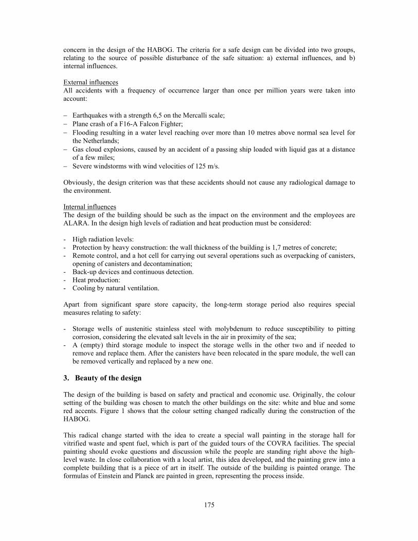
175
concern in the design of the HABOG. The criteria for a safe design can be divided into two groups, relating to the source of possible disturbance of the safe situation: a) external influences, and b) internal influences. External influences All accidents with a frequency of occurrence larger than once per million years were taken into account: − Earthquakes with a strength 6,5 on the Mercalli scale; − Plane crash of a F16-A Falcon Fighter; − Flooding resulting in a water level reaching over more than 10 metres above normal sea level for
the Netherlands; − Gas cloud explosions, caused by an accident of a passing ship loaded with liquid gas at a distance
of a few miles; − Severe windstorms with wind velocities of 125 m/s. Obviously, the design criterion was that these accidents should not cause any radiological damage to the environment. Internal influences The design of the building should be such as the impact on the environment and the employees are ALARA. In the design high levels of radiation and heat production must be considered: - High radiation levels: - Protection by heavy construction: the wall thickness of the building is 1,7 metres of concrete; - Remote control, and a hot cell for carrying out several operations such as overpacking of canisters,
opening of canisters and decontamination; - Back-up devices and continuous detection. - Heat production: - Cooling by natural ventilation. Apart from significant spare store capacity, the long-term storage period also requires special measures relating to safety: - Storage wells of austenitic stainless steel with molybdenum to reduce susceptibility to pitting
corrosion, considering the elevated salt levels in the air in proximity of the sea; - A (empty) third storage module to inspect the storage wells in the other two and if needed to
remove and replace them. After the canisters have been relocated in the spare module, the well can be removed vertically and replaced by a new one.
3. Beauty of the design The design of the building is based on safety and practical and economic use. Originally, the colour setting of the building was chosen to match the other buildings on the site: white and blue and some red accents. Figure 1 shows that the colour setting changed radically during the construction of the HABOG. This radical change started with the idea to create a special wall painting in the storage hall for vitrified waste and spent fuel, which is part of the guided tours of the COVRA facilities. The special painting should evoke questions and discussion while the people are standing right above the high-level waste. In close collaboration with a local artist, this idea developed, and the painting grew into a complete building that is a piece of art in itself. The outside of the building is painted orange. The formulas of Einstein and Planck are painted in green, representing the process inside.
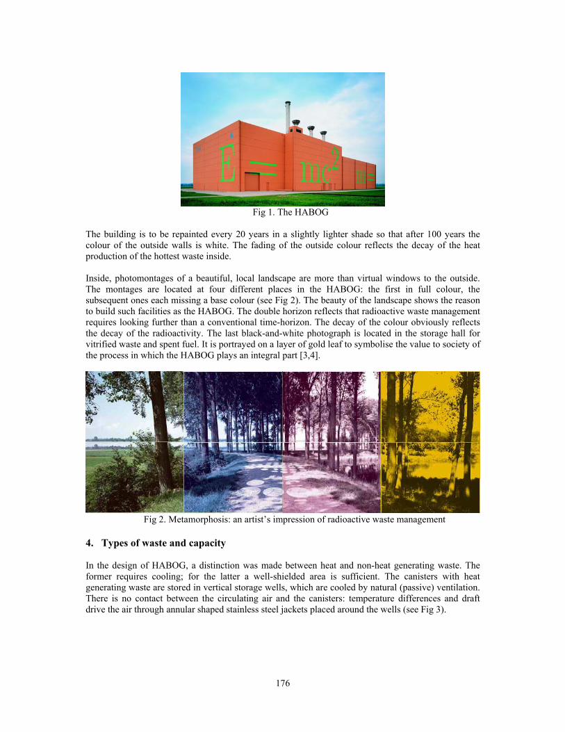
176
Fig 1. The HABOG
The building is to be repainted every 20 years in a slightly lighter shade so that after 100 years the colour of the outside walls is white. The fading of the outside colour reflects the decay of the heat production of the hottest waste inside.
Inside, photomontages of a beautiful, local landscape are more than virtual windows to the outside. The montages are located at four different places in the HABOG: the first in full colour, the subsequent ones each missing a base colour (see Fig 2). The beauty of the landscape shows the reason to build such facilities as the HABOG. The double horizon reflects that radioactive waste management requires looking further than a conventional time-horizon. The decay of the colour obviously reflects the decay of the radioactivity. The last black-and-white photograph is located in the storage hall for vitrified waste and spent fuel. It is portrayed on a layer of gold leaf to symbolise the value to society of the process in which the HABOG plays an integral part [3,4].
Fig 2. Metamorphosis: an artist’s impression of radioactive waste management
4. Types of waste and capacity In the design of HABOG, a distinction was made between heat and non-heat generating waste. The former requires cooling; for the latter a well-shielded area is sufficient. The canisters with heat generating waste are stored in vertical storage wells, which are cooled by natural (passive) ventilation. There is no contact between the circulating air and the canisters: temperature differences and draft drive the air through annular shaped stainless steel jackets placed around the wells (see Fig 3).
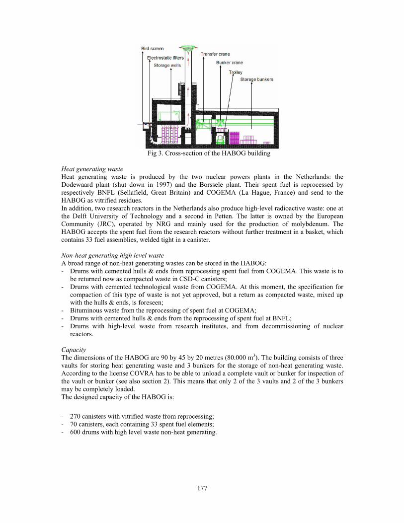
177
Fig 3. Cross-section of the HABOG building
Heat generating waste Heat generating waste is produced by the two nuclear powers plants in the Netherlands: the Dodewaard plant (shut down in 1997) and the Borssele plant. Their spent fuel is reprocessed by respectively BNFL (Sellafield, Great Britain) and COGEMA (La Hague, France) and send to the HABOG as vitrified residues. In addition, two research reactors in the Netherlands also produce high-level radioactive waste: one at the Delft University of Technology and a second in Petten. The latter is owned by the European Community (JRC), operated by NRG and mainly used for the production of molybdenum. The HABOG accepts the spent fuel from the research reactors without further treatment in a basket, which contains 33 fuel assemblies, welded tight in a canister. Non-heat generating high level waste A broad range of non-heat generating wastes can be stored in the HABOG: - Drums with cemented hulls & ends from reprocessing spent fuel from COGEMA. This waste is to
be returned now as compacted waste in CSD-C canisters; - Drums with cemented technological waste from COGEMA. At this moment, the specification for
compaction of this type of waste is not yet approved, but a return as compacted waste, mixed up with the hulls & ends, is foreseen;
- Bituminous waste from the reprocessing of spent fuel at COGEMA; - Drums with cemented hulls & ends from the reprocessing of spent fuel at BNFL; - Drums with high-level waste from research institutes, and from decommissioning of nuclear
reactors. Capacity The dimensions of the HABOG are 90 by 45 by 20 metres (80.000 m3). The building consists of three vaults for storing heat generating waste and 3 bunkers for the storage of non-heat generating waste. According to the license COVRA has to be able to unload a complete vault or bunker for inspection of the vault or bunker (see also section 2). This means that only 2 of the 3 vaults and 2 of the 3 bunkers may be completely loaded. The designed capacity of the HABOG is:
- 270 canisters with vitrified waste from reprocessing; - 70 canisters, each containing 33 spent fuel elements; - 600 drums with high level waste non-heat generating.
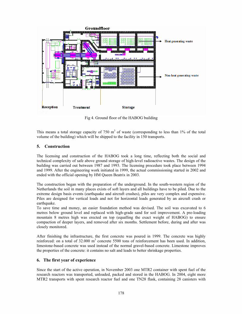
178
Fig 4. Ground floor of the HABOG building
This means a total storage capacity of 750 m3 of waste (corresponding to less than 1% of the total volume of the building) which will be shipped to the facility in 150 transports. 5. Construction
The licensing and construction of the HABOG took a long time, reflecting both the social and technical complexity of safe above ground storage of high-level radioactive wastes. The design of the building was carried out between 1987 and 1993. The licensing procedure took place between 1994 and 1999. After the engineering work initiated in 1999, the actual commissioning started in 2002 and ended with the official opening by HM Queen Beatrix in 2003. The construction began with the preparation of the underground. In the south-western region of the Netherlands the soil in many places exists of soft layers and all buildings have to be piled. Due to the extreme design basis events (earthquake and aircraft crashes), piles are very complex and expensive. Piles are designed for vertical loads and not for horizontal loads generated by an aircraft crash or earthquake. To save time and money, an easier foundation method was devised. The soil was excavated to 6 metres below ground level and replaced with high-grade sand for soil improvement. A pre-loading mountain 8 metres high was erected on top (equalling the exact weight of HABOG) to ensure compaction of deeper layers, and removed after six months. Settlement before, during and after was closely monitored. After finishing the infrastructure, the first concrete was poured in 1999. The concrete was highly reinforced: on a total of 32.000 m3 concrete 5500 tons of reinforcement has been used. In addition, limestone-based concrete was used instead of the normal gravel-based concrete. Limestone improves the properties of the concrete: it contains no salt and leads to better shrinkage properties.
6. The first year of experience Since the start of the active operation, in November 2003 one MTR2 container with spent fuel of the research reactors was transported, unloaded, packed and stored in the HABOG. In 2004, eight more MTR2 transports with spent research reactor fuel and one TN28 flask, containing 28 canisters with
179
vitrified residues from the reprocessing of spent fuel from the nuclear power plant Borssele were handled in HABOG. The complete cycle for the treatment of a MTR2 transport container, loaded with 33 spent fuel elements from research reactors, takes about 5 days. For preparation, testing of the equipment and cleaning the installation another 5 days are needed, which makes in total 10 working days per campaign. Up to now, no contamination has been detected in the hotcell. Even the gripper, which takes the basket out of the flask, has not been contaminated. A cycle for the treatment of a TN28 transport flask, loaded with 28 canisters with vitrified waste from reprocessing, takes about 15 working days including reception and return of the transport flask. The delivery and product documentation of the waste is checked by COVRA at the La Hague plant. After the control of documentation, the canisters are physically checked before loading into the flask. This check consists of a visual control, contamination and a dose-rate control. After reception of the canisters, the same controls are carried out during the unloading of the canisters at COVRA. After the unloading of the first TN28 flask with vitrified waste, a dose rate of 5 microSievert/h was measured, due to scattering at the air inlet. In the design it was foreseen, based on calculations, that the expected dose rate would be 17 microSievert/h. The value could be penalising for the dose rate limit at the boundary of the site. During office hours, four operators operate the facility. In addition to their operational tasks, they are also responsible for a significant part of the first-line maintenance, the equipment testing and the cleaning of the facility. In the first year of operation only minor problems occurred: - Some small problems in the software of control system, which have been fixed; - Power supply rails of the trolley had to be replaced; - The electrostatic filters that treat the incoming cooling air cause false alarms and are not operating
to our satisfaction, due to moisture during fog and rain; - The guiding of one of the heavy shielding doors is not correct. The guiding mechanism based on
chains is replaced by one based on rollers, but the rollers cause some problems as well. Experience with the communicative function of the building is also very positive. People are really intrigued by the facility. This results in the wish to come and visit the facilities. COVRA has always welcomed visitors, but now a complete new group of society shows interest. The art function is a good start for communication. Since the opening in 2003 the amount of visitors more than doubled as compared with earlier years. 7. The future
The storage of the high-level radioactive waste is foreseen for at least 100 years. The period is divided in an active and a passive operation phase. During the active operation phase, which in principle will end in 2015, the building is loaded. In the period between 2015 and 2100, the passive period, no activities occur in building. The central control room at the COVRA site does surveillance. After this passive period, it has to be decided to unload the storage facility and to bring the waste to a final repository or use new techniques to process and/or store the waste. The storage capacity and duration of the active period was based on the operational life spans of the nuclear power plants (Borssele and Dodewaard) and the research reactors in the Netherlands. Dodewaard was shut down in 1997 and the closure of Borssele was originally planned at the end of 2003. However, after construction of the HABOG, politics decided to keep Borssele in operation as long as safety and economics permit. This means that the storage capacity for reprocessing waste is likely not to be sufficient and need to be increased in the future. The modified HABOG should be ready in about 10 years from now.

180
8. Conclusions
In the Netherlands a multipurpose facility for high-level radioactive waste is in operation. Vitrified reprocessing waste and spent fuel from research reactors can safely be handled and stored for a period of at least 100 years. The first year of experience shows that, the facility operates very well. Radiation levels inside and outside the building as well as the temperatures in the storage vault are as expected. 9. References 1. H.D.K. Codée, “Controlled Containment, Radioactive Waste Management in the Netherlands”,
Proceedings WM’02, February 23-28, 2002, Tucson, AZ.
2. H.D.K. Codée, “Radioactive Waste Management in the Netherlands; A Practical Solution in Full Operation”, Proceedings IAEA International Conference on the Safety of Radioactive Waste Management, Cordoba, Spain, March 13-17, 2000. STI/PUB/1094, International Atomic Energy Agency (2000).
3. H.D.K. Codée, “Give the public something, something more interesting than radioactive waste”, Proceedings WM’03, February 23-27, 2003, Tucson, AZ.
4. H.D.K. Codée, “The wrong story”, ENS, PIME 2005, 13 – 16 February 2005, Paris, France.
181
SPENT FUEL FROM THE FINNISH TRIGA RESEARCH REACTOR IN THE SURROUNDINGS OF BWR SPENT FUEL
FINAL DISPOSAL REPOSITORY. SAFETY ASSESSMENT AND COMPARISON TO THE RISKS OF THE BWR FUEL
S. E. J. SALMENHAARA, H.O. NORDMAN and M.S. ANTTILA VTT Processes
Technical Research Centre of Finland (VTT) Otakaari 3 A, P.O. Box 1608, FIN-02044 VTT (Espoo), Finland
ABSTRACT The Finnish Triga reactor, a 250 kW research reactor, has been in operation since 1962. According to the current operating license of our reactor we have to achieve a binding agreement between our Research Centre and the domestic Nuclear Power Companies about the possibility to use the Olkiluoto final disposal facility for our spent fuel. Naturally there is also the possibility to make an agreement with USDOE about the return of our spent fuel back to USA. In case of the domestic final disposal solution the main safety aspects, which have to be analyzed and compared to the spent fuel coming from the nuclear power plants, are the criticality safety, the solubility of the fuel (UZrHx) to water and the existence of some moving and long-lived radioactive isotopes. The criticality safety calculations show that it is possible to load safely all the TRIGA fuel elements in one heavy final disposal canister. A simple safety analysis for the Triga fuel has been carried out in order to evaluate the long term risks of the final disposal. For the analysis a few scenarios from the TILA-99 safety assessment have been chosen. These scenarios will give a good picture of the potential risk of disposed Triga fuel compared to BWR fuel. TILA-99 safety assessment includes about 100 calculated different scenarios for the spent fuel so it’s not reasonable to calculate them all for the Triga fuel. The main result is that the risks from the final disposal of Triga fuel are minor compared to BWR mainly due to smaller activity inventories.
1. Introduction The FiR 1 reactor, a 250 kW Triga reactor, has been in operation since 1962. The main purpose to run the reactor has been lately the Boron Neutron Capture Therapy (BNCT). The BNCT work dominates the current utilization of the reactor: three or four days per week for BNCT purposes and the rest for other purposes such as the neutron activation analysis and isotope production. According to our current operating license we have to achieve this year (2005) a binding agreement between VTT and the domestic Nuclear Power Plant Companies about the possibility to use the Olkiluoto final disposal facility for our spent fuel. In this case we can continue the operation of the reactor as long as there is reasonable work to do and the funding is in order [1]. Naturally we can also make an agreement with the USDOE. Especially after the announcement of the coming extension of ten years of the return policy the US alternative is nearly equal compared to the domestic one. For later negotiations aiming to the binding agreement about the domestic final disposal we are making safety studies about the long term behaviour of the spent TRIGA fuel in the final disposal surroundings. The main safety aspects, which have to be analyzed and compared to the spent fuel coming from nuclear power plants, are the criticality safety, the solubility of the fuel (UZrHx) in water and the existence of some moving and long-lived radioactive isotopes.
For the final repository the spent fuel will be encapsulated in airtight copper canisters and situated in the bedrock at a depth of 500 m. The safety of this deep underground repository is based on multiple

182
natural and engineered barriers. Each canister contains 12 normal BWR fuel assemblies. The present concept for 127 Triga fuel elements is that the elements will be loaded in special containers, which have the same outer dimensions as the BWR fuel assemblies. Figure 1 describes the heavy final disposal canister.
The Triga fuel is much more reactive compared to the spent BWR fuel and therefore the Triga fuel can not be situated so tightly in the final disposal canister. The Triga fuel containers will be situated in the outer zone of the canister and the inner zone will be left empty. In practice the empty positions will be loaded with dummy assemblies made of cast iron. The criticality safety calculations show, however, that it is possible to load safely all the TRIGA fuel elements in one final disposal canister [2]. In this study the potential risks associated with final disposal of Triga fuel is in this study analysed on the basis of comprehensive safety assessment TILA-99 [3].
Posiva Oy Posiva Oy
Fig 1. Final disposal canister
2. Fuel to be disposed off The canister containing Triga fuel differs from Olkiluoto BWR fuel in several ways: - The amount of uranium is only 1.3 % of the uranium contents of the BWR fuel from Olkiluoto. - The amount of zirconium is 260 kg in the Triga canister compared to 1000 kg in a BWR canister. - The Triga fuel in the canister is an alloy of uranium (27.5 kg), zirconium (260 kg) and hydrogen
(~ 3 kg). - The Triga canister contains also 45 kg of graphite reflectors at both ends of the rods.
Graphite is considered to be hazardous for copper in some circumstances. It doesn’t cause any difference, however, compared to BWR fuel, when forming the scenarios for the safety analyses, as the copper canister is assumed to be damaged as a result of outside corrosion processes.
The inventories of radionuclides and stable isotopes are the most important differences between Triga and BWR fuels. The inventory of Triga fuel has been calculated with a 3-dimensional MCNP-model [4] and the inventory of Olkiluoto with ORIGEN-model [5]. The activity inventory of a canister containing 127 rods of Triga fuel (steel cladding assumed) has been compared to that of a canister containing 12 elements of Olkiluto BWR fuel in Table 1.

183
Nuclide Triga (Bq) Olkiluoto (Bq) Nuclide Triga (Bq) Olkiluoto (Bq)
H-3 1.0⋅1011 - Np-237 1.1⋅108 1.2⋅1011 C-14 3.3⋅108 7.3⋅1010 Cl-36 4.4⋅107 3.1⋅109 Pu-239 2.8⋅1011 2.9⋅1013 Se-79 6.0⋅108 3.5⋅1010 Pu-240 8.8⋅1010 4.1⋅1013 Sr-90 6.5⋅1013 2.9⋅1015 Pu-242 1.0⋅107 1.7⋅1011 Zr-93 3.6⋅109 2.1⋅1011 Tc-99 2.0⋅1010 1.1⋅1012 U-238 3.5⋅108 2.5⋅1010 Pd-107 2.9⋅107 1.1⋅1010 U-234 1.1⋅1010 * 2.1⋅1011 Sn-126 5.5⋅108 6.9⋅1010 I-129 3.4⋅107 2.8⋅109 U-235 4.5⋅108 2.4⋅109 Cs-135 1.6⋅109 5.0⋅1010 Cs-137 6.9⋅1010 4.4⋅1016
Tab 1. Activity inventories of a canister containing Triga fuel (127 rods with steel cladding, burnup 35 MWd/kgU) and of a canister containing Olkiluoto BWR fuel (12 elements 2.14 tU, burnup 36 MWd/kgU ). Inventories at the closure of the repository (30 yr cooling time); contribution of short lived are added to some daughters. * U-234 inventory of Triga fuel is assumed to be 30 times that of U-238 which roughly coincides with the effect of isotopic enrichment.
It can be seen directly from Table 1 that the inventory of the Triga fuel is small compared to the Olkiluoto BWR inventory. Thus it’s quite evident that the canister containing Triga fuel can’t cause greater risk than the BWR fuel. There is one difference, the relatively higher inventory of U-235 (enrichment 20 %) and U-234 compared to U-238 in the Triga fuel. When applying the solubility limit of uranium (as it is always the case) the concentration of U-234 and U-235 in water inside the canister will be higher than in the case of BWR fuel. The amount of stable isotopes in the Triga fuel has been estimated from MCNP-model results separately. This data is important when applying the solubility limit inside the canister.
3. Scenarios to be analysed The four scenarios to be analysed are from the TILA-99 safety assessment. The first two scenarios are the so called base cases: - SH-sal50: Initially a small hole in the canister (5 mm2), saline groundwater (present at Olkiluoto)
and median flow rate of groundwater. Fuel matrix is assumed to degrade within about one million years.
- DC-ns50: Canister suddenly severely damaged after 10 000 years, non-saline ground water (due to land uplift) and median flow rate of groundwater. Fuel matrix is assumed to degrade within about one million years.
In order to find out the effect of some extreme conditions, the following two sensitivity analyses from TILA-99 have been chosen: - DC-vhfsal: Canister suddenly severely damaged after 10 000 years, saline ground water and very
high flow rate of groundwater. Fuel matrix is assumed to degrade within about one million years. - DC-vhfsalficm: Canister suddenly severely damaged after 10 000 years, saline ground water and
very high flow rate of groundwater. Fuel matrix is assumed to degrade evenly between 10 000…20 000 years. (ficm an acronym from “finish instant coffee model”).

184
The comparison of the two very high flow and saline chemistry scenarios will reveal the effect of the differences of Triga and BWR fuel material. The other data (diffusion coefficients etc.) for calculations including instant release fraction from fuel (e.g. 6 % for iodine) are from TILA-99. 4. Results
The total dose rates and doses from three most important nuclides from Triga fuel and BWR fuel are presented in Table 2. The relations between doses from Triga fuel and BWR fuel are presented in Table 3.
tmax (yr)
max (Sv/yr)
1st nuclide
(Sv/yr)
2nd nuclide
(Sv/yr)
3rd nuclide
(Sv/yr)
Median flow scenarios
SH-sal50 - Ol. BWR - Triga
8.4·105
8.6·105
1.7·10-9
3.7·10-11
I-129 I-129
1.3·10-9
1.6·10-11
Cs-135 Sn-126
3.6·10-10
1.3·10-11
C-14 Cs-135
1.3·10-10
1.1·10-11
DC-ns50 - Ol. BWR - Triga
1.1·104
1.1·104
3.2·10-8
3.8·10-10
I-129 I-129
2.9·10-8
3.6·10-10
Sn-126 Se-79
5.7·10-9
7.1·10-11
C-14 Pa-231
4.4·10-9
4.8·10-11 High flow saline chemistry scenarios (vhfsalficm; fuel degraded in 10 000 years)
DC-vhfsal - Ol. BWR - Triga
6.1·105
4.9·105
2.7·10-6
1.3·10-7
Ra-226 Ra-226
2.7·10-6
1.2·10-7
I-129 Pa-231
2.1·10-7
7.6·10-9
Pa-231 I-129
4.2·10-8
2.5·10-9
DC-vhfsalficm - Ol. BWR - Triga
2.9·105
2.7·105
7.1·10-6
3.6·10-7
Ra-226 Ra-226
7.0·10-6
3.5·10-7
I-129 Pa-231
2.3·10-7
7.7·10-9
Pa-231 I-129
4.2·10-8
2.8·10-9
Tab 2. Maximum indicative dose rates and the most important nuclides
Scenario Relation of doses
BWR fuel/Triga fuel
Dose rate from Triga fuel (Sv/yr)
SH-sal50 46 3.7⋅10-11
DC-ns50 84 3.8⋅10-10
DC-vhfsal 21 1.3⋅10-7
DC-vhfsalficm 20 3.6⋅10-7
Tab 3. Relation between doses from Triga fuel and BWR fuel in the calculated four scenarios From the Table 2 it can be seen, that in the base cases (SH-sal50 and DC-ns50), where I-129 is dominating the dose rate is proportional to the inventories in Table 1. Nuclide Pa-231 is more important in Triga fuel as the relative amount of parent nuclide U-235 is higher (enrichment 20 % in Triga fuel).
185
The most important and interesting result is that in the high flow scenario (DC-vhfsalficm), where the fuel is assumed to degrade within 10 000 years, the dose rate from the Triga fuel is 3.6⋅10-7 Sv/yr. This rate is lower than the dose rate (2.7⋅10-6 Sv/yr) from Olkiluoto BWR fuel in DC-vhflowsal scenario, where the degradation of fuel is assumed to last about one million years. Thus the potential faster degradation of Triga fuel (UZrHx alloy) is of minor importance.
5. Conclusions
According to the results presented in this work, the doses resulting from the final disposal canister of Triga fuel are lower than from the canister of the Olkiluoto BWR fuel and no safety problems have appeared during the study. The comparison has been made between one BWR fuel canister and the only Triga canister. In reality there will be more than 1000 BWR and PWR canisters in the final disposal repository and only one Triga fuel canister. The results are important for the negotiations between our Research Centre and the company Posiva Oy, which is taking care of the whole final disposal arrangements of the spent fuel from the Finnish nuclear power plants. Also the authorities are interested in the results, because they follow our research work connected to the decommissioning plans of our reactor.
6. References
[1] S. Salmenhaara, Trans. Int. Conf. Research Reactor Fuel Management (RRFM 2004), München, Germany, March 21-24, 2004, p. 231.
[2] Anttila. M. 2001. The criticality safety calculations for final disposal of Fir 1 (Triga) fuel. VTT Processes. Memorandum 28.10.2001. (In Finnish)
[3] Vieno, T. & Nordman, H. 1999. Safety assessment of spent fuel disposal in Hästholmen, Kivetty, Olkiluoto and Romuvaara TILA-99. POSIVA 99-07.
[4] D.I. Poston & H.R. Trellue, User’s Manual, Version 2.0 for MONTEBURNS, Version 1.0, LA-UR-99-4999 (September 1999).
[5] ORIGEN 2.1 1991, Isotope Generation and Depletion Code, Matrix Exponential Method. RSIC Computer Code Collection CCC-371 (Revised August 1991).

186
UPDATE ON NAC’S TRANSPORTATION PROJECTS
Catherine Anne and John Patterson Site Transportation Services, NAC International
3930 E. Jones Bridge Road, Norcross, GA 30092, USA
ABSTRACT The Global Threat Reduction Initiative (GTRI) was announced in early 2004 by then U.S. Secretary of Energy Spencer Abraham and was reinforced by an international meeting in Vienna in September 2004 of countries supporting non- proliferation efforts. Under GTRI, the Foreign Research Reactor Program (FRR) will continue and irradiated fuel shipments under the Russian Research Fuel Return Program (RRRFR) will begin. These programs will result in a projected increase in research reactor shipments in the coming years. NAC owns and operates a fleet of eight NAC-LWT casks, which can transport up to 42 MTR fuel elements each. For the past 30 years, NAC has been supporting the Department of Energy with non-proliferation initiatives. Our teams have loaded casks in more than 25 foreign countries. Recent incidents of terrorism and ongoing threats have confirmed the necessity to ensure the security of high-enriched uranium and remove it from sensitive locations. Tremendous government efforts were initiated in 2004 in order to execute intra-governmental agreements for reactor conversion and material removal. As a result of these agreements, NAC will continue to provide its cask lease and transportation services to the Department of Energy. We expect to see very challenging shipments in the coming years. We are committed to these non-proliferation efforts as well as meeting our commercial customers’ needs for transportation of irradiated fuel. The recent acquisition of NAC by USEC Inc. strengthens NAC’s resources and joins NAC with a corporation with a strong non-proliferation orientation as the U.S. Government’s Executive Agent under the highly successful U.S. - Russian Megatons to Megawatts program. This presentation summarizes our planned activities for the coming years with respect to GTRI initiatives.
1. Introduction
Last May the U.S. Secretary of Energy launched a comprehensive Global Threat Reduction Initiative (GTRI) to secure and remove high-risk nuclear and radiological materials that continue to pose a threat to the United States and the international community. In order to achieve this, the Secretary has directed the National Nuclear Security Administration (NNSA) to consolidate and accelerate the department’s nuclear material removal efforts. NNSA’s Office of Global Threat Reduction is responsible for major non-proliferation programs, including the Foreign Research Reactor Program (FRR) and the Russian Research Reactor Fuel Return Program (RRRFR). These programs involve a significant number of spent nuclear fuel shipments from research reactors around the world back to the originating countries – the United States and Russia. A related effort applying to U.S. research reactors has been initiated to effect conversion of remaining HEU cores to LEU material, and to more expeditiously return spent fuel from on-site storage at research reactors to DOE storage sites. NAC has been supporting the U.S. Department of Energy for the last 30 years in the removal of sensitive materials from various countries. In addition, NAC services U.S. commercial reactors by providing transport of small numbers of PWR and BWR pins for post irradiation examination as well as shipment of irradiated materials in connection with facility decommissioning. This paper will evaluate the potential demand for transportation services including support to these key programs:

187
2. FRR Program Program Dynamics In November 2004, the U.S. Secretary of Energy announced the extension of the FRR program until May 2019 for fuel irradiated prior to May 2016 expanding candidate fuel returns. Historically, the FRR program has executed three to four consolidated shipments per year averaging five to six casks per shipment. However, several reactors that have provided large fuel throughputs have or will shut down in the near term. In our judgment, beyond the two or three coming years, the combined effects of the extension of the program duration (allowing more flexibility in return date), the shutdown of major reactors, and the increased emphasis from GTRI will mostly cancel themselves but in total will result in a somewhat reduced demand yielding a reduced shipment rate or a similar rate with reduced casks per shipment. Other Than High Income (OTHI) Country Perspective The Secretary’s GTRI initiative has placed added emphasis on achieving the objectives of the FRR program. As a result, discussions have resumed with many OTHI country reactor operators utilizing HEU cores regarding alternatives that might not previously have been available to them (i.e. funding for replacement of HEU cores with LEU fuel). If these efforts are successful and all the OTHI countries operating HEU reactors participate in the return program, a total of around 600 MTR fuel elements representing approximately 17 cask loads and 400 TRIGA fuel elements representing two to four casks loads would be shipped to the United States. In addition, a few shipments from OTHI countries operating LEU fuel elements should be expected. However, the number of shipments is expected to be lower than historical levels as a large effort has already been completed during the first seven years of the program implementation, and a number of the participating reactors have ceased operation. High Income (HI) Country Perspective During the next three years a significant number of fuel elements from HI countries are scheduled for delivery at Savannah River Site: The European Commission has decided to return part of the U.S.-origin fuel to the United States from the Nuclear Research Group (NRG) in Petten, The Netherlands. One to two shipments should be completed in 2005. Several months ago, Studsvik’s management in Sweden decided to shut down their reactor. Approximately 500 fuel elements remaining on the site will be returned to the United States in the next three years. Also, as the replacement OPAL reactor comes on line in Australia, ANSTO will ship the remaining irradiated fuel from HIFAR reactor (about 500 fuel elements) back to the United States. After this very active period, the yearly average number of shipments is expected to be lower than historical levels unless other reactors are shut down or revise their spent fuel management policy. 3. RRRFR Program The Russian Research Reactor Fuel Return (RRRFR) is a cooperative effort of the United States, the Russian Federation and the International Atomic Energy (IAEA) to repatriate Russian fresh and spent nuclear fuel from research reactors operating with Russian origin fuel. Under this agreement close to 20 countries are eligible to receive financial and technical assistance from the United States and IAEA in order to ship their fresh and spent research reactor fuel to Russia for safe and secure management. While fresh HEU fuel shipments have been successfully performed, spent nuclear fuel shipments present a more complex technical challenge due to the nature of the fuel, casks and certifications needed, extended period since shipments were conducted and relative inexperience of participating reactor operators. After several years of planning, they are expected to start shortly. The RRRFR is a very challenging program as about 15,000 fuel elements representing many different fuel designs are targeted to be returned to Russia by 2010. More than 80% of the fuel is enriched to greater than 20% Uranium-235. The candidate reactors are spread among three continents: Europe, Asia and Africa. The existing fleet of Russian SNF transportation casks (the TUK-19) for research

188
reactors has a very limited capacity of four fuel elements per cask. In order to achieve the goal to repatriate the 15,000 fuel elements by 2010, additional cask types will need to be committed to the program. This has resulted in a program to certify the NAC-LWT cask fleet for the various Russian fuel forms. The NAC-LWT was selected because of its capacity and very flexible loading system, combined with the fact that NAC-LWT Cask has been previously analyzed and licensed for Russian fuel forms during the shipment of Iraqi and Georgian spent fuel. Additionally, in connection with the Iraq campaign, a total of six NAC-LWT casks have been successfully unloaded at the Mayak facility. We believe that upon completion of the licensing effort, the capacity and adaptability of the NAC-LWT cask fleet can easily support two yearly shipment campaigns for the Russian Program while continuing supporting the FRR shipments. Excluding the Vinca fuel in Serbia Montenegro, which represents approximately 8,000 fuel elements and which utilizes an atypical smaller size fuel element, the RRRFR Spent Fuel Program represents around 280 cask loads to be shipped to Mayak (assuming an average of 25 fuel elements per cask). Considering the extended sea and/or land shipment duration from the reactor sites to Mayak, program management will be extremely challenging. Selection of the most efficient routes and optimum casks for each facility depending of the type and number of fuel elements, facility infrastructure, shipment combination with casks originated from different countries and selection of transport mode will be key for the success of the Program. 2. NAC’s Fleet/Equipment/Capacities/Capabilities relative to RRRFR utilization
NAC owns and operates a fleet of eight NAC-LWT casks capable of transporting up to 336 MTR type fuel elements within a single shipment. The NAC-LWT is licensed by the U.S. Nuclear Regulatory Commission (NRC) and also by the U.S. Department of Transportation (DOT) for international shipments. It has received validation by more than 20 foreign countries. The NAC-LWT cask is a very flexible cask licensed for various contents such as MTR and TRIGA fuel elements, PWR and BWR fuel assemblies or rods and other types of research fuel rods. It also has been analyzed for Russian IRT-2, EK-36, EK-10, and EK-NU, and Tammuz fuel assemblies. Last January, a revised Certificate of Compliance was issued by the NRC to extend the NAC-LWT certificate for five additional years (until February 2010) and to update the certificate in compliance with TSR-1 (IAEA 96). While the adoption of the TSR-1 regulations by the U.S. NRC (implemented October 2004) allowed a three-year time period for compliance, NAC immediately upgraded the certification and will perform the first shipment under the –96 certificate this spring. NAC also has a fleet of five NLI-1/2 casks than can be utilized for fuel shipments as specified in its existing certificate, or if authorized by special arrangement. The NLI-1/2 is the predecessor cask to the NAC-LWT and duplicates much of its loading flexibility, procedures, and capacity. The unique loading flexibility of the NAC-LWT (an extensive complement of equipment has been designed and manufactured to facilitate fuel transfer in facilities with limited pool and handling infrastructure) permits expedient adaptation of the cask to facilities such as the RRRFR participants that may not have performed a spent fuel shipment in their lifetime. This loading flexibility is also a key element in meeting the requirements of the RRRFR program as equipment design to resolve cask-loading interfaces can result in a long and costly process. NAC’s 20 years of experience in international shipments of spent nuclear fuel by road, rail, sea and air, offer substantial benefit to the program’s efficiency and safe execution. 4. Near Term Perspective (coming year) NAC will continue substantial involvement in the return shipments of SNF under the FRR Program. The European Commission has awarded a contract to NAC to ship back to Savannah River Site up to
189
700 HEU fuel elements. A first shipment of five NAC-LWT casks from the Nuclear Research Group’s (NRG) Petten reactor will take place this year. In 2004, NAC received a contract from Reaktorinstitut Graz, Austria to ship the HEU and LEU Argonaut plates back to Savannah River Site using one NAC-LWT Cask. We are expecting to perform the shipment in 2005 in combination with another shipment from the Mediterranean Sea. For the OTHI countries, NAC is the designated DOE transportation contractor. NAC provided technical support to the Department of Energy earlier this year to assess research reactor spent nuclear fuel transportation located in Europe and South America as these reactors are planning to utilize the opportunity to return their HEU fuel elements to the United States in the near future. Another key element for spent nuclear fuel element transportation is the licensing activity. The casks are licensed for detailed content and any material deviation is subject to a license amendment. Obtaining a license amendment can be a very long process especially for international shipments as more than one Competent Authority is involved in the process. In 2005, NAC will support significant licensing efforts for the FRR and RRRFR Programs. NAC will prepare a license amendment to accommodate some Australian fuel elements from HIFAR with a design for a modified basket. Also, the NAC-LWT has previously been licensed to transport Russian Origin fuel types when NAC performed a shipment of Russian fuel from Iraq back to Mayak in 1993 and from Georgia in 1998. As mentioned above, NAC has been contracted to perform fuel analysis in order to submit a license amendment covering the Russian Origin fuel types and be ready to ship in 2006. Based on using existing basket designs, it is our current assessment that the NAC-LWT will be able to ship a minimum of 28 elements per cask loading and as many as 140 per cask. Also, NAC has been and will continue supporting the IAEA to prepare for the shipment of irradiated fuel from the reactor of VINCA in Belgrade, Serbia Montenegro. Due to the limited infrastructure of the facility and the degradation of the fuel, the NAC-LWT is a good candidate for the return-shipment as the use of the NAC-LWT would limit re-canning and handling operations at the site. The NAC-LWT is licensed to transport highly degraded fuel due to its very low leak rate design. 5. Domestic U.S. Prospective The DOE emphasis on shipment of U.S. university research reactor fuel resulted in five NAC-LWT cask shipments during 2004. A similar number is expected during the coming years as storage basins are emptied, older casks are retired, and additional domestic reactors are shut down. These shipments are performed by motor carrier and are of short duration relative to FRR and RRRFR durations. With proper planning, the shipments can be interspersed with the foreign shipment campaigns on a non-interference basis. As mentioned above the NAC-LWT casks can accommodate PWR and BWR fuel assemblies and rods. In connection with fuel performance programs, NAC also expects to support a few shipments in 2005 from U.S. nuclear power plants to US and other foreign hot cells. 6. Looking ahead Looking beyond the short-term, NAC will continue its involvement in the return of US origin fuel back to the US under the FRR Program. As described above, we expect that the two to three coming years will be very active with shipments from Europe, Australia and OTHI countries. In addition, the RRRFR Program will start its implementation. The NAC-LWT should be used in support of the existing Russian casks and other potential casks as needed. At this stage of the Program, it is premature to provide schedule information. However, based on the time period foreseen for completion of the Program, NAC expects to be in a position to provide casks for at least two shipment campaigns per year.

190
7. Conclusion With the continuation of the FRR Program and beginning of the RRRFR, we expect that the number of shipments from research reactors will generally increase. However, we see a good transition between the FRR Program and RRRFR Program in the two coming years as the number of shipments performed under the first one should decrease and shipments under the second one should grow. NAC’s existing fleet can perform four multi-cask international campaigns a year while still supporting a number of individual domestic US shipments. With effective integrated program management including careful planning, licensing anticipation, diligent allocation of trained man-power, regular communication with all the entities involved in the Programs, NAC’s existing cask capacity will be sufficient to meet the demand.

191
THE ANALYSIS OF EFFECT OF GASEOUS FISSION PRODUCTS ON SERVICEABILITY OF VARIOUS TYPES OF
FUEL ELEMENTS USED IN RESEARCH REACTORS
A.A. VATULIN, G.V. KULAKOV, A.A. KOSAUROV, I.V. DOBRIKOVA and A.A. MOROZOV
“A.A. Bochvar Research Institute of Inorganic Materials” (FSUE VNIINM) Rogov st., 5A, 123060 Moscow, Russia
ABSTRACT The analysis of the work to license U-Mo dispersion fuel that has been carried out by program RERTR shows that at high burnups the U-Mo particles interacts with an Al matrix to form porosity in the central areas of the fuel meat. This results leads to change the loading of cladding due to the formation of long-length defects in the fuel meat. As a result, the pressure of gases leads to a larger shape change (pillowing) of fuels and in some instances to their failure. The paper presents the results of modeling pillowing process proceeding in Russia’s research reactor fuels of different types (tubular and rod fuels) that is effected by the accumulation and pressure of fission gas in meat porosity. The problem has been resolved in the viscous-plasticity statement using the program MARC for finite element analysis. The behavior of fission gas (FG) in open porosity has been analyzed to reveal the influence of the fuel design on their resistance to the pressure of FG.
1. Introduction
When switching the reactors to LEU fuel the basic option is the use of U-Mo dispersion fuel [1]. As applied to the research reactors produced in Russia two types of U-Mo fuel are under development: 1) standard design – tubular type having fuel loading up to 5.4 g U/cm3 [2]; 2) novel design – rod type fuel having fuel loading up to 6.0 g U /cm3 [1,3,4]. At the present moment in Russia the first results have been received of in-pile testing U-Mo dispersion fuel having fuel loading of 5.4 g U/cm3 in experimental fuel elements (FE) of the IVV-2М tubular type at the average burn-ups of ∼40 % and ∼60 % [2,5]. The MIR tests have been completed that used U-Mo dispersion fuel of fuel loading from 4 to 6 g U/cm3 in the minirods of the rod type [4]. The average burn-up in the minirods made up 40-60 %. The post-irradiation examinations (PIE) have been launched. The results of PIE are planned to be available in mid 2005.
2. Statement of problem The PIE results on the tubular type fuel have revealed the following [2,5]. The fuels of 40 % burn-up are in a good condition, the U-Mo/Al interaction is moderate (maximally ~ 4 μm), no porosity within the matrix or U-Mo/Al interaction material are observable. The fuels of 60 % burn-up demonstrate a stronger U-Mo/Al interaction (maximally ~ 10-12 μm) to form a damaged fuel layer (meat porosity merge to form a single large crack) in the central areas of the meat at the maximal fuel burn-up. In the end this results in a stronger shape change in the form of pillowing at the outer and inner cladding. Similar behaviors of fuel were observable in the tests and investigations of U-Mo fuel in USA and France [6-8]. The kinetics of thickness increase of the plates [6,7] evidences that pillowing form

192
during rather a short period of time that is much shorter than the duration of fuel life. Preceding from this the pillowing are more likely to have a short-time plasticity character. Their formation might be effected by: either by breakaway release of FG into a crack-like defect in the centre of a meat, or by a drastic change in the boundary condition of loading, viz., the merging of several crack-like defects to form a single large crack.
Analysis of the results of PIE of IVV-2М tubular fuel lead to the following conclusions: - taking into account that the fuel elements revealed big pillowing (the maximal fuel thickness
increases made up 180 to 250 %) the second mechanism of pillowing is most likely; - the maximal release of FG into the porosity amounts to ~ 50 % (in other words, all the gases
available in the interaction layer and the matrix); - as calculated to the fuel porosity at the initial period of pillowing the FG pressure is 6-10 MPa,
which is about 7-12 times higher than the pressure in the final period of pillowing.
3. Results of calculations Based on the results of studying the U-Mo fuel [2-5] the modelling of the pillowing process in the tubular fuels tested in the IVV-2М reactor was carried out.
The elastic-viscous-plasticity straining problem was solved in the statement of the generalized plane deformation using the finite-element complex MARC [9]. The calculations were implemented for the internal fuel element of the IVV-2М fuel assembly (FA) in which the maximal pillowing of ~ 1 mm was observable. The design, materials and fuel element (FE) testing conditions are illustrated in fig. 1 and summarized in table 1 [2,5]. The properties of the materials were assumed based on the data given in [5,10,11].
Table 1. FE Basic Characteristics
Characteristics Value Cladding CAB-1 alloy Fuel meat U-Mo +Al powder ПА4 External dimension, mm 35,9 Cladding thickness, mm 0,375 Fuel thickness, mm 1,35
U235 enrichment, % 36 Fuel loading, g U/cm3 5,4
U-Mo volume fraction, % 32 Fig. 1. Design of IVV-2М FE
The schema of loading is given in fig. 2. The following tolerances were assumed for the calculations:
1) The length of damaged fuel layer was assumed equal to 15 mm based on PIE (fig. 2); 2) The defect was described by the cavity (crack) the sizes of which corresponded to the
damaged area of the fuel meat observable in PIE; 3) The pillowing proceeded at the end of life (EOL, ~ 3600 hours) with the gas releases and,
correspondingly, the pressure growth occurring during several minutes or hours; thus, the elastic-viscous-plasticity clad straining was modeled at EOL.
As a result of approximation calculations series the equilibrium pressure of gases in a pillowing the size of which corresponded to the PIE was determined.

193
The results of the calculations are presented in fig. 3,4,5. Fig. 3 shows the calculated strained FE cross-section for the maximal height of a pillowing (1 mm). The calculations results are in good agreement with the results of PIE (in terms of the pressure in a cavity), which confirms the conclusion on the significant release of fission gas into meat porosity (up to the complete release of FG available in the interaction layers and the matrix).
Fig. 2. Schema of loading. Fig. 3. Strained FE cross-section. Fig. 4 shows the dependence of a pillowing height (approximately half fuel thickness increases) upon the pressure of gases in the fuel cavity. Based on this dependence the “critical” gas pressure might be found from which a noticeable shape change (~ 0.135 mm or 20 %) begins. For the considered cavity length of 15 mm this value is ~ 0.8 MPa. Fig. 5 shows the “critical” gas pressure VS the cavity length. Data demonstrate the substantial dependence of the “critical” gas pressure upon the defect size. This evidences that the pillowing of short length cavities (< 5 mm) is impossible which is in good agreement with the results of PIE (two different experimental FE had pillowing of about the same lengths ~ 25 mm in the axial direction and ~ 15 mm in the transverse one).
0,0 0,2 0,4 0,6 0,80,0
0,2
0,4
0,6
0,8
1,0
1,2
1,4
Pillo
win
g he
ight
, mm
Gas pressure, MPa
2 4 6 8 10 12 140
2
4
6
8
10
12
14
Gas
pre
ssur
e, M
Pa
Defect length, mm
Fig. 4. Pillowing height VS gas pressure Fig. 5. “Critical” gas pressure VS cavities length
Thus, the small size cavities are capable of withstanding the high pressures of gases without substantial plasticity strains or pillowing. To access the influence effected by the design of a fuel element on its shape changes under irradiation rod type fuels tested in MIR were considered. The problem was solved using the complex MARC in the same statement as was used for tubular fuels. The fuel rod materials and design are presented in fig.6 and table 2 [4].
clad

194
0,6
2,98
494
0,5
0,3
Table 2. FE Basic Characteristics.
Characteristics Value Cladding Al alloy CAB-1
Fuel meat UMo+Al powders ПА3/ПА4
U235 enrichment, % 19,7% Fuel loading, g U/cm3 6 U-Mo volume fraction, % 34 – 38
Fig. 6. Fuel rod design The following tolerances were assumed for the calculations: 1. In fuel meat shall be subjected to the same damage as the tubular FE to form porosity; 2. The damage size was assumed to be identical to the one in the tubular FE; the minimal residual
thickness of the undamaged area of fuel rod (cladding + fuel meat) proved to equal 0.8 mm. 3. The maximal gas pressure was assumed to be 12.5 MPa, which corresponds to the complete
release of FG, by the interaction layer and the matrix at higher temperatures of fuel (in comparison of tubular).
The results of the calculations are presented in fig. 7,8. Fig. 7 shows the strained FE cross-section. Fig. 8 shows the fuel rod thickness increases VS the pressure of gases in the damage fuel meat. The acquired results evidence that the fuel rod is not subject to so high strains as were observable in the tubular FE. The maximal FE thickness increases is 2.5 % and is governed by the joint effects at fuel swelling and gas pressure. Substantial shape changes (>10 %) might occur only with the pressure rise to 65 MPa, which is impracticable. This is also confirmed by the results of the HANARO (KAERI) irradiation of similar fuel rods in which the maximal variation in the diameter did not exceed 7.5 % under conditions of much higher thermal fluxes and the temperatures of the fuel [12].
0 10 20 30 40 50 60 70
0
2
4
6
8
10
12
14
16
Fuel
rod
thic
knes
s inc
reas
e, %
Gas pressure, MPa Fig. 7. Strained FE cross-section at 12.5 MPa pressure Fig. 8. FE thickness increases VS gas pressure
4. Discussion Based on the analysis of the results of PIE and calculations the likely mechanism of pillowing in fuel elements of the plate and tubular types might be presented as follows.
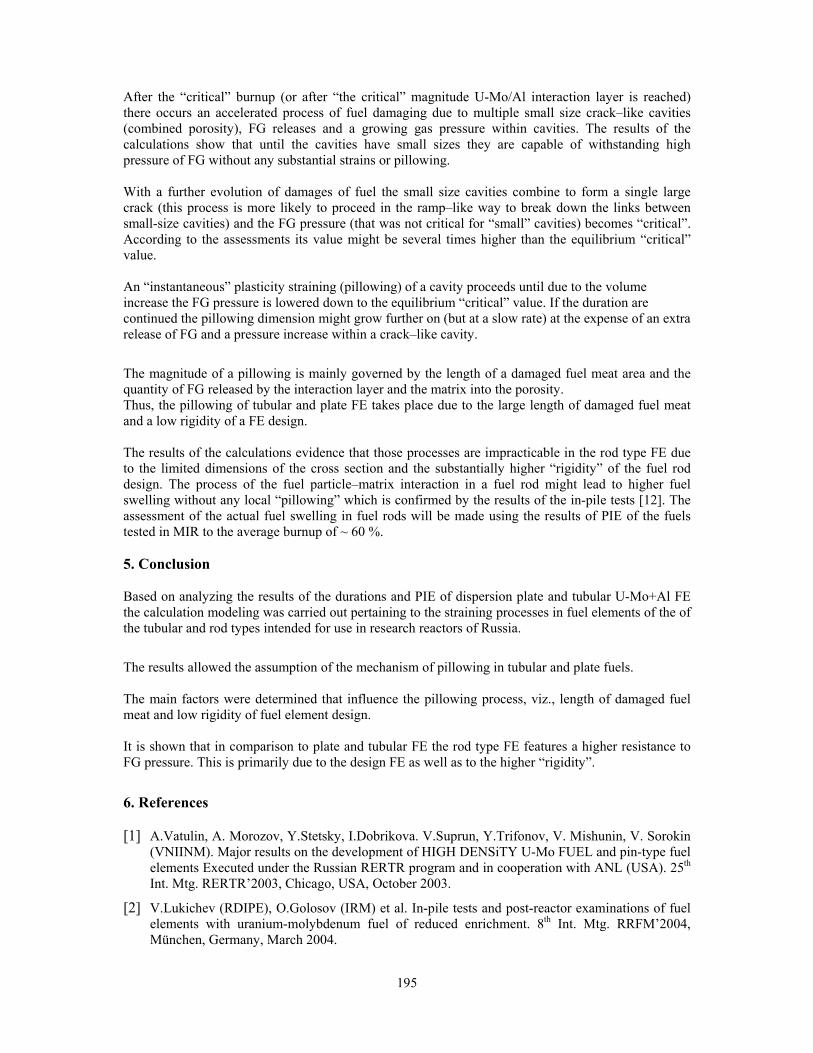
195
After the “critical” burnup (or after “the critical” magnitude U-Mo/Al interaction layer is reached) there occurs an accelerated process of fuel damaging due to multiple small size crack–like cavities (combined porosity), FG releases and a growing gas pressure within cavities. The results of the calculations show that until the cavities have small sizes they are capable of withstanding high pressure of FG without any substantial strains or pillowing. With a further evolution of damages of fuel the small size cavities combine to form a single large crack (this process is more likely to proceed in the ramp–like way to break down the links between small-size cavities) and the FG pressure (that was not critical for “small” cavities) becomes “critical”. According to the assessments its value might be several times higher than the equilibrium “critical” value. An “instantaneous” plasticity straining (pillowing) of a cavity proceeds until due to the volume increase the FG pressure is lowered down to the equilibrium “critical” value. If the duration are continued the pillowing dimension might grow further on (but at a slow rate) at the expense of an extra release of FG and a pressure increase within a crack–like cavity.
The magnitude of a pillowing is mainly governed by the length of a damaged fuel meat area and the quantity of FG released by the interaction layer and the matrix into the porosity. Thus, the pillowing of tubular and plate FE takes place due to the large length of damaged fuel meat and a low rigidity of a FE design. The results of the calculations evidence that those processes are impracticable in the rod type FE due to the limited dimensions of the cross section and the substantially higher “rigidity” of the fuel rod design. The process of the fuel particle–matrix interaction in a fuel rod might lead to higher fuel swelling without any local “pillowing” which is confirmed by the results of the in-pile tests [12]. The assessment of the actual fuel swelling in fuel rods will be made using the results of PIE of the fuels tested in MIR to the average burnup of ~ 60 %.
5. Conclusion Based on analyzing the results of the durations and PIE of dispersion plate and tubular U-Mo+Al FE the calculation modeling was carried out pertaining to the straining processes in fuel elements of the of the tubular and rod types intended for use in research reactors of Russia.
The results allowed the assumption of the mechanism of pillowing in tubular and plate fuels. The main factors were determined that influence the pillowing process, viz., length of damaged fuel meat and low rigidity of fuel element design. It is shown that in comparison to plate and tubular FE the rod type FE features a higher resistance to FG pressure. This is primarily due to the design FE as well as to the higher “rigidity”.
6. References [1] A.Vatulin, A. Morozov, Y.Stetsky, I.Dobrikova. V.Suprun, Y.Trifonov, V. Mishunin, V. Sorokin
(VNIINM). Major results on the development of HIGH DENSiTY U-Mo FUEL and pin-type fuel elements Executed under the Russian RERTR program and in cooperation with ANL (USA). 25th Int. Mtg. RERTR’2003, Chicago, USA, October 2003.
[2] V.Lukichev (RDIPE), O.Golosov (IRM) et al. In-pile tests and post-reactor examinations of fuel elements with uranium-molybdenum fuel of reduced enrichment. 8th Int. Mtg. RRFM’2004, München, Germany, March 2004.
196
[3] A.Vatulin, Y.Stetsky, I.Dobrikova (VNIINM). Unified Fuel Elements Development for Research Reactors. 21st Int. Mtg. RERTR’98, Sao-Paulo, Brazil, October 1998.
[4] V.A.Starkov, V.V.Pimenov, N.G.Gataullin, Y.B.Chertkov, V.E.Fedoseev (NIIAR, Dimitrovgrad) and A.V.Vatulin, I.V.Dobrikova. G.V.Kulakov (VNIINM). Substantiation of the conditions of in-pile tests of LEU high density fuel for research reactors. 7th Int. Mtg. RRFM’2003, Aix-en-Provence, France, March 2003.
[5] V.V.Popov and M.Y.Khmelevsky (IPPE), V.G.Aden, E.F.Kartashov and V.A.Lukichov (RDIPE). The results of computational study of stressed-strained state kinetics in a research reactor fuel element with (U-9%Mo)-Al dispersive fuel irradiated in the IVV-2M reactor. 8th Int. Mtg. RRFM’2004, München, Germany, March 2004.
[6] P.Lemoine, J.L.Snelgrove, N.Arkhangelsky, L.Alvarez. UMo dispersion fuel results and status of qualification programs. 8th Int. Mtg. RRFM’2004, München, Germany, March 2004.
[7] JM.Hamy, P.Lemoine, F.Huet et al. Status as of march 2004 of the French UMo group development program. 8th Int. Mtg. RRFM’2004, München, Germany, March 2004.
[8] G.L.Hofman, M.K.Meyer, F.Huet et al. Recent observations at the postirradiation examination of low-enriched U-Mo miniplates irradiated to high burnup. 8th Int. Mtg. RRFM’2004, München, Germany, March 2004.
[9] MARC. Version К7. Volume А-Е.
[10] A.A.Bochvar. Materials Science, 5th ed, M., Metallurgy-1956.
[11] I.F. Kolobnev. Heat Resistance of Cast Al alloy. 2nd ed. M., Metallurgy-1973.
[12] C.K.Kim, K.H.Kim, J.M.Park and D.S.Sohn. Efforts to overcome the failure occurring in rod type U-Mo fuel irradiation test for HANARO in KAERI. 7th Int. Mtg. RRFM’2003, Aix-en-Provence, France, March 2003.
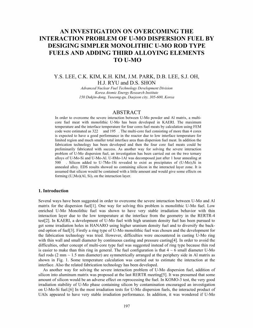
197
AN INVESTIGATION ON OVERCOMING THE INTERACTION PROBLEM OF U-MO DISPERSION FUEL BY
DESIGING SIMPLER MONOLITHIC U-MO ROD TYPE FUELS AND ADDING THIRD ALLOYING ELEMENTS
TO U-MO
Y.S. LEE, C.K. KIM, K.H. KIM, J.M. PARK, D.B. LEE, S.J. OH, H.J. RYU and D.S. SHON
Advanced Nuclear Fuel Technology Development Division Korea Atomic Energy Research Institute
150 Dukjin-dong, Yuseong-gu, Daejeon city, 305-600, Korea
ABSTRACT
In order to overcome the severe interaction between U-Mo powder and Al matrix, a multi-core fuel meat with monolithic U-Mo has been developed in KAERI. The maximum temperature and the interface temperature for four cores fuel meats by calculation using FEM code were estimated as 322 � and 195�. The multi-core fuel consisting of more than 4 cores is expected to have a good performance in the reactor due to low interface temperature for limited region and much smaller total interface area than dispersion fuel meat. In addition the fabrication technology has been developed and then the four core fuel meats could be preliminarily fabricated with success. As another way for solving the severe interaction problem of U-Mo dispersion fuel, an investigation has been carried out on the two ternary alloys of U-Mo-Si and U-Mo-Al. U-8Mo-1Al was decomposed just after 1 hour annealing at 500 �. Silicon added to U-7Mo-1Si revealed to exist as precipitates of (U-Mo)3Si in annealed alloy. EDS results showed no containing silicon in the interacted layer zone. It is assumed that silicon would be contained with a little amount and would give some effects on forming (U,Mo)(Al, Si)3 on the interaction layer.
1. Introduction Several ways have been suggested in order to overcome the severe interaction between U-Mo and Al matrix for the dispersion fuel[1]. One way for solving this problem is monolithic U-Mo fuel. Low enriched U-Mo Monolithic fuel was shown to have very stable irradiation behavior with thin interaction layer due to the low temperature at the interface from the geometry in the RERTR-4 test[2]. In KAERI, a development of U-Mo fuel with high uranium density fuel has been pursued to get some irradiation holes in HANARO using higher uranium density fuel and to diversify the back-end option of fuel[3]. Firstly a ring type of U-Mo monolithic fuel was chosen and the development for the fabrication technology was tried. However, difficulties were encountered in casting U-Mo ring with thin wall and small diameter by continuous casting and pressure casting[4]. In order to avoid the difficulties, other concept of multi-core type fuel was suggested instead of ring type because thin rod is easier to make than thin ring in general. The fuel configuration is that 4 ~ 6 small diameter U-Mo fuel rods (2 mm ~ 1.5 mm diameter) are symmetrically arranged at the periphery side in Al matrix as shown in Fig. 1. Some temperature calculation was carried out to estimate the interaction at the interface. Also the related fabrication technology has been developed.
As another way for solving the severe interaction problem of U-Mo dispersion fuel, addition of silicon into aluminum matrix was proposed at the last RERTR meeting[5]. It was presumed that some amount of silicon would be an adverse effect on reprocessing the fuel. In KOMO-3 test, the very good irradiation stability of U-Mo phase containing silicon by contamination encouraged an investigation on U-Mo-Si fuel.[6] In the most irradiation tests for U-Mo dispersion fuels, the interacted product of UAlx appeared to have very stable irradiation performance. In addition, it was wondered if U-Mo
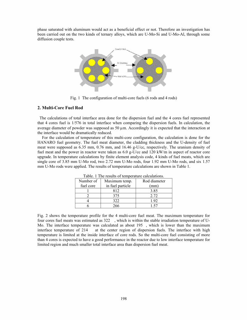
198
phase saturated with aluminum would act as a beneficial effect or not. Therefore an investigation has been carried out on the two kinds of ternary alloys, which are U-Mo-Si and U-Mo-Al, through some diffusion couple tests.
Fig. 1 The configuration of multi-core fuels (6 rods and 4 rods)
2. Multi-Core Fuel Rod The calculations of total interface area done for the dispersion fuel and the 4 cores fuel represented that 4 cores fuel is 1/576 in total interface when comparing the dispersion fuels. In calculation, the average diameter of powder was supposed as 50 μm. Accordingly it is expected that the interaction at the interface would be dramatically reduced.
For the calculation of temperature of this multi-core configuration, the calculation is done for the HANARO fuel geometry. The fuel meat diameter, the cladding thickness and the U-density of fuel meat were supposed as 6.35 mm, 0.76 mm, and 16.46 g-U/cc, respectively. The uranium density of fuel meat and the power in reactor were taken as 6.0 g-U/cc and 120 kW/m in aspect of reactor core upgrade. In temperature calculations by finite element analysis code, 4 kinds of fuel meats, which are single core of 3.85 mm U-Mo rod, two 2.72 mm U-Mo rods, four 1.92 mm U-Mo rods, and six 1.57 mm U-Mo rods were applied. The results of temperature calculations are shown in Table 1.
Table. 1 The results of temperature calculations. Number of fuel core
Maximum temp. in fuel particle
Rod diameter (mm)
1 812 � 3.85 2 375 � 2.72 4 322 � 1.92 6 266 � 1.57
Fig. 2 shows the temperature profile for the 4 multi-core fuel meat. The maximum temperature for four cores fuel meats was estimated as 322 �, which is within the stable irradiation temperature of U-Mo. The interface temperature was calculated as about 195�, which is lower than the maximum interface temperature of 214 � at the center region of dispersion fuels. The interface with high temperature is limited at the inside interface of core rods. So the multi-core fuel consisting of more than 4 cores is expected to have a good performance in the reactor due to low interface temperature for limited region and much smaller total interface area than dispersion fuel meat.

199
Fig. 2 the temperature profile of the 4 multi-core fuel
In order to establish the fabrication process of multi-core fuel, an injection casting technology was applied to make small diameter U-Mo rods. Uranium and molybdenum metal pieces were melted in the crucible under the vacuum atmosphere (4x10⁻² torr). As soon as quartz tubes are lowered and dipped into the melt, Ar gas was fed into the melting chamber until atmosphere pressure. Then the melt was filled up along the quartz tube. In this way U-Mo rods of 2 mm in diameter were successfully produced by this method. (Fig. 3)
Fig. 3 A U-Mo rod 2 mm in diameter produced by injection casting method.
In order to make fuel meat an aluminum rod was prepared and then four 2 mm round grooves were machined on it as shown in Fig. 4. And then the U-Mo rods were inserted into grooves and clad with aluminum by using two kinds of technologies, which are co-extrusion method and swaging method. The clad fuel rod by co-extrusion method appeared some drawback of leaving not filling region at the deep and small space between fuel rod and groove surface as shown in Fig. 5. On the other hand, the swaging method was available for making sound 4 cores fuel meat as shown in Fig. 6.
Fig 4. Al rods with 4 excavated grooves. Fig. 5 A 4 multi-core fuel rod Fig. 6 A 4 multi-core fuel
produced by extrusion. meat produced by swaging.

200
3. Third element addition in U-Mo
U-7Mo, U-8Mo-1Si, and U-8Mo-1Al alloys were prepared by melting to 1400 � by induction heating and casting in Cu molds of 12 mm inside diameter. The as-cast specimens were heat-treated in a vacuum at 900 � for 100 hrs to ensure compositional homogeneity and to form gamma phase, and then quenched to room temperature. Quenched U-Mo-X ternary alloys were annealed in vacuum sealed quartz tubes for 1, 24 hrs to investigate the gamma phase stability. The microstructures were examined by SEM. X-ray diffraction (XRD) analysis was applied to identify the gamma phase stability. The results showed that U-8Mo-1Al was decomposed just after 1 hour but U-7Mo and U-8Mo-1Si maintained gamma phase after 24 hrs from the XRD results as shown in Fig.7. Even though U-7Mo and U-8Mo-1Si maintained gamma phase, U-7Mo shows to have decomposed into lamella structure almost due to micro-decomposition of gamma phase as in Fig. 8. However, U-8Mo-1Si shows the decomposed lamella structure exists around precipitation compound partially as shown in Fig. 9. In general, silicon is assumed to be more effective on gamma phase stability than aluminum.
Fig. 7 The variations of X-ray diffraction patterns with annealing time at 500 �
Fig. 8 The microstructural change of U-7Mo Fig. 9 The microstructural change of U-8Mo-1Si
at 500 � after 24 hrs. at 500 � after 24 hrs.
Fig. 10 (next page) is a micrograph showing the results of the U-7Mo-1Si diffusion couple test. Silicon added to U-7Mo-1Si revealed to exist as precipitates of (U-Mo)3Si in annealed alloy. The matrix phase of annealed alloy was analyzed to be U-7Mo on EDS. However, the phase with low silicon content in U-Mo tube of KOMO-3 was analyzed as containing 0.2 wt.% silicon as shown in Fig. 10. So it is assumed that the matrix phase of annealed U-Mo-Si alloy contains a little of silicon of
20 30 40 50 60 70 80
0
500
1000
1500
2000
2500
U-7Mo500oC 24h
U-8Mo-1Si500oC 24h
U-8Mo-1Al500oC 24h
Inte
nsity
(CP
S)
Two Theta
20 30 40 50 60 70 80
0
500
1000
1500
2000
2500
3000
3500
4000
U-7Mo500oC 1h
U-8Mo-1Si500oC 1h
U-8Mo-1Al500oC 1h
Inte
nsity
(CP
S)
Two Theta

201
about 0.2 wt.%. In the interacted layer zone, even though EDS results showed no containing silicon, it is assumed that silicon would be contained with a little amount and would give some effects on forming (U,Mo)(Al, Si)3 on the interaction layer. Accordingly the further study is required.
Fig. 10. Diffusion couple test result Fig. 11 Irradiation test results of U-7Mo
with U-7Mo-1Si/Al monolithic tube of KOMO3. 4. Summary In order to avoid the interaction problem and to get uranium high-density fuel in connection with reactor upgrade a multi-core fuel meat with monolithic U-Mo has been developed in KAERI. The maximum temperature for four cores fuel meats was estimated as 322 �, which is within the stable irradiation temperature of U-Mo. The interface temperature was calculated as about 195�, which is lower than the maximum interface temperature of 214 � at the center region of dispersion fuels. The interface with high temperature is limited at the inside interface of core rods. So the multi-core fuel consisting of more than 4 cores is expected to have a good performance in the reactor due to low interface temperature for limited region and much smaller total interface area than dispersion fuel meat. In addition the fabrication technology has been developed and then the four core fuel meats could be preliminarily fabricated with success. As another way for solving the severe interaction problem of U-Mo dispersion fuel, an investigation has been carried out on the two kinds of ternary alloys, which are U-Mo-Si and U-Mo-Al, through some diffusion couple tests. U-8Mo-1Al was decomposed just after 1 hour annealing at 500 �. Silicon added to U-7Mo-1Si revealed to exist as precipitates of (U-Mo)3Si in annealed alloy. EDS results showed no containing silicon in the interacted layer zone. However, it is assumed that silicon would be contained with a little amount and would give some effects on forming (U,Mo)(Al, Si)3 on the interaction layer. Accordingly the further study is required. 5. Acknowledgements The authors would like to express their appreciation to the Ministry of Science and Technology (MOST) of Korea for its supports of this work through the National Nuclear R&D Project. 6. References [1] Armando Travelli, Intl. Meeting on Reduced Enrichment for Research and Test Reactors, RERTR
2004
[2] C.R. Clark, Intl. Meeting on Reduced Enrichment for Research and Test Reactors, RERTR 2004
[3] K.H. Lee, et al, Intl. Meeting on Reduced Enrichment for Research and Test Reactors, RERTR 2002.
7Mo U-
Al
(U-Mo)Si precipitates
(U,Mo)Al no Si
U91.31M8.47Si0.21
U74.38Mo14.93Si10.7

202
[4] C.K. Kim, et al, “Development of the Continuous Casting Technology for Fabrication of Depleted Uranium”, Korean Nuclear Society fall conference, 2003
[5] G.L. Hofman, M.R. Finlay, Y.S. Kim, Intl. Meeting on Reduced Enrichment for Research and Test Reactors, RERTR 2004
[6] C.K. Kim et al, Intl. Meeting on Reduced Enrichment for Research and Test Reactors, RERTR 2004

203
INTERDIFFUSION BETWEEN U-Mo ALLOYS AND Al OR Al ALLOYS AT 340 ºC. IRRADIATION PLAN
A.M. FORTIS, M. MIRANDOU, M. ORTIZ and S. BALART Departamento Materiales, CAC, CNEA
Avda. Gral Paz 1499, B1650KNA, San Martin, Argentina
A. DENIS Departamento Combustibles CAC, CNEA
Avda. Gral Paz 1499, B1650KNA, San Martin, Argentina
A. MOGLIONI and P. CABOT Departamento ENDE, CAC, CNEA
Avda. Gral Paz 1499, B1650KNA, San Martin, Argentina
ABSTRACT Out of reactor interdiffusion experiments between U-Mo alloys and Al alloys made close to fuel operation temperature are needed to validate the results obtained above 500 ºC. A study of interdiffusion between U-Mo and Al or Al alloys, out and in reactor, has been initiated. The objective is to characterize the interdiffusion layer around 250 ºC and study the influence of neutron irradiation. Irradiation experiments will be performed in the argentine RA3 reactor and chemical diffusion couples will be fabricated by Friction Stir Welding (FSW) technique. In this work out-of-pile diffusion experiments performed at 340ºC are presented. Friction Stir Welding (FSW) was used to fabricate some of the samples. One of the results is the presence of Si, in the interaction layer, coming from the Al alloy. This is promising in the sense that the absence of Al rich phases may also be expected at low temperature.
1. Introduction The dispersion of U-(7wt% to 10wt%)Mo alloy particles in Al matrix considered to perform well under irradiation in miniplates experiments [1], showed non desirable behaviors in full-size qualifying experiments [2, 3]. They were attributed to a large interaction between U-Mo particles and the Al of the matrix. The extent and properties under irradiation of the reaction (due to interdiffusion) are important in U-Mo /Al dispersion fuel. It has been suggested that the modification of the Al matrix by a convenient alloying of the Al could change the interaction layer and improve its irradiation behavior [4]. Out-of-pile interdiffusion experiments between U-Mo and Al have been performed at temperatures above 300 ºC [5,6,7], for the case of Al alloys the temperatures were above 500 ºC [6]. The reduction in the annealing temperature implies very long term experiments. Nevertheless, these kind of experiments, made close to fuel operation temperature, are needed to validate the results obtai ned at high temèratures. A long term study of interdiffusion between U-Mo and Al or Al alloys, out and in reactor, has been initiated, to characterize the interdiffusion layer at low temperature (around 250 ºC) and to study the influence of neutron irradiation. In this work out-of-pile diffusion experiments performed, in a first stage, at 340ºC are presented. Friction Stir Welding (FSW) was used to fabricate some of the samples to corroborate the use of this technique in diffusion couples at low temperatures. This technique appears to be more suitable to fabricate couples to be irradiated than the ones made with clamps because it enables to encase a foil of U-Mo alloy in Al alloy as in the case of monolithic fuel elements (MFE) [8,9]. In the fabrication of a MFE, two cladding of Al plates are welded face to face with the metallic foil in between them. In this
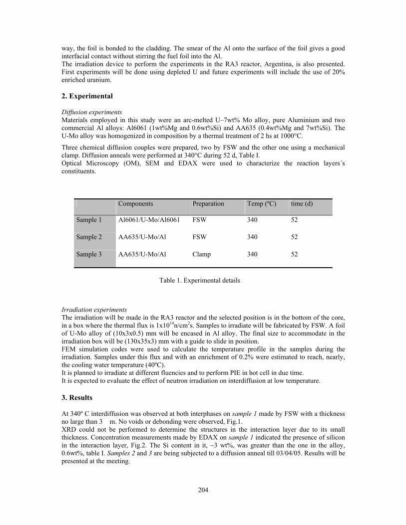
204
way, the foil is bonded to the cladding. The smear of the Al onto the surface of the foil gives a good interfacial contact without stirring the fuel foil into the Al. The irradiation device to perform the experiments in the RA3 reactor, Argentina, is also presented. First experiments will be done using depleted U and future experiments will include the use of 20% enriched uranium. 2. Experimental Diffusion experiments Materials employed in this study were an arc-melted U–7wt% Mo alloy, pure Aluminium and two commercial Al alloys: Al6061 (1wt%Mg and 0.6wt%Si) and AA635 (0.4wt%Mg and 7wt%Si). The U-Mo alloy was homogenized in composition by a thermal treatment of 2 hs at 1000°C.
Three chemical diffusion couples were prepared, two by FSW and the other one using a mechanical clamp. Diffusion anneals were performed at 340°C during 52 d, Table I. Optical Microscopy (OM), SEM and EDAX were used to characterize the reaction layers´s constituents.
Components Preparation Temp (ºC) time (d)
Sample 1 Al6061/U-Mo/Al6061 FSW 340 52
Sample 2 AA635/U-Mo/Al FSW 340 52
Sample 3 AA635/U-Mo/Al Clamp 340 52
Irradiation experiments The irradiation will be made in the RA3 reactor and the selected position is in the bottom of the core, in a box where the thermal flux is 1x10¹⁴n/cm2s. Samples to irradiate will be fabricated by FSW. A foil of U-Mo alloy of (10x3x0.5) mm will be encased in Al alloy. The final size to accommodate in the irradiation box will be (130x35x3) mm with a guide to slide in position. FEM simulation codes were used to calculate the temperature profile in the samples during the irradiation. Samples under this flux and with an enrichment of 0.2% were estimated to reach, nearly, the cooling water temperature (40ºC). It is planned to irradiate at different fluencies and to perform PIE in hot cell in due time. It is expected to evaluate the effect of neutron irradiation on interdiffusion at low temperature. 3. Results At 340º C interdiffusion was observed at both interphases on sample 1 made by FSW with a thickness no large than 3 �m. No voids or debonding were observed, Fig.1. XRD could not be performed to determine the structures in the interaction layer due to its small thickness. Concentration measurements made by EDAX on sample 1 indicated the presence of silicon in the interaction layer, Fig.2. The Si content in it, ~3 wt%, was greater than the one in the alloy, 0.6wt%, table I. Samples 2 and 3 are being subjected to a diffusion anneal till 03/04/05. Results will be presented at the meeting.
Table 1. Experimental details

205
The irradiation plan has been presented to the Regulatory Authority and its approval is being awaited to start the irradiations. 4. Discussion and summary In a previous work [9] FSW was successfully used to prepare diffusion couples which annealed at 550ºC gave satisfactory results. This work indicates that FSW remains valid for low temperature diffusion anneals. In diffusion experiments performed between U-Mo and Al alloys, at 550ºC [10] the presence of Si in the interdiffusion layer, was associated to the existence of the phase (U,Mo)(Al,Si)3 and the absence of (U,Mo)Al4. Although in this work no structure identification of the phases that constitute the interaction layer was made, the presence of Si is promising in the sense that the absence of Al rich phases may be also expected at low temperature. 5. Acknowledgments Authors want to thank the technical staff of the Departamento de Materiales CAC-CNEA for their help in the experimental work, and M. Rosenbusch from Dto. Química de Reactores CAC-CNEA for SEM observations and R. Acuña from Aluar S.A. for the AA635 alloy. This work was partially financed by the Agencia Nacional de Promoción Científica y Tecnológica, proyect PICT Nº 12-11186. 6. References [1] M. K. Meyer, G.L Hofman, S.L. Hayes, C.R. Clark, T. C. Wiencewk, J.L. Snelgrove, R. V. Starin, K.H. Kim, “Low temperatures irradiation behavior of Uranium- Molybdenum Alloy Dispersion fuel”. J. Nucl.Mat.,304, (2002), 221-236.
[2] L.M. Hamy, P. Lemoine, F. Huet, B. Guigon, C. Jarousse, J. Emin, “Status as of March 2004 of the French Umo Group Development Program”. 8th International Topical meeting Research Reactor Fuel management (RRFM), Munich, Germany, March 21-24, 2004.
[3] A. Leenaers, S. Van den Berghe, E. Koonen, C. Jarousse, F. Huet,, M. Trotabas , M. Boyard, S. Guillot, L Sannen , M. Verwerft, “Post-irradiation examination or Uranium-7wt%Molybdenum Atomized dispersion fuel”. J. Nucl. Mater.335 (2004) 39-47.
Fig. 2: Sample 1. EDAX spectrum on the interaction layer shown in Fig.1.
Fig. 1: Sample 1. Interaction layer between U-7w%Mo/Al 6061. 340ºC,
52 d. Backscattered image.
U-Mo
Al 6061

206
[4] G.L. Hofman, M.R. Finley, Y-S. Kim. “Post-irradiation analysis of U-Mo/Al dispersión fuels miniplate test, RERTR 4 & 5”. 2004 International Meeting on Reduced Enrichment for Research and Test Reactors, Vienna, Austria, November 7-12, 2004[5] Ho Jin Ryu, Young Soo Han, Jong Man Park, Soon Dal Park, Chang Kyu Kim. “Reaction layer growth and reaction heat of U-Mo/Al dispersion fuels using centrifugally atomized powder”. Journal of Nucl. Mater. 321 (2003) 210-220.
[6] M. I. Mirandou, S. N. Balart, M. Ortiz, M. S. Granovsky. “Reaction layer in U- 7wt%Mo /Al diffusion couples”. J. of Nucl. Mater, 323, (2003), 29-35.
[7] D.Sears, A.Davidson, J.Mason, C.Buchanan and P.Ryan. 2004 International Meeting on Reduced Enrichment for Research and Test Reactors, Vienna, Austria, November 7-12, 2004]
[8] C.R. Clark, T. C. Wiencewk, M.R. Finlay, R. L. Briggs, D. M. Wachs, S.L. Hayes, G.L Hofman, C. J. Mothershead. “Update on fuel fabrication development and testing at Argonne National Laboratory”. 2004 International Meeting on Reduced Enrichment for Research and Test Reactors, Vienna, Austria, November 7-12, 2004.
[9] P. Cabot, A. Monglioni, M. Mirandou, S. Balart. “CNEA experiments to apply Friction Stir Welding to encase U-Mo foils in Al”. 2004 International Meeting on Reduced Enrichment for Research and Test Reactors, Vienna, Austria, November 7-12, 2004.
[10] M. Mirandou, M. Granovsky, M. Ortiz, S. Balart, S. Aricó and L. Gribaudo. “Reaction layer between U-7wt%Mo and Al alloys in chemical diffusion couples”. 2004 International Meeting on Reduced Enrichment for Research and Test Reactors, Vienna, Austria, November 7-12, 2004.

207
IRRADIATION AND POST-IRRADIATION EXAMINATION FACILITIES IN ARGENTINA FOR TESTING OF HIGH
DENSITY U COMPOUND PLATES
G. Ruggirello, S. Halpert, G. Estryk, J. Quintana Comisión Nacional Energía Atómica (CNEA)
Avda del Libertador 8250, (1429) Buenos Aires, Argentina 1. INTRODUCTION In the last years, CNEA has implemented a complete infrastructure for the performing of post irradiation examination (PIE) on MTR fuel elements. This includes fuel element control inside the reactor pool and spent fuel storage pool (SFSP) by an underwater inspection station and destructive evaluation facilities at Hot Cells according with the methodologies developed at Argonne National Laboratory. The new challenge is the implementation of a system for the irradiation of miniplates containing U compounds with high density. The irradiation will be performed in RA-3 reactor in normal operation conditions. A special irradiation box to be located in the center of the core (G4 lattice position) was designed in order to irradiate miniplates with different characteristics. The thermal-hydraulic and neutronic calculations were done for various U compounds, meat geometries and cladding materials using the specific code.
2. FACILITY FOR IRRADIATION TESTING
RA 3 Reactor Pool type Maximum Power: 10 MW Cooled and moderated by light water and graphite reflector 4 forks of control plates (Ag-15In-5Cd) Average thermal neutron flux: 8,0x10¹³ n/s.cm2
G-4 lattice position Maximum thermal neutron flux: 2,5x10¹⁴ n/s.cm2
Miniplate average thermal neutron flux: 9,0x10¹³ n/s.cm2
G4
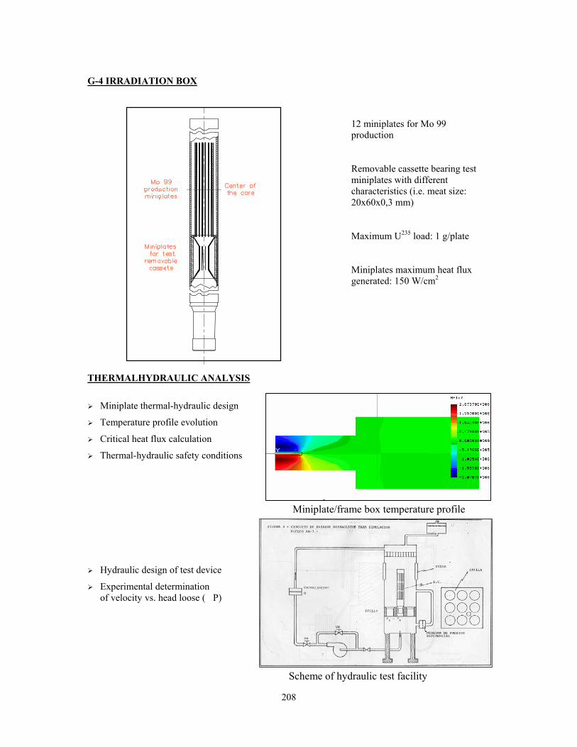
208
G-4 IRRADIATION BOX
12 miniplates for Mo 99 production Removable cassette bearing test miniplates with different characteristics (i.e. meat size: 20x60x0,3 mm) Maximum U235 load: 1 g/plate Miniplates maximum heat flux generated: 150 W/cm2
THERMALHYDRAULIC ANALYSIS
Miniplate thermal-hydraulic design
Temperature profile evolution
Critical heat flux calculation
Thermal-hydraulic safety conditions
Miniplate/frame box temperature profile
Hydraulic design of test device
Experimental determination of velocity vs. head loose (�P)
Scheme of hydraulic test facility

209
TEST MINIPLATES FUEL MANAGEMENT
• Cell constant calculation by means of neutron transport CODE WIMS D4 • Neutron flux measurement by foil activation at G-4 position. • Fuel burn-up calculation by tridimensional neutron diffusion CODE PUMA (option)
detailed modeling at the position of the test miniplates • PUMA – MONTECARLO (MCNP) comparison
VISUAL INSPECTION, NDT AND PLATE SEPARATION IN THE SFSP
The underwater station installed in the spent fuel storage pool allows the separation of the outer plates of a full scale fuel element, together with an exhaustive visual inspection of plates of any size. An underwater eddy current technique can be applied in order to quickly evaluate the oxide growth behavior in situ. The station consists of a shelf at 4.5 m depth, where the fuel element is fixed. The outer fuel plates can be separated by sawing of the structural plate using an underwater pneumatic motor which slides along high precision rails.
210
HOT CELLS LABORATORY
20 cm Lead shielding Two alpha-boxes with four working posts for fuel material destructive and non destructive tests. A beta-gamma cells with five working posts for metallurgical tests (Tensile and impact machine).
A shielded OM with one working post.
Preparation of metallographic samples for OM and SEM The complete PIE analysis includes visual examination, blister test, gamma scanning of the main fission products, metallography and chemical burn-up analysis by U-235 mass spectrometry.

211
COMPUTATIONAL AND EXPERIMENTAL ANALYSIS OF CAUSES FOR LOCAL DEFORMATION OF RESEARCH REACTOR U-Mo FUEL PIN CLADDINGS IN CASE OF
HIGH BURN-UPS
V.V. POPOV, M.Ya. KHMELEVSKY SSC RF-IPPE, Bondarenko Sq. 1, 249033 Obninsk, Russia
V.A. LUKICHEV
FSUE RDIPE, 101000, post-box 788, Moscow, Russia
O.A. GOLOSOV FSUE IRM, 624051, box 29, Zarechniy, Sverdlovsk region, Russia
ABSTRACT Post-reactor investigations of (U-Mo) fuel pins irradiated in the IVV-2M reactor have allowed to determine: the change in a fuel pin volume; the dimensions and the kind of the local deformation of fuel pin claddings; the amount of gases released under the cladding from the fuel composition, the thickness and appearance of the interaction layer of between the (U-Mo) particles and aluminium as a matrix material. The computational analysis of the stressed-strained state of fuel pins has shown that the major contribution to the increase of the fuel pin volume is made by the fuel swelling caused by the solid products of fission being formed in the process of operation. The emergence of the (U-Mo) fuel–aluminium matrix interaction layers around the (U-Mo) particles results in formation and evolution of lamination cavities inside the fuel composition under the joint action of the pressure of process gases and gaseous fission products. In case of high burn-up a local bulge of a fuel pin cladding is being formed in the fuel lamination area caused by the pressure of gases in the presence of creep in the fuel pin cladding material. The computational results relating to the local strain in a research reactor (U-Mo) fuel pin are in a good accordance with the results of the post-reactor investigations.
1. Introduction According to “The Program of Reducing the Enrichment of the Research Reactor Fuels”, in the period from November, 2001 to April, 2002 the life-time testing of two combined fuel assemblies (FAs) of IVV-2M type (KM 003 and KM 004) was being carried out; each of them contained two experimental fuel pins whose fuel, (U-9%Mo)+Al, with uranium enriched by 36% of 235U and had the volumetric density of 5.4 g·cm-3. The average burn-ups by 235U achieved in the course of this in-reactor testing equaled for the KM 003 and KM 004 FAs 22% and 33%, correspondingly. The experimental fuel pins of the KM 003 FA have successfully passed the testing up to the average burn-up of 22% by 235U, which, in terms of the fuel with a 19.7% enrichment by the fission fragment build-up, equals to a 40%burn-up. According to the outcome of the complex material science examinations, the state of the fuel pins and the materials of the components being their members was satisfactory. The experimental fuel pins of the KM 003 FA whose effective durance of testing was of 152 days have achieved an average value of burn-up by 235U equal 33%, which, in terms of the fission fragment build-up, is equivalent to a 60% burn-up for a fuel of a 19.7% enrichment by 235U. In the central region of the both fuel pins of that FA local deformations in the shape of bulges on the inner and outer fuel pin claddings (one for each fuel pin) have been revealed. A certain interaction between the aluminium
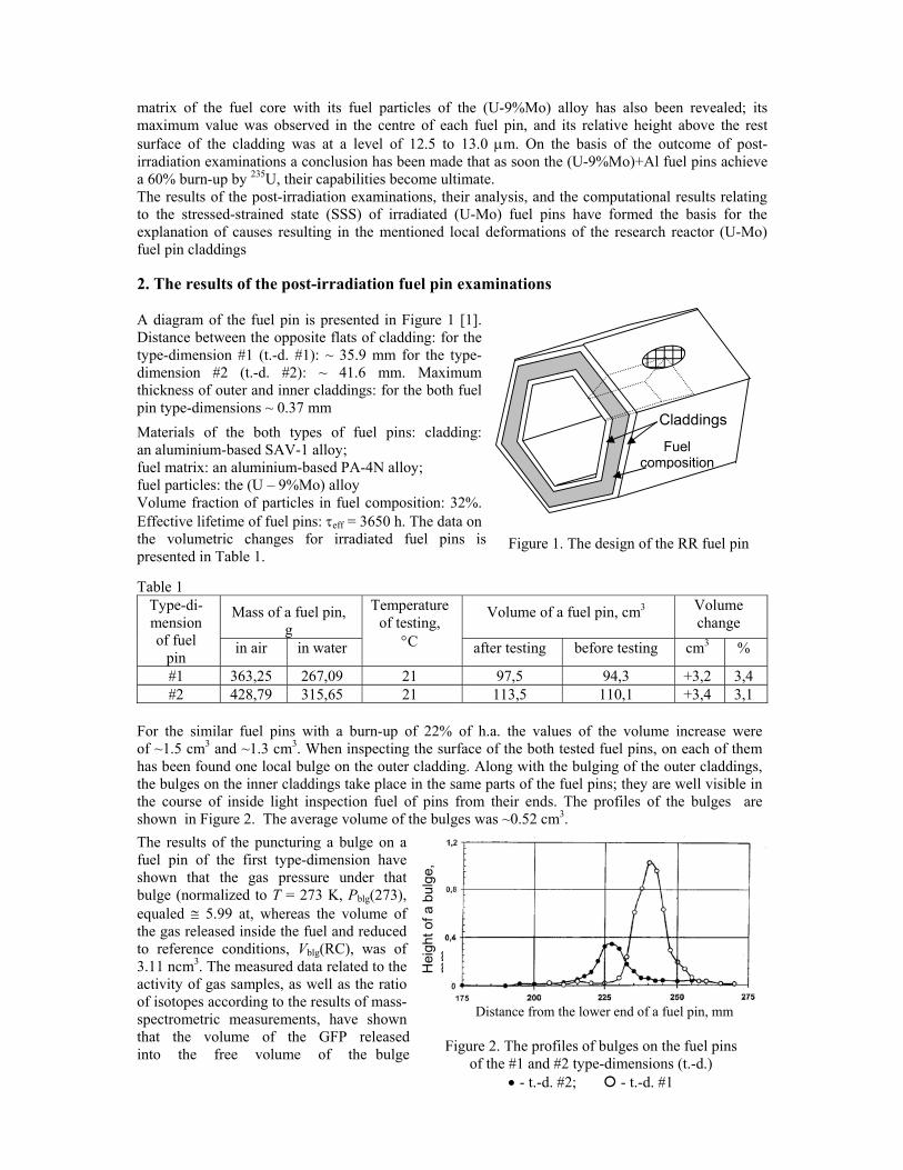
212
matrix of the fuel core with its fuel particles of the (U-9%Mo) alloy has also been revealed; its maximum value was observed in the centre of each fuel pin, and its relative height above the rest surface of the cladding was at a level of 12.5 to 13.0 μm. On the basis of the outcome of post-irradiation examinations a conclusion has been made that as soon the (U-9%Mo)+Al fuel pins achieve a 60% burn-up by 235U, their capabilities become ultimate. The results of the post-irradiation examinations, their analysis, and the computational results relating to the stressed-strained state (SSS) of irradiated (U-Mo) fuel pins have formed the basis for the explanation of causes resulting in the mentioned local deformations of the research reactor (U-Mo) fuel pin claddings 2. The results of the post-irradiation fuel pin examinations A diagram of the fuel pin is presented in Figure 1 [1]. Distance between the opposite flats of cladding: for the type-dimension #1 (t.-d. #1): ~ 35.9 mm for the type-dimension #2 (t.-d. #2): ~ 41.6 mm. Maximum thickness of outer and inner claddings: for the both fuel pin type-dimensions ~ 0.37 mm Materials of the both types of fuel pins: cladding: an aluminium-based SAV-1 alloy; fuel matrix: an aluminium-based PA-4N alloy; fuel particles: the (U – 9%Mo) alloy Volume fraction of particles in fuel composition: 32%. Effective lifetime of fuel pins: τeff = 3650 h. The data on the volumetric changes for irradiated fuel pins is presented in Table 1. Table 1
Mass of a fuel pin, g
Volume of a fuel pin, cm3 Volume change
Type-di-mension of fuel
pin in air in water
Temperatureof testing,
°C after testing before testing cm3 %
#1 363,25 267,09 21 97,5 94,3 +3,2 3,4 #2 428,79 315,65 21 113,5 110,1 +3,4 3,1
For the similar fuel pins with a burn-up of 22% of h.a. the values of the volume increase were of ~1.5 cm3 and ~1.3 cm3. When inspecting the surface of the both tested fuel pins, on each of them has been found one local bulge on the outer cladding. Along with the bulging of the outer claddings, the bulges on the inner claddings take place in the same parts of the fuel pins; they are well visible in the course of inside light inspection fuel of pins from their ends. The profiles of the bulges are shown in Figure 2. The average volume of the bulges was ~0.52 cm3. The results of the puncturing a bulge on a fuel pin of the first type-dimension have shown that the gas pressure under that bulge (normalized to T = 273 K, Pblg(273), equaled ≅ 5.99 at, whereas the volume of the gas released inside the fuel and reduced to reference conditions, Vblg(RC), was of 3.11 ncm3. The measured data related to the activity of gas samples, as well as the ratio of isotopes according to the results of mass-spectrometric measurements, have shown that the volume of the GFP released into the free volume of the bulge
Claddings
Fuel composition
Figure 2. The profiles of bulges on the fuel pins of the #1 and #2 type-dimensions (t.-d.)
• - t.-d. #2; - t.-d. #1
Hei
ght o
f a b
ulge
, m
m
Distance from the lower end of a fuel pin, mm
Figure 1. The design of the RR fuel pin

213
equaled ~2.62 cm3. Thus ~0.5 cm3 is a share of gases of non-radiation origin. The results of the metallographic examinations have shown: • The claddings of the fuel pins in the area of the bulge formation and in the adjacent sections have a strong diffusive bond with their fuel cores. • No peeling of fuel pin claddings from fuel cores has been revealed. The formation of the bulges and their subsequent growth are going forward with the rupture of the fuel core in its central sections. The rupture of the fuel core goes along the line of contact between the interaction zones and the aluminium matrix, see Figure 3. The ruptures in the fuel core, 0.3 to 1.2 mm long, were revealed practically on all other sides of the both fuel pins at a distance of ~215 to 250 mm from the bottom of the fuel pins, that is to say, about 25 to 30 mm lower than the centre of the active layer. Those ruptures of the Figure 3. The appearance of a fuel pin of the fuel core, too, are characterized by #1 type-dimension in its cross section their location over the sections of core that are close to its centre. The qualitative phase composition of the fuel is as follows: phase of aluminium, γ-phase of uranium, phase of uranium aluminides of UAl2 and UAl3 types. 3. The outcome of the computational analysis In order to carry out the computational study of the strained-stressed state (SSS) of a #1 t.-d. fuel pin, including also the region of the fuel composition lamination, the results of the post-irradiation examination of that fuel pin were used as the input data. The change in the volume increase of the fuel composition due to the formation of the solid fission products, to the “frozen” gaseous fission products still remained in the lattice of the fuel composition and to the newly formed products of the (U-Mo)-aluminium matrix interaction, ΔVfuel, was of ≈ 2.68 cm3 (~ 3.2%). For this computation a linear dependence of the fuel swelling rate on time, Sf / t ≈ 8,77·10-4%/h, had been assumed. For the amount of the gaseous fission products (GFP) released from fuel particles into the lamination region, VGFP, the value measured in the post-irradiation examination had been taken: VGFP = 2.61 cm3, and the rate of GFP release into the lamination cavity, VGFP, was assumed to obey the linear law, provided its time dependence amounted to 7.15·10-4 cm3/h. The defect of a “a longitudinal lamination cavity in the fuel composition” type, 25 mm in diameter, that had been assumed for the computation in case of a #1 t.-d. fuel pin, was situated in the centre of the fuel layer on one of the faces of the fuel pin, symmetrically about its axis. The claddings of the fuel pin are loaded both by the pressure of the swelling fuel composition and by the pressure of gases (that is to say, gaseous fission products and process gases) being released into the lamination cavity. The physico-mechanical properties of fuel pin materials and the irradiation parameters are characterized in Ref. [1], and the dimensions of the fuel pins are presented in Section 2. The computational results for the change in the maximum flexure of the #1 t.-d. fuel pin and for the pressure of gases in the in the course of the fuel pin irradiation are shown in Figures 4 and 5. As can be seen in the Figures 4-5, the computational results are rather close to those found in the post-reactor investigations (see Section 2) related to the pressure in the lamination cavity and to the flexure of the cladding. A certain discrepancy between the computation and measurement results can be accounted for the neglect of the process gases action.
Figure 3. The appearance of a fuel pin of the #1 type-dimension in its cross section
9,2
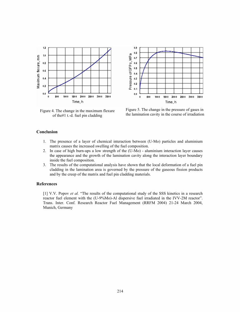
214
Conclusion
1. The presence of a layer of chemical interaction between (U-Mo) particles and aluminium matrix causes the increased swelling of the fuel composition.
2. In case of high burn-ups a low strength of the (U-Mo) - aluminium interaction layer causes the appearance and the growth of the lamination cavity along the interaction layer boundary inside the fuel composition.
3. The results of the computational analysis have shown that the local deformation of a fuel pin cladding in the lamination area is governed by the pressure of the gaseous fission products and by the creep of the matrix and fuel pin cladding materials.
References
[1] V.V. Popov et al. “The results of the computational study of the SSS kinetics in a research reactor fuel element with the (U-9%Mo)-Al dispersive fuel irradiated in the IVV-2M reactor”. Trans. Inter. Conf. Research Reactor Fuel Management (RRFM 2004) 21-24 March 2004, Munich, Germany
Figure 4. The change in the maximum flexure of the#1 t.-d. fuel pin cladding
Figure 5. The change in the pressure of gases in the lamination cavity in the course of irradiation
215
EVALUATION OF 3-D ENERGY DISTRIBUTION IN A PWC/CCD DEVICE COMBINING THERMAL BALANCE METHODS WITH MCNP&ORIGEN-S CALCULATION
MODEL
S. KALCHEVA and Ph. GOUAT SCK•CEN, Belgium Nuclear Research Centre
Boeretang 200, 2400 Mol, Belgium [email protected]; [email protected]
ABSTRACT The on-line determination of the fuel power during fuel irradiation ramp tests, performed in the BR2 reactor, is based on combination of thermal balance methods with 3-D Monte Carlo (MCNP) calculations. The thermal balance methods use thermally insulated rigs, equipped only with temperature and flow rate sensors, allowing measurement of the global energy, deposited in the irradiation device. The detailed 3-D energy distribution in the different parts of the device, including the fuel rod and surrounding structure, is evaluated with MCNP. The developed combined method is able to predict the relative and absolute power distribution in the fuel rod, and the agreement between the forecasts and the measured values is within 4%.
1. Introduction During the last 30 years, SCK•CEN has gained experience in conducting fuel power transient experiments by means of thermal balance methods. Those methods use thermally insulated rigs equipped only with temperature and flow rate sensors. Consequently, the determination of the power in fuel elements contained in such devices requires a model allowing deduction of the power deposited in each subassembly. This kind of model is built by means of reactor physics codes.
Until recently, mainly deterministic 1-D or 2-D codes were used to obtain the necessary theoretical input. Due to the severe geometric approximations in the models, the calculated absolute fuel powers deviated significantly from the measured values. Since 2001 the Monte Carlo code MCNP is used as the most sophisticated tool for modelling of the specific BR2 reactor core configuration and environment of the irradiation devices.
In the frame of the campaign for fuel transient tests, performed at BR2 in 2003, a combined 3-D MCNP-4C&ORIGEN-S calculation model has been implemented for evaluation of the energy, deposited by neutrons and photons in all parts of the irradiation device PWC/CCD, including the fuel rod and surrounding structures. The developed model is able to predict the relative and absolute power distribution as well, and the agreement between the forecasts and the measured values is within 4%. 2. Neutronic modelling of BR2 The full-scale 3-D heterogeneous geometry model of BR2 was developed using the Monte Carlo code MCNP-4C [1,2] and presented at Fig. 1. The model describes the actual twisted hyperboloid reactor core, formed from skew beryllium prisms with individual orientation of the loaded fuel elements, control rods and engineering devices inside the test holes.
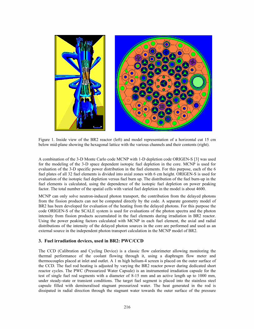
216
Figure 1. Inside view of the BR2 reactor (left) and model representation of a horizontal cut 15 cm below mid-plane showing the hexagonal lattice with the various channels and their contents (right).
A combination of the 3-D Monte Carlo code MCNP with 1-D depletion code ORIGEN-S [3] was used for the modeling of the 3-D space dependent isotopic fuel depletion in the core. MCNP is used for evaluation of the 3-D specific power distribution in the fuel elements. For this purpose, each of the 6 fuel plates of all 32 fuel elements is divided into axial zones with 6 cm height. ORIGEN-S is used for evaluation of the isotopic fuel depletion versus fuel burn up. The distribution of the fuel burn-up in the fuel elements is calculated, using the dependence of the isotopic fuel depletion on power peaking factor. The total number of the spatial cells with varied fuel depletion in the model is about 4600.
MCNP can only solve neutron-induced photon transport, the contribution from the delayed photons from the fission products can not be computed directly by the code. A separate geometry model of BR2 has been developed for evaluation of the heating from the delayed photons. For this purpose the code ORIGEN-S of the SCALE system is used for evaluations of the photon spectra and the photon intensity from fission products accumulated in the fuel elements during irradiation in BR2 reactor. Using the power peaking factors calculated with MCNP in each fuel element, the axial and radial distributions of the intensity of the delayed photon sources in the core are performed and used as an external source in the independent photon transport calculation in the MCNP model of BR2. 3. Fuel irradiation devices, used in BR2: PWC/CCD The CCD (Calibration and Cycling Device) is a classic flow calorimeter allowing monitoring the thermal performance of the coolant flowing through it, using a diaphragm flow meter and thermocouples placed at inlet and outlet. A 1 m high helium-4 screen is placed on the outer surface of the CCD. The fuel rod heating is adjusted by varying the BR2 reactor power during dedicated short reactor cycles. The PWC (Pressurized Water Capsule) is an instrumented irradiation capsule for the test of single fuel rod segments with a diameter of 8-15 mm and an active length up to 1000 mm, under steady-state or transient conditions. The target fuel segment is placed into the stainless steel capsule filled with demineralised stagnant pressurized water. The heat generated in the rod is dissipated in radial direction through the stagnant water towards the outer surface of the pressure

217
capsule by natural convection. The PWC capsule is cooled by the reactor water flow. The calculation model of PWC/CCD is given at Fig. 2.
Figure 2. Calculation model of PWC/CCD − exactly the same model is used in MCNP calculations and in on-line power determination (based on thermal balance method).
4. On-line power determination based on thermal balance method From the equation of energy conservation (in differential form), we have:
⎟⎟⎠
⎞⎜⎜⎝
⎛∂−−= F
dPdhGdQ
ρ (1)
For the coolant flow in the irradiation device. Integration over the height (between the inlet and outlet thermocouples) leads to the equation of the net heat flow rate through the coolant:
[ ]
( ) )2(
),(2
),(),(),(.
__
223
TOTALLOSSSTRUCTUREFUELTOTALLOSSTOTAL
rkFrictionWo
i AVGAVGi
i
orkExpansionW
i AVGAVG
INLETiOUTLET
riationEnthalpyVa
INLETINLETOUTLETOUTLETMEASURED
QQQQQ
PTAG
PTPP
GPThPThGQiiii
i
−+=−=
=−−
−−= ∑∑44444 344444 21444 3444 21
4444444 34444444 21 ρς
ρ
Where: Q is the power (W); G is the mass flow rate (kg/s); h is the specific enthalpy (J/kg); P is the pressure (Pa); �is the specific mass (kg/m³); F is the specific friction work (J/kg); T is the temperature (°C); A is the cross section (m²); �is the dynamic friction loss coefficient.
AISI 304 AISI 321 Aluminium Fission gas Flowing water Fuel Helium Stagnant water Zircaloy 2Beryllium matrix
AISI 304 AISI 316 AISI 321 Aluminium Fission ga Flowing w Fuel HeliumInconel 60Stagnant w Zircaloy 2ZirconiumBeryllium

218
The power (QTOTAL) includes the heat generated not only in the fuel (QFUEL), but also in the structural parts of the device (QSTRUCTURE). Both contributions must be disentangled in order to get information on the total fuel power. The method consists in computing the relative power distribution in all parts of the device (with the fuel rod loaded) by the MCNP reactor physics code with best estimate modelling to take into account all particles transport and the delayed phenomena. Formally we have:
TOTALSTRUCTURESTRUCTURE QWQ ×= , TOTALRODROD QWQ ×= , (3)
in which WSTRUCTURE and WROD are the calculated relative power fractions in all structure parts and in the fuel rod, respectively. The MCNP calculations are performed for a number of BR2 control rod height values and W-values corresponding to the actual control rod height are obtained via interpolation. To obtain the average linear power of the fuel rod , QROD is divided by the length l of the fuel rod.
For most experimental fuel irradiation programs, not the total power in the fuel rod (QROD) itself, but rather the maximum linear power (qROD_MAX) is the crucial parameter. To access this parameter, information on the (instantaneous) axial power profile along the fuel rods is needed:
Bl
Qq ROD
MAXROD =_ , AVGROD
MAXROD
B_
_= (4)
The determination of the maximum linear power in the fuel rod is based on the relative power data obtained from the MCNP calculations. The MCNP calculations yield data for the deposited power in the fuel, subdivided in axial segments of typically 1 to 2 cm length. The resulting axial profiles for the fuel heating can be fitted to determine the B-factors (axial peaking factors) for every control rod position. The resulting values for B as a function of the control rod position are subsequently fitted with polynomial functions, which are implemented in the on-line power determination program to determine instantaneous B-values and thus deduce qROD_MAX data from the QROD values.
5. MCNP evaluations of 3-D energy distribution from various contributors MCNP whole core model (Fig. 1) with incorporated detailed model of PWC/CCD (Fig. 2) was used for evaluation of the 3-D space dependent distribution of the heating, deposited by neutrons and photons into the different structure parts and in the fuel rod. The PWC/CCD device was located into channel E30 of BR2, which was surrounded by 3 fuel channels, 2 reflector channels and 1 channel, containing Control Rod. Detailed axial and radial distributions of the prompt/delayed neutron, prompt/delayed photon heating in the different structure parts (Fig. 3a) and of the linear fission power in the fuel rod (Fig. 3b) have been calculated with MCNP for different positions of the Control Rods.
MCNP calculates the heating caused by neutrons or by γ-rays via the formula:
( ) ( )∫∫=VE
iig
ai V
dVdEErEHQ ,Φ
ρρ
, (5)
where (i = n, γ) is the particle type (neutron or photon), ρa the atom density (atoms per cm3), ρg the mass density (g/cm3), Φi (cm-2.s-1.J-1) the flux per unit energy and Hi(E) the heating response function taking into account all energy deposition processes during neutron and photon transport.
The total fuel rod power is defined as the thermal (fission) power depfisP deposited in the rod by fission
products, betas, gammas and neutrons from the rod itself and by gammas and neutrons, originating from the rest of the reactor:
∑ ∫∫∑∗
==i V
nifE
idep
ifisBRfis
fBR
iifis
depifisn
depfis rEEdrdEE
EP
RENP ),()(,,2,
2,, ϕσρ
ν (6)

219
where: [ ]nfissR ifis /,, is the number of fission reactions, generated by the fissionable isotope i in the
fuel meat; [ ]snN n /, is the intensity of neutrons generated per second in the whole BR2 at the total reactor power 2BRP ; iρ and if ,σ are atomic density and microscopic fission cross section of the
fissionable isotope i; ϕn is the neutron flux [cm-2] per source neutron; fν =2.43 is the average number
of fast neutrons emitted per one fission event, ≈2,BRfisE (193±2)MeV is the effective energy released
per fission reaction of 235U nucleus in BR2 (the standard fuel used in BR2 contains 93% 235U); depifisE ,
is the effective energy deposited in the fuel meat by the fissile nuclei 'i' and normalized per fission event in this fuel.
a) b)
Figure 3: Examples of: a) calculated neutron and photon heating in a part of the structure around the dummy rod, made of steel AISI304; b) evaluated linear power profile for a 40 cm long fuel rod in PWC/CCD with the reactor control rods at a height of 480 mm, scaled to a reactor power of 56 MW.
An important parameter in the calculation for the fuel irradiations is the amount of energy deposited into the test fuel per fission event in this fuel, dep
ifisE , . This parameter is determined using the known decomposition of the fission energy (for the relevant fissile nuclei, 'i' ) into its constituents: the kinetic energy of the fission products and of the emitted neutrons, betas and antineutrinos, and the energy of the prompt and delayed gammas emitted. It is assumed that the antineutrino energy is completely lost. The track length of fission fragments and β-particles is small and they deposit all their energy locally in the fuel meat of the fuel rod. The fission neutrons have higher free path length and they lose their energy during slowing down in elastic and inelastic collisions outside the fuel meat. The prompt and delayed photons may escape from the fuel rod and interact with the surrounding structural elements. On the other hand, gammas originating from outside the test fuel also deposit some power in the fuel rod, which is calculated separately (using the same calculation as for the gamma heating in the structure parts) and is included in order to obtain an effective value for the deposited energy per fission.
Dedicated MCNP calculations were performed to determine the fraction of the gamma energy deposited inside the fuel rod. The source of prompt photons is calculated in the MCNP automatically for fission and neutron capture reactions. The energy of the deposited delayed photons is calculated using MCNP and ORIGEN-S codes as commented in § 2. The heating in the experimental device includes contributions from particles originating from all geometrical parts of the calculation model (from the irradiation channel itself, from all other channels in the reactor core, from the beryllium
-30 -20 -10 0 10 20600
800
1000
1200
1400 MCNP-4C Gaussian Fit
axis of fuel rod (cm)
linea
r fis
sion
pow
er Q
L (W
/cm
)
-80 -60 -40 -20 0 20 40 60 80
0
1
2
3
4
5
6MCNP-4C&ORIGEN-S
neutrons
delayed gamma
prompt+captured gammatotal heating
heat
ing
q, W
per
gra
m
axis of dummy rod (cm)
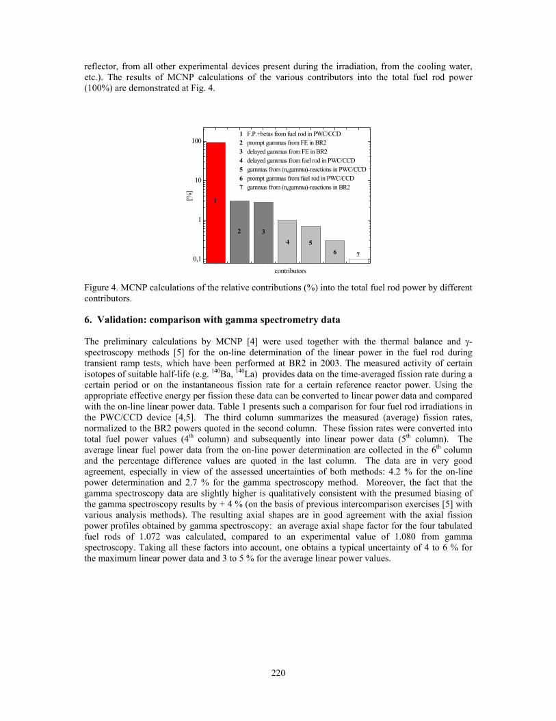
220
reflector, from all other experimental devices present during the irradiation, from the cooling water, etc.). The results of MCNP calculations of the various contributors into the total fuel rod power (100%) are demonstrated at Fig. 4.
Figure 4. MCNP calculations of the relative contributions (%) into the total fuel rod power by different contributors. 6. Validation: comparison with gamma spectrometry data The preliminary calculations by MCNP [4] were used together with the thermal balance and γ-spectroscopy methods [5] for the on-line determination of the linear power in the fuel rod during transient ramp tests, which have been performed at BR2 in 2003. The measured activity of certain isotopes of suitable half-life (e.g. 140Ba, 140La) provides data on the time-averaged fission rate during a certain period or on the instantaneous fission rate for a certain reference reactor power. Using the appropriate effective energy per fission these data can be converted to linear power data and compared with the on-line linear power data. Table 1 presents such a comparison for four fuel rod irradiations in the PWC/CCD device [4,5]. The third column summarizes the measured (average) fission rates, normalized to the BR2 powers quoted in the second column. These fission rates were converted into total fuel power values (4th column) and subsequently into linear power data (5th column). The average linear fuel power data from the on-line power determination are collected in the 6th column and the percentage difference values are quoted in the last column. The data are in very good agreement, especially in view of the assessed uncertainties of both methods: 4.2 % for the on-line power determination and 2.7 % for the gamma spectroscopy method. Moreover, the fact that the gamma spectroscopy data are slightly higher is qualitatively consistent with the presumed biasing of the gamma spectroscopy results by + 4 % (on the basis of previous intercomparison exercises [5] with various analysis methods). The resulting axial shapes are in good agreement with the axial fission power profiles obtained by gamma spectroscopy: an average axial shape factor for the four tabulated fuel rods of 1.072 was calculated, compared to an experimental value of 1.080 from gamma spectroscopy. Taking all these factors into account, one obtains a typical uncertainty of 4 to 6 % for the maximum linear power data and 3 to 5 % for the average linear power values.
0,1
1
10
100
7654
32
1
1 F.P.+betas from fuel rod in PWC/CCD2 prompt gammas from FE in BR23 delayed gammas from FE in BR24 delayed gammas from fuel rod in PWC/CCD5 gammas from (n,gamma)-reactions in PWC/CCD6 prompt gammas from fuel rod in PWC/CCD7 gammas from (n,gamma)-reactions in BR2
[%]
contributors
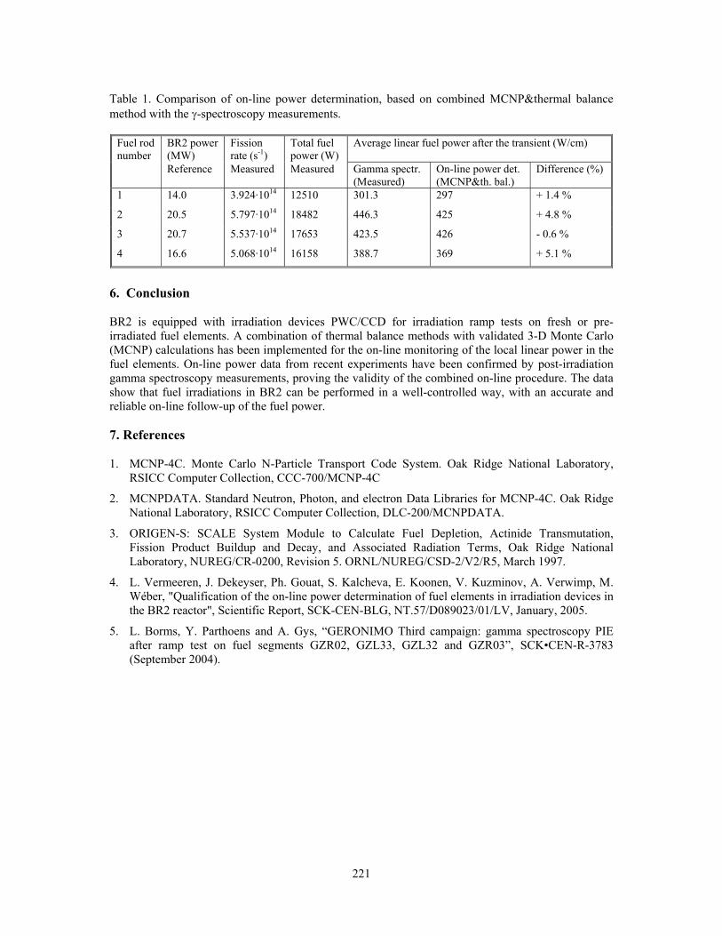
221
Table 1. Comparison of on-line power determination, based on combined MCNP&thermal balance method with the γ-spectroscopy measurements.
Fuel rod number
BR2 power (MW)
Fission rate (s-1)
Total fuel power (W)
Average linear fuel power after the transient (W/cm)
Reference Measured Measured
Gamma spectr. (Measured)
On-line power det. (MCNP&th. bal.)
Difference (%)
1 14.0 3.924·1014 12510 301.3 297 + 1.4 %
2 20.5 5.797·1014 18482 446.3 425 + 4.8 %
3
4
20.7
16.6
5.537·1014
5.068·1014
17653
16158
423.5
388.7
426
369
- 0.6 %
+ 5.1 %
6. Conclusion BR2 is equipped with irradiation devices PWC/CCD for irradiation ramp tests on fresh or pre-irradiated fuel elements. A combination of thermal balance methods with validated 3-D Monte Carlo (MCNP) calculations has been implemented for the on-line monitoring of the local linear power in the fuel elements. On-line power data from recent experiments have been confirmed by post-irradiation gamma spectroscopy measurements, proving the validity of the combined on-line procedure. The data show that fuel irradiations in BR2 can be performed in a well-controlled way, with an accurate and reliable on-line follow-up of the fuel power. 7. References 1. MCNP-4C. Monte Carlo N-Particle Transport Code System. Oak Ridge National Laboratory,
RSICC Computer Collection, CCC-700/MCNP-4C
2. MCNPDATA. Standard Neutron, Photon, and electron Data Libraries for MCNP-4C. Oak Ridge National Laboratory, RSICC Computer Collection, DLC-200/MCNPDATA.
3. ORIGEN-S: SCALE System Module to Calculate Fuel Depletion, Actinide Transmutation, Fission Product Buildup and Decay, and Associated Radiation Terms, Oak Ridge National Laboratory, NUREG/CR-0200, Revision 5. ORNL/NUREG/CSD-2/V2/R5, March 1997.
4. L. Vermeeren, J. Dekeyser, Ph. Gouat, S. Kalcheva, E. Koonen, V. Kuzminov, A. Verwimp, M. Wéber, "Qualification of the on-line power determination of fuel elements in irradiation devices in the BR2 reactor", Scientific Report, SCK-CEN-BLG, NT.57/D089023/01/LV, January, 2005.
5. L. Borms, Y. Parthoens and A. Gys, “GERONIMO Third campaign: gamma spectroscopy PIE after ramp test on fuel segments GZR02, GZL33, GZL32 and GZR03”, SCK•CEN-R-3783 (September 2004).

222
THE VALMONT PROGRAM: ACCURATE EXPERIMENTAL TECHNIQUES TO SUPPORT THE NEUTRONICS
QUALIFICATION OF UMO/AL
J.P. HUDELOT, C. DÖDERLEIN, M. ANTONY, J.M. GIRARD, V. LAVAL, P. FOUGERAS, G. WILLERMOZ, P. LECONTE
CEA Cadarache, DEN/DER 13108 Saint Paul lez Durance, France
ABSTRACT The VALMONT program aimed at qualifying the HORUS3D (HOrowitz Reactor simulation Unified System) neutronics calculation route that is used for the development of the JHR core, and to verify the correct treatment of UMo/Al (20% enrichment in 235U) fuel. The program is composed of two parts. The first part was devoted to the measurement by the oscillation technique of the reactivity effect of UAl/Mo fuel with an accuracy around 1% (1�). The second part consisted of gamma-spectroscopy experiments on a dedicated UMo/Al fuel sample in order to characterize, through axial power profiles and modified conversion ratio of 238U measurements, the production and absorption effects inside the UAl/Mo fuel. The overall excellent agreement between high accuracy experiments and calculations allowed to qualify the HORUS3D neutronics calculation route for UMo/Al fuel.
1. Introduction In the framework of preliminary design on JHR (Jules Horowitz Reactor) Error! Reference source not found.] which will use the UMo/Al LEU high-density fuel, the experimental VALMONT (Validation of ALuminium MOlybdenum uranium fuel for NeuTronics) program in the MINERVE reactor of CEA Cadarache was launched in 2004. The VALMONT program aimed at qualifying the HORUS3D (HOrowitz Reactor simulation Unified System) neutronics calculation route Error! Reference source not found.] that is used for the development of the JHR core, and thus to adapt to UMo/Al fuel specificities, i.e. an enrichment in 235U close to 20% and the presence of the Molyb-denum absorber whose resonances may have interactions with the resonances of the Uranium isotopes. The program is composed of two parts. The first part was devoted to the measurement of reactivity effect of UAl/Mo fuel. The oscillation technique was used and allowed an accuracy on measurements around 1% (1�). Differential effects of the fuel density, the 235U enrichment, the Molybdenum content and the matrix were studied. The second part consisted of gamma-spectroscopy experiments on a dedicated UMo/Al fuel pin in order to characterize the production and absorption effects inside the fuel. Axial power profiles and modified conversion ratio of 238U were particularly investigated. This paper resumes the utilized experimental techniques and the results that were obtained. It also gives a comparison of calculations to experiments. 2. Experiments MINERVE is a pool type reactor operating at a maximum power of 100 watts. The core is submerged under 3 meters of water and is used as a driver zone for the different experiments located in a central square cavity with a size of about 70 cm by 70 cm.

223
The core is contained in a rectangular tank containing about 100 m3 of water. The driver zone consists of enriched metallic uranium/aluminium plates clad with aluminium. These are standard Materials Testing Reactor (MTR) fuel elements. Figure 1 shows the core loading for a typical configuration (R1-UO2). Several lattices corresponding to different neutron spectra can be built in the central region of the MINERVE Reactor. For the VALMONT program, measurements were performed in the PWR/UOx spectrum (R1-UO2 lattice) that is detailed in Figure 2 and corresponds to a moderation ratio Vm/Vf=1.4.
Fig 1. Radial view of the MINERVE Reactor
Experimental Zone
SOUTH NORTH
EAST
WEST HN2
BN1
HN1
BN2
B 4
B 1
B 3
B 2
Source
Pilot Chamber
Thermal Socket
Source 2
Pilot rod Control Rod
Aluminium
Graphite Element
Driver Fuel Element - 18 plates - 93%
Driver Fuel Element - 18 plates - 90%
Driver Fuel Element - 12 plates - 90%
Driver Fuel Element - 9 plates - 90%
Fig 2. PWR/UOx experimental lattice (R1-UO2)
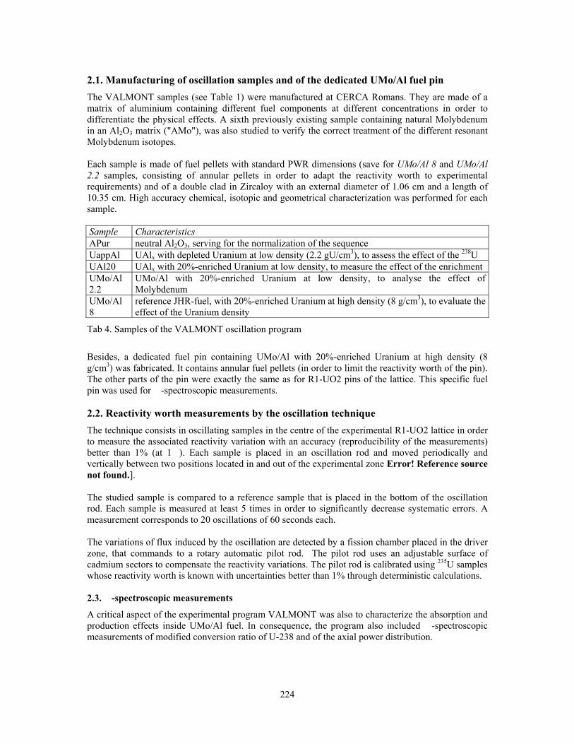
224
2.1. Manufacturing of oscillation samples and of the dedicated UMo/Al fuel pin The VALMONT samples (see Table 1) were manufactured at CERCA Romans. They are made of a matrix of aluminium containing different fuel components at different concentrations in order to differentiate the physical effects. A sixth previously existing sample containing natural Molybdenum in an Al2O3 matrix ("AMo"), was also studied to verify the correct treatment of the different resonant Molybdenum isotopes. Each sample is made of fuel pellets with standard PWR dimensions (save for UMo/Al 8 and UMo/Al 2.2 samples, consisting of annular pellets in order to adapt the reactivity worth to experimental requirements) and of a double clad in Zircaloy with an external diameter of 1.06 cm and a length of 10.35 cm. High accuracy chemical, isotopic and geometrical characterization was performed for each sample. Sample Characteristics APur neutral Al2O3, serving for the normalization of the sequence UappAl UAlx with depleted Uranium at low density (2.2 gU/cm3), to assess the effect of the 238U UAl20 UAlx with 20%-enriched Uranium at low density, to measure the effect of the enrichment UMo/Al 2.2
UMo/Al with 20%-enriched Uranium at low density, to analyse the effect of Molybdenum
UMo/Al 8
reference JHR-fuel, with 20%-enriched Uranium at high density (8 g/cm3), to evaluate the effect of the Uranium density
Tab 4. Samples of the VALMONT oscillation program
Besides, a dedicated fuel pin containing UMo/Al with 20%-enriched Uranium at high density (8 g/cm3) was fabricated. It contains annular fuel pellets (in order to limit the reactivity worth of the pin). The other parts of the pin were exactly the same as for R1-UO2 pins of the lattice. This specific fuel pin was used for �-spectroscopic measurements. 2.2. Reactivity worth measurements by the oscillation technique The technique consists in oscillating samples in the centre of the experimental R1-UO2 lattice in order to measure the associated reactivity variation with an accuracy (reproducibility of the measurements) better than 1% (at 1�). Each sample is placed in an oscillation rod and moved periodically and vertically between two positions located in and out of the experimental zone Error! Reference source not found.].
The studied sample is compared to a reference sample that is placed in the bottom of the oscillation rod. Each sample is measured at least 5 times in order to significantly decrease systematic errors. A measurement corresponds to 20 oscillations of 60 seconds each. The variations of flux induced by the oscillation are detected by a fission chamber placed in the driver zone, that commands to a rotary automatic pilot rod. The pilot rod uses an adjustable surface of cadmium sectors to compensate the reactivity variations. The pilot rod is calibrated using 235U samples whose reactivity worth is known with uncertainties better than 1% through deterministic calculations. 2.3. �-spectroscopic measurements
A critical aspect of the experimental program VALMONT was also to characterize the absorption and production effects inside UMo/Al fuel. In consequence, the program also included �-spectroscopic measurements of modified conversion ratio of U-238 and of the axial power distribution.

225
2.3.1. Axial power distribution The axial profile of the total fission rate was obtained by integral gamma spectroscopy on irradiated fuel pins Error! Reference source not found.]. The gamma-spectroscopy device was made of a standard HPGe detector and adapted electronics, with a lead collimation window allowing the measurement of the fuel pins with axial resolution of 2 cm. 2.3.2. Modified conversion ratio of U-238
The modified conversion ratio is defined as the ratio of the 238U capture rate to the total fission rate inside the pin. It was obtained via gamma spectroscopy measurements of irradiated fuel pins. The determination is based on the measurement of the integral photopeak of a high-yield fission product (FP) relative to the total fission rate inside the fuel pin Error! Reference source not found.]. The specific fission product gamma ray line that is used is the 293.27 keV line from 143Ce. The 277.60 keV gamma ray line from 239Np is used to measure the 238U capture rate because it is related to the number of 238U captures through subsequent beta decays:
PuNpUnU days 239355.2239min5.23239238 ⎯⎯⎯⎯ →⎯⎯⎯⎯ →⎯⎯→⎯+−− ββ
To perform these measurements, a special device has been developed to detect the low energy �-rays with high accuracy using a Low-Energy Germanium detector and adapted electronics. 3. Experimental results – Comparison to calculation results Figure 3 plots the measured reactivity effect (ordinate in arbitrary unit called “pilot unit”) versus the calculated reactivity effect (abscissa) of 235U calibration samples. The slope of the regression line allows to convert the pilot units to calculation units (c.u.). Figure 4 shows the results of the measurements of the VALMONT samples by plotting the measured reactivity effects (converted to c.u.) versus the calculated values. The y-error bars correspond to the measurement uncertainties (2σ). The calculation uncertainties (x-error bars) are due to uncertainties in the material balance of the samples. The plot is normalized to the signal of the inert Al2O3 ("APur") sample. The overall excellent agreement between measurement and calculation is illustrated by the proximity of all points to the diagonal. It is confirmed by the comparison of calculations to experiments given in Table 2. A detailed analysis leads to the following comments Error! Reference source not found.]:
– The absorbing effect of the "AMo" natural Molybdenum sample is calculated with an acceptable deviation of 3.7% (experimental uncertainty: 1.9% at 2σ). Note that a "natural" Molybdenum isotope cross section, that enabled to take into account with high precision the self-shielding interactions of the different natural isotopes, was used for calculations.
– One remarks a change of sign passing from the depleted UO2 sample (UappAl) to the 20%-enriched UAlx sample (U20%Al) and from the low- to the high-density UMo/Al samples (UMo/Al2.2 and UMo/Al8); these deviations, however small, are thought to be linked to approximations in the self-shielding calculation scheme.
– The deviations of the UAlx and UMo/Al fuel samples with the same Uranium loading of 2.2 g/cm3 are identical within the experimental uncertainties. This proves that the Molybdenum effect is correctly treated in the neutronics calculations.
– The deviation experiment-calculation of the RJH reference fuel sample ("UMo/Al 8") amounts to 2.4 c.u. and is thereby within the experimental uncertainty of 2.8 c.u. (2σ). From a qualitative point of view, this result marks the qualification of the neutronics route for this fuel.
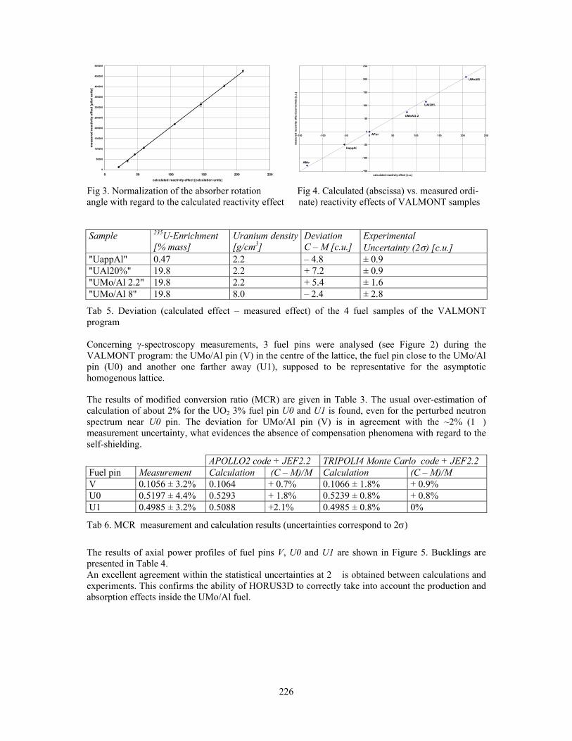
226
0
50000
100000
150000
200000
250000
300000
350000
400000
450000
500000
0 50 100 150 200 250calculated reactivity effect [calculation units]
mea
sure
d re
activ
ity e
ffect
[pilo
t uni
ts]
Fig 3. Normalization of the absorber rotation Fig 4. Calculated (abscissa) vs. measured ordi- angle with regard to the calculated reactivity effect nate) reactivity effects of VALMONT samples Sample 235U-Enrichment
[% mass] Uranium density [g/cm3]
Deviation C – M [c.u.]
Experimental Uncertainty (2σ) [c.u.]
"UappAl" 0.47 2.2 – 4.8 ± 0.9 "UAl20%" 19.8 2.2 + 7.2 ± 0.9 "UMo/Al 2.2" 19.8 2.2 + 5.4 ± 1.6 "UMo/Al 8" 19.8 8.0 – 2.4 ± 2.8
Tab 5. Deviation (calculated effect – measured effect) of the 4 fuel samples of the VALMONT program
Concerning γ-spectroscopy measurements, 3 fuel pins were analysed (see Figure 2) during the VALMONT program: the UMo/Al pin (V) in the centre of the lattice, the fuel pin close to the UMo/Al pin (U0) and another one farther away (U1), supposed to be representative for the asymptotic homogenous lattice.
The results of modified conversion ratio (MCR) are given in Table 3. The usual over-estimation of calculation of about 2% for the UO2 3% fuel pin U0 and U1 is found, even for the perturbed neutron spectrum near U0 pin. The deviation for UMo/Al pin (V) is in agreement with the ~2% (1�) measurement uncertainty, what evidences the absence of compensation phenomena with regard to the self-shielding.
APOLLO2 code + JEF2.2 TRIPOLI4 Monte Carlo code + JEF2.2 Fuel pin Measurement Calculation (C – M)/M Calculation (C – M)/M V 0.1056 ± 3.2% 0.1064 + 0.7% 0.1066 ± 1.8% + 0.9% U0 0.5197 ± 4.4% 0.5293 + 1.8% 0.5239 ± 0.8% + 0.8% U1 0.4985 ± 3.2% 0.5088 +2.1% 0.4985 ± 0.8% 0%
Tab 6. MCR measurement and calculation results (uncertainties correspond to 2σ)
The results of axial power profiles of fuel pins V, U0 and U1 are shown in Figure 5. Bucklings are presented in Table 4. An excellent agreement within the statistical uncertainties at 2� is obtained between calculations and experiments. This confirms the ability of HORUS3D to correctly take into account the production and absorption effects inside the UMo/Al fuel.
-150
-100
-50
0
50
100
150
200
250
-150 -100 -50 0 50 100 150 200 250
calculated reactivity effect [c.u.]
mea
sure
d re
activ
ity e
ffect
(con
vert
ed) [
c.u.
]
UMoAl8
UAl20%
UMoAl2.2
UappAl
AMo
APur
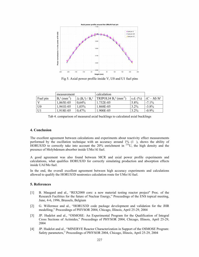
227
Axial power profile around the UMo/Al fuel pin
0.500
0.600
0.700
0.800
0.900
1.000
1.100
-250 -200 -150 -100 -50 0 50 100 150 200 250
Height (mm)
Pow
er n
orm
aliz
ed to
1 in
the
cent
er o
f R1-
UO
2 fuel pin V
fuel pin U0fuel pin U1
Fig 5. Axial power profile inside V, U0 and U1 fuel pins
measurement calculation Fuel pin Bz² (mm-2) Δ (Bz²) / Bz² TRIPOLI4 Bz² (mm-2) s.d. (%) (C – M)/M V 1,865E-05 0,64% 1.732E-05 5.8% -7.1% U0 1,941E-05 1,03% 1.868E-05 3.2% -3.8% U1 1,918E-05 0,47% 1.900E-05 3.2% -0.9%
Tab 4. comparison of measured axial bucklings to calculated axial bucklings
4. Conclusion The excellent agreement between calculations and experiments about reactivity effect measurements performed by the oscillation technique with an accuracy around 1% (1�), shows the ability of HORUS3D to correctly take into account the 20% enrichment in 235U, the high density and the presence of Molybdenum absorber inside UMo/Al fuel. A good agreement was also found between MCR and axial power profile experiments and calculations, what qualifies HORUS3D for correctly simulating production and absorption effects inside UAl/Mo fuel.
In the end, the overall excellent agreement between high accuracy experiments and calculations allowed to qualify the HORUS3D neutronics calculation route for UMo/Al fuel.
5. References [1] B. Maugard and al., “REX2000 core: a new material testing reactor project" Proc. of the
Research Facilities for the future of Nuclear Energy,” Proceedings of the ENS topical meeting, June, 4-6, 1996, Brussels, Belgium
[2] G. Willermoz and al., “HORUS3D code package development and validation for the JHR modelling,” Proceedings of PHYSOR 2004, Chicago, Illinois, April 25-29, 2004
[3] JP. Hudelot and al., “OSMOSE: An Experimental Program for the Qualification of Integral Cross Sections of Actinides,” Proceedings of PHYSOR 2004, Chicago, Illinois, April 25-29, 2004
[4] JP. Hudelot and al., “MINERVE Reactor Characterization in Support of the OSMOSE Program: Safety parameters,” Proceedings of PHYSOR 2004, Chicago, Illinois, April 25-29, 2004

228
[5] JP. Hudelot and al., “Measurement of the modified conversion ratio of 238U by gamma-ray spectrometry on an irradiated fuel pin,” CGS11 Conference, Prague, September 2-6, 2002
[6] C. Döderlein and al., “The VALMONT experimental programme for the neutronics qualification of UMo/Al fuel for the Jules-Horowitz-reactor,” Proceedings of RERTR 2004, Vienna, November 2004

229
CORE CONVERSION STUDY FROM SILICIDE TO MOLYBDENUM FUEL IN THE INDONESIAN 30 MW
MULTIPURPOSE REACTOR G.A. SIWABESSY (RSG-GAS)
T.M. SEMBIRING and I. KUNTORO Center for Development of Research Reactor Technology
National Nuclear Energy Agency (BATAN) Kawasan PUSPIPTEK, Serpong, Tangerang, 15310 - Indonesia
ABSTRACT This paper describes the core conversion from silicide to molybdenum core through a series of silicide (2.96 gU cm-3) - molybdenum (3.55 gUcm-3) mixed transition cores for the Indonesian 30 MW-Multipurpose G.A. Siwabessy (RSG-GAS) reactor. The core calculations are carried out using the two-dimensional multigroup neutron diffusion method code of Batan-EQUIL-2D. The calculated results showed that the proposed silicide-molybdenum mixed transition cores, using the same refueling/reshuffling scheme, meet the safety criteria and it can be used in safely converting from an all-silicide core to an all-molybdenum core.
1. Introduction The equilibrium silicide core of the Indonesian 30 MW multipurpose G.A. Siwabessy (RSG-GAS) was achieved through a series of the mixed oxide-silicide transition cores with the same uranium meat density of 2.96 gcm-3. The fuel management strategy using the mixed cores is chosen due to the nominal power of 30 MWth can be kept as long as the core conversion program. In the core conversion program, the same refueling and reshuffle scheme was also applied for all transition cores, in order to get the efficient and effective core fuel management. To anticipate the program to use molybdenum (U-Mo) fuels instead of sillicide fuels for research reactors, an equilibrium molybdenum core has been designed for RSG-GAS reactor, completely. The previous study showed that the U-Mo fuel with uranium meat density of 3.55 gcm-3 and contains 6 w/o Mo and 9 w/o Mo, can be used and proposed as the candidate of the equilibrium molybdenum cores for RSG-GAS reactor [1]. The equilibrium molybdenum core can be achieved in two ways. The first one is through several smaller transition cores which utilise only higher-loading molybdenum fuel elements. In this case, the reactor power must be reduced during the transition period since the active volume of the transition core is smaller than that of the equilibrium core. The other option, which permits operation at the present nominal power, is through a series of silicide-molybdenum mixed transition cores which use both the present (probably partly burned) silicide fuel elements and higher loading molybdenum fuel elements. Therefore, the main objective of this paper is to obtain the transition cores of the RSG-GAS reactor to convert the core from an all-silicide core to an all-molybdenum core using the silicide-molybdenum mixed transition cores. The disparate study by Suparlina, L. and Sembiring, T.M. [2] showed the equilibrium silicide core with uranium meat density of 3.55 gcm-3 can be achieved by the transition cores using mixed uranium meat densities of 2.96 – 3.55 gcm-3, without changing the refueling and reshuffle scheme. Based on those studies [1-2], we supposed the equilibrium molybdenum core of the RSG-GAS reactor can be safely achieved using silicide (2.96 gUcm-3)- molybdenum (3.55 gUcm-3) mixed transition cores. In this paper the core calculation focus on the equilibrium molybdenum core with 6 w/o Mo (U-6Mo-Al).
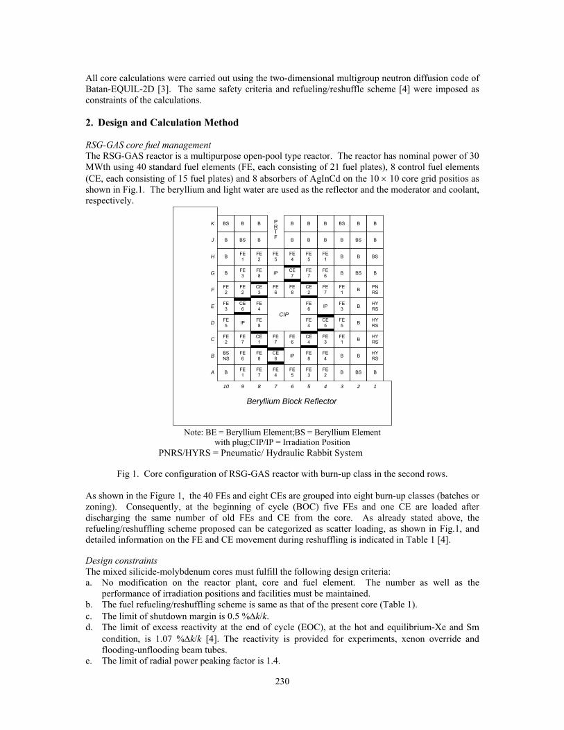
230
All core calculations were carried out using the two-dimensional multigroup neutron diffusion code of Batan-EQUIL-2D [3]. The same safety criteria and refueling/reshuffle scheme [4] were imposed as constraints of the calculations. 2. Design and Calculation Method RSG-GAS core fuel management The RSG-GAS reactor is a multipurpose open-pool type reactor. The reactor has nominal power of 30 MWth using 40 standard fuel elements (FE, each consisting of 21 fuel plates), 8 control fuel elements (CE, each consisting of 15 fuel plates) and 8 absorbers of AgInCd on the 10 × 10 core grid positios as shown in Fig.1. The beryllium and light water are used as the reflector and the moderator and coolant, respectively.
A B FE1
FE7
FE4
FE5
FE3
FE2 B BS B
12345678910
Beryllium Block Reflector
BS B B B B BS B B
B
B
B
FE2
FE3
FE5
FE2
BSNS
BS
FE1
FE3
FE2
CE6
IP
FE7
FE6
B
FE2
FE8
CE3
FE4
FE8
CE1
FE8
FE5
IP
FE6
FE7
CE8
B
FE4
CE7
FE8
FE6
IP
B
FE5
FE7
CE2
FE6
FE4
CE4
FE8
B
FE1
FE6
FE7
IP
CE5
FE3
FE4
B
B
B
FE1
FE3
FE5
FE1
B
BS
B
BS
B
B
B
B
B
B
BS
B
PNRS
HYRS
HYRS
HYRS
HYRS
B
B
C
D
E
F
G
H
J
K PRTF
CIP
Note: BE = Beryllium Element;BS = Beryllium Element
with plug;CIP/IP = Irradiation Position PNRS/HYRS = Pneumatic/ Hydraulic Rabbit System
Fig 1. Core configuration of RSG-GAS reactor with burn-up class in the second rows.
As shown in the Figure 1, the 40 FEs and eight CEs are grouped into eight burn-up classes (batches or zoning). Consequently, at the beginning of cycle (BOC) five FEs and one CE are loaded after discharging the same number of old FEs and CE from the core. As already stated above, the refueling/reshuffling scheme proposed can be categorized as scatter loading, as shown in Fig.1, and detailed information on the FE and CE movement during reshuffling is indicated in Table 1 [4]. Design constraints The mixed silicide-molybdenum cores must fulfill the following design criteria: a. No modification on the reactor plant, core and fuel element. The number as well as the
performance of irradiation positions and facilities must be maintained. b. The fuel refueling/reshuffling scheme is same as that of the present core (Table 1). c. The limit of shutdown margin is 0.5 %Δk/k. d. The limit of excess reactivity at the end of cycle (EOC), at the hot and equilibrium-Xe and Sm
condition, is 1.07 %Δk/k [4]. The reactivity is provided for experiments, xenon override and flooding-unflooding beam tubes.
e. The limit of radial power peaking factor is 1.4.

231
Computational procedure and codes The generation of macroscopic cross-section for molybdenum (U-Mo-Al) and silicide (U3Si2-Al) fuels was prepared with the WIMSD-5B lattice calculation code [5] using the ‘1986’ WIMS Nuclear Data Library [6] in the MTR_PC V2.6 system [7]. The cross-section was prepared in the 4-groups using the structure of the neutron energy boundaries of 10 MeV, 0.821 MeV, 5.531 keV, 0.625 eV and 0. eV. The cross-section was generated as a function of %loss of 235U, uranium meat density, temperature and fission-product poisons (Xe and Sm) condition. The cross-section sets were then arranged in a library for the core calculation. All transition cores were modeled in the 2-dimensional X-Y reactor geometry. The core calculation was carried out using the multigroup neutron diffusion method of the Batan-EQUIL-2D code while the axial buckling was corrected by the 3-dimensional core calculation, the blackness coefficient α (DB), for each neutron energy group, was used in the calculation for the insertion of AgInCd absorbers.
From To From To From To H-9 F-10 F-5 F-8 C-7 B-8 H-8 C-4 F-4 F-6 C-6 G-5 H-7 F-7 F-3 C-10 C-5 D-4 H-6 D-10 E-10 B-4 C-4 D-5 H-5 E-5 E-9 G-6 C-3 H-8 H-4 F-9 E-8 D-3 B-9 C-9 G-9 E-8 E-5 A-8 B-8 out G-8 out E-3 A-7 B-7 out G-6 B-7 D-10 G-4 B-5 out G-5 G-8 D-8 out B-4 A-6 G-4 C-7 D-5 H-5 A-9 A-4 F-10 G-9 D-4 E-9 A-8 B-5 F-9 A-5 D-3 C-6 A-7 H-7 F-8 C-5 C-10 E-3 A-6 B-9 F-7 F-4 C-9 D-8 A-5 H-6 F-6 out C-8 F-5 A-4 E-10
Tab 1. Reshuffling and refueling scheme for the present equilibrium core of RSG GAS. 3. Results and Discussions Table 2 shows an all-molybdenum core is achieved on the eight-transition core (TR-8). It is caused five FEs and one CE are loaded into the core for every operation cycle.
Label of the transition
cores
Number of silicide fuel
(FE/CE)
Number of molybdenu
m fuel (FE/CE)
Operation cycle
length, MWD
ρSM*
(%Δk/k)
Max. discharged
burn-up(%)
Max. Radial PPF
TR-1 5/1 35/7 1093,6 0,97 60,4 1,31 TR-2 10/2 30/6 753,2 1,93 61,4 1,33 TR-3 15/3 25/3 767,5 1,32 62,2 1,32 TR-4 20/4 20/4 922,5 0,96 64,5 1,30 TR-5 25/5 15/3 892,5 1,17 66,2 1,28 TR-6 30/6 10/2 965,2 0,96 68,1 1,27 TR-7 35/7 5/1 1050,0 0,96 71,2 1,26 TR-8 40/8 0/0 1079,2 0,70 69,1 1,27
Note: *)ρSM = shutdown margin
Tab 2. The neutronic calculated parameters for the mixed oxide-silicide cores
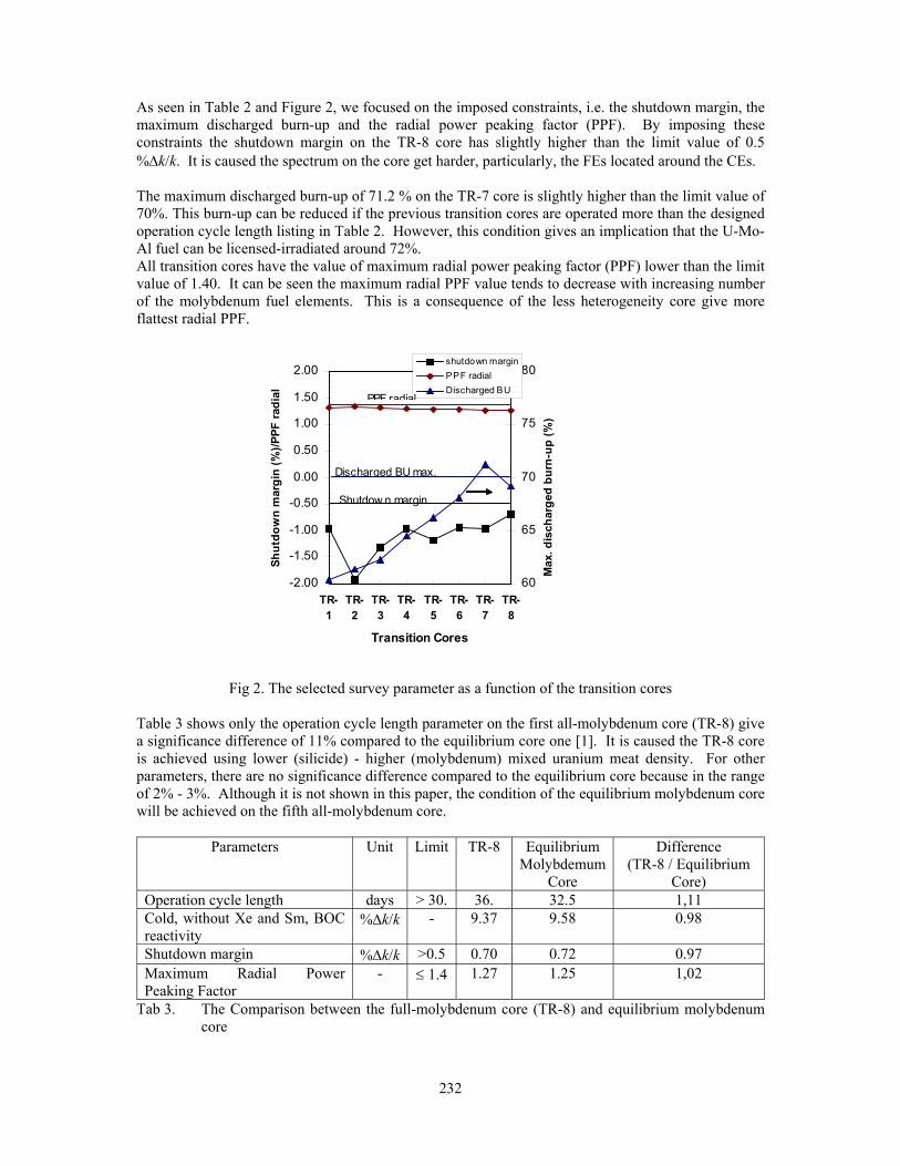
232
As seen in Table 2 and Figure 2, we focused on the imposed constraints, i.e. the shutdown margin, the maximum discharged burn-up and the radial power peaking factor (PPF). By imposing these constraints the shutdown margin on the TR-8 core has slightly higher than the limit value of 0.5 %Δk/k. It is caused the spectrum on the core get harder, particularly, the FEs located around the CEs. The maximum discharged burn-up of 71.2 % on the TR-7 core is slightly higher than the limit value of 70%. This burn-up can be reduced if the previous transition cores are operated more than the designed operation cycle length listing in Table 2. However, this condition gives an implication that the U-Mo-Al fuel can be licensed-irradiated around 72%. All transition cores have the value of maximum radial power peaking factor (PPF) lower than the limit value of 1.40. It can be seen the maximum radial PPF value tends to decrease with increasing number of the molybdenum fuel elements. This is a consequence of the less heterogeneity core give more flattest radial PPF.
-2.00
-1.50
-1.00
-0.50
0.00
0.50
1.00
1.50
2.00
TR-1
TR-2
TR-3
TR-4
TR-5
TR-6
TR-7
TR-8
Transition Cores
Shut
dow
n m
argi
n (%
)/PPF
radi
al
60
65
70
75
80
Max
. dis
char
ged
burn
-up
(%)
shutdown marginPPF radialDischarged BU
Discharged BU max.
Shutdow n margin
PPF radial
Fig 2. The selected survey parameter as a function of the transition cores
Table 3 shows only the operation cycle length parameter on the first all-molybdenum core (TR-8) give a significance difference of 11% compared to the equilibrium core one [1]. It is caused the TR-8 core is achieved using lower (silicide) - higher (molybdenum) mixed uranium meat density. For other parameters, there are no significance difference compared to the equilibrium core because in the range of 2% - 3%. Although it is not shown in this paper, the condition of the equilibrium molybdenum core will be achieved on the fifth all-molybdenum core.
Parameters Unit Limit TR-8 Equilibrium Molybdemum
Core
Difference (TR-8 / Equilibrium
Core) Operation cycle length days > 30. 36. 32.5 1,11 Cold, without Xe and Sm, BOC reactivity
%Δk/k - 9.37 9.58 0.98
Shutdown margin %Δk/k >0.5 0.70 0.72 0.97 Maximum Radial Power Peaking Factor
- ≤ 1.4 1.27 1.25 1,02
Tab 3. The Comparison between the full-molybdenum core (TR-8) and equilibrium molybdenum core

233
4. Conclusion The calculated result showed that the proposed silicide-molybdenum mixed transition cores, for conversion the lower uranium meat density of silicide core to the higher uranium meat density of molybdenum core, using the same refueling/reshuffling scheme, meet the safety criteria. The calculation results proved that the all-molybdenum core can be safely achieved using the proposed mixed transition cores and the neutronic parameters of the core is almost close to the equilibrium molybdenum core’s parameter. 5. References [1] Sembiring, T.M., Kuntoro, I., Taryo, T., Preliminary Study on the Utilization of U-Mo Fuel for
RSG-GAS Reactor, Trans. Intl. Conf. Research Reactor Fuel Management (RRFM 2004), Munich, Germany, March 21-24, 2004
[2] Suparlina, L. and Sembiring, T.M., The Arrangement of RSG-GAS Equilibrium Silicide 300 G Core by 250 G and 300 G Mixed Core, Proceeding of The 7th Nuclear Power Plant and Nuclear Facility Technology and Safety Seminar, Bandung, Indonesia, February 19, 2002 (in Indonesia)
[3] Liem, P.H., Development of an In-Core Fuel Management Code for Searching the Equilibrium Core In 2-D Reactor Geometry (Batan-EQUIL-2D), Atom Indonesia 23, 2 (1997)
[4] Liem, P.H., et al., Fuel Management Strategy for the New Equilibrium Silicide Core Design of RSG GAS (MPR-30), Nuclear Engineering and Design 180 (1998), p. 207-219
[5] Answer Software Service AEA Technology, WIMSD-5B: Determenistic Code System for Reactor-Lattice Calculations, Winfrith, United Kingdom (1999).
[6] Halsall, M.J. and Taubman, C.J., The ‘1986’ WIMS Nuclear Data Libarry, United Kingdom Atomic Energy Agency, Winfrith, United Kingdom (1986).
[7] Villarino, E.A., MTR_PC v2.6 System, INVAP, Argentina.
234
PROGRESS OF ACTIVITIES WITH REGARD TO RECONSTRUCTION OF THE RESEARCH REACTOR IRT –
SOFIA
T. APOSTOLOV, E. ANASTASOVA, D. DRENSKI, V. ANASTASOV, A. STOYANOVA, E. MOSKOV, S. BELOUSOV, S. KADALEV
Nuclear Scientific Experimental Centre, Institute for Nuclear Research and Nuclear Energy,
72, Tzarigradsko chausse, Sofia 1784, Bulgaria
and
L. MANEV, M. BALTIYSKI Atomenergoproekt Ltd,
51 James Bauchier, Sofia 1407, Bulgaria
ABSTRACT The strategy for the Research Reactor IRT-Sofia, after decision of the Government for its reconstruction, is a partial dismantling of the old systems and equipment, conversion of the new fresh nuclear fuel and transportation of the spent fuel to Russia. Removal of the reactor core and replacement of old equipment will not pose any significant problems for dismantling. For most efficient use of resources there is a need for implementation of the engineering project, “General plan for partial dismantling of equipment of the IRT-Sofia as a part of the reconstruction into low power RR”, which has been already prepared. The new research reactor IRT-Sofia is jointly studied with the RERTR Program at Argonne National Laboratory /ANL/ to examine the feasibility of conversion from the use of fuel containing highly enriched uranium /HEU, 36 % 235U/ to use of fuel containing low enriched uranium /LEU, 19,7 % 235U/. Other important task connected with the reconstruction is shipment of the spent nuclear fuel (EK-10 and C-36 type) to Russia.
1. Introduction GENERAL PLAN FOR PARTIAL DISMANTLING OF RESEARCH REACTOR IRT-SOFIA PRIOR TO ITS RECONSTRUCTION INTO LOW POWER REACTOR On the basis of [1] and the General plan for partial dismantling of the reactor and its systems it was specified that the reconstruction shall comprise the following reactor systems:
• Core – liable to full scale replacement. The new core loading shall be pursuant with the type of the new converted (low enriched) fuel (IRT-4M type 20 % enrichment).
• Primary cooling system – replacement of the aluminum lining of reactor pool of 60 m3
capacity, piping and fitments, as well as the heat exchangers. • Secondary cooling system – partial replacement of piping and fittings and the cooling open-air
pools. • Horizontal experimental channels – their number shall be reduced from the existing 11 to 7
and a new channel is to be set for boron neutron capture therapy. • Spent fuel storage – replacement of the aluminum reservoir of 12 m3 capacity • Electric power supply (EPS)- full scale replacement of cables and equipment • Control and Protection System (CPS)- full scale replacement of cables and equipment

235
• Radiation Monitoring and Dosimetry System (RMDS)- full scale replacement of measuring lines and equipment
• Civil Engineering Part - new rooms in the main reactor hall are planned to provide for installation of the main control panels and desks of the reactor
• Heating and Climatic Systems – new systems shall be built and installed • Ventilation Systems – partial reconstruction
The disassembly of these systems will be within the capability of the operator organization – (INRNE) with support from contractors, to provide tools and skills, required for size reduction, handling and transportation of the wastes. The General plan for partial dismantling identifies the roles, chain of commands and responsibilities within the dismantling team, and also defines the interfaces with the supporting organizations involved on the INRNE site and supporting sub-contractors. PROVIDING OF SAFETY AND SECURE SPENT NUCLEAR FUEL TRANSPORTATION FROM IRT - SOFIA SITE. PROCEDURES FOR OBTAINING OF LICENCE Current report is also focused on one of the priority goals stipulated in Bulgarian Governmental Decision # 332 from May 17, 1999 – removal of spent nuclear fuel (SNF) from IRT- Sofia site and its exporting for reprocessing and/or for temporary storage on NPP Kozloduy site. Readiness of the Bulgarian Government to implement this decision was additionally supported by the “Strategy for management of spent nuclear fuel and radioactive waste” issued in the year 2004 concretely stipulating the actions required for its implementation. By signing of international conventions [2, 3 and 4] related to the safe SNF transportation, the Republic of Bulgaria committed itself to harmonize its secondary legislation both with the international documents and these ones of EU. Current document stipulates the main provisions required for issuing of permit for transportation of such fuel in compliance with the Bulgarian secondary legislation updated recently. Main requirements in view of the nuclear safety related to the SNF transportation are regulated in [5, 6 and 7]. In these documents the main attention is paid to the technical characteristic of transportation means and equipment. Requirements stipulated in them are in conformity with these ones set out in the recommendable [9 and 10] as well as in the mandatory [11] documents of IAEA. Requirements related to the physical protection during the transportation of nuclear material are determined in [8]. Current common practice is to prepare technical documents needed for granting of permit for SNF transportation specially elaborated and approved by competent State bodies. These documents are not norms and rules but they are directed to solve some concrete cases. Present updated secondary legislation [12 and 13] establishes concrete requirements to the granting of permit for transportation of nuclear material. List of documents required when applying for execution of this activity are enclosed hereto, including administrative acts issued by the respective competent bodies for approval of transportation packing. Lists include:
• Different certificates and evidences related to the applicant; • Documents in view of nuclear material; • Documents related to the transportation and technical means used for its execution; • Program for nuclear safety and radiation protection during the implementation of the
activities; • Documents, related to the staff involved in the transportation activities; • Documents regulating the relationships between the Shipper and Recipient of the goods as
well as between the Applicant and Subcontractors. Also, the secondary legislation stipulates the conditions for issuing, amendment, renewal and termination, revocation and control of these licences and permits. When elaborating the documents required for obtaining of permit the most important are the criteria for selection of optimum transportation scheme for SNF transportation. The main ones of these criteria are as follows: technical, political and economic.

236
Concerning the technical criteria the effective secondary legislation mostly establishes the restrictions and provides sufficiently clear instructions for elaboration of needed investigations and analysis proving the capability for safety transportation of this fuel. Economic criteria as well as their application are banal ones and the only problem faced is to consider precisely all factors forecasting the change of their impact during the process. In view of the political criteria it is well known that the former social and political system in the Eastern European Countries practically did not require consideration of both internal and external political situation. Situation changed in the recent 15 years requires consideration of the impact of internal factors (influence of ecological movements, public opinion both entirely and in separate regions etc.) as well as of foreign political relationships and (in addition) of the internal situation in foreign states. It is not valid only for the neighbour countries but is also effective worldwide. The conclusion could be made that currently in the Republic of Bulgaria there is secondary regulation clearly regulating the transportation of SNF from IRT-Sofia, both in the territory of the country and in case of international transportation. PROGRESS OF CONVERSION FROM HEU TO LEU FUEL AT IRT-200, SOFIA The new 200 kW IRT-Sofia research reactor of the Institute for Nuclear Research and Nuclear Energy (INRNE) of Bulgarian Academy of Science Sofia, Bulgaria is jointly studied with the RERTR Program at Argonne National Laboratory (ANL) to examine the feasibility of conversion from the use of fuel containing highly enriched uranium (HEU, 36% 235U) to use of fuel containing low enriched uranium (LEU, 19.75 235U). The reference design had a core configuration using 14 IRT-2M fuel assemblies (four 4-tubes and ten 3-tubes) with 36% HEU. This HEU fuel is no longer available since it was transported from Bulgaria to Russia in December 2003 as part of an agreement with the US DOE and IAEA. An LEU core configuration using 14 IRT-4M fuel assemblies (four 8-tubes and ten 6-tubes) which yields a similar flux performance when compared with the HEU design was created. Results of detailed calculations comparing the new LEU core with the reference HEU core design are presented. From these results it is concluded that the LEU core performance (both in term of fluxes for the experiments, fuel consumption and temperature solution) is very similar to the HEU reference core. 2. Brief description of contents of material characterization process and measurements in the developed General plan for partial dismantling of IRT – Sofia: RADIOLOGICAL CHARACTERIZATION ACTIVITIES DESCRIPTION
• Characterization program includes the following steps: • Review of historical information • Calculation methods implementation • Sampling and analyses plan preparation
- Characterization of activated materials - Samples and smears taking and implementation of measurements in the reactor vessel - Samples and smears taking and implementation of measurements in premises 103 \first
cooling circle\ - Results from smears and samples - Solid RAW, Toxic materials, Non radioactive materials and Liquid radioactive wastes
• Measurements sampling and analyses performance • Review, evaluation and comparison of data obtained
MEASUREMENTS, SAMPLING AND ANALYSES PERFORMANCE The performance of the Sampling and analyses plan includes measurements before draining of the water of the first cooling circle and measurements, taking smears and samples after empting the water.

237
EXPECTED AMOUNTS OF RAW AT THE PARTIAL DISMANTLING OF IRT-SOFIA EQUIPMENT
І. Expected amounts of RAW – II category according [14]. 1. Aluminium and aluminium alloys from the reactor pool - 1100 kg. 2. Steel Sт 1Х18Н9Т + Al alloy АВ from the reactor pool - 170 kg 3. Shield of the thermal colomn corpus – cassing of St 3,
filled up with paraffin and boron carbide: - St 3 - 289 kg; - paraffin with density1 g/cm3 - 210 kg; - Boron carbide with density1,5 g/cm3 - 60 kg 4. Lead slab - Pb + Al - 211 kg 5. Graphite assemblies from the deflector of RC - 172 kg 6. Ion-exchange resin - 320 kg 7. According previous measurings, quoted in section 1, it is expected approximately 1000 kg of the
thermal column graphite to be activated and to be classified in this category. Expected average activity - 108 Bq/kg In addition: Contaminated materials from І CL/Аl and St/ from І CL - 3780 kg
It is expected after performing of suitable deactivation the materials of I CL to be converted in RAW of I category or in non radioactive wastes. ІІ. Expected amounts of RAW – I category, or non radioactive wastes according [14]. 1. The concrete shielding of thermal column – concrete with density 4,5 t/m3 -5,5m3; 24831 kg (part of the concrete, situated moste near to RC is expected to be volume activated and to pass in upper category waste, according to the classification for RAW) 2. Block with shutters of the thermal column – St3 -5033 kg
Note: For RAW is defined the β и γ activity to be in Bq/kg и Bq/cm2, because it is measured that RAW do not contain long-lived α – radio nuclides with specific activity over 4.10 6 Bq/kg.
238
3. References
[1] Reconstruction of Reactor IRT-2000 at INRNE-BAS to a Low Power Reactor
[2] Joint Convention on the Safety of Spent Fuel Management and on the Safety of Radioactive Waste, promulgated in SG, # 63 dated 18 June 2001.
[3] Convention on the Physical Protection of Nuclear Material, promulgated in SG # 44 dated 9 June 1987.
[4] Vienna Convention on Civil Liability for Nuclear Damage, promulgated SG # 76 dated 20 September 1994.
[5] Regulation #46 for Transportation of Radioactive Waste issued by the Minister of Public Health and by the Chairman of Committee for Safety Use of Atomic Energy promulgated SG # 53 dated 2 July 1976.
[6] Regulation # 46 for Railway Transportation of Dangerous Loads, promulgated SG # 107 dated 11 December 2001.
[7] Regulation for the Basic Norms Radiation Protection promulgated SG # 73 dated 20 August 2004.
[8] Regulation for Provision of Physical Protection of Nuclear Facilities, Nuclear Material and Radioactive Substances, promulgated SG # 77 dated 3. September 2004
[9] IAEA Safety Standards Series “Advisory Material for the IAEA Regulations for the Safe Transport of Radioactive Material”, Safety guide No. TS-G-1.1 (ST-2), Vienna 2002.
[10] IAEA Safety Standards Series “Planning and Preparing for Emergency Response to Transport Accidents Involving Radioactive Material”, Safety guide No. TS-G-1.2 (ST-3), Vienna 2002.
[11] IAEA Safety Standards Series “Regulations for the Safe Transport of Radioactive Material” 1996 Edition (As Amended 2003), Safety Standards Series No. TS-R-1, Vienna 2004.
[12] Act on the Safe Use of Nuclear Energy, promulgated SG # 63 dated 28 June 2002.
[13] Regulation for Procedure for Issuing of Licences and Permits for Safe Use of Nuclear Energy, promulgated SG # 41 dated 18 .May 2004.
[14] Regulation for safe Management of Radioactive Waste, promulgated SG # 72 dated 17.08.2004.

239
WWR-M REACTOR FUEL ELEMENTS AS OBJECTS OF PERMANENT STUDY AND
MODERNIZATION
G. A. KIRSANOV, K. A. KONOPLEV, A.S. POLTAVSKI, A.S. ZAKHAROV
Department of Reactors Physics and Techniques Petersburg Nuclear Physics Institute
188300, Gatchina, Russia ABSTRACT
Brief description of WWR-M5 thin-walled fuel elements and review of possible improvement of parameters for reactor type WWR-M and WWR-SM during transition from fuel elements HEU and LEU WWR-M2 to LEU WWR-M5 is presented.
1. MAIN FEATURES OF WWR-M5 FUEL An increasing of research scope at the WWR-M reactor set the reactor engineers a task to increase the reactor’s productivity, i.e. to raise the neutron flux in experimental channels. Reactor was designed for 10 MW power. Created at the end of 1950s, domestic fuel assemblies consisting of tubular seamless fuel elements had significant thermophysical margin, which allowed to increase the reactor power systematically even at the first years of its operation. By 1966, the steady-state reactor power was raised to 16 MW. A test increasing of power even to 18 MW took place. The thermal and hydraulic research [1, 2] performed in 1970s has allowed to draw the conclusions that the possibilities of further increase the reactor’s specific power by using of fuel assemblies of the WWR-M2 type have already been exhausted. The maximal fuel element clad temperature has already reached the saturation temperature; and although the margin to the critical thermal load was still sufficiently large (> 2,5), any further increase of power and, consequently, the neutron flux density, in this case, caused the appearance of nucleate boiling on the fuel element surface. Therefore, opportunities to increase the specific thermal power by means of changing fuel element design have been investigated.
For the WWR-M reactor conditions, the optimal combinations of the fuel elements thickness and the gap between them have been determined for various number of the fuel elements in the fuel assembly by the conservation of elementary cell dimensions, i.e. without changing the design of support plate and the beryllium reflector [3,4]. The final choice was the 6-element assembly with the fuel element thickness of 1.25 mm and the gap of 1.5 mm. The overall dimensions of cell boundary have remained as same as WWR-M2
The new type of fuel element provided an increase of the specific heat-transfer surface by 1.8 times, that under some decreasing of coolant velocity , gave the gain in the specific thermal power by 1.5 times while conservation of previous limitation on the fuel element clad temperature. The stem design of the fuel assemley provides equal cooling velocity of all fuel elements and record specific heat-transfer surface in the core equals to 6.6 1/cm is achieved.
We began with about the same uranium loading as WWR-M2 fuel. Later on the fuel loading was almost increased twice as much. It reduced the fuel component of operational expenses and raised the multiplication factor of the active core.

240
WWR-M2 assembly
33.5
33. 5
WWR-M5 assembly1)-cap, 2)- rim, 3)-fuel elements, 4)- stem
1.25
0.36
2.5
2.5
0.9
0.72
Fuel: U-Al alloy
WWR-M5 assemblybased on U-Al alloy
WWR-M5 assembly based on UO2
Evolution of crosssection:
cladding
fuelmeat
Fuel: UO2+ Al
(LEU variant ofWWR-M2- WWR-SM)
1.25
0.43
1.25
0.43
750
500
3 2
3 5
cellboundary
A
В
C
Fig. 1 WWR-M5 assembly and elements.

241
After going over to the WWR-M5 the reactor power was increased up to 18 MW in spite of the reduction of the number of fuel assemblies in the core from ≈ 200 to ≈ 130. The increase of the total and specific reactor power was accompanied by the neutron flux growth in the experimental channels. Besides that the additional experimental devices were placed in the released core cells. The experimental device loaded practically every second core cells.
In the process of transition to fuel assembles of the WWR-M5 type, its comprehensive tests were performed up to operation under spiking specific loads up to 900 kW/l, that is a record for fuel elements of pool-type research reactors [5].
Seamless tubular fuel elements enable to shape a reactor core without loss of volume for structural components. Covers of fuel assemblies for fuel rods and side plates of fuel plate assemblies substantially reduce useful volume of reactor core, thus reducing neutron fluxes applicable for experiment.
Only two types of reactor cores are known, which are free from structural components, namely: reactor cores loaded with tubular fuel elements and reactor cores consisting of a mono type block, fabricated from fuel plates. The first type includes multi-purpose reactors, for example: WWR-М, IRT, IVV-2M and the second type: research beam reactors ILL and FRMII. The latter two are solely intended for extraction of high-density neutron beams and have no irradiation devices within reactor core. In both types, specific heat-emitting surface of fuel elements and reactor core as a whole match with each other.
2. WWR-M5 FUEL ASSEMBLIES FOR WWR-M and WWR-SM REACTORS CONVERSION We compared reactor cores for reactor type WWR-М during application of LEU WWR-M2 and WWR-M5 fuel elements. The calculations were performed under the MCNP-4C code. Simplified burnup model with one stable fission product was used. Possible burnup in discharge fuel is equal about 55-60 % in both cases.
For LEU WWR-M5 based on uranium dioxide we used uranium density in the matrix approximately 3g/cm3. For LEU on UМo basis - approximately 5.5 g/cm3. Geometry of fuel elements in both cases preserved: thickness of nuclear fuel layer 0.39 mm and cladding 0.43 mm. Therefore, fuel assemble loading by U-235 for active layer height 500mm was approximated to 42 and 72 g. Certain increase of loading is possible after an increase of fuel layer thickness due to reduction of cladding thickness. Application of uranium dioxide in WWR-M5 fuel elements gives only heat- emitting advantages , e.g., factor of non-uniformity of energy release KV may be increased from 3 to 5. Heat-emitting advantages can hardly repay increased fuel expenses during transition from 3 to 6 fuel elements assembly.
Application of UМo in WWR-M5 fuel elements enables to increase the volume of experimental devices within reactor core. For example, we present charts of probable loading for WWR-M reactor core with WWR-M2 and WWR-M5 fuel elements (fig.2 and3).
Evidently, transition for UМo of WWR-M5 fuel element doubles the number of channels for radiation within reactor core. This calculation is made as an example of opportunities only, which may be achieved during application of WWR-M5 fuel elements. As far as other reactors and other tasks are concerned, loading will be different, but in all cases UMo-based WWR-M5 will give noticeable advantage vs UO2-based HEU and LEU WWR-M2 fuel elements in all cases with equal reactivity margin.
Development of LEU WWR-М5 fuel elements to replace WWR-M2 enables to improve the quality of reactors in Budapest and Kiev vs. existing HEU WWR-M2 fuel elements.
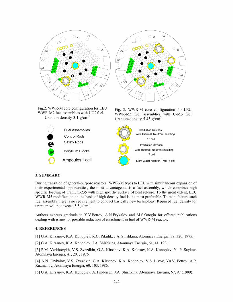
242
V1 V2
V3
V4
V5
V8
V7 V6
V9
V10
V11
V12
V13
Be
Be BeBeBe
Be BeBeBe
Be BeBe
Be Be
Be
Be
Be
Be
BeBe Be
BeBe
Be
V1 V2
V3
V4
V5
V8
V7 V6
V9
V10
V11
V12
V13
Be
Be BeBeBe
Be BeBeBe
Be BeBe
Be Be
Be
Be
Be
Be
BeBe Be
BeBe
Be
Fig.2. WWR-M core configuration for LEU WWR-M2 fuel assemblies with UO2 fuel. Uranium density 3,1 g/cm3
Fig. 3. WWR-M core configuration for LEU WWR-M5 fuel assemblies with U-Mo fuel Uranium density 5.45 g/cm3
Fuel Assemblies
Be
Control Rods
Beryllium Blocks
Safety Rods
Ampoules1 cell
Irradiation Deviceswith Thermal Neutron Shielding
Light Water Neutron Trap
12 cell
Irradiation Devices
with Thermal Neutron Shielding
7 cell
7 cell
3. SUMMARY During transition of general-purpose reactors (WWR-M type) to LEU with simultaneous expansion of their experimental opportunities, the most advantageous is a fuel assembly, which combines high specific loading of uranium-235 with high specific surface of heat release. To the great extent, LEU WWR-M5 modification on the basis of high-density fuel is the most preferable. To manufacture such fuel assembly there is no requirement to conduct basically new technology. Required fuel density for uranium will not exceed 5.5 g/cm3. Authors express gratitude to Y.V.Petrov, A.N.Erykalov and M.S.Onegin for offered publications dealing with issues for possible reduction of enrichment in fuel of WWR-M reactor. 4. REFERENCES [1] G.A. Kirsanov, K.A. Konoplev, R.G. Pikulik, J.A. Shishkina, Atomnaya Energia, 39, 320, 1975.
[2] G.A. Kirsanov, K.A. Konoplev, J.A. Shishkina, Atomnaya Energia, 61, 41, 1986.
[3] P.M. Verkhovykh, V.S. Zvezdkin, G.A. Kirsanov, K.A. Kolosov, K.A. Konoplev, Yu.P. Saykov, Atomnaya Energia, 41, 201, 1976.
[4] A.N. Erykalov, V.S. Zvezdkin, G.A. Kirsanov, K.A. Konoplev, V.S. L’vov, Yu.V. Petrov, A.P. Ruzmanov, Atomnaya Energia, 60, 103, 1986.
[5] G.A. Kirsanov, K.A. Konoplev, A. Findeisen, J.A. Shishkina, Atomnaya Energia, 67, 97 (1989).

243
CERCAS FUEL ELEMENTS INSTRUMENTATION MANUFACTURING
G. HARBONNIER, C. JAROUSSE, T. PIN, M. FEBVRE, P. COLOMB
AREVA / CERCA Z.I. Les Berauds, 26104 Romans, France
ABSTRACT When research and test reactors wish to further understand the Fuel Elements behavior when operating as well as mastering their irradiation conditions, operators carry out neutron and thermo hydraulic analysis. For thermal calculation, the codes used have to be preliminary validated, at least in the range of the reactor safety operational limits. When some further investigations are requested either by safety authorities or for its own reactor needs, instrumented tools are the ultimate solution for providing representative measurements. Such measurements can be conducted for validating thermal calculation codes, at nominal operating condition as well as during transients ones, or for providing numerous and useful data in the frame of a new products qualification program. CERCA, with many years of experience for implanting thermocouples in various products design, states in this poster his manufacturing background on instrumented elements, plates or targets.

244
BURNUP MEASUREMENTS OF LEU FUEL FOR SHORT COOLING TIMES
C. PEREDA B., C. HENRÍQUEZ A., J. KLEIN D., J. MEDEL R. Comisión Chilena de Energía Nuclear
Amunátegui 95, Santiago, Chile.
ABSTRACT The measurements presented in this work were made essentially at in-pool gamma-spectrometric facility, installed inside of the secondary pool of the RECH-1 research reactor, where the measured fuel elements are under 2 meters of water. The main reason for using the in-pool facility was because of its capability to measure the burning of fuel elements without having to wait so long, that is with only 5 cooling days, which are the usual times between reactor operations. Regarding these short cooling times, this work confirms again the possibility of using the 95Zr as a promising burnup monitor, in spite of the rough approximations used to do it. These results are statistically reasonable within the range calculated using codes. The work corroborates previous results, presented in Santiago de Chile [1], and it suggests future improvements in that way.
1. Introduction In the near future, the RECH-1 research reactor will be completely converted to the use of LEU (19.75% of 235U) fuel. The current reactor core loads 22 HEU (45% of 235U) fuel assemblies fabricated by the UKAEA in Deanery, Scotland, and 12 LEU fuel assemblies fabricated by the Chilean Fuel Fabrication Plant (PEC). The meat composition of the experimental LEU fuel assembly is U3Si2-Al, whereas the HEU fuel assemblies have a meat composed by UAlx-Al. The first two LEU fuel assemblies were loaded in the reactor core in December 1998, and the second two in July 1999. LEU fuel assemblies have been gradually loaded in the core to replace HEU fuel assemblies which have reached the discharged burn-up. The total conversion of the RECH-1 reactor will be achieved during the first semester 2006. The first four LEU fuel assemblies loaded in the reactor core are supporting a local qualification program to know the behavior under irradiation of fuel assemblies fabricated by the PEC. In order to measure the fuel burn up of irradiated fuel assemblies, the CCHEN has two completely independent facilities using gamma spectroscopy technique: a hot cell facility and an in-pool facility described in earlier works [1],[2]. The first facility is mainly used to measure burn up of spent fuel assemblies with decay periods larger than three months. With the purpose to measure burnup of fuel assemblies with shorter decay periods, it was decided to build an in-pool facility. The measurement of burnup using gamma spectroscopy technique after long decay period is very well known and 137Cs as monitor gives reliable results[2],[3],[4],[5]. However, the same measurement with short decay periods (few days) produces serious difficulties in the treatment of the collected experimental data. The origin of these difficulties is the high activity generated by a large number of fission products of short life time, which increases the dead time and background reducing the quality of the statistics of the monitor [6], and in our experience submerging completely the 137Cs under the background radiation, even with 4 months operation and 5 cooling days. Monitors like 95Zr, 140La, 103Ru, 95Nb, etc. have good statistics; however, they have too short life to keep the accumulated burn up for long irradiation time. The burn up of one fuel assembly of the RECH-1 research reactor with short decay period was measured at the in-pool facility using 95Zr (724 keV, peak) as monitor in 2003 [1]. The methodology presented in this paper should be taken as a verification of our first attempt to use 95Zr as a monitor.

245
2. Measurements and results First of all, a full re-evaluation of utilized numbers of our cited previous work [1], was made including a refinement of basic burnup algorithm [3], [4], taking into account the differences of fuel density between external and internal plates of our fuel assemblies, more precise geometric measurements of in-pool measuring system, recalculation of gamma attenuation coefficients involved, and the use of new values of average fission yields adapted to the real operational conditions of RECH-1, an essentially thermal reactor [7]. The outcomes are showed in Table 1 where sub-index 1 and 2 represent the old [1] and new values, as much for 95Zr as for 137Cs. We used essentially the same simple physical assumptions and basic values to formulate the factor F in [1] for 95Zr except for a generalization that includes the possible non routine decay times. As it is known, this factor is needed to compensate for cumulative decay of 95Zr occurring during the different irradiation periods between the measurement and the relevant initial core operation. For 137Cs, a similar f factor is known for a long time [3],[4],[5],[8]. Then, the refined expression for F is:
1( 1 ) (1)−− −⎡ ⎤= + + − − −⎣ ⎦TTF k e p k pe e λλτ λ ,
where, k: total numbers of reactor operations, τ: time between operations, T: maintenance period, and p: number of maintenance periods while the fuel assembly was in the reactor core.
λ: 95Zr Disintegration Constant. T1: non routine decay time.
Fuel Assembly Identification
Date of Measurement
Decay Period Days and Monitor
Burnup1 %
Burnup2 %
Calculated Burnup
% LR-04L 30-Jan-03 5 (95Zr) 27.88 29.08 22.78 LR-04L 13-Mar-03 5 (95Zr) 23.68 24.29 23.00 LR-04L 12-Jun-03 5 (95Zr) 25.08 25.13 24.52 LR-04L 24-Sep-03 53 (137Cs) 22.75 25.35 25.40
Table 1. Measured burnup results obtained for the LR-04L fuel assembly using 95Zr and 137Cs (at fourth row) as monitors, refined in column2 and explained in the text, compared with Citation code results (fifth column). Two LEU assemblies made by the PEC were measured during January of 2005; the LR-47 which has nearly 5 months in core, and again (to follow its behaviour) the LR-04L, that in the moment of measuring has nearly 66.5 months in operation. Additionally, this last assembly had an intermediate decay interval of 209 days specifically made to use 137Cs in measuring the burnup of it, and therefore to have a more reliable result to compare. The LR-04L was taken from the core on 2 August 2003, was measured on 24 September 2003 (see Table 1), and returned to the core on 27 February 2004, and continues in operation until now. The following two tables, show the relevant results using the aforementioned factor F, and two different ways to evaluate the burnup of LR-04L: (i) The first way, presented in Table 2, consists in repeating the already known procedure [1] taking into account in F, that T1 = 209 days for LR-04L. Table 2 includes, besides the result for LR-47 whose operational conduct is much more simple, therefore not requiring the second proposed way.

246
Fuel Assembly Identification
Date of Measurement
Decay Period, Days
Burnup(Zr –95) %
Calculated Burnup %
LR-04L 13-01-05 5 25.16 29.98 LR-04L 20-01-05 5 29.07 29.98 LR-47 27-01-05 5 2.44 1.95
Table 2. Burnup results obtained for two LEU assemblies measured in January 2005, with the same refinements than Table 1 and using first evaluation way. The calculated burnup using Citation code, corresponds to 17/01/05(fifth column). (ii) The second evaluation way, used only in LR-04L for comparison reasons, measures the burnup of this fuel element from the first day it was put on the core again (27/02/04) until the measurement dates. This is equivalent to suppose that it is fresh, or that P, T and T1 in (1) are zero. Then the real burnup is obtained adding this number to the previous burnup measured of LR-04L with 137Cs, whose refined value (25.35%) is in Table 1. The outcomes of this addition is showed in the fourth column on Table 3.
Fuel Assembly
Identification
Date of Measurement
Decay Period, Days
Burnup(Zr –95) as fresh element
%
Actual Burnup adding the Table 2
%
Calculated Burnup %
LR-04L 13-01-05 5 5.57 30.92 29.98 LR-04L 20-01-05 5 6.52 31.87 29.98
Table 3. Burnup results for the same LR-04L assembly in table 2, using now the burnup results of 24/09/03, with 137Cs monitor showed in Table 1 as zero reference and explained in text, compared with CITATION code outcomes corresponds to 17/01/05.(fifth column). The full results of the two described ways of measuring are showed in Graph 1. The averaged differences used in graph are given by:
Averaged Diff.= ( )1 c 2 c1 B B B B (2),2
− + −
where, B1: Measured percentage Burnup with 95Zr , by first evaluation way. B2 : Measured percentage Burnup with 95Zr , by second evaluation way. BC: Calculated percentage Burnup. The averaged difference is used because of the differences between the burnup measurements dates and the calculated burnup date, not allow to make a precise comparison date to date.
Comparative measurements for LR-04L, with Zr95 and codes. Year 2005
0
10
20
30
40
Meas. 13/01 Meas. 20/01 Code 17/01 AveragedDifference
Perc
enta
ge B
urnu
p
Firstevaluationway
Secondevaluationway
Graph 1
2.87 1.42%

247
3. Conclusions -Considering the simplicity of the physical assumptions used to formulate F, and the supposed periodical operation of RECH-1 used on the algorithm to calculate F, the results are promising. The tables show that the averaged differences between the measured burnup and the codes or calculated burnups, are lower if the assembly operational biography is simpler. Similar conclusion is obtained from measurement of the LR-47 assembly. Then, the results using 95Zr are reasonably within the range calculated using codes. -The measurements confirm that 137Cs is a very reliable burnup monitor even with nearly 50 days cooling period. -Due to the unavoidable non periodic operation of the RECH-1 and to the relatively short life of 95Zr, the obtained results with this monitor have unavoidable variability, too. It is seen specially in the interoperation measured burnup results. The actual behavior of operation conspire against the simplicity of the algorithm. -Three possible improvements (in increasing order of importance) are suggested in algorithmic and experimental fields: (i) Algorithmic: Take into account the actual power history of RECH-1 reactor in a very much detailed way, as with the 137Cs monitor. It is possible that the hypothetical benefit in precision could be smaller than the loss in the simplicity of the present F. (ii) Experimental: The HPGe detector must be fixed to the mechanical measurement system, due to the fact that it produces important variations in activity measurements, which only contributes to increase the uncertainty in the efficiency of system. (iii) Experimental and Algorithmic: It is necessary to make continuous measurements during a sufficient time (3 or 4 months) for a specific LEU assembly, in order to improve the empirical knowledge of 95Zr behavior, between and in routine reactor operations. 4. Acknowledgements The authors wish to express their gratitude to Dr. A. Kestelman, from Bariloche Atomic Center, Argentina, for his scientific assistance in the great challenge to measure fuel burnup using spectrometry technique. We thank also to the operation team of RECH-1 research reactor for its support during the measurements. 5. References [1] C. Pereda, C. Henríquez, J. Medel, J. Klein, and A. Kestelman, “Fuel Burnup Measurements Using
Gamma Spectrometry Technique”, ICRR 2003, Santiago de Chile, November 2003. [2] C. Henríquez, G. Navarro, C. Pereda, H. Torres, L. Peña, J. Klein, D. Calderón, and A. J.
Kestelman, “Burnup Measurements at the Rech-1 Research Reactor”, RETR 2002, November 2002, Bariloche, Argentina.
[3] C. Henríquez, G. Navarro, C. Pereda, and G. Steinman, “Medición de Quemado de un Elemento
Combustible Experimental Mediante Espectroscopía Gamma”, Nucleotécnica, 35, 71-83, 2001. [4] L.A.A. Terremoto, C.A. Zeituni, J.A. Perrota, and J.E.R. Da Silva, “Gamma-ray spectroscopy on
irradiated MTR fuel elements”. Nucl. Instr. Meth. A 450(200) 495-514. [5] A. J. Kestelman and S. Ribeiro Guevara, “Determinación del Quemado en Combustible tipo MTR
Mediante Espectrometría Gamma con Cristal de INa (Tl)”, Informe Técnico CNEA-CAB 88/034. [6] Debertin K. And Helmer R., “Gamma and X-Ray Spectrometry with Semiconductor Detectors”,
North Holland, 1988.
248
[7] Baard J.H., Zijp W.L. and Nolthenius H.J., “Nuclear Data Guide for Reactor Neutron Metrology”,
Kluwer Academic Publishers, 1989. [8] P.Suárez and A. Kestelman, “Determinación no destructiva del quemado en elementos combustible
tipo MTR mediante espectroscopía gamma de alta resolución”, Memoria de Título, Instituto Balseiro Universidad Nacional de Cuyo, CNEA, Junio 1989.

249
ETRR-2 IN-CORE FUEL MANAGEMENT STRATEGY
M.Y. KHALIL PhD, Professor of Nuclear Engineering
Department of Nuclear Engineering, Alexandria University Alexandria, Egypt
ESMAT AMIN
National Center for Nuclear Safety and Radiation Control Atomic Energy Authority
El Zohoor District, Nasr City, Cairo, Egypt
and
M.G. BELAL Egypt Second Research Reactor
Atomic Energy Authority, Inshas, 13579, Egypt
ABSTRACT 1. Introduction The ETRR-2 core consists of an array of 6x5 with 29 fuel elements and a central irradiation position. In order to determine the fuel management strategy, a lot of variables and boundary conditions should be studied simultaneously. WIMSD4 is used to generate cross section libraries and CITATION is used for core calculation with a simplified core model of one homogenized fuel region and calculation model of three energy groups, to decrease the computer running time, then a more detailed core and calculation models are used for farther studies and load follow. Out-in, fixed end of cycle excess reactivity basis along with basic core variables and conventional strategies are used for the first estimation of an appropriate fuel management strategy. The main reactor operation requirements that are to be satisfied are:-control rod pattern movement strategy that fulfills safe operation and reactor optimum utilization;- A good shutdown margin along with the fuel cycle length that exceeds the maximum begin of cycle excess reactivity;- Appropriate end of cycle reactivity to prevent power transients (which usually appears at the end of core fuel cycle);- Enough EOC reactivity for fixed and non-fixed experiments demands;- the number of discharged fuel elements that have maximum allowable burn-up at the end of each fuel cycle with optimum fuel cycle length for economical fuel usage ( the maximum allowable fuel discharge burn up is of the order 63.5% for MTR fuel plate type which is in agreement with NRC recommendation for the fuel plate types to prevent the buildup of the fuel cladding oxidation, that is an exothermic reaction
The Egypt second research reactor has many irradiation channels, beam tubes and irradiation boxes, inside and outside the reactor core. The core reload configuration has great effect on the core performance and fluxes in the irradiation channels. This paper deals with the design and safety analysis that were performed for the determination of ETRR2 in-core fuel management strategy which fulfills neutronic design criteria, safety reactor operation, utility optimization and achieve the overall fuel management criteria. The core is divided into 8 zones, in order to obtain the minimum and adjacent fuel movement scheme that is recommended from the operational point of view. Then a search for the initial core using backward iteration, one get different initial cores, one initial core would assume the equilibrium core after 250 full power days of operation, while the other assumes equilibrium after 199 full power days, and shows a better performance of power peaking factor.

250
which will raise fuel temperature;- Core reactivity produced per U-235 gram consumed that achieves safe reactor operation, limitation on power peaking factor. A procedure was followed in the design, first a reference core and fuel management schemes were suggested according to the previous accumulated experience and the reactor design purposes. This reference core and its reference management strategy was studied and improved for the verification of operational conditions. From this study, a reference equilibrium core was obtained and a large amount of data and knowledge for the reactor core is obtained. Starting with the reference equilibrium core, some variables were studies simultaneously, the equilibrium cores, the proposed fuel movement schemes and the obtained initial core and its depletion variable parameters. The design of reload configuration depends on the stage of the reactor life, batches of fuel elements available, and on the goal of the reactor operation. In the paper, and to study the know how to design a reload configuration, the reactor stage of life is considered to be the reactor before start to operate and produce power Concerning the design before start to produce power, there were two reduced fuel elements proposed in order to obtain an initial core close to equilibrium, standard fuel elements with 404.7gm of U-235 and two reduced, 209gm and 148 grams of U-235, which are equivalent to 48% and 63.5% burn up respectively and relative to the standard type. The study represents the result of different stage of designing the fuel management, dividing the core into two zones, four and six zones, and its corresponding fuel management strategies and core performance. Then core is divided into eight zones, to achieve the requirement or minimizing fuel movements in each chain, which is recommended from the operational point of view. Concerning the eight zones core, a detailed description of the know how to design a fuel management strategy that fulfills the operational conditions and safety limits is represented. A backward iteration was used to estimate the initial core from the estimated equilibrium core, the iteration starts with the estimated equilibrium core burn up distribution while in the back group there will be a core with all fresh fuel elements of standard type. The equilibrium core BU distribution and fresh core represent a starting package of the iteration, which assumes that it has the targeted equilibrium core. In each stage of the iteration, when transforming from the BOC of a core to the EOC of the its supposed previous core, it inserts the three fuel types, and three different EOC core is obtained. After each stage of the iteration, the obtained previous core is reviewed and some cores are rejected based on experience. The result of this iteration is some estimated initial core. Then starting with this estimated initial cores, using a two dimension code, the core is depleted in order to test the depletion behavior, during this step some obtained initial cores from the iteration are rejected as it violate some neutronic and fuel management criteria. From the last stage equilibrium cores are obtained, compared with the reference equilibrium core, some are rejected and others remain, a further analysis is performed in the intermediate cores and the equilibrium core for the verification of the operational conditions. Some iteration results along with fuel movement schemes give an accepted result. In the accepted package from the iteration, the fuel management scheme, the initial cores are analyzed using three-dimension diffusion code. The work presents the performance of a proposed strategy, and some of recommended initial core, it was obvious that some initial cores for the same strategy have different results. As one of the initial cores tends to assume equilibrium after 250 full power days and during depletion have a maximum power peaking factor of 2.81, while, another initial core tends to the equilibrium after 199 full power days and during depletion have a maximum power peaking factor of 2.4. 2. Procedure and results 2.1. The design was obtained, using a well known previously tested reference fuel management strategy, Figure 1 shows the previously tested fuel management strategy

251
Table 2 shows the main neutronic data for this strategy the reference core was depleted, and the reference core passing through the intermediate cores up to equilibrium was analyzed.
Fig. 1 Reference fuel management strategy Tab. 1 Reference fuel management main neutronic data Then a verification of the operational conditions on the first and second shutdown system is performed. 2.2. A reference core at the average burn up of 45000 MWD/MTU is used to obtain the power destiny distribution in order to predict the burn up and fuel residence time while designing the fuel movement schemes, table 2 list the average burn up core data which will be used in the next design stage.
Tab. 2 list the average burn up core data which will be used in the next design stage 2.3. Starting with 2 zones, the core is further divided into sub zones as shown in the figure below.
Fig. 2 the two zones core (left) and four zones (right), numbers indicated the power released from each
zone to sum the 22 nominal reactor power
Position BU step 4 cycles 3 cycles 2 cycles 1 cycle30 0.2257 17.1532 12.8649 8.5766 4.288329 0.204 15.504 11.628 7.752 3.87628 0.213 16.188 12.141 8.094 4.04727 0.206 15.656 11.742 7.828 3.91426 0.186 14.136 10.602 7.068 3.53425 0.169 12.844 9.633 6.422 3.21124 0.221 16.796 12.597 8.398 4.19923 0.241 18.316 13.737 9.158 4.57922 0.26 19.76 14.82 9.88 4.9421 0.286 21.736 16.302 10.868 5.43420 0.225 17.1 12.825 8.55 4.27519 0.194 14.744 11.058 7.372 3.68618 0.221 16.796 12.597 8.398 4.19917 0.247 18.772 14.079 9.386 4.69316 0.306 23.256 17.442 11.628 5.81415 0 0 0 0 014 0.267 20.292 15.219 10.146 5.07313 0.201 15.276 11.457 7.638 3.81912 0.205 15.58 11.685 7.79 3.89511 0.231 17.556 13.167 8.778 4.38910 0.254 19.304 14.478 9.652 4.826
9 0.281 21.356 16.017 10.678 5.3398 0.223 16.948 12.711 8.474 4.2377 0.193 14.668 11.001 7.334 3.6676 0.171 12.996 9.747 6.498 3.2495 0.187 14.212 10.659 7.106 3.5534 0.203 15.428 11.571 7.714 3.8573 0.2 15.2 11.4 7.6 3.82 0.183 13.908 10.431 6.954 3.4771 0.167 12.692 9.519 6.346 3.173
10.703646
1622
11.296361 257 13 19
27
2 8 14 20 26
3 9 15 21
29
4 10 28
5 11 17 23
6 12 18 24
Cycle length 19BOC Reactivity 4380EOC reactivity 2510Discharge burn up. FE 16 63.7FE 22 59.7Average 61.7Max. PPF 2.43BOC Cold without Xenon Reactivity 8000EOC cold with xenon reactivity 6200BOC hot with xenon reactivity 7600EOC hot with xenon reactivity 5800
26
25
30
29
28
27
14
13
24
23
22
21
20
19
18
17
16
15
2
1
12
11
10
9
8
7
6
5
4
3
5.41532 5.6996976 6
16 22
21
5.881036 5.9897991 257 13 19
27
2 8 14 20 26
3 9 15
29
4 10 28
5 11 17 23
12 18 24

252
Using table 2, each sub zone is further divided into sub zones, to collect the 8 zones core, using trail and error, fuel management schemes in each sub zone is suggested and the expected DBU is listed in tables 3, in order to expect how successful the schemes are.
Figs. 3 sub zone sub division (different contrast), Tabs. 3 the expected discharge burn up numbers show the energy release per sub zone 2.4. Then in order to design the chain sequence, trail and errors used, for the interference in the chains as shown in table 4.
2.9855892
2.8954471
8
7
4
3
10
9
2
1
4 10
3 9
8
7
3.11709526
2.87270419 2513
27
14 20
21
26
19 2513
27
14 20
21
subcycle Position Cycles duration BU Power Fuel residence time (FPD)
1 4 12.692 43.797817 4 14.668 73.890478 4 16.948 58.502379 4 21.356 73.89047
Dis.BU 65.664 250.0811 215.97914562 4 13.908 47.860393 4 15.2 52.408234 4 15.428 53.1266610 4 19.304 66.65869
Dis.BU 63.84 220.054 190.0466122
subcycle Position Cycles duration BU Power Fuel residence time (FPD)
25 4 12.844 44.4016319 4 14.744 51.0409213 4 15.276 52.7872414 4 20.292 70.09571
Dis.BU 63.156 218.3255 188.553844426 4 14.136 48.8473327 4 15.656 54.0521120 4 17.1 59.0750321 4 21.736 74.92475
Dis.BU 68.628 236.8992 204.5947809
subcycle Position Cyclesduration
BU Power Fuel residencetime (FPD
30 3 12.8649 44.4785824 4 16.796 58.0477423 4 18.316 63.1826822 1 4.94 17.07365
Dis.BU 52.9169 182.7826 157.8530 1 4.2883 14.8261929 4 15.504 53.6168628 4 16.188 55.8055822 3 14.82 51.22094
Dis.BU 50.8003 175.4696 151.54
subcycle Position Cycles BU Power Fuel subcycle Position Cycles BU Power Fuel Subcycle 1 6 1 3.249 33.70325 Subcycle 3 12 4 15.58 53.86599
5 4 14.212 49.1153 18 4 16.796 57.9660411 4 17.556 60.55832 17 4 18.772 64.9153216 2 11.628 40.10284 9 2 10.678 36.94523
Sum 46.645 183.4797 158.4598 Sum 61.826 213.6926 184.552730 3 12.8649 44.47858 25 3 9.633 33.3012224 4 16.796 58.04774 19 4 14.744 51.0409223 4 18.316 63.18268 13 4 15.276 52.7872422 1 4.94 17.07365 14 4 20.292 70.09571
Sum 52.9169 182.7826 157.8577 Sum 59.945 207.2251 178.9671Subcycle 2 26 4
14.136 48.84733Subcycle 4 2 4
13.908 47.8603927 4 15.656 54.05211 3 4 15.2 52.4082320 4 17.1 59.07503 4 4 15.428 53.1266621 2 10.868 37.46238 10 4 19.304 66.65869
Sum 57.76 199.4368 172.2409 Sum 63.84 220.054 190.04661 4 12.692 43.79781 30 1 4.2883 14.826197 4 14.668 73.89047 29 4 15.504 53.616868 4 16.948 58.50237 28 4 16.188 55.805589 4 21.356 73.89047 22 3 14.82 51.22094
Sum 65.664 250.0811 215.9791 21 2 10.868 37.46238Sum 61.6683 212.932 183.8958
3.0896973.3809616 12 18
5 11 17
16
6 12
16
18
5 11 17
4.259928 3.11870824 30
22
23 29
28
21
24 30
22
23 29
28
21
Position Cycles duration
BU Power Fuel residence time (FPD)
6 4 12.996 44.937665 4 14.212 49.115311 4 17.556 60.5583216 2 11.628 40.10284
Dis.BU 56.392 194.7141 168.162212 4 15.58 53.8659918 4 16.796 57.9660417 4 18.772 64.9153216 2 10.678 36.94523
Dis.BU 61.826 213.6926 184.5527

253
This strategy is studied, starting with the reference equilibrium core, depleting the core until it reaches the equilibrium cycle.
Tab. 5 shows the resultant fuel management main neutronic parameters, which shows that this strategy fulfills the operation constrains and the number of fuel movements is less than the case of two zones core. The resultant values show a good agreement with the expected values. 2.5. Using the sequence suggested above, initial cores proposed using a backward iteration, different initial cores suggested, figures 4 and 5 shows the different performances for two different initial cores for the same fuel management strategy
Fig. 4 the performance of the power peaking factor for different initial cores, while depleting up to the
equilibrium core
Fig. 5 the power peaking factor for the two proposed starting cores, the second core will assume equilibrium at 199 full power days, and have the same neutronic behavior as the first, which assumes equilibrium at 250 full power days
0
500
1000
1500
2000
2500
3000
3500
4000
4500
5000
0 50 100 150 200 250 300 350
full power days
power
pea
king
fact
or
core 1core 2
1.6
1.8
2
2.2
2.4
2.6
2.8
3
0 50 100 150 200 250 300 350
full power days
power pea
king
factor
core_1core_2
Max Min Avg
59.97
59.81
61.62
60.47
57.5
58.37
60.21
60
62.44
61.25
63.03
60.94
1.908
1.96
1.853
2.029
2350
2456
2500
2484
4260
4350
4405
4405
16.94
17.61
17.05
17.34
Cycle DB %Cyle length BOC_R(pcm) EOC)_R(pcm) PPF
Sub cycle 1
Sub cycle 2
Sub cycle 3
Sub cycle 4

254
3. Load follow As the reactor starts to produce power, the nuclear engineer responsible for the core fuel management should maintain a close load follow, where, during each operation time, the related full power days is calculated, then the core is burned to simulate the actual burn up. During core burn up, and in order to compare the calculation and the actual case, the control rod positions at different states are compared, and the standard deviation could be obtained to measure the confident on the calculation line used to perform load follow, figure 7 Shows the error obtained during load follow and the standard deviation was 39%, using five group energy boundaries in the calculation model.
Conclusion
The research reactor fuel management strategy depends on the user demand and the fuel batches available; the core performance is highly dependent on the strategy applied. The above technique of using the reference core at the average burn up data for predicting the fuel future history has shown a good agreement with the resultant calculated values. The backward technique is similar to the backward depletion analysis that is used in the power plant fuel management design [3,4] give a good results for the initial cores for a specific strategy. One stage of the design procedure was not presented in this paper which studies the improvements to the performance of the reference core and utilization optimization, in this stage a data concerning the behavior of the reference core is accumulated, this technique is similar to the heuristic and knowledge search used in the power plant optimization techniques. [3,4] References [1] Yigal Ronen, “CRC handbook of nuclear reactors calculations” Ben Gurion University of Negev, Beer-Sheva, Israel (1982).
[2] ETRR-2 Safety analysis report (SAR), chapter five, (June 2003).
[3] A.Galperin and E.Nissan, “Application of a heuristic search method for generation of fuel reload configurations” Ben-Gurion University of the Negev, Beer-Sheva, Israel (1988).
[4] A.Galperin and Y.Kimhy “Application of knowledge based methods to in-core fuel management” Ben-Gurion University of the Negev, Beer-Sheva, Israel (1990).
200
250
300
350
400
450
500
0 20 40 60 80 100 120
critical
200
300
400
500
600
700
800
0 20 40 60 80 100
Critical
Figure 6 shows the error between actual and calculated critical reactivities during the characterization of the fourth ETRR-2 core, using three energy groups in the calculation model. It shows the error obtained during load follow and the standard deviation was 53%, using three energy groups in the calculation model.
Figure 7 the error between actual and calculated critical reactivities during the characterization of the fourth ETRR-2 core, using five energy groups in the calculation model.

255
STATUS OF THE VIND PROGRAM, SEPTEMBER 2004
M. PEŠIĆ Centre for Nuclear Technology and Research “NTI-150”
The VINČA Institute of Nuclear Sciences P. O. Box 522, 11001 Belgrade, Serbia and Montenegro
ABSTRACT The Vinca Institute Nuclear Decommissioning (VIND) Program (earlier known as the “Green Vinca”) was approved by the Government of the Republic of Serbia in July 2002. The main goal of the Program is to solve nuclear and radiation safety related problems currently existing in the Vinca Institute of nuclear sciences that were accumulated as a ‘heritage’ of various nuclear programs carried out in the country since 1960. This paper summarizes the achievements and status of the VIND Program, two years after its formal initialization. The Program is supported by technical assistance from the IAEA since 2003 and by a donation of an US NGO “Nuclear Treat Initiative”, made in 2002. Four interrelated projects of the Program are supposed to be completed in next 10 years by about 40 experts and 40 technicians from the Vinca Institute. The total cost of the VIND Program is estimated at 40 million US$.
1. Introduction Nuclear and radiation safety conditions in the Vinča Institute of Nuclear Sciences, elaborated at the end of last century, were found as inappropriate. These problems were mainly arisen as results of various nuclear programs carried out from 1958 to 1990 at the former Yugoslavia and strong economic crisis during the last decade. The Vinca’s and international experts have concluded that these radiation safety conditions had to be improved as soon as possible. The major problems, pointed out, were: • Considerable amount of low and high-enriched uranium (HEU) spent nuclear fuel (SNF)
accumulated during 25 years of operation of 6.5 МW heavy water RA research reactor. After storage period from 20 to 40 years in water, aluminium cladding some of the spent fuel elements is degraded and fission products (primarily 137Cs nuclide) leak to water environment;
• RA research reactor was in the extended shut down since 1984, when its modernization was started, but never completed due to various technical, political and economic reasons;
• Different low level (LL) and medium level (ML) radioactive waste (RAW) was collected from whole ex-Yugoslavia and stored in two storage hangars at the Vinca site since 1960. Records on the waste description are inadequate or (in the most of the cases) are missing; the RAW is not properly stored and conditioned according to modern radiation safety standards, and,
• Significant amount of fresh HEU fuel elements were stored at premises of the RA research reactor.
To solve the problems mentioned above, new projects, latter known jointly as the “Green Vinca Program” were initiated firstly in the Vinča Institute in August 2001. The basics of these four projects (related to SNF shipment, RAW management, RA reactor decommissioning and RB reactor refurbishment) were announced at the International Atomic Energy Agency (IAEA) 2001 General Conference by the Yugoslav delegation. The projects were welcome by the IAEA officials. Initial program team was assembled from about 30 experts and the same number of technicians from the Institute and some relevant organisations. It was expected that the Program will be supported, besides++ the Government’s funding, also by donations expected from foreign organizations and governments and by experts’ help offered from the IAEA. The necessary equipment should be
256
obtained through the technical assistance from the IAEA and applications for few relevant projects were sent through the country official channels to the Technical Cooperation (TC) Department of the IAEA in late 2001. Close cooperation of the team members with experts and relevant companies from nuclear developed countries is expected. Preparation phase of these activities were started already in 2001. Proposal for solutions of the radiation and nuclear safety problems at the Vinca Institute, mentioned above, prepared jointly by the Vinca’s and international experts, engaged by the International Atomic Energy Agency (IAEA) in late nineties and at beginning of 21st century, was submitted to the Government of Serbia and to the Government of the Federal Republics of Yugoslavia, for consideration and support. Both Governments have had Expert Committees that have had evaluated the proposal and had promised support at various levels of organization and through appropriate decisions. Here are especially underlined the ‘opinions’ of the Government of the Republic Serbia about the ‘Green Vinca Program’, brought at July 2002: • Research reactor RA shell be finally shut down and decommissioning process should be initiated; • Fresh HEU fuel elements from both research reactors shell be sent back to Russian Federation (RF)
for uranium down blending; • Safety and storage conditions of SNF elements should be increased with the aim to ship safely all
the spent fuel back to RF, as soon as possible; • LL and ML RAW at the Vinca site should be properly managed and safely stored in new temporary
storage at the site with the aim to ship it at the final disposal site, to be determined and constructed in future;
• RB critical assembly will continue operation with the Government’s support, and • The Vinca Institute of nuclear sciences was set in charge of organization and completion of the
Program. 2. VIND Program activities in 2002 – 2003
Intensive negotiations on shipment fresh high-enriched uranium fuel elements from the Vinca research reactors back to Russian Federations were carried out in 2002. These negotiations have included different Ministries of the Government of the Republic Serbia and the Government of the Federal Republics of Yugoslavia, USA Department of the State and USA Department of the Energy, the MINATOM of the Russian Federation, representatives of the IAEA and an USA nongovernmental organization “Nuclear Treat Initiative” (NTI). Beside the Vinca Institute, expert organisations of other two involved countries and the Safeguards Department of the IAEA were involved too. As a result, the first shipment of fresh HEU fuel from the Vinca site back to the RF has occurred in August 2002 and, at the same time, the first considerably donation to the Program was obtained from the NTI. Work with the IAEA experts had also resulted to establishment of three Vinca’s projects supported generously by the IAEA TC Department from beginning of 2003. These projects are: • Safe Removal of Spent Fuel of the Vinča RA Research Reactor, SCG/4/003 (ex-YUG/4/029), • Safe Management of Waste in the Vinča Institute, SCG/4/005 (ex-YUG/4/031), and • Decommissioning of the Vinča RA Research Reactor, SCG/4/004 (ex-YUG/4/030). Further support to the Program was obtained though participation of the country in few IAEA TC regional projects. The Federal Republics of Yugoslavia changed name to the Serbia and Montenegro (SCG) in March 2003, but general attitude to the Green Vinca Program had stayed unchanged. Ministry for Science, Technology and Development of the Republic of Serbia has appointed the Vinca Institute of nuclear sciences in charge of the Green Vinca Program and established an independent the Green Vinca Expert Committee with the main aim to monitor the program progress and to propose optimal attitude to solutions for the problems treated. Unfortunately, funding of the Program was at very low level, so the IAEA support, through the service contracts and requested equipment, was the main driving force for the program participants.

257
The project ‘Safe Removal of Spent Fuel of the Vinča RA Research Reactor’ has a main task to prepare SNF of the RA reactor for shipment back to RF. Research heavy water reactor RA was operated in the Vinča Institute of Nuclear Sciences since 1959 to 1984 using 2 % enriched and 80 % enriched uranium fuel elements. The SNF, stored in the Vinča Institute of Nuclear Sciences, consist of about 8000 irradiated fuel elements – the total mass of about 2.5 tons of uranium. Both types of the fuel elements are known as the TVR-S type and are ex-USSR origin. Fuel elements have the same shape and dimensions and approximately the same initial mass of 235U nuclide. Almost all SNF elements are stored in the spent nuclear fuel pool filled by ordinary water. About 500, last used, SNF elements are kept in the RA reactor core since 1984. Due to non-suitable chemical parameters of water in the spent fuel storage pool the corrosion processes penetrated 1 mm thick aluminium cladding and few millimetres thick aluminium walls of storage containers during storage period long from 20 years to 40 years. Activity of fission products (137Cs nuclide) is detected in water samples since 1996. Measurements of water samples, made from 2000 to 2003 have found increased 137Cs activity in about 1/3 of the storage containers. Regular monitoring and maintenance of water quality in the spent fuel storage pool were established in 1996 and following actions to improve conditions in the existing temporary RA reactor spent fuel storage pool are finished or already in progress: • Design and production of special equipment for underwater cutting of corroded iron steel
construction in the basin 4 of the storage pool; • Removal of the contaminated iron steel construction, its conditioning and storage at the temporary
low and medium level radioactive waste storage at the Vinča site; • Final removal of sludge from the spent fuel storage pool. Physical purification of pool water by
mechanical filtering; • Washing up corrosion deposits from all surfaces in contact with the pool water using technology
and equipment already provided by Russian side; • Chemical purification of pool water using the ion exchange resins; • Increasing physical protection at the site, and • A work on SCG – RF government-to-government agreement for repatriation of the SNF from the
RA reactor is in progress since November 2003. The project ‘Decommissioning of the Vinča RA Research Reactor’ was initiated due to the fact that, for a number of both technical and political reasons, the RA reactor has not ever been restarted during long period of extended shutdown. All plans for the reactor RA refurbishment, initiated during last two decades, are abandoned. A proposal for decommissioning of the reactor RA in near future, based on economical, technical and legislation reasons, was approved by decisions on the final shutdown of the RA reactor and initiation of the decommissioning process brought by the Governments of the Federal Republics of Yugoslavia and of the Republic Serbia in summer 2002. Initial activities related to decommissioning of the RA reactor are started in 2003 within IAEA TC project with aim to establish in next 2-3 years detail decommissioning plan, including site characterisation, preparing and mastering with appropriate dismantling and decontamination techniques for waste management and to obtain all necessary licenses. At the same time, it is supposed that the spent nuclear fuel will be removed from the site and that appropriate waste management facilities and temporary storage will be established in the Institute with aim to allow uninterrupted decommissioning progress. These initial activities are followed after the establishing the decommissioning team and basic training of the personnel. The project ‘Safe Management of Waste in the Vinča Institute’ has to establish the appropriate organisation structure for initiation works and realisation of the forthcoming activities related to RAW management during transfer of the spent fuel and decommissioning of the RA research reactor. A new RAW processing facility and new temporary storage facility of large capacity (‘hangar no. 3’) are planned to be finished during first stage of the project. In next stage of the project, characterisation of large volume RAW stored at the hangar no. 1 and its safe packaging and storage at hangar no. 3 is

258
expected to be done in parallel with the RAW flow from the RA reactor decommissioning activities. Also, about 300 m3 of the liquid LL/ML RAW, stored at the Vinca site in two stainless steel underground storage tanks for almost 40 years, should be evaluated, appropriately treated and safely stored. High intensity radioactive orphan sources will be evaluated at the Vinca site too and properly stored in a well-protected bunker within the RAW storage area. 3. VIND Program activities in 2004 After country public elections in late 2003, new Government of the Republic Serbia was established in March 2004, but the previous Republic’s Government has brought appropriate decisions related to the Green Vinca Program in February 2004: • The only acceptable (‘the final’) solution for the Republic Serbia is shipment of the SNF from
Vinca back to the RF for reprocessing, i.e., no long term storage of the SNF or high-radioactive waste at the country is foreseen in future;
• The ‘immediate dismantling’ is accepted as the decommissioning strategy to be applied at the RA research reactor;
• Government of the Republic Serbia will establish appropriate funding for the Green Vinca Program that will be managed by the Ministry for Science, Technology and Development, and
• The Vinca Institute of nuclear sciences will be in charge of realization of the Green Vinca Program.
New Government of the Republic Serbia has established a new Ministry of Science and Environmental Protection (MSEP) and had continue to support the previous Green Vinca Program through the new announced the Vinca Institute Nuclear Decommissioning (VIND) Program. The Green Vinca Program was restructured at the Vinca Institute and the VIND Program was proposed to the MSEP in July 2004 for further support. IAEA supported such approach of the MSEP in May and September 2004 and, also, by engaging two additional staff members with primary tasks related to monitoring progress of the TC projects and supporting the organisation structure of the VIND Program. New VIND Program has included, beside three already existing projects, a new one related to radiation protection. The program was evaluated and accepted by the MSEP in September 2004 and funding of the VIND Program started October 1, 2004 for the following four projects: • Shipment of the spent nuclear fuel of the RA research, • Radioactive waste management at the VINCA Institute, • Decommissioning of the RA research reactor, and • Radiation protection. To carry out efficiently activities specified within the projects mentioned above, the “Vinča Institute Nuclear Decommissioning Program” (VIND Program) established new integrated Program Team, assembled from about 40 experts from the Institute and about the same number of technicians. The Project team, lead by the Program manager and the Program Council assembled from the projects leaders and their deputies, works closely in cooperation with the Vinca Institute Director General, officials of the MSEP and the IAEA TC program manager, TC country officer and IAEA technical officers of each project. Close cooperation of the team members with experts and relevant companies from nuclear developed countries is stimulated within all projects. Currently, four interrelated projects of the VIND Program are supposed to be completed in next 10 years at the total cost estimated at 40 million US dollars. Legal matters related to almost all activities of the VIND Program were identified at very beginning of the (Green Vinca) Program and pointed out to the both Governments to be properly solved in near future. It was recognized that only rudiments of the full-power Regulatory Body exist in the country. Especially, legal matters related to the safe transport of the SNF from the Vinca Institute to the RF through transit countries have to be addressed appropriately, with the help of the IAEA experts,

259
through bilateral or multilateral government-to-government agreements. Intermediate Regulatory Body of the Republic Serbia was established in the second half of 2004. Work on new integral country law on Nuclear Safety and Radiation Protection was initiated in 2003 and the draft, ready to be submitted to the public opinion and to Republic’s Parliament for the approval, was finished in September 2004. This new law is expected to establish a solid ground for a legal introducing of the modern Regulatory Body in the country and to increase the culture level of the nuclear and radiation safety and regulative approach in all activities of the VIND Program. 4. Conclusion
As a general conclusion we can point out that solving the problem of safe disposal of research reactor spent nuclear fuel and decommissioning of a research reactor, including provision of adequate low-level and intermediate radioactive waste disposal site (even temporary one) is a difficult task for a country with no long-term nuclear power program and with limited potentials and resources. Factors that may cause delays or prevent implementation of the above projects are lack of manpower, lack of material resources and necessary equipment, lack of the appropriate legal structure and full and modern regulative in the field, as well as general economic difficulties in the country. This paper describes process of establishment and initialisation of the Vinča Institute Nuclear Decommissioning (VIND) Program, known earlier as the “Green Vinča” Program. This Program, supported by Government of Republic Serbia, is supposed to solve all problems related to accumulated spent nuclear fuel, radioactive materials associated to the RA reactor facility and radioactive wastes from the research, industrial, medical and other applications generated in previous period which are stored in the Vinča Institute by proper repackaging and removal from the Vinča site to some other disposal site, to be decided yet. Beside that, a research and development program in modern nuclear technologies is carried out with the aim to preserve experts manpower and establish solid ground for new research in nuclear field. 5. Acknowledgements This work was supported by the Ministry of Science and Environmental Protection of the Republic Serbia through the VIND Program. 6. References 1. I. Plećaš, M. Pešić, R. Pavlović, N. Nešković, M. Mataušek: “Arguments for New Yugoslav
National Nuclear Scientific Program,” International Symposium on Nuclear Energy SIEN 2001 “Nuclear Energy Development in the South-East Europe”, Proceedings at CD ROM, pp. 1.2.1 -1.2.6, Bucharest, Romania (September 14-15, 2001).
2. M. Pešić, V. Kolundžija, V. Ljubenov, S. Cupać: “Causes of Extended Shutdown State of “RA” Research Reactor in "Vinča" Institute”, IAEA Technical Co-operation Project RER/9/058: Safety Review of Research Reactor Facilities, Regional Workshop on Extended Shutdown and Decommissioning of Research Reactors, CD ROM Proceedings, pp. 001-011, Riga, Latvia (26-30 November 2001).
3. M. Pešić, K. Subotić, O. Šotić, I. Plećaš, V. Ljubenov, A. Perić, M. Milošević: “Yugoslav Spent Nuclear Fuel Management Program and International Perspectives”, International Conference on Irradiated Nuclear Fuel Management 2002, INFM2002: Russian New Initiatives, Moscow, Russia (September 8-12, 2002), Proceedings, pp. 105-110, JSC “Technabexport” Moscow, Russia, (December 2002).
4. M. Pešić, K. Subotić, O. Šotić, I. Plećaš, V. Ljubenov, A. Perić: “Vinča Nuclear Decommissioning Program”, Proc. of XLVI Yugoslav Conference ETRAN, invited paper, vol. IV, pp. 21-30, Banja Vrućica, Teslić, Republika Srpska (3. - 6. June 2002.).

260
5. V. Ljubenov, M. Pešić, V. Kolundžija: “RA Research Reactor in Vinča Institute – Decommissioning Project”, USDOE/CNCAN Joint Decommissioning Workshop, Bucharest, Romania (05 - 09 May. 2003.)
6. M. Pešić, O. Šotić, W. H. Hopwood Jr.: “Transport of HEU Fresh Fuel from Yugoslavia to Russian Federation“, Nuclear Technology & Radiation Protection, Vol. XVII, No. 1-2, pp. 71-76 (2002).
7. M. Pešić, K. Subotić, V. Ljubenov, O. Šotić: “Green Vinča - Vinča Institute Nuclear Decommissioning Program“, International Conference on Research Reactor Utilization, Safety, Decommissioning Fuel and Waste Management, paper no. IAEA-CN-100-135, pp. 001-007, Santiago, Chile (10-14 November 2003), Book of Extended Synopses, pp. 200-201, IAEA-CN-100, Santiago, Chile (10-14 November 2003).
8. V. Ljubenov, D. Nikolić, M. Pešić, M. Milošević, Lj. Kostić, M. Steljić, O. Šotić, D. Antić: “Status of the RA Research Reactor Decommissioning Project“, The 5th Yugoslav Nuclear Society International Conference - YUNSC 2004, Belgrade, (September 27 - 30, 2004) Book of Abstracts, pp. 50, Belgrade, SCG (September 2004).

261
NEW CASK FOR IRRADIATED RODS
DAVID OHAYON and PHILIPPE NAIGEON
AREVA / COGEMA LOGISTICS Post box 302-78054, St Quentin en Yvelines Cedex, France
E-mail: [email protected] The TNTM MIL will be a new B (U) F packaging, meeting AIEA 1996 regulations, and will be used for transport of at least 10 whole irradiated fuel (UO2 and / or MOX), damaged or not, in capsules or not. The fuel characteristics of the rods will be: MOX UO2 Maximal burn up 90 000 MWd / t heavy metal 90 000 MWd / t heavy metal Minimum cooling time 6 months 6 months Maximal enrichment (in mass) At least 11 % [Pu / (U+Pu)] At least 5% (235U / U)
Each fuel rod in the packaging may have these characteristics. Moreover, the TNTM MIL design will accept a mixture of MOX and UO2 rods without any loading plan. TNTM MIL packaging will enable dry or wet loading and unloading, either in vertical or horizontal position, in order to meet the needs or requirements of Research Reactors or Laboratories, and power plant. Its maximal weight will be under 24 tons (loaded packaging), in order to be adapted for the greater part of laboratories. For transport purpose, the TNTM-MIL will be tied-down by 4 trunnions on a transport skid, and will be loaded into an ISO container or inside a tarpaulin. Two shock absorbers will be fixed on the package in transport configuration. The outer dimensions of the package will be: - External diameter of the body less than 1000 mm excluding the trunnions, without the shock
absorbing covers; - Overall length will be less than 7000 mm with the shock absorbing covers, and less than 5500
mm without shock absorbing covers.
The internal diameter will be around 165 mm and will have the possibility to be adapted to 220 mm. The useful cavity length will be around 4 700 mm. The loaded weight of the packaging will be less than 24 tons. The maximal weight of the internal arrangements loaded with the rods will be around 300 kg. Principle terms of development are: - Submittal of the safety analysis report to French Competent authorities: before the end of 2006. - First transport: before the end of 2007.

262
STRONTIUM AND BARIUM PRECIPITATION AS CARBONATES
IN MOLTEN EUTECTIC LICL-KCL
C. CARAVACA, G. CÓRDOBA AND M. J. TOMÁS Nuclear Fission Department. Radioactive Waste Division,CIEMAT
Avda. Complutense, 22, Madrid 28040, Spain E-mail: [email protected]
Tel. +34-91-3466216 - Fax. +34-91-3466233
ABSTRACT Precipitation of solution containing SrCl2 and BaCl2 in molten LiCl-KCl eutectic have been performed using as precursors carbonates of Li, K and Na. The effect of carbonate cation and temperature has been studied. The main results obtained indicates that the quantitative removal of these cations is not possible in this molten salt mixture, however, a partial precipitation is possible. The solid compound formed consists of a solid solution of carbonate of Sr and Ba. Precipitation is enhanced by the use of K2CO3 and the decrease of the temperature.
1. Introduction Considering the very long term radiotoxicity associated to the storage of the actual spent nuclear and vitrified wastes, coming from the actual reprocessing process PUREX, the radiotoxicity inventory is dominated by the presence of transuranium elements such as Pu (0.9%) and minor actinides (Np, Am and Cm) (0.1%), since the long-lived isotopes such as iodine and technetium constitutes only the 0.1% and the short-lived radioactive elements decay to harmless species over few hundred years. Nowadays it is being considering another strategy for the management of the nuclear wastes with the aim of resolving the potential problems that guarantee the safety of the repositories for long periods. This strategy that is called “Partitioning and Transmutation” (P&T), consists of separating all the hazard long-lived radionuclides to transmute them in stable or short-lived isotopes by means of neutronic capture or fission processes, reducing this way the mass and volume of high level nuclear waste and its long term radiotoxicity. Due to the nature of the nuclear fuels that are being proposed to carry out the transmutation, which will have high content of Pu and minor actinides and will reach high burn-ups, the use of pyrometallurgical processes seems a promising option due to the high radiation stability of the molten salts media proposed. Molten salt media that are under consideration are mainly alkali and alkaline earth elements chlorides and fluorides salts [11]. One of the most developed pyrometallurgical process (IFR) consist of the electrorefining, for metallic fuels in molten LiCl-KCl, from the EBR-II reactor, or the electrolysis for other type of nuclear fuels, in order to recover Pu and the minor actinides (Np, Am and Cm) in a metallic form, remaining in the electrolyte the rest of the fission products. After several cycles of separation, the fission products build up in the molten bath, therefore, they have to be removed in order to recycle the molten salts. On the other hand, it is also necessary to transform these elements in a waste form suitable with the actual vitrification materials that are used in the nuclear waste disposal, since chlorides are not compatible
263
with them [12]. To achieve this goal several techniques are proposed, among them the precipitation of these elements in different forms such as oxides and oxyclorides [13,14,15,16,17], carbonates [18], phosphates[19,20], electrochemical separation using liquid cathodes of Pb [21], Al [21,22] or Zn[23]etc. Some of the fission products that are considered of interest to study are the Sr and Ba, that although are non-transmutable can be safely enclose using engineering barriers only. These elements are difficult to separate from the electrolyte since they have similar chemical properties to the metallic cations that constitutes the molten salts [11]. The aim of the present work is to study the feasibility of precipitating the fission products Ba and Sr chlorides into carbonates, in the LiCl-KCl eutectic melt, in order to remove them from the salt and dispose them separately. 2. Experimental The molten salt media used in this study was the LiCl-KCl (59-41% mol) eutectic. Reagents used were LiCl (Aldrich 99.5 %) and KCl (Merck 99.5%). Solutions of Sr and Ba chlorides were prepared from SrCl2 (Aldrich, 99.99%) and BaCl2 6H2O (Merck, 99.9%). Concentration of both elements used in all experiments was 1.5 10-2 mol kg-1. As precipitating agents Na2CO3 (Aldrich 99.95%), Li2CO3 (Merck, 99.9%) and K2CO3 (Panreac, 99.9%) were used. The analysis of the Sr and Ba concentration samples taken from the molten LiCl-KCl was performed by ICP-MS, previously dissolved into HNO3 solutions (1%). The solid precipitates were washed with distilled water, filtered and dry in a stove at 80°C, then characterised by X Ray diffraction. 3. Procedure The corresponding amount of LiCl and KCl was mixed and introduced in a crucible of vitreous carbon or Quartz. Quartz has been used in order to observe what happens inside the crucible. Then the Sr and Ba chlorides were added in order to obtain a concentration of 1.5 10-2 mol kg-1. The crucible containing the mixture of salts was placed into a cell made of Quartz, then hermetically closed and finally introduced into in a tubular furnace. The temperature inside the molten salt is measured by a thermocouple , type K, sheathed in an Al2O3 tube and immersed into the salt. Before performing the precipitation tests, a pre-treatment of the eutectic mixture was carried out in order to purify it from moisture and residual oxide ions. This treatment consists of a dehydration of the
.

264
salt by maintaining the temperature at to 200°C for 8-10, under Ar (g) atmosphere. Then, temperature was raised up to 450°C, temperature used in most of the experiments, also under argon atmosphere. Purification of the salt was performed according to the method proposed by H.A. Laitinen [24] that consists of HCl(g) bubbling (through an Al2O3 tube) for 1 hour and then Ar(g) bubbling for 45-60 min in order to remove the HCl dissolved into the molten mixture. This treatment allows to remove the O2- ions content in the molten salt as they react with the HCl(g) according to the following reaction:
−− +↑→+ Cl2gOHOgHCl2 22 )()(
El HCl off gas was neutralized by a set of washing flasks containing NaOH solution (4-5 M). The schematic step up is shown in Figure 1.
The precipitation was performed by adding successive known amounts of solid carbonate corresponding to a molar ratio [CO3
2-]/[Sr2++Ba2+]=1.0. After each carbonate addition Ar(g) was bubbled for 1.5-2 hours, in order to enhance the carbonate dissociation reaction, the melt was then left settle for about 10 minutes before taken a sample of the molten salt in order to analyse the Sr and Ba concentration in solution by ICP-MS. The used of CO2 has also been tested and a worsening of the precipitation has been observed. At the end of the experiment the melt was quenched, the solid precipitated, in those cases in which a precipitate was formed, was washed with distilled water, filtered and dry into a stove at 80°C, then characterised by X-Ray diffraction. 4. Results and discussion As it was mentioned above three different carbonates were used as precursors, carbonate of Li, K and Na. Next the main results obtained with them are presented. Na2CO3 With this carbonate several precipitation tests were performed at 450°C, the molar ratios carbonate/Sr+Ba tested varied from 0 to 5, 0-10, 0-15 and finally 0-27. For the two first experiments, additions of carbonate corresponded to molar ratios [CO3
2-]/[Sr2++Ba2+]=1.0. For the last two experiments each carbonate additions corresponded to molar ratios of 5 units. In none of these experiments a precipitate formation was observed; this results were confirmed by the analysis of Sr and Ba, that indicated that both cations remained in solution Li2CO3
Furnace
Thermocouple
Off gases
empty H2SO4 NaOH (4-5 M)
© C. C.M.
empty
Gas inlet
Furnace
Thermocouple
Off gases
empty H2SO4 NaOH (4-5 M)
© C. C.M.
empty
Gas inlet
Fig 1. Schema of the experimental set up.

265
With lithium carbonate several precipitation test were also performed, the first one was performed adding amounts of Li2CO3 corresponding to a total molar ratio, [CO3
2-]/[Sr2++Ba2+], from 0 to 10. The analysis of both cations in solution indicated that both remained in solution, which was confirmed by the lack of a precipitate formation. Then, additional experiments increasing the amount of carbonate added were performed, the final molar ratios varied from 0-15.5, 0-21.5. In none of them the formation of a precipitate was obtained. Confirmation of this result was carried out measuring the concentration of Sr(II) and Ba(II) in solution. Finally, an experiment reaching final molar ratio [CO3
2-]/[Sr2++Ba2+] of 27 was performed, in this case a white precipitate was observed at the bottom of the crucible. The analysis of the solid compound by X-ray diffraction indicated that the solid consisted of a solid solution of carbonate of Ba and Sr, with the following formula: Sr0.5Ba0.5CO3, and Li2CO3. The corresponding diffractogram is shown in Figure 2.
Fig 2. Diffractogram of the solid obtained by precipitation of Sr and Ba chlorides with Li2CO3.
As mentioned before, during the precipitation samples of the molten salt were taken in order to analysed the Sr and Ba concentration. The concentration decrease of both cations in the molten LiCl-KCl is very slow, and at the end of the experiment, molar ratio 27, only a 5.6% of Sr and 14.04% of Ba had precipitated. K2CO3 With K2CO3 two initial precipitation tests were performed, in the first one the variation of molar ratios carbonate/Sr+Ba varied from 0-5, with no precipitate formation. In the second one total molar ratio achieved was 11.3, in this case a white precipitate was formed. The solid obtained was characterised by X-Ray diffraction and as it happened with the use of Li2CO3 the compound identified was a solid solution of carbonate of Sr and Ba (Sr0.5Ba0.5CO3) and Li2CO3. The presence of Li2CO3 could be explained by an exchange of K for Li in excess of carbonate precursor, similar effect have been observed by V.A. Volkovich [20] and C. Caravaca [25] during phosphate precipitation in the same molten bath. Variation of Sr(II) and Ba(II) in solution for the experiment in which a precipitate was obtained is shown in Figure 3, it can be observed that only a 13.5% of Sr and 16.75 % of Ba were precipitated, remaining the most part of these cations in solution.
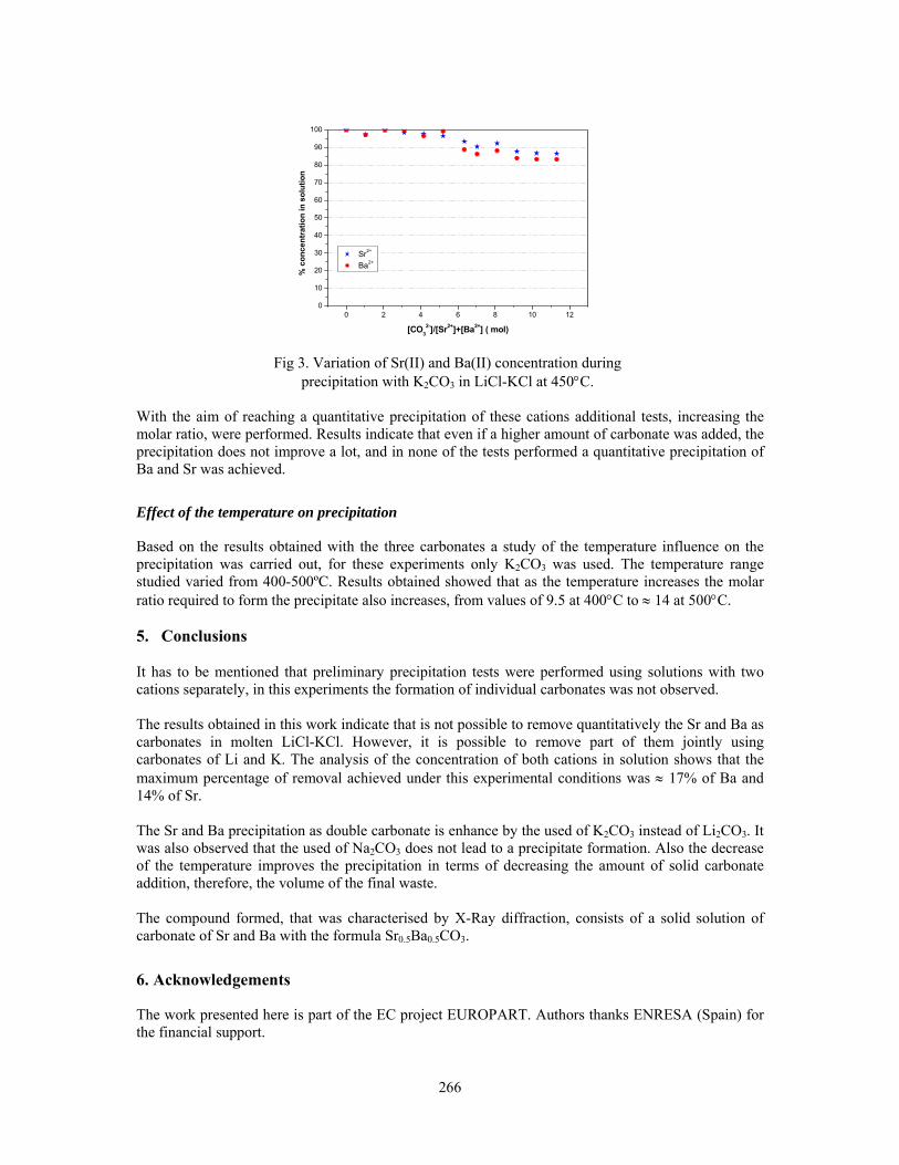
266
0 2 4 6 8 10 120
10
20
30
40
50
60
70
80
90
100
% c
once
ntra
tion
in s
olut
ion
[CO32-]/[Sr2+]+[Ba2+] ( mol)
Sr2+
Ba2+
Fig 3. Variation of Sr(II) and Ba(II) concentration during
precipitation with K2CO3 in LiCl-KCl at 450°C. With the aim of reaching a quantitative precipitation of these cations additional tests, increasing the molar ratio, were performed. Results indicate that even if a higher amount of carbonate was added, the precipitation does not improve a lot, and in none of the tests performed a quantitative precipitation of Ba and Sr was achieved.
Effect of the temperature on precipitation
Based on the results obtained with the three carbonates a study of the temperature influence on the precipitation was carried out, for these experiments only K2CO3 was used. The temperature range studied varied from 400-500ºC. Results obtained showed that as the temperature increases the molar ratio required to form the precipitate also increases, from values of 9.5 at 400°C to ≈ 14 at 500°C. 5. Conclusions It has to be mentioned that preliminary precipitation tests were performed using solutions with two cations separately, in this experiments the formation of individual carbonates was not observed. The results obtained in this work indicate that is not possible to remove quantitatively the Sr and Ba as carbonates in molten LiCl-KCl. However, it is possible to remove part of them jointly using carbonates of Li and K. The analysis of the concentration of both cations in solution shows that the maximum percentage of removal achieved under this experimental conditions was ≈ 17% of Ba and 14% of Sr. The Sr and Ba precipitation as double carbonate is enhance by the used of K2CO3 instead of Li2CO3. It was also observed that the used of Na2CO3 does not lead to a precipitate formation. Also the decrease of the temperature improves the precipitation in terms of decreasing the amount of solid carbonate addition, therefore, the volume of the final waste. The compound formed, that was characterised by X-Ray diffraction, consists of a solid solution of carbonate of Sr and Ba with the formula Sr0.5Ba0.5CO3.
6. Acknowledgements
The work presented here is part of the EC project EUROPART. Authors thanks ENRESA (Spain) for the financial support.

267
7. References [1] Accelerator-driven systems (ADS) and Fast Reactors (FR) in Advanced Nuclear Fuel Cycles. A
comparative study. NEA report 2002.
[2] Y. Sakamura, T. Inoue, et al. Proceedings of Global 1997. Yokohama, Japan, p. 1222.
[3] Y. Ikeda, M. Kumagal, et al. Proceedings of Global 1993, Seattle, Washington, USA, p. 184.
[4] C. Caravaca, G. Córdoba. CIEMAT Report DFN/RR-04/IF04, 2004.
[5] Deliverable No. 16 of the RYROREP project of the EC. Contract N0 FIKW-CT-2000-00049.
[6] R. Combes, F. Andrade, et al. Electrochim. Cta, 25, 1980, p. 371.
[7] Y. Mottot, Ph. Thesis, Université Pierre et Marie Currie, Paris IV. 1986.
[8] V.L. Cherginets, T.G. Deineka, et al. J. Electroanal. Chem, 531, 2002, p. 171.
[9] V. A. Volkovich, T.R. Griffiths, R.C. Thied, J. Nucl. Mat. 323, 2003, p. 49.
[10] V.A. Volkovich, T.R. Griffiths, R.C. Thied. Phys. Chem. Chem. Phys., 5, 2003, p. 3053.
[11] Matsumiya et al, J. Nucl Sci. and Technol., 34, 3, 1997, p. 310 and 35,11 1998, 836.
[12] Final report PYROREP project of the EC. Contract N0 FIKW-CT-2000-00049.
[13] Y. Hoshino, J.A. Plambeck,. Can. J. Chem., 48, 1970, p. 658.
[14] H.A. Laitinen., W. Ferguson, and R.A. Osteryoung, Preparation of pure fused lithium chloride-potassium chloride eutectic solvent. J. Electrochem. Soc., 1957. 104, p. 516.
[15] C. Caravaca, G. Córdoba, M.J. Tomás, A. G. Huebra, G. Piña. EUROPART- second periodic activity report –PAR Nº 4-Ciemat, December. 2004.
268
IR-100 RESEARCH REACTOR AND PROPOSALS FOR SPENT NUCLEAR FUEL MANAGEMENT
S.Yu. BULKIN, V.D. TIKHONOV, V.A. PARABIN Research and Development Institute of Power Engineering
POB 788, 107014, Moscow, Russia
S.B. SMIRNOV, V.N. PODTYNNYKH Sevastopol National Institute of Nuclear Energy and Industry
Kurchatov st., Sevastopol, Ukraine
ABSTRACT IR-100, a pool-type research reactor, is based in the city of Sevastopol, the Ukraine. The core is composed of 47 fuel assemblies (FA). The fuel assemblies use EK-10 fuel elements with a uranium dioxide meat in a magnesium matrix contained in an aluminum cladding. The external diameter of the aluminum cladding is 10 mm and the cladding thickness is 1.5 mm. There are no currently a reliable SNF storage facility and an agreed SNF handling program at IR-100. This report presents proposals and ways for addressing the SNF handling problem.
1. Introduction The IR-100 research reactor is a unique installation in the Ukraine as there are only two research reactors in the country. One reactor is in Kiev and the other is in Sevastopol. At present time, IR-100 is used to train personnel for the Ukraine’s nuclear power complex as part of the Sevastopol National Institute of Nuclear Energy and Industry (SNINEI). The reactor's first criticality was achieved on April 18, 1967 and the reactor was commissioned on October 18, 1967. The reactor designer is Research and Development Institute of Power Engineering (NIKIET), Moscow. Since its first criticality in 1967, the reactor has produced some 1 400 000 kWh of power. 2. IR-100 reactor and its nuclear fuel IR-100 is heterogeneous, light water moderated and cooled pool-type research reactor. Data and characteristics of IR-100 reactor are presented in Table 1.
Reactor tank∗ diameter 1800 mm Reactor tank height 4400 mm
Thermal power 200 kW Maximum fuel cladding temperature 100°C
Maximum core outlet temperature 55°C Reflector Two layer graphite with the total thickness 400 mm
Core Hexagonal prism with the height of 500 mm and the
circumscribed diameter of 460 mm. Total weight of U-235 in the core is 2.66 Kg
∗ Reactor tank is installed in a well within the biological shielding. Table 1. Data and characteristics of IR-100 reactor
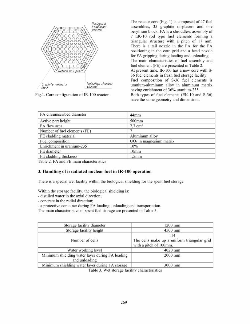
269
Fig.1. Core configuration of IR-100 reactor
The reactor core (Fig. 1) is composed of 47 fuel assemblies, 35 graphite displacers and one beryllium block. FA is a shroudless assembly of 7 EK-10 rod type fuel elements forming a triangular structure with a pitch of 17 mm. There is a tail nozzle in the FA for the FA positioning in the core grid and a head nozzle for FA gripping during loading and unloading. The main characteristics of fuel assembly and fuel element (FE) are presented in Table 2. At present time, IR-100 has a new core with S-36 fuel elements in fresh fuel storage facility. Fuel composition of S-36 fuel elements is uranium-aluminum alloy in aluminum matrix having enrichment of 36% uranium-235. Both types of fuel elements (EK-10 and S-36) have the same geometry and dimensions.
FA circumscribed diameter 44mm Active part height 500mm FA flow area 7,7 cm2
Number of fuel elements (FE) 7 FE cladding material Aluminum alloy Fuel composition UO2 in magnesium matrix Enrichment in uranium-235 10% FE diameter 10mm FE cladding thickness 1,5mm
Table 2. FA and FE main characteristics 3. Handling of irradiated nuclear fuel in IR-100 operation There is a special wet facility within the biological shielding for the spent fuel storage. Within the storage facility, the biological shielding is: - distilled water in the axial direction; - concrete in the radial direction; - a protective container during FA loading, unloading and transportation. The main characteristics of spent fuel storage are presented in Table 3.
Table 3. Wet storage facility characteristics
Storage facility diameter 1200 mm Storage facility height 4500 mm
Number of cells 114
The cells make up a uniform triangular grid with a pitch of 100mm.
Water working level 4020 mm Minimum shielding water layer during FA loading
and unloading 2000 mm
Minimum shielding water layer during FA storage 3000 mm

270
Fig. 2. Scheme of the FAs loading and unloading
The technology of FAs loading and unloading incorporates the following stages (Fig. 2): The container (pos. 1) with a canister (pos. 2) is installed on the upper rotary plate (pos. 3). The canister is lowered down to the reactor upper edge level (pos. 4). A manual clamp grip (pos. 5) is introduced to inside of the reactor through a hole in the upper rotary plate. The clamp grip transports the selected FA (pos. 6) and loads it into the canister. The canister with the FA is further drawn into the protective container. The latter is transported to the SFA storage facility. The FA is loaded into a storage cell using the same flowchart. The storage facility body is a cylindrical welded vessel of AD1 aluminum alloy with the internal diameter of 1200 mm and the height of 4270 mm. The grid for the FAs arrangement is made of 2 plates interconnected through tubes welded into the plate holes. To load an FA into the storage facility, the FA tail nozzle is fit in the grid tube so that to keep the FA spacing in storage and avoid the FA displacement. According to calculations, К∞ does not exceed 0.423 ± 0.007 for an infinite number of the IR-100 FAs kept in water with a spacing of 100 mm over the triangular grid. It should be noted that at present time there is not a single spent fuel assembly (SFA) loaded into the storage facility. The explanation is that the fuel burnup reached during operation is much below the permissible value.
4. Core leak-tightness monitoring
The radiation situation in working rooms during the reactor operation depends on the ionizing radiation penetrating through the biological shielding, the primary coolant, the air pumped by the special ventilation system and activated structural materials. The coolant activity is caused by: - the coolant and its impurities activation under neutron effect; - activation of structural materials corrosion products. The reactor core state is analyzed and predicted based on the magnitude and nature of the dry residue
1
2
3
5
4 6

271
activity change, the total of the iodine isotopes in the coolant and the activity of radioactive gases in the release through special ventilation. The coolant samples are taken during the reactor rated power operation (after not less than 4 hours). The state of the reactor FA integrity is assessed based on the criteria presented in Table 4.
Major indices Additional indices
Core state Specific activity of the coolant in terms of dry
residue, Ci/l
Specific activity of iodine in the coolant, Ci/l
Volume activity of the air in the release system,
Ci/l Normal ≤ 1.5⋅10-7 ≤ 3⋅10-8 ≤ 2⋅10-7
Acceptable 1.5⋅10-7 – 1.5⋅10-4 3⋅10-8 – 1⋅10-5 2⋅10-7 – 5⋅10-7 Inadmissible >1.5⋅10-4 >1⋅10-5 >5⋅10-7
Table 4. Analysis of the FA leak-tightness state (main parameters)
An additional criterion of the fuel cladding failure is an increase in the activity of gaseous fission products (largely Хе135) in the coolant by not less than twice as compared to the previously recorded value with the same activity of the total iodine isotopes. Design of IR-100 fuel elements proved to be very reliable and as a result not a single non-leak-tight FA has been found in the reactor core during 38 years of IR-100 operation. 5. Proposals developed to secure a safe and reliable SNF storage As has been noted above, none of the SFAs has been loaded into the storage facility from the reactor. At the same time, it should be noted that the SFAs were loaded in the reactor about 40 years ago and in the case of SFAs transferring to the existing wet storage it would be a prolongation of exposed time of water – cladding direct contact. As a consequence the possibility of fuel cladding failure because of corrosion processes should be taken in consideration. In order to reduce the possibility of fuel elements failure, the nuclear fuel after being unloaded from the reactor should be transferred for safe interim “dry” storage enabling their following transfer for reprocessing. It is reasonable that the interim “dry” storage of SNF and its preparation for being transferred for reprocessing should be arranged for on the IR-100 complex site. As such, the SNF reprocessing may be successfully organized at NPO “MAYAK”, Russia. The SNF should be brought to a safe condition to ensure nuclear and radiation safety during storage. The criteria of safe SNF storage are as follows: - the correct selection of the SFA arrangement geometry in the storage facility; - the availability of a biological shielding for personnel; - the availability of a system of organizational and technical measures to ensure the SNF state monitoring; - a reliable system of physical safety at the SNF handling installation. Two proposals have been considered to secure a safe and reliable SNF storage: storage in dry stationary storage facility and storage in dual-purpose containers. 5.1. SNF intermediate storage in a stationary facility The storage facility is a metal tank installed on a concrete platform or in a well. The loading into the storage facility is performed through the upper plate into the cells for the SNF arrangement in the tank. The cell number corresponds to the number of the IR-100 SFAs. SFAs should be placed in special canisters to avoid the SNF contacts with water used as biological shielding. The canisters are installed in the storage cells directly prior to the SFAs unloading from the reactor for storage. The SFAs are loaded into canisters using a shipping cask based on a technology tried out by the reactor personnel. The SNF condition is monitored using special systems currently used as part of the IR-100 laboratory. The state of the SNF in long-term storage may be examined during the storage facility operation.

272
If it is required to remove the SNF for reprocessing, the special canisters with FA are sealed, loaded into special shipping casks and onto a vehicle. 5.2. SNF intermediate storage in dual-purpose containers Dual-purpose containers (protective container) are used for interim storage and transportation of SNF to reprocessing points. Described hereinafter is a potential design of a protective container (Fig. 3) with the SFA loading from below. This simplifies considerably the SFA handling technology. A protective container is a hollow thick-wall cylinder (pos. 1). A special crosspiece is used to transfer the container by a hoist. The container body has two pivots (pos. 2) in its upper portion to be gripped with the crosspiece. The clamp grip for the canisters with SFA is led to the inside of the container from the upper end. The container lower portion has a rotary slide (pos. 3) used to seal the internal space after the SFA canister loading. A handle with two fixed positions of “OPEN” and “CLOSED” is used to operate the slide. The internal space is sealed from the above using a process lid (pos. 4). Pressure bolts are used to seal the process lid. A receiving yard with special outfit is used for interim storage of containers with SFAs. The yard has access road and a hoist for the loading of containers onto vehicles.
6. Conclusion In the course of IR – 100 reactor operation, 47 FAs with road-type FEs in aluminum cladding were used. During 38 years of reactor operation, not a single non-leak-tight FA has been found in the reactor core. In accordance with the design, the SFAs should be placed into a wet storage facility, but at present time there is not a single SFA loaded into existing storage facility. The SFAs transferring to the wet storage (the prolongation of exposed time of water – cladding contact) may cause the corrosion failure of SFAs. Two options have been considered to raise the reliability of storage: - storage in dry stationary storage facility - storage in dual – purpose containers. The fist option is more expensive, and due to a low number of SFAs, the preferable option is storage in dual – purpose containers. In both options the intermediate storage of SFAs is the fist step for further repossessing.
1 1 1
2
3
4
Fig.3. Scheme of the protective container

Conference Secretariat: European Nuclear Society
Rue de la Loi 57 1040 Brussels, Belgium
Tel. +32 2 505 30 50 - Fax +32 2 502 39 02 E-mail [email protected]
http://www.euronuclear.org