rpt of ip sur w cobble l grid - ontario · strong ancq;giies, however, they are no doubt outlining...
TRANSCRIPT
52F13SEM28 63.2876 BRIDGES 010
KaPOKT
II.'JL;CJ:D R'LAhi.J
COB13L-. L^:lA GhID
CCBBL^
May 1970 :-. .11. -ays,
SUMMARY
During the early part of April 1970, an induced
polarization surrey was carried out by the Falconbridge
Nickel Mines Limited, Noranda Quebec based crew. The
survey was carried out over a grid of lines located on
the west end of Cobble Lake.
The objective of the survey was to determine
whether any significant amount of mineralization occurred
along the interpreted ultramafic intrusions in the area*
The survey was carried out employing a gradient array
and due to the warm weather, the ice conditions did not
allow detailing of the conductive zones with other arrays.
In general, the survey has outlined several anoma
lous zones ranging mostly from moderate to weak responses*
There are, however, two zones which appear to be of inte
rest, Zone 1 which lies along what is possibly a north
contact of the ultramafic and ^ne 3 which lies along the
south contact. Zone 2 appears to be associated directly
with the ultramafic zcne as outlined by a zone of slightly
higher than oackground resistivities.
The resistivity survey has tended to reflect the
probable increased amount of silt through the center
part of the Lake and a zone of higher than background
resistivities appear to correlate well with magnetic
highs outlined by a previous survey. Lone *f, located
on the northwest side of the interpreted ultramafic

Page -2-
zone is probably also reflecting increased mineraliza
tion in that area.
Although the anomaly outlines are relatively vide,
the actual zones of increased mineralization are probably
narrow lying within the outlined anomalies.
Page -3-
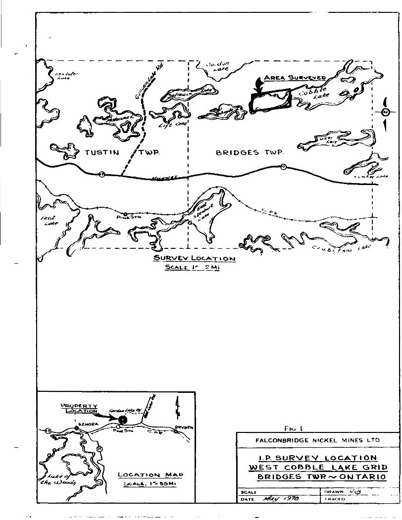
LOCATICN AND ACCESS
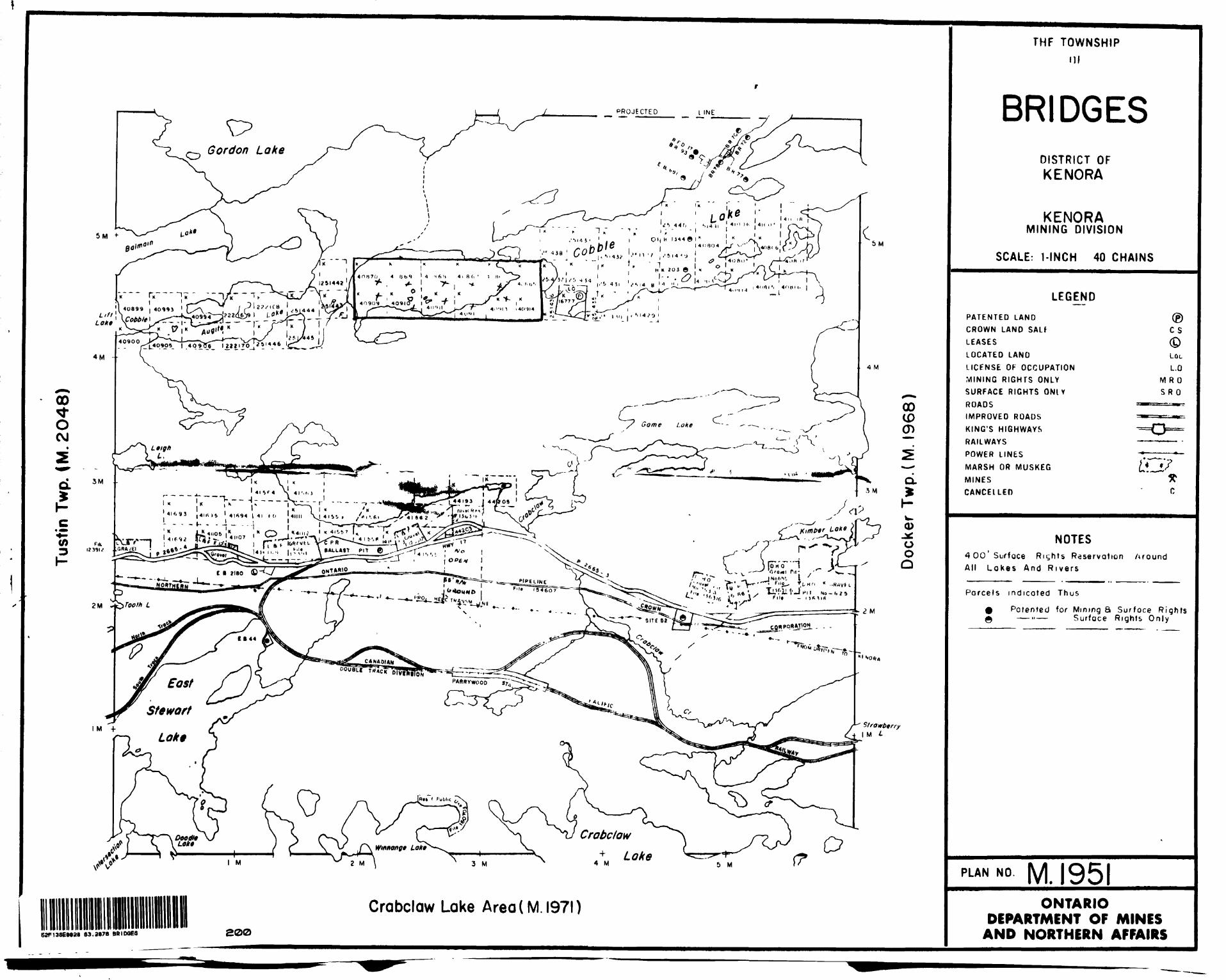
The grid of lines covered is on the vast end of
Cobble Lake which is located in the north central part
of Bridges Township in the Kenora Mining Division of
Northwestern Ontario. The location of the survey area
is outlined on the location map presented as Figure 1 .
The claims covered by the survey are» NO.KUO866
to K*K>370 Inclusive and No. KW0909 to K**0913 inclusive.
The property is accessible from the Town of
Vermilion Bay approximately fifteen miles to the east
by travelling west along Highway 17 to the Gordon Lake
road and then two miles north along this lumber company
road to where it intersects the chain of lakes shown on
the map as Medicine Lake, Lift Lake, Aggot Lake and
Cobble Lake. The area surveyed oay be reached from the
road by travelling across Lift Lake and Aggot Lake to
the vest end of Cobble Lake, a distance of approximately
four miles. The property may also be reached by travell
ing cross country directly north from Highway 17 at a
point approximately four miles east of the Gordon Lake
road turn off. Although this distance is only two and
one half miles, it is somewhat more difficult to reach
the property as there is no convenient road or trail and
it therefore requires making a trail through the bush.

Page
PfrCPSRTY PREPARATION
Prior to the carrying out of the survey, a previously
cut grid of linesjised for past surveysjra3_ rejjQOstruetejL
in the area to be covered and the lines were projected
across the lake. The base line 0 + 00 which traverses
across the north side of the lake was used as the main
control line. Picket lines were turned off 90 to this
line at intervals of four hundred feet beginning at the
east end of the lake with line 20OW and increasing numeri
cally to the west to line 26*fW which is located at the
west end of the lake. The picket lines were chained off
at one hundred foot intervals increasing numerically north
and south from the base line 0 * 00.
The layout of the grid was carried out by a crew
employed by the Falconbridge Nickel Mines Limited, Thunder
Bay based exploration staff.
THaOF.Y ~ND KaTHOl) OF SURVSY
Induced Polarization Survey
A Huntec 7»5 K.V.'. I.F. unit whi,ch is a pulse system
was employed. The field procedure using l.F. is rather ver
satile and the method of surveying is usually adapted to
comply with a geological and surface conditions on the pro
perty. Basically, a set of current probes are set out in
accordance with the particular array being used (these
arrays or configurations are the same as many of those

Page -5-
ased In doing resistivity surveys, examples of which can
be found in several geophysical text books). Wires are
then spread out from the transmitter (located conveniently
near the area) and are connected to the current probes
referred to as Cl and C2. DC current is then passed through
the ground alternating at intervals of, (example, l£ seconds
on positive north, £ second off, l£ seconds on negative
north). Measurements are then taken along lines by means
of two potential probes referred to as PI and P2 which
are placed according to the array used and connected to a
receiver unit which synchronize with the transmitted sig
nal. .rimary voltage (Vp) are measured when the current is
in the l£ seconds on period. The secondary voltage (Vs) is
then measured when the current is in the £ second off pe
riod.
A simplified explanation of induced polarization
theory is that if a current is passed through a resistant
material such as rock, any metallic particles will charge
up (polarize) and if the current is turned off, a voltage
will remain i.i those particles and discharge gradually for
a period of time. The reading taken at this time is called
the sec ndary voltage. The magnitude of this voltage is
proportionate to the amount of conductive material present,
Chargeability is calculated from the following
formula*
Vs *K)0 = chargeability in milliseconds.

Page -6-
Where as aentioned, Vs i s the secondary voltage, Vp is the
primary voltage and the UOO figure is the period in milli
seconds within the i second off time that the secondary
voltage is measured.
Kesistivity is calculated using formulas applied
according to the array used and includes the Vp reading
in all cases.
A discussion of 1.1 . surveys may be found in se
veral geophysical text books some of which are: "Mining
Geophysics" by D.b.Parasnis, "Overvoltage Research and
Geophysical Application" by J.h,kaite, in a paper by
li.O.oeigel, C.I.i'i. Transactions, Volume 65, 1962.
Procedure
Gradient Array
In carrying out the gradient array survey (used
in this survey) the following procedure was carried outi
two current probes Cl and C2 respectively are placed at
opposite ends of the area to be surveyed, connected to
the transmitter unit by plastic covered copper wire.
The separation between the current probes is usually
twice the distance of the area to be surveyed. The cen
ter point located at the center of the survey area. The
current wire is usually laid along one of the picket lines
in the center of the area. If the area of the survey to
be measured is two thousand feet then the current probe
separation will be four thousand and this will allow
• e t
Page -7-
measurements to be taken on lines extended up to one thou
sand feet perpendicular to either side of the current line.
Field measurements are then taken along each picket line
using two potential probes spaced at usually one or two
hundred feet apart. As the current is passed through the
current probes Cl, C2, Vp readings are measured across
the potential probes PI, P2 when the current is in the on
node, /s or secondary voltage readings are measured when
tha current is in the off mode* As mentioned the charge-
ability (i-I/0 is calculated from: Vs x *+QQ*P
The resistivity is calculated with the following fomulai
~* * * P H ~ g « f *•• ft.
where f - resistivity^* £ the length of the current spread
Cl to C2, A= the distance between the potential probes
(Fl, P2), Vp the primary voltage reading, 1» tha trans
mitted current in amps., K the spacing factor which cor
rects for the variation in current flow due to the confi
guration.
To expedite this survey, a five man crew was re
quired, employed as follows* (Fl) receiver operator, (P2)
lead potential probe man, transmitter operator and two
men employed laying and retrieving current wire,
The layout is shown in figure d. of this report.

Page -3-
GEOPHYSICAL INTERPRETATION
The results of the gradient array survey carried
out over this grid are presented as four maps shown as
Plate 1-Anocialy Plan, Plate 2-Apparent Resistivity, Pla
te 3-:,pparent Chargeability and Plate V-A plan of metal
factors calculated from the Chargeability and resistivity.
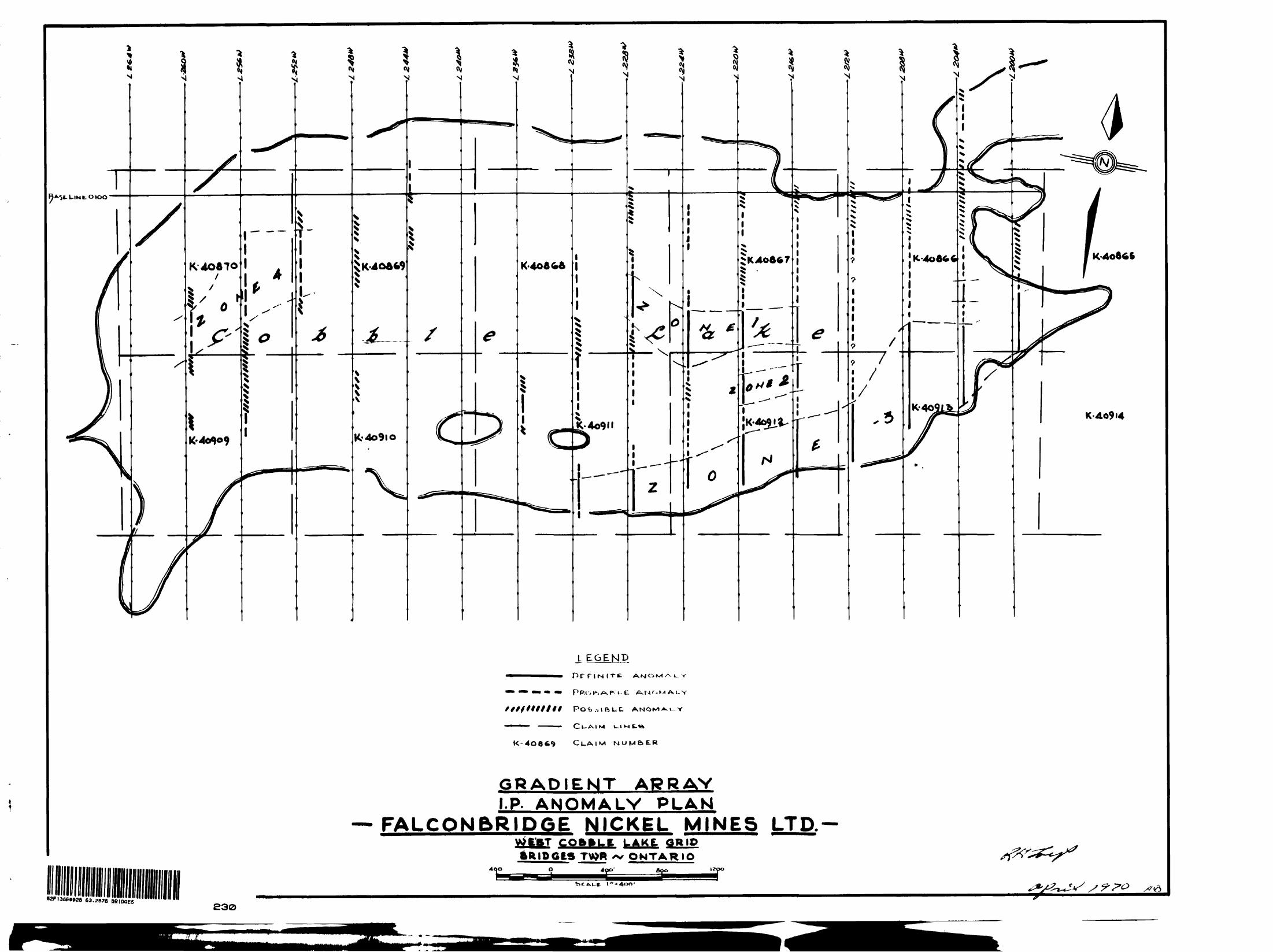
The anomaly plan outlines the anomalous zones in-
dica ed by the survey. Although there are reveral anoma
lous zones outlined, most range from moderate to weak
conductors outlined as probable and possible anomalies.
There are, however, three zones outlined as definite ano
malies which are considered good conductive rones and are
indicated as ^one 1, 2 and 3»
^one 1, located on lines 2l6w to 228W at approx
imately 10003, is outlined by a series of metal factor
values in the order of one hundred to one hundred and
seventy five. Altnough this zone is indicated as a defi
nite anomaly, the netal factor values are on the low end
of the scale for this type of conductor indication. When
looking at t'.ie chargeabilities and resistivities, it can
be seen that the metal factors are mainly due to signifi
cantly low resistivities and that the chargeabilities are
only slightly above background. Ihis zone is located within
a rather broad anomalous area and could be projected both
east and west to tie in with zones shown as probable ano
malies which lie directly along strike.

Page -9-
Zone 2 is a more narrow and shorter anomalous zone
lying immediately south of No.l and is outlined by similar
metal factor values, once again, this zone appears to be
outlined by mostly lower resistivities with only moderate
change in the chargeability pattern.
iione 3 is located along the south side of the lake
from line 200W to line 232V.1 , thir zone is outlined by me
tal factors of similar order to those found on Zones 1 and
2. Cn looking over the resistivity and chargeability, it
can be seen that the resistivity in this area is slightly
higher than on the other zones, however, the chargeability
is considerably stronger. This may make this zone more sig
nificant than the others.
A fourth zone is outlined on the west side of the
lake, "his is a relatively weak response outlined by metal
factor values slightly less than one hundred, however, some
importance snould be placed on it as it is outlined by a
series of chargeabilities which are well above background,
.."one of the zonos outlined can be considered as
strong ancQ;giies, however, they are no doubt outlining
increared mineralization.
-he resistivity plan outlines a series of low re
sistivities lying generally through the middle of the lake
which may be partly due to an increased amount of silt de
posited there. The lower resistivities could also, however,
be outlining increased amounts of lower resistivity material
Page -10-
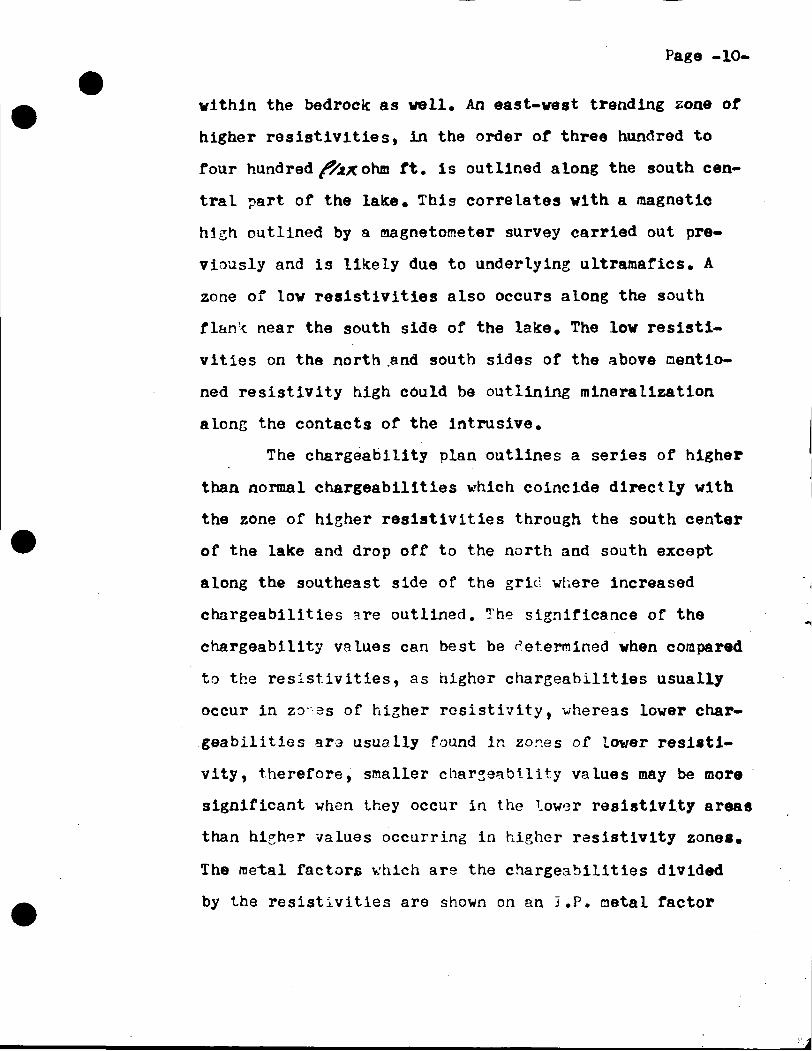
vithin the bedrock: as well. An east-vest trending zone of
higher resistivities, in the order of three hundred to
four hundred f/jtx ohm ft. is outlined along the south cen
tral part of the lake. This correlates with a magnetic
high outlined by a magnetometer survey carried out pre
viously and is likely due to underlying ultramafics. A
zone of low resistivities also occurs along the south
flan'< near the south side of the lake. The low resisti
vities on the north .and south sides of the above mentio
ned resistivity high could be outlining mineralization
along the contacts of the intrusive.
The chargeability plan outlines a series of higher
than normal chargeabillties which coincide directly with
the zone of higher resistivities through the south center
of the lake and drop off to the north and south except
along the southeast side of the grid where increased
chargeabilities are outlined. The significance of the
chargeability values can best be determined when compared
to the resistivities, as higher chargeabilities usually
occur in zo as of higher resistivity, vhereas lower char
geabilities ara usually found in zor.es of lower resisti
vity, therefore, smaller charseability values may be more
significant when they occur in the lower resistivity areas
than higher values occurring in higher resistivity zones.
The metal factors which are the chargeabilities divided
by the resistivities are shown on an I.P. netal factor

Page -11-
plan and outline the zones shown on the anomaly plan*
In summary, it would appear as though the modera
tely high resistivity lying through the south center part
of the lake is outlining the ultramafic intrusive and
that the lover resistivities which in part reflect the
higher metal factors along both the north and south
flanks of this zone could be indicating increased amounts
of aineralization along the north and south contacts.
Respectfully submitted,
^-.!i. lays.

Page -12-
Induced Polarization Survey
Huntec, pulse type 7.5
Time Cycle:
headings Recorded:
Receiver Range:
Sensitivity:
Measurements recorded:
Metal Factor shown asi
Configuration Used:
i. MK1, I.P. unit
l£ sec.on, i sec.off B.C. current (alternating the polarity with each "on" period)
In volts
5 scale positions 3 x KT2 ,10~2 to 10-5
.0001 volts per scale div on most sensitive scale increasing proportio nately with each scale range
Apparent resistivity recorded as f/zx ohm ft.Chargeability recorded in milli seconds.
Chargeability/resistivity x 10OO
Gradient array
Page -13-
11
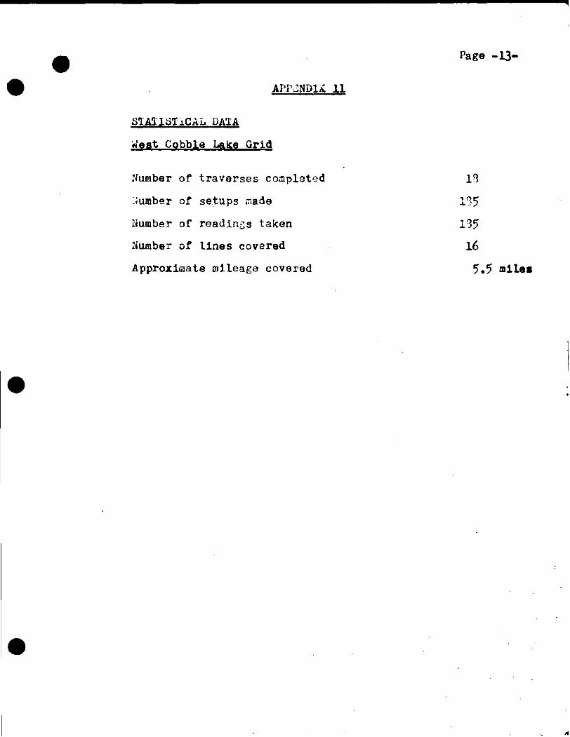
STATISTICAL DATA
West Cobble Lake Grid
Number of traverses coapleted 13
dumber of setups made 135
Number of readings taken 135
Number of lines covered 16
Approximate mileage covered 5.5 miles
BRIDGES TVs>P
SCALE i* 2 Mi
flBVPEH
FALCONBRIDGE NICKEL MINES LTD
I.P. SURN/EV LOCATION
WEST COBBLE LAKE GRIP
BRIDGES T\»T?^ ONTARIO
SCALE
'97<O

'VJ
» v/yi i '•" i
' T
'^ ;___ ___I
> u
f-I'~ o
I'
I
t
———— ' 1
*6

PROJECTS SECTION
ONumo
DEPARTMENT OF MINES AN
TECHNICAL ASSESSME™ i63.2676 BRIDGES
oncui 10900
Recorder Holder
Township or Area
Type of Survey and number of Assessment Days Credits per claim
GEOPHYSICAL Airbornedl Ground!
Magnetometer ............ ........................days
Electromagnetic ................................ .days
Radiometric ..................................... ..days
SECTION 84 (14).
Special Provision |_
.days
Man days
NOTICE OF INTENT TO BE ISSUED
| | Credits have been reduced because of partial coverage of claims.
I | Credits have been reduced because of corrections to work dates and figures of applicant.
| | NO CREDITS have been allowed for the following mining claims as they were not sufficiently covered by the survey:
/^Mining Claims/A
IX?
\J
The Mining Recorder may reduce the above credits if necessary in order that the total number of approved astettment days recorded on each claim does not exceed the maximum allowed as follows: Geophysical - 80; Geological - 4O; Geochemical - 40;
oOsJ
a
c "S>
PROJECTED I INE
4.,.,,4 I«"«'^ L 4"»'" | \
- - ,) _ _ _ _ _^. _ _ _- ^^- i ""S^BB^- - br— " -J " / " ^^""*'-*jr ̂ fu k .l««;4iit,, /^'.si^-^^TTsT " 'k|ibi " ^^-»-—T^srCS " _.**^._^^:=?5>
iii MJ '41111"»•—T*5—^^~r* » «*\-^.«-f. F^A" r^-j-i 1 -''"«,.'.. ^ ;^R ^t-^^_——!H_1 ^\^>-^-
\riTrtT "1 ^ U — -r~ ' V.ra,., r,i -^ S^ ̂- N -"
00 CD
Q.^ I-W.0)
u oQ
Strowbtrry!M L
3 M 5 M(/* D
Crabclaw Lake Area (M. 1971)
THF TOWNSHIP Ml
BRIDGESDISTRICT OFKENORA
KENORAMINING DIVISION
SCALE: 1-INCH 40 CHAINS
LEGEND
6Sn38E»»2S 63.8876 BO I DOES 200
PATENTED LANDCROWN LAND SALf
LEASESLOCATED LANDLICENSE OF OCCUPATIONMINING RIGHTS ONLYSURFACE RIGHTS ONIV
ROADSIMPROVED ROADSKING'S HIGHWAYSRAILWAYSPOWER LINES
MARSH OR MUSKEGMINESCANCELLED
NOTES400' Surface Rights Reservation Around All Lakes And Rivers
Parcels indicated Thus
Patented for Mining & S urface Rights — » — Surface Rights Only
PLAN NO . 1951
ONTARIODEPARTMENT OF MINES
AND NORTHERN AFFAIRS

10-0
LEGCND
I-P. OHARGtABlLlTV VALUES IN M
CHARGE.ABIUITY CONTOURS
C.OKJ
C.ONTOUR . I- I Q-Z-^-^~7^-\
GRADIENT ARRAY i-P. CHARQEABILITY PLAN
FALCONBRIDGE NICKEL MINES LTD.-WEST CObftLE LAKE. GRID BRIDGE TWP.~ ONTARIO
52F13SEM28 B3.287B BBIDQE6 £10

LEGEND17ft APPARENT RESISTIVITY
RESISTIVITY CONTOURS
CONTOUR INTERVALS, I* |.5-e-S-5-7.5-lO
BRIDGES sso
GRADIENT ARRAY 1-P. RESISTIVITY PLAN
FALCONBRIDGE NICKEL MIN ES LTD.-WEST COftfrLE LAKE. GRIP BRIDGES TU>P ~ ONTARIO
LEGEND
. u t X^UOM A.UV
Po -b .-> I R L. D ANOMA.U-V
K-4O669
GRADIENT APRAY I. P. ANOMALY PLAN
FALCON&RIDGE NICKEL MINESftMDCtS T\»»R /v ONTARIO
LTD.-
4QO
6SF.36E.02a 63.2876 BRIDQES
£30
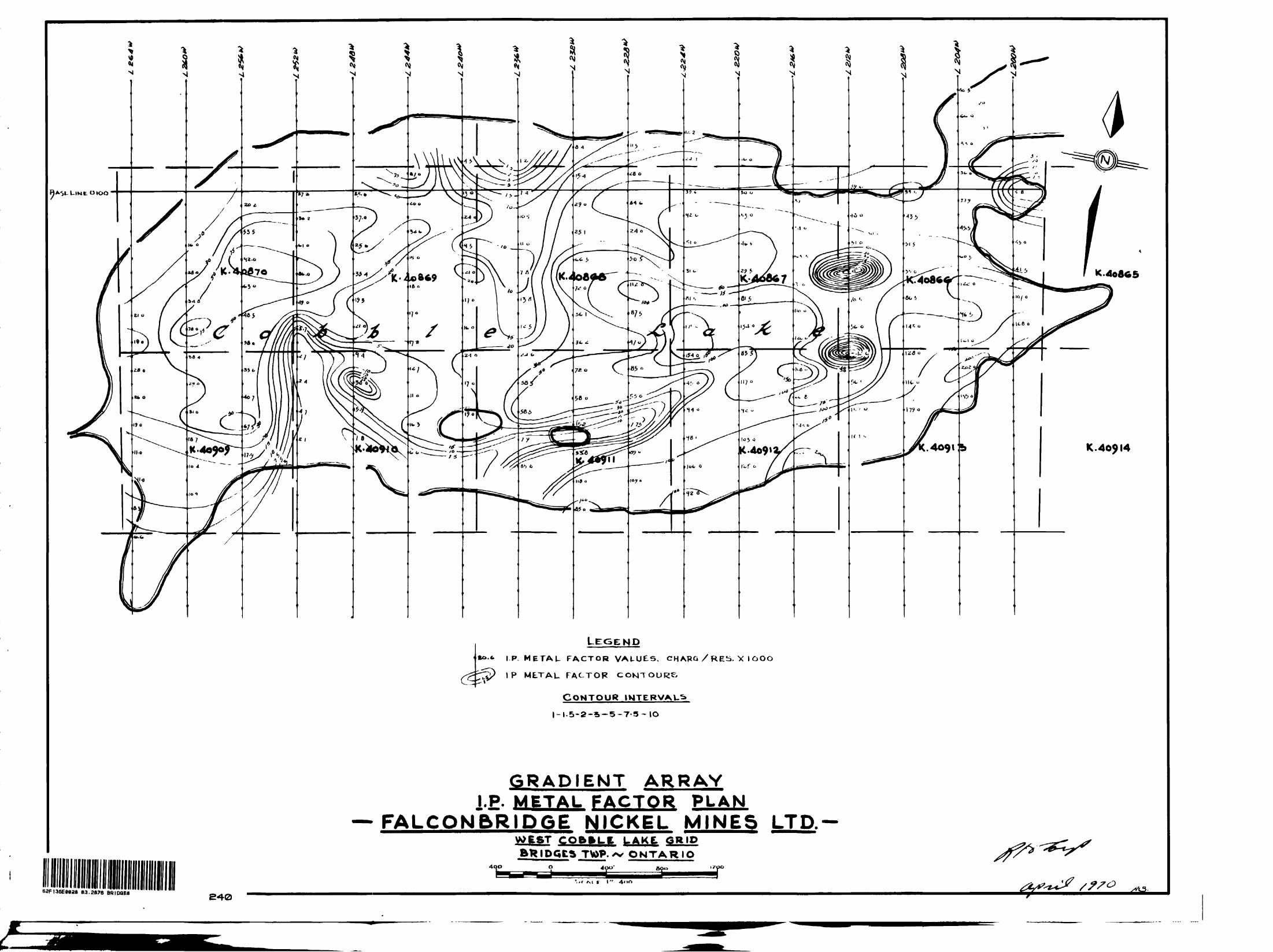
LEGEND*»•«• I.P. METAU FACTOR VALUES. CHARG /RES. x 1000
IP MLTAU FACTOR CONTOURS
CONTOURI-I.5-2-S-5-7-5-IO
GRADIENT ARRAY I.P. METAL FACTOR PLAN
FALCON&RID6E NICKEL MINES LTD.-COftELt LAKE. GRID
TVi>P. ^ ONTARIO
40^14
62FI3SE«0aa 83.2876 BRIDQE8