cobble hill landfill final closure plan report
TRANSCRIPT

REPARED FOR: Cobble Hill Holdings Ltd.PREPARED BY: SPERLING HANSEN ASSOCIATES
May 31st, 2017PRJ 17039
• Landfill Engineering• Solid Waste Planning• Environmental Monitoring• Landfill Fire Control
Cobble Hill Landfill Final Closure Plan
REPORT

CONFIDENTIALITY AND © COPYRIGHT
This document is for the sole use of the addressee and Sperling Hansen Associates Inc. The document contains proprietary and confidential information that shall not be reproduced in any manner or disclosed to or discussed with any other parties without the express written permission of Sperling Hansen Associates Inc. Information in the document is to be considered the intellectual property of Sperling Hansen Associates Inc. in accordance with Canadian copyright law.
This report was prepared by Sperling Hansen Associates Inc. for the account of Cobble Hill Holdings Ltd. The material in it reflects the best judgment of Sperling Hansen Associates Inc. in the light of the information available to it, at the time of preparation. Any use which a third party makes of this report, or any reliance on or decisions to be made based on it, are the responsibility of such third parties. Sperling Hansen Associates Inc. accepts no responsibility for damages, if any, suffered by third party as a result of decisions made or actions based on this report.

Landfill Engineering Solid Waste Planning Environmental Monitoring
Landfill Fire Risk Control
Proudly Sperling Hansen Associates Inc. · #8 – 1225 East Keith Road Supporting: North Vancouver · British Columbia · V7J 1J3 Phone (604) 986 7723 · Fax (604) 986 7734 www.sperlinghansen.com
May 31st , 2017 SHA PRJ 17039 Cobble Hill Holdings Ltd. 460 Stebbings Road Shawnigan Lake BC V0R 2W3 Attn: Mr. Martin Block CC: Ministry of Environment Office of the Minister Parliament Buildings Victoria BC V8V 1X4 Re: Cobble Hill Landfill Final Closure Plan Sperling Hansen Associates (SHA) is pleased to submit a FINAL copy of the Cobble Hill Landfill Final Closure Plan for your review. The Final Closure Plan developed by Sperling Hansen Associates is intended to meet the guidelines of the second edition of the British Columbia Landfill Criteria for Municipal Solid Waste (LCMSW), as well as address the Spill Prevention Order MO 1701. Sperling Hansen Associates is confident the engineering design for the closure plan will meet the needs of the landfill, ensure long term environmental protection, and address concerns brought forward by the Ministry of Environment in recent correspondence. In addition to requirements for the Closure Plan outlined in the second edition LCMSW, the closure plan includes the following assessments as per MoE correspondence:
- Assessment of the adequacy of the existing facility,
- Landfill Stability assessment and Hydrologic modelling that demonstrates the final cover and ditching will be stable and adequate for worst case conditions including 1 in 200-year storm event, plus snowmelt and multi-day precipitation events,
- Leachate collection and storage works assessment – ability to prevent an escape or spill of leachate into the environment,
- Leachate collection and storage plan– including hydrologic modelling that demonstrates the infrastructure is adequate for the worst-case conditions including 1 in 200-year storm events plus snowmelt plus precipitation,
- Leachate removal and transport plan,
- A plan for the management of contaminated soil stored in the Soil Management Area,
- Post closure inspection, operation and maintenance and environmental monitoring program,
- Implementation schedule for commencement and completion of closure activities.
SPERLING HANSEN ASSOCIATES
Cobble Hill Holdings
February 18th, 2017
Page 2SPERLING HANSEN ASSOCIATES
SHA has addressed the above mentioned comments and has included a detailed assessment of the Landfill Design, which can be found in Chapter 3 of the Final Closure Plan. The results of our as-built and data review do not indicate any significant technical issues with the engineering of the Cobble Hill Landfill. Cost estimates are provided for upgrading the final cover system of the Permanent Encapsulation Area and for long term post closure care and monitoring. SHA notes that the landfill was originally permitted and operated under the 1993 Landfill Criteria so it is not clear to us whether extending the post closure care requirement to 50 years is appropriate as the landfill stopped receiving waste before the new Criteria came into effect. Therefore, we have calculated the net present values for both the 25 year and the 50 year post closure periods so that others knowledgeable in such legal matters can ultimately establish the correct post closure security amount. After Submission and upon Ministry of Environment review of the Final Closure Plan, SHA suggests all parties arrange a meeting to review any questions or concerns the Ministry has regarding closure of the Cobble Hill Landfill site. We look forward to working on the next stage of this project with you. Please do not hesitate to call with any questions or concerns. Yours truly, SPERLING HANSEN ASSOCIATES Dr. Tony Sperling, P.Eng. President
May 31st, 2017

Cobble Hill Holdings Ltd. Cobble Hill Landfill i SPERLING
Final Closure Plan HANSEN
PRJ17039 FINAL REPORT ASSOCIATES
TABLE OF CONTENTS
1. INTRODUCTION
1.1 Background ................................................................................................................................ 1-1
1.2 Purpose and Scope ..................................................................................................................... 1-4
1.2.1 Project Startup and Field Work ........................................................................................... 1-4
1.2.2 Closure Plan ........................................................................................................................... 1-4
1.2.3 Reporting ................................................................................................................................ 1-4
2. SITE DESCRIPTION AND HISTORY
2.1 Physical Setting .......................................................................................................................... 2-1
2.2 Site History ................................................................................................................................. 2-1
2.2.1 Site Location ....................................................................................................................... 2-2
2.2.2 Legal .................................................................................................................................... 2-3
2.2.3 Permit .................................................................................................................................. 2-3
2.2.4 Geology and Hydrogeology ............................................................................................... 2-4
2.2.5 Climate ................................................................................................................................ 2-4
3. SOIL RELOCATION AND ENCAPSULATION
3.1 Contaminated Soil Relocation and Encapsulation Plan ......................................................... 3-1
3.2 Relocation of Soil from the Soil Management Area .............................................................. 3-2
3.3 Contact Water Management ..................................................................................................... 3-3

Cobble Hill Holdings Ltd. Cobble Hill Landfill ii SPERLING
Final Closure Plan HANSEN
PRJ17039 FINAL REPORT ASSOCIATES
3.4 Landfill Design Assessment ....................................................................................................... 3-3
4. LANDFILL CLOSURE DESIGN
4.1 Introduction ............................................................................................................................ 4-1
4.2 Final Cover Objectives .......................................................................................................... 4-2
4.3 Regulatory Requirements ..................................................................................................... 4-2
4.4 Earthworks and Environmental Controls ........................................................................... 4-3
4.5 Elements of the Final Cover Design on Landfill Crest ....................................................... 4-4
4.6 Elements of the Final Cover Design on Landfill Sideslopes .............................................. 4-6
4.7 Design Contingency ............................................................................................................... 4-7
4.8 Closure Construction Scheduling ......................................................................................... 4-8
5. LEACHATE MANAGEMENT
5.1 Introduction ................................................................................................................................ 5-1
5.2 Leachate Management Strategy ............................................................................................... 5-1
5.3 Leachate Generation .................................................................................................................. 5-2
5.4 Leachate Quality ........................................................................................................................ 5-3
5.5 Leachate Collection and Management ..................................................................................... 5-3
5.6 Leachate Monitoring ................................................................................................................. 5-5
5.7 Leachate Transportation Off Site............................................................................................. 5-5
5.8 Clean Run-off Treatment Strategy ........................................................................................... 5-5

Cobble Hill Holdings Ltd. Cobble Hill Landfill iii SPERLING
Final Closure Plan HANSEN
PRJ17039 FINAL REPORT ASSOCIATES
6. SURFACE WATER MANAGEMENT
6.1 Drainage Plan for the Cobble Hill Holdings Landfill .......................................................... 6-2
6.1.1 Run-On Diversion ............................................................................................................ 6-3
6.1.2 Storm Water Routing ...................................................................................................... 6-3
6.1.3 Toe/ Road Ditches ............................................................................................................ 6-3
6.1.4 Crest Ditch ........................................................................................................................ 6-4
6.1.5 Down Chute ...................................................................................................................... 6-4
6.1.6 Culverts ............................................................................................................................. 6-5
7. GEOTECHNICAL CONSIDERATIONS
7.1 Steep Slope Remediation and Liner System Upgrades .................................................. 7-1
7.2 Underlying Stratigraphy ................................................................................................... 7-1
7.3 Slope Stability Analysis ..................................................................................................... 7-1
7.3.1 Slope Stability Model ......................................................................................................... 7-1
7.3.2 Soil Strength Parameters .................................................................................................. 7-2
7.3.3 Ground Water Conditions ................................................................................................ 7-3
7.3.4 Global Slope Stability Results ........................................................................................... 7-3
7.4 Veneer Stability Analysis .................................................................................................. 7-4
7.4.1 SLIDE Stability Analysis for Cover Veneer .................................................................... 7-4
7.4.2 Conclusion .......................................................................................................................... 7-5

Cobble Hill Holdings Ltd. Cobble Hill Landfill iv SPERLING
Final Closure Plan HANSEN
PRJ17039 FINAL REPORT ASSOCIATES
8. EROSION CONTROL
8.1 Hydroseeding Plan ................................................................................................................. 8-1
8.2 Straw Wattle Ditch Protection .............................................................................................. 8-2
8.3 Straw Slope Protection .......................................................................................................... 8-2
8.4 Erosion Control in Ditches ..................................................................................................... 8-3
9. POST CLOSURE MONITOIRNG
9.1 Post Closure Period ................................................................................................................ 9-1
9.2 Environmental Monitoring Plan .......................................................................................... 9-2
9.3 Leachate Monitoring ............................................................................................................. 9-3
9.4 Surface Water Monitoring .................................................................................................... 9-4
9.5 Groundwater Monitoring ...................................................................................................... 9-5
9.6 Seepage Blanket Monitoring ................................................................................................. 9-5
9.7 Landfill Gas Monitoring and Ambient Air Monitoring ..................................................... 9-5
9.8 Geotechnical Inspection ......................................................................................................... 9-6
9.9 Post Closure Inspection ......................................................................................................... 9-6
9.10 Annual Report ........................................................................................................................ 9-7
10. COSTING
10.1 Closure of the Permanent Encapsulation Cell .................................................................. 10-1
10.2 Post Closure Monitoring Costs ........................................................................................... 10-2
10.2 Amount of Closure and Post Closure Bond ....................................................................... 10-2

Cobble Hill Holdings Ltd. Cobble Hill Landfill v SPERLING
Final Closure Plan HANSEN
PRJ17039 FINAL REPORT ASSOCIATES
FIGURES
Figure 1-1 Site Location Figure 2-1 Existing Topography and Infrastructure Figure 2-2 Permanent Encapsulation Area Details Figure 2-3 IDF Curve for Lake Cowichan Weather Station Figure 3-1 Base Liner and Leachate Collection System Extension Detail Figure 3-2 Base Liner and Leacahte Toe Collector Extension Figure 4-1 Permanent Encapsulation Cell- Final Contour Design Figure 4-2 Typical Cover System Details Figure 4-3 Landfill Toe Extension Details Figure 5-1 Leachate Management System Upgrades (Plan) Figure 5-2 Typical Toe Ditch Section and Leachate Management Upgrades Figure 5-3 Leachate Management System Upgrade Details Figure 5-4 Leachate Conveyance Trenching Details Figure 6-1 Surface Water Management Plan Figure 6-2 Typical Crest Ditch Section Figure 6-3 Typical Downchute Details Figure 7-1 Plan View of Slope Stability Cross Sections Figure 9-1 Post Closure Monitoring Locations TABLES Table 2-1 Climate Data for Shawnigan Lake station, 1981 to 2010 (Environment Cdn 2016) Table 2-2 Total Precipitation (mm) Tabulated from Data retreived from Environment Canada. Table 6-1 Rainfall Intensity Calculations Table 7-1 Geotechnical Parameters for SLIDE Table 7-2 Results from Slope Stability Analysis Table 7-3 Results from Veneer Slope Stability Analysis Table 10-1 Closure Costs Table 10-2 Post Closure Security Costs Table 10-3 Net Cost Adjustment for Inflation and Interest (50 Years) Table 10-4 Net Cost Adjustment for Inflation and Interest (25 Years) APPENDICES
A. Permits B. As Builts C. Cross Sections used in Stability Analysis D. Results of SLIDE Analysis

Cobble Hill Holdings Ltd. Cobble Hill Landfill SPERLING
Final Closure Plan HANSEN
PRJ17039 FINAL REPORT ASSOCIATES
Executive Summary
Sperling Hansen Associates (SHA) was retained by Cobble Hill Holdings Ltd. (CHH) to complete a Final Closure Plan for submission to the BC Ministry of Environment (MOE). Sperling Hansen Associates has reviewed all relevant correspondence from Ministry staff regarding the Cobble Hill Landfill Closure and including the amended Spill Prevention Order (SPO) MO1701. The Cobble Hill Landfill Final Closure Plan reflects the current state and location of the landfill and outlines a detailed design for closure. The intent of this Final Closure Plan is to address and satisfy concerns of the Ministry, while designing a Landfill Closure that meets design and performance objectives of the second edition BC Landfill Criteria for Municipal Solid Waste (LCMSW) In addition to the required Chapters, this closure plan includes:
- Assessment of the adequacy of the existing facility,
- Landfill Stability assessment and Hydrologic modelling that demonstrates the final cover and ditching will be stable and adequate for worst case conditions including 1 in 200-year storm event, plus snowmelt and multi-day precipitation events,
- Leachate collection and storage works assessment – ability to prevent an escape or spill of leachate into the environment,
- Leachate collection and storage plan– including hydrologic modelling that demonstrates the infrastructure is adequate for the worst-case conditions including 1 in 200-year storm events plus snowmelt plus precipitation,
- Leachate removal and transport plan,
- A plan for the management of contaminated soil stored in the Soil Management Area,
- Post closure inspection, operation and maintenance and environmental monitoring program,
- Implementation schedule for commencement and completion of closure activities.
Soil Relocation and Encapsulation Plan
Chapter 3 outlines the Soil Relocation and Encapsulation plan for soil located in the Soil Management Area (SMA) at the Cobble hill Landfill. Soil will be relocated from the SMA to the Permanent Encapsulation Area (PEA) in a way that minimizes the risk of spilling contaminated soil into the surrounding environment. The existing smooth 40 mil LLDPE geomembrane liner will be carefully trimmed along the crest alignment and folded back towards the south. The existing liner will be removed from the slopes, and the basal liner will be extended to accommodate for slope re-grading. The soil from the SMA will be relocated, and the side slopes of the PEA will be re-graded to 3H;1V geometry. During relocation, contact water will continue to be managed using the existing onsite contact water treatment system. Following relocation and encapsulation of the PEA, a new contact water / leachate management system will be put into place.

Cobble Hill Holdings Ltd. Cobble Hill Landfill SPERLING
Final Closure Plan HANSEN
PRJ17039 FINAL REPORT ASSOCIATES
Landfill Design Assessment
As per Ministry of Environment Correspondence, SHA completed a landfill design assessment for the Final Closure Plan, including seepage blanket, landfill base liner, anchor trenches, leachate collection and leak detection works, landfill cells and leachate storage upgrades. Based on our review of As-Builts and construction documents, SHA does not foresee any technical or stability issues with the design of the Cobble Hill Landfill.
Final Closure Design
SHA has addressed concerns identified by MoE regarding the final closure design of the Cobble Hill Landfill. The Final Closure Design Chapter outlines a detailed guide for construction and closure of the landfill, as well as a conceptual construction schedule. As discussed, the basal liner will be extended including primary geomembrane barrier layer, secondary soil barrier layer, sand cushion, drainage and leak detection and leachate collection. Once completed, the final slopes of the landfill will be reshaped to 3H:1V. All construction work is to be completed during dry weather.
Leachate Management
A Leachate Management Strategy has been developed for the Cobble Hill Landfill, including minimizing infiltration during closure works; run-on diversion; and leachate collection and removal. HELP modelling was completed for leachate generation, using a safety factor of 1.5. This safety factor is based on review of historical extreme weather from the Lake Cowichan weather station, and represents worst case scenario 200 year wet weather, including snowmelt and multiday precipitation. The post closure leachate generation estimate for the site is 58 cubic meters per year. Leachate will drain via gravity into a subsurface collection tank. A contingency measure to ensure no leachate is spilled into the environment (through leaking or cracked tanks) includes a secondary geomembrane liner and gravel cushion layer surrounding the storage tank, as well as a roof-structure to prevent precipitation. Leachate will be removed and transported to an offsite treatment/disposal facility.
Surface Water Management
The goal of the surface water management plan for the Cobble Hill Landfill is to keep clean water clean and minimize leachate production by diverting onsite clean surface water away from the Permanent Encapsulation Cell. All Surface Water Management works were designed to be adequate for Worst-Case conditions, including 200 year storm including snowmelt and multi-day precipitation. The design includes details for Crest ditches, Toe Ditches, Downchutes and erosion control measures.
Geotechnical Considerations and Slope Stability
Stability Analysis for the re-graded landfill was completed using SLIDE. The proposed design was found to be stable for all static and seismic loading conditions.

Cobble Hill Holdings Ltd. Cobble Hill Landfill SPERLING
Final Closure Plan HANSEN
PRJ17039 FINAL REPORT ASSOCIATES
Erosion Control
The cover system will be hydroseeded during the first winter after construction to minimize erosion. Straw wattle and erosion control mats are recommended to minimize mounding in the topsoil and subsoil layers, to maintain stability at the site. Ditches will be lined with rip rap or an erosion control blanket, depending on the expected velocity.
Post Closure Monitoring
The Post-Closure Monitoring plan was designed to meet the requirements for the landfill site as well as the concerns outlined by the B.C. Ministry of Environment. As the landfill accepted less than 100,000 tonnes of contaminated soil (waste), the contaminating lifespan post closure period for the site is 50 years according to the new LCMSW. However, as the CHHL stopped receiving waste before the new Criteria were released, it is not clear whether this facility should be grandfathered under the post closure care requirements of the 1993 criteria under which the facility was permitted. Leachate will be collected in an in-ground tank and removed monthly (initially) from the site using a vac-truck. The tank will be contained in a secondary geomembrane liner and covered by a roof structure; the geomembrane will serve as leak detection for the tank. During leachate removal – or once per month - the leak detection tank will be monitored to ensure the landfill liner is not leaking. Leachate and Leak Detection quantity will be monitored and recorded during each removal event. Surface water monitoring will occur twice per month at a background location and at the settling pond discharge. Groundwater Monitoring will be conducted quarterly at three wells up-gradient and down-gradient of the site. Should the results of groundwater testing indicate changes in water chemistry are occurring, the additional existing wells on the site will be re-introduced into the sampling program. As per Hemmera recommendations, a groundwater monitoring program will be established in the seepage blanket, down-gradient of the PEA, consisting of two 3.0 metre deep wells at the landfill toe. As VOC’s are not generally detectable in the leachate at the site, and the landfill gas generation for soil wastes disposed at the site is slow, Landfill Gas is not expected to be a great concern at the site. An annual geotechnical inspection will be conducted at the landfill site to identify problems arising from slumping, cracking, or erosion. An annual Post Closure Inspection will also be undertaken by a Qualified Professional, to assess:
- Final Cover - Ditching - Topsoil/Vegetation - Erosion - Leachate Breakouts - Leachate Collection, Conveyance and Storage

Cobble Hill Holdings Ltd. Cobble Hill Landfill SPERLING
Final Closure Plan HANSEN
PRJ17039 FINAL REPORT ASSOCIATES
- Environmental Monitoring Infrastructure - Surface Water Structures
Any observed inefficiencies will be recorded and remediated appropriately. An annual report will be prepared by a Qualified Professional and contain monitoring data was well as outline the closure performance. Subject to the data showing the leachate quantities and quality have stabilized or are improving, as expected, SHA recommends that he monitoring program be scaled back to semi-annual sampling after 10 years and to annual sampling after 25 years post closure.
Costing and Schedule
As outlined in Chapter 10, Final closure costs are estimated to be $282,964. Assuming that MoE can approve this closure plan by June 15th, 2017 works will be initiated by July 1st, 2017 and completed by October 31st, 2017, as specified. It is expected that the capital costs will not form a part of the post closure bonding as these costs will need to be disbursed in the next few months. The Post Closure Monitoring Costs are anticipated to be approximately $14,865 including: Surface Water, Groundwater and Leachate Sampling and Analysis; Final Cover System Maintenance; Operation and Maintenance of the Leachate Facility; Leachate Disposal Costs; Operation and Maintenance for site infrastructure; Engineering and Reporting. Over a 50 year period, the post closure costs sum up to $462,435 net present value, including a 20% contingency. If it is determined that the appropriate post closure care period for this facility is 25 years, then the post closure care costs, including a 20% contingency and reported as a net present value decrease to $319,785. The Security Posting will be reviewed every 5 years.

Cobble Hill Holdings Ltd. Cobble Hill Landfill 1-1 SPERLING
Final Closure Plan HANSEN
PRJ17039 FINAL REPORT ASSOCIATES
1. INTRODUCTION
1.1 Background
Sperling Hansen Associates (SHA) was retained by Cobble Hill Holdings Ltd. (CHH) to complete a Final Closure Plan for submission to the BC Ministry of Environment (MOE). The Cobble Hill Holdings Landfill (CHL) is located at 460 Stebbings Road, in South Shawnigan Lake Area (Electoral Area B) within the Cowichan Valley Regional District as outlined in Figure 1-1. Previously, the site was operated as a rock quarry under the jurisdiction of the BC Ministry of Mines permit number Q-8-094. In conjunction with mining operations, the site was also permitted for Authorization to Discharge Waste under permit number 105809, allowing for deposition of up to 100,000 tonnes of contaminated soil per year to be treated and permanently encapsulated onsite as part of the mine reclamation plan. The waste discharge permit was issued on August 21st, 2013. These permits are provided in Appendix A. On October 8th, 2016, South Island Resource Management reported a small spill of Contact water at the Cobble Hill Landfill site. On October 12th, 2016, the MOE issued a Pollution Prevention Order that required Cobble Hill Holdings cover the landfill with an impervious cover to prevent the release of leachate off property, to maintain ditches and to undertake monitoring. On December 5th, 2016 SHA submitted a proposal to CHH to prepare a Closure Plan for CHH Landfill. The proposal was accepted and CHH and SHA entered into a Contract to prepare the Closure Plan. On December 20th, 2016 SHA completed the Cobble Hill Landfill Closure Plan. The SHA Closure Plan assumed that rock quarry and landfill operations at CHL would continue decades into the future. It was assumed that the landfill would be operated until 2046. The report was subsequently forwarded to MOE for review. On January 27th, 2016 MOE issued a Spill Prevention Order MO1701. The order required CHH to ensure that all leachate generated from the facility is collected, temporarily stored, and then trucked off-site to an authorized leachate treatment facility. Furthermore, the Order required that the leachate works be regularly monitored and inspected and that data be submitted to MOE on the 1st and 15th day of each month. In the Order MOE staff requested that SHA update the Closure Plan to address the following:
Climate Station: WSP and SHA used different climate stations as representation of the landfill site.
Cost Estimates: SHA did not fully address all outlined Post Closure Costs.

Cobble Hill Holdings Ltd. Cobble Hill Landfill 1-2 SPERLING
Final Closure Plan HANSEN
PRJ17039 FINAL REPORT ASSOCIATES
Post Closure Period: Post Closure Period was not in accordance with 2nd edition landfill criteria.
Surface/Stormwater Conveyance: Second edition landfill criteria does not allow for water diversion beneath the landfill footprint.
Geomembrane: SHA report cited a 40 mil geomembrane basal liner was to be used rather than 60 mil.
As well, a comprehensive review report was presented, dated January 19th, 2017, prepared by MOE’s A. Leuschen, Senior Environmental Protection Officer. The review report provided additional details on noted deficiencies in SHA’s Closure Plan and in WSP’s leachate management strategy. On January 27th, 2017 Waste Discharge Permit 105809 was concurrently suspended. On February 18th, 2017 SHA completed an update to the Cobble Hill Landfill Closure Plan that addressed the above review comments on the initial draft of the Closure plan On February 23rd, 2017 MOE cancelled the Waste Discharge Permit. On March 15th, 2017 Minister of Environment, Mary Polak issued an Amended Spill Prevention Order MO1701. The updated order required that:
a) The landfill be covered completely with an impervious cover,
b) All leachate from the facility, including the landfill, soil management areas and wheel wash be collected, stored and periodically removed from the site,
c) That all leachate treatment systems be regularly inspected, and
d) That records be maintained of the volumes of leachate collected and disposed off site. Furthermore, the order required that the landfill be permanently closed or remove all contaminated soil from the facility. The order required that “As-Built” information be provided to the MOE on or before April 17th, 2017 and that a Final Closure Plan for CHH Landfill be submitted to the Ministry on or before May 31st, 2017. The closure plan was to be developed following the guidance in the Landfill Criteria for Municipal Solid Waste, 2nd Edition dated June, 2016. On March 17th, 2017 MOE provided additional “Input from Ministry Staff to be addressed as part of Final Closure Plan pursuant to the amended Spill Prevention Order (SPO) issued by Minister Polak on March 15th, 2017”. The input requested more up to date details on the “as-built” information previously provided as well as an update of the previously submitted SHA Closure Plan to address the following:
An assessment of the adequacy of the seepage blanket

Cobble Hill Holdings Ltd. Cobble Hill Landfill 1-3 SPERLING
Final Closure Plan HANSEN
PRJ17039 FINAL REPORT ASSOCIATES
A review of landfill slope stability under static and seismic conditions
A plan for managing soil remaining in the soil management area (SMA)
Stability monitoring of the proposed landfill cover
Hydrologic modelling of the storm water control systems On April 18th, 2017, South Island Resource Management (SIRM) submitted As-Built Plans and specifications, as requested by the above order. A month later, On May 18th, 2017 A.J. Downie, Director Authorizations South, MOE provided “Interim Additional Input from Ministry Staff to be addressed and responded to as part of the Final Closure Plan pursuant to the amended Spill Prevention Order (SPO) dated March 15th, 2017. The letter requested that the Final Closure Plan respond to the requirements identified in the following: -March 17th, 2017 MOE Input -April 13th, 2017 MOE Letter regarding soil relocation from the soil management area -Interim Additional Input in MOE letter dated May 18th, 2017 On May 26th, 2017 MOE forwarded a detailed technical review of SHA’s Closure Plan from Hemmera, a broad based environmental consultancy with expertise in environmental assessments and contaminated sites. Hemmera was identified as the MOE’s Qualified Professional Contractor on this file in Mr. Downie’s May 18th, Interim Additional Input Letter. Given the fact that SHA only received the 32 page letter at 4:30 pm on Friday, May 26th, only three working days before the updated Closure Plan submission is due, SHA simply did not have the time to fully address the detailed content of the Hemmera letter. If addressing this information is required, MOE must provide us with a reasonable amount of time to consider the material and properly respond. In summary, Sperling Hansen Associates has reviewed correspondence from Ministry staff regarding the Cobble Hill Landfill Closure and including the amended Spill Prevention Order (SPO) MO1701 and in the three week window that was available to us to update the plan we have done our best to address the issues that have been flagged. This updated closure plan was designed to meet the requirements outlined in the aforementioned Ministry Correspondence, as well as the second edition British Columbia Landfill Criteria for Municipal Solid Waste. In addition to the required chapters, this closure plan will include:
- Assessment of the adequacy of the existing facility,
- Landfill Stability assessment and Hydrologic modelling that demonstrates the final cover and ditching will be stable and adequate for worst case conditions including 1 in 200-year storm event, plus snowmelt and multi-day precipitation events,

Cobble Hill Holdings Ltd. Cobble Hill Landfill 1-4 SPERLING
Final Closure Plan HANSEN
PRJ17039 FINAL REPORT ASSOCIATES
- Leachate collection and storage works assessment – ability to prevent an escape or spill of leachate into the environment,
- Leachate collection and storage plan– including hydrologic modelling that demonstrates the infrastructure is adequate for the worst-case conditions including 1 in 200-year storm events plus snowmelt plus precipitation,
- Leachate removal and transport plan,
- A plan for the management of contaminated soil stored in the Soil Management Area,
- Post closure inspection, operation and maintenance and environmental monitoring program,
- Implementation schedule for commencement and completion of closure activities. The Cobble Hill Landfill Final Closure Plan reflects the current state and location of the landfill and outlines a detailed design for closure.
1.2 Purpose and Scope
SHA have been involved with CHH dating back to the early part of 2016 when SHA’s President and Chief Engineer, Dr. Tony Sperling P.Eng., was asked to complete third party review of the permanent cell closure that was underway at the landfill. In November, 2016 SHA agreed to continue working with CHH to complete an updated Closure Plan for submission to MOE before the end of 2016. Following the suspension of this permit, CHH engaged SHA once again to develop a Final Closure Plan and detailed design for closure of the permanent encapsulation area (PEA) currently on site. The recommended work plan consists of three major tasks, each with numerous sub-tasks, as listed in the following sections.
1.2.1 Project Startup and Field Work
SHA staff have completed three site visits in total since mid 2016. Based on the site visits and review of numerous documents including Technical Assessment Reports (AEE), Environmental Procedures Manual / Operations, Maintenance and Surveillance Manual (SIRM), Permits and others, SHA has a good understanding of historic site operations, environmental controls and the current state of the site.
1.2.2 Closure Plan
Included the following sub-tasks: Site Description, Soil Relocation and Encapsulation, Final Closure Design, Leachate Collection and Management, Storm Water Management, Geotechnical Considerations, Erosion Control, Post Closure Monitoring and Costing.
1.2.3 Reporting
Included the following sub-tasks: Prepare and submit draft closure plan and to finalize report upon receiving comments from CHH.

HA SSOCIATES ANSENS PERLING
DRAWING NO:
CHECKED
DRAWN
DESIGNED
yyyy/mm/dd
PROJECT NO:DATE:SCALE:PROJECT: TITLE:
Site LocationN/A 2017/05/24
SG
SG
TS FIGURE 1-1
COBBLE HILL LANDFILLFINAL CLOSURE PLAN
COBBLE HILL HOLDINGS LTD.
17039
Site Location
N

Cobble Hill Holdings Ltd. Cobble Hill Landfill 2-1 SPERLING
Final Closure Plan HANSEN
PRJ17039 FINAL REPORT ASSOCIATES
2. SITE DESCRIPTION AND HISTORY
2.1 Physical Setting
The Cobble Hill Quarry is located at 460 Stebbings Road, in the South Shawnigan Lake Area, approximately 5 km south of Shawnigan Lake, BC. The existing site property boundary encloses a 21 Ha area of land, of which approximately 1 Ha is occupied by the Permanent Encapsulation are (PEA). A Soil Management Area (SMA) is located at the site, and currently houses approximately 3,360 tonnes of soil. Prior to final closure, this soil will be transported and enclosed in the PEA. An additional 2 Ha was previously occupied by front end operations such as a weigh scale and scale house as well as machinery parking areas and wheel wash facilities. Some of these facilities have been decommissioned such as the wheel wash based on the cancellation of the waste discharge permit. The existing topography and infrastructure onsite is presented in Figure 2-1. Figure 2-2 shows the existing PEA located in the southwest portion of the site. The Shawnigan Creek corridor crosses Lot 23 on the western 1/3 of the site, draining south to north. The land to the south and west, Lot 22, is Crown Land. Cobble Hill Holdings Ltd. (CHH) owns the parcel of land directly to the north, Lot 21 and the site is bound on the east by Stebbings Road.
2.2 Site History
In August 2006, a notice of intention to commence work on a quarry, including a plan of the proposed work system and a program for the protection and reclamation of the surface of the land and watercourses affected by the work was filed. A quarry permit (No. Q-8-094) was issued in October 2006, amended in April 2009 and again in July 2015. In 2013, a permit (No. 105809) authorizing discharge of treated soil from a contaminated soil treatment facility at 460 Stebbings Road, was granted to CHH. The site was originally operated by South Island Aggregates (a subsidiary of CHH). As of June 2015, the quarry had been operated by South Island Resource Management Ltd. (SIRM). The site has not operated as a landfill since suspension of the permit in January 2017. On behalf of CHH, South Island Resource Management (SIRM) completed full encapsulation of one cell in the western portion of the site during the fall of 2016. The encapsulation included a basal lining system and a cap liner composed of 40mil LLDPE Geomembrane. The double basal liner exceeded the requirements of the 1993 Landfill Criteria. Drainage layers were provided above and below contaminated soil layers. A second LLDPE 40 mil geomembrane was deployed in the fall of 2016 to cap the PEA in order to minimize the generation of leachate (contact water). At the time the
Cobble Hill Holdings Ltd. Cobble Hill Landfill 2-2 SPERLING
Final Closure Plan HANSEN
PRJ17039 FINAL REPORT ASSOCIATES
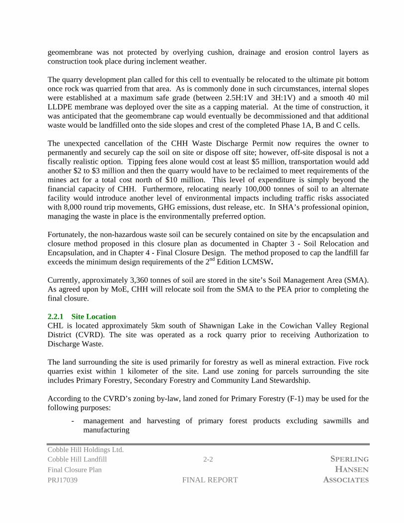
geomembrane was not protected by overlying cushion, drainage and erosion control layers as construction took place during inclement weather. The quarry development plan called for this cell to eventually be relocated to the ultimate pit bottom once rock was quarried from that area. As is commonly done in such circumstances, internal slopes were established at a maximum safe grade (between 2.5H:1V and 3H:1V) and a smooth 40 mil LLDPE membrane was deployed over the site as a capping material. At the time of construction, it was anticipated that the geomembrane cap would eventually be decommissioned and that additional waste would be landfilled onto the side slopes and crest of the completed Phase 1A, B and C cells. The unexpected cancellation of the CHH Waste Discharge Permit now requires the owner to permanently and securely cap the soil on site or dispose off site; however, off-site disposal is not a fiscally realistic option. Tipping fees alone would cost at least $5 million, transportation would add another $2 to $3 million and then the quarry would have to be reclaimed to meet requirements of the mines act for a total cost north of $10 million. This level of expenditure is simply beyond the financial capacity of CHH. Furthermore, relocating nearly 100,000 tonnes of soil to an alternate facility would introduce another level of environmental impacts including traffic risks associated with 8,000 round trip movements, GHG emissions, dust release, etc. In SHA’s professional opinion, managing the waste in place is the environmentally preferred option. Fortunately, the non-hazardous waste soil can be securely contained on site by the encapsulation and closure method proposed in this closure plan as documented in Chapter 3 - Soil Relocation and Encapsulation, and in Chapter 4 - Final Closure Design. The method proposed to cap the landfill far exceeds the minimum design requirements of the 2nd Edition LCMSW. Currently, approximately 3,360 tonnes of soil are stored in the site’s Soil Management Area (SMA). As agreed upon by MoE, CHH will relocate soil from the SMA to the PEA prior to completing the final closure. 2.2.1 Site Location CHL is located approximately 5km south of Shawnigan Lake in the Cowichan Valley Regional District (CVRD). The site was operated as a rock quarry prior to receiving Authorization to Discharge Waste. The land surrounding the site is used primarily for forestry as well as mineral extraction. Five rock quarries exist within 1 kilometer of the site. Land use zoning for parcels surrounding the site includes Primary Forestry, Secondary Forestry and Community Land Stewardship. According to the CVRD’s zoning by-law, land zoned for Primary Forestry (F-1) may be used for the following purposes:
- management and harvesting of primary forest products excluding sawmills and manufacturing

Cobble Hill Holdings Ltd. Cobble Hill Landfill 2-3 SPERLING
Final Closure Plan HANSEN
PRJ17039 FINAL REPORT ASSOCIATES
- extraction, crushing and milling of aggregate material - single family residential - agriculture, horticulture, silviculture - home based business - bed and breakfasts - secondary suite on parcels less than 10.0 hectares - secondary suite or secondary dwelling on parcels greater than 10.0 hectares
Figure 1-1 presented in the previous chapter is a Google Earth image of the Cobble Hill Quarry and Landfill and surrounding land use. Neighbouring quarries and logging blocks are clearly visible. The Primary Forestry lands adjacent to the site are owned by the CVRD and include the Stebbings Road Community Forest. Two residences exist on land located approximately 320 meters southeast of the site. Land zoned for Secondary Forestry includes similar land uses as Primary Forestry; however, aggregate mining is not permitted. There are five one hectare parcels zoned for Secondary Forestry northeast of the site. Land zoned for Community Land Stewardship exists 200 meters south of the site extending to 2.5 kilometers south. This zone includes a variety of land uses ranging from ecological conservation, single family dwellings, bed and breakfasts, home based business, equestrian centers, daycare, convenience store, schools and more. An Industrial Park also exists in the vicinity of the site, located off Shawnigan Lake Road. 2.2.2 Legal The legal description of the land parcel for the Shawnigan Lake Quarry is as follows: Parcel I.D.: 026-226-502 Legal: Lot 23, Plan VIP78459, Blocks 156,201,323, Malahat Land District. 2.2.3 Permit On August 21, 2013, the CHH Landfill, received Permit 105809 to discharge waste. The permit authorized discharge of contaminated soil. The permit allowed for soil treatment onsite, however, CVRD municipal bylaws, according to BC Supreme Court, indicate that soil treatment is not within the respective land use; therefore, soil treatment was not conducted onsite. A covered soil management area exists for soils contaminated with hydrocarbons, styrene, methyl tertiary butyl ether, volatile petroleum hydrocarbons, light and heavy extractable petroleum hydrocarbons, polycyclic aromatic hydrocarbons, chlorinated hydrocarbons, phenols, chloride, sodium, and glycols.

Cobble Hill Holdings Ltd. Cobble Hill Landfill 2-4 SPERLING
Final Closure Plan HANSEN
PRJ17039 FINAL REPORT ASSOCIATES
The permit allowed discharge of contaminated soils and ash into a lined Landfill cell. Contaminant levels less than Hazardous Waste, as regulated by the Hazardous Waste Regulation, were permitted for landfilling. Contaminants permitted include those listed above as well as soils impacted by metals, dioxins, and furans. Effluent from the site was permitted at a maximum discharge rate of 274 cubic meters per day, and had to meet British Columbia Approved Water Quality Guidelines for Drinking Water and Freshwater Aquatic Life. The above-mentioned rate was under review by the Ministry of Environment to allow for additional discharge during high storm events. The Quarry permit and Waste Discharge permit are no longer in place. 2.2.4 Geology and Hydrogeology The site is underlain by Wark Gneiss bedrock – a formation composed of massive and gneissic metadiorite, metagabbro, and amphibolites (Active Earth Engineering Ltd., 2012). The site also includes a hard, granitic bedrock exposure. There are no faults located under the site; two faults occur three kilometers to the southwest and six kilometers to the northwest. The local flow regime is that of fractured flow through bedrock aquifers. There is no bedrock aquifer mapped directly underneath the site, however there are two bedrock aquifers located near the site: Spectacle Lake/Malahat Bedrock Aquifer and Shawnigan Lake/Cobble Hill Bedrock Aquifer. The site is serviced by an on-site groundwater well. Due to previous quarrying at the site, there are no native soils in the immediate area. However, soils surrounding the site originate from glacial till. 2.2.5 Climate The temperature and precipitation data for 1981 to 2010 were sourced from the Environment Canada website using the Lake Cowichan weather station. The nearest weather station is located at Shawnigan Lake, B.C. about 15 km to the North of the site, however the Lake Cowichan weather station has been chosen as a reference site as it provides a conservative representation of annual rainfall and thus provides a “worst case scenario” baseline for our analysis. The climate data is summarized in Table 2-1 below. The average annual precipitation is approximately 2047.5 mm with approximately 1975.6 mm falling as rain and 72.0 cm falling as snow. The average annual temperature is approximately 9.8oC with an average peak of 18.1oC occurring in August and the minimum average temperature of 2.5oC occurring in December. The maximum average snowfall of 19.8 cm occurs in January. Table 2-1 presents the average monthly precipitation and temperature for the Lake Cowichan weather station.

Cobble Hill Holdings Ltd. Cobble Hill Landfill 2-5 SPERLING
Final Closure Plan HANSEN
PRJ17039 FINAL REPORT ASSOCIATES
Table 2-1 Climate Data for Cowichan Lake station, 1981 to 2010 (Environment Canada, 2017) Parameter Jan Feb Mar Apr May Jun Jul Aug Sep Oct Nov Dec Year
Rainfall (mm) 327.3 206.2 209.2 135.9 85.2 57.2 34.7 40.2 51.7 212.5 334.8 280.9 1975.6 Snowfall (cm) 19.8 19.8 7.0 1.5 0.3 0.0 0.0 0.0 0.0 0.8 8.4 14.4 72.0 Precipitation (mm) 347.0 226.0 216.2 137.4 85.4 57.2 34.7 40.2 51.7 213.3 343.2 295.3 2047.5 Daily Average (°C) 3.2 4.0 6.2 8.6 12.1 15.0 17.8 18.1 15.2 9.8 5.4 2.5 9.8
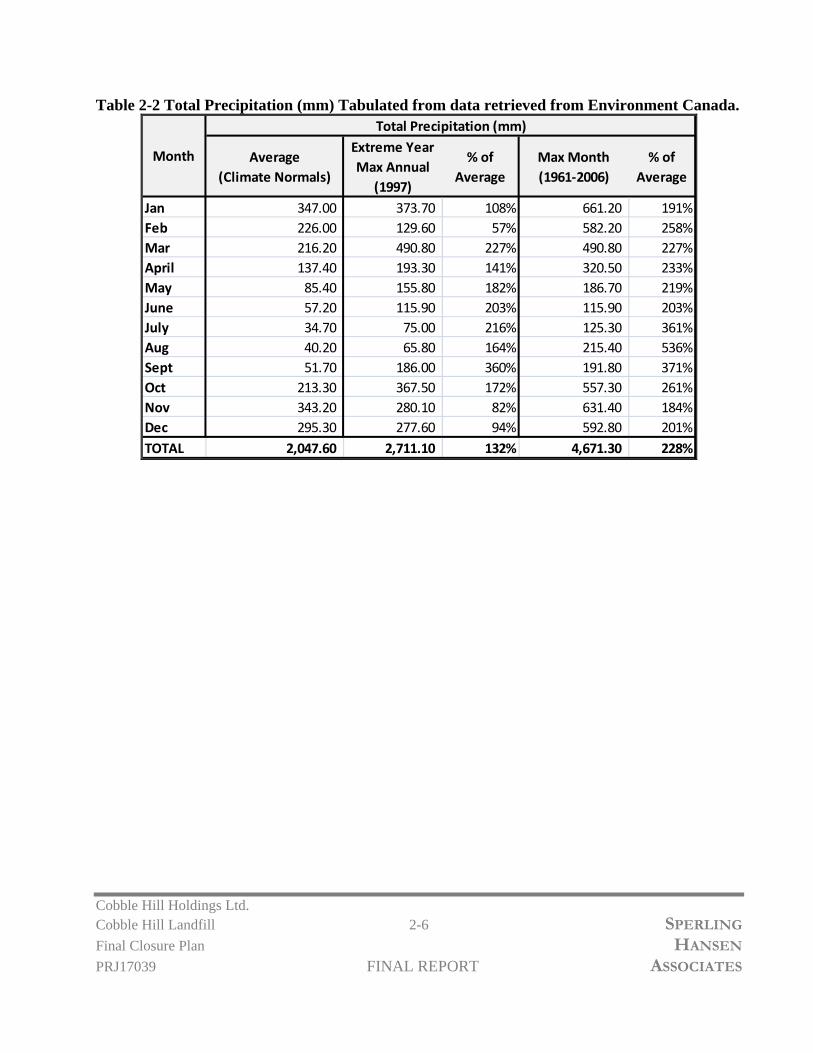
In order to complete hydrologic modelling for a 1 in 200-year storm event, including snowmelt and multi-day precipitation, the IDF curve for the Lake Cowichan Environment Canada Climate station, was utilized, as presented in Figure 2-3. The maximum 1 in 100 year 24 hour storm intensity for the area is estimated at 6.5 mm per hour, or 156 mm/day. Although the 200 year intensity is not listed, based on the logarithmic progression of the graph, an intensity of about 7.5 mm per hour appears appropriate, resulting in a design rainfall intensity of 180 mm/day. Accounting for 6 mm of snow melt/day increases the design intensity to 186 mm/day. This is similar to the 200 year intensity outlined by WSP in the Addendum: Review of Contact and Non-Contact Water Management Systems as 7 mm/hr or 168.7mm/day. A further analysis of appropriate hydrologic modelling for the worst case scenario Surface Water Management is found in Chapter 6. For design of leachate management systems, a longer term wet season scenario is more appropriate. For this, monthly climate normals were reviewed. The average precipitation values represent the average total precipitation from the Canadian Climate Normals. The “Extreme Year” precipitation was found by compiling annual climate data and discovering the year with the maximum annual precipitation. The overall percent difference between the max year and the average climate is 132% or a factor of 1.3. The “Max Month” data represents maximum total precipitation for each month recorded over a period of 1961 – 2006. In an extreme situation, where each maximum month is summed for an extreme maximum annual precipitation, the overall percent difference to average is 228% or 2.3. As this is an extreme over-estimate, SHA has used a conservative multiplier of 1.5 for hydrologic modelling of infrastructure at the site.
Cobble Hill Holdings Ltd. Cobble Hill Landfill 2-6 SPERLING
Final Closure Plan HANSEN
PRJ17039 FINAL REPORT ASSOCIATES
Table 2-2 Total Precipitation (mm) Tabulated from data retrieved from Environment Canada.
Average
(Climate Normals)
Extreme Year
Max Annual
(1997)
% of
Average
Max Month
(1961‐2006)
% of
Average
Jan 347.00 373.70 108% 661.20 191%Feb 226.00 129.60 57% 582.20 258%Mar 216.20 490.80 227% 490.80 227%April 137.40 193.30 141% 320.50 233%May 85.40 155.80 182% 186.70 219%June 57.20 115.90 203% 115.90 203%July 34.70 75.00 216% 125.30 361%Aug 40.20 65.80 164% 215.40 536%Sept 51.70 186.00 360% 191.80 371%Oct 213.30 367.50 172% 557.30 261%Nov 343.20 280.10 82% 631.40 184%Dec 295.30 277.60 94% 592.80 201%TOTAL 2,047.60 2,711.10 132% 4,671.30 228%
Month
Total Precipitation (mm)

3
2
0
320
3
2
0
325
330
3
3
0
3
3
0
3
3
0
3
3
0
3
3
5
3
3
5
3
4
0
3
4
0
325
3
3
0
3
3
5
3
4
0
3
4
0
3
4
0
3
3
0
3
3
0
3
3
0
335
3
3
5
3
4
0
3
4
0
335
330
3
3
0
3
3
0
340
330
3
2
8
329
3
3
1
3
3
2
333 334
3
3
5
3
3
6
3
2
0
3
2
5
3
3
5
3
3
0
3
4
0
335
3
4
0
3
2
5
3
4
1
3
3
9
325
3
2
4
3
4
0
3
4
0
3
3
5
3
4
0
3
3
8
3
3
9
3
4
1
3
4
5
3
4
6
3
4
5
3
3
9
3
3
5
340
3
4
5
S
T
E
B
B
I
N
G
S
R
O
A
D
BERM
BERM
SC
ALE
SC
ALE
OF
FIC
E
SC
ALE
H
OU
SE
ST
AF
F A
ND
VIS
ITO
R P
AR
KIN
G
S
O
IL
M
A
N
A
G
E
M
E
N
T
A
R
E
A
(
S
M
A
)
C
O
V
E
N
A
N
T
B
O
U
N
D
A
R
Y
muster point
T
R
U
C
K
W
A
S
H
S
H
A
W
N
IG
A
N
C
R
E
E
K
Lot 23
B
L
O
C
K
W
A
L
L
CONTACT WATER
POND
P
R
O
P
E
R
T
Y
L
IN
E
S
E
T
T
L
IN
G
P
O
N
D
Lot 22
L
o
t 2
2
V I P 7 8 4 5 9
R
E
F
E
R
E
N
C
E
P
L
A
N
V
I
P
7
8
4
6
9
CO
VE
NA
NT
BO
UN
DA
RY
pow
er pole
O
V
E
R
H
E
A
D
H
Y
D
R
O
L
I
N
E
P
O
N
D
S
H
A
W
N
I
G
A
N
C
R
E
E
K
O
V
E
R
H
E
A
D
H
Y
D
R
O
L
IN
E
455,100
455,200
455,300
455,400
5,377,500
5,377,600
5,377,700
5,377,800
5,377,900
5,378,000
5,378,100
345
3
5
0
3
4
0
3
3
5
3
3
5
3
3
5
3
4
0
330
325
330
335
340
335
330
325
320
315
310
325
330
335
330
330
3
3
0
3
3
0
3
3
0
3
3
1
3
4
3
3
4
4
3
4
5
3
4
2
3
4
3
3
4
1
3
4
2
3
4
2
3
4
3
3
4
0
3
3
8
3
3
7
3
3
6
3
3
5
3
4
0
3
4
0
3
4
0
3
3
5
3
3
5
3
3
0
3
3
1
3
3
5
(D
E
C
O
M
IS
S
IO
N
E
D
)
MINE GATE
MAIN GATES
SEDIMENTATION
POND
LEACHATE TANK
STORES 1
SCALE HOUSE
LEACHATE COLLECTION
RUN-ON DIVERSION
DITCH
CLEAN RUN-OFF DISCHARGE
TO QUARRY FLOOR
SURFACE WATER DITCH
LINER EXTENTS
MW - 5S / 5D
MW - 2
MW - 3S / 3D
MW - 1S / 1D
MW - 4
MW - 6
SW - 1
SW - 4
AIR SAMPLING STATION
86152
PERMANENT
ENCAPSULATION
AREA
LEAK DETECTION TANK
LEGEND:
CLIENT:
PROJECT:
TITLE:
SCALE:
DESIGNED
DRAWN
CHECKED
DRAWING NO:
SG
TS
DATE: PROJECT NO:
FIGURE 2-1
COBBLE HILL LANDFILL FINALCLOSURE PLAN
COBBLE HILL HOLDINGS LTD.
EXISTING TOPOGRAPHY &INFRASTRUCTURE
1:2,000 2017/05/25 PRJ 17039yyyy/mm/dd
(604) 986-7734(604) 986-7723
North Vancouver, B.C. V7J 1J3#8 - 1225 East Keith Road
Environmental Monitoring
Design & Operations Plans
Landfill Services Group
Fax:Phone:
Landfill Closure
Landfill Siting
SSOCIATES
S PERLING ANSENHA
5m EXISTING CONTOUR
1m EXISTING CONTOUR
5m AS-BUILT CONTOUR
1m AS-BUILT CONTOUR
ROAD
SURFACE WATER DITCH
PROPERTY LINES
N
CREEK
LANDFILL EXTENTS
MONITORING WELLS
WATER WELL
SURFACE WATER STATION
AIR SAMPLING STATION

325
3
3
0
3
3
0
3
4
0
335
330
3
3
0
3
3
0
3
4
1
3
3
9
325
3
2
4
3
4
0
3
4
0
3
3
5
3
4
5
3
4
6
3
4
5
P
R
O
P
E
R
T
Y
L
IN
E
S
E
T
T
L
IN
G
P
O
N
D
O
V
E
R
H
E
A
D
H
Y
D
R
O
L
I
N
E
O
V
E
R
H
E
A
D
H
Y
D
R
O
L
IN
E
LEACHATE DETECTION STORAGE TANK
INV. 329.964 m
455,100
455,200
5,377,600
5,377,700
5,377,800
345
3
5
0
3
4
2
3
4
3
3
4
0
3
3
8
3
3
7
3
3
6
3
3
5
3
4
0
3
4
0
3
4
0
3
3
5
3
3
5
3
3
0
3
3
1
3
3
5
LEACHATE COLLECTION
SYSTEM DISCHARGE
LOCATION
RUN-ON DIVERSION
DITCH
CLEAN RUN-OFF DISCHARGE
TO QUARRY FLOOR
SURFACE WATER DITCH
LINER EXTENTS
LEAK DETECTION
STORAGE TANK
INV. 329.664 m
C
E
L
L
1
B
C
E
L
L
1
A
C
E
L
L
1
C
LEGEND:
CLIENT:
PROJECT:
TITLE:
SCALE:
DESIGNED
DRAWN
CHECKED
DRAWING NO:
SG
TS
DATE: PROJECT NO:
FIGURE 2-2
COBBLE HILL LANDFILL FINALCLOSURE PLAN
COBBLE HILL HOLDINGS LTD.
PERMANENTENCAPSULATION AREA
DETAILS
1:750 2017/05/24 PRJ 17039yyyy/mm/dd
(604) 986-7734(604) 986-7723
North Vancouver, B.C. V7J 1J3#8 - 1225 East Keith Road
Environmental Monitoring
Design & Operations Plans
Landfill Services Group
Fax:Phone:
Landfill Closure
Landfill Siting
SSOCIATES
S PERLING ANSENHA
5m EXISTING CONTOUR
1m EXISTING CONTOUR
5m AS-BUILT CONTOUR
1m AS-BUILT CONTOUR
ROAD
SURFACE WATER DITCH
PROPERTY LINES
N
CREEK
LANDFILL LINER EXTENTS

SPERLING
PROJECT NO:DATE:SCALE:PROJECT: TITLE:CLIENT:
NTS 2017/05/29 PRJ1 7039COBBLE HILL LANDFILL
HA SSOCIATES ANSENS PERLING
DRAWING NO:
CHECKED
DRAWN
DESIGNED
yyyy/mm/ddIntensity Duration Frequency (IDF)Data MG
TSFigure 2-3
COBBLE HILL LANDFILLFINAL CLOSURE PLAN IB
Cobble Hill Holdings Ltd.

Cobble Hill Holdings Ltd. Cobble Hill Landfill 3-1 SPERLING
Final Closure Plan HANSEN
PRJ17039 FINAL REPORT ASSOCIATES
3. SOIL RELOCATION AND ENCAPSULATION & INFRASTRUCTURE DECOMMISSIONING Currently, one completed and capped waste soil cell exists onsite at CHHL (referred to as the Permanent Encapsulation Cell). Currently this cell contains 94,235 tonnes of soil; of which, 44,722 tonnes were received in 2015 and 49,513 tonnes were received in 2016. Cobble Hill Holdings Ltd. has been granted permission to relocated 3,360 tonnes of soil from the Soil Management Area (SMA) to the Permanent Encapsulation Area (PEA) to enable final landfill closure activities. The total amount of soil that will be contained in the PEA for final closure will be 97,595 tonnes. Described below are SHA’s recommendations on how to relocate the contaminated soil and how to complete the lined permanent cell encapsulation to ensure that it will be protective of the environment and that the closure will be compliant with the new LCMSW.
3.1 Contaminated Soil Relocation and Encapsulation Plan
Although it was CHH’s long term plan to eventually relocate the existing PEA to a lower portion of the quarry to expose additional bedrock resources, the PEA was constructed following the approved containment design that exceeded the applicable standards in the 1993 LCMSW. Because the plan was to relocate the PEA at some point in the future, the north and east slopes were originally developed at slope angles as steep as 2H:1V. Prior to deploying the 40 mil LLDPE cap, SHA requested that all slopes be graded to angles of 2.5H:1V or flatter. Recognizing, that the PEA now needs to be converted to a long term closure configutation, it is imperative that the geomembrane can be covered with protective soil layers. To ensure stability, and to achieve compliance with the 2016 LCMSW, the PEA north and east side slopes will be regraded to 3H:1V grades using cut and fill methods. This will require the landfill toe to be pushed out. Technical details on how that will be achieved are presented in Chapter 4. As detailed further in Chapter 4, to achieve the regrade, it will be necessary to remove the existing smooth liner on the north and east slopes of the PEA (existing liner on the crest will remain in place), and to extend the basal liner and leachate collection and leak detection system at the toe to provide the necessary room to establish the 3H:1V subgrade slopes prior to deployment of the new final cover system. Details of the liner and leachate collection system extension are shown in Figure 3-1. The shot rock seepage layer, the 1,000 mm thick compacted clay secondary liner, the lower sand leak detection layer, and the 40 mil LLDPE geomembrane will be extended as shown. The liner extension will utilize 40 mil double textured LLDPE to provide additional shear resistance at the landfill toe.

Cobble Hill Holdings Ltd. Cobble Hill Landfill 3-2 SPERLING
Final Closure Plan HANSEN
PRJ17039 FINAL REPORT ASSOCIATES
The new liner extension will be double wedge or extrusion welded to the existing 40 mil LLDPE liner and detailed QA/QC will be undertaken that this critical seam is free of defects and leaks. The liner will then be covered with the upper 200 mm thick sand cushion. A new leak detection perforated collector pipe will be keyed into the secondary clay liner. The DR-17 HDPE perforated pipe collector will have a nonwoven geotextile filter and and 5-25 mm round drain rock pipe surround, with clean outs at approximately 50 m spacings. The plan view layout of the leachate collection system upgrade is shown in Figure 3-2. To create the desired 3H:1V slopes which are stipulated in the new landfill criteria,and which will have the desired slope stability factors of safety in the long term, the existing 40 mil LLDPE smooth geomembrane liner on the PEA slopes will be carefully trimmed along the crest alignment and folded back towards the south. The existing liner on the slopes will be removed. Once construction work to extend the basal liner system and associated environmental control layers to the projected 3H:1V line at the landfill toe is complete the existing waste soil within the PEA will be re-sloped and compacted.
3.2 Relocation of Soil from the Soil Management Area (SMA)
Additionally, soil from the SMA (3,360 tonnes of soil or approximately 1,867 m3 based on 1.8 T/m3 for clay type soil) will be incorporated as grading fill into this regrading work. Once re-sloping is complete, which will result in a roughly balanced cut and fill of existing soil within the PEA, the new crest alignment will be further to the south and west relative to its current position. Soil from the SMA will be cleared from the concrete pad using a front end loader and placed into trucks for transport to the PEA. Care will be taken to ensure the soil is not discharged into the environment. Transport of the soil will take place on a dry day to ensure no additional run-off or contact water is created due to precipitation falling on the open PEA. Trucks will carefully be loaded with soil within the SMA to ensure no overfilling takes place and no soil is spilled into the surrounding environment during transport. The loading area will be kept clean to minimize the amount of soil coming in contact with vehicle wheels. The soil will be trucked to the PEA, approximately 250m from the SMA, using the existing crest and toe access roads. Soil will be carefully placed into the PEA to ensure no soil is discharged into the environment. Once the remainder of the soil has been relocated, placed and compacted in 500mm lifts the updated textured geomembrane final cover system will be installed. Further details to the final cover system design are outlined in Chapter 4. Following soil relocation, the SMA (including the existing cover-all structure and ashphalt pad) will be cleaned, washed down and decontaminated. Once decontaminated, the SMA may be de-constructed and removed. Any contact water from the decommissioning process will be directed to

Cobble Hill Holdings Ltd. Cobble Hill Landfill 3-3 SPERLING
Final Closure Plan HANSEN
PRJ17039 FINAL REPORT ASSOCIATES
the existing contact water pond for storage prior to transport offsite for discharge at a regulated liquid waste facility.
3.3 Contact Water Management
During the soil relocation period, any contact water / leachate from the SMA and PEA will continue to be managed using the existing leachate collection system and contact water storage pond. The contact water / leachate management system will be re-constructed and upgraded concurrently with soil relocation. As discussed in Chapter 5, a new double lined leachate storage facility will be constructed near the existing PEA for storage of leachate generated and collected from the PEA. Both the leak detection and leachate storage tanks will be relocated, away from the existing PEA toe, concurrently to allow for final closure construction works. The location of these tanks and associated works is outlined further in Chapter 5. Once the leachate and leak detection tanks and associated conveyance piping are installed and operational, contact water / leachate, sludge and liner system in the existing contact water pond will be removed and transported off site for disposal. The pond will be decommissioned and backfilled with low permeability soil material, which will be compacted in 500 mm lifts until sufficient grades are achieved to ensure no ponding water in the area. Figure 2-1 shows the existing locations of the leachate and leak detection tanks, SMA, PEA and Contact Water Pond. Figure 4-1 outlines the proposed locations of the relocated leachate and leak detection facilities.
3.4 Landfill Design Assessment
As outlined in the Spill Prevention Order MO1701 and South Island Resource Managements As-builts Documents – MOE Comments, the final closure plan should include an assessment of the adequacy of the existing facility, including: seepage blanket, landfill base liner, anchor trenches, leachate collection and leak detection works, landfill cells and leachate storage upgrades. Basal Seepage Layer: SHA was not involved in the detailed design nor construction QA/QC of those systems. We can only reflect on the commentary of those responsible for constructing the basal seepage layer. The base of the landfill is being developed in a rock quarry. We have been assured by representatives from SIRM that a continuous layer of shot rock was achieved by overblasting the rock quarry a minimum depth of 2.0 m below design grade prior to placement of the clay barrier. Overblasting of the high quality Wark Gneiss bedrock has opened up fractures that now allow groundwater to permeate more freely than was the case in the past. Depth to Water Table: The PEA was designed to be in conformance with the applicable guidelines and regulations of the day. Waste Discharge Permit 105809 does not provide any requirements on the nature of the containment structures. As the containment facility for the PEA was constructed in

Cobble Hill Holdings Ltd. Cobble Hill Landfill 3-4 SPERLING
Final Closure Plan HANSEN
PRJ17039 FINAL REPORT ASSOCIATES
2014 and 2015 , the applicable guidelines of the day were the 1993 Landfill Criteria. This criteria recommended that natural control landfills be sited in areas where the water table is at least 1.2 m below ground. There is no comparable guidance for engineered landfills in the 1993 Landfill Criteria. The 2016 LCMSW stipulates that all new landfills and lateral expansions be sited in areas where the water table is at least 1.5 m below ground. Although this new guidance does not apply, ground water monitoring of the water table undertaken by SIRM has indicated that the water table is consistently several meters below the ground surface. Previous analysis of deep monitoring wells has shown that the potentiometric surface in the confined bedrock aquifer is near the quarry floor (see Active Earth drawing Figure 6, Detailed Cross Section B (at Quarry) 2012-02-21. It is important not to confuse this confined bedrock aquifer piezometric surface with the water table. The water table has consistently been observed several metres below the pit floor when drilling blast holes, according to SIRM representatives. Clay Secondary Liner: The PEA is lined with a 1 m thick impervious brown marine clay barrier sourced from the Victoria area. This clay contains about 70% fines pasing the No. 200 sieve (0.074 mm) with 20 to 30% clay content. Although permeability testing was not conducted on this clay by Golder Associates, grain size analysis was conducted. SHA has used brown marine clay from the Victoria area on other projects at Hartland Landfill and the permeability of that clay, which is likely very similar to the material used at CHH was 2.8x10⁻⁸ cm/s. The minimum requirement in the landfill criteria is a 1 m thick clay barrier with a K less than 1x10⁻⁷ cm/s or an equivalent geomembrane. Thus the secondary clay liner alone complies with the 1993 Landfill Critiera liner requirement. 40 mil LLDPE Primary Liner: In addition, the CHHL PEA is lined with a 40 mil geomembrane which serves as the primary liner. The double liner approach adopted by CHH makes the PEA much more secure than most MSW landfills in B.C. that contain far more hazardous wastes. Furthermore, in SHA’s opinion, the double liner is equivalent to the liner requirements of the 2016 LCMSW which call for a 60 mil HDPE primary liner and a 750 mm thick compacted clay liner. The CHHL membrane is a little thinner and the clay liner is a little thicker. The 2016 LCMSW recommends that a 60 mil HDPE liner be used as the primary geomembrane. This recommendation was made by SHA when originally developing the 2016 LCMSW for the MoE in recognition of research undertaken by Dr. Kerry Rowe which revealed that geomembrane liners tend to deteriorate rapidly when subject to elevated temperatures. This is a particular concern in biologically active landfills that receive typical municipal solid waste, but it is not a concern at CHH landfill because all of the soils placed into PEA are biologically inert soils that will not generate elevated temperatures. Therefore, the primary geomembrane will be subject to far less thermal stress and a 40 mil thickness will be adequate to provide the desired long term performance.

Cobble Hill Holdings Ltd. Cobble Hill Landfill 3-5 SPERLING
Final Closure Plan HANSEN
PRJ17039 FINAL REPORT ASSOCIATES
Given that the geomembrane will not be subject to elevated temperatures and that it is well cushioned top and bottom by 200 mm thick sand cushion layers, a service life in excess of 100 years is anticipated. However, as SHA has not had any involvement in the construction of this liner we cannot warrant the liner integrity or service life, but only offer a professional opinion that a long service life is expected. Texturing of Liner: The existing membrane utilized for both the bottom liner and the capping layer is smooth geomembrane. Although double textured geomembrane is much preferred and would have been selected by SHA had we been involved in the detailed design and material selection, the existing materials will achieve the desired level of stability on the base and crest areas of the fill because the smooth sheet is encapsulated in sand friction layers top and bottom. Smooth membrane cannot be used on capping of the 3H:1V side slopes of the PEA. In those areas, SHA has required that the smooth membrane be replaced with a double textured 40 mil LLDPE liner to achieve the necessary factors of safety against slope instability. Additional details are provided in Chapter 4 – Final Closure Design and Chapter 7 – Geotechnical Considerations and Slope Stability. Leachate Collection Layer: The leachate collection layer was constructed of a 300 mm thick sand layer built at 2% grade and with perforated leachate collection pipes. As the PEA has been fully encapsulated and will remain fully encapsulated once the new final cover system is constructed, there will be no new precipitation entering the liner, other than minimum quantities of water through any undetected liner defects. Typically, such infiltration is minimal. Currently, the amount of seepage being collected daily is averaging about 500 L/day. Over the approximately 1 Ha landfill footprint, this translates to a seepage rate of 1.8 cm/year. We are confident that the vast majority of the leachate being captured is actually pore water being squeezed out of the soil through consolidation and that leakage is absolutely minimal. As the landfill is closed, the sand drainage layer is considered more than adequate to capture and convey any future seepage that will exit the waste fill. The seepage rate is expected to continue to decline with time. Soil Filter: A geotextile filter was not installed in the PEA above the sand drainage layer. Hemmera has raised concerns about this alleged omission. There is no requirement for a filter layer in the 1993 Landfill Criteria. The 2016 LCMSW guidance is for installation of a geotextile filter layer above the drainage blanket, or installation of an engineered graded soil filter. Based on practical experience with geotextile clogging, SHA’s preferred approach to the design of leachate collection systems is to avoid geotextile filter layers and to instead utilize graded soil filters which are less prone to clogging. In this case, the 300 mm sand layer is expected to provide a high degree of filtration capacity and should be effective in preventing migration of fines toward the leachate collector. Furthermore, given that there is no new water entering the PEA there is no opportunity for water to carry the fines into the drainage layer and ultimately into the leachate collection system.

Cobble Hill Holdings Ltd. Cobble Hill Landfill 3-6 SPERLING
Final Closure Plan HANSEN
PRJ17039 FINAL REPORT ASSOCIATES
Leachate Collection Piping: As part of the closure works, SHA has designed two new leachate collectors, one for the primary leachate collection layer above the liner and a second for the leak detection layer below the liner. Both collectors will be 100 mm HDPE DR-17 perforated pipes that will easily be able to withstand anticipated loads. The pipes will be embedded in 25-50 mm clear round drain rock. The drainage blanket extension will be constructed of 5 – 25 mm clear drain rock isolated from above by a non-woven geotextile filter. Leachate collection piping has not been installed in a herringbone fashion within the drainage layer in this case because it was not required in the 1993 Landfill Criteria. The minimum drainage layer requirement in the 1993 Criteria is a 300 mm thick sand drainage layer. Furthermore, the 300 mm sand drainage layer has more than enough hydraulic capacity to convey any collected leachate to the landfill toe as the PEA is fully encapsulated with negligible leachate flow. Grading of Permanent Encapsulation Area: The design objectives of the PEA have changed as a result of the recently issued Spill Prevention Order. Since a permanent cover system is now to be constructed and long term stability of that cover system must be assured the side slopes of the PEA must be reconfigured. The final contours of the PEA have been adjusted to achieve the following objectives:
Maximum final grades of 3H: 1V
Minimum final grades of 10H: 1V (10%)
Surface water crest and toe ditch
Promote surface water run off
Keep clean water clean With the addition of soil from the SMA to the PEA and regrading of the existing PEA geometry on the east and north slopes, the final contours for CHL will be established at the desired 3H:1V grade. Elevations will range from 330 m at the landfill toe to 343 m at the landfill crest along the eastern edge of the PEA. An 8m wide access road along the northern toe of the PEA has been included providing access to the leachate and leak detection storage tanks as well as the western portion of the cell. The existing settling pond located to the north of the site will manage onsite clean run-off from closed areas and clean quarry floor to knock out any suspended sediments prior to discharge. The current state of the PEA on site includes slopes at approximately 2.5H:1V, specifically along the eastern slope. SHA has developed a strategy to remove the existing 40 mil LLDPE Smooth

Cobble Hill Holdings Ltd. Cobble Hill Landfill 3-7 SPERLING
Final Closure Plan HANSEN
PRJ17039 FINAL REPORT ASSOCIATES
Geomembrane from the sloped areas and to perform a regrade using onsite material with a cut and fill operation, supplemented with additional soil fill from the SMA to provide appropriate grades of 3H:1V to achieve subgrade elevations before the final cover system is installed.

EXISTINGSAND CUSHION LAYER
EXISTINGWASTE SOIL
EXISTING 40mil LLDPEGEOMEMBRANE BASE LINER
2
1
COMPACTED
LOW PERMEABILITY
SOIL
EXISTING SURFACE
300
EXISTING 100 mmPVC PERFORATED LEACHATE PIPE
INV. ELEVATION 329.964 m
2 x 100 mm Ø DR17 HPDESOLID PIPE
SEE DRAWING 5-4 FORTWIN PIPE TRENCH
TIE-IN LOCATIONPIPES TO BE WELDEDIN THE FIELDAND PRESSURE ANDHYDRAULICALLY TESTED
EXISTING 100 mmPVC PERFORATED LEAK DETECTION PIPE
INV. ELEVATION 329.664 m
EXISTING LEACHATE ANDLEAK DETECTION TRENCH
REFER TO AS-BUILTS IN APPENDIX B
40 mil LLDPE DOUBLETEXTUREDGEOMEMBRANEEXTENSION TO TIE INTOEXISTING 40 mil LLDPEGEOMEMBRANE BASELINER
COVER SYSTEM LINER AND BASALLINER EXTENSION TO TIE-IN AND BEWELDED WITH WEDGE WELDER
200 mm SAND
2%
2%
2%
2%
CLEANOUTS
1.0 m (MIN) SECONDARY CLAY LINER
LEAK DETECTIONSYSTEM EXTENSIONWITH CLAY NOTCH
LEACHATE COLLECTIONSYSTEM EXTENSION
DESIGN SUBGRADE
SURFACE
EXISTING SURFACE
SURFACE
CLEANOUT
3
1
8 oz NON-WOVENGEOTEXTILE
200 mm 5-25 mm CLEAR CRUSHGRAVEL DRAINAGE LAYER
EXISTING SEEPAGE BLANKET LAYER
APPROXIMATEBEDROCK SURFACE
SHALLOW DRAINAGE BLANKET MONITORING WELL
THREE PROPOSED WELLS ALONG NORTHERN TOE OF PEA
25 to 50 mm CLEANDRAIN ROCK
12 oz NON-WOVENGEOTEXTILE
LEGEND:
CLIENT:
PROJECT:
TITLE:
SCALE:
DESIGNED
DRAWN
CHECKED
DRAWING NO:
SG/MG
TS
DATE: PROJECT NO:
FIGURE 3-1
COBBLE HILL LANDFILLFINAL CLOSURE PLAN
COBBLE HILL HOLDINGS LTD.
BASE LINER AND LEACHATECOLLECTION SYSTEM
EXTENSION DETAIL
1:50 2017/05/24 PRJ 17039yyyy/mm/dd
(604) 986-7734(604) 986-7723
North Vancouver, B.C. V7J 1J3#8 - 1225 East Keith Road
Environmental Monitoring
Design & Operations Plans
Landfill Services Group
Fax:Phone:
Landfill Closure
Landfill Siting
SSOCIATES
S PERLING ANSENHA
BASE LINER AND LEACHATE COLLECTION SYSTEM EXTENSIONSCALE 1:50

3
3
0
3
3
0
3
3
0
3
3
0
3
4
1
3
3
9
325
3
3
5
P
R
O
P
E
R
T
Y
L
IN
E
O
V
E
R
H
E
A
D
H
Y
D
R
O
L
I
N
E
3
4
2
3
4
3
3
4
0
3
3
8
3
3
7
3
3
6
3
3
5
3
4
0
3
4
0
3
4
0
3
3
5
3
3
5
3
3
0
3
3
1
3
3
5
PROPOSED LEAK DETECTION AND
LEACHATE COLLECTION SYSTEM
EXTENSION
BASE LINER EXTENSION
EXISTING LEACHATE TIE-IN
PROPOSED LEACHATE TIE-IN
EXISTING LEACHATE COLLECTION AND LEAK DETECTION
SYSTEM
EXISTING BASE LINER
EXTENT
EXISTING LEACHATE AND LEAK
DETECTION STORAGE TANKS
PROPOSED LEACHATE AND LEAK
DETECTION STORAGE TANKS
LEGEND:
CLIENT:
PROJECT:
TITLE:
SCALE:
DESIGNED
DRAWN
CHECKED
DRAWING NO:
SG
TS
DATE: PROJECT NO:
FIGURE 3-2
COBBLE HILL LANDFILL FINALCLOSURE PLAN
COBBLE HILL HOLDINGS LTD.
BASE LINER AND LEACHATETOE COLLECTOR EXTENSION
1:500 2017/05/24 PRJ 17039yyyy/mm/dd
(604) 986-7734(604) 986-7723
North Vancouver, B.C. V7J 1J3#8 - 1225 East Keith Road
Environmental Monitoring
Design & Operations Plans
Landfill Services Group
Fax:Phone:
Landfill Closure
Landfill Siting
SSOCIATES
S PERLING ANSENHA
5m EXISTING CONTOUR
1m EXISTING CONTOUR
ROAD
SURFACE WATER DITCH
PROPERTY LINES
N
LANDFILL LINER EXTENTS
PROPOSED SOLIDLEACHATE COLLECTORPIPE
PROPOSED PERFORATEDLEACHATECOLLECTOR/LEACKDETECTION PIPE
EXISTING PERFORATEDLEACHATECOLLECTOR/LEAKDETECTION PIPE
PROPOSED CLEAN-OUT

Cobble Hill Holdings Ltd. Cobble Hill Landfill 4-1 SPERLING
Final Closure Plan HANSEN
PRJ17039 FINAL REPORT ASSOCIATES
4. LANDFILL CLOSURE DESIGN
4.1 Introduction
In this chapter, the final closure design for the PEA is outlined. The objective of this chapter is to provide a detailed guide for construction of an effective closure system at the CHHL. Additionally, comments and concerns from the Ministry of Environment are outlined and addressed. Finally, a conceptual schedule for closure construction is outlined based on the required completion date of October 31st, 2017. To our knowledge, the following is a list of concerns identified by MoE and addressed in SHA’s new permanent encapsulation closure design:
Contingency measures to address any failure of the works or escape or spill of leachate or contaminated soil into the environment.
Leak detection system collection and piping system to be adequately notched into the secondary clay basal liner at the toe of the landfill slope to capture all potential leakage and non-contact infiltration from the surface of the underlaying clay layer.
Provide all as-built cross sections (N-S & E-W) for each cell including basal liner system, clay liner extents, and connections between cells 1A, 1B and 1C. – Completed by SIRM and included in Appendix B, attached.
Provide QP opinion and sign off on the difference in base liner thickness, material, and expected lifespan relative to the use of 40mil LLDPE vs. 60mil HDPE in LCMSW (discussed in Chapter 3)
Provide QP opinion and sign off on the adequacy of not installing geotextile above the sand drainage layer to minimize fines intrusion into the leachate collection system (discussed in Chapter 3)
Provide QP opinion and sign off on the adequacy of the existing cover liner thickness and type (40mil LLDPE smooth non-textured) relative to the use of textured geomembrane or geocomposite equivalent to a 600 mm barrier layer with hydraulic conductivity equal to or less than 1x10⁻⁷ cm/sec as specified in the LCMSW. As well, the use of smooth non-textured geomembrane should be re-evaluated before the final cover started.
Have continuous QP inspection and documentation of all work completed on the PEA closure.

Cobble Hill Holdings Ltd. Cobble Hill Landfill 4-2 SPERLING
Final Closure Plan HANSEN
PRJ17039 FINAL REPORT ASSOCIATES
4.2 Final Cover Objectives
The purpose of final closure of any landfill is to put in place the necessary environmental control systems to effectively manage leachate, surface water and landfill gas (not present in this case). A well-designed closure system should provide the following benefits:
Isolation of refuse preventing direct contact with humans and vectors.
Minimization of infiltration and leachate production through diversion and run-off.
Prevention of leachate breakouts at the landfill toe and on side slopes.
Protection of the cover from erosion through maintenance of a sustainable vegetative community.
In developing the final cover design for CHL to meet the above objectives, the local site conditions had to be considered. The types and thickness of soils and other materials selected for the cover were based both on regulatory guidelines as well as site-specific objectives. Key elements considered in the final cover design were:
Leachate minimization objectives could be achieved with a low permeability soil barrier layer with K (hydraulic conductivity) less than 1x10⁻⁷ cm/s or a geomembrane barrier – in this case, both are present to provide maximum environmental protection and to minimize future leachate disposal costs. Hauling of leachate off-site for disposal is very expensive. Therefore, it is in CHH’s best interests to minimize future leachate production as much as practically achievable.
Although not required in the 2016 LCMSW, a drainage layer is being added in the cover system above the barrier layer to prevent head build up and saturation of the top soil and to further enhance cover system performance. This is another prime example of where CHH is going well beyond minimum design standards to ensure that the desired performance will be achieved and the highest possible level of environmental protection will be realized.
An erosion control layer comprised of topsoil at least 150 mm thick, perhaps thicker, should be adopted to protect the underlying barrier layer and to provide a medium that will support vibrant vegetation growth for the areas where a vegetated end use is planned. Where an industrial end use is planned, the erosion control layer can be substituted by a pavement or gravel layer.
4.3 Regulatory Requirements
Regulatory requirements for landfill closure have been stipulated in the 2016 LCMSW. The key requirements that dictate design of the final cover system are summarized below:
* The final cover barrier layer shall consist of a minimum of 600 mm of low permeability (<1x10⁻⁷ cm/s) compacted soil (or equivalent) cap.

Cobble Hill Holdings Ltd. Cobble Hill Landfill 4-3 SPERLING
Final Closure Plan HANSEN
PRJ17039 FINAL REPORT ASSOCIATES
* The barrier layer shall be protected with a minimum 150 mm thick topsoil layer with approved vegetation established.
* Final cover shall be sloped at a minimum of 4%, to promote surface water runoff, to a maximum slope of 33%.
* Surface water runoff shall be directed outside of the leachate collection system. In order to provide a high degree of security, the current cover system described in this plan exceeds the minimum requirements of the MOE landfill criteria, as described further in Section 4.7. In particular, the engineered cover system being proposed to fully encapsulate the PEA will have performance levels that will result in several orders of magnitude less leakage than the minimum cover system design stipulated in the LCMSW. By controlling pore pressure through internal drainage, the cover system will be at far less risk of slope failure on the geomembrane. By adopting a thicker top soil horizon, the cover system will support a broader diversity of vegetation which will reduce the risk of long term erosion damage and root penetration.
4.4 Earthworks and Environmental Controls to be Completed prior to Final Cover System Construction
As documented in Chapter 3, SHA has recommended that the side slopes of the PEA be cut back to 3H:1V grades to ensure long term slope stability. The updated grading plan for the PEA is shown in Figure 4-1. As mentioned previously in this report, a number of work tasks need to be completed prior to the final cover system installation to ensure stability of the final cover and environmental protection. SHA envisions sequencing the following work tasks to complete the final closure of the PEA: (reference to Figure 4-3 will aid in understanding the tasks outlined below).
1. Trim existing liner along the PEA crest alignment, roll back existing smooth LLDPE liner on the crest and remove the existing liner on the landfills’ east and north slopes to allow for re-grading of slopes to 3H:1V.
2. Reshape the crest run-off containment ditch further to the south beneath liner.
3. Grading and earthworks to extend the secondary basal barrier clay layer (min 1,000 mm thick) north and east overtop of the existing blast rock seepage layer to the 3H:1V slope projection line.
4. Tie-in and extend the existing leachate and leak detection system discharge piping north to proposed leachate storage facility.
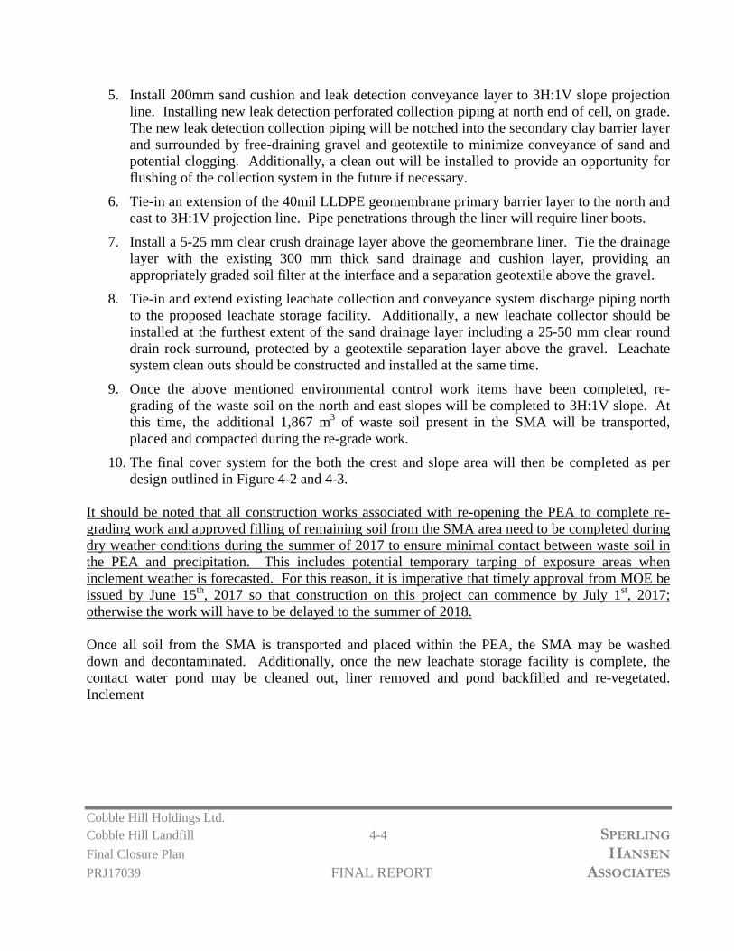
Cobble Hill Holdings Ltd. Cobble Hill Landfill 4-4 SPERLING
Final Closure Plan HANSEN
PRJ17039 FINAL REPORT ASSOCIATES
5. Install 200mm sand cushion and leak detection conveyance layer to 3H:1V slope projection line. Installing new leak detection perforated collection piping at north end of cell, on grade. The new leak detection collection piping will be notched into the secondary clay barrier layer and surrounded by free-draining gravel and geotextile to minimize conveyance of sand and potential clogging. Additionally, a clean out will be installed to provide an opportunity for flushing of the collection system in the future if necessary.
6. Tie-in an extension of the 40mil LLDPE geomembrane primary barrier layer to the north and east to 3H:1V projection line. Pipe penetrations through the liner will require liner boots.
7. Install a 5-25 mm clear crush drainage layer above the geomembrane liner. Tie the drainage layer with the existing 300 mm thick sand drainage and cushion layer, providing an appropriately graded soil filter at the interface and a separation geotextile above the gravel.
8. Tie-in and extend existing leachate collection and conveyance system discharge piping north to the proposed leachate storage facility. Additionally, a new leachate collector should be installed at the furthest extent of the sand drainage layer including a 25-50 mm clear round drain rock surround, protected by a geotextile separation layer above the gravel. Leachate system clean outs should be constructed and installed at the same time.
9. Once the above mentioned environmental control work items have been completed, re-grading of the waste soil on the north and east slopes will be completed to 3H:1V slope. At this time, the additional 1,867 m3 of waste soil present in the SMA will be transported, placed and compacted during the re-grade work.
10. The final cover system for the both the crest and slope area will then be completed as per design outlined in Figure 4-2 and 4-3.
It should be noted that all construction works associated with re-opening the PEA to complete re-grading work and approved filling of remaining soil from the SMA area need to be completed during dry weather conditions during the summer of 2017 to ensure minimal contact between waste soil in the PEA and precipitation. This includes potential temporary tarping of exposure areas when inclement weather is forecasted. For this reason, it is imperative that timely approval from MOE be issued by June 15th, 2017 so that construction on this project can commence by July 1st, 2017; otherwise the work will have to be delayed to the summer of 2018. Once all soil from the SMA is transported and placed within the PEA, the SMA may be washed down and decontaminated. Additionally, once the new leachate storage facility is complete, the contact water pond may be cleaned out, liner removed and pond backfilled and re-vegetated. Inclement

Cobble Hill Holdings Ltd. Cobble Hill Landfill 4-5 SPERLING
Final Closure Plan HANSEN
PRJ17039 FINAL REPORT ASSOCIATES
4.5 Elements of the Final Cover Design on Landfill Crest
To achieve the objectives outlined previously, a minimum cover system consisting of a topsoil horizon and a barrier layer is required by the MoE. Additional layers that are usually introduced by SHA in our cover designs include a drainage layer on top of the barrier system. Depending on the particle size gradation of the various layers, it may also be necessary to introduce geotextile separation / cushion layers at key interfaces to prevent migration of topsoil or clay into the various drainage layers. Healthy vegetation is also a key element of final closure. In the discussion below, layers are presented in a bottom to top order. Figure 4-2 provides a detailed illustration of the recommended final cover veneer designed for the CHHL. The crest area will utilize the existing 40 mil LLDPE smooth geomembrane. However, since the sloped areas will be re-graded to 3H:1V, the 40 mil LLDPE smooth geomembrane will need to be removed from the slope area and replaced with a 40mil LLDPE double textured material which will ensure slope stability. Therefore, the slope area will have a different closure system than the crest area. The smooth LLDPE geomembrane will function well with no stability concerns on the landfill crest. The layer will be sandwiched between protective sand cushion layers above and below. Interface friction angles between smooth geomembrane and sand are typically 18� or better. Therefore, SHA is confident in using the existing 40mil LLDPE smooth liner on the crest given the shallow grades and minimal stability issues. Below is a description of each design layer for the Crest Area.
Primary Barrier Layer
The existing 40mil LLDPE smooth geomembrane liner will be used to minimize infiltration and to efficiently shed surface water from the above layers to ensure stability of the overall cover system. The LLDPE has been placed on a 200 mm thick sand friction and cushion layer. Periodic QA/QC testing was conducted by SHA during installation of the geomembrane system.
Drainage / Cushion Layer
To protect the primary geomembrane liner from above, a second 200mm sand cushion / drainage layer is specified in SHA’s design. To prevent wash out of the sand into perimeter drainage ditches, a non-woven geotextile filter will be used to contain the sand drainage layer.

Cobble Hill Holdings Ltd. Cobble Hill Landfill 4-6 SPERLING
Final Closure Plan HANSEN
PRJ17039 FINAL REPORT ASSOCIATES
The purpose of a drainage layer on top of the primary barrier is to quickly convey water that infiltrates the topsoil and secondary barrier layer to the landfill crest ditches. Without an effective drainage layer, the topsoil could become saturated during heavy rainfall events. Given the gradual existing slopes on the crest area and the presence of two crest ditches, SHA is confident a free-draining sand layer will be adequate in draining any infiltrating clean water that accumulates due to precipitation. Additionally, upslope run-on ditching will ensure the crest drainage layer will only need to manage any precipitation which actually falls on the PEA. The drainage/cushion layer to be used for the crest of CHL will be a 200 mm sand layer. An 8 oz non-woven geotextile separation/filter layer will be installed between the sand drainage layer and the overlying secondary low permeability barrier / subsoil horizon and the sand layer. It should be noted that prior to installing the sand drainage layer on the crest, the existing geomembrane barrier layer should be inspected in detail for any punctures, tears, holes and corrected in the presence of a qualified professional for sign off.
Subsoil Layer
A 500mm thick compacted soil barrier with a hydraulic conductivity of 1x10⁻⁶ cm/s or lower will be utilized as a protective cushion / secondary liner layer. To achieve this low level of permeability, soils must contain a significant percentage of clay-sized particles.
Top Soil Layer
A layer of organic topsoil is essential to ensure a healthy and sustainable vegetative community on top of the final cover system. The minimum requirement is for a 150 mm thick layer of topsoil. In most final cover designs SHA recommends a thicker layer of topsoil, in this case a 300 mm thick layer is planned to provide flexibility in the type of vegetation implemented long term. The thick topsoil layer will provide sufficient moisture retention in the soil during periods of drought, thereby preventing plant mortality, and will reduce the risk of root penetration into the underlying barrier layer. Finally, the topsoil / vegetative layer should receive hydroseed application directly after installation to promote vegetative growth prior to Fall rain events.
4.6 Elements of the Final Cover Design on Sideslopes
Since the cover system on the slopes has been designed differently than the above-mentioned crest area, the following provides a description of each final cover system layer for the Sloped Areas of the PEA.

Cobble Hill Holdings Ltd. Cobble Hill Landfill 4-7 SPERLING
Final Closure Plan HANSEN
PRJ17039 FINAL REPORT ASSOCIATES
Primary Barrier Layer
A 40mil LLDPE doubled textured geomembrane liner will be used to minimize infiltration and to efficiently shed surface water from the above layers to ensure stability of the overall cover system. The double textured geomembrane will provide the friction angle required for a stable 3H:1V slope. More details on slope stability are outlined in Chapter 7. The 40 mil LLDPE textured geomembrane will be sandwiched between two layers of 12oz. non-woven geotextile to provide cushion and protection to the liner.
Drainage Layer
The drainage layer used for the sloped areas of the PEA will include a 200 mm 5 to 25 mm clear crush gravel layer to prevent excessive head build-up on the 40 mil LLDPE textured geomembrane layer. The gravel drainage layer will be protected from contamination from above material by way of a 8oz. non-woven geotextile.
Top Soil Layer
SHA also recommends a 300 mm thick topsoil layer on the slopes to provide flexibility in the type of vegetation implemented long term. An 8 oz non-woven geotextile separation/filter layer will be installed between the topsoil layer and the drainage layer to prevent topsoil particulate from entering the drainage layer. As mentioned previously, the topsoil / vegetative layer should receive hydroseed application directly after installation to promote vegetative growth prior to Fall rain events.
4.7 Design Contingency
It is imperative that reviewers of this plan recognize the commitment of Cobble Hill Holdings to ensure that the site will be closed in a way that will minimize future environmental impacts. In particular, the minimum closure requirement for landfill sites in non-arid regions is a 600 mm low permeability soil cap with a hydraulic conductivity of less than 1x10⁻⁷ cm/s, covered with 150 mm of top soil. SHA has conducted numerous comparative analyses that demonstrate that clay liners allow 40 to 50% of precipitation to permeate into the waste whereas geomembrane caps divert close to 100% of precipitation. To ensure that there will be minimal leachate generated; Cobble Hill Holdings is committed to installing a geomembrane cap that is typically more costly than a clay cap, a drainage layer to prevent head build up on the cover barrier layer and a subsoil layer that will have the functionality of a secondary liner. Additionally, as outlined above, to ensure stability to the overall system, the outside slopes of the PEA will be readjusted to 3H:1V. Furthermore, a 500 mm secondary low permeability barrier is being installed on the crest areas as a design contingency to provide very long term security for the future.

Cobble Hill Holdings Ltd. Cobble Hill Landfill 4-8 SPERLING
Final Closure Plan HANSEN
PRJ17039 FINAL REPORT ASSOCIATES
SHA’s design adds a 200 mm thick drainage layers and geotextile filter layers on both the crest and slope areas to ensure long term protection of the geomembrane and to ensure that the top soil horizon will not become saturated, which could result in instability of that horizon. Finally, the final cover design increases the top soil horizon thickness from 150 mm as required in the landfill criteria to 300 mm to ensure that the final cover can support vegetative growth including shrubs and trees such that the final cover will not need to be maintained in perpetuity. These design enhancements have been incorporated into the design to ensure longevity of the cover, to minimize risk, and to minimize future leakage and treatment costs. By adopting a conservative design approach our intent has been to avoid costs down the road post closure that would initiate the need for injection of funds from a contingency. It is important to recognize the many additional safety features of the proposed cover system design that go far beyond the minimum landfill criteria requirements to protect the environment. The review comments from the Ministry’s technical contractor should also capture these important measures being taken to protect the environment and to give concerned citizens in the area that will likely be reviewing these reports a comfort level that the CHHL landfill is being properly closed to a standard that is higher than most MSW landfills in B.C. Although we have carried a 20% contingency in our calculations, we respectfully request that the Ministry recognize that the proposed closure system is going to cost two to three times as much as the minimum system outlined in the Criteria, and as such a 100% Contingency is already being invested in the project by Cobble Hill Holdings to minimize future risks to the environment.
4.8 Closure Construction Scheduling
Based on Final Closure Plan approval from MoE before June 15th, 2017, CHH plans to begin closure works to the PEA by July 1st, 2017. SHA envisions approximately 8-12 weeks of construction time required to complete the recommended closure works. As outlined by MoE, the PEA / landfill must be closed by October 31st, 2017. SHA stresses that based on our extensive experience in constructing landfill closure caps in B.C., the bulk of closure work must be completed before the end of September. After that winter rains are likely to set in dramatically increasing construction costs and reducing the quality of the resulting product due to construction in wet conditions. If the works cannot be lined up to commence by July 1st, 2017 due to delays in approvals or availability of a suitable earthworks contractor and/or geomembrane installer, then SHA recommends that closure works be initiated during the 2018 construction season. In SHA’s opinion, the PEA is secure, production of contact water is minimal and the risks to environment of deferring

Cobble Hill Holdings Ltd. Cobble Hill Landfill 4-9 SPERLING
Final Closure Plan HANSEN
PRJ17039 FINAL REPORT ASSOCIATES
construction to a suitable construction window are far less than being caught by rains in the middle of construction. The potential risks associated with a tight construction window resulting from construction requirements in 2017 need to be carefully evaluated by CHH and MoE prior to commencing construction. In SHA’s professional opinion, sufficient time may not be available to secure all of the necessary contractors and materials to complete the recommended works by October 31st, 2017.

3
2
9
325
3
3
0
3
3
0
3
4
0
335
330
3
3
1
3
3
0
3
4
1
3
3
9
325
3
2
4
3
4
0
3
4
0
3
3
5
3
4
5
3
4
6
3
4
5
O
V
E
R
H
E
A
D
H
Y
D
R
O
L
I
N
E
O
V
E
R
H
E
A
D
H
Y
D
R
O
L
IN
E
455,100
455,200
5,377,600
5,377,700
5,377,800
345
3
5
0
3
4
2
3
4
3
3
4
0
3
3
8
3
3
7
3
3
6
3
3
5
3
4
0
3
4
0
3
4
0
3
3
5
3
3
5
3
3
0
3
3
5
3
3
1
3
3
2
3
3
1
3
3
1
3
3
2
3
2
9
3
3
0
3
3
0
RUN-ON DIVERSION
DITCH
CLEAN RUN-OFF DISCHARGE
TO QUARRY FLOOR
P
R
O
P
E
R
T
Y
L
IN
E
S
E
T
T
L
IN
G
P
O
N
D
VEHICLE TURN AROUND
LEACHATE MANAGEMENT UPGRADES
(SEE FIGURE 5-1)
P
E
R
M
A
N
E
N
T
E
N
C
A
P
S
U
L
A
T
I
O
N
C
E
L
L
SURFACE WATER
DITCH
3
H
:
1
V
3
H
:
1
V
10H
:1V
EXISTING LEACHATE TIE-IN
PROPOSED LEACHATE TIE-IN
LEGEND:
CLIENT:
PROJECT:
TITLE:
SCALE:
DESIGNED
DRAWN
CHECKED
DRAWING NO:
SG
TS
DATE: PROJECT NO:
FIGURE 4-1
COBBLE HILL LANDFILLFINAL CLOSURE PLAN
COBBLE HILL HOLDINGS LTD.
PERMANENTENCAPSULATION CELL -FINAL CONTOUR DESIGN
1:750 2017/05/26 PRJ 17039yyyy/mm/dd
(604) 986-7734(604) 986-7723
North Vancouver, B.C. V7J 1J3#8 - 1225 East Keith Road
Environmental Monitoring
Design & Operations Plans
Landfill Services Group
Fax:Phone:
Landfill Closure
Landfill Siting
SSOCIATES
S PERLING ANSENHA
5m EXISTING CONTOUR
1m EXISTING CONTOUR
5m DESIGN CONTOUR
1m DESIGN CONTOUR
ROAD
SURFACE WATER DITCH
PROPERTY LINES
N
CREEK
LANDFILL EXTENTS

300
MIN
500
300
200
COMPACTED ONSITE LOW
PERMEABILITY SOIL/WASTE SOIL
3
1
TOPSOIL
GOOD STAND OF VEGETATION
8 oz NON-WOVEN GEOTEXTILE
EXISTING WASTE SOIL
LOW PERMEABILITY SOIL
TOPSOIL
GOOD STAND OF VEGETATION
8 oz NON-WOVEN GEOTEXTILE
SAND
EXISTING 40mil HDPE SMOOTH LINER
EXISTING SAND CUSHION LAYER
EXISTING WASTE SOIL
200
5 to 25 mm CLEAR CRUSH DRAINAGE GRAVEL
40 mil LLDPE DOUBLE
TEXTURED GEOMEMBRANE
12 oz NON-WOVEN GEOTEXTILE
12 oz NON-WOVEN GEOTEXTILE
300 mm TOPSOIL
8 oz NON-WOVENGEOTEXTILE
200 mm 5 to 25 mmCLEAR CRUSH DRAINAGEGRAVEL
40 mil LLDPE DOUBLETEXTUREDGEOMEMBRANE
12 oz NON-WOVENGEOTEXTILE
200 mm SAND DRAINAGELAYER
COMPACTED ONSITELOW PERMEABILITYSOIL/WASTE SOIL
EXISTING 40 mil LLDPEGEOMEMBRANE
8 oz NON-WOVENGEOTEXTILE
500 mm COMPACTEDLOW PERMEABILITY SOIL
300 mm TOPSOIL
EXISTING WASTE SOIL
3
1
HYDORSEED/VEGETATION
WEDGE WELD
LEGEND:
CLIENT:
PROJECT:
TITLE:
SCALE:
DESIGNED
DRAWN
CHECKED
DRAWING NO:
SG/MG
TS
DATE: PROJECT NO:
FIGURE 4-2
COBBLE HILL LANDFILLFINAL CLOSURE PLAN
COBBLE HILL HOLDINGS LTD.
TYPICAL COVER SYSTEMDETAILS
1:25 2017/05/24 PRJ 17039yyyy/mm/dd
(604) 986-7734(604) 986-7723
North Vancouver, B.C. V7J 1J3#8 - 1225 East Keith Road
Environmental Monitoring
Design & Operations Plans
Landfill Services Group
Fax:Phone:
Landfill Closure
Landfill Siting
SSOCIATES
S PERLING ANSENHA
TYPICAL COVER SYSTEM - CREST AREASCALE 1:25
TYPICAL COVER SYSTEM - SLOPED AREASCALE 1:25
FINAL COVER SYSTEM - CREST AND SLOPE SECTIONSCALE 1:50
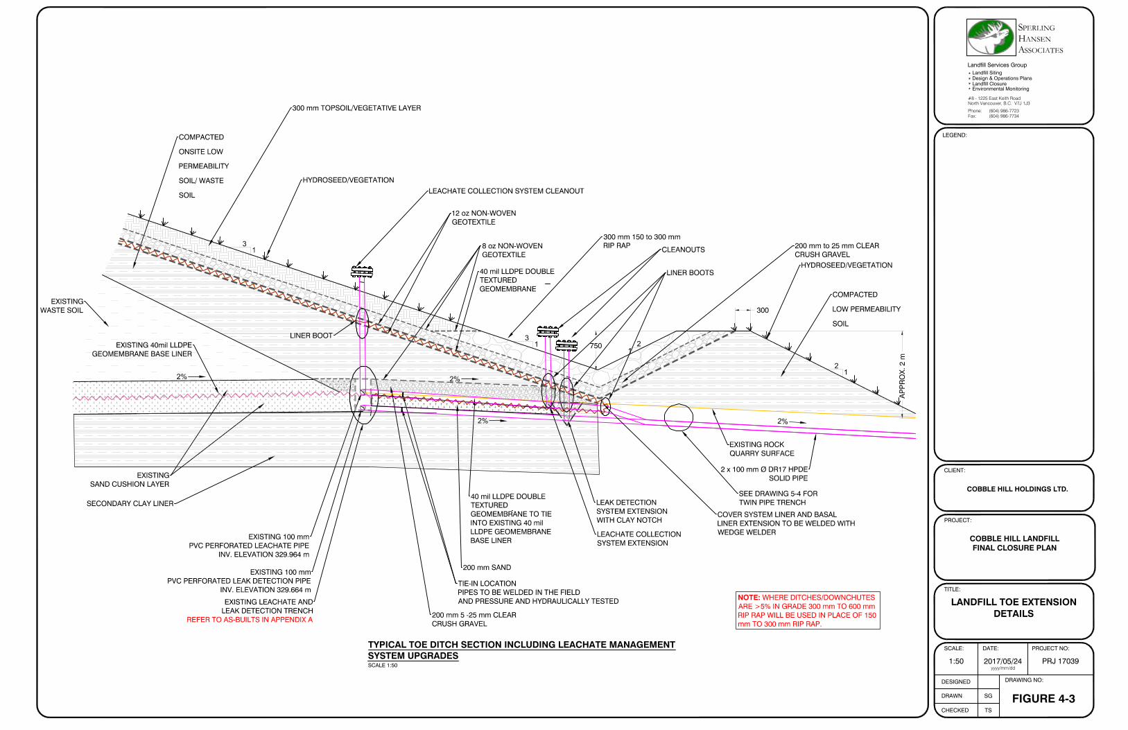
2
1
EXISTINGSAND CUSHION LAYER
750
COMPACTED
ONSITE LOW
PERMEABILITY
SOIL/ WASTE
SOIL
EXISTINGWASTE SOIL
EXISTING 40mil LLDPEGEOMEMBRANE BASE LINER
300 mm TOPSOIL/VEGETATIVE LAYER
HYDROSEED/VEGETATION
300 mm 150 to 300 mmRIP RAP
2
1
3
1
HYDROSEED/VEGETATION
COMPACTED
LOW PERMEABILITY
SOIL
EXISTING ROCKQUARRY SURFACE
300
NOTE: WHERE DITCHES/DOWNCHUTESARE >5% IN GRADE 300 mm TO 600 mmRIP RAP WILL BE USED IN PLACE OF 150mm TO 300 mm RIP RAP.
8 oz NON-WOVENGEOTEXTILE
EXISTING 100 mmPVC PERFORATED LEACHATE PIPE
INV. ELEVATION 329.964 m
2 x 100 mm Ø DR17 HPDESOLID PIPE
SEE DRAWING 5-4 FORTWIN PIPE TRENCH
TIE-IN LOCATIONPIPES TO BE WELDED IN THE FIELDAND PRESSURE AND HYDRAULICALLY TESTED
EXISTING 100 mmPVC PERFORATED LEAK DETECTION PIPE
INV. ELEVATION 329.664 mEXISTING LEACHATE AND
LEAK DETECTION TRENCHREFER TO AS-BUILTS IN APPENDIX A
3
1
200 mm to 25 mm CLEARCRUSH GRAVEL
12 oz NON-WOVENGEOTEXTILE
40 mil LLDPE DOUBLETEXTUREDGEOMEMBRANE
40 mil LLDPE DOUBLETEXTUREDGEOMEMBRANE TO TIEINTO EXISTING 40 milLLDPE GEOMEMBRANEBASE LINER
AP
PR
OX
. 2 m
COVER SYSTEM LINER AND BASALLINER EXTENSION TO BE WELDED WITHWEDGE WELDER
200 mm SAND
LEACHATE COLLECTION SYSTEM CLEANOUT
LINER BOOT
2%
2%
2%
2%
CLEANOUTS
SECONDARY CLAY LINER
LINER BOOTS
LEAK DETECTIONSYSTEM EXTENSIONWITH CLAY NOTCH
LEACHATE COLLECTIONSYSTEM EXTENSION
200 mm 5 -25 mm CLEARCRUSH GRAVEL
LEGEND:
CLIENT:
PROJECT:
TITLE:
SCALE:
DESIGNED
DRAWN
CHECKED
DRAWING NO:
SG
TS
DATE: PROJECT NO:
FIGURE 4-3
COBBLE HILL LANDFILLFINAL CLOSURE PLAN
COBBLE HILL HOLDINGS LTD.
LANDFILL TOE EXTENSIONDETAILS
1:50 2017/05/24 PRJ 17039yyyy/mm/dd
(604) 986-7734(604) 986-7723
North Vancouver, B.C. V7J 1J3#8 - 1225 East Keith Road
Environmental Monitoring
Design & Operations Plans
Landfill Services Group
Fax:Phone:
Landfill Closure
Landfill Siting
SSOCIATES
S PERLING ANSENHA
TYPICAL TOE DITCH SECTION INCLUDING LEACHATE MANAGEMENTSYSTEM UPGRADESSCALE 1:50

Cobble Hill Holdings Ltd. Cobble Hill Landfill 5-1 SPERLING
Final Closure Plan HANSEN PRJ17039 FINAL REPORT ASSOCIATES
5. LEACHATE MANAGEMENT
5.1 Introduction
In this chapter, the leachate management strategy will be outlined. The objective of this chapter is to provide a detailed guide for construction of an effective collection and storage system to ensure minimal risk to the receiving environment upon closure of the CHHL. Additionally, comments and concerns from Ministry of Environment will be outlined and addressed. To our knowledge, the following list of concerns have been reviewed and addressed:
Leachate generation potential including projected quantities and quality
Landfill Liner Strategy – outlined in Chapter 3
Leachate Collection System – outlined in Chapter 3
Leachate Storage and Transportation Planning
Tracking of Leachate Generation and Quality Post Closure
5.2 Leachate Management Strategy
The current definition of contact water at the Cobble Hill Site, as per WSP’s Review of Contact and Non-Contact Water Management Systems, includes: leachate from the PEA; run-off from the PEA; drainage from the SMA; drainage from the vehicle wheel wash area and backwash from the contact water treatment system.
The wheel wash facility has been decommissioned since cancellation of the waste discharge permit at the site. Clean water runoff from the PEA will be handled in the settling pond, as outlined in Chapter 6. As discussed in Chapter 3, Soil Relocation and Encapsulation, following relocation of soil from the SMA to the PEA, the SMA will be decontaminated and decommissioned, thus eliminating the area as a source of contact water. Therefore, the main source of contact water (leachate) will be the PEA.
The primary strategy for minimizing generation of contact water at the site is to close the PEA with a final cover system. Currently, the PEA has been capped with 40mil smooth LLDPE geomembrane since the Fall of 2016. This has already minimized leachate generation as a result of precipitation and rainwater infiltration. In addition, SHA recommends the following strategies for managing leachate:
- During soil relocation and landfilling operations, the use of poly tarps and temporary covers will aid in minimizing clean water contact with contaminated soil. All closure construction works should be completed during dry weather to ensure no additional precipitation is introduced into the PEA.

Cobble Hill Holdings Ltd. Cobble Hill Landfill 5-2 SPERLING
Final Closure Plan HANSEN PRJ17039 FINAL REPORT ASSOCIATES
- Clean run-on from above the PEA should continue to be managed by way of the existing run-on diversion ditching around the perimeter of the PEA and directed offsite or to the existing settling pond in the northwest corner of the site.
- Clean run-on originating from areas outside the quarry footprint should be diverted into natural water courses around the quarry perimeter.
SHA has sized and designed a management system in which generated leachate from within the PEA and leak detection system is conveyed to a double lined storage facility approximately 20m north of the PEA toe, as outlined in Figure 5-1. As the old facility is within the required landfill toe pushout area, construction of the new leachate storage system must precede the regrading and closure of the PEA. The existing contact water treatment system and pond will be decommissioned once the new leachate storage facility is constructed.
Future generated leachate stored in the above-mentioned storage facility will be removed from the primary tank using a vac-truck, and transported offsite to an approved liquid waste acceptance facility.
Since capping the PEA in Fall of 2016, contact water generation at the site has significantly decreased from approximately 1,000-1,500 gallons per day when un-capped to 200 gallons per day in February 2017 and an estimated 126 (0.5m3) gallons per day in May 2017. The 126 gallons per day estimate projects out to 183 m3/year.
5.3 Leachate Generation
The leachate generation estimation was performed using the Hydrologic Evaluation of Landfill Performance (HELP) model. HELP is a quasi-two-dimensional hydrologic model of water movement across, into, through and out of landfills. The model accepts weather, soil and design data and uses solution techniques that account for the effect of surface storage, snowmelt, runoff, infiltration, evapotranspiration, vegetation growth, soil moisture storage, lateral subsurface drainage, leachate recirculation, unsaturated vertical drainage, and leakage through liners. HELP modelling of leachate production with the recommended cover system, documented in Chapter 4, forecasts an average annual leachate production rate of 4.24 mm/year on the crest area and 0.26 mm/year on the side slope area, translating to leachate production rates of 42.4 m3/year and 2.6 m3/year for the approximate 1.0 Ha (8,000m2) site, respectively, will be produced after closure. This is about 10 times less than the amount of leachate currently being captured, indicating that most of the contact water is being generated from consolidation of the soils within the PEA. Based on a 200-year wet winter weather forecast with monthly rainfall intensity of 1.5 times the average and including snow melt and multi-day precipitation, an annual leachate production rate on the crest area of 5.34 mm/year and the slope area of 0.356 mm/year or 53.4 m3/year and 3.56 m3/year for the 1 Ha site, respectively, is predicted as a worst-case leachate generation forecast after closure.
Cobble Hill Holdings Ltd. Cobble Hill Landfill 5-3 SPERLING
Final Closure Plan HANSEN PRJ17039 FINAL REPORT ASSOCIATES
SHA expects that over time, leachate production will decline as the soil consolidation process is completed. Also, a thorough review and inspection program will be undertaken of the existing crest area 40mil LLDPE geomembrane during closure construction works to ensure that all seams, boots and minor holes identified during the last inspection have been properly sealed up. Overall, we anticipate that leachate currently being generated at approximately 0.5 m3/day should reduce to approximately 0.16 m3/day or 58 m3/year, post closure.
5.4 Leachate Quality
SHA reviewed leachate (aka contact water) quality data collected in 2015, 2016 and 2017 from the Containment Pond and the water treatment system at CHHL. Parameters that exceeded the B.C. aquatic life standards (BCAWWQG) from time to time included colour, total suspended solids, turbidity, sulfate, arsenic, copper, iron, pyroxene and benzo (a) pyroxene. The same parameters are often elevated in municipal leachate and in run-off from disturbed areas. As the amount of leachate generated is small, it is not practical to treat leachate on site. Instead, the leachate will be periodically collected and hauled off-site to a waste water treatment facility. Collected and stored leachate volumes will be tracked and noted during transportation activities off site to an approved and regulated liquid disposal facility.
5.5 Leachate Collection and Management
The existing PEA has been constructed to effectively collect leachate via the sand drainage layers on top of 40mil LLDPE geomembrane basal liner graded at approximately 2% from south to north with 100mm perforated PVC collection piping along the downgradient toe (north side) of the cell. The PEA is also equipped with a leachate leak detection system below the basal liner geomembrane. This system is composed of a sand drainage layer overtop of a compacted clay liner graded at approximately 2% from south to north with 100mm perforated PVC collection piping along the downgradient toe (north side) of the cell. Both the existing leachate collection and leak detection systems are further detailed in the as-built documents included in Appendix B. As outlined previously in Chapter 4 Final Closure Design, the toe of the closed PEA will be extended both north and east to allow for a final 3H:1V slope to ensure stability of the final cover system. Due to the landfill toe extension, the existing leachate tank and leak detection tank storage area will need to be relocated further towards the north to ensure sufficient room for closure construction works. Additionally, as outlined in Chapter 4, SHA is recommending that along with the landfill toe extension, a new leachate and leak detection system be included in the final closure works.

Cobble Hill Holdings Ltd. Cobble Hill Landfill 5-4 SPERLING
Final Closure Plan HANSEN PRJ17039 FINAL REPORT ASSOCIATES
Figure 5-2 and 5-3 outline SHA’s design concept for leachate conveyance and temporary onsite storage. As outlined, during closure construction, the first work task will be to tie-in to the existing leachate and leak detection systems current discharge point and extend conveyance piping further north away from the landfill. This will include 100mm HDPE piping installed in a subsurface trench to the new tank location. SHA envisions the leak detection and leachate pipe extension should be installed in a common trench at 2% grade with proper granular backfill at minimum depth of 500mm below existing grade, as seen in Figure 5-4.
To maintain the existing leachate collection piping and proposed conveyance piping, cleanouts will be added at the ends of each collector and mid point, resulting in pipe runs of approximately 50 m. A cleanout should be installed at the existing leachate discharge pipe location (tie-in to conveyance piping) and daylighted through the final cover system on the north slope to allow for flushing of the perforated 100mm PVC collection piping. A second cleanout should be installed near the leachate storage facility to allow flushing of the 100mm solid HDPE conveyance piping. Additionally, cleanouts should be included in similar locations for the newly proposed leachate and leak detection systems at the toe of the 3H:1V slope. The leachate cleanouts are outlined on Figures 5-2 and 5-3.
Leachate generated from above the liner and potential leak detection leachate will be kept separate. Below is a description of the recommended leachate storage requirements:
Leak Detection Storage Tank - 2,500 gallon HDPE Plastic Tank excavated into existing ground to ensure gravity drainage from the PEA and to provide full use / storage capabilities of the tank volume.
Leachate Storage Tank – 10,000 gallon HDPE Plastic Tank excavated into existing ground to ensure gravity drainage from the PEA and to provide full use / storage capabilities of the tank volume.
To ensure secondary containment in the event of a leak from the above-mentioned tanks, the subsurface tanks will be held within a lined lock block well, large enough to hold both tanks. It is recommended that the secondary liner be at minimum a 40mil geomembrane accompanied by an underlaying cushion layer (heavy weight non-woven geotextile) and 300 mm of sand or fine gravel cushion protection under the tanks. The secondary containment liner system should be fastened to the top of the lock block walls with a steel bar, Hilti bolted to the concrete blocks. To allow for leak monitoring, a roof structure will be built over the storage tank facility to keep precipitation out. This will mean, that any liquid observed on the secondary liner system will have originated from a leak or from condensation on the plastic liner. It will be possible to test the water for conductivity to determine if it represents leakage of clean condensation. Testing can be conducted during leachate removal / transportation and monitoring events.
The above-mentioned leachate storage and containment system may be altered during closure construction if designed and approved by a qualified professional.
Cobble Hill Holdings Ltd. Cobble Hill Landfill 5-5 SPERLING
Final Closure Plan HANSEN PRJ17039 FINAL REPORT ASSOCIATES
5.6 Leachate Monitoring
In order to track the on-site water balance, both leachate collection system and leak detection system will be monitored for actual production at the proposed leachate storage facility. On a monthly basis or during pumping and transportation events, prior to pumping and transporting off site, leachate volumes will be measured and tracked. This will be double checked against leachate transport and disposal will be invoices which will also record the volumes of leachate based on $/gal transported and disposed of. Over time, as leachate generation is reduced, monitoring events may be spread out over a longer period of time. Initially, monthly visual inspections are recommended. Additionally, it is recommended that leachate be sampled and analyzed from the storage facility prior to transportation events.
5.7 Leachate Transportation Off Site
SHA’s understanding is leachate is currently being generated at a rate of approximately 126 gal/day (approximately 0.5 m3 per day). As outlined above, SHA recommends a 10,000 gallon (or 37.8 cubic metre) double lined storage facility is installed in the ground approximately 20 m north of the landfill toe on the north side. Leachate will be gravity fed from the landfill to the tank. Post closure, leachate generation will drastically be reduced, as outlined above. Although not right away, leachate generation should reduce to approximately 5m3/month. Based on post closure generation projections and the proposed leachate tank volume, the tank should be pumped, transported and disposed of every 6 months. It is SHA’s recommendation that initially, until leachate flows are reduced, the storage tanks be monitored monthly.
Leachate stored in the tanks will be removed via a vac-truck (pumped truck) and transported off site to a regulated liquid waste facility for disposal.
SHA estimates that once closure is completed, the primary and secondary liner system, along with evapotranspiration from established vegetation will reduce the frequency of leachate removal activities.
5.8 Clean Run-off Treatment Strategy
Clean run-off from closed cells as well as run-off from the rock quarry will be directed to the clean water settlement pond. There, any suspended sediments will be reduced through retention. With regards to potential upward groundwater flow; it is recognized that the potential for groundwater seepage to be impacted by the overlying contaminated soil is very remote. The rate of seepage into the blanket from the rock below is not sufficient to cause any appreciable groundwater mounding within the drainage blanket, such that it may contact the encapsulated soil cells above.

Cobble Hill Holdings Ltd. Cobble Hill Landfill 5-6 SPERLING
Final Closure Plan HANSEN PRJ17039 FINAL REPORT ASSOCIATES
The clay base liner also immediately overlies the Seepage Blanket. This limits the potential for impacts to the Seepage Blanket water quality from overlying permanent encapsulation cells. Groundwater seepage from beneath the basal liner system will be allowed to flow naturally beneath the base of the quarry and make its way to the existing onsite surface water settling pond. The PEA will be fully closed off to the environment rendering all precipitation, run-on, run-off and any potential groundwater seepage below the PEA as clean water. These clean flows will all report to the settling pond for retention and discharge. Sampling and monitoring of settling pond discharge is outlined further on in Chapter 9.

3
3
0
3
3
0
EXISTING LEACHATE DETECTION TANK
TO BE REMOVED
3
4
0
3
3
5
3
3
0
3
3
1
3
3
5
LEACHATE AND LEAK
DETECTION TIE-IN LOCATION
EXISTING LEAK
DETECTION TANK
TO BE REMOVED
2-100 mm DR17 HDPE SOLID PIPE IN
TWIN TRENCH. SEE FIGURE 5-4 FOR
DETAIL.
CLEAN-OUT
CONCRETE NO POST
BARRIERS
2,500 GALLON LEAK DETECTION
STORAGE TANK
INV.328.5 m
5-35-4
10,000 GALLON LEACHATE
STORAGE TANK
INV. 328.5 m
EXISTING PERMANENT
ENCAPSULATION CELL -
EXTENT
ROOF STRUCTURE BUILT ON LOCK
BLOCK CONTAINMENT
PRIMARY CONTAINMENT
LINED LOCK BLOCK SUMP
(SECONDARY CONTAINMENT MEASURE)
BASE LINER EXTENSION
EXISTING LEACHATE
COLLECTOR AND LEAK
DETECTION PIPE
PROPOSED LEACHATE
COLLECTOR AND LEAK
DETECTION PIPE
LEGEND:
CLIENT:
PROJECT:
TITLE:
SCALE:
DESIGNED
DRAWN
CHECKED
DRAWING NO:
SG
TS
DATE: PROJECT NO:
FIGURE 5-1
COBBLE HILL LANDFILL FINALCLOSURE PLAN
COBBLE HILL HOLDINGS LTD.
LEACHATE MANAGEMENTSYSTEM UPGRADES
1:250 2017/05/24 PRJ 17039yyyy/mm/dd
(604) 986-7734(604) 986-7723
North Vancouver, B.C. V7J 1J3#8 - 1225 East Keith Road
Environmental Monitoring
Design & Operations Plans
Landfill Services Group
Fax:Phone:
Landfill Closure
Landfill Siting
SSOCIATES
S PERLING ANSENHA
5m EXISTING CONTOUR
1m EXISTING CONTOUR
5m AS-BUILT CONTOUR
1m AS-BUILT CONTOUR
ROAD
SURFACE WATER DITCH
PROPERTY LINES
N
CREEK
LANDFILL LINER EXTENTS
PROPOSED SOLIDLEACHATE COLLECTORPIPE
PROPOSED PERFORATEDLEACHATECOLLECTOR/LEACKDETECTION PIPE
EXISTING PERFORATEDLEACHATECOLLECTOR/LEAKDETECTION PIPE
PROPOSED CLEAN-OUT

2
1
EXISTINGSAND CUSHION LAYER
750
COMPACTED
ONSITE LOW
PERMEABILITY
SOIL/ WASTE
SOIL
EXISTINGWASTE SOIL
EXISTING 40mil LLDPEGEOMEMBRANE BASE LINER
300 mm TOPSOIL/VEGETATIVE LAYER
HYDROSEED/VEGETATION
300 mm 150 to 300 mmRIP RAP
2
1
3
1
HYDROSEED/VEGETATION
COMPACTED
LOW PERMEABILITY
SOIL
EXISTING ROCKQUARRY SURFACE
300
NOTE: WHERE DITCHES/DOWNCHUTESARE >5% IN GRADE 300 mm TO 600 mmRIP RAP WILL BE USED IN PLACE OF 150mm TO 300 mm RIP RAP.
8 oz NON-WOVENGEOTEXTILE
EXISTING 100 mmPVC PERFORATED LEACHATE PIPE
INV. ELEVATION 329.964 m
CONTINUES
ON FIGURE 5-32 x 100 mm Ø DR17 HPDESOLID PIPESEE DRAWING 5-4 FORTWIN PIPE TRENCH
TIE-IN LOCATIONPIPES TO BE WELDED IN THE FIELDAND PRESSURE AND HYDRAULICALLY TESTED
EXISTING 100 mmPVC PERFORATED LEAK DETECTION PIPE
INV. ELEVATION 329.664 mEXISTING LEACHATE AND
LEAK DETECTION TRENCHREFER TO AS-BUILTS IN APPENDIX A
3
1
200 mm to 25 mm CLEARCRUSH GRAVEL
12 oz NON-WOVENGEOTEXTILE
40 mil LLDPE DOUBLETEXTUREDGEOMEMBRANE
40 mil LLDPE DOUBLETEXTUREDGEOMEMBRANE TO TIEINTO EXISTING 40 milLLDPE GEOMEMBRANEBASE LINER
AP
PR
OX
. 2 m
COVER SYSTEM LINER AND BASALLINER EXTENSION TO BE WELDED WITHWEDGE WELDER
200 mm SAND
LEACHATE COLLECTION SYSTEM CLEANOUT
LINER BOOT
2%
2%
2%
2%
CLEANOUTS
SECONDARY CLAY LINER
LINER BOOTS
LEAK DETECTIONSYSTEM EXTENSIONWITH CLAY NOTCH
LEACHATE COLLECTIONSYSTEM EXTENSION
200 mm 5 -25 mm CLEARCRUSH GRAVEL
LEGEND:
CLIENT:
PROJECT:
TITLE:
SCALE:
DESIGNED
DRAWN
CHECKED
DRAWING NO:
SG/MG
TS
DATE: PROJECT NO:
FIGURE 5-2
COBBLE HILL LANDFILLFINAL CLOSURE PLAN
COBBLE HILL HOLDINGS LTD.
LEACHATE MANAGEMENTUPGRADES
1:50 2017/05/24 PRJ 17039yyyy/mm/dd
(604) 986-7734(604) 986-7723
North Vancouver, B.C. V7J 1J3#8 - 1225 East Keith Road
Environmental Monitoring
Design & Operations Plans
Landfill Services Group
Fax:Phone:
Landfill Closure
Landfill Siting
SSOCIATES
S PERLING ANSENHA
TYPICAL TOE DITCH SECTION INCLUDING LEACHATE MANAGEMENTSYSTEM UPGRADESSCALE 1:50

CONTINUES
ON FIGURE 5-2100 mm Ø DR17 HPDESOLID PIPE
SEE FIGURE 5-4 FORTWIN PIPE TRENCH
2,500 GALLON (9.46 m3)
LEAK DETECTION TANK
(NTS)
100 mm DR17 HDPE PIPEINV. ELEVATION 328.5 m
+ 329.25 m EL.
CLEAN-OUT
LOCK BLOCK
ACCESSTO TANK
ROOF STRUCTURE
SECONDARYCONTAINMENT LINER
QUARRY FILL
CONTINUES
ON FIGURE 5-2100 mm Ø DR17 HPDESOLID PIPE
SEE FIGURE 5-4 FORTWIN PIPE TRENCH
10,000 GALLON (37.85 m3)
LEACHATE HOLDING TANK
(NTS)100 mm DR17 HDPE PIPEINV. ELEVATION 328.5 m
+ 329.25 m EL.
ROOF STRUCTURE
ACCESS TOTANKCLEAN-OUT
SECONDARYCONTAINMENT LINER
LOCK BLOCK
QUARRY FILL
LEGEND:
CLIENT:
PROJECT:
TITLE:
SCALE:
DESIGNED
DRAWN
CHECKED
DRAWING NO:
SG/MG
TS
DATE: PROJECT NO:
FIGURE 5-3
COBBLE HILL LANDFILLFINAL CLOSURE PLAN
COBBLE HILL HOLDINGS LTD.
LEACHATE MANAGEMENTSYSTEM UPGRADE DETAILS
ASSHOWN 2017/05/24 PRJ 17039
yyyy/mm/dd
(604) 986-7734(604) 986-7723
North Vancouver, B.C. V7J 1J3#8 - 1225 East Keith Road
Environmental Monitoring
Design & Operations Plans
Landfill Services Group
Fax:Phone:
Landfill Closure
Landfill Siting
SSOCIATES
S PERLING ANSENHA
CROSS SECTION OF LEAK DETECTION STORAGE TANKSCALE NTS
CROSS SECTION OF LEACHATE STORAGE TANKSCALE NTS
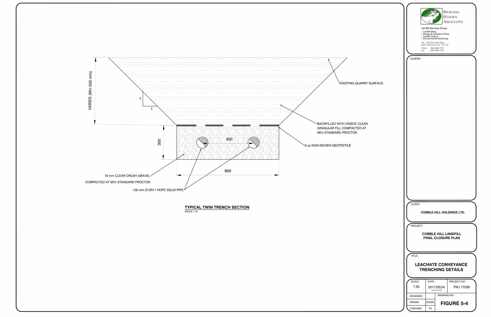
100 mm Ø DR17 HDPE SOLID PIPE
EXISTING QUARRY SURFACE
8 oz NON-WOVEN GEOTEXTILE
19 mm CLEAR CRUSH GRAVEL
COMPACTED AT 95% STANDARD PROCTOR
300
900
450
VA
RIE
S (
Min
500
mm
)
BACKFILLED WITH ONSITE CLEANGRANULAR FILL COMPACTED AT95% STANDARD PROCTOR
1
1
LEGEND:
CLIENT:
PROJECT:
TITLE:
SCALE:
DESIGNED
DRAWN
CHECKED
DRAWING NO:
SG/MG
TS
DATE: PROJECT NO:
FIGURE 5-4
COBBLE HILL LANDFILLFINAL CLOSURE PLAN
COBBLE HILL HOLDINGS LTD.
LEACHATE CONVEYANCETRENCHING DETAILS
1:25 2017/05/24 PRJ 17039yyyy/mm/dd
(604) 986-7734(604) 986-7723
North Vancouver, B.C. V7J 1J3#8 - 1225 East Keith Road
Environmental Monitoring
Design & Operations Plans
Landfill Services Group
Fax:Phone:
Landfill Closure
Landfill Siting
SSOCIATES
S PERLING ANSENHA
TYPICAL TWIN TRENCH SECTIONSCALE 1:10
Cobble Hill Holdings Ltd. Cobble Hill Landfill 6-1 SPERLING
Final Closure Plan HANSEN
PRJ17039 FINAL REPORT ASSOCIATES
6. SURFACE WATER MANAGEMENT The primary objectives of the surface water management plan for the CHHL are to:
Keep clean water clean, Prevent erosion of the final cover system, Minimize percolation through the top surface of the landfill cover system; Prevent ponding of surface water on the cover system, Manage suspended sediments, Minimize leachate production, Control surface water in a manner compatible with the proposed end-uses.
This chapter reviews the background information on existing conditions and provides recommendations on run-on diversion, ditch sizing, storm water control and runoff controls during landfill closure development and post closure period. In order to determine the sizing of the toe/road swales/ditches, peak flows were determined using the Rational Method, which is commonly used to determine the peak flow runoff rates in small watersheds. The rationale for the method is that steady uniform rainfall intensity will cause runoff to reach its maximum rate when all parts of a watershed are contributing to the point of outflow. This is dependent on the time of concentration, which is taken as the time for water to flow to the outflow from the most remote point of the watershed. Along with the rainfall intensity and drainage area, which are relatively straightforward to determine, the peak flow is dependent on the runoff coefficient. The runoff coefficient is dependent on the final cover design. It is primarily influenced by topography, vegetation, the seasons and the subsurface material type. The method and coefficients for the analysis were obtained from the BC Agricultural Drainage Manual (1997). This method allows for variations of the material types, the vegetation types and the topography (slope) conditions. In order to satisfy the requirements outlined in the amended Spill Prevention Order MO:1701, stormwater works were modelled using a 1 in 200-year design storm event with allowances for snowmelt and multi-day precipitation. To do so, four scenarios were calculated, as seen in Table 6-1 below.
Table 6-1: Rainfall Intensity Calculations. Scenario Description Intensity Reference
mm/day mm/hr
Scenario 1 200 years Rainfall 168.7 7.0 WSP Addenda Scenario 2 Multi Day Event 55.08 2.29 Environment Canada Scenario 3 Peak Daily Plus Snow Melt 223.0 9.3 Environment Canada Scenario 4 5 minute Tc 1056.0 44.0 IDF extrapolation

Cobble Hill Holdings Ltd. Cobble Hill Landfill 6-2 SPERLING
Final Closure Plan HANSEN
PRJ17039 FINAL REPORT ASSOCIATES
Scenario 1: The 200 year 24-hour rainfall amount estimate outlined in the WSP Addendum Review of Contact and Non-Contact Water Management Systems is 168.7mm, based on an extrapolation from the IDF curve. Scenario 2: SHA retrieved Daily climate data for the Lake Cowichan weather station for the year with the peak amount of precipitation recorded (1997). Multi-Day rainfall events were tabulated through processing the data and summing the total precipitation received over consecutive days. A rain event was considered to start at the first day with precipitation recorded and end at the last consecutive day with precipitation recorded. The maximum multi-day rain event occurred between March 16th to March 20th 1997 where 275.4 mm of total precipitation was recovered over 5 days, resulting in a daily intensity of 55.08 mm/day. Scenario 3: The maximum total daily precipitation observed in 1997 was 136.8mm on March 17th 1997. The peak snowfall recorded in 1997 was 17.4cm on January 1st. To account for snowmelt, SHA calculated the amount of snowmelt that would occur from 5 days of peak snowfall (17.4cm). A scenario was created in which snowmelt from 5 days of peak snowfall occurred at the same day as peak rainfall (136.8mm). This provided a daily maximum of 223 mm of precipitation/snowmelt on this day. This also correlates well with a 1 in 200 year 24 hour event and 5 cm of snow melt, which is a reasonable worst case scenario as it is very unlikely that a major snow melt event would occur concurrently with a 1 in 200 year rainfall event. Scenario 4: SHA extrapolated a rainfall event from the IDF curve, for a time of concentration of 5 minutes. This event provided a rainfall intensity of 44mm per hour, translating into 1056 mm per day. As Scenario 4 resulted in the maximum daily precipitation and maximum rainfall intensity, this value was used to size the ditches. This rainfall intensity is greater than 600% that of the 200 year storm intensity. The calculated flow rate for the above mentioned extreme event, using the Rational Method, is 0.09 m3/s. SHA’s toe ditch design has capacity for 4.91 m3/s of flow; the Crest ditch has 3.84m3/s capacity; and the downchute has 13.13m3/s capacity. Therefore, all stormwater ditches and downchutes are designed to accommodate for a 1 in 200-year rainfall event, with allowances for snowmelt and multi-day precipitation.
6.1 Drainage Plan for the Cobble Hill Holdings Landfill
The key goal of the surface water management plan for the CHL is to keep clean water clean and minimize leachate production by diverting onsite clean surface water away from potential contact with the landfill cell. The goal is to direct clean water through ditching and overland flow to the Western Settlement Pond prior to discharging offsite to an ephemeral tributary of Shawnigan Creek.

Cobble Hill Holdings Ltd. Cobble Hill Landfill 6-3 SPERLING
Final Closure Plan HANSEN
PRJ17039 FINAL REPORT ASSOCIATES
6.1.1 Run-On Diversion
Based on the topography surrounding the site, all surface water which accumulates due to precipitation and that does not fall on the landfill portion of the site will be directed to Shawnigan Creek to the east and south and to the ephemeral tributary of Shawinigan Creek to the north.
6.1.2 Storm Water Routing
Upon final closure of the CHL, diversion of clean run-off from the geomembrane cap will be required. Figure 6-1 shows the location and orientation of the ditches and downchutes for the closure of the CHHL. It is proposed that the crest of the landfill be graded at 8-10% for drainage purposes, as per the B.C. Landfill Criteria. Surface water run-off from the crest will drain at a minimum grade of 8% through ditches and downchutes. Run-off draining to the north and west will be collected at the toe of the landfill and directed towards the Western Settlement Pond through the clean surface water conveyance ditch seen in Figure 6-1.
6.1.3 Toe/ Road Ditches
Control of erosion in the ditch is a key consideration. The top layer of the ditch will consist of 300 mm thick layer of rip rap or an erosion control blanket. Underlying the rip rap material will be a heavy weight geotextile overlying the compacted low permeability material as shown in Figure 6-2. It may be possible to replace the rip rap with a less expensive erosion control mat, as shown in Photo 6-1, when ditch grades are less than 5% grade. SHA recommends ditches with a triangular cross section, 0.75m depth and 2H:1V side slopes lined with a 300mm layer of 150mm to 300mm Rip Rap. The sizing of this ditch exceeds the requirements for a 1 in 200-year storm event including snowmelt and multi-day precipitation. Analysis of ditches can be revisited during detailed design.
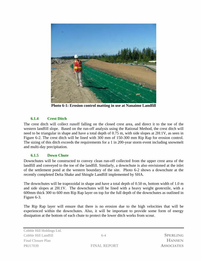
Cobble Hill Holdings Ltd. Cobble Hill Landfill 6-4 SPERLING
Final Closure Plan HANSEN
PRJ17039 FINAL REPORT ASSOCIATES
Photo 6-1: Erosion control matting in use at Nanaimo Landfill
6.1.4 Crest Ditch
The crest ditch will collect runoff falling on the closed crest area, and direct it to the toe of the western landfill slope. Based on the run-off analysis using the Rational Method, the crest ditch will need to be triangular in shape and have a total depth of 0.75 m, with side slopes at 2H:1V, as seen in Figure 6-2. The crest ditch will be lined with 300 mm of 150-300 mm Rip Rap for erosion control. The sizing of this ditch exceeds the requirements for a 1 in 200-year storm event including snowmelt and multi-day precipitation.
6.1.5 Down Chute
Downchutes will be constructed to convey clean run-off collected from the upper crest area of the landfill and conveyed to the toe of the landfill. Similarly, a downchute is also envisioned at the inlet of the settlement pond at the western boundary of the site. Photo 6-2 shows a downchute at the recently completed Delta Shake and Shingle Landfill implemented by SHA. The downchutes will be trapezoidal in shape and have a total depth of 0.50 m, bottom width of 1.0 m and side slopes at 2H:1V. The downchutes will be lined with a heavy weight geotextile, with a 600mm thick 300 to 600 mm Rip Rap layer on top for the full depth of the downchutes as outlined in Figure 6-3. The Rip Rap layer will ensure that there is no erosion due to the high velocities that will be experienced within the downchutes. Also, it will be important to provide some form of energy dissipation at the bottom of each chute to protect the lower ditch works from scour.
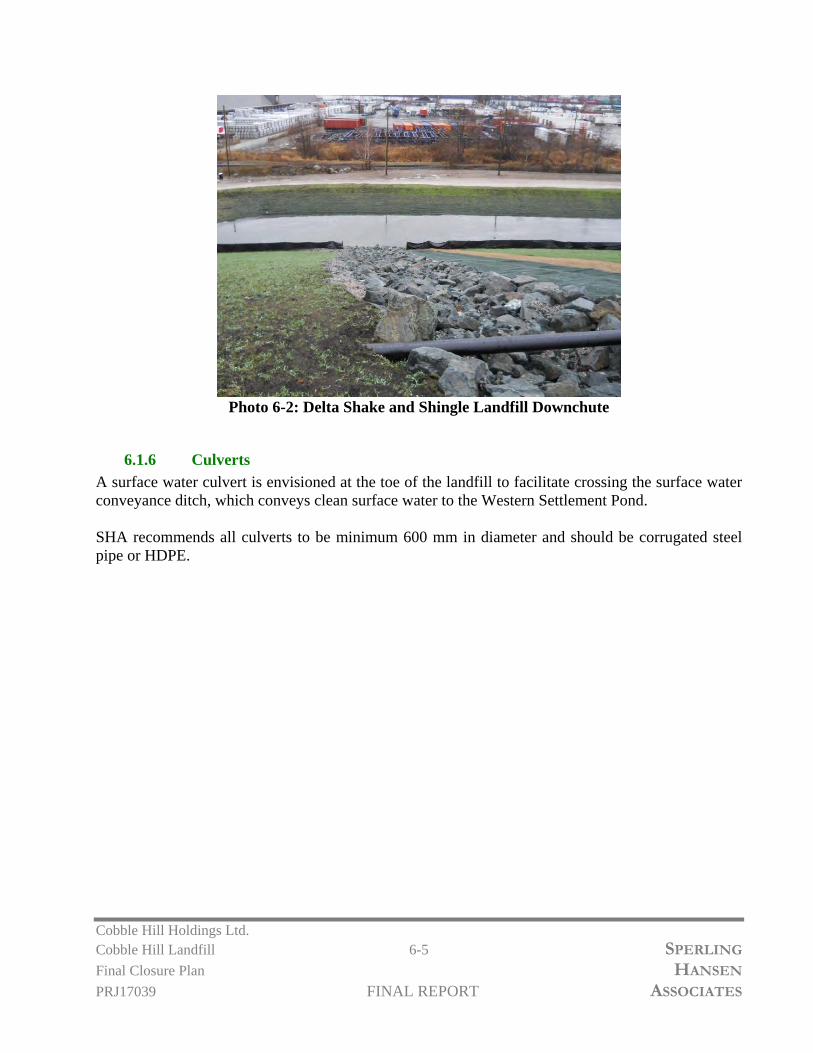
Cobble Hill Holdings Ltd. Cobble Hill Landfill 6-5 SPERLING
Final Closure Plan HANSEN
PRJ17039 FINAL REPORT ASSOCIATES
Photo 6-2: Delta Shake and Shingle Landfill Downchute
6.1.6 Culverts
A surface water culvert is envisioned at the toe of the landfill to facilitate crossing the surface water conveyance ditch, which conveys clean surface water to the Western Settlement Pond. SHA recommends all culverts to be minimum 600 mm in diameter and should be corrugated steel pipe or HDPE.

3
2
9
325
3
3
0
3
3
0
3
4
0
335
330
3
3
1
3
3
0
3
4
1
3
3
9
325
3
2
4
3
4
0
3
4
0
3
3
5
3
4
5
3
4
6
3
4
5
O
V
E
R
H
E
A
D
H
Y
D
R
O
L
I
N
E
O
V
E
R
H
E
A
D
H
Y
D
R
O
L
IN
E
455,100
455,200
5,377,600
5,377,700
5,377,800
345
3
5
0
3
4
2
3
4
3
3
4
0
3
3
8
3
3
7
3
3
6
3
3
5
3
4
0
3
4
0
3
4
0
3
3
5
3
3
5
3
3
0
3
3
5
3
3
1
3
3
2
3
3
1
3
3
1
3
3
2
3
2
9
3
3
0
3
3
0
RUN-ON DIVERSION
DITCH
TOE SURFACE WATER DITCH
P
R
O
P
E
R
T
Y
L
IN
E
S
E
T
T
L
IN
G
P
O
N
D
SETTLING POND
P
E
R
M
A
N
E
N
T
E
N
C
A
P
S
U
L
A
T
I
O
N
C
E
L
L
TOE SURFACE WATER
DITCH
3
H
:
1
V
3
H
:
1
V
10H
:1V
CREST SURFACE WATER
DITCH
SURFACE WATER CONVEYANCE DITCH
LEGEND:
CLIENT:
PROJECT:
TITLE:
SCALE:
DESIGNED
DRAWN
CHECKED
DRAWING NO:
SG
TS
DATE: PROJECT NO:
FIGURE 6-1
COBBLE HILL LANDFILLFINAL CLOSURE PLAN
COBBLE HILL HOLDINGS LTD.
SURFACE WATERMANAGEMENT PLAN
1:750 2017/05/26 PRJ 17039yyyy/mm/dd
(604) 986-7734(604) 986-7723
North Vancouver, B.C. V7J 1J3#8 - 1225 East Keith Road
Environmental Monitoring
Design & Operations Plans
Landfill Services Group
Fax:Phone:
Landfill Closure
Landfill Siting
SSOCIATES
S PERLING ANSENHA
5m EXISTING CONTOUR
1m EXISTING CONTOUR
5m DESIGN CONTOUR
1m DESIGN CONTOUR
ROAD
SURFACE WATER DITCH
PROPERTY LINES
N
CREEK
LANDFILL EXTENTS

2
1
EXISTING SAND CUSHION LAYER
750
MINIMUM 500 mm
LOW PERMEABILITY SOIL
8oz NON-WOVEN GEOTEXTILE
EXISTING WASTE SOIL
EXISTING 40mil LLDPE GEOMEMBRANE LINER200 mm SAND DRAINAGE LAYER
300 mm TOPSOIL/VEGETATIVE LAYER HYDROSEED/VEGETATION
300 mm 150 to 300 mmRIP RAP
200 mm 5 to 25 mmCLEAR CRUSH DRAINROCK
2
1
NOTE: WHERE DITCHES/DOWNCHUTESARE >5% IN GRADE 300 mm TO 600 mmRIP RAP WILL BE USED IN PLACE OF 150mm TO 300 mm RIP RAP.
8 oz NON-WOVENGEOTEXTILE
LEGEND:
CLIENT:
PROJECT:
TITLE:
SCALE:
DESIGNED
DRAWN
CHECKED
DRAWING NO:
SG/MG
TS
DATE: PROJECT NO:
FIGURE 6-2
COBBLE HILL LANDFILLFINAL CLOSURE PLAN
COBBLE HILL HOLDINGS LTD.
TYPICAL CREST DITCHSECTION
1:50 2017/05/24 PRJ 17039yyyy/mm/dd
(604) 986-7734(604) 986-7723
North Vancouver, B.C. V7J 1J3#8 - 1225 East Keith Road
Environmental Monitoring
Design & Operations Plans
Landfill Services Group
Fax:Phone:
Landfill Closure
Landfill Siting
SSOCIATES
S PERLING ANSENHA
TYPICAL CREST DITCH SECTIONSCALE 1:50

2
1
500
1000
COMPACTED ONSITE
LOW PERMEABILITY SOIL
EXISTING WASTE SOIL
12 oz NON-WOVENGEOTEXTILE
300 mmTOPSOIL/VEGETATIVELAYER
HYDROSEED/VEGETATION
300 mm LAYER OF 300 to600 mm RIP RAP
200 mm 5 to 25 mmCLEAR CRUSH
300 300
2
1
2
1
8oz NON-WOVEN GEOTEXTILE
NOTE: WHERE DITCHES/DOWNCHUTESARE >5% IN GRADE 300 mm TO 600 mmRIP RAP WILL BE USED IN PLACE OF 150mm TO 300 mm RIP RAP.
40 mil LLDPE DOUBLE
TEXTURED GEOMEMBRANE
2
1
500
1000
COMPACTED EXCAVATED
MATERIAL FROM DOWNCHUTE EXCAVATION
EXISTING ROCK QUARRY SURFACE
300 mm LAYER OF 300 to600 mm RIP RAP
200 mm COMPACTEDLOW PERMEABILITY SOIL
300 300
2
1
2
1
NOTE: WHERE DITCHES/DOWNCHUTESARE >5% IN GRADE 300 mm TO 600 mmRIP RAP WILL BE USED IN PLACE OF 150mm TO 300 mm RIP RAP.
8oz NON-WOVENGEOTEXTILE
LEGEND:
CLIENT:
PROJECT:
TITLE:
SCALE:
DESIGNED
DRAWN
CHECKED
DRAWING NO:
SG/MG
TS
DATE: PROJECT NO:
FIGURE 6-3
COBBLE HILL LANDFILLFINAL CLOSURE PLAN
COBBLE HILL HOLDINGS LTD.
TYPICAL DOWNCHUTEDETAILS
1:50 2017/05/24 PRJ 17039yyyy/mm/dd
(604) 986-7734(604) 986-7723
North Vancouver, B.C. V7J 1J3#8 - 1225 East Keith Road
Environmental Monitoring
Design & Operations Plans
Landfill Services Group
Fax:Phone:
Landfill Closure
Landfill Siting
SSOCIATES
S PERLING ANSENHA
TYPICAL DOWNCHUTE - WASTE SOIL AREASCALE 1:50
TYPICAL DOWNCHUTE TO SETTLING PONDSCALE 1:50

Cobble Hill Holdings Ltd. Cobble Hill Landfill 7-1 SPERLING Final Closure Plan HANSEN PRJ17039 FINAL REPORT ASSOCIATES
7. GEOTECHNICAL CONSIDERATIONS This section includes an assessment of the adequacy of the existing facility with regard to the stability of the landfill for both static and seismic conditions. The global stability has been assessed for two critical sections and the veneer stability has been assessed for the critical veneer slope. The veneer stability analysis involves shear strength property of each layer in the cover veneer including the geomembrane and geotextile interface for the proposed slope of 3H:1V. 7.1 Steep Slope Remediation and Liner System Upgrades As previously outlined in Chapters 3,4 and 5, SHA is proposing to remove the existing 40mil LLDPE Smooth Geomembrane Liner from the sloped areas of the PEA, to extend the landfill toe and basal liner system on the east and north slopes to 3H:1V by building a soil subgrade wedge and to construct a new geosynthetic cover system which includes the use of 40mil LLDPE Double Textured Geomembrane, gravel drainage layer and updated leachate collection system notched into the clay basal layer. 7.2 Underlying Stratigraphy The ground surface at the site is an expression of an igneous intrusion of very hard granite bedrock through underlying bedrock known as Wark Gneiss. This hard granite rock, as well as the Wark Gneiss, are the source of materials for the quarry. The groundwater flow regime in the vicinity of the site is predominantly via fractured flow within a deep bedrock aquifer. Overburden soils are not thick enough in the region to develop an overburden aquifer. 7.3 Slope Stability Analysis The purpose of this section is to prove that the proposed final design for the site will maintain acceptable factors of safety against failure. Stability of the site was modeled using the program SLIDE 4.0 designed for 2D slope stability analysis for soil and rock slopes.
7.3.1 Slope Stability Model
To verify stability of the proposed regrading, SHA conducted a detailed analysis using computer program SLIDE. The results of SLIDE analysis are found in Appendix C. The slope stability models discussed below have been developed largely from strength parameters that we have used for similar conditions. Two cross-sections were selected through representative sloped areas of the site. The cross sections were developed from the proposed final design contours shown in Figure 7-1. The cross-section locations analyzed are identified in plan view in the figure. The cross sections (A-A’ and B-B’) used in the stability analysis are located in Appendix D Figures D-1 to D-2. These figures show the underlying geology of the landfill, the proposed profile and the material parameters used in the analysis. The analysis was performed using limit equilibrium technique and Bishop Simplified method of analysis. Materials are modeled using a Mohr-Coulomb strength envelope.

Cobble Hill Holdings Ltd. Cobble Hill Landfill 7-2 SPERLING Final Closure Plan HANSEN PRJ17039 FINAL REPORT ASSOCIATES
Failure scenarios were modeled for both static and seismic (earthquake) conditions for the proposed and existing profiles. The following factors of safety (FOS) for slope failure have been adopted as minimum standards:
Static Conditions adjacent to Developed Land and Infrastructure 1.5 Static Conditions adjacent to Undeveloped Land 1.3 Seismic (Earthquake) Loading 1.0
A pseudo-static analysis was performed to determine if the slopes would be stable during an earthquake when subjected to peak ground acceleration expected for the area. The National Building Code of Canada 2012, Volume 2 provides seismic values for a number of locations across Canada. The peak horizontal ground acceleration (PGA) of 0.61 g for the Victoria area was found. This PGA has a probability of exceedance of 2% in 50 years. The PGA acts momentarily in one direction and its use with static material properties may yield very low and incorrect factors of safety. The United States Environmental Protection Agency document “RCRA Subtitle D (258) Seismic Design Guidance for Municipal Waste Landfill Facilities (1995)” recommends using a seismic coefficient ks of 50% of the PGA, in combination with the dynamic shear strength properties of the materials. Therefore, a design PGA of 0.305 g was used in the analysis. A vertical acceleration was also applied to the model and is typically between 60% and 75% of the horizontal acceleration. Therefore, 0.183 g for the vertical acceleration was chosen. A number of assumptions were made in the process of simplifying complex situations in the field to a computer model:
Strength characteristics of the ground materials were generalized; Stabilizing effects of vegetative cover on the side slopes were not included; Ground water levels were assumed to be below the seepage drainage layer at the floor of the
pit, except for perched water levels in the cover system.
7.3.2 Soil Strength Parameters
Table 7-1 outlines the geotechnical parameters used for the modeled materials. Five types of materials were chosen to represent the site conditions: waste / remediated soil, sand, till, low permeability fill, topsoil, interface, gravel and bedrock. Unit weights are also outlined for both saturated and unsaturated states. Parameters of the underlying foundation material used in this analysis were taken from AE (1985) and Alta Tech (2015) reports and SHA’s data base.

Cobble Hill Holdings Ltd. Cobble Hill Landfill 7-3 SPERLING Final Closure Plan HANSEN PRJ17039 FINAL REPORT ASSOCIATES
Table 7-1 Geotechnical Parameters for SLIDE
Material
Unit Weight, γ (kN/m3) Cohesion, c’ (kN/m2)
Internal Friction Angle, φ’ (degrees) Unsaturated Saturated
Waste/Remediated Soil 16
17 2 30
Sand 16
18 0 32
Till 18
19 1 30
Low Permeability Fill 18
19 5 28
Topsoil 14
15 2 30
Interface 18 19 1.53 26
Gravel 18 20 0 35
Bedrock 24 25 2 30
7.3.3 Ground Water Conditions
Monitoring wells were installed to determine the groundwater conditions beneath the site. A stratification of fracture density/permeability beneath the site was observed that can be represented into two distinct layers as follows:
0 to 75 m- Upper Bedrock: Negligible groundwater flow Below 75 m- Deep Bedrock: Minor groundwater flow
The data indicate that there is no water level mounding acting on the base of the liner, nor is there any perched water table acting within the PEA.
7.3.4 Global Slope Stability Results
Results of the SLIDE analysis for the proposed grading design and existing conditions can be found in Appendix C, Figures C-1 to C-2. Each figure shows the soil profile, the resultant failure circle, the minimum FOS and the deep-seated FOS. The following Table 7-2 summarizes the FOS obtained for each cross section both for static and seismic conditions.

Cobble Hill Holdings Ltd. Cobble Hill Landfill 7-4 SPERLING Final Closure Plan HANSEN PRJ17039 FINAL REPORT ASSOCIATES
Table 7-2 Results from Slope Stability Analysis
Slope Cross Section
Condition
Maximum Slope
Height (m)
Slope Angle (H:V)
Static
Seismic
A-A’ Proposed 13 3:1 2.05 1.06
B-B’ Proposed 13 3:1 2.16 1.16
The proposed design is stable for all static loading conditions with FOS values exceeding 2.0. For the seismic loading conditions, FOS values greater than 1.0 are obtained at all the cross sections. The seismic results are presented in Appendix C from C3 to C4. These results indicate a high degree of slope stability and low risk of failure. 7.4 Veneer Stability Analysis A detailed slope stability analysis was conducted to verify that the cover system proposed for a typical slope at Cobble Hill Landfill would remain stable at a mounding depth equal to the depth of the drainage layer (200mm) as well as when the topsoil layer will be saturated (500 mm) as the worst case scenario. The analyses were conducted for both static conditions and for seismic conditions with circular search as well as block search for the failure. The longest continuous veneer slope to receive final cover will be 13 m in vertical height with a maximum slope of 3.0 H: 1V. Stability of this veneer geometry was modeled using the program SLIDE 4.0 designed to be used for 2D slope stability analysis for soil and rock slopes. The following industry standard factors of safety (FOS) for slope failure have been adopted as design goals:
Static Conditions 1.5 Seismic Loading (pseudo-static analysis) 1.0
7.4.1 SLIDE Stability Analysis for Cover Veneer
Veneer stability analysis was performed using SLIDE for an engineered geosynthetic cover system for two mounding scenarios: 200 mm when the drainage layer is saturated and 500 mm when the topsoil layer is also saturated. The static FOS for 200 mm mounding depth was found to be 2.06 for both Circular Search and Block Search. The seismic FOS for 200 mm of mounding depth was found to be 1.06 for Circular Search and 1.08 for Block Search. These results confirm that the cover veneer will be very stable under worst case expected pore pressure conditions. The static FOS for 500 mm mounding depth was found to be 1.06 for the Circular Search and 1.99 for the Block Search. The seismic FOS for 500 mm of mounding depth was found to be 0.59 for the Circular Search and 1.03 for the Block Search. The deep seated FOS for the Circular Search was

Cobble Hill Holdings Ltd. Cobble Hill Landfill 7-5 SPERLING Final Closure Plan HANSEN PRJ17039 FINAL REPORT ASSOCIATES
found to be 1.19. These results indicate the importance of a good drainage layer that will prevent excessive pore pressure build up. With the gravel drainage layer that will be implemented, there is no possibility that such high pore pressures will develop given the very high permeability of that layer. Typically, we observe only a few millimeters of pore pressure build up within these gravel drainage layers. The results of the SLIDE analysis are presented in Table 7-3 below and in Figures C-5 to C-8 for 200 mm Scenario and in Figures C-9 to 12 in Appendix C. Table 7-3 Results from Veneer Slope Stability Analysis
Slope Condition Static Seismic Circular Block Circular Block
3:1 200 mm mounding
2.06 2.06 1.06 1.08
3:1 500 mm mounding
1.06 1.99 0.59 1.03
Static Seismic ≥1.5 ≥1.0 Stable
1.0 to 1.49 0.6 to 1 Elevated Risk <1.0 <1.0 Unstable
7.4.2 Conclusion
The Block Search results indicate that the proposed design is stable for all static and seismic loading conditions. The Circular Search results for 500 mm mounding scenario warrant that the drainage material at the drainage layer shall be highly permeable so that the topsoil layer does not become saturated. In both cases, the deep seated FOS for the Circular Search were found to be more than 1.5 and 1.0 for static and seismic conditions respectively indicating that the landfill will be globally stable. SHA recommends that erosion control mats/straw wattles be used on the slopes to control erosion so that the mounding can be minimized in the topsoil and subsoil layer. Based on our closure construction experience, it is recommended that backfill materials be placed with a very light LGP Dozer with a total machine weight of less than 8 tonnes (e.g., John Deere 450J).

325
3
3
0
3
3
0
3
4
0
335
330
3
3
0
3
3
0
3
4
1
3
3
9
325
3
2
4
3
4
0
3
4
0
3
3
5
3
4
5
3
4
6
3
4
5
S
E
T
T
L
IN
G
P
O
N
D
O
V
E
R
H
E
A
D
H
Y
D
R
O
L
I
N
E
TA
NK
S
TA
NK
S
455,100
455,200
5,377,600
5,377,700
5,377,800
345
3
5
0
3
4
2
3
4
3
3
4
0
3
3
8
3
3
7
3
3
6
3
3
5
3
4
0
3
4
0
3
4
0
3
3
5
3
3
5
3
3
0
3
3
1
3
3
5
0
+
0
0
0
+
2
0
0
+
4
0
0
+
6
0
0
+
8
0
1
+
0
0
1
+
2
0
0
+
1
0
0
+
3
0
0
+
5
0
0
+
7
0
0
+
9
0
1
+
1
0
1
+
3
0
0
+
0
0
0
+
2
0
0
+
4
0
0
+
6
0
0
+
8
0
1
+
0
0
1
+
2
0
0
+
1
0
0
+
3
0
0
+
5
0
0
+
7
0
0
+
9
0
1
+
1
0
B'
B
A
A'
3
3
1
3
3
2
3
3
1
3
3
1
3
3
2
3
3
0
LEGEND:
CLIENT:
PROJECT:
TITLE:
SCALE:
DESIGNED
DRAWN
CHECKED
DRAWING NO:
SG/MG
TS
DATE: PROJECT NO:
FIGURE 7-1
COBBLE HILL LANDFILL FINALCLOSURE PLAN
COBBLE HILL HOLDINGS LTD.
PLAN VIEW OF SLOPESTABILITY CROSS SECTIONS
1:750 2017/05/24 PRJ 17039yyyy/mm/dd
(604) 986-7734(604) 986-7723
North Vancouver, B.C. V7J 1J3#8 - 1225 East Keith Road
Environmental Monitoring
Design & Operations Plans
Landfill Services Group
Fax:Phone:
Landfill Closure
Landfill Siting
SSOCIATES
S PERLING ANSENHA
5m EXISTING CONTOUR
1m EXISTING CONTOUR
5m AS-BUILT CONTOUR
1m AS-BUILT CONTOUR
ROAD
SURFACE WATER DITCH
PROPERTY LINES
N
CREEK
LANDFILL LINER EXTENTS

Cobble Hill Holdings Ltd. Cobble Hill Landfill 8-1 SPERLING
Final Closure Plan HANSEN
PRJ17039 FINAL REPORT ASSOCIATES
8. EROSION CONTROL
This Chapter discusses the Erosion Control Plan for the Cobble Hill Landfill. The erosion control measures that are proposed are hydroseeding immediately after placing the final cover layer, straw wattles, erosion control blanket on the slopes, and rip rap. The main feature of the storm water management system will be the storm water retention / settling pond. By attenuating peak flows from the closed PEA, downstream environments will be protected from scouring. Furthermore, retention of clean storm water in the settlement pond will allow for suspended solids to settle out. The main objective with the erosion control plan is to prevent soil migration in the first place.
8.1 Hydroseeding Plan
In order to protect the cover system from erosion during the first winter after construction, a strict monitoring and maintenance program to control erosion should be implemented. The most important element when safeguarding against erosion is to establish vegetation as early in the year as possible, giving the design seed mixture time to develop and establish itself. Hydraulic seeding can be applied to closure areas excluding armored ditches and roadways directly after the topsoil layer has been installed. A system comprised of both permanent and temporary measures such as erosion control blankets, straw bales and straw wattles is envisioned, with some elements being removed after the first winter and others remaining in place.
Photo 8-1: Vancouver Landfill Phase 1 Hydraulic Seeding Application

Cobble Hill Holdings Ltd. Cobble Hill Landfill 8-2 SPERLING
Final Closure Plan HANSEN
PRJ17039 FINAL REPORT ASSOCIATES
8.2 Straw Wattle Ditch Protection
Straw wattles are an effective and economical alternative to silt fence for sediment control and storm water runoff. Compared to the silt fence the straw wattles allow the water to slowly percolate through the wattles, slowing down the velocity and trapping sediment. They work by slowing down the velocity of rain runoff and help to prevent rill and gully slope erosion by holding bare soil in place and trapping sediment. Comprised of cylinders of recycled, compressed, 100% agricultural straw, straw wattles are wrapped in tubular, UV-stabilized black synthetic netting and can last up to two years allowing the design seed mixture time to develop and establish itself. Straw wattles are installed by staking in place, and can be used individually or tied together to achieve any desired length. Photo 8-2 below, illustrates the usage of straw wattles and erosion control matting at the Vancouver Landfill. SHA has also begun using straw bales, temporarily, on the inlet and outlet structures of culverts and downchutes which does a very effective job of collecting the fine particles suspended in the collected surface water. The use of straw bales and straw wattles are examples of temporary erosion control measures which can be removed once the vegetation layer is well established.
Photo 8-2 Erosion Control Measures on Phase 2 at Vancouver Landfill
8.3 Straw Slope Protection
Loose straw application on slopes is an effective temporary solution to prevent rilling and other erosion while vegetation is being established. An example of loose straw applied on a slope is shown

Cobble Hill Holdings Ltd. Cobble Hill Landfill 8-3 SPERLING
Final Closure Plan HANSEN
PRJ17039 FINAL REPORT ASSOCIATES
in Photo 8-3 at the DSS Landfill in Delta. The slopes are now well vegetated during the second winter post-construction and the straw has degraded. It is not recommended to use composted yard waste for this application as is too dense and would prevent germination of the grass seeds.
Photo 8-3: Loose Straw Application on DSS Landfill in Delta.
8.4 Erosion Control in Ditches
A well-established grass cover will be effective in preventing uncontrolled erosion. In order to keep the ditch clean and free of sediments during construction and before grass is established, straw wattles should be installed on the upslope side of all ditches. For the surface water conveyance system, there is a need to allow the drainage layer to efficiently drain into the ditch without pore pressure build up, therefore a free-draining rip rap armour is recommended. For this reason, the bottom and side slopes of the ditches and downchutes should be armoured with a 300 mm thick layer of rip rap or similar material. Photo 8-4 presents our vision of how the site ditches should appear once integrated into the final cover system.

Cobble Hill Holdings Ltd. Cobble Hill Landfill 8-4 SPERLING
Final Closure Plan HANSEN
PRJ17039 FINAL REPORT ASSOCIATES
Photo 8-4 Erosion control on slope and ditches at the Vancouver Landfill
In some ditches, an erosion control blanket can be used instead of the rip rap where the velocity of the surface water flow will be minimal. An example of erosion control matting in place of rip rap is shown in Photo 8-5.
Photo 8-5 Erosion Control Blanket in a ditch at the DSS Landfill in Delta.
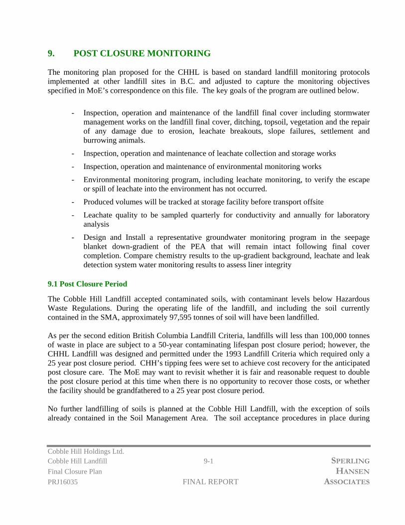
Cobble Hill Holdings Ltd. Cobble Hill Landfill 9-1 SPERLING
Final Closure Plan HANSEN
PRJ16035 FINAL REPORT ASSOCIATES
9. POST CLOSURE MONITORING The monitoring plan proposed for the CHHL is based on standard landfill monitoring protocols implemented at other landfill sites in B.C. and adjusted to capture the monitoring objectives specified in MoE’s correspondence on this file. The key goals of the program are outlined below.
- Inspection, operation and maintenance of the landfill final cover including stormwater management works on the landfill final cover, ditching, topsoil, vegetation and the repair of any damage due to erosion, leachate breakouts, slope failures, settlement and burrowing animals.
- Inspection, operation and maintenance of leachate collection and storage works
- Inspection, operation and maintenance of environmental monitoring works
- Environmental monitoring program, including leachate monitoring, to verify the escape or spill of leachate into the environment has not occurred.
- Produced volumes will be tracked at storage facility before transport offsite
- Leachate quality to be sampled quarterly for conductivity and annually for laboratory analysis
- Design and Install a representative groundwater monitoring program in the seepage blanket down-gradient of the PEA that will remain intact following final cover completion. Compare chemistry results to the up-gradient background, leachate and leak detection system water monitoring results to assess liner integrity
9.1 Post Closure Period
The Cobble Hill Landfill accepted contaminated soils, with contaminant levels below Hazardous Waste Regulations. During the operating life of the landfill, and including the soil currently contained in the SMA, approximately 97,595 tonnes of soil will have been landfilled. As per the second edition British Columbia Landfill Criteria, landfills will less than 100,000 tonnes of waste in place are subject to a 50-year contaminating lifespan post closure period; however, the CHHL Landfill was designed and permitted under the 1993 Landfill Criteria which required only a 25 year post closure period. CHH’s tipping fees were set to achieve cost recovery for the anticipated post closure care. The MoE may want to revisit whether it is fair and reasonable request to double the post closure period at this time when there is no opportunity to recover those costs, or whether the facility should be grandfathered to a 25 year post closure period. No further landfilling of soils is planned at the Cobble Hill Landfill, with the exception of soils already contained in the Soil Management Area. The soil acceptance procedures in place during

Cobble Hill Holdings Ltd. Cobble Hill Landfill 9-2 SPERLING
Final Closure Plan HANSEN
PRJ16035 FINAL REPORT ASSOCIATES
landfill operation, as per SIRM Environmental Procedures Manual/Operation, Maintenance and Surveillance Manual (EPMOMS), are outlined below:
- No hazardous waste, liquids, or putrescible material are discharged into the landfill cell. - Section 6 of the EPMOMS outlines the Soil Acceptance Plan for the site. - Prior to receipt of any contaminated soils, a Waste Approval Application is completed. This
application is completed by the soil generator and includes details such as: land use, land use history, and waste characterization. Waste characterization details include the nature of contamination, physical soil descriptions, soil moisture content, a list of Potential Contaminants of Concern (PCOCs), maximum identified contaminant concentrations and estimated soil quantity.
- The Waste Approval Application must also be accompanied by analytical results from a Canadian Association for Laboratory Accreditation accredited laboratory.
- Soils entering the site are retested for contaminant levels. - Soils which do not demonstrate a risk of containing hazardous waste are directly deposited
into the Permanent Encapsulation Area (PEA). - Soils requiring further characterization are deposited into the Soil Management Area (SMA)
for holding. - The soils landfilled at the CHL are screened for acceptability by Site staff to ensure the soil is
suitable for permanent encapsulation. Unsuitable soils include high debris content or high moisture content and soils that fail verification testing to confirm that the incoming soils are below hazardous waste standards. This screening helps to ensure the soil landfilled in the PEA is essentially inert and considered non-leachable.
The nature of wastes received (non-leachable contaminated soils) and the nature of the double encapsulation system adopted at the Cobble Hill Landfill site far surpass normal landfilling practices in British Columbia. Due to the very low rates of leachate released from the cover system, the relatively low volumes of leachate released, and the significant dilution that will be provided by clean run-off from the final cover system, SHA is of the opinion that the characteristics of soil disposed at CHL will not pose a risk to human health or the environment beyond the 50-year post closure period and that aquatic life water quality objectives will be be achieved at the property line after the post closure maintenance period has ended.
9.2 Environmental Monitoring Plan
A detailed Environmental Monitoring Plan (EMP) for leachate, groundwater, surface water, and landfill gas is outlined in the following section and will be implemented during landfill closure and post closure.
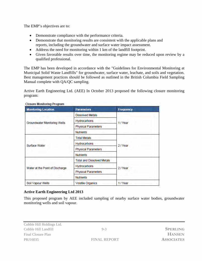
Cobble Hill Holdings Ltd. Cobble Hill Landfill 9-3 SPERLING
Final Closure Plan HANSEN
PRJ16035 FINAL REPORT ASSOCIATES
The EMP’s objectives are to:
Demonstrate compliance with the performance criteria. Demonstrate that monitoring results are consistent with the applicable plans and
reports, including the groundwater and surface water impact assessment. Address the need for monitoring within 1 km of the landfill footprint. Given favorable results over time, the monitoring regime may be reduced upon review by a
qualified professional. The EMP has been developed in accordance with the "Guidelines for Environmental Monitoring at Municipal Solid Waste Landfills" for groundwater, surface water, leachate, and soils and vegetation. Best management practices should be followed as outlined in the British Columbia Field Sampling Manual complete with QA/QC sampling. Active Earth Engineering Ltd. (AEE) In October 2013 proposed the following closure monitoring program:
Active Earth Engineering Ltd 2013
This proposed program by AEE included sampling of nearby surface water bodies, groundwater monitoring wells and soil vapour.

Cobble Hill Holdings Ltd. Cobble Hill Landfill 9-4 SPERLING
Final Closure Plan HANSEN
PRJ16035 FINAL REPORT ASSOCIATES
Based on the changes to the landfills planning / development in early 2017 when the waste disposal permit was cancelled, it is SHA’s opinion that the sampling and monitoring program can be safely scaled back to reflect the reduced tonnage in place and given that the final closure of the PEA covers less than 1Ha of surface area and the waste has been placed in a double lined containment system that exceeds MoE’s design requirements.
9.3 Leachate Monitoring
Leachate Chemistry is required to assist with determining the contaminating lifespan of the landfill. As described in Chapter 5, it is expected that the leachate generation rate will diminish significantly as the site is capped with a geomembrane and overlaying soil layers and the natural consolidation processes are completed. During final closure construction, the current contact water treatment system will be decommissioned. Leachate will be collected in a newly installed leachate storage facility at the toe of the landfill and will be trucked off site to a regulated disposal facility. It is anticipated the leachate tanks will be emptied (by a vac truck) once per month, initially. During leachate removal, leak detection monitoring for the leachate storage tank will be conducted. During this time, or once per month, the leak detection tank will also be monitored. In the event a leak is observed, on the base of the secondary liner system (outlined in Chapter 5), the entire contents of the tank will be removed and the tank will be inspected and repaired or replaced. Interim tanks will be installed to collect all leachate during this time to ensure no spill is made to the environment. As per Hemmera recommendations, leachate and leak detection tank quantity will be recorded during each leachate removal and/or leachate tank monitoring event. This will be correlated to precipitation data to assess and confirm cover integrity and demonstrate there is no correlation between rainfall events and leachate production due to cover liner leaks. SHA recommends leachate monitoring and sampling be conducted from the leachate tank at time of removal and transportation (for the parameters outlined below). Leachate monitoring will be conducted until a Qualified Professional and the Chief Inspector deems otherwise. Monitoring Location Parameters Frequency Leachate Tank Total/Dissolved Metals
Hydrocarbons Physical Parameters Nutrients
During Leachate Removal
9.4 Surface Water Monitoring
Currently surface water monitoring is completed two times per year and consists of taking five samples within a 30-day period. Some of the surrounding creeks are intermittent and only flow

Cobble Hill Holdings Ltd. Cobble Hill Landfill 9-5 SPERLING
Final Closure Plan HANSEN
PRJ16035 FINAL REPORT ASSOCIATES
during saturated conditions. As the landfill will be closed, and no further quarrying will take place, SHA’s surface water monitoring program includes sampling of two stations, a background surface water flow up gradient of the PEA and at the settling pond discharge at spring-freshet and during fall rains. Monitoring Location Parameters Frequency SHA- SW-1 – Settling Pond Discharge SHA-SW-2 – Up Gradient of PEA
Total/Dissolved Metals Hydrocarbons Physical Parameters Nutrients
Spring/Fall changing to annual, fall only after 25 years
9.5 Groundwater Monitoring
SHA proposes groundwater monitoring be conducted at monitoring wells up gradient and downgradient of the PEA. The original waste permit by MoE stated that a minimum of seven groundwater sampling facilities would be installed and maintained. As the landfill and quarry are now closed, SHA proposes a monitoring program consisting of three wells, one background (MW-6) and two downgradient at the property boundary (MW-2 & MW-3). Should significant changes be observed in the groundwater, additional wells existing on the site should be re-introduced to the monitoring program. During groundwater monitoring, the wells should be inspected and any maintenance required on the well caps and standpipes should be preformed. The below table shows the proposed groundwater monitoring schedule. Monitoring Location Parameters Frequency MW-2 (Property Boundary) MW-3 (S/D) (Property Boundary) MW-6 (On-Site, Up-Gradient)
Total/Dissolved Metals Hydrocarbons Physical Parameters Nutrients
Quarterly, changing to Semi Annual spring fall after 10 years and annual fall after 25 years
Locations for monitoring wells, water wells, surface water stations and air sampling stations are presented on Figure 9-1.

Cobble Hill Holdings Ltd. Cobble Hill Landfill 9-6 SPERLING
Final Closure Plan HANSEN
PRJ16035 FINAL REPORT ASSOCIATES
9.6 Seepage Blanket Monitoring
As per Hemmera recommendations, a groundwater monitoring program should be installed in the seepage blanket, down-gradient of the PEA that will remain intact following final cover completion. These results should be compared to upgradient, background, leachate and leak detection system water to assess liner integrity. The seepage blanket monitoring will be conducted from two standpipe monitoring wells excavated approximately 3.0 m into the seepage blanket at the landfill toe. Conductivity readings from the wells should be collected quarterly and detailed water quality analysis should be conducted annually.
9.7 Landfill Gas Monitoring and Ambient Air Monitoring
As the landfill is not a Municipal Waste Landfill and the gas generation rate for the types of waste being landfilled is extremely slow if at all, Landfill Gas is not deemed to be of great concern at the site. The current soil cell (PEA) has been capped with 40 mil LLDPE liner since the Fall of 2016 (approx. 7 months). The cap liner is considered to be 95% complete with minor welding needed to be finalized. The landfill cell is not currently being held down with significant weight. Since installation, no uplifting of the liner due to landfill gas has been observed. Given the final cover system is not yet complete, SHA does not foresee volatile gases being a issue at this site. A review of leachate testing has indicated that VOC’s are generally non detect in the leachate. Therefore; release of volatile organic compounds through the barrier layer is no longer a concern. This should be verified with a one time monitoring run of VOC’s emissions from the landfill. A VOC instrument will be used to sample from a minimum of 10 locations (1 sample per 200 m2) or as directed by the Chief Inspector. Should the annual testing confirm that the landfill cap is preventing the release of any VOC’s then the number of sampling locations could be reduced. Even though the risk is deemed to be low, no permanent structures should be built on top of the landfill unless they are constructed with properly ventilated foundations. Also, standard confined space entry procedures must be followed when entering any manholes or other structures on or near the landfill site as landfill gas can accumulate in such structures over time. Additionally, ambient air monitoring was required due to potential dust concerns from soil mixing, blasting, mining and landfilling activities. Given there is no activity currently in operation at the site, SHA does not foresee the need for continued monitoring for air quality.
9.8 Geotechnical Inspection
A geotechnical inspection should be initiated on an annual basis to inspect the landfill footprint. This inspection should also include checking the cover for potential problems arising from slumping,

Cobble Hill Holdings Ltd. Cobble Hill Landfill 9-7 SPERLING
Final Closure Plan HANSEN
PRJ16035 FINAL REPORT ASSOCIATES
cracking or erosion, and determining the state of other infrastructure that does not receive regular inspection. If significant issues with infrastructure are identified, a Qualified Professional should be retained to resolve them.
9.9 Post Closure Inspection
An annual inspection of all infrastructure will be completed by a Qualified Professional prior to compilation of the annual report. This inspection will include the following:
Final Cover System Ditching Topsoil / Vegetation Erosion Potential Leachate Breakouts – not expected with geosythetic basal and final cover
geomembrane system Leachate Collection, Conveyance and Storage Facility Environmental Monitoring Infrastructure.
Any observed inefficiencies will be recorded and remedied as required.
9.10 Annual Report
Each year a Qualified Professional will collect the required monitoring data and compile an Annual Report outlining the closure performance of the landfill. Each year the Qualified Professional will assess the groundwater and surface water quality for potential impacts and evaluate the leachate generation rate and quality. All infrastructure maintenance and improvements identified in the post closure inspection are to be outlined in the annual report. In each report the Qualified Professional will make recommendations on the existing monitoring program and identify any changes that would improve the post closure monitoring. Surface water structures will be investigated during monitoring events at the site. Ditches and downchutes will be maintained to ensure proper drainage at the site, and to minimize the potential of erosion of surrounding structures. As part of the on-going leachate collection and off-site treatment, the system will be investigated for operational effectiveness. The double lined leachate storage facility will allow for leak detection monitoring, as outlined previously. Maintenance will be completed as required.
9.11 Adjustments to Monitoring Programs Over Time
For many years SHA has recognized there is a strong correlation between electrical conductivity and leachate impacts in groundwater at landfill sites in B.C. It is recommended that at the CHHL landfill electrical conductivity be recorded during each sample run and that the quarterly environmental

Cobble Hill Holdings Ltd. Cobble Hill Landfill 9-8 SPERLING
Final Closure Plan HANSEN
PRJ16035 FINAL REPORT ASSOCIATES
monitoring samples be correlated to conductivity for the first 10 years of sampling. Provided that a good level of correlation exists, SHA recommends that laboratory sampling of groundwater and leachate be scaled back from quarterly to semi-annual after 10 years of sampling, and from semi annual to annual after 25 years of sampling provided that trend lines continue to show steady state or improving water quality conditions. The monitoring program should be reviewed by a qualified professional in years 10 and 25 to confirm these recommendations which are carried in the financial plan.
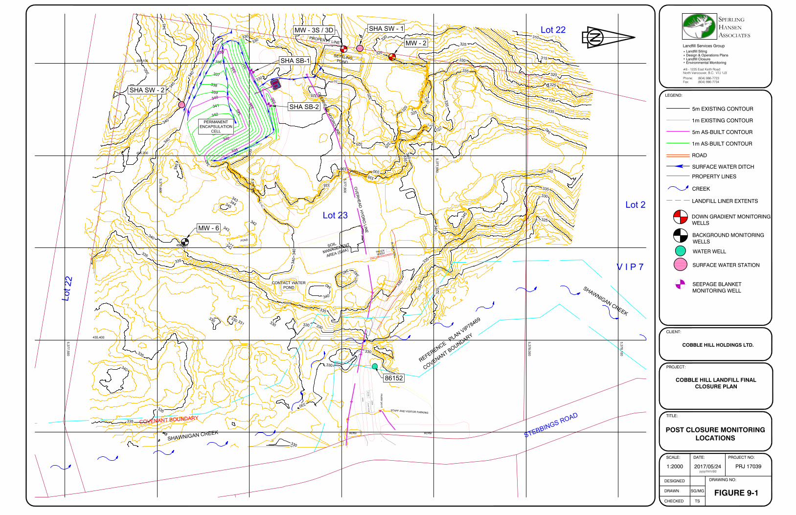
3
2
0
320
3
2
0
325
3303
3
0
3
3
0
3
3
0
3
3
0
3
3
5
3
3
5
3
4
0
3
4
0
325
3
3
0
3
3
5
3
4
0
3
4
0
3
4
0
3
3
0
3
3
0
335
3
3
5
3
4
0
3
4
0
335
330
3
3
0
3
3
0
340
330
3
2
8
329
3
3
1
3
3
2
333 3
3
4
3
3
5
3
3
6
3
2
0
3
2
5
3
3
5
3
3
0
3
4
0
335
3
4
0
3
2
5
3
4
1
3
3
9
325
3
2
4
3
4
0
3
4
0
3
3
5
3
4
0
3
3
8
3
3
9
3
4
1
3
4
5
3
4
6
3
4
5
3
3
9
3
3
5
340
3
4
5
S
T
E
B
B
I
N
G
S
R
O
A
D
BERM
BERM
SC
ALE
SC
ALE
OF
FIC
ES
CA
LE
H
OU
SE
ST
AF
F A
ND
VIS
ITO
R P
AR
KIN
G
S
O
IL
M
A
N
A
G
E
M
E
N
T
A
R
E
A
(
S
M
A
)
C
O
V
E
N
A
N
T
B
O
U
N
D
A
R
Y
muster point
T
R
U
C
K
W
A
S
H
S
H
A
W
N
IG
A
N
C
R
E
E
K
Lot 21
Lot 23
B
L
O
C
K
W
A
L
L
CONTACT WATER
POND
P
R
O
P
E
R
T
Y
L
IN
E
S
E
T
T
L
IN
G
P
O
N
D
Lot 22
L
o
t 2
2
V I P 7 8 4 5 9
R
E
F
E
R
E
N
C
E
P
L
A
N
V
I
P
7
8
4
6
9
CO
VE
NA
NT
BO
UN
DA
RY
pow
er pole
O
V
E
R
H
E
A
D
H
Y
D
R
O
L
I
N
E
P
O
N
D
S
H
A
W
N
I
G
A
N
C
R
E
E
K
O
V
E
R
H
E
A
D
H
Y
D
R
O
L
IN
E
455,100
455,200
455,300
455,400
5,377,500
5,377,600
5,377,700
5,377,800
5,377,900
5,378,000
5,378,100
345
3
5
0
3
4
0
3
3
5
3
3
5
3
3
5
3
4
0
330
325
330
335
340
335
330
325
320
315
310
325
330
335
330
330
3
3
0
3
3
0
3
3
0
3
3
1
3
4
3
3
4
43
4
5
3
4
2
3
4
3
3
4
1
3
4
2
3
4
2
3
4
3
3
4
0
3
3
8
3
3
7
3
3
6
3
3
5
3
4
0
3
4
0
3
4
0
3
3
5
3
3
5
3
3
0
3
3
1
3
3
5
(D
E
C
O
M
IS
S
IO
N
E
D
)
MW - 2
MW - 3S / 3D
MW - 6
86152
SHA SW - 1
PERMANENT
ENCAPSULATION
CELL
SHA SW - 2
SHA SB-1
SHA SB-2
LEGEND:
CLIENT:
PROJECT:
TITLE:
SCALE:
DESIGNED
DRAWN
CHECKED
DRAWING NO:
SG/MG
TS
DATE: PROJECT NO:
FIGURE 9-1
COBBLE HILL LANDFILL FINALCLOSURE PLAN
COBBLE HILL HOLDINGS LTD.
POST CLOSURE MONITORINGLOCATIONS
1:2000 2017/05/24 PRJ 17039yyyy/mm/dd
(604) 986-7734(604) 986-7723
North Vancouver, B.C. V7J 1J3#8 - 1225 East Keith Road
Environmental Monitoring
Design & Operations Plans
Landfill Services Group
Fax:Phone:
Landfill Closure
Landfill Siting
SSOCIATES
S PERLING ANSENHA
5m EXISTING CONTOUR
1m EXISTING CONTOUR
5m AS-BUILT CONTOUR
1m AS-BUILT CONTOUR
ROAD
SURFACE WATER DITCH
PROPERTY LINES
N
CREEK
LANDFILL LINER EXTENTS
DOWN GRADIENT MONITORINGWELLS
WATER WELL
SURFACE WATER STATION
BACKGROUND MONITORINGWELLS
SEEPAGE BLANKETMONITORING WELL

Cobble Hill Holdings Ltd. Permit No. 105809 10-1 SPERLING
Closure Plan HANSEN
PRJ16035 FINAL REPORT ASSOCIATES
10. Costing The following closure costs and post closure period bonding / security posting reflect the current conditions at the site and the potential risk posed to the environment based on final closure to the PEA. Currently, one fully encapsulated and contaminated soil cell exists at the CHL which has been completely lined and closed off with 40 mil LLDPE geomembrane since the Fall of 2016 (approx. 7 months). CHH is fully committed to performing final closure works to the PEA in 2017 based on approval of the Final Closure Plan by MoE no later than June 15th, 2017. CHH is prepared to begin closure works by July 1st, 2017 and understands closure construction must be completed by October 31st, 2017. Post closure monitoring will begin after closure works are complete. 10.1 Closure of the Permanent Encapsulation Area Currently, there is one fully lined and covered waste soil cell (PEA) onsite. A small amount of leachate is being managed by South Island Resource Management (SIRM) for which leachate flows from the PEA have steadily declined since capping the area in the Fall of 2016. As outlined previously in this report, SHA endorses final closure of the PEA in the near future, as directed by MoE as long as all of the construction work can be completed before the winter rains set in this fall. The final closure works proposed in this report have covered the issues identified by MoE and will be completed in a manner that will have little to no impact to the receiving environment. These environmental control improvements include;
Extending and Upgrading the primary (liner) and secondary (clay) basal liner system; Extending & Upgrading the leak detection and leachate collection system; Stabilizing the outer slopes to 3H:1V; Upgrading the liner system on the slopes to include textured geomembrane and gravel
drainage layers; Topsoil and vegetation cover to promote a healthy grass, plant and shrub community post
closure and to achieve effective erosion control; Surface water controls to keep clean water clean and minimize leachate production; Easily managed, low maintenance leachate collection, cleanouts, storage and monitoring; and Post closure monitoring and sampling regime.
The final closure costs are outlined on the attached Table 10-1 and include:
PEA Subgrade Earthworks $ 20,188 Closure System on Slopes $123,343 Closure System on Crest $ 63,537 Surface Water Mgmt $ 7,346 Basal Liner System Upgrades $ 23,550 Leachate Storage Facility Upgrades $ 25,000 Engineering and QAQC $ 20,000 Sub-Total $282,964

Cobble Hill Holdings Ltd. Permit No. 105809 10-2 SPERLING
Closure Plan HANSEN
PRJ16035 FINAL REPORT ASSOCIATES
10.2 Post Closure Monitoring Costs CHH is committed to implementing a rigorous monitoring program during the 50-year post closure period based on the Landfill Criteria for Municipal Solid Waste Guidelines. The maintenance and monitoring program will include the following tasks, outlined as annual costs and further detailed on Table 10-2:
Sampling and Analysis for SW, GW & Leachate $4,500 Cover System Maintenance $1,500 Op’s and Maintenance of Leachate Facility $1,000 Leachate Disposal Costs $3,065 Op’s and Maintenance for Site Infrastructure $1,500 Engineering and Reporting $3,000 Sub-Total (inc. 3rd Party Mark-Up) $14,865
Post closure costs to support future monitoring and maintenance will be completed by administrative and field staff with qualified professional oversight and sign off. Projecting the annual Post Closure sampling, monitoring, analysis and reporting costs over the 50-year Post Closure Period sum up to $743,220 without adjusting entries for reductions to the monitoring program in time (assuming conditions stabilize) and no adjustments for inflation and interest earned on the security. On making adjustments to scale back the monitoring to semi annual in year 11 and to annual in year 25, and scaling back cover system maintenance in year 25, assuming that by then the cover has well established mature and stable vegetation, the overall costs decrease to $587,595 before discounting. 10.3 Amount of Closure and Post Closure Bond Table 10-2 presents the estimated costs for final closure of the current cell based on the above assumptions, including a 20% contingency. The total cost of the updated capital costs are $282,964 and the total environmental monitoring costs are $587,595 before net present value adjustments. As required in the Criteria Section 8.4, the net present value calculations were based on the 10 year average inflation rate as per the Consumer Price Index at 1.46%. The Government of Canada long-term bond yield is currently 1.86%, but has been much higher in years past. As per Section 8.4 of the Criteria the difference between the Discount Rate and the Inflation Rate shall be set at 2% to recognize long term trends between these two key parameters. When the costs are adjusted for inflation and future costs are discounted to net present values according to guidance in Section 8.4 of the Landfill Criteria the total post closure requirements decrease to $385,363, as presented in Table 10-3. With a 20% contingency, the post closure bonding amount should increase to $462,435 if it is concluded that a 50 year monitoring period is required. If it is concluded that a 25 year post closure care period is appropriate, then a post closure cost of $319,785 should be applied, with the 20% contingency included, as shown in Table 10-4. The closure plan and security posting will be reviewed every five years as specified in Section 4.1 of the permit, see attached in Appendix A.

Cobble Hill Holdings Ltd. Permit No. 105809 10-3 SPERLING
Closure Plan HANSEN
PRJ16035 FINAL REPORT ASSOCIATES
As mentioned previously in Chapter 4, based on SHA’s guidance, the CHH closure works are being completed at a very high standard, well in excess of the minimum specifications in the Landfill Criteria. In SHA’s professional opinion this is by far the best method to manage long term risk and the Ministry should recognize this commitment and the value it will bring to reducing risk in the overall setting of the final bond value.

Permanent Encapsulation Area ‐ Closure Cost Estimate UnitsEstimated Quantity
Unit Price Total
Trim & Remove Existing Smooth LLDPE Geomembrane (from Crest to Toe) on North and East Slopes of PEA ea 1 2,000.00$ 2,000$ Remove, Haul and Compact Soil from SMA to PEA on North and East Slopes m3 1,867 3.10$ 5,788$ Cut and Fill Existing PEA Soil to create 3H:1V Slopes on North and East Slopes m3 6,200 2.00$ 12,400$
$ 20,188
Suppy and Install 12oz. Non‐Woven Geotextile m2 4,340 3.00$ 13,020$ Supply and Intall 40 mil Double Textured LLDPE Geomembrane Liner m2 4,340 9.00$ 39,060$ Suppy and Install 12oz. Non‐Woven Geotextile m2 4,340 3.00$ 13,020$ Supply and Install 200mm 5‐25mm Crushed Gravel Drainage Layer m2 4,340 6.00$ 26,040$ Supply and Install 8oz. Non‐Woven Geotextile m2 4,340 2.00$ 8,680$ Supply and Install 300mm Topsoil Vegetative Layer m2 4,340 4.35$ 18,879$ Supply and Install Erosion Control Matting along Top Side of Toe Ditch with Straw Wattle & Straw Bales lm 170 12.00$ 2,040$ Hydroseeding of Topsoil / Vegetative Layer m2 4,340 0.60$ 2,604$
$ 123,343
Complete Existing 40mil LLDPE Geomembrane Liner Repairs ea 1 1,500.00$ 1,500$ Supply and Install 200mm Sand Drainage / Friction Layer over Existing 40 mil Smooth LLDPE Geomebrane m2 3,660 4.00$ 14,640$ Supply and Install 8oz. Non‐Woven Geotextile Separation Layer m2 3,660 2.00$ 7,320$ Supply and Install 500mm of Clean Fill Subsoil Layer m2 3,660 6.00$ 21,960$ Supply and Install 300mm Topsoil Vegetative Layer m2 3,660 4.35$ 15,921$ Hydroseeding of Topsoil / Vegetative Layer m2 3,660.0 0.60$ 2,196$
$ 63,537
Construct Crest Surface Water Ditching & Armoring lm 204 14.00$ 2,856$ Construct Toe Surface Water Ditching & Armoring (inc. Compacted Soil Berm) lm 170 19.00$ 3,230$ Construct Surface Water Conveyance Ditching & Armoring from PEA to Existing Settling Pond lm 90 14.00$ 1,260$
$ 7,346
Extend and Construct the Secondary Clay Liner System on Grade towards the North and East based on Slope Re‐Grade m2 510 7.00$ 3,570$ Extend the Leak Detection System including Sand Drainage Layer and Notch in Clay for Leak Detection Piping lm 100 45.00$ 4,500$ Extend and Construct the Primary Geomembrane Liner Sytem on Grade towards the North and East based on Slope Re‐Grade m2 510 18.00$ 9,180$ Construct Additional Leachate Collection Sand Drainage Layer & Piping along the North Side of the PEA ‐ Perforated HDPE Pipe lm 100 45.00$ 4,500$ Construct Leachate Tie‐In and Clean Outs and Associated Conveyance Piping ea 6 300.00$ 1,800$
$ 23,550
Construct Secondary Lock Block Well with 60mil HDPE Liner System ea 1 15,000.00$ 15,000$ Supply and Install Primary Containment 10,000 gal Leachate and 2,500 gal Leak Detection Tank ea 1 8,000.00$ 8,000$ Consruct Roof Structure over Leachate Storage Facility ea 1 2,000.00$ 2,000$
$ 25,000
Construction Supervision and QAQC ea 1 20,000.00$ 20,000$ 20,000$
282,964$
Table 10‐1 Closure Costs
PEA Subgrade Earthworks
Closure System on Slopes (4,340 m2 closure area)
Closure System on Crest (3,660 m2 closure area)
Surface Water Management
Sub‐Total
Basal Liner System Upgrades
Leachate Storage Facility Upgrades
Engineering & QAQC
Cobble Hill Holdings Ltd.Cobble Hill LandfillFinal Closure PlanPrj17039
SperlingHansen
Associates
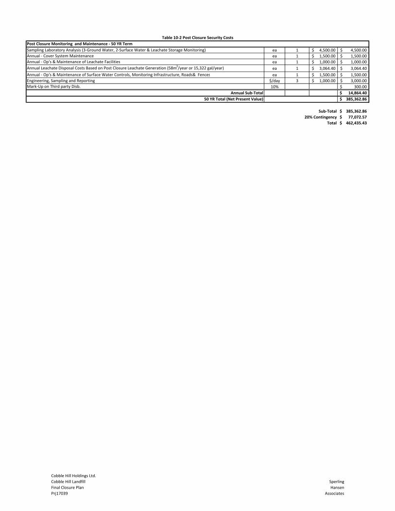
Sampling Laboratory Analysis (3‐Ground Water, 2‐Surface Water & Leachate Storage Monitoring) ea 1 4,500.00$ 4,500.00$ Annual ‐ Cover System Maintenance ea 1 1,500.00$ 1,500.00$ Annual ‐ Op's & Maintenance of Leachate Facilities ea 1 1,000.00$ 1,000.00$ Annual Leachate Disposal Costs Based on Post Closure Leachate Generation (58m3/year or 15,322 gal/year) ea 1 3,064.40$ 3,064.40$ Annual ‐ Op's & Maintenance of Surface Water Controls, Monitoring Infrastructure, Roads& Fences ea 1 1,500.00$ 1,500.00$ Engineering, Sampling and Reporting $/day 3 1,000.00$ 3,000.00$ Mark‐Up on Third party Disb. 10% 300.00$
Annual Sub‐Total 14,864.40$
50 YR Total (Net Present Value) 385,362.86$
385,362.86$
20% Contingency 77,072.57$
Total 462,435.43$
Post Closure Monitoring and Maintenance ‐ 50 YR Term
Sub‐Total
Table 10‐2 Post Closure Security Costs
Cobble Hill Holdings Ltd.Cobble Hill LandfillFinal Closure PlanPrj17039
SperlingHansen
Associates

Table 10‐3 Net Cost Adjustment for Inflation and Interest Table 10‐4 Net Cost Adjustment for Inflation and Interest
Annual Cost Interest 385,362.86$ Annual Cost Interest 266,487.51$
1 14,864.40$ 2% 378,205.72$ 1 14,864.40$ 2% 256,952.86$ 2 14,864.40$ 2% 370,905.43$ 2 14,864.40$ 2% 247,227.51$ 3 14,864.40$ 2% 363,459.14$ 3 14,864.40$ 2% 237,307.66$ 4 14,864.40$ 2% 355,863.92$ 4 14,864.40$ 2% 227,189.42$
5 14,864.40$ 2% 348,116.80$ 5 14,864.40$ 2% 216,868.80$ 6 14,864.40$ 2% 340,214.74$ 6 14,864.40$ 2% 206,341.78$ 7 14,864.40$ 2% 332,154.63$ 7 14,864.40$ 2% 195,604.22$ 8 14,864.40$ 2% 323,933.32$ 8 14,864.40$ 2% 184,651.90$ 9 14,864.40$ 2% 315,547.59$ 9 14,864.40$ 2% 173,480.54$
10 14,864.40$ 2% 306,994.14$ 10 14,864.40$ 2% 162,085.75$ 11 12,614.40$ 2% 300,519.62$ 11 12,614.40$ 2% 152,713.06$ 12 12,614.40$ 2% 293,915.62$ 12 12,614.40$ 2% 143,152.93$ 13 12,614.40$ 2% 287,179.53$ 13 12,614.40$ 2% 133,401.58$ 14 12,614.40$ 2% 280,308.72$ 14 12,614.40$ 2% 123,455.22$
15 12,614.40$ 2% 273,300.49$ 15 12,614.40$ 2% 113,309.92$ 16 12,614.40$ 2% 266,152.10$ 16 12,614.40$ 2% 102,961.72$ 17 12,614.40$ 2% 258,860.75$ 17 12,614.40$ 2% 92,406.55$ 18 12,614.40$ 2% 251,423.56$ 18 12,614.40$ 2% 81,640.28$ 19 12,614.40$ 2% 243,837.63$ 19 12,614.40$ 2% 70,658.69$ 20 12,614.40$ 2% 236,099.98$ 20 12,614.40$ 2% 59,457.46$ 21 12,614.40$ 2% 228,207.58$ 21 12,614.40$ 2% 48,032.21$ 22 12,614.40$ 2% 220,157.34$ 22 12,614.40$ 2% 36,378.46$ 23 12,614.40$ 2% 211,946.08$ 23 12,614.40$ 2% 24,491.63$ 24 12,614.40$ 2% 203,570.60$ 24 12,614.40$ 2% 12,367.06$ 25 12,614.40$ 2% 195,027.62$ 25 12,614.40$ 2% 0.00$ 26 9,989.40$ 2% 188,938.77$ 27 9,989.40$ 2% 182,728.14$ 28 9,989.40$ 2% 176,393.31$ 29 9,989.40$ 2% 169,931.77$ 30 9,989.40$ 2% 163,341.01$ 31 9,989.40$ 2% 156,618.43$ 32 9,989.40$ 2% 149,761.40$ 33 9,989.40$ 2% 142,767.22$ 34 9,989.40$ 2% 135,633.17$ 35 9,989.40$ 2% 128,356.43$ 36 9,989.40$ 2% 120,934.16$ 37 9,989.40$ 2% 113,363.44$ 38 9,989.40$ 2% 105,641.31$ 39 9,989.40$ 2% 97,764.74$ 40 9,989.40$ 2% 89,730.63$ 41 9,989.40$ 2% 81,535.85$ 42 9,989.40$ 2% 73,177.16$ 43 9,989.40$ 2% 64,651.31$ 44 9,989.40$ 2% 55,954.93$ 45 9,989.40$ 2% 47,084.63$ 46 9,989.40$ 2% 38,036.93$ 47 9,989.40$ 2% 28,808.26$ 48 9,989.40$ 2% 19,395.03$ 49 9,989.40$ 2% 9,793.53$ 50 9,989.40$ 2% (0.00)$
587,595.00$ Total 50 Year Cost before discounts 337,860.00$ Total 25 Year Cost before discounts385,362.86$ Net Value 50 Years 266,487.51$ Net Value 25 Years462,435.43$ Net Value 50 Years with 20% Cont. 319,785.01$ Net Value 25 Years with 20% Cont.
Cobble Hill Holdings Ltd.Cobble Hill LandfillFinal Closure PlanPrj17039
SperlingHansen
Associates

APPENDICES

APPENDIX A Permits and Certificates
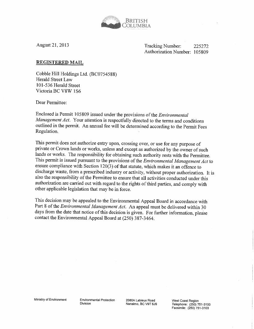


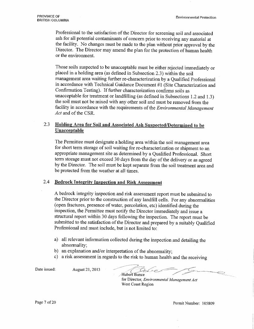

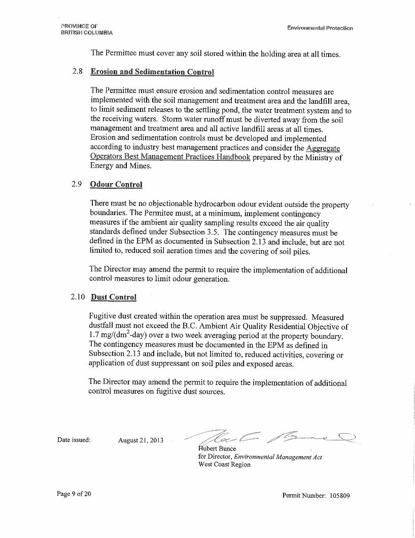


Environmental Protection Division Ministry of Environment 2080A Labieux Rd Nanaimo BC V9T 6J9
Authorizations - South Telephone: (250) 751 3100 Facsimile: (250) 751 3103
June 4, 2015 Tracking Number: 338485 Authorization Number: 105809 Cobble Hill Holdings Ltd. (BC0754588) Herald Street Law 101 - 536 Herald Street Victoria BC V8W 1S6 Dear Cobble Hill Holdings Ltd. (BC0754588), Re: Environmental Appeal Board Directions - Amendments to the Permit under the Environmental Management Act On March 20, 2015, the Environmental Appeal Board confirmed the permit subject to directions. A copy of the decision, including directions, is available at the Environmental Appeal Board’s website http://www.eab.gov.bc.ca/index.htm. Pursuant to the Environmental Management Act, Permit 105809 is hereby amended: 1. To amend the subject sentence of section 2.14 Advisory Committee from:
The Committee must be composed of one representative of each relevant regulatory agency and one representative from the local government.
to:
The Committee must be composed of one representative of each relevant regulatory agency, one representative from the local government, one representative from the Shawnigan Residents Association and/or other interested community members as chosen by the Director.
2. To add section:
2.4.1 Reuse of Landfill Cell Liners Prohibited
Reuse of geomembrane landfill cell liners is prohibited. This prohibition must be included in the Environmental Procedures Manual.

June 4, 2015 2 Tracking Number: 338485 Authorization Number: 105809
3. Effective March 20, 2016, to amend section 2.7 Weather Protection from:
2.7 Weather Protection
The Permittee must cover the soil treatment piles, soil holding area and active landfill areas completely from November to April when not actively worked on and provide sufficient weather protection and containment for nutrients stored at the site for the protection of human health and the environment. The Permittee must cover any soil stored within the holding area at all times.
to: 2.7 Weather Protection
A permanent roof must be placed over, cover, and prevent precipitation from entering the soil management and bio-remediation treatment area including the temporary soil holding area (as described under subsection 2.3), referred to in subsection 1.2.1.
The Permittee must cover the active landfill areas completely from November to April when not actively worked on and provide sufficient weather protection and containment for nutrients stored at the site for the protection of human health and the environment.
4. To add section:
2.7.1 Wheel Rinsing
Before soil transport vehicles leave the site, their wheels must be rinsed to remove all soil and waste. Soil and waste must be managed in accordance with the permit. Rinse water must be directed to the leachate and leak detection reservoir(s). These requirements must be included in the Environmental Procedures Manual.
5. To add to section 3.6 Receiving Environment Sampling, Table, Row 3 Surface Water, Column 3 Frequency:
Immediately after a 1-in-200 year, 24-hour storm event, at Monitoring Locations (SW-2) Ephemeral Creek 1 and (SW-3) Ephemeral Creek 2.
Please note that although a revised permit has not been produced at this time, a copy of this letter is being placed on the permit file, as an addendum to the permit. Your attention is respectfully directed to the conditions of the permit. An annual fee for the permit will be determined in accordance with the Permit Fees Regulation.

June 4, 2015 3 Tracking Number: 338485 Authorization Number: 105809
This permit does not authorize entry upon, crossing over, or use for any purpose of private or Crown lands or works, unless and except as authorized by the owner of such lands or works. The responsibility for obtaining such authority rests with the permittee. This permit is issued pursuant to the provisions of the Environmental Management Act to ensure compliance with Section 120(3) of that statute, which makes it an offence to discharge waste, from a prescribed industry or activity, without proper authorization. It is also the responsibility of the permittee to ensure that all activities conducted under this authorization are carried out with regard to the rights of third parties, and comply with other applicable legislation that may be in force. This decision may be appealed to the Environmental Appeal Board in accordance with Part 8 of the Environmental Management Act. An appeal must be delivered within 30 days from the date that notice of this decision is given. For further information, please contact the Environmental Appeal Board at (250) 387-3464. Administration of this permit will be carried out by staff from the regional office. Plans, data and reports pertinent to the permit are to be submitted to the Regional Director, at Ministry of Environment, Environmental Protection Division, Authorizations - South, 2080A Labieux Rd, Nanaimo BC V9T 6J9. Yours truly,
A.J. Downie, M.Sc., P.Ag. for Director, Environmental Management Act CC: Environment Canada Ministry of Energy and Mines ENCL: None

PROVINCE OF BRITISH COLUMBIA MINISTRY OF ENERGY, MINES AND PETROLEUM RESOURCES
QUARRY PERMIT
Amendment: April 20 2009
APPROVING WORK SYSTEM AND RECLAMATION PROGRAM
(Issued pursuant to Section 10 of the Mines Act R.S.B.C. 1996, C.293)
Permit: Q-8-094 Mine No.: 1610355 Issued to: South Island Aggregates Ltd
497 A Garbally Road
Victoria BC V8T 2J9
For work located at the following property: South Island Aggregates Quarry
Lot 23, Blocks 156, 201 and 323, Malahat District, Plan VIP78459
This approval and permit is subject to the appended conditions. Issued this 4th day October in the year 2006
Amended this 20th day of April, in the year 2009
Amended this 17th day of July in the year 2015
__________________________________ Al. Hoffman. P. Eng Chief Inspector

South Island Aggregates Permit No. Q-8-094 Page 2 of 15 April 9, 2006
INTRODUCTION
This amendment issued July 17, 2015, replaces all previous permits and subsequent amendments. It incorporates conditions established through previous amendments and, as a result of the meeting with the Chief Inspector of Mines following discussions related to hours of work. In addition, it includes conditions established by the Senior Inspector of Mines to address concerns associated with the operation of this quarry. This amendment issued July 17, 2015 includes the change of end land use and includes the conditions necessary to construct and operated the Waste Cells in accordance with, and in addition to, the Ministry of Environment Permit “PR-105809”. This amendment includes conditions as required by the ruling of the Environmental Appeal Board Decision Nos. 2013-EMA-15(b) and 2013-EMA-019(c) PREAMBLE Notice of intention to commence work on a quarry, including a plan of the proposed work system and a program for the protection and reclamation of the surface of the land and watercourses affected by the work dated August 23, 2006, was filed with the Inspector on August 23, 2006. Notice of such filing was published in The Pictorial on September 3, 2006, and in the BC Gazette on September 7, 2006. This permit contains the requirements of the Ministry of Energy and Mines for reclamation. It is also compatible, to the extent possible, with the requirements of other provincial ministries for reclamation issues. The amount of security required by this permit, and the manner in which this security may be applied, will also reflect the requirements of those ministries. Nothing in this permit, however, limits the authority of other provincial ministries to set other conditions, or to act independently, under their respective permits and legislation. This amendment references and includes terms of the following Reports:
1. Active Earth Engineering (AEEL) “Technical Assessment for Authorization to Discharge Waste”, August 2012.
2. Active Earth Engineering, “Geotechnical Assessment”, October 24, 2013. 3. Levelton Consultants Ltd “South Island Aggregates Stebbings Road Quarry”,
October 2012. 4. BC Geological Survey “Bedrock Geology of the South Island Aggregates
Stebbings Road Quarry” October 28, 2013. 5. Active Earth Engineering, “Summary of Core Drilling and Testing Results”,
October 2013.

South Island Aggregates Permit No. Q-8-094 Page 3 of 15 April 9, 2006
6. Active Earth Engineering “Environmental Procedures Manual for Waste Discharge Permit PR-105809", October 28, 2013.
7. Leveloton Consultants Ltd follow-up memo “South Island Aggregates Containment Area-640 Stebbings Road, Shawnigan Lake, BC”, November 13, 2013.
Unless modified by Permit Q-8-094, or the Ministry of Environment Permit PR-105809, all terms of the referenced report form a part of this permit. Should there be a conflict between this permit and the Ministry of Environment (MOE) permit related to requirements under the terms of the MOE permit related to environmental protection, the terms of the MOE permit shall take precedence. Decisions made by staff of the Ministry of Energy and Mines will be made in consultation with other ministries. CONDITIONS The Chief Inspector of Mines (Chief Inspector) hereby approves the work plan and the program for protection and reclamation of the land surface and watercourses subject to compliance with the following conditions: Unless modified by this amended permit all conditions within the original Notice of Work, dated August 23, 2006, and the subsequent amendment form an integral part of this permit. 1. Reclamation Security (a) The owner, agent or manager (herein called the Permittee) shall maintain
with the Minister of Finance securities in the amount of five thousand dollars ($55,000). The security will be held by the Minister of Finance for the proper performance of the approved program and all the conditions of this permit in a manner satisfactory to the Chief Inspector.
(b) The Permittee shall conform to all forest tenure requirements of the
Ministry of Forests. Should the Permittee not conform to these requirements then all or part of the security may be used to cover the costs of these requirements.
(c) The Permittee shall conform to all Ministry of Environment approval,
licence and permit conditions, as well as requirements under the Wildlife
Act. Should the Permittee not conform to these conditions, then all or part of the security may be used to fulfill these requirements.

South Island Aggregates Permit No. Q-8-094 Page 4 of 15 April 9, 2006
2. Land Use The surface of the land and watercourses shall be reclaimed to the following land
use: Industrial Encapsulated Contaminated Soil containment cells 3. Productivity The level of land productivity to be achieved on reclaimed areas shall not be less
than existed prior to mining on an average property basis unless the Permittee can provide evidence which demonstrates, to the satisfaction of the Chief Inspector, the impracticality of doing so.
4. Revegetation Land shall be re-vegetated to a self-sustaining state using appropriate plant
species. 5. Use of Suitable Growth Medium (a) On all lands to be revegetated, the growth medium shall satisfy land use,
productivity, and water quality objectives. Topsoil and overburden (to rooting depth) shall be removed from operational areas prior to any disturbance of the land and stockpiled separately on the property for use in reclamation programs, unless the Permittee can provide evidence which demonstrates, to the satisfaction of the Chief Inspector, that reclamation objectives can otherwise be achieved.
(b) No topsoil shall be removed from the property without the specific written
permission of the Inspector. 6. Buffer Zones and Berms Buffer zones and/or berms shall be established between the mine and the
property boundary unless exempted in writing by the Inspector. 7. Treatment of Structures and Equipment Prior to abandonment, and unless the Chief Inspector has made a ruling
otherwise, such as heritage project consideration or industrial use:

South Island Aggregates Permit No. Q-8-094 Page 5 of 15 April 9, 2006
(a) all machinery, equipment and building superstructures shall be removed;
(b) concrete foundations shall be covered and revegetated unless,
because of demonstrated impracticality, they have been exempted by the Inspector; and,
(c) all scrap material shall be disposed of in a manner acceptable to
the Inspector. 8. Watercourses (a) Watercourses shall be reclaimed to a condition that ensures: (1) long-term water quality is maintained to a standard acceptable to
the Chief Inspector; (2) drainage is restored either to original watercourses or to new
watercourses which will sustain themselves without maintenance: and,
(3) use and productivity objectives are achieved and the level of
productivity shall not be less than existed prior to mining unless the Permittee can provide evidence which demonstrates to the satisfaction of the Chief Inspector the impracticality of doing so.
(b) Water which flows from disturbed areas shall be collected and diverted
into settling ponds. 9. Roads (a) All roads shall be reclaimed in accordance with land use objectives
unless permanent access is required to be maintained. (b) Individual roads will be exempted from the requirement for total
reclamation under condition 9(a) if either: (1) the Permittee can demonstrate that an agency of the Crown has
explicitly accepted responsibility for the operation, maintenance and ultimate deactivation and abandonment of the road, or

South Island Aggregates Permit No. Q-8-094 Page 6 of 15 April 9, 2006
(2) the Permittee can demonstrate that another private party has explicitly agreed to accept responsibility for the operation, maintenance and ultimate deactivation and abandonment of the road and has, in this regard, agreed to comply with all the terms and conditions, including bonding provisions, of this reclamation permit, and to comply with all other relevant provincial government (and federal government) regulatory requirements.
10. Disposal of Fuels and Toxic Chemicals Fuels, chemicals or reagents which cannot be returned to the
manufacturer/supplier are to be disposed of as directed by the Chief Inspector in compliance with municipal, regional, provincial and federal statutes.
11. Temporary Shutdown If this quarry ceases operation for a period longer than one year the Permittee
shall either continue to carry out the conditions of the permit or apply for an amendment setting out a revised program for approval by the Chief Inspector.
12. Safety Provisions All safety and other provisions of the Mines Act shall be complied with to the
satisfaction of the Chief Inspector. 13. Monitoring The Permittee shall undertake monitoring programs, as required by the
Inspector, to demonstrate that reclamation objectives are being achieved. 14. Alterations to the Program Substantial changes to the program must be submitted to the Inspector for
approval. 15. Notice of Closure Pursuant to Part 10.6.1 of the Health, Safety and Reclamation Code for Mines in
British Columbia, a Notice of Completion of Work shall be filed with the Inspector not less than seven days prior to cessation of work.

South Island Aggregates Permit No. Q-8-094 Page 7 of 15 April 9, 2006
16. Annual Report Annual reports shall be submitted in a form and containing the information as and
if required by the Inspector. 17. Site Stability
a) The inspector shall be advised in writing at the earliest opportunity of any unforeseen conditions that could adversely affect the extraction of materials, site stability, erosion control or the reclamation of the site.
b) The stability of the slopes shall be maintained at all times and erosion
shall be controlled at all times. c) The discovery of any significant subsurface flows of water, seeps,
substantial amounts of fine textured, soils, silts and clays, as well as significant adverse geological conditions shall be reported to the inspector as soon as possible and work shall cease until the inspector advises otherwise.
SITE SPECIFIC CONDITIONS:
1. The importation of soil is permitted subject to the following conditions:
a) Soil imported must meet Ministry of Environment Soil Guidelines for the intended end land use, as identified in the Ministry of Environment Permit PR-105809.
b) Importation of material other than defined in 18(a) is prohibited unless
approved by the Inspector.
c) The approval as required in 18(b) shall be processed as an amendment to this permit.
d) Documentation identifying the soil condition and suitability for the intended end land use must be maintained at the mine site office and made available to the Inspector on demand.
2. Property boundaries shall be permanently marked and maintained, and pit
boundaries (mine footprint) shall be permanently marked and maintained. All

South Island Aggregates Permit No. Q-8-094 Page 8 of 15 April 9, 2006
persons working on the property will be instructed as to the meaning of the markings; and,
a) The Permittee shall install a substantial fence along the property
boundary. b) This fence can be installed in stages with completion by September 1,
2016. c) The portion of the property abutting the lands owned by the Cowichan
Valley Regional District (CVRD) shall be fenced by September 2015. This includes lands abutting the restrictive covenant along Shawinigan Creek.
3. An 8-metre wide vegetation buffer shall be maintained on the northeast property
boundary. The exiting trees shall not be removed.
4. All blasts shall be electronically monitored.
5. Blast limits are established at 50 millimeters per second peak particle velocity and 120 decibels on the L scale, at the property boundary, and:
a) The electronic monitor unit shall be located such that the air pressure
(microphone) sensor has a clear unobstructed line of sight to the centre of the blast. The Inspector may allow or require monitoring at specific locations on a case by case basis as may be required.
b) The Manager shall maintain at the Mine Site Office, a signed copy of the Blast Log for each blast and a copy of the Electronic Monitor Record. Such records shall be made available to the Inspector on request.
c) Residents within 1km of the centre of the Quarry, and the Inspector, shall
be given 24 hours notice of each scheduled blast. This 24 hours notice will establish a window of 1.5 hours within which the blast can be fired.
i. If, due to circumstances beyond the control of the Manager, a blast
has been loaded and cannot be detonated within the time frame as described above, the Manager shall secure the site, post a watchman, and fire the blast the next day following the issuing of the required 24 hours notice. The Inspector may, at his discretion, allow the blast to be fired outside of the 24 hour notice window or, outside

South Island Aggregates Permit No. Q-8-094 Page 9 of 15 April 9, 2006
of normal hours of work. In such cases the Inspector shall establish the conditions necessary for firing the blast.
6. For purposes of establishing the 1 km radius, the centre of the quarry is defined
as: W 48* 33.103, N 123* 36.390
Standard Quarry Blasting Conditions:
7. To the extent practical, all blasts initiated on the quarry shall be videoed, and:
a) A copy of the video shall be kept at the mine office, and made available to the Inspector on request.
b) The video file shall include the following identification information as a word
document;
1. the pit name, and mine number 2. the bench/location identification, including a map showing the location
on the mine footprint. 3. the name of the blaster 4. the date of the blast 5. the time of the blast
c) Other information and records as may be required as conditions of the
permit, or directives of the Inspector. d) The video shall clearly show the conduct of the blast in sequence of events
including. e) The free faces prior to the blast, with emphasis placed on the face profile
and the rock structure. f) The layout of the blast pattern including the tie ins. g) The overall site layout of the area within the “danger zone.”
8. Within 1 month of the date of this amendment to Permit Q-8-094, the Manager
shall file with the Inspector an approved plan for ensuring compliance with Part 8, sections 8.7.1 to 8.7.4 of the Health Safety and Reclamation Code for Mines in British Columbia.
9. Hours of work shall be between 7am and 5pm Monday to Friday. No work, except
as defined below, shall occur on weekends or Statutory Holidays:
a) Light maintenance is permitted on Saturdays between 9am and 4pm. Light Maintenance is defined as: work requiring the only the use of hand

South Island Aggregates Permit No. Q-8-094 Page 10 of 15 April 9, 2006
tools. It does not include air impact tools, air arcing, or any heavy equipment to perform a task.
b) Drilling operations shall be limited to the hours of 8am to 4pm Monday to
Friday.
c) Notwithstanding the above, nothing in this condition prevents the Manger from working outside the permitted hours of work should:
i) a safety concern on site is such that a failure to complete
necessary work can result in harm or risk to workers, members of the public, or the environment or,
ii) an agency having jurisdiction declares an emergency and product
from this operation is required to mitigate or assist in the mitigation of the emergency.
d) Should the provisions of condition 23(c) be implemented the Manager
shall advise the Inspector without delay.
e) A sign shall be posted at the entrance to the Quarry clearly indicating the permitted hours of work.
10. The Manager shall forward to the Inspector a copy of the updated mine plan
required by the code. This code section refers to updates every three months. 11. The Manager shall schedule truck traffic entering or leaving the Quarry such that
the trucks do not conflict with elementary school bus pick-up or drop off times. 12. Occupational Health and Safety Committee:
a) The Manager shall establish and maintain an Occupation Health and
Safety Committee (HSRC) in accordance with the Health, Safety, and Reclamation Code for Mines in British Columbia 1.6.1(b).
b) HSRC 1.6.8 which requires Occupational Health and Safety Committee
members to receive training shall apply to this site.
13. Within six months of the date of issue of this amendment, the Manager shall ensure one supervisor, as defined in the HSRC, is the holder of an Open Pit Shiftboss Certificate.

South Island Aggregates Permit No. Q-8-094 Page 11 of 15 April 9, 2006
Permit Conditions related to the Construction, operation, and Maintenance
of the Waste Cells as referenced in this Permit.
14. Blasting:
a) No blasts shall be initiated during the installation of the liner, (geo- tech liner) including the upper liner as required by the approved plan.
b) Installation includes the completion of any soil cover to a compactness of
0.66 meters thick.
15. Blasting of final walls in the quarry and for the waste cells:
a) All final walls within the quarry shall be blasted using controlled blasting techniques, commonly referred to as “smooth blasting”.
b) Following the blast all walls shall be scaled as may be required. c) Any row of holes to be blasted within 10 meters of the common boundary
between the Quarry and property owned by the CVRD shall be surveyed in by a Licensed Land Surveyor. A copy of the survey shall be forwarded to the Inspector within one week of the blast.
16. Clay placed above the bedrock shall be placed in 250mm lifts, and compacted to
90% standard proctor until the Clay is 1meter compacted thickness.
17. At the completion of each 1 meter (compacted) lift the Manager shall provide the Inspector an as built of the lift signed by a suitable registered professional, registered in the Province of British Columbia.
a) For soil imported into the cell, not including clay or sand, the Engineer of
record shall identify soils where 95 Proctor could not be obtained, and shall identify the type of soil, the maximum compactness the soil can sustain, and the maximum moisture content to attain the compaction.
b) For purposed of clarity, the engineer of record is not required to provide
the above information on soil for every square foot of surface area but can provide the report in accordance with good engineering practice and standards.

South Island Aggregates Permit No. Q-8-094 Page 12 of 15 April 9, 2006
18. All surface water shall be drained and controlled such that surface water does not have free access to the waste cell.
a) Following rainfall, snow melt, or inadvertent flow of water into the waste
cell, the Permittee shall take such measures as may be necessary to drain any accumulations of surface water from the cell.
b) This may require suitable time frames to allow the drying of the soil to the
point that the engineer of record is satisfied the moisture content does not compromise the achievement and maintenance of the required compaction as defined in this permit.
19. Geotechnical
1. Design and Construction
a) The construction of the waste storage facility, as described in the application, is approved.
b) The sediment control pond shall be designed with a minimum 1 metre
freeboard during the 200-year flood event. c) The Permittee shall ensure the facility is constructed under the
supervision of a qualified professional engineer. d) Rock cuts and slope design shall be reviewed by a professional
geotechnical engineer following blasting and excavation. The requirement for scaling and/or stabilization measures shall be evaluated to ensure the safety of workers working below these slopes.
e) The facility shall be constructed in accordance with the design and
construction specifications outlined in the application and approved by the Engineer of Record. The Engineer of Record shall review the construction drawings and specifications to verify that recommendations are properly incorporated as per design. Any changes to the proposed method of development will require previous approval of the Inspector.
f) During construction, appropriate Quality Assurance/Quality Control
(QAQC) shall be carried out. Within 30 days of completing construction, a construction QAQC report shall be submitted to the Inspector. This report shall include a summary of the liner installation, materials testing and

South Island Aggregates Permit No. Q-8-094 Page 13 of 15 April 9, 2006
compaction information and the QAQC measures employed during construction.
g) The Permittee shall submit an as-built report with drawings to the
Inspector prior to operation of the facility. As-built reports shall be sealed by a professional engineer and shall include a statement indicating that the facility was constructed in “general conformance with the design and specifications.” A complete set of As-built drawings shall be kept at the mine site at all times and be provided to any Mines Inspector upon request.
2. Operation and Monitoring
a) Prior to operation of the facility, the Permittee shall submit an updated Operation, Maintenance, and Surveillance (OMS) manual and a Mine Emergency Response Plan (MERP) to the Inspector that outlines procedures for the successful operation, maintenance, and surveillance of the facility and emergency preparedness and response procedures. These documents shall be kept current and updated over time as procedures are modified.
b) All waste materials entering the facility shall meet the specifications as
specified by the geotechnical engineer in the stability analyses and design of the facility. No waste materials that are subject to liquefaction (regardless of triggering mechanism) shall be disposed in the facility. Materials not meeting design specifications or operational requirements must be spoiled off-site at an alternate approved location.
c) Instrumentation shall be installed as recommended by the professional
geotechnical engineer to monitor conditions related to the stability of the facility. Monitoring frequency, thresholds, and response procedures shall be determined by the geotechnical engineer and be clearly described in the OMS manual.
d) During operations, appropriate Quality Assurance/Quality Control
(QA/QC) shall be carried out on the waste materials to ensure material properties meet geotechnical design and compaction requirements. Results of this testing shall be provided to the Inspector upon request. An up-to-date copy of QA/QC procedures, testing results, and inspection logs shall be maintained at site and made available for any Inspector upon request.
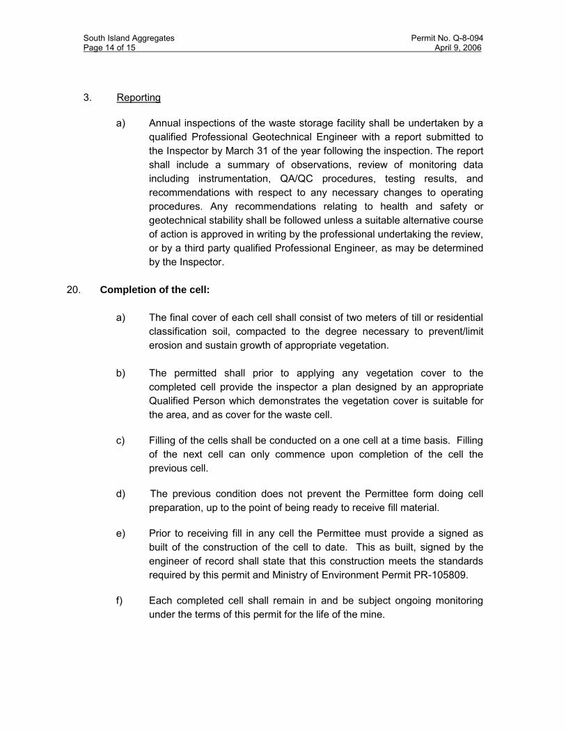
South Island Aggregates Permit No. Q-8-094 Page 14 of 15 April 9, 2006
3. Reporting
a) Annual inspections of the waste storage facility shall be undertaken by a qualified Professional Geotechnical Engineer with a report submitted to the Inspector by March 31 of the year following the inspection. The report shall include a summary of observations, review of monitoring data including instrumentation, QA/QC procedures, testing results, and recommendations with respect to any necessary changes to operating procedures. Any recommendations relating to health and safety or geotechnical stability shall be followed unless a suitable alternative course of action is approved in writing by the professional undertaking the review, or by a third party qualified Professional Engineer, as may be determined by the Inspector.
20. Completion of the cell:
a) The final cover of each cell shall consist of two meters of till or residential classification soil, compacted to the degree necessary to prevent/limit erosion and sustain growth of appropriate vegetation.
b) The permitted shall prior to applying any vegetation cover to the
completed cell provide the inspector a plan designed by an appropriate Qualified Person which demonstrates the vegetation cover is suitable for the area, and as cover for the waste cell.
c) Filling of the cells shall be conducted on a one cell at a time basis. Filling
of the next cell can only commence upon completion of the cell the previous cell.
d) The previous condition does not prevent the Permittee form doing cell
preparation, up to the point of being ready to receive fill material. e) Prior to receiving fill in any cell the Permittee must provide a signed as
built of the construction of the cell to date. This as built, signed by the engineer of record shall state that this construction meets the standards required by this permit and Ministry of Environment Permit PR-105809.
f) Each completed cell shall remain in and be subject ongoing monitoring
under the terms of this permit for the life of the mine.

South Island Aggregates Permit No. Q-8-094 Page 15 of 15 April 9, 2006
g) Once completed a cell shall not be disturbed unless work is necessary for maintenance or repair, and then only with the written approval of the Inspector.
h) The Manager shall, by March 31 of each year, provide the Inspector a
report identifying the volume of water treated through the treatment plant, and shall include all operating costs associated with the operation and maintenance of the treatment plant.
21. The Manager shall forward to the Inspector a copy of the report submitted to the
Minister of Finance in relation to the annual Health and Safety Assessment. This report provides a report stating the annual production.
22. Surface water not subject to treatment in the water treatment plant shall be monitored at the discharge point to the receiving environment and suspended solids shall not exceed 25mg/litre. In addition this monitoring shall include analysis for nitrates, and nitrate content shall not exceed the limits specified for drinking water.
23. Production from this quarry is limited to 240,000 tonnes annually.

APPENDIX B As-Builts

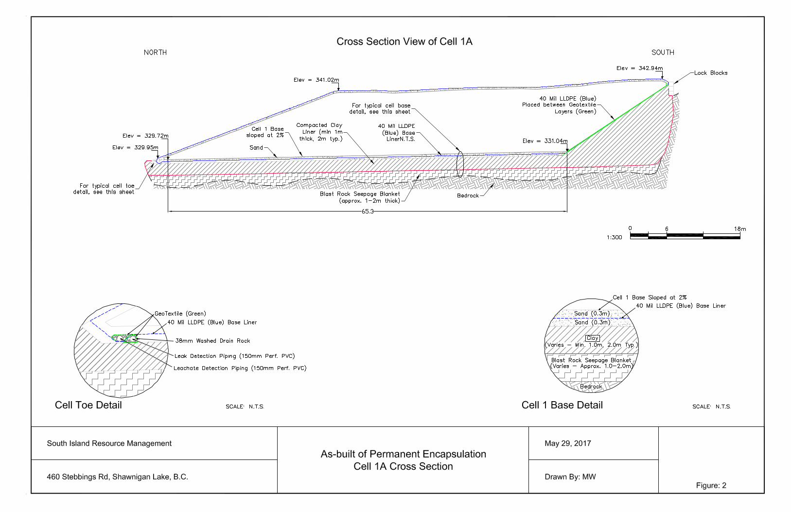


APPENDIX C Slide

HA SSOCIATES ANSENS PERLING
DRAWING NO:
CHECKED
DRAWN
DESIGNED
yyyy/mm/dd
PROJECT NO:DATE:SCALE:PROJECT: TITLE:
SECTION A-A’ StaticN/A 2017/05/27
IB
IB
TS
FIGURE C-1
Final Closure Plan17039Cobble Hill Holding
Ltd.

HA SSOCIATES ANSENS PERLING
DRAWING NO:
CHECKED
DRAWN
DESIGNED
yyyy/mm/dd
PROJECT NO:DATE:SCALE:PROJECT: TITLE:
SECTION B-B’ StaticN/A 2017/005/27
IB
IB
TS
FIGURE C-2
Final Closure Plan
17039Cobble Hill Holding Ltd.

HA SSOCIATES ANSENS PERLING
DRAWING NO:
CHECKED
DRAWN
DESIGNED
yyyy/mm/dd
PROJECT NO:DATE:SCALE:PROJECT: TITLE:
SECTION A-A’ SeismicN/A 2017/005/27
IB
IB
TS
FIGURE C-3
Final Closure Plan
17039Cobble Hill Holding Ltd.

HA SSOCIATES ANSENS PERLING
DRAWING NO:
CHECKED
DRAWN
DESIGNED
yyyy/mm/dd
PROJECT NO:DATE:SCALE:PROJECT: TITLE:
SECTION B-B’ SeismicN/A 2017/005/27
IB
IB
TS
FIGURE C-4
Final Closure Plan
17039Cobble Hill Holding Ltd.

HA SSOCIATES ANSENS PERLING
DRAWING NO:
CHECKED
DRAWN
DESIGNED
yyyy/mm/dd
PROJECT NO:DATE:SCALE:PROJECT: TITLE:
200 mm MoundingCircular Static
N/A 2017/005/27
IB
IB
TS
FIGURE C-5
Final Closure Plan
17039Cobble Hill Holding Ltd.
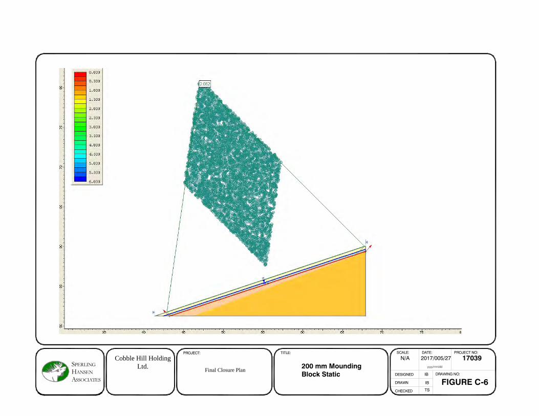
HA SSOCIATES ANSENS PERLING
DRAWING NO:
CHECKED
DRAWN
DESIGNED
yyyy/mm/dd
PROJECT NO:DATE:SCALE:PROJECT: TITLE:
200 mm MoundingBlock Static
N/A 2017/005/27
IB
IB
TS
FIGURE C-6
Final Closure Plan
17039Cobble Hill Holding Ltd.

HA SSOCIATES ANSENS PERLING
DRAWING NO:
CHECKED
DRAWN
DESIGNED
yyyy/mm/dd
PROJECT NO:DATE:SCALE:PROJECT: TITLE:
200 mm MoundingCircular Seismic
N/A 2017/005/27
IB
IB
TS
FIGURE C-7
Final Closure Plan
17039Cobble Hill Holding Ltd.

HA SSOCIATES ANSENS PERLING
DRAWING NO:
CHECKED
DRAWN
DESIGNED
yyyy/mm/dd
PROJECT NO:DATE:SCALE:PROJECT: TITLE:
200 mm Mounding Block Seismic
N/A 2017/005/27
IB
IB
TS
FIGURE C-8
Final Closure Plan
17039Cobble Hill Holding Ltd.
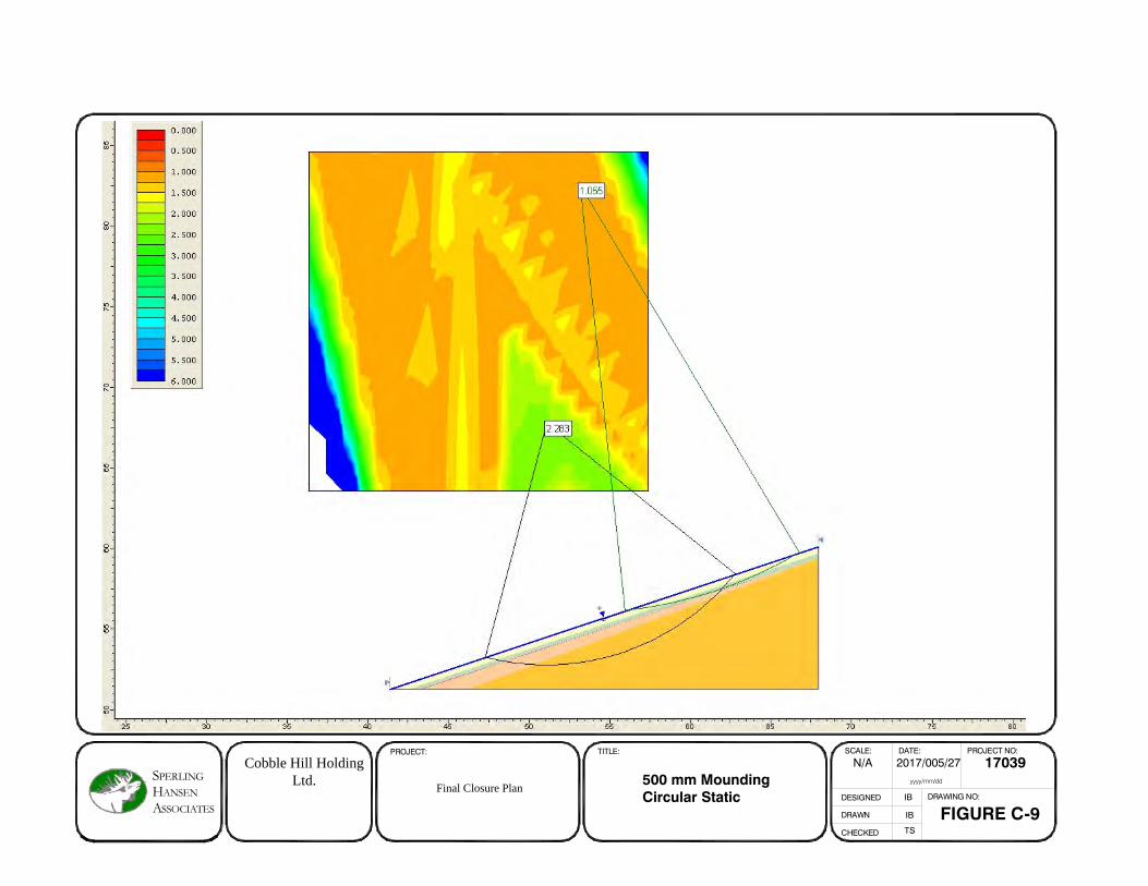
HA SSOCIATES ANSENS PERLING
DRAWING NO:
CHECKED
DRAWN
DESIGNED
yyyy/mm/dd
PROJECT NO:DATE:SCALE:PROJECT: TITLE:
500 mm MoundingCircular Static
N/A 2017/005/27
IB
IB
TS
FIGURE C-9
Final Closure Plan
17039Cobble Hill Holding Ltd.

HA SSOCIATES ANSENS PERLING
DRAWING NO:
CHECKED
DRAWN
DESIGNED
yyyy/mm/dd
PROJECT NO:DATE:SCALE:PROJECT: TITLE:
500 mm MoundingBlock Static
N/A 2017/005/27
IB
IB
TS
FIGURE C-10
Final Closure Plan
17039Cobble Hill Holding Ltd.

HA SSOCIATES ANSENS PERLING
DRAWING NO:
CHECKED
DRAWN
DESIGNED
yyyy/mm/dd
PROJECT NO:DATE:SCALE:PROJECT: TITLE:
500 mm MoundingCircular Seismic
N/A 2017/005/27
IB
IB
TS
FIGURE C-11
Final Closure Plan
17039Cobble Hill Holding Ltd.

HA SSOCIATES ANSENS PERLING
DRAWING NO:
CHECKED
DRAWN
DESIGNED
yyyy/mm/dd
PROJECT NO:DATE:SCALE:PROJECT: TITLE:
500 mm Mounding Block Seismic
N/A 2017/005/27
IB
IB
TS
FIGURE C-12
Final Closure Plan
17039Cobble Hill Holding Ltd.

APPENDIX D X-Sections for Slide

Profile View of Alignment A-A
310
320
330
340
350
360
310
320
330
340
350
360
0+02
0
0+04
0
0+06
0
0+08
0
0+10
0
0+12
0
0+12
5
320
310
330
340
320
350
0+
020
0+
040
0+
080
0+
060
0+
100
0+
120
SECTION A-A'
LEGEND:
CLIENT:
PROJECT:
TITLE:
SCALE:
DESIGNED
DRAWN
CHECKED
DRAWING NO:
SG
TS
DATE: PROJECT NO:
FIGURE D-1
COBBLE HILL LANDFILLFINAL CLOSURE PLAN
COBBLE HILL HOLDINGS LTD.
SECTION A-A'
1:500 2017/05/26 PRJ 17039yyyy/mm/dd
(604) 986-7734(604) 986-7723
North Vancouver, B.C. V7J 1J3#8 - 1225 East Keith Road
Environmental Monitoring
Design & Operations Plans
Landfill Services Group
Fax:Phone:
Landfill Closure
Landfill Siting
SSOCIATES
S PERLING ANSENHA
EXISTING GROUND
DESIGN SUBGRADE SURFACE
BASE LINER SURFACE
APPROXIMATE BEDROCKSURFACE
SEE APPENDIX B FOR
BASE LINER DETAILS
SEE FIGURE 4-2 FOR FINAL COVER
SYSTEM DETAILS

Profile View of Alignment B-B
320
330
340
350
360
320
330
340
350
360
0+02
0
0+04
0
0+06
0
0+08
0
0+10
0
0+12
0
0+13
1
0+
020
0+
040
0+
080
0+
060
0+
100
0+
120
0+
130
320
330
340
320
350
SECTION B-B'
LEGEND:
CLIENT:
PROJECT:
TITLE:
SCALE:
DESIGNED
DRAWN
CHECKED
DRAWING NO:
SG
TS
DATE: PROJECT NO:
FIGURE D-2
COBBLE HILL LANDFILLFINAL CLOSURE PLAN
COBBLE HILL HOLDINGS LTD.
SECTION B-B'
1:500 2017/05/31 PRJ 17039yyyy/mm/dd
(604) 986-7734(604) 986-7723
North Vancouver, B.C. V7J 1J3#8 - 1225 East Keith Road
Environmental Monitoring
Design & Operations Plans
Landfill Services Group
Fax:Phone:
Landfill Closure
Landfill Siting
SSOCIATES
S PERLING ANSENHA
EXISTING GROUND
DESIGN SUBGRADE SURFACE
BASE LINER SURFACE
APPROXIMATE BEDROCKSURFACE
SEE APPENDIX B FOR
BASE LINER DETAILS
SEE FIGURE 4-2 FOR FINAL COVER
SYSTEM DETAILS