rpmtag chapter 6 - dowel bar · pdf filechapter 6—dowel bar retrofit january 18, 2008...
TRANSCRIPT

MTAG Volume II - Rigid Pavement Preservation 2nd Edition Caltrans Division of Maintenance CHAPTER 6—DOWEL BAR RETROFIT January 18, 2008
6-1
Disclaimer
The contents of this guide reflect the views of the authors who are responsible for the facts and accuracy of the data presented herein. The contents do not necessarily reflect the official views or policies of the State of California or the Federal Highway Administration. This guide does not constitute a standard, specification, or regulation.
CHAPTER 6 DOWEL BAR RETROFIT This chapter describes a treatment technique for restoring load transfer efficiency through dowel bar retrofit. The material presented in this chapter has been taken largely from the FHWA/ACPA report “Concrete Rehabilitation – Guide to Load Transfer Restoration” (FHWA/ACPA, 1997) and the FHWA course notes from “Pavement Preservation Design and Construction of Quality Preventative Maintenance Treatments,” Module 3-5 – Load Transfer Restoration (FHWA, 2004). Other sources are cited as appropriate.
6.1 BACKGROUND In jointed plain concrete pavements (JPCP), load transfer refers to the ability of transferring load from one slab across a joint or crack to the adjacent slab as traffic passes over the joint. The transfer occurs through a shear action. The shear load is transferred by a combination of interlocking of aggregate in the adjacent slabs and mechanical action of dowel bars (or other load transfer devices) if they are present. Load transfer reduces stresses in the slab and also reduces deflections at the joint. Effective load transfer provides several benefits to rigid pavements:
• Slows or reduces development of pumping and faulting by reducing slab deflections. • Decreases cracking within the slab by reducing tensile stresses.
Dowel bar retrofit is a process commonly used to restore load transfer at JPCP joints.
6.1.1 Load Transfer Efficiency Load Transfer Efficiency (LTE) is the numerical measure used to define the effectiveness of load transfer. LTE may be defined either in terms of the stress transferred or the displacement transferred across slabs. The most common and generally recommended method is to base LTE on measurement of the deflections of slabs on either side of a crack or joint during wheel loadings using the formula:
100LTE ×∆∆
=L
U
(Eq. 6-1) where:
U∆ = Deflection on the unloaded side of the joint L∆ = Deflection on the loaded side of the joint
If there is perfect load transfer, both slabs will deflect equally and the LTE value will be equal to 100 percent. Conversely if there is no load transfer, the deflection of the unloaded slab will be zero and the LTE will be zero percent. A displacement LTE of 70 percent or higher is generally considered to be satisfactory. Figure 6-1 schematically portrays effective and ineffective load transfer.

MTAG Volume II - Rigid Pavement Preservation 2nd Edition Caltrans Division of Maintenance CHAPTER 6—DOWEL BAR RETROFIT January 18, 2008
6-2
Figure 6-1 Load transfer (Caltrans, 2006a)
6.1.2 Measuring Load Transfer Efficiency LTE measurements must be made with a device that can simulate heavy (truck) wheel loads. A Falling Weight Deflectometer (FWD) is commonly used to measure LTE as defined in Equation 6-1. Automated systems are available elsewhere that can measure and digitally record several miles of pavement per day depending on joint spacing (FHWA/NHI, 2004). LTE measurements can vary significantly as the temperature of the pavement slabs change. At high temperatures the thermal expansion of the slabs causes the joints to close, thus LTE is increased by aggregate interlock. It is important that FWD deflection testing is conducted in the morning hours when ambient air temperatures are less than 70°F (21°C). This is probably the best time for measuring deflections and determining LTEs because the joints should not be as “tight” as they will be when the temperature rises. LTE measurements should be made in the outer wheel paths which are subject to the highest truck loads.
6.2 PURPOSE AND DESCRIPTION OF TREATMENT Non-doweled, jointed plain concrete pavements (JPCP) depend on aggregate interlock to transfer load across joints. As these joints deteriorate through age and trafficking, aggregate interlock is lost and LTE decreases. Prior to 1998, Caltrans built concrete pavements without dowel bars and aggregate interlock was only method used to transfer load across joints. For doweled, jointed reinforced concrete pavements (JRCP), a similar loss in LTE can occur if existing dowel bars at the joints fail through corrosion, rupture, or deformation. Mid-panel transverse cracks of medium- to high severity generally have low LTE for both JPCP and JRCP. Load transfer restoration (LTR) is the process of improving LTE of jointed plain concrete pavements by placing “load transfer” devices at joints or cracks to aid in the transfer of stresses across the joints or cracks. Dowel bar retrofit (DBR) is a method of LTR which installs new dowel bars in existing rigid pavements. It has been successfully used to increase LTE at both slab joints and mid-panel transverse slab cracks in JPCP (FHWA, 1991; FHWA/ACPA, 1997; Pierce et al, 2003; Caltrans,

MTAG Volume II - Rigid Pavement Preservation 2nd Edition Caltrans Division of Maintenance CHAPTER 6—DOWEL BAR RETROFIT January 18, 2008
6-3
2002b). The process entails cutting slots across the existing slab joints or transverse cracks, installing dowel bars in these slots, and then backfilling the slots with a non-shrink grout material. When properly installed, dowel bar retrofits have been shown to significantly improve LTE and prolong pavement life by 10-15 years by reducing faulting and further deterioration of joints and cracks (FHWA, 1991; FHWA/ACPA, 1997; Pierce et al, 2003; Caltrans, 2002b). DBR is often combined with diamond grinding to reduce faulting and other surface irregularities. Caltrans has used this technique with success, although some projects were not properly carried out which resulted in less successful results.
6.3 PROJECT SELECTION Dowel bar retrofit (DBR) is best suited for pavements that are structurally sound, but exhibit low load transfer at joints and/or cracks. Pavements with little remaining structural life, as evidence by extensive cracking (more than 10% stage 3 cracking) or with high severity joint defects are not good candidates for DBR. Two typical cases where DBR can be effective are shown below (FHWA/ACPA, 1997):
• An aging but structurally sound pavement, with adequate thickness but exhibiting significant load transfer loss due to lack of dowels, poor aggregate interlock and/or erosion of base, subbase, or subgrade below slab.
• A relatively young pavement in good or better condition but with the potential to develop faulting, working cracks, or corner breaks due to insufficient slab thickness, joint spacing greater than 15 feet (4.6 m), or inadequate joint load transfer.
6.3.1 Factors to Consider There are five major factors to consider when evaluating a potential project for DBR:
• Structural condition of the slabs • Structural condition of the base • Measured LTE values • Magnitude of faulting • Condition of joints and/or cracks
Structural condition of the slabs: Pavements should be in good structural condition to be candidates for DBR. Pavement slabs exhibiting D-cracking, alkali-silica reaction (ASR) or alkali-carbonate reaction (ACR) distress, multiple transverse cracking, or significant longitudinal cracking are poor candidates for DBR. In these cases, slab replacement should be considered. If more than 10 percent of the pavement slabs exhibit such structural defects, it may be more cost effective to remove and replace the entire pavement surface course (FHWA, 1996). Structural condition of base: The pavement base should be in good structural condition to support the slabs. Slabs with a high deflection value at the joints are generally an indication of poor base condition. Measured LTE Values: Pavements with average LTE of less than 60 percent are generally candidates for DBR (FHWA/ACPA 1997). As long as the slabs are structurally sound, a lower limit for applicability of DBR has not been established. In fact, joints with LTE as low as 10 percent have seen significant improvement in LTE after DBR (Pierce et al, 2003) if the dowels are properly installed.
MTAG Volume II - Rigid Pavement Preservation 2nd Edition Caltrans Division of Maintenance CHAPTER 6—DOWEL BAR RETROFIT January 18, 2008
6-4
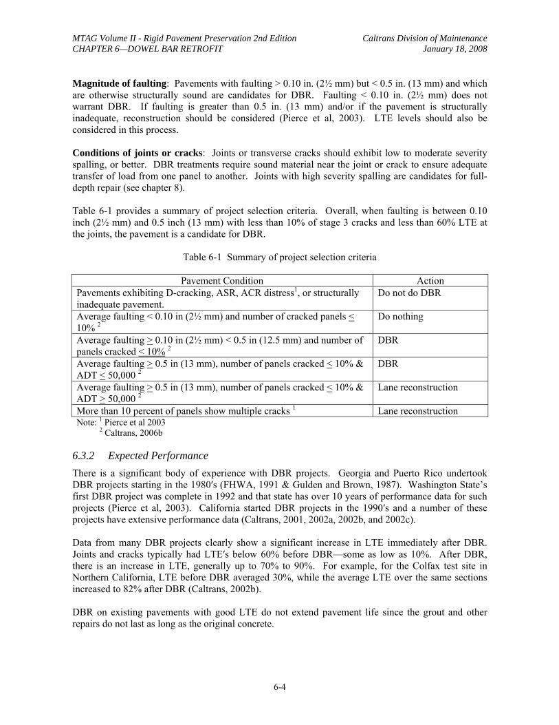
Magnitude of faulting: Pavements with faulting > 0.10 in. (2½ mm) but < 0.5 in. (13 mm) and which are otherwise structurally sound are candidates for DBR. Faulting < 0.10 in. (2½ mm) does not warrant DBR. If faulting is greater than 0.5 in. (13 mm) and/or if the pavement is structurally inadequate, reconstruction should be considered (Pierce et al, 2003). LTE levels should also be considered in this process. Conditions of joints or cracks: Joints or transverse cracks should exhibit low to moderate severity spalling, or better. DBR treatments require sound material near the joint or crack to ensure adequate transfer of load from one panel to another. Joints with high severity spalling are candidates for full-depth repair (see chapter 8). Table 6-1 provides a summary of project selection criteria. Overall, when faulting is between 0.10 inch (2½ mm) and 0.5 inch (13 mm) with less than 10% of stage 3 cracks and less than 60% LTE at the joints, the pavement is a candidate for DBR.
Table 6-1 Summary of project selection criteria
Pavement Condition Action Pavements exhibiting D-cracking, ASR, ACR distress1, or structurally inadequate pavement.
Do not do DBR
Average faulting < 0.10 in (2½ mm) and number of cracked panels < 10% 2
Do nothing
Average faulting > 0.10 in (2½ mm) < 0.5 in (12.5 mm) and number of panels cracked < 10% 2
DBR
Average faulting > 0.5 in (13 mm), number of panels cracked < 10% & ADT < 50,000 2
DBR
Average faulting > 0.5 in (13 mm), number of panels cracked < 10% & ADT > 50,000 2
Lane reconstruction
More than 10 percent of panels show multiple cracks 1 Lane reconstruction Note: 1 Pierce et al 2003 2 Caltrans, 2006b
6.3.2 Expected Performance There is a significant body of experience with DBR projects. Georgia and Puerto Rico undertook DBR projects starting in the 1980′s (FHWA, 1991 & Gulden and Brown, 1987). Washington State’s first DBR project was complete in 1992 and that state has over 10 years of performance data for such projects (Pierce et al, 2003). California started DBR projects in the 1990′s and a number of these projects have extensive performance data (Caltrans, 2001, 2002a, 2002b, and 2002c). Data from many DBR projects clearly show a significant increase in LTE immediately after DBR. Joints and cracks typically had LTE′s below 60% before DBR—some as low as 10%. After DBR, there is an increase in LTE, generally up to 70% to 90%. For example, for the Colfax test site in Northern California, LTE before DBR averaged 30%, while the average LTE over the same sections increased to 82% after DBR (Caltrans, 2002b). DBR on existing pavements with good LTE do not extend pavement life since the grout and other repairs do not last as long as the original concrete.

MTAG Volume II - Rigid Pavement Preservation 2nd Edition Caltrans Division of Maintenance CHAPTER 6—DOWEL BAR RETROFIT January 18, 2008
6-5
According to at least one source (Gulden and Brown, 1987), the improvement in LTE after DBR appears to extend over a period of up to 15 years. Data from Washington State projects (Pierce et al, 2003) indicates LTE for retrofitted sections remains above 70% for some ten years after DBR. In addition to improved LTE, the magnitude of faulting is less in retrofitted sections than in similar, untreated sections. Thus there appears to be a significant improvement in LTE and a similar decrease in the development of faulting over at a 10 to 15 year period for properly execute DBR projects. When properly installed, failure of DBR projects appears to be very low. A review of 7,000 dowel bars in Puerto Rico indicated that less than 0.5 percent failed (FHWA, 1991). A review of 13 DBR projects in 9 states indicated that only 2 percent of 515 properly installed dowel bars had failed (Gulden and Brown, 1987). However, Caltrans has experienced a number of DBR projects that failed to meet performance expectations (Caltrans, 2001, 2002a, 2002c). Typical problems include: bond failure between concrete and backfill material; spalling at joints; and a rough surface after backfilling. In all of these cases, the main cause of performance problems appears to be poor workmanship during construction and/or insufficient time to complete the DBR project using good workmanship and still allow enough curing time for the backfill material. The remaining sections of this chapter discuss how to properly design and execute a DBR project. Section 6.7 provides a troubleshooting guide based on lessons learned from both successful and unsuccessful DBR projects.
6.4 DESIGN AND MATERIAL CONSIDERATIONS
6.4.1 Load Transfer Devices Although a number of load transfer devices have been tested, the most effective load transfer device and the one recommended by FHWA is the smooth, round dowel bars (FHWA/ACPA, 1997). Smooth dowel bars effectively transfer shear loads across joints and cracks but allow for the longitudinal movement of the bars within the concrete slab. This allows for thermal expansion and contraction of slabs at the joints.
6.4.2 Dowel Bar Specifications A variety of dowel bars materials have been tested, including fiber reinforced plastic and stainless steel. Dowels should meet the following specifications. Material: Caltrans (2006b) specifies the following requirements for dowel bars to be used on dowel bar retrofit projects. Dowel bars must be plain, smooth, round, epoxy-coated steel conforming to the requirements in ASTM Designation: A 615 / A 615M, Grade 40 or 60. Epoxy coating of dowel bars must conform to the provisions in ASTM Designation: A 884 / A 884M, Class A, Type 1 or Type 2, except that the bend test shall not be apply. Dowel bars must be free from burrs or other deformations detrimental to free movement of the bars in the concrete. Dowels bars must be coated entirely with a bond breaker to allow longitudinal movement of bars after curing. Caltrans allows the following bond breaker materials (Caltrans, 2006b):
• Paraffin based lubricant shall be Dayton Superior DSC BB-Coat or Valvoline Tectyl 506 or an approved equal.
• White-pigmented curing compound in conformance with ASTM C 309, Type 2, Class A, and it shall contain 22% minimum nonvolatile compound consisting of at least 50% paraffin wax.

MTAG Volume II - Rigid Pavement Preservation 2nd Edition Caltrans Division of Maintenance CHAPTER 6—DOWEL BAR RETROFIT January 18, 2008
6-6
The compound shall be applied in 2 separate applications, with an application rate of approximately 1 gallon per 150 square feet (0.27 L/m2).
• Caltrans does not allow the use of oil- or asphalt-based bond breakers. Dimensions: Caltrans (2005) requires the use of dowel bars with a length of 18 inches (~ 460 mm). Recent research by the Minnesota DOT indicates that 15 inch (380 mm) dowels provide adequate LTE. A 1½ inch (~ 40 mm) diameter dowel bar should be used when the existing pavement thickness is equal to or greater than 0.70 ft (215 mm). For a pavement thickness less than 0.70 ft (215 mm), use a 1¼ inch (~ 30 mm) diameter dowel bar. Expansion Caps: Each end of the dowel bar must have a tight fitting, commercial quality, nonmetallic, non-organic material end cap that allows a minimum of ¼ inch (6 mm) of movement at each end of the bar (Caltrans, 2006b). Caulking Filler: Caulking filler used for sealing the transverse joint at the bottom and sides of the dowel bar slot must be a silicone caulk containing a minimum of 50% silicone and designated as a concrete sealant. Caulking filler must conform to the requirements of ASTM Designation: C 834 (Caltrans, 2006b). Foam Core Inserts: Each dowel bar must be fit with a foam core sheet that will be used to maintain the continuity of the joint or crack across the slot in which the dowel is placed. The foam core can be made of rigid styrofoam or closed cell foam material and faced with either poster board or a suitable plastic material. The insert shall be capable of remaining in a vertical position and tight to all edges during the placement of the fast setting grout (Caltrans, 2006b). Dowel Bar Support Chairs: Dowel bars must be fit with chairs that will firmly hold the dowels centered in the slots during fast setting grout backfilling operations and support the dowels a minimum of ½ inch (13 mm) from the bottom of the slot while the grout backfilling is placed and consolidated. Caltrans allows the following dowel bar support chairs (Caltrans, 2006b):
• Completely epoxy-coated steel conforming to the requirements of ASTM Designation: A 884 / A 884M.
• Commercial quality nonmetallic, non-organic material. Figure 6-2 shows a typical dowel bar used in a retrofit project, including the end caps, chair, and foam core insert.
Figure 6-2 Photo of dowels with chair, end caps, and foam core inserts in place (Caltrans, 2006a)

MTAG Volume II - Rigid Pavement Preservation 2nd Edition Caltrans Division of Maintenance CHAPTER 6—DOWEL BAR RETROFIT January 18, 2008
6-7
6.4.3 Dowel Bar Layout Number of Dowels: Early DBR projects installed 4 or 5 dowels in each wheelpath. However research indicates that 3 dowels per wheel path provides adequate LTE (Pierce et al, 2003). Dowel Location and Spacing: Spacing between dowels should be 12 inches (300 mm). For pavements with asphalt concrete or untied PCC shoulders, the outer most dowels should be no more than 12 inches (300 mm) from the slab edge. Figure 6-3 shows the Caltrans recommended dowel layout (Caltrans, 2005).
Figure 6-3 Dowel layout figure (Caltrans, 2005) Dowel Alignment and Tolerance: The load transfer performance of DBR is highly dependant on the final orientation of the dowels at the end of construction. Dowels should be placed horizontally, with their axis aligned with the pavement edge or longitudinal joint and the center of the dowel at the slab’s mid-depth. Caltrans specifies the following tolerances for dowel bar alignment (Caltrans, 2006b):
• The dowel bars must be placed to the depth shown on the plans, parallel to the traffic lane centerline and the top of the pavement surface, and the middle of the slot width within a tolerance of ¼ inch (6 mm).
• Dowel bars must be centered at the transverse joint, such that no less than 8 inches (200 mm) and no more than 10 inches (250 mm) of the dowel bar are extended into each adjacent panel.
Other recommended tolerances for alignment by Pierce et al (2003) are:

MTAG Volume II - Rigid Pavement Preservation 2nd Edition Caltrans Division of Maintenance CHAPTER 6—DOWEL BAR RETROFIT January 18, 2008
6-8
• Vertical o Location: ± 0.5 inch (13 mm ) of center of slab; o Skew from horizontal: ±0.5 inch (13 mm) over dowel bar length of 18 inches (460
mm)
• Longitudinal o Location: centered over joint ±0.5 inches (13 mm) o Embedment: 8 inches (200 mm) minimum on each end o Skew from parallel to pavement edge: ±0.5 inch (13 mm) over length of 18 inches
(460 mm) dowel
6.4.4 Backfill Material Material Selection: Selection of backfill material is critical to achieving long-term performance of DBR. Materials used must provide workability to allow adequate consolidation of material around the dowel bars and provide the early strength needed to allow the repaired area to be opened to traffic reasonably soon after completion of DBR. Generally materials suitable for partial depth repairs work well for DBR backfill. Jerzak (1994) provides the following material properties for backfill material (Table 6-2).
Table 6-2 Recommended backfill material properties (Jerzak, 1994)
Property Test Procedure Recommended Value Neat Material Compressive strength, 3 hr ASTM C 109 Minimum 3050 psi (21 MPa) Compressive strength, 24 hr ASTM C 109 Minimum 4930 psi (34 MPa) Abrasion loss, 24 hrs California Test 550 Max loss 0.06 lbs (25 g) Final Set Time Minimum 25 minutes Shrinkage, 4 days ASTM C 596 Maximum 0.13 percent Soluble Chlorides California Test 422 0.05 max Water Soluble Sulfates by mass, % California Test 417 0.25 max Maximum Extended Material Flexural Strength, 24 hr California Test 551 Minimum 495 psi (3.4 MPa) Bond to Dry PCC, 24 hr California Test551 Minimum 405 psi (2.8 MPa) Bond to SSD PCC, 24 hr California Test551 Minimum 305 psi (2.1 MPa) Absorption California Test551 Maximum 10 percent
In addition, the material should have a calculated durability factor of at least 90 percent after 300 freeze-thaw cycles per ASTM C 666. These recommendations are consistent with current Caltrans specifications for DBR backfill material (Caltrans Specification 40-015_A11-01-04). Caltrans DBR specifications allow backfill material to be (1) magnesium phosphate grout; (2) modified high alumina based grout; or (3) portland cement based grout. Backfill material must reach a minimum compressive strength of 2000 psi (13.8 MPa) before opening the pavement to traffic (FHWA/ACPA, 1997). The current industry trend is to use portland cement based material rather than proprietary rapid set materials. While the rapid set materials have worked well in many cases, a number of quality control problems have been encountered with them in the field. Among other field considerations, the shrinkage issue appears paramount. Portland cement

MTAG Volume II - Rigid Pavement Preservation 2nd Edition Caltrans Division of Maintenance CHAPTER 6—DOWEL BAR RETROFIT January 18, 2008
6-9
based materials provide more working time and are generally less risky under actual field conditions. Below is a brief description of the materials that may be considered for dowel bar backfill: Portland cement concrete: This material is readily available, less expensive than other materials, and does not create thermal compatibility issues. To achieve the early strengths needed to open a pavement relatively quickly, most mixes use Type III cement and an additional accelerator. This improves setting time and reduces shrinkage while still providing adequate working time. The backfill mixture is generally extended with sand and a coarse aggregate with a maximum size of 0.375 inches (9.5 mm). For pavements where traffic from studded tires or tire chains will occur, Washington State found it was important to include adequate coarse aggregates to prevent excessive surface wear (Pierce 2002).
Proprietary rapid set materials: Several proprietary materials such as Set 45 (magnesium phosphate-based), 5 Star Highway Patch, and AHT - DB Retrofit Mortar (Calcium aluminate-based) have also been used in DBR projects. The chief advantage of such materials is their quick setting time which can allow for an earlier opening of the repaired pavement. However, the same property limits for working time and can cause thermal compatibility problems. Material that has performed well in similar repairs may work well for DBR when used in accordance with manufacturer’s recommendations.
Polymer Concrete: Polymer concrete has also been used successfully as a backfill material. Methacrylate-based materials such as Concresive, Silikal, and Crylon are common examples. These materials consist of a liquid resin, filler material, and fine aggregate. They can achieve as much as 80 percent of their full strength in 2 hours or less, thus allowing for rapid opening of pavement to traffic. Their chief drawbacks are cost and required workmanship in a very short period of time.
Epoxy-Resin Materials: Epoxy resin materials have been used in concrete patch repairs and may be suitable for DBR backfill material. Water-based fiber reinforced materials are available. They can be extended with pea gravel. They have the same early strength advantage of polymer concrete and the same cost and workmanship disadvantages. Epoxy-resin material must meet ASTM C 881 requirements and the manufacturer’s guidance must be strictly followed by the contractor.
6.4.5 Design of Slot-Dowel-Chair System One of the most critical aspects affecting DBR performance is the final location of the dowel bars after placement of backfill material. The dowels must be placed precisely at the mid-depth of the slab, in a horizontal position, and along a line parallel to the edge or longitudinal joint of the pavement. Additionally dowels must be placed such that there is adequate space on all sides (½ inch [13 mm]) to allow backfill material to flow around the dowels during backfilling. In order to accomplish this, the slot, dowel, and chair must be designed as a complete system. The slot and chair shall be sized such that there is a snug fit when the dowel-chair system is placed in the slot. The chair shall be designed to rest on the saw kerfs at the edges of the slot rather than in the center of the slot where the concrete is rough due to the process of jack hammering out the concrete fin. The chair must be designed to provide adequate clearance between the base of the dowel and the base of the slot considering the raised area in the center of the slot where jack hammering fails to produce a perfectly flat surface (see Figure 6-4). The chair shall be designed to grip the dowel firmly such that the dowel is not dislodged from the chair during consolidation of the backfill material. Finally, the contractor shall be allowed sufficient time to complete as successful DBR project. The design and placement of the slot-dowel-chair system is critical to a successful DBR project.

MTAG Volume II - Rigid Pavement Preservation 2nd Edition Caltrans Division of Maintenance CHAPTER 6—DOWEL BAR RETROFIT January 18, 2008
6-10
Figure 6-4 Dowel/Slot layout (Caltrans, 2005)
6.4.6 Typical Item Codes Typical item codes for a dowel bar retrofit project are given in Table 6-3.
Table 6-3 Typical item codes for a dowel bar retrofit project
Item Code Description 074017 Prepare water pollution control program 074019 Prepare storm water pollution prevention plan 074020 Water pollution control 074042 Temporary concrete washout (portable) 120090 Construction area signs 120100 Traffic control system 128650 Portable changeable message sign 406100 Dowel bar retrofit 413111 Repair spalled joints 414101 Seal transverse joint 420201 Grind existing concrete pavement
Note: Standard special provisions and PS&E Guide must be referred for a specific item code proposed for the project.

MTAG Volume II - Rigid Pavement Preservation 2nd Edition Caltrans Division of Maintenance CHAPTER 6—DOWEL BAR RETROFIT January 18, 2008
6-11
Caltrans Standard Materials and Supplemental Work Item Codes can be found at the following web site:
http://i80.dot.ca.gov/hq/esc/oe/awards/#item_code
6.5 CONSTRUCTION PROCESS
6.5.1 Traffic Control and Safety The traffic control plan for a dowel bar retrofit project shall be prepared in accordance with the Caltrans Safety Manual and the Caltrans Code of Safe Operating Practices. The signs and devices used must match the traffic control plan. The work zone must conform to Caltrans standard practice and the requirements set forth in the Caltrans Safety Manual and the Caltrans Code of Safe Operating Practices and any other pertinent requirements. Each worker must be fully equipped with the required safety equipment and clothing. Signage shall be removed in a timely fashion when it no longer applies. Depending on project location, size, and amount of work, one of the following types of traffic control alternatives may be considered:
• Complete roadbed closure • Continuous lane closure • Weekend closure • Nighttime closure
Details on traffic control may be found in the Caltrans Traffic Manual (Caltrans, 1996) or at the website: http://www.dot.ca.gov/hq/traffops/signtech/signdel/trafficmanual.htm.
6.5.2 Dowel Bar Retrofit Process The DBR process contains the following steps:
• Cutting sides of slot • Remove concrete from slot • Sandblast and clean slot • Seal joint or crack where it intersects the slot • Place and align dowel bar • Place backfill material • Allow proper cure • Diamond grinding (optional) • Seal joint or crack
Figure 6-5 shows schematics of the construction process.

MTAG Volume II - Rigid Pavement Preservation 2nd Edition Caltrans Division of Maintenance CHAPTER 6—DOWEL BAR RETROFIT January 18, 2008
6-12
Figure 6-5 Schematics of the construction process (FHWA/ACPA, 1997)
6.5.3 Cutting Sides of Slot Slot cutting should be done using a diamond saw slot cutter. Modified milling machines have been used on some project to cut the slots. However, this practice is not recommended because milling machines cannot cut slots within the required tolerances for accurate dowel bar placement and an additional concern that microcracking around the slot area often occurs. Slot cutting machines where the blades are ganged together on a single arbor are essential to producing accurate slots that are parallel to the pavement edge or longitudinal joint. Ganged slot cutting machines are able to cut 6 to 8 slots simultaneously (covering 3 or 4 dowel bars per wheel path) are
DEPTH REQUIRED TO POSITION DOWEL BAR AT MID-DEPTH OF SLAB
BACKFILL MATERIAL
EXPANSION END CAP

MTAG Volume II - Rigid Pavement Preservation 2nd Edition Caltrans Division of Maintenance CHAPTER 6—DOWEL BAR RETROFIT January 18, 2008
6-13
currently available and commonly used (see Figure 6-6). To ensure that the slots are cut parallel to the pavement edge or longitudinal joint, it is essential that the slot cutting machine is carefully aligned with the pavement edge or longitudinal joint. This is true regardless of the orientation of the joint or crack. Figure 6-7 shows a set of well aligned slots cut for a three dowel bar / wheelpath installation.
Figure 6-6 Slot cutting machine with close-up of ganged cutter heads (Caltrans, 2006a)
Figure 6-7 Three pairs of slots cut in a single pass by a ganged slot cutting machine (Caltrans, 2006a) Slots must also be cut to a sufficient depth that the dowel will be centered at the mid-depth of the slab when the dowel-chair assembly is placed at the bottom of the slot. The width of the slot and the width of the chair must be carefully matched so that the dowel-chair assembly fits snugly into the slot, ensuring accurate alignment of the dowel within the slot. Slots are typically cut some 2½ inches (65 mm) wide. The slots must also be cut long enough so that a ½ inch (13 mm) clearance is maintained between the bottom of the dowel bar and the bottom of the slot along the entire length of the bar. It is important to consider the curvature of the saw blade when determining the actual required surface length for the slots (see Figure 6-8).

MTAG Volume II - Rigid Pavement Preservation 2nd Edition Caltrans Division of Maintenance CHAPTER 6—DOWEL BAR RETROFIT January 18, 2008
6-14
Figure 6-8 Details of chair-dowel system in slot
6.5.4 Remove Concrete from Slot Once the sides of the slot have been cut, the concrete fin remaining between the sides is removed. Care must be taken during this step not to damage the slot. The material surrounding the slot must not be cracked or damaged while removing the fin. For this reason, the fin material must be removed with a lightweight jackhammer (less than 30 lbs [14 kg]) and hand tools. Best results are achieved when the hammer is maintained at an angle of 45 degrees or shallower, especially when removing material from the bottom of the fin. This decreases the probability of the hammer punching through the bottom of the slot. Figure 6-9 shows jack hammering of the concrete fin.
Figure 6-9 Jack hammering (Caltrans, 2006a)
Chairs designed to rest onsaw kerfs at bottom of slot
and fit snugly in slot
Chairs must provide 0.5 in. (13 mm) above bottom of slot allowing for roughness of jack hammered surface
Dowel BarChair
Chair extends above dowelcenterline and holds dowel
firmly in place
Saw Kerfs

MTAG Volume II - Rigid Pavement Preservation 2nd Edition Caltrans Division of Maintenance CHAPTER 6—DOWEL BAR RETROFIT January 18, 2008
6-15
After removal of large pieces by jack hammering, the bottom of the slot must be flattened using a small toothed flat hammerhead. The bottom needs not to be perfectly smooth, but it must be flat enough that there is adequate clearance between the bottom of the dowel and the bottom of the slot. After the fin material is removed and the bottom of the slot flattened, the slots must be thoroughly sandblasted. This process removes dust from saw cutting and hammering operations and provides a clean surface for backfill material to properly bond to. Finally, the slot is air blasted or vacuumed to remove any remaining loose material. Sandblasting and air blasting equipment must have oil/water traps to prevent contamination of the slot. High pressure water blasting has also been successfully used to clean slots. If water blasting is used, all standing and surface water must be removed from the slot before dowel placement. Figure 6-10 shows sandblasting of the slot.
Figure 6-10 Sandblasting (Caltrans, 2006a) In addition to cleaning the slots, the pavement surface in the immediate vicinity of the slots should be clean and free of dirt and debris that might otherwise be blown or knocked into the prepared slot, thereby contaminating the otherwise well-prepared slot. It is important to keep the repair area extremely clean and dry. If debris or dust is present in the repair area, an additional cleaning is mandatory.
6.5.5 Seal Joint or Crack Any joint or crack that intersects the slot must be properly sealed. Sealing the crack or joint is necessary to prevent the backfill material from entering the joint. If backfill material enters the joint, this can result in spalling of the new joint. The entire length of the slot must be sealed: down both sides of the slot and at the bottom. Ensure that the caulking material completely seals the joint or crack but does not contaminate the sides or bottom of the slot itself. Figure 6-11 shows a properly sealed joint.

MTAG Volume II - Rigid Pavement Preservation 2nd Edition Caltrans Division of Maintenance CHAPTER 6—DOWEL BAR RETROFIT January 18, 2008
6-16
Figure 6-11 Sealing joint/crack (Caltrans, 2006a)
6.5.6 Placing Dowel Bars Dowel bar preparation: Inspect all dowel bars for damaged epoxy coating and reject any dowels with chipped or damaged epoxy. Dowels must be coated with a bond breaker. If a factory bond breaker is applied, ensure that the entire bar remains coated; re-treat as needed. Do not apply bond breaker anywhere near the slots. Any contamination of the slots with bond breaker will cause failure of the backfill material. A plastic cap should be placed on each end of the dowel bar in a manner allowing at least ¼ inch (6 mm) of free space between the dowel end and outside of cap. The foam core insert and chairs should be placed on the dowels. Dowel bar placement: Each prepared dowel bar must be centered horizontally in the slot and rest on the chairs in a horizontal position. If the slot has been properly sized and prepared, the dowel bar must be aligned vertically at the mid-depth of the slab and have a clearance of at least ½ inch (13 mm) between the bottom of the dowel bar and the bottom of the slot. If the dowel bar, chair, and slot have all been properly designed and constructed, the dowel-chair system should fit snugly within the slot and help restrain the dowel during backfilling operations. Dowel bar alignment: The dowel bars must be placed within the slot such that they meet the tolerances specified in section 6.4.3. If the slot-dowel-chair system has been properly designed and the properly prepared, it should be a simple process of ensuring that the dowel-chair system is placed properly at the bottom of the slot. Attention must also be paid to the foam core insert to ensure that it is properly aligned with the joint or crack. Figure 6-12 shows placement of dowel bar in the slot.

MTAG Volume II - Rigid Pavement Preservation 2nd Edition Caltrans Division of Maintenance CHAPTER 6—DOWEL BAR RETROFIT January 18, 2008
6-17
Figure 6-12 Placing dowel-chair assembly (Caltrans, 2006a)
6.5.7 Backfilling Backfill material must be prepared and placed according to the manufacturer’s recommendations. It must be prepared in small enough batches such that all of the material from a single batch can easily be placed before the material stiffens to the point that it is not workable. No additional water is allowed to be added to the material once the proper mixture has been prepared. If the material stiffens to the point that it cannot be properly placed, it should be discarded and a new batch must be prepared. The vital elements to properly placing backfill material are: 1) place the material such that it does not disturb the dowel bar or the foam core insert, and 2) consolidate the material so it flows around the dowel and fills the entire slot including voids under and beside the dowel. The backfill must not be “dumped” into the slots, as this provides the greatest likelihood of disturbing either the dowel bar or the foam core insert. Instead, the backfill must be placed on a clean area of pavement next to the slot and then carefully shoveled into the slot. The slot must be uniformly filled on both sides of the joint or crack in order to keep the foam core insert aligned with the joint or crack. Figure 6-13 shows the placement of backfill material.

MTAG Volume II - Rigid Pavement Preservation 2nd Edition Caltrans Division of Maintenance CHAPTER 6—DOWEL BAR RETROFIT January 18, 2008
6-18
Figure 6-13 Placing backfill (Caltrans, 2006a) Backfill material must be consolidated with a small spud vibrator (less than one inch [25 mm] in diameter). Do not to allow the vibrator to hit the dowel bar as that may cause the dowel to become misaligned. The backfill material must not be overworked as this can cause migration of fines and water to the surface of the backfill material and weaken it. Figure 6-14 shows the consolidation of backfill material.
Figure 6-14 Consolidating backfill (Caltrans, 2006a) Backfill material must not be finished in a manner that tends to pull the material away from the sides of the slot. Instead, finishing operations must be done from the center of the slot toward the edges. If diamond grinding is to be done after the backfill material sets, the backfill should be finished 0.125 to 0.25 inches (3 to 6 mm) above the pavement surface. Immediately after finishing, the backfill material must be coated with curing compound or in accordance with the manufacturer’s recommendations.

MTAG Volume II - Rigid Pavement Preservation 2nd Edition Caltrans Division of Maintenance CHAPTER 6—DOWEL BAR RETROFIT January 18, 2008
6-19
6.5.8 Opening to Traffic The retrofitted pavement can be opened to traffic as soon as the backfill material has reached adequate strength—but not before! The minimum required compressive strength required to allow traffic on a repair is 2,000 psi (13.8 MPa) for slabs 8 in (200 mm) or thicker (FHWA/ACPA, 1997).
6.5.9 Diamond Grinding Caltrans (2006b) specifies that retrofit pavement lanes must be ground, conforming to the smoothness and finishing provisions in Section 42, “Groove and Grind Pavement” of the Caltrans Standard Specifications and Special Provisions 40-015. Diamond grinding can significantly improve ride quality by eliminating existing faulting and elevations between the backfill material and the pavement as well as undulations or rough spots that result from DBR construction. Diamond grinding should be completed within 30 days from the initial saw cutting for the dowel bar slots, since joint sealing cannot be completed until diamond grinding is done. Leaving the pavement with unsealed joints for an extended period of time is not advisable. All fast setting grout backfilled into the dowel slots shall have a minimum cure time of 12 hours before grinding (Caltrans, 2006b).
6.5.10 Joint Sealing Transverse joints should be sealed as soon as possible after backfill material placement and diamond grinding. A low modulus silicone joint sealer should be used. Chapter 4 of this guide provides a detail description on the joint sealing.
6.5.11 Job Review-Quality Control Ensuring a satisfactory DBR project requires a quality process throughout the project. The quality control process must start at the very beginning of project scoping and continue through project construction. The material presented below has been taken largely from an FHWA–NHI course material (FHWA/NHI, 2004). Project, Document, and Plan Reviews Prior to start of the project, conditions at the proposed project site should be reviewed to ensure that the project still meets the criteria outlined in section 6.3. In particular, the project should be checked for structural or any additional deterioration that may make DBR an inappropriate treatment. The following documents should be reviewed and any problems or required changes should be reconciled:
• Bid/project specifications and drawings • Special provisions • Traffic control plan • Manufacturer’s installation instructions for backfill material(s) • Material safety data sheets (MSDS) • Agency application requirements
Plan review includes a review of the slot-dowel-chair system. This review should also check the proposed slot cutting equipment, dowel bar, and chair design to ensure that the system allows accurate placement of dowel bars in accordance with project specifications (see section 6.4.5).

MTAG Volume II - Rigid Pavement Preservation 2nd Edition Caltrans Division of Maintenance CHAPTER 6—DOWEL BAR RETROFIT January 18, 2008
6-20
Preconstruction Reviews Material Review—the following material related items should be checked:
• Proposed backfill material o meets specifications o comes from an approved and qualified source o has been sampled and tested o packaging is not damaged (leaking, torn, or pierced)
• Caulking filler meets specifications • Dowel bars, chairs, foam core inserts, and end caps meet specifications • Curing compound meets specifications • Joint sealant material meets specifications • Logistics planning will ensure a supply of sufficient quantities of materials when needed
Equipment—prior to the start of the construction, all equipment should be inspected including:
• Slot saw—sufficient size and horse power to simultaneously cut all required slots in one wheel path
• Jackhammers—lightweight, less than 30 lbs (14 kg), which have proper heads for both fin removal and smoothing of the slot bottom
• Sand blasters—adjusted for correct sand rate; contains moisture and oil traps • Air compressors—sufficient volume and pressure to remove all debris and dust from slots • Auger type mixing equipment—free from material buildup and properly sized • Volumetric mixing equipment: Calibrated and in good condition (CT 109 certified) • Miscellaneous testing equipment—slump cone, air meter, cylinder molds w/lids, rod, mallet,
ruler, and 10 ft (3 m ) straightedge, available and functional • Vibrators—correct size (1 inch [25 mm] in diameter or less) and operating correctly
Weather requirements: Ensure that the weather conditions at the time of construction are within acceptable limits. The following conditions are recommended:
• Air and surface temperature suitable for concrete placement (typically above 40° F [4° C]) • Review manufacturer’s climate requirements for backfill material and placement • Do not remove existing concrete from slot if rain is predicted
Traffic Control: All traffic control devices should comply with Federal Manual on Uniform Traffic Control Devices and the California Supplement to the FMUTCD. Verify that devices in-place correspond to requirements of the approved traffic control plan. Construction Inspection Slot cutting: The following areas should be inspected during slot cutting:
• Slot cutter is lined up parallel to pavement edge or longitudinal joint before start of cutting operations
• Slots are parallel to each other and the pavement edge or longitudinal joint • Correct number of slots are cut • Slot alignment is adjusted to miss any existing longitudinal cracks
MTAG Volume II - Rigid Pavement Preservation 2nd Edition Caltrans Division of Maintenance CHAPTER 6—DOWEL BAR RETROFIT January 18, 2008
6-21
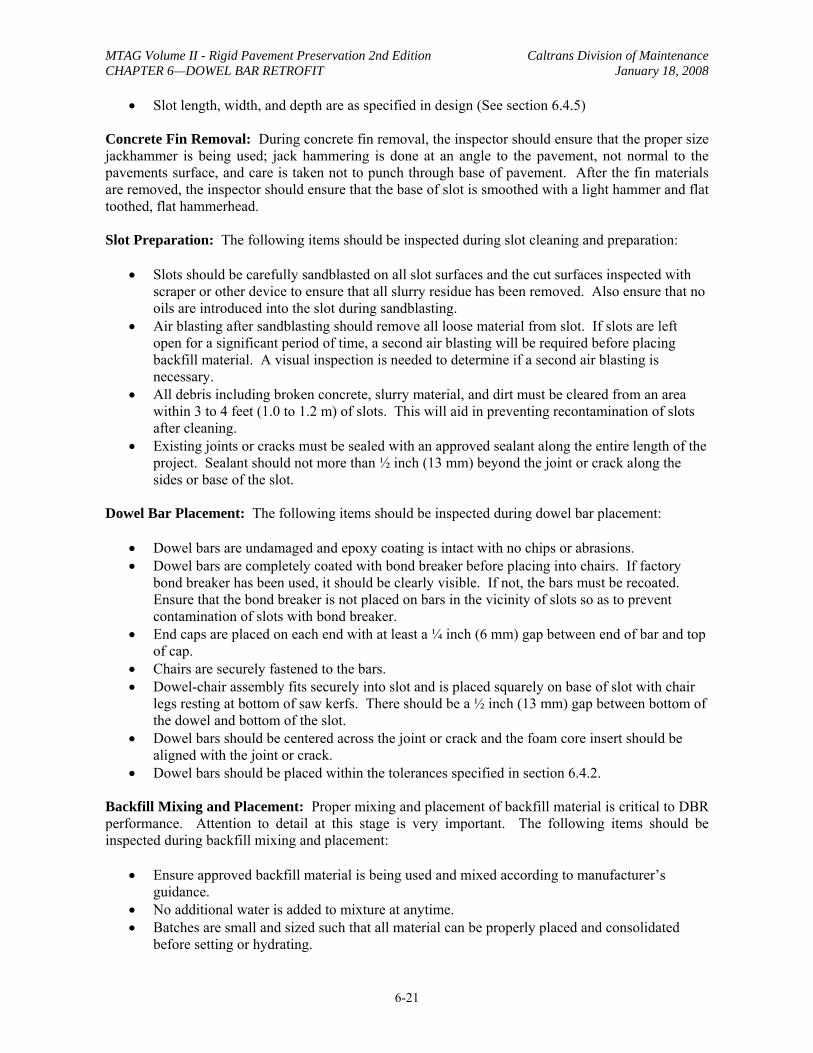
• Slot length, width, and depth are as specified in design (See section 6.4.5) Concrete Fin Removal: During concrete fin removal, the inspector should ensure that the proper size jackhammer is being used; jack hammering is done at an angle to the pavement, not normal to the pavements surface, and care is taken not to punch through base of pavement. After the fin materials are removed, the inspector should ensure that the base of slot is smoothed with a light hammer and flat toothed, flat hammerhead. Slot Preparation: The following items should be inspected during slot cleaning and preparation:
• Slots should be carefully sandblasted on all slot surfaces and the cut surfaces inspected with scraper or other device to ensure that all slurry residue has been removed. Also ensure that no oils are introduced into the slot during sandblasting.
• Air blasting after sandblasting should remove all loose material from slot. If slots are left open for a significant period of time, a second air blasting will be required before placing backfill material. A visual inspection is needed to determine if a second air blasting is necessary.
• All debris including broken concrete, slurry material, and dirt must be cleared from an area within 3 to 4 feet (1.0 to 1.2 m) of slots. This will aid in preventing recontamination of slots after cleaning.
• Existing joints or cracks must be sealed with an approved sealant along the entire length of the project. Sealant should not more than ½ inch (13 mm) beyond the joint or crack along the sides or base of the slot.
Dowel Bar Placement: The following items should be inspected during dowel bar placement:
• Dowel bars are undamaged and epoxy coating is intact with no chips or abrasions. • Dowel bars are completely coated with bond breaker before placing into chairs. If factory
bond breaker has been used, it should be clearly visible. If not, the bars must be recoated. Ensure that the bond breaker is not placed on bars in the vicinity of slots so as to prevent contamination of slots with bond breaker.
• End caps are placed on each end with at least a ¼ inch (6 mm) gap between end of bar and top of cap.
• Chairs are securely fastened to the bars. • Dowel-chair assembly fits securely into slot and is placed squarely on base of slot with chair
legs resting at bottom of saw kerfs. There should be a ½ inch (13 mm) gap between bottom of the dowel and bottom of the slot.
• Dowel bars should be centered across the joint or crack and the foam core insert should be aligned with the joint or crack.
• Dowel bars should be placed within the tolerances specified in section 6.4.2. Backfill Mixing and Placement: Proper mixing and placement of backfill material is critical to DBR performance. Attention to detail at this stage is very important. The following items should be inspected during backfill mixing and placement:
• Ensure approved backfill material is being used and mixed according to manufacturer’s guidance.
• No additional water is added to mixture at anytime. • Batches are small and sized such that all material can be properly placed and consolidated
before setting or hydrating.
MTAG Volume II - Rigid Pavement Preservation 2nd Edition Caltrans Division of Maintenance CHAPTER 6—DOWEL BAR RETROFIT January 18, 2008
6-22
• All slot surfaces are clean and dry. • Backfill is consolidated with a properly sized vibrator. The vibrator should not touch the
dowel bar and the material should not be over consolidated. It should require only 2 to 4 quick insertions of the vibrator into the material to properly consolidate it.
• Backfill material is finished with an outward motion ensuring material remains in contact with slot sides. Material should be finished 0.125 to 0.25 in. (3 to 6 mm) above pavement surface.
• Approved curing compound is applied to backfill material immediately after finishing or cured in accordance with the manufacturer’s recommendations.
Cleanup: After completion of DBR, all loose concrete is removed and disposed of according to project specifications. Any loose debris should also be removed. All mixing equipment should be cleaned up before the backfill material sets.
6.6 PROJECT CHECKLIST AND TROUBLESHOOTING GUIDE
6.6.1 Factors to Consider For a successful DBR project, slots must be properly cut in the pavement, dowel bars placed in proper alignment with adequate clearance on sides and bottom, and backfill material placed and properly consolidated without disturbing the dowel bars. Most DBR problems can be traced to one of two root causes: 1) poorly designed slot-dowel-chair system and/or 2) poor workmanship or quality control during construction. The importance of quality construction practices cannot be underestimated. It is essential that the contractors who are responsible for QC be familiar with the DBR process and knowledgeable of common problems and ways to avoid these problems.
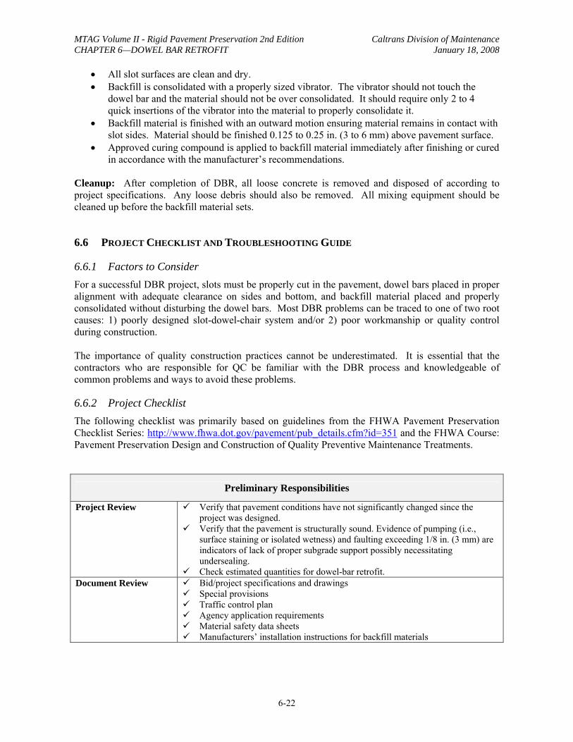
6.6.2 Project Checklist The following checklist was primarily based on guidelines from the FHWA Pavement Preservation Checklist Series: http://www.fhwa.dot.gov/pavement/pub_details.cfm?id=351 and the FHWA Course: Pavement Preservation Design and Construction of Quality Preventive Maintenance Treatments.
Preliminary Responsibilities Project Review Verify that pavement conditions have not significantly changed since the
project was designed. Verify that the pavement is structurally sound. Evidence of pumping (i.e.,
surface staining or isolated wetness) and faulting exceeding 1/8 in. (3 mm) are indicators of lack of proper subgrade support possibly necessitating undersealing.
Check estimated quantities for dowel-bar retrofit. Document Review Bid/project specifications and drawings
Special provisions Traffic control plan Agency application requirements Material safety data sheets Manufacturers’ installation instructions for backfill materials

MTAG Volume II - Rigid Pavement Preservation 2nd Edition Caltrans Division of Maintenance CHAPTER 6—DOWEL BAR RETROFIT January 18, 2008
6-23
Materials Checks
Cementing grout Verify that dowel slot backfill material meets specification requirements. Verify that dowel slot backfill material is being obtained from an approved
source as required by the specification. Verify that the component materials for the dowel slot backfill have been
sampled, tested, and approved prior to installation as required by contract documents.
Dowel bars Verify that dowels, dowel bar chairs, and end caps meet specification requirements.
Verify that dowel bars are properly coated with epoxy (or other approved material) and free of any minor surface damage in accordance with contract documents.
Joint/crack materials Verify that joint/crack re-former material (compressible insert) meets specification requirements (typically polystyrene foam board, 1/2 in.[12 mm] thick).
Verify that joint sealant material meets specification requirements. Other materials Verify that additional or extender aggregates have been properly produced,
with acceptable quality. Verify that material packaging is not damaged so as to prevent proper use
(packages leaking, torn, or pierced). Verify that caulking filler meets specification requirements. Verify that curing compound when required meets specification requirements.
General Verify that all required materials are on hand in sufficient quantities to complete the project.
Ensure that all material certifications required by contract documents have been provided to the agency prior to construction.
Equipment Inspections
Slot Cutting Equipment Verify that slot sawing machine is of sufficient weight, horsepower, and configuration to cut the specified number of slots per wheelpath to the depth shown on the plans.
Verify that removal jackhammers are limited to a maximum rated weight of 30 lb (14 kg).
Slot Cleaning and Preparation
Verify that sand blaster unit is adjusted for correct sand rate and that it is equipped with and using oil and moisture filters/traps.
Verify that air compressors have sufficient pressure and volume to adequately remove all dust and debris from slots and meet agency requirements.
Mixing and Testing Equipment
For auger-type mixing equipment, ensure that auger flights or paddles are kept free of material buildup, which can cause inefficient mixing operations.
Ensure that volumetric mixing equipment, such as mobile mixers, is kept in good condition and is calibrated (CT 109) on a regular basis to properly proportion mixes.
Ensure that material test equipment required by the specifications are all available on site and in proper working condition (typically including slump cone, pressure-type air meter, cylinder molds and lids, rod, mallet, ruler, and 10 ft (3 m) straightedge).
Other Equipment Verify that vibrators are the size specified in the contract documents (typically 1 in. [25 mm] in diameter or less) and are operating correctly.
Verify that the concrete testing technician meets the requirements of the contract document for training/certification.
Ensure that sufficient storage area is available on the project site specifically designated for the storage of concrete cylinders.

MTAG Volume II - Rigid Pavement Preservation 2nd Edition Caltrans Division of Maintenance CHAPTER 6—DOWEL BAR RETROFIT January 18, 2008
6-24
Others
Weather Requirements Review manufacturer installation instructions for requirements specific to the backfill material used.
Air and surface temperature meet agency requirements (typically 40 °F [4 °C] and rising) for concrete placement.
Dowel bar installation should not proceed if rain is imminent. Traffic Control Verify that the signs and devices used match the traffic control plan presented
in the contract documents. Verify that the setup complies with the Federal Manual on Uniform Traffic
Control Devices or local agency procedures. Verify that flaggers are trained and qualified according to contract documents
and agency requirements. Verify that unsafe conditions, if any, are reported to a supervisor. Ensure that traffic is not opened to the repaired pavement until the backfill
material has attained the specified strength or curing time as required by the contract documents.
Verify that signs are removed or covered when they are no longer needed.
Project Inspection Responsibilities Slot Cutting and Removal
Verify that all slots are cut parallel to each other and to the centerline of the roadway within the maximum tolerance permitted by the contract documents, typically 1/4 in. (6 mm) per 12 in. (300 mm) of dowel bar length.
Verify that the number of slots per wheelpath is in agreement with contract documents (typically three or four).
Verify that the cut slot length extends the proper distance each side of the construction joint as required by the contract documents. This is especially important for joints and cracks that are skewed.
Verify that concrete fins between the saw cuts are removed using 30 lb (14 kg) maximum weight jackhammers.
Verify that the bottoms of slots are smoothed and leveled using lightweight bush hammer.
Slot Cleaning and Preparation
Verify that after concrete removal, slots are prepared by sandblasting, ensuring that all saw slurry is removed from the slot.
Verify that air blasting is utilized to clean slots. A second air blasting may be required immediately before placement of dowel slot cementing grout if slots are left open for a duration exceeding that permitted in the contract documents.
Verify that the existing joint/crack is sealed with approved caulking filler along the bottom and sides of slot to prevent concrete patch material from entering the joint/crack.
Placement of Dowel Bars
Verify that plastic end caps are placed on each end of the dowel bar to account for pavement expansion as required by the contract documents.
Verify that dowels have been coated with lubricant to prevent bonding of concrete patch material to dowels in accordance with contract documents.
Verify that proper clearance is maintained between the supported dowel bar and the sidewalls, ends, and bottom of the cut slot in accordance with contract documents.
Schematic diagrams are intended for reference purposes only and are not intended to supersede contract documents.
Verify that chairs are used to align the dowel correctly in the slot and support it, and permit dowel slot backfill material to completely encapsulate the dowel bar.
Verify that joint re-former material (foam core insert) is placed at the mid-point of each bar and in line with the joint/crack to allow for expansion and to re-form the joint/crack.

MTAG Volume II - Rigid Pavement Preservation 2nd Edition Caltrans Division of Maintenance CHAPTER 6—DOWEL BAR RETROFIT January 18, 2008
6-25
Verify that dowel bars are centered across the joint/crack such that the minimum embedment of the dowel bar on each side of the joint is in accordance with contract documents.
Mixing, Placing, Finishing, and Curing Backfill Material
Verify that quantities of concrete patch material being mixed are small enough to prevent premature set.
Verify that material is consolidated using small, hand-held vibrators that do not touch the dowel bar assembly during consolidation.
Verify that concrete patch material is finished flush with surrounding concrete, using an outward motion to prevent pulling material away from patch boundaries. The surface of the concrete patch material should be finished slightly “humped” if diamond grinding will be done.
Verify that adequate curing compound is applied immediately following finishing and texturing in accordance with contract documents and manufacturer’s recommendations.
Cleanup Remove all concrete pieces and loose debris from the pavement surface. Dispose of old concrete in accordance with contract documents. Properly clean mixing, placement, and finishing equipment for the next use.
Diamond Grinding Diamond grinding of the pavement surface should be completed within 30 days of placement of the concrete patch material.
Resealing Joints and Cracks
Verify that joints are resealed after diamond grinding in accordance with contract documents.
6.6.3 Troubleshooting Guide The following guide provides a summary of possible problems, typical causes and potential solutions. The guide was primarily based on guidelines from the FHWA Pavement Preservation Checklist Series (http://www.fhwa.dot.gov/pavement/pub_details.cfm?id=351) and the FHWA Course: Pavement Preservation Design and Construction of Quality Preventive Maintenance Treatments.
Problem Causes and solutions Slots are not parallel to pavement edge or longitudinal joint
Cause: • Slot cutting machine not properly aligned. Solutions: • If concrete fins have not been removed, fill saw cuts with epoxy resin • If fins have been removed, fill slots with approved backfill material • Properly align slot cutting machine and cut new slots at different
location (still in the wheel path) Dowel bar slots are too shallow
Cause: • Improper slot cutting procedure Solution: • Recut slots to proper depth and remove additional fin material
Dowel bar slots are too deep
Causes: • Improper slot cutting technique • Improper jackhammer technique • Jackhammer too heavy Solutions: • Identify source of problem and correct procedures for future work • At current location fill existing slots with approved backfill material,
relocate and recut slots to proper depth (still in the wheel path) Concrete fin not easily removed
Cause: • Check for mesh reinforcement

MTAG Volume II - Rigid Pavement Preservation 2nd Edition Caltrans Division of Maintenance CHAPTER 6—DOWEL BAR RETROFIT January 18, 2008
6-26
Problem Causes and solutions Solution: • If reinforcement is present, cut reinforcement at each end before
attempting to remove fin Jackhammer punches through bottom of slot
Causes: • Improper jackhammer technique • Jackhammer too heavy • Severely deteriorated JPCP Solutions: • Make full depth repair across entire lane at affected joint/crack • Identify root cause and correct procedures if needed
Epoxy coating on dowel bar is chipped or missing
Causes: • Mishandling of dowel bars in field • Improper application of epoxy at factory Solutions: • Discard dowel bars and use an undamaged replacement • Determine root cause and either correct field practices or factory
practices as required Joint/crack sealant does not fully seal joint/crack along entire length expose in slot
Cause: • Improper sealant installation Solution: • Reapply sealant before placement of backfill material
Joint/crack sealant extends more than 0.5 in. (13 mm) into slot
Cause: • Improper sealant installation Solution: • Remove excess sealant and reapply to joint/crack if needed
Backfill material cracks in place
Causes: • Patch opened to traffic too soon • Dowels not properly aligned • Backfill material extruded into slot • Backfill material too stiff incompatible with existing concrete Solutions: • Identify root cause. • If slot is not damage and is properly aligned, backfill can be removed
and new dowel and backfill placed • If slot is misaligned or damaged, remove existing backfill and replace
without new dowel bar Backfill material pops out of slot
Causes: • Slot not properly cleaned or prepared • Shrinkage during curing Solutions: • Identify root cause and correct construction procedure • If slot is not damage, backfill can be removed and new dowel and
backfill placed Backfill material wears faster than adjacent pavement
Cause: • Backfill material mix not properly designed or material not properly
mixed Solutions:
MTAG Volume II - Rigid Pavement Preservation 2nd Edition Caltrans Division of Maintenance CHAPTER 6—DOWEL BAR RETROFIT January 18, 2008
6-27
Problem Causes and solutions • Determine root cause and adjust construction procedures • Depending on severity of wear, area may be filled with epoxy resin
6.7 KEY REFERENCES
American Concrete Pavement Association (ACPA), Specification Guideline for Dowel Bar Retrofit (IS104P), 2002.
Caltrans, 2001, Dowel Bar Retrofit Evaluation: District 12, Orange County, Interstate 5, October 2001. http://www.dot.ca.gov/hq/esc/Translab/pubs/CPC2001/D12I-405.pdf
Caltrans, 2002a, Slab Replacement and Dowel Bar Retrofit: District 11, San Diego County, Route 08, January 2002. http://www.dot.ca.gov/hq/esc/Translab/pubs/D11_Route8.pdf
Caltrans, 2002b, Evaluating Load Transfer Restoration: District 1, Mendocino County, Route 101 – North Bound; District 3 Placer County, Route 80 – West Bound, July 2002. http://www.dot.ca.gov/hq/esc/Translab/pubs/Colfax.pdf
Caltrans, 2002c, Dowel Bar Retrofit Evaluation: District 12, Orange County, Interstate 405, September 2002. http://www.dot.ca.gov/hq/esc/Translab/pubs/D12_I405.pdf
Caltrans, 2005. Standard Plan P7, Sacramento, CA, September 2005.
Caltrans, 2006a, Pavement Tech Notes: Concrete Pavement Preservation, Dowel Bar Retrofitting Guidelines, September 2006.
http://www.dot.ca.gov/hq/oppd/pavement/guidance/dowel-bar-guidelines.pdf
Caltrans, 2006b. Standard Special Provision 40-015_MR A 5-1-06 Concrete Pavement (Retrofit Dowels). http://www.dot.ca.gov/hq/esc/oe/specifications/SSPs/2006-SSPs/Sec_10/22-42/40-015_E_A05-01-06.doc
Federal Highway Administration (FHWA) / American Concrete Pavement Association (ACPA), 1997, Concrete Pavement Rehabilitation: Guide to Load Transfer Restoration, FHWA-SA-97-103, ACPA JP001P, 1997.
Federal Highway Administration (FHWA), 1991, Design Review Report on Retrofit Dowels, Puerto Rico Division, 1991.
Federal Highway Administration (FHWA), 1996, Pavement Notebook, FHWA-PD-96-037, Washington, DC, 1996.
Federal Highway Administration (FHWA), 2004, Pavement Preservation Design and Construction of Quality Preventive Maintenance Treatments, NHI course 131103, Washington, DC, Nov 2004.

MTAG Volume II - Rigid Pavement Preservation 2nd Edition Caltrans Division of Maintenance CHAPTER 6—DOWEL BAR RETROFIT January 18, 2008
6-28
Federal Highway Administration (FHWA), 2005, Pavement Preservation Checklist Series #8: Dowel-Bar Retrofit for Portland Cement Concrete Pavements, Washington, DC, 2005. http://www.fhwa.dot.gov/pavement/preservation/ppcl00.cfm
Gulden, W. and Brown, D., 1987, Improving Load Transfer in Existing Jointed Concrete Pavements, FHWA Report No. FHWA/RD-82/154, 1987.
Jerzak, H., 1994, Rapid Set Materials for Repairs to Portland Cement Concrete Pavement and Structures, Caltrans, 1994.
Pierce, L., et al, 2003, Ten-Year Performance of Dowel Bar Retrofit-Application, Performance & Lessons Learned, TRB Annual Meeting, Washington, DC, 2003.
Rufino, D., Mallela, J., and Darter, M., 2005, Dowel Bar and Slab Size Recommendations Based on Mechanistic-Empirical Pavement Design Guide, Proceedings, 8th Intl Conf on Concrete Pavements, Colorado Springs, CO 2005.