egcodorn® shear force dowel for expansion joints
TRANSCRIPT

Egcodorn® & EgcodubelShear force dowel for expansion joints
www.maxfrank.comEdi
tion
Inte
rnat
iona
l

© Photo: Mark Wohlrab, residential building on the Jahnufer

Egcodorn® & EgcodubelShear force dowel for expansion joints
Contents
Applications . . . . . . . . . . . . . . . . . . . . . . . . . . . . . . . . . . . . .4
Product overview . . . . . . . . . . . . . . . . . . . . . . . . . . . . . . . . .5
Explanations . . . . . . . . . . . . . . . . . . . . . . . . . . . . . . . . . . . . .6
Egcodorn® WN/WQ, N/Q shear force dowel . . . . . . . . .8
Technical Information . . . . . . . . . . . . . . . . . . . . . . . . .10
Accessories . . . . . . . . . . . . . . . . . . . . . . . . . . . . . . . .11
Standard types . . . . . . . . . . . . . . . . . . . . . . . . . . . . .12
Design . . . . . . . . . . . . . . . . . . . . . . . . . . . . . . . . . . . .13
Application guidelines. . . . . . . . . . . . . . . . . . . . . . . . .26
How to . . . . . . . . . . . . . . . . . . . . . . . . . . . . . . . . . . . .27
Egcodubel shear force dowel . . . . . . . . . . . . . . . . . . . .28
Type overview . . . . . . . . . . . . . . . . . . . . . . . . . . . . . .30
Accessories . . . . . . . . . . . . . . . . . . . . . . . . . . . . . . . .32
Design . . . . . . . . . . . . . . . . . . . . . . . . . . . . . . . . . . . .33
Application guidelines. . . . . . . . . . . . . . . . . . . . . . . . .37
Egcodorn® DND shear force dowel . . . . . . . . . . . . . . . .38
Egcotritt impact sound insulated shear force dowel . .40
Egcodorn Software 2 .0 . . . . . . . . . . . . . . . . . . . . . . . . . .42

top
Applications
Egcodorn® WN for longitudinal
movement
Egcodorn® WQ for longitudinal and transverse
movement
Egcodubel for longitudinal movement
Egcodubel for longitudinal
and transverse movement
EgcotrittEgcodorn® DND
www.maxf rank .com4

Egcodorn® WN/WQ, N/Q
for high loads
Egcodorn® WN for longitudinal
movement
Egcodorn® WQ for longitudinal and transverse
movement
Product overview
with sleeve
Egcodubel for longitudinal
and transverse movement, stainless
steel sleeve
Egcodubel for longitudinal movement,
stainless steel sleeve
Egcodubel for longitudinal movement,
plastic sleeve
Egcodubel
for small to medium loads
Egcodubel galvanised and
coated
Egcodubel stainless steel/
galvanised
Egcodubel dowel bedding
without sleeve
F
t
Egcodorn® DND
for dynamic loads
Egcodorn® DND
More information can be found in our Egcodorn® DND brochure.
top
Egcotritt
Egcotritt
Impact sound insulated shear
force dowel
More information can be found in our Egcotritt and Building Acoustics brochures.
Free design software
Use the Egcodorn software for fast and simple design of shear force dowels!
Convenient download:
www .maxfrank .com/egcodorn-software
5www.maxf rank .com

Expansion joint
Advantages Conventional execution Dowel connection
Reinforcement layout and shuttering work are considerably simplified with dowel connections.
Unlike with the conventional execution, shear forces can be positive and negative.
With regard to the joint arrangement directly by the wall, dowel connections offer aesthetic advantages.
The execution with dowel connections speeds up the construction process considerably and facilitates both the shuttering work and, in connection with foundation slabs, the excavation – that effectively saves costs.
Twin walls can be dispensed with, allowing more space to be provided inside the building.
Advantages of dowel connectionsExpansion joints prevent the restraint that occurs with hindered deformation
by allowing time-dependent deformations. A correspondingly smaller
amount of surface reinforcement is necessary. The forces perpendicular to
the direction of movement are absorbed by dowel connections.
Explanations
Explanations
www.maxf rank .com6

ceiling / ceiling
wall / wall
beam / beam
wall / ceiling
beam / ceiling
wall / wall
wall / beam
Typical connection situations
Explanations
7www.maxf rank .com

Egcodorn®
WN/WQ, N/Q shear force dowel for high loads
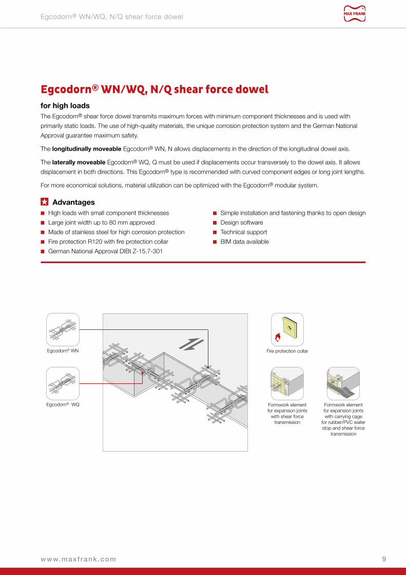
Egcodorn® WN Fire protection collar
Formwork element for expansion joints
with shear force transmission
Formwork element for expansion joints with carrying cage
for rubber/PVC water stop and shear force
transmission
Egcodorn® WQ
Egcodorn® WN/WQ, N/Q shear force dowelfor high loadsThe Egcodorn® shear force dowel transmits maximum forces with minimum component thicknesses and is used with
primarily static loads. The use of high-quality materials, the unique corrosion protection system and the German National
Approval guarantee maximum safety.
The longitudinally moveable Egcodorn® WN, N allows displacements in the direction of the longitudinal dowel axis.
The laterally moveable Egcodorn® WQ, Q must be used if displacements occur transversely to the dowel axis. It allows
displacement in both directions. This Egcodorn® type is recommended with curved component edges or long joint lengths.
For more economical solutions, material utilization can be optimized with the Egcodorn® modular system.
Advantages ■ High loads with small component thicknesses
■ Large joint width up to 80 mm approved
■ Made of stainless steel for high corrosion protection
■ Fire protection R120 with fire protection collar
■ German National Approval DIBt Z-15.7-301
■ Simple installation and fastening thanks to open design
■ Design software
■ Technical support
■ BIM data available
Egcodorn® WN/WQ, N/Q shear force dowel
9www.maxf rank .com

Technical Information
Technical Information
Load-bearing behaviourThe shear forces occurring in the joint are absorbed by the dowel and
reliably transmitted into and anchored with the associated anchor body. The
full anchorage of the occurring forces is secured with concrete qualities of
C20/25 or higher.
Depending on the type selected, displacements are allowed exclusively
in the longitudinal dowel direction (Egcodorn® WN, N) or in the horizontal
transverse direction to the dowel (Egcodorn® WQ, Q).
The dowel and anchor body of the Egcodorn® are matched to typical
construction boundary conditions. Depending on the desired load-bearing
capacity and geometric boundary conditions, a suitable Egcodorn® can be
selected from the standard range. Moreover, it is possible to optimise the
dowel connection for the individual application with the Egcodorn® modular
system.
Corrosion protectionWith the core-jacket system, the Egcodorn® combines the outstanding mechanical properties of the high-strength load-
bearing dowel core with the excellent corrosion protection of the stainless steel jacket (corrosion resistance class III). During
the mechanical processing the surface is tempered, which leads to particularly favourable sliding properties.
Steel core
Silicone rubber
Stainless steel jacket
Egcodorn® WN for longitudinal
movement
Egcodorn® WQ for longitudinal and
transverse movement
www.maxf rank .com10

Accessories
Fire protection collarIf there are fire protection requirements to be met, the Egcodorn® shear force
dowels can be protected with the optionally available fire protection collar;
the classification is then R120. The suitable fire protection collar is selected
in relation to the dowel type and joint width, as standard 20 to 60 mm. The
air gap between fire protection collar and concrete surface must be no wider
than 10 mm.
Installation
31 2
Accessories
11www.maxf rank .com

Standard types
Standard types
Standard typeWN / WQ N / Q
40 50 70 95 100 120 150 210 300 350 400
External diameter of dowel D1) [mm] 22 24 27 30 32 34 37 42 44 52 52Height of anchor body hD [mm] 80 100 120 140 140 170 170 200 240 240 240Length of anchor body lb [mm] 156 187 218 250 250 312 312 390 390 390 1030Width of anchor body bb [mm] 173 187 222 222 222 261 261 308 330 330 268
Standard typeWN / WQ N / Q
40 50 70 95 100 120 150 210 300 350 400
Pos. 1:U-stirrups in dowel direction, 2 per side Ø10 Ø10 Ø10 Ø12 Ø12 Ø14 Ø14 Ø16 Ø20 Ø20 Ø20
Maximum spacing sx [mm] 30 30 30 50 50 70 70 90 100 100 100Pos. 2: Edge reinforcement transverse to dowel [n Ø dsy], top and bottom 1Ø10 1Ø10 1Ø10 1Ø12 1Ø12 1Ø14 1Ø14 1Ø16 1Ø20 1Ø20 1Ø20
Standard typeWN / WQ N / Q
40 50 70 95 100 120 150 210 300 350 400
Minimum slab thickness hmin [mm] 140 160 180 200 210 230 250 280 300 350 350Minimum component depth tw
2) [mm] 176 207 238 270 270 332 332 410 410 410 1050Minimum component width bw [mm] 220 240 280 300 320 340 380 420 460 520 520Minimum edge distance ar [mm] 70 80 90 100 105 115 125 140 150 175 175Minimum edge distance ar1 [mm] 110 120 140 150 160 170 190 210 230 260 260Calc. value for column width lc [mm] 100 100 115 130 130 165 165 210 210 210 210Height hk
3) [mm] 220 240 260 290 300 320 340 380 400 410 440Cap stirrup diameter [mm] 6 6 6 6 6 8 8 10 10 12 12
Dimensions
Minimum reinforcement for local load introduction (anchoring outside the punching shear cone)
Application
1) Core diameter = external diameter – 2 mm2) Assumption: cnom = 20 mm3) A cap stirrup is to be used if the slab thickness h is < hkStandard joint width z ≤ 60 mm; joint width z ≤ 80 mm on enquiryCustom Egcodorn® versions on enquiry, see also Egcodorn® modular system p. 13
l blcbb
ds
h D
D
h
Cap stirrup if h < hk
≥ t w
h ≥
h min
≥ a r
≥ ar1≥ bw
≤ dsx
≤ max sx
d eff
Pos. 1
Pos. 2
z max
z max
≤ 60 mm: Standard
≤ 80 mm: Special
500 mm
500 mm
* Egcodorn® type WQ/Q transverse displacement ±15 mm
www.maxf rank .com12
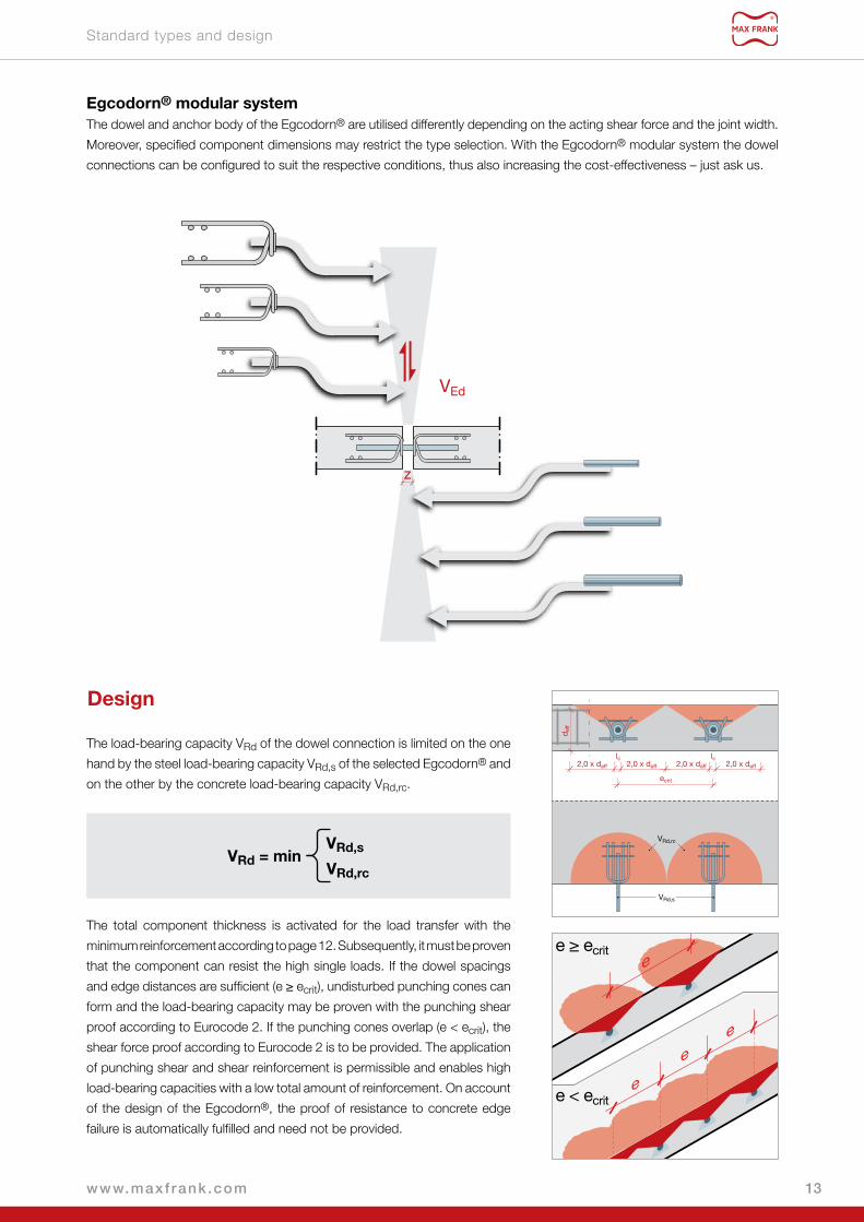
Standard types and design
Egcodorn® modular systemThe dowel and anchor body of the Egcodorn® are utilised differently depending on the acting shear force and the joint width.
Moreover, specified component dimensions may restrict the type selection. With the Egcodorn® modular system the dowel
connections can be configured to suit the respective conditions, thus also increasing the cost-effectiveness – just ask us.
z
VEd
The load-bearing capacity VRd of the dowel connection is limited on the one
hand by the steel load-bearing capacity VRd,s of the selected Egcodorn® and
on the other by the concrete load-bearing capacity VRd,rc.
VRd,s
VRd,rcVRd = min
The total component thickness is activated for the load transfer with the
minimum reinforcement according to page 12. Subsequently, it must be proven
that the component can resist the high single loads. If the dowel spacings
and edge distances are sufficient (e ≥ ecrit), undisturbed punching cones can
form and the load-bearing capacity may be proven with the punching shear
proof according to Eurocode 2. If the punching cones overlap (e < ecrit), the
shear force proof according to Eurocode 2 is to be provided. The application
of punching shear and shear reinforcement is permissible and enables high
load-bearing capacities with a low total amount of reinforcement. On account
of the design of the Egcodorn®, the proof of resistance to concrete edge
failure is automatically fulfilled and need not be provided.
e
e
e
e
e ≥ ecrit
e < ecrit
2,0 x deff 2,0 x deff 2,0 x deff 2,0 x deff
lc lc
ecrit
d eff
VRd,rc
VRd,s
Design
13www.maxf rank .com

General procedure – design of slabsThe suitable Egcodorn® shear force dowels and the corresponding dowel spacings are selected according to the
component properties, action and joint width. The load-bearing capacity of the slab in the load application area is then
checked with these boundary conditions, with the application of the punching shear or shear force resistance proof
depending on the dowel spacing, wherein provision may be made for punching shear or shear reinforcement.
Proof of steel load-bearing capacity VRd,s according to joint width z
Punching shear proof with no overlapping of the punching cones
Shear force proof with overlapping of the punching cones
Checking the dowel spacings
Proof of concrete load-bearing capacity VRd,rc
Checking hmin
D
without punching shear reinforcement
Increased degree of longitudinal reinforcement
with punching shear reinforcement
High load-bearing capacity with optimum utilisation of reinforcement
D
without shear reinforcement
Increased degree of longitudinal reinforcement
D
with shear reinforcement
High load-bearing capacity with optimum utilisation of
reinforcement
h
A
h ≥ hmin
VEd
z B
e
C
e ≥ ecrit
e
e
e
C
e < ecrit
Design
D
www.maxf rank .com14

Design
B
C
D Proof of concrete load-bearing capacity VRd,rcIn the case of undisturbed load distribution (fig. C-1), the slab load-
bearing capacity can be determined in the direct load application area
with application of the punching shear resistance (section 6.4 EC2).
Otherwise, the shear resistance is decisive for the slab (section 6.2
EC2). The punching shear or shear reinforcement may also be
applied. The strength classes C20/25 to C50/60 may be used for the
proof of the concrete load-bearing capacity.
Checking hminThe suitable Egcodorn® is selected according to the existing component
geometry. Particular attention must be paid to hmin with slabs.
Proof of steel load-bearing capacity VRd,s according to joint width zOn the basis of the specified joint width z and the design loads VEd,
the dowel spacings can now be defined and the proof of the steel
load-bearing capacity VRd,s can be provided for the Egcodorn®. The
respectively maximum occurring joint opening is to be taken as the joint
width z.
Checking the dowel spacingsOn the basis of the selected dowel spacings, you can now check
whether the punching cones can form undisturbed. The result of this
check is decisive for the proof format for the concrete load-bearing
capacity.
tw ≥ tw m
inh ≥ hmin
e
e
e
1
2
VEd
z
A h ≥ hmin
15www.maxf rank .com

Design
Egcodorn® steel load-bearing capacityProvided concrete failure of the connected components can be ruled out, the system load-bearing capacity of the dowel
connection is given by the steel load-bearing capacity of the respective Egcodorn®. A distinction must be made as to whether
the displacement occurs in one direction (longitudinal or transverse) or in two directions (longitudinal and transverse). The
values in the following tables are the minimum values for the steel load-bearing capacities of dowel and anchor body for various
joint widths and were determined on the basis of the German National Approval Z-15.7-301.
Joint width [mm]WN / WQ N / Q
40 50 70 95 100 120 150 210 300 350 400
10 62.0 89.4 122.3 154.7 155.8 241.5 243.8 380.3 382.1 388.0 486.720 58.9 85.3 117.4 149.1 150.6 224.4 236.8 369.5 373.0 380.2 476.930 54.5 72.2 102.9 138.7 145.7 194.1 230.3 331.6 364.4 372.7 467.640 40.9 54.5 79.9 112.2 136.9 163.8 208.4 293.8 331.9 365.6 458.650 32.7 43.6 63.9 89.8 110.5 134.1 175.3 255.9 292.1 358.7 449.960 27.3 36.3 53.3 74.8 92.0 111.7 146.2 218.2 252.4 352.0 411.770 23.4 31.1 45.7 64.1 78.9 95.8 125.3 187.0 216.5 345.6 364.480 20.5 27.2 40.0 56.1 69.0 83.8 109.6 163.6 189.4 319.6 319.6
VRd,s [kN] longitudinal displacement
Joint width [mm]WQ Q
40 50 70 95 100 120 150 210 300 350 400
10 62.0 89.4 122.3 154.7 155.8 229.2 243.8 366.6 382.1 388.0 486.720 58.9 83.7 113.9 148.6 150.6 201.9 236.8 332.6 370.2 380.2 476.930 49.1 65.0 92.6 124.8 145.7 174.7 217.3 298.5 334.4 372.7 467.640 36.8 49.0 71.9 100.9 123.2 147.4 187.5 264.4 298.7 365.6 455.750 29.5 39.2 57.5 80.8 99.4 120.6 157.7 230.3 262.9 358.7 413.260 24.5 32.7 47.9 67.4 82.8 100.5 131.5 196.4 227.1 352.0 370.670 21.0 28.0 41.1 57.7 71.0 86.2 112.8 168.3 194.8 328.0 328.080 18.4 24.5 36.0 50.5 62.1 75.4 98.7 147.3 170.5 287.6 287.6
VRd,s [kN] longitudinal and transverse displacement
Standard joint width z ≤ 60 mm, joint width z ≤ 80 mm on enquiry
www.maxf rank .com16

Design
In particular in the case of thin reinforced concrete slabs, the attainment of the steel load-bearing capacity of the Egcodorn
cannot readily be presupposed – the slab load-bearing capacity in the load application area is often decisive here. Two execution
variants for the simplification of the preliminary design of Egcodorn dowels in reinforced concrete slabs are presented below:
full load-bearing capacity in case of variant 1 with shear reinforcement as well as adapted load-bearing capacity in case
of variant 2 without shear / punching shear reinforcement.
Variant 1: full steel load-bearing capacity – small dowel spacing – with shear reinforcementShear reinforcement is to be provided if the steel load-bearing capacity of the Egcodorn is to be fully utilised with small dowel
spacings in the reinforced concrete slabs.
For simplification of the preliminary design, the following table based on DIN EN 1992-1-1 shows the assumptions under which
the steel load-bearing capacity of the Egcodorn® shear force dowels can be fully activated in reinforced steel slabs according
to page 16. The specified shear reinforcement (diameter and bar spacings) was selected on the basis of the respectively
least favourable boundary conditions (action, slab thickness, dowel spacing, concrete). When taking into account the actual
conditions, much lower degrees of shear reinforcement result in many cases.
Tip: Use our design software!
Standard typeWN / WQ N / Q
40 50 70 95 100 120 150 210 300 350 400
Minimum slab thickness hsup [mm] 200 200 200 200 210 230 250 280 300 350 350Minimum dowel spacing esup2) [mm] 260 380 520 660 600 790 690 880 830 660 830Cap stirrup diameter3) [mm] 6 6 6 6 6 8 8 10 10 10 10Height hk [mm] 220 240 260 290 300 320 340 380 400 410 440Pos. 1: U-stirrup in dowel direction4) 4Ø10 4Ø10 4Ø10 4Ø12 4Ø12 4Ø16 4Ø16 4Ø16 4Ø20 4Ø20 4Ø20Pos. 2: Edge reinforcement transverse to dowel (top and bottom) 1Ø10 1Ø10 1Ø10 1Ø12 1Ø12 1Ø16 1Ø16 1Ø16 1Ø20 1Ø20 1Ø20
Shear reinforcement Pos. 3
Stirrup diameter [mm] 10 10 10 10 10 12 12 12 16 16 16Longitudinal spacing sl5) [cm] 0.5 hTransverse spacing st [cm] 15 15 15 15 15 15 15 15 25 20 20
Guiding value for reinforced concrete slabs – full steel load-bearing capacity, small dowel spacings, with shear reinforcement1)
Assumptions: C20/25 to C50/60, B500, cnom = 30 mm, h ≥ hsup, e ≥ esup, e ≤ 5h
1) The data in the table represent guiding values and must be proven in the individual case.2) Smaller dowel spacings are possible if the shear reinforcement is adapted. Recommendation: Use the Egcodorn design software.3) Cap stirrup only required with slab thickness h < hk.4) See p. 12 for arrangement.5) The max. xsw (see below) up to which the shear force stirrups are to be provided depends on the static system of the slab and is to be calculated for the respective boundary conditions or can be taken from the shear force proof for the slab. The maximum compression strut width in the shear force proof corresponds to the respectively selected dowel spacing.
≥ esup
St
St
sLsL
sLsL
sL
≥ esub
≥ h
sub
Pos. 1Pos. 2
Pos. 3
01
xsw
VEd
VEd,x = VRd,c
System load-bearing capacity for slabs according to Eurocode 2
17www.maxf rank .com

Design
Variant 2: adapted load-bearing capacity with bigger dowel spacings – increased degree of longitudinal reinforcement – without shear/punching shear reinforcementIf shear/punching shear reinforcement is to be dispensed with, then larger dowel spacings and an increased degree of
longitudinal reinforcement, in some cases with reduced load-bearing capacities, are mostly a requirement in reinforced
concrete slabs. The values for VRd given in the following tables represent the minimum of steel load-bearing capacity VRd,s
and concrete load-bearing capacity VRd,rc. The steel load-bearing capacity is authoritative in the case of the values in bold
lettering. The concrete load-bearing capacity was determined by way of example on the basis of DIN EN 1992-1-1 for some
standard cases; the calculation assumptions are given in the tables. In many cases, higher load-bearing capacities can be
achieved by modifying the reinforcement.
Download our free design software:
www .maxfrank .com/egcodorn-software
Or contact our Customer Service!
Phone +49 9427 189-320 | customer .service@maxfrank .de
Get support for your individual design tasks from our free and intuitively usable software or our technical
consultants!
Slab thickness h [mm]WN / WQ N / Q
40 50 70 95 100 120 150 210 300 350 400
160 580 572180 660 652 659200 740 732 739 762220 820 812 819 842 826250 940 932 939 962 946 981 981280 1060 1052 1059 1082 1066 1101 1101 1130300 1140 1132 1139 1162 1146 1181 1181 1210 1210350 1340 1332 1339 1362 1346 1381 1381 1410 1410 1410 1410400 1540 1532 1539 1562 1546 1581 1581 1610 1610 1610 1610600 2340 2332 2339 2362 2346 2381 2381 2410 2410 2410 2410
Dowel spacings/edge distancesThe following tables are based on the assumption that the forces can
propagate without mutual influencing of adjacent dowels; the following critical
spacings apply.
It is possible to use smaller spacings than these; however, the shear force
proof must then be provided instead of the punching shear proof on account
of the overlapping punching cones, and different load-bearing capacities may
result.
Critical dowel spacings ecrit
The minimum lateral edge distance is ecrit/2.
≥ ecrit≥ ecrit /2
≥ h m
in /2
≥ h m
in /2
www.maxf rank .com18

Design
In-situ reinforcementThe following reinforcement (or equivalent) is to be arranged and anchored outside of the punching shear cone when utilising
the loading-bearing capacities subsequently named.
In-situ reinforcement
Standard typeWN / WQ N / Q
40 50 70 95 100 120 150 210 300 350 400
Diameter of cap stirrup1) 6 6 6 6 6 8 8 10 10 10 10Height hk [mm] 220 240 260 290 300 320 340 380 400 410 440
Pos. 1: U-stirrup in dowel direction [n Ø dsx]
6Ø10 6Ø12 6Ø14 8Ø12 10Ø16 10Ø16 10Ø16 10Ø20 10Ø20 10Ø20 10Ø20
Maximum spacing sx [mm] 30 30 30 50 50 70 70 90 100 100 100Pos. 2: Edge reinforcement transverse to dowel [n Ø dsy], top and bottom 3Ø12 3Ø12 3Ø14 3Ø12 3Ø16 4Ø16 4Ø16 4Ø20 4Ø20 4Ø20 4Ø20
Reinforcement B5001) Only required with slab thickness h < hk, see page 12
lclbd lbd
h
d eff
≤ dsx
≤ maxsx lbd 302,0 * deff 2,0 * deff 2,0 * deff
Pos 1
Pos 2Pos2
Pos1
19www.maxf rank .com

Design
Slab thickness [mm] Joint width [mm]WN / WQ N / Q
40 50 70 95 100 120 150 210 300 350 400
160
20 48.2 50.230 48.2 50.240 40 .9 50.250 32 .7 43 .660 27 .3 36 .3
180
20 58.1 60.7 66.830 54 .5 60.7 66.840 40 .9 54 .5 66.850 32 .7 43 .6 63 .960 27 .3 36 .3 53 .3
200
20 58 .9 71.6 78.9 76.630 54 .5 71.6 78.9 76.640 40 .9 54 .5 78.9 76.650 32 .7 43 .6 63 .9 76.660 27 .3 36 .3 53 .3 74 .8
220
20 58 .9 83.0 91.5 88.6 108.330 54 .5 72 .2 91.5 88.6 108.340 40 .9 54 .5 79 .9 88.6 108.350 32 .7 43 .6 63 .9 88.6 108.360 27 .3 36 .3 53 .3 74 .8 92 .0
250
20 58 .9 85 .3 110.4 106.3 131.1 140.0 140.030 54 .5 72 .2 102 .9 106.3 131.1 140.0 140.040 40 .9 54 .5 79 .9 106.3 131.1 140.0 140.050 32 .7 43 .6 63 .9 89 .8 110 .5 134 .1 140.060 27 .3 36 .3 53 .3 74 .8 92 .0 111 .7 140.0
280
20 58 .9 85 .3 117 .4 121.7 150.4 160.2 160.2 186.430 54 .5 72 .2 102 .9 121.7 145 .7 160.2 160.2 186.440 40 .9 54 .5 79 .9 112 .2 136 .9 160.2 160.2 186.450 32 .7 43 .6 63 .9 89 .8 110 .5 134 .1 160.2 186.460 27 .3 36 .3 53 .3 74 .8 92 .0 111 .7 146 .2 186.4
300
20 58 .9 85 .3 117 .4 132.1 150 .6 173.9 173.9 202.3 202.330 54 .5 72 .2 102 .9 132.1 145 .7 173.9 173.9 202.3 202.340 40 .9 54 .5 79 .9 112 .2 136 .9 163 .8 173.9 202.3 202.350 32 .7 43 .6 63 .9 89 .8 110 .5 134 .1 173.9 202.3 202.360 27 .3 36 .3 53 .3 74 .8 92 .0 111 .7 146 .2 202.3 202.3
350
20 58 .9 85 .3 117 .4 149 .1 150 .6 208.9 208.9 242.9 242.9 242.9 242.930 54 .5 72 .2 102 .9 138 .7 145 .7 194 .1 208.9 242.9 242.9 242.9 242.940 40 .9 54 .5 79 .9 112 .2 136 .9 163 .8 208 .4 242.9 242.9 242.9 242.950 32 .7 43 .6 63 .9 89 .8 110 .5 134 .1 175 .3 242.9 242.9 242.9 242.960 27 .3 36 .3 53 .3 74 .8 92 .0 111 .7 146 .2 218 .2 242.9 242.9 242.9
400
20 58 .9 85 .3 117 .4 149 .1 150 .6 224 .4 236 .8 284.6 284.6 284.6 284.630 54 .5 72 .2 102 .9 138 .7 145 .7 194 .1 230 .3 284.6 284.6 284.6 284.640 40 .9 54 .5 79 .9 112 .2 136 .9 163 .8 208 .4 284.6 284.6 284.6 284.650 32 .7 43 .6 63 .9 89 .8 110 .5 134 .1 175 .3 255 .9 284.6 284.6 284.660 27 .3 36 .3 53 .3 74 .8 92 .0 111 .7 146 .2 218 .2 252 .4 284.6 284.6
600
20 58 .9 85 .3 117 .4 149 .1 150 .6 224 .4 236 .8 369 .5 373 .0 380 .2 460.630 54 .5 72 .2 102 .9 138 .7 145 .7 194 .1 230 .3 331 .6 364 .4 372 .7 460.640 40 .9 54 .5 79 .9 112 .2 136 .9 163 .8 208 .4 293 .8 331 .9 365 .6 458 .650 32 .7 43 .6 63 .9 89 .8 110 .5 134 .1 175 .3 255 .9 292 .1 358 .7 449 .960 27 .3 36 .3 53 .3 74 .8 92 .0 111 .7 146 .2 218 .2 252 .4 352 .0 411 .7
System load-bearing capacity of the dowel connection
VRd [kN] per dowel, C20/25, longitudinal displacement
Assumptions: adequate dowel spacings, see page 18
Reinforcement, see page 19
cnom = 30 mm
www.maxf rank .com20

Design
Slab thickness [mm] Joint width [mm]WN / WQ N / Q
40 50 70 95 100 120 150 210 300 350 400
160
20 51.9 54.130 51.9 54.140 40 .9 54.150 32 .7 43 .660 27 .3 36 .3
180
20 58 .9 65.4 71.930 54 .5 65.4 71.940 40 .9 54 .5 71.950 32 .7 43 .6 63 .960 27 .3 36 .3 53 .3
200
20 58 .9 77.1 85.0 82.530 54 .5 72 .2 85.0 82.540 40 .9 54 .5 79 .9 82.550 32 .7 43 .6 63 .9 82.560 27 .3 36 .3 53 .3 74 .8
220
20 58 .9 85 .3 98.6 95.4 116.730 54 .5 72 .2 98.6 95.4 116.740 40 .9 54 .5 79 .9 95.4 116.750 32 .7 43 .6 63 .9 89 .8 110 .560 27 .3 36 .3 53 .3 74 .8 92 .0
250
20 58 .9 85 .3 117 .4 114.5 141.2 150.8 150.830 54 .5 72 .2 102 .9 114.5 141.2 150.8 150.840 40 .9 54 .5 79 .9 112 .2 136 .9 150.8 150.850 32 .7 43 .6 63 .9 89 .8 110 .5 134 .1 150.860 27 .3 36 .3 53 .3 74 .8 92 .0 111 .7 146 .2
280
20 58 .9 85 .3 117 .4 131.1 150 .6 172.6 172.6 200.830 54 .5 72 .2 102 .9 131.1 145 .7 172.6 172.6 200.840 40 .9 54 .5 79 .9 112 .2 136 .9 163 .8 172.6 200.850 32 .7 43 .6 63 .9 89 .8 110 .5 134 .1 172.6 200.860 27 .3 36 .3 53 .3 74 .8 92 .0 111 .7 146 .2 200.8
300
20 58 .9 85 .3 117 .4 142.3 150 .6 187.4 187.4 218.0 218.030 54 .5 72 .2 102 .9 138 .7 145 .7 187.4 187.4 218.0 218.040 40 .9 54 .5 79 .9 112 .2 136 .9 163 .8 187.4 218.0 218.050 32 .7 43 .6 63 .9 89 .8 110 .5 134 .1 175 .3 218.0 218.060 27 .3 36 .3 53 .3 74 .8 92 .0 111 .7 146 .2 218.0 218.0
350
20 58 .9 85 .3 117 .4 149 .1 150 .6 224 .4 225.0 261.7 261.7 261.7 261.730 54 .5 72 .2 102 .9 138 .7 145 .7 194 .1 225.0 261.7 261.7 261.7 261.740 40 .9 54 .5 79 .9 112 .2 136 .9 163 .8 208 .4 261.7 261.7 261.7 261.750 32 .7 43 .6 63 .9 89 .8 110 .5 134 .1 175 .3 255 .9 261.7 261.7 261.760 27 .3 36 .3 53 .3 74 .8 92 .0 111 .7 146 .2 218 .2 252 .4 261.7 261.7
400
20 58 .9 85 .3 117 .4 149 .1 150 .6 224 .4 236 .8 306.5 306.5 306.5 306.530 54 .5 72 .2 102 .9 138 .7 145 .7 194 .1 230 .3 306.5 306.5 306.5 306.540 40 .9 54 .5 79 .9 112 .2 136 .9 163 .8 208 .4 293 .8 306.5 306.5 306.550 32 .7 43 .6 63 .9 89 .8 110 .5 134 .1 175 .3 255 .9 292 .1 306.5 306.560 27 .3 36 .3 53 .3 74 .8 92 .0 111 .7 146 .2 218 .2 252 .4 306.5 306.5
600
20 58 .9 85 .3 117 .4 149 .1 150 .6 224 .4 236 .8 369 .5 373 .0 380 .2 476 .930 54 .5 72 .2 102 .9 138 .7 145 .7 194 .1 230 .3 331 .6 364 .4 372 .7 467 .640 40 .9 54 .5 79 .9 112 .2 136 .9 163 .8 208 .4 293 .8 331 .9 365 .6 458 .650 32 .7 43 .6 63 .9 89 .8 110 .5 134 .1 175 .3 255 .9 292 .1 358 .7 449 .960 27 .3 36 .3 53 .3 74 .8 92 .0 111 .7 146 .2 218 .2 252 .4 352 .0 411 .7
System load-bearing capacity of the dowel connection
VRd [kN] per dowel, C25/30, longitudinal displacement
Assumptions: adequate dowel spacings, see page 18
Reinforcement, see page 19
cnom = 30 mm
21www.maxf rank .com

Design
Slab thickness [mm] Joint width [mm]WN / WQ N / Q
40 50 70 95 100 120 150 210 300 350 400
160
20 55.2 57.430 54 .5 57.440 40 .9 54 .550 32 .7 43 .660 27 .3 36 .3
180
20 58 .9 69.5 76.430 54 .5 69.5 76.440 40 .9 54 .5 76.450 32 .7 43 .6 63 .960 27 .3 36 .3 53 .3
200
20 58 .9 82.0 90.3 87.730 54 .5 72 .2 90.3 87.740 40 .9 54 .5 79 .9 87.750 32 .7 43 .6 63 .9 87.760 27 .3 36 .3 53 .3 74 .8
220
20 58 .9 85 .3 104.7 101.4 124.030 54 .5 72 .2 102 .9 101.4 124.040 40 .9 54 .5 79 .9 101.4 124.050 32 .7 43 .6 63 .9 89 .8 110 .560 27 .3 36 .3 53 .3 74 .8 92 .0
250
20 58 .9 85 .3 117 .4 121.7 150.1 160.2 160.230 54 .5 72 .2 102 .9 121.7 145 .7 160.2 160.240 40 .9 54 .5 79 .9 112 .2 136 .9 160.2 160.250 32 .7 43 .6 63 .9 89 .8 110 .5 134 .1 160.260 27 .3 36 .3 53 .3 74 .8 92 .0 111 .7 146 .2
280
20 58 .9 85 .3 117 .4 139.3 150 .6 183.4 183.4 213.430 54 .5 72 .2 102 .9 138 .7 145 .7 183.4 183.4 213.440 40 .9 54 .5 79 .9 112 .2 136 .9 163 .8 183.4 213.450 32 .7 43 .6 63 .9 89 .8 110 .5 134 .1 175 .3 213.460 27 .3 36 .3 53 .3 74 .8 92 .0 111 .7 146 .2 213.4
300
20 58 .9 85 .3 117 .4 149 .1 150 .6 199.1 199.1 231.6 231.630 54 .5 72 .2 102 .9 138 .7 145 .7 194 .1 199.1 231.6 231.640 40 .9 54 .5 79 .9 112 .2 136 .9 163 .8 199.1 231.6 231.650 32 .7 43 .6 63 .9 89 .8 110 .5 134 .1 175 .3 231.6 231.660 27 .3 36 .3 53 .3 74 .8 92 .0 111 .7 146 .2 218 .2 231.6
350
20 58 .9 85 .3 117 .4 149 .1 150 .6 224 .4 236 .8 278.1 278.1 278.1 278.130 54 .5 72 .2 102 .9 138 .7 145 .7 194 .1 230 .3 278.1 278.1 278.1 278.140 40 .9 54 .5 79 .9 112 .2 136 .9 163 .8 208 .4 278.1 278.1 278.1 278.150 32 .7 43 .6 63 .9 89 .8 110 .5 134 .1 175 .3 255 .9 278.1 278.1 278.160 27 .3 36 .3 53 .3 74 .8 92 .0 111 .7 146 .2 218 .2 252 .4 278.1 278.1
400
20 58 .9 85 .3 117 .4 149 .1 150 .6 224 .4 236 .8 325.8 325.8 325.8 325.830 54 .5 72 .2 102 .9 138 .7 145 .7 194 .1 230 .3 325.8 325.8 325.8 325.840 40 .9 54 .5 79 .9 112 .2 136 .9 163 .8 208 .4 293 .8 325.8 325.8 325.850 32 .7 43 .6 63 .9 89 .8 110 .5 134 .1 175 .3 255 .9 292 .1 325.8 325.860 27 .3 36 .3 53 .3 74 .8 92 .0 111 .7 146 .2 218 .2 252 .4 325.8 325.8
600
20 58 .9 85 .3 117 .4 149 .1 150 .6 224 .4 236 .8 369 .5 373 .0 380 .2 476 .930 54 .5 72 .2 102 .9 138 .7 145 .7 194 .1 230 .3 331 .6 364 .4 372 .7 467 .640 40 .9 54 .5 79 .9 112 .2 136 .9 163 .8 208 .4 293 .8 331 .9 365 .6 458 .650 32 .7 43 .6 63 .9 89 .8 110 .5 134 .1 175 .3 255 .9 292 .1 358 .7 449 .960 27 .3 36 .3 53 .3 74 .8 92 .0 111 .7 146 .2 218 .2 252 .4 352 .0 411 .7
System load-bearing capacity of the dowel connection
VRd [kN] per dowel, C30/37, longitudinal displacement
Assumptions: adequate dowel spacings, see page 18
Reinforcement, see page 19
cnom = 30 mm
www.maxf rank .com22

Design
Slab thickness [mm] Joint width [mm]WQ Q
40 50 70 95 100 120 150 210 300 350 400
160
20 48.2 50.230 48.2 50.240 36 .8 49 .050 29 .5 39 .260 24 .5 32 .7
180
20 58.1 60.7 66.830 49 .1 60.7 66.840 36 .8 49 .0 66.850 29 .5 39 .2 57 .560 24 .5 32 .7 47 .9
200
20 58 .9 71.6 78.9 76.630 49 .1 65 .0 78.9 76.640 36 .8 49 .0 71 .9 76.650 29 .5 39 .2 57 .5 76.660 24 .5 32 .7 47 .9 67 .4
220
20 58 .9 83.0 91.5 88.6 108.330 49 .1 65 .0 91.5 88.6 108.340 36 .8 49 .0 71 .9 88.6 108.350 29 .5 39 .2 57 .5 80 .8 99 .460 24 .5 32 .7 47 .9 67 .4 82 .8
250
20 58 .9 83 .7 110.4 106.3 131.1 140.0 140.030 49 .1 65 .0 92 .6 106.3 131.1 140.0 140.040 36 .8 49 .0 71 .9 100 .9 123 .2 140.0 140.050 29 .5 39 .2 57 .5 80 .8 99 .4 120 .6 140.060 24 .5 32 .7 47 .9 67 .4 82 .8 100 .5 131 .5
280
20 58 .9 83 .7 113 .9 121.7 150.4 160.2 160.2 186.430 49 .1 65 .0 92 .6 121.7 145 .7 160.2 160.2 186.440 36 .8 49 .0 71 .9 100 .9 123 .2 147 .4 160.2 186.450 29 .5 39 .2 57 .5 80 .8 99 .4 120 .6 157 .7 186.460 24 .5 32 .7 47 .9 67 .4 82 .8 100 .5 131 .5 186.4
300
20 58 .9 83 .7 113 .9 132.1 150 .6 173.9 173.9 202.3 202.330 49 .1 65 .0 92 .6 124 .8 145 .7 173.9 173.9 202.3 202.340 36 .8 49 .0 71 .9 100 .9 123 .2 147 .4 173.9 202.3 202.350 29 .5 39 .2 57 .5 80 .8 99 .4 120 .6 157 .7 202.3 202.360 24 .5 32 .7 47 .9 67 .4 82 .8 100 .5 131 .5 196 .4 202.3
350
20 58 .9 83 .7 113 .9 148 .6 150 .6 201 .9 208.9 242.9 242.9 242.9 242.930 49 .1 65 .0 92 .6 124 .8 145 .7 174 .7 208.9 242.9 242.9 242.9 242.940 36 .8 49 .0 71 .9 100 .9 123 .2 147 .4 187 .5 242.9 242.9 242.9 242.950 29 .5 39 .2 57 .5 80 .8 99 .4 120 .6 157 .7 230 .3 242.9 242.9 242.960 24 .5 32 .7 47 .9 67 .4 82 .8 100 .5 131 .5 196 .4 227 .1 242.9 242.9
400
20 58 .9 83 .7 113 .9 148 .6 150 .6 201 .9 236 .8 284.6 284.6 284.6 284.630 49 .1 65 .0 92 .6 124 .8 145 .7 174 .7 217 .3 284.6 284.6 284.6 284.640 36 .8 49 .0 71 .9 100 .9 123 .2 147 .4 187 .5 264 .4 284.6 284.6 284.650 29 .5 39 .2 57 .5 80 .8 99 .4 120 .6 157 .7 230 .3 262 .9 284.6 284.660 24 .5 32 .7 47 .9 67 .4 82 .8 100 .5 131 .5 196 .4 227 .1 284.6 284.6
600
20 58 .9 83 .7 113 .9 148 .6 150 .6 201 .9 236 .8 332 .6 370 .2 380 .2 460.630 49 .1 65 .0 92 .6 124 .8 145 .7 174 .7 217 .3 298 .5 334 .4 372 .7 460.640 36 .8 49 .0 71 .9 100 .9 123 .2 147 .4 187 .5 264 .4 298 .7 365 .6 455 .750 29 .5 39 .2 57 .5 80 .8 99 .4 120 .6 157 .7 230 .3 262 .9 358 .7 413 .260 24 .5 32 .7 47 .9 67 .4 82 .8 100 .5 131 .5 196 .4 227 .1 352 .0 370 .6
System load-bearing capacity of the dowel connection
VRd [kN] per dowel, C20/25, longitudinal and transverse displacement
Assumptions: adequate dowel spacings, see page 18
Reinforcement, see page 19
cnom = 30 mm
23www.maxf rank .com
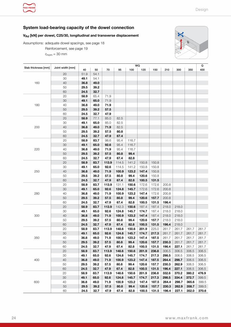
Design
Slab thickness [mm] Joint width [mm]WQ Q
40 50 70 95 100 120 150 210 300 350 400
160
20 51.9 54.130 49 .1 54.140 36 .8 49 .050 29 .5 39 .260 24 .5 32 .7
180
20 58 .9 65.4 71.930 49 .1 65 .0 71.940 36 .8 49 .0 71 .950 29 .5 39 .2 57 .560 24 .5 32 .7 47 .9
200
20 58 .9 77.1 85.0 82.530 49 .1 65 .0 85.0 82.540 36 .8 49 .0 71 .9 82.550 29 .5 39 .2 57 .5 80 .860 24 .5 32 .7 47 .9 67 .4
220
20 58 .9 83 .7 98.6 95.4 116.730 49 .1 65 .0 92 .6 95.4 116.740 36 .8 49 .0 71 .9 95.4 116.750 29 .5 39 .2 57 .5 80 .8 99 .460 24 .5 32 .7 47 .9 67 .4 82 .8
250
20 58 .9 83 .7 113 .9 114.5 141.2 150.8 150.830 49 .1 65 .0 92 .6 114.5 141.2 150.8 150.840 36 .8 49 .0 71 .9 100 .9 123 .2 147 .4 150.850 29 .5 39 .2 57 .5 80 .8 99 .4 120 .6 150.860 24 .5 32 .7 47 .9 67 .4 82 .8 100 .5 131 .5
280
20 58 .9 83 .7 113 .9 131.1 150 .6 172.6 172.6 200.830 49 .1 65 .0 92 .6 124 .8 145 .7 172.6 172.6 200.840 36 .8 49 .0 71 .9 100 .9 123 .2 147 .4 172.6 200.850 29 .5 39 .2 57 .5 80 .8 99 .4 120 .6 157 .7 200.860 24 .5 32 .7 47 .9 67 .4 82 .8 100 .5 131 .5 196 .4
300
20 58 .9 83 .7 113 .9 142.3 150 .6 187.4 187.4 218.0 218.030 49 .1 65 .0 92 .6 124 .8 145 .7 174 .7 187.4 218.0 218.040 36 .8 49 .0 71 .9 100 .9 123 .2 147 .4 187.4 218.0 218.050 29 .5 39 .2 57 .5 80 .8 99 .4 120 .6 157 .7 218.0 218.060 24 .5 32 .7 47 .9 67 .4 82 .8 100 .5 131 .5 196 .4 218.0
350
20 58 .9 83 .7 113 .9 148 .6 150 .6 201 .9 225.0 261.7 261.7 261.7 261.730 49 .1 65 .0 92 .6 124 .8 145 .7 174 .7 217 .3 261.7 261.7 261.7 261.740 36 .8 49 .0 71 .9 100 .9 123 .2 147 .4 187 .5 261.7 261.7 261.7 261.750 29 .5 39 .2 57 .5 80 .8 99 .4 120 .6 157 .7 230 .3 261.7 261.7 261.760 24 .5 32 .7 47 .9 67 .4 82 .8 100 .5 131 .5 196 .4 227 .1 261.7 261.7
400
20 58 .9 83 .7 113 .9 148 .6 150 .6 201 .9 236 .8 306.5 306.5 306.5 306.530 49 .1 65 .0 92 .6 124 .8 145 .7 174 .7 217 .3 298 .5 306.5 306.5 306.540 36 .8 49 .0 71 .9 100 .9 123 .2 147 .4 187 .5 264 .4 298 .7 306.5 306.550 29 .5 39 .2 57 .5 80 .8 99 .4 120 .6 157 .7 230 .3 262 .9 306.5 306.560 24 .5 32 .7 47 .9 67 .4 82 .8 100 .5 131 .5 196 .4 227 .1 306.5 306.5
600
20 58 .9 83 .7 113 .9 148 .6 150 .6 201 .9 236 .8 332 .6 370 .2 380 .2 476 .930 49 .1 65 .0 92 .6 124 .8 145 .7 174 .7 217 .3 298 .5 334 .4 372 .7 399.540 36 .8 49 .0 71 .9 100 .9 123 .2 147 .4 187 .5 264 .4 298 .7 365 .6 399.550 29 .5 39 .2 57 .5 80 .8 99 .4 120 .6 157 .7 230 .3 262 .9 358 .7 399.560 24 .5 32 .7 47 .9 67 .4 82 .8 100 .5 131 .5 196 .4 227 .1 352 .0 370 .6
System load-bearing capacity of the dowel connection
VRd [kN] per dowel, C25/30, longitudinal and transverse displacement
Assumptions: adequate dowel spacings, see page 18
Reinforcement, see page 19
cnom = 30 mm
www.maxf rank .com24

Design
Slab thickness [mm] Joint width [mm]WQ Q
40 50 70 95 100 120 150 210 300 350 400
160
20 55.2 57.430 49 .1 57.440 36 .8 49 .050 29 .5 39 .260 24 .5 32 .7
180
20 58 .9 69.5 76.430 49 .1 65 .0 76.440 36 .8 49 .0 71 .950 29 .5 39 .2 57 .560 24 .5 32 .7 47 .9
200
20 58 .9 82.0 90.3 87.730 49 .1 65 .0 90.3 87.740 36 .8 49 .0 71 .9 87.750 29 .5 39 .2 57 .5 80 .860 24 .5 32 .7 47 .9 67 .4
220
20 58 .9 83 .7 104.7 101.4 124.030 49 .1 65 .0 92 .6 101.4 124.040 36 .8 49 .0 71 .9 100 .9 123 .250 29 .5 39 .2 57 .5 80 .8 99 .460 24 .5 32 .7 47 .9 67 .4 82 .8
250
20 58 .9 83 .7 113 .9 121.7 150.1 160.2 160.230 49 .1 65 .0 92 .6 121.7 145 .7 160.2 160.240 36 .8 49 .0 71 .9 100 .9 123 .2 147 .4 160.250 29 .5 39 .2 57 .5 80 .8 99 .4 120 .6 157 .760 24 .5 32 .7 47 .9 67 .4 82 .8 100 .5 131 .5
280
20 58 .9 83 .7 113 .9 139.3 150 .6 183.4 183.4 213.430 49 .1 65 .0 92 .6 124 .8 145 .7 174 .7 183.4 213.440 36 .8 49 .0 71 .9 100 .9 123 .2 147 .4 183.4 213.450 29 .5 39 .2 57 .5 80 .8 99 .4 120 .6 157 .7 213.460 24 .5 32 .7 47 .9 67 .4 82 .8 100 .5 131 .5 196 .4
300
20 58 .9 83 .7 113 .9 148 .6 150 .6 199.1 199.1 231.6 231.630 49 .1 65 .0 92 .6 124 .8 145 .7 174 .7 199.1 231.6 231.640 36 .8 49 .0 71 .9 100 .9 123 .2 147 .4 187 .5 231.6 231.650 29 .5 39 .2 57 .5 80 .8 99 .4 120 .6 157 .7 230 .3 231.660 24 .5 32 .7 47 .9 67 .4 82 .8 100 .5 131 .5 196 .4 227 .1
350
20 58 .9 83 .7 113 .9 148 .6 150 .6 201 .9 236 .8 278.1 278.1 278.1 278.130 49 .1 65 .0 92 .6 124 .8 145 .7 174 .7 217 .3 278.1 278.1 278.1 278.140 36 .8 49 .0 71 .9 100 .9 123 .2 147 .4 187 .5 264 .4 278.1 278.1 278.150 29 .5 39 .2 57 .5 80 .8 99 .4 120 .6 157 .7 230 .3 262 .9 278.1 278.160 24 .5 32 .7 47 .9 67 .4 82 .8 100 .5 131 .5 196 .4 227 .1 278.1 278.1
400
20 58 .9 83 .7 113 .9 148 .6 150 .6 201 .9 236 .8 325.8 325.8 325.8 325.830 49 .1 65 .0 92 .6 124 .8 145 .7 174 .7 217 .3 298 .5 325.8 325.8 325.840 36 .8 49 .0 71 .9 100 .9 123 .2 147 .4 187 .5 264 .4 298 .7 325.8 325.850 29 .5 39 .2 57 .5 80 .8 99 .4 120 .6 157 .7 230 .3 262 .9 325.8 325.860 24 .5 32 .7 47 .9 67 .4 82 .8 100 .5 131 .5 196 .4 227 .1 325.8 325.8
600
20 58 .9 83 .7 113 .9 148 .6 150 .6 201 .9 236 .8 332 .6 370 .2 380 .2 476 .930 49 .1 65 .0 92 .6 124 .8 145 .7 174 .7 217 .3 298 .5 334 .4 372 .7 467 .640 36 .8 49 .0 71 .9 100 .9 123 .2 147 .4 187 .5 264 .4 298 .7 365 .6 455 .750 29 .5 39 .2 57 .5 80 .8 99 .4 120 .6 157 .7 230 .3 262 .9 358 .7 413 .260 24 .5 32 .7 47 .9 67 .4 82 .8 100 .5 131 .5 196 .4 227 .1 352 .0 370 .6
System load-bearing capacity of the dowel connection
VRd [kN] per dowel, C30/37, longitudinal and transverse displacement
Assumptions: adequate dowel spacings, see page 18
Reinforcement, see page 19
cnom = 30 mm
25www.maxf rank .com

Application guidelines
h
20 mm 80 mm
5 6
3 4
1 2
1 2!
These application guidelines can only be regarded as a recommendation. They are no substitute for the specialised knowledge required for the installation. The instructions are always kept at the latest state of the art and are continually updated. Technical amendments are therefore expressly reserved - including without prior information to the customer. The most recent version can be found on our website at: www .maxfrank .com. Our general terms of sale are also applicable.
www.maxf rank .com26

How to
1
31 2
How to
Expansion joints with seal and shear force transmissionThe construction of expansion joints in concrete elements is often very time-
consuming in the planning and execution, especially when waterstops and
components for the transmission of shear forces also have to be installed in
the joints.
Planning and execution errors are avoided and faster building progress
ensured through the use of prefabricated expansion joint rubber water bars,
in which the shear force dowels and a receptacle cage for rubber water bars
for expansion joints are already integrated.
How to:
■ The Stremaform® formwork elements for expansion joints are adapted precisely to the foundation planning. All
standard and custom elements – such as transitions from the floor slab to the rising wall – are designed and produced
in the works and delivered to the building site ready to install. Each element is allocated to its exact position in the
formwork plan beforehand so that the detailed planning doesn't collide with the execution on site.
■ The Egcodorn® shear force dowels, with which maximum shear forces can be transmitted even with minimum
component thicknesses, are already integrated ex works. This significantly shortens the assembly time on the building
site.
■ The expansion joint rubber water bar is inserted on site so that it can be installed with the least number of joints
possible.
27www.maxf rank .com

EgcodubelShear force dowel for small and medium loads

Egcodubel for longi-tudinal and transver-
se movement
Egcodubel for longi-tudinal movement
Egcodubel for lon-gitudinal movement
– plastic sleeve
Dowel without sleeve
Egcodubel beddingFire protection collar
Egcodubel dowel with stainless steel
casing
Egcodubel dowel, galvanised
Egcodubel dowel with full coating
Egcodubel dowel with single-sided
coating
Dowel with sleeve
Egcodubel shear force dowelfor small to medium loadsThe Egcodubel serves to transmit shear forces in joints. The use of dowels is usually limited to statically subordinate
applications (e.g. floor slabs).
Egcodubel dowels with sleeves are used for expansion joints and with small to medium loads or for structural component
connection. Egcodubel dowels are available without sleeves for dowelling working and dummy joints. The Egcodubel
dowels are chosen in a stainless steel or galvanised version depending on the area of use.
Advantages ■ Extensive product range
■ Inexpensive connection
■ Fire protection R120 with fire protection collar
■ Fully plastic-coated Egcodubel with CE marking
Egcodubel transverse force dowels
29www.maxf rank .com

Type overview
Egcodubel with plastic sleeveWith simple load-bearing or structural connections of components, the
Egcodubel can be used together with a longitudinally movable plastic sleeve.
The variants S355 and HF are available as core material. Depending on the
desired corrosion protection, Egcodubel dowels with stainless steel jacket or
in a hot-dip galvanised version are used.
Egcodubel for longitudinal movement,
plastic sleeve
Egcodubel with stainless steel sleeveEgcodubel dowels with stainless steel jacket in conjunction with stainless
steel sleeves offer excellent corrosion protection (corrosion resistance class
III) and can also be used in corrosive environments. Depending on the desired
load resistance, the dowel core can be selected in the standard quality
S355 or in high-strength HF material. Either a longitudinal or, a longitudinal
and transverse movable sleeve is chosen, depending on the direction of
movement.
Egcodubel for longitudinal
and transverse movement,
stainless steel sleeve
Egcodubel for longitudinal movement,
stainless steel sleeve
Type overview
Type designation
Example: Egcodubel EDM HF HQI
Egcodubel Type Dowel core Sleeve version1)
Sleeve version
Stainless steel sleeve for longitudinal movement
HI
Stainless steel sleeve for longitudinal and transverse
movementHQI
Plastic sleeve for longitudinal movement up to max. Ø 30 mm
H
Dowel type
Stainless steel casing
EDM
Galvanised2)
EDV
Example: Egcodubel EDM 27 HF HQI
Egcodubel Type Diameter Dowel core Sleeve version1)
Diameter [mm]
Dowel core/ dowel material
20
HF
22253)
274)
30374)
20
S35522
253)
274)
301) Optional, omitted if using the dowel without sleeve
2) Can only be combined with plastic sleeve.
3) Only in galvanised version4) Only in stainless steel version
www.maxf rank .com30

Type overview
Egcodubel stainless steel/
galvanised
Egcodubel without sleeveEgcodubel dowels are also available without sleeves for dowelling working or
dummy joints. If the corrosion protection is secured by the concrete cover, the
galvanised variant of the Egcodubel is adequate for working or dummy joints.
The variant with stainless steel jacket is used if higher corrosion protection
is desired. The variants S235, S355 and HF are available as core material.
Egcodubel galvanised and
coated
Egcodubel with coatingEgcodubel dowels with a soft plastic coating over half or the entire length are
suitable for dummy joints without the necessity for an additional sleeve. They
allow longitudinal displacements and prevent restraint stresses in the dowel
direction. The dowels are made from S235. The surface of the half-length
coated Egcodubel is hot-dip galvanised, it has an expansion sleeve.
Type designation
Coating6)
half-length coating, expansion sleeve
E
full plastic coating
B
Dowel type
Galvanised
EDV
Example: Egcodubel EDV 25 S235 E
Egcodubel Type Diameter Dowel core Expansion sleeve5)
Diameter [mm]
Dowel core/ dowel material
25 S235
5) Optional, dowel without expansion sleeve or coating
6) No sleeve is required in case of coating. Available only for dowel S235 with Ø 25 mm
31www.maxf rank .com

Accessories
Accessories
Dowel holderFor the fast and secure mounting of Egcodubel dowels in slabs with dummy
joints, we manufacture a dowel holder according to your specifications. Both
the spacing of the dowels with respect to each other and the height position
in the slab are secured and are easy to check.
Fire protection collarIf there are fire protection requirements to be met, the Egcodubel® shear
force dowels can be protected with the optionally available fire protection
collar; the classification is then R120. The suitable fire protection collar is
selected in relation to the dowel type and joint width, as standard 20 to 60
mm. The air gap between fire protection collar and concrete surface must be
no wider than 10 mm.
www.maxf rank .com32

Design
Standard dowel Stainless steel EDM ... Galvanised EDV ...
Nominal diameter of dowel D [mm] 20 22 27 30 37 20 22 25 30
Joint width [mm] Egcodubel Standard – S355
10 18.8 24.2 40.9 53.1 – 25.8 32.2 43.1 64.820 14.1 18.4 32.2 42.5 – 19.4 24.5 33.6 52.330 11.3 14.9 26.5 35.4 – 15.5 19.8 27.5 43.640 9.4 12.5 22.6 30.4 – 12.9 16.6 23.3 37.350 8.1 10.8 19.6 26.6 – 11.1 14.3 20.2 32.760 7.1 9.4 17.4 23.6 – 9.7 12.6 17.8 29.0
Egcodubel, high-strength – HF
10 39.8 51.1 86.4 112.2 185.2 54.5 68.1 91.1 136.920 29.8 39.0 68.0 89.8 153.9 40.9 51.9 71.0 110.530 23.9 31.5 56.1 74.8 130.9 32.7 41.9 58.1 92.040 19.9 26.4 47.7 64.1 113.9 27.3 35.1 49.2 78.950 17.0 22.7 41.5 56.1 100.8 23.4 30.3 42.6 69.060 14.9 20.0 36.7 49.9 90.4 20.5 26.6 37.6 61.4
VRd,s [kN] longitudinal displacement
Egcodubel steel load-bearing capacityProvided concrete failure of the connected components can be ruled out, the system load-bearing capacity of the dowel
connection is given by the steel load-bearing capacity of the respective Egcodubel. The maximum occurring joint width is
taken as the basis for the steel load-bearing capacity in the individual case.
Standard dowel Stainless steel EDM ... Galvanised EDV ...
Nominal diameter, dowel D1) 20 22 27 30 37 20 22 25 30
Egcodubel Standard – S355
Length Egcodubel lD 315 340 405 445 – 320 350 385 450Length sleeve, longitudinally movable lH 200 210 240 260 – 200 210 230 260Length sleeve, transversely movable lH 200 215 245 265 – – – – –
Egcodubel, high-strength – HF
Length Egcodubel lD 315 340 405 445 535 320 350 385 450Length sleeve, longitudinally movable lH 200 210 240 260 305 200 210 230 260Length sleeve, transversely movable lH 200 215 245 265 310 – – – –
Minimum slab thickness hmin 160 180 200 220 260 160 180 200 220
Types, application area
Standard dowel
1) Core diameter of stainless steel dowel = nominal diameter – 2 mmCustom Egcodubel dowels on enquiry.
Design
33www.maxf rank .com
l sleeve
D
h ≥ hmin
l Egcodubel

Design
Standard dowel Stainless steel EDM ... Galvanised EDV ...
Nominal diameter, dowel D [mm] 20 22 27 30 37 20 22 25 30
Joint width [mm] Egcodubel Standard – S355
10 16.9 21.8 36.8 47.8 – – – – –20 12.7 16.6 29.0 38.3 – – – – –30 10.2 13.4 23.9 31.9 – – – – –40 8.5 11.2 20.3 27.3 – – – – –50 7.3 9.7 17.7 23.9 – – – – –
60 6.4 8.5 15.6 21.3 – – – – –Egcodubel, high-strength – HF
10 35.8 46.0 77.7 100.9 166.7 – – – –20 26.8 35.1 61.2 80.8 138.5 – – – –30 21.5 28.3 50.5 67.4 117.8 – – – –40 17.9 23.8 42.9 57.7 102.5 – – – –50 15.3 20.5 37.4 50.5 90.7 – – – –60 13.4 18.0 33.1 44.9 81.4 – – – –
VRd,s [kN] longitudinal and transverse displacement
Concrete load-bearing capacity of the dowel connection for slabs according to Eurocode 2According to the respective boundary conditions, the following load-bearing capacities result for reinforced concrete slabs in
the area of the dowel connection as pure concrete load-bearing capacities for selected degrees of reinforcement according to
Eurocode 2. The following tables show which dowels can be used for the individual slab thicknesses. To determine the system
load-bearing capacity of the dowel connection, an individual check must be made according to the selected Egcodubel as
to whether the table value is decisive for the concrete load-bearing capacity or the respective steel load-bearing capacity.
The concrete load-bearing capacities are based on the assumption that the forces can propagate without mutual influencing
of the adjacent dowels; the minimum spacings specified apply. These spacings may be made smaller; however, different
load-bearing capacities will then result.h
d
d 2
lbd
cnom
lbd lbd
bx = 1,5(d-d2) + cnomby = 2x (1,5(d-d2) + dst)
dstPos. 1
Pos. 2
Pos.1 bzw. Randeinfassung gem.EC2 6.4.2 (5) + 9.3.1.4
Pos. 2Asy
33,7°
33,7°
≥ h
min
≥ h
min/2
≥ ecrit/2 ≥ ecrit ≥ ecritz
≥ h
min/2
Pos. 1 or edge reinforcement in accordance with EC2 6.4.2 (5) + 9.3.1.4
www.maxf rank .com34

Design
Slab thickness[mm]
VRd,C [kN] per dowel, longitudinal displacement
Item 1 Pos. 21) ecrit2) usable dowel in relation to
minimum slab thicknessConcrete
C20/25 C25/30 C30/37
160 14.8 16.6 18.1 2Ø10 Ø10 310180 16.3 18.3 20.2 2Ø10 Ø10 370
20017.2 19.4 21.3 2Ø10 Ø10 44023.1 25.9 28.5 2Ø12 Ø12 440
22018.8 21.1 23.3 2Ø10 Ø10 50024.9 28.1 30.9 2Ø12 Ø12 500
24026.8 30.2 33.3 2Ø12 Ø12 56034.1 38.4 42.3 2Ø14 Ø14 560
26027.9 31.4 34.7 2Ø12 Ø12 630
ED
M37
ED
V30
/ E
DM
30
ED
V25
/ E
DM
27
ED
V22
/ E
DM
22
ED
V20
/ E
DM
20
35.4 39.8 43.9 2Ø14 Ø14 630
28029.7 33.5 37.1 2Ø12 Ø12 69037.5 42.3 46.7 2Ø14 Ø14 690
30039.6 44.8 49.5 2Ø14 Ø14 75048.6 54.8 60.5 2Ø16 Ø16 750
35044.9 50.9 56.4 2Ø14 Ø14 90054.6 61.8 68.4 2Ø16 Ø16 900
400 60.6 68.7 76.2 2Ø16 Ø16 1050450 66.6 75.7 84.0 2Ø16 Ø16 1200500 72.5 82.5 91.8 2Ø16 Ø16 1350550 78.5 89.4 99.5 2Ø16 Ø16 1500600 84.4 96.2 107.3 2Ø16 Ø16 1650650 90.2 103.1 115.0 2Ø16 Ø16 1800700 96.1 109.9 122.7 2Ø16 Ø16 1950750 102.0 116.7 130.4 2Ø16 Ø16 2100800 107.9 123.5 138.1 2Ø16 Ø16 2250
1) The stated reinforcement must be inserted at top and bottom respectively.2) The minimum lateral edge distance is ecrit/2.Concrete cover cnom = 35 mm
Concrete load-bearing capacity, longitudinal displacement
35www.maxf rank .com

Design
Concrete load-bearing capacity, longitudinal and transverse displacement
Slab thickness[mm]
VRd,C [kN] per dowel, longitudinal and transverse displacement
Item 1 Pos. 21) ecrit2) usable dowel in relation to
minimum slab thicknessConcrete
C20/25 C25/30 C30/37
160 12.5 14.0 15.4 2Ø10 Ø10 340180 13.0 14.5 15.9 2Ø10 Ø10 400
20013.8 15.5 17.0 2Ø10 Ø10 47018.7 20.9 22.9 2Ø12 Ø12 470
22015.2 17.1 18.9 2Ø10 Ø10 530
20.4 22.9 25.1 2Ø12 Ø12 530
24022.1 24.8 27.3 2Ø12 Ø12 59028.3 31.7 34.9 2Ø14 Ø14 590
26023.1 26.0 28.7 2Ø12 Ø12 660
ED
M37
ED
M30
ED
M27
ED
M22
ED
M20
29.4 33.1 36.4 2Ø14 Ø14 660
28024.8 27.9 30.9 2Ø12 Ø12 72031.4 35.4 39.0 2Ø14 Ø14 720
30033.3 37.6 41.5 2Ø14 Ø14 78041.0 46.2 50.9 2Ø16 Ø16 780
35038.2 43.2 47.8 2Ø14 Ø14 93046.5 52.6 58.1 2Ø16 Ø16 930
400 52.0 58.9 65.3 2Ø16 Ø16 1080450 57.4 65.2 72.4 2Ø16 Ø16 1230500 62.8 71.4 79.4 2Ø16 Ø16 1380550 68.2 77.6 86.4 2Ø16 Ø16 1530600 73.5 83.8 93.4 2Ø16 Ø16 1680650 78.9 90.0 100.4 2Ø16 Ø16 1830700 84.2 96.2 107.4 2Ø16 Ø16 1980750 89.5 102.3 114.3 2Ø16 Ø16 2130800 94.8 108.5 121.3 2Ø16 Ø16 2280
1) The stated reinforcement must be inserted at top and bottom respectively.2) The minimum lateral edge distance is ecrit/2.Concrete cover cnom = 35 mm
www.maxf rank .com36

Application guidelines
?
!
s
s s
5 6
3 4
1 2
1 2! 0 mm
These application guidelines can only be regarded as a recommendation. They are no substitute for the specialised knowledge required for the installation. The instructions are always kept at the latest state of the art and are continually updated. Technical amendments are therefore expressly reserved - including without prior information to the customer. The most recent version can be found on our website at: www .maxfrank .com. Our general terms of sale are also applicable.
0 mm
37www.maxf rank .com
Egcodorn®
Shear force dowel DND for dynamic stress

Egcodorn® DND Fire protection collar
Stremaform® expan-sion joint formwork
with Egcodorn® DND
Egcodorn® DND shear force dowelfor dynamic stressThe design of the Egcodorn® DND in stainless steel is optimised for dynamically stressed joints and is the only shear force
dowel with a German National Approval for this application case. The Egcodorn® is used wherever frequently recurring
loads act, e.g. in mass-spring systems, crane runways or in multi-storey carparks.
Advantages ■ Absorption of primarily non-static loads
■ Allows longitudinal displacement
■ Made of stainless steel for maximum corrosion
protection
■ Time and cost advantages thanks to combination with
Stremaform® formwork element
Egcodorn® DND shear force dowel
More information can be found in our Egcodorn® DND brochure .
39www.maxf rank .com

EgcotrittImpact sound insulated shear force dowel

top
top
Typ XL
dB
Precast In-situ
Egcotritt XL
Egcotritt HL
Egcotritt
Egcotritt light
Egcotritt HL
Fire protection collar
Egcotritt light
Egcotritt
Egcotritt XL
Egcotritt light
Egcotritt impact sound insulated shear force dowelBedding of stair landings and arcadesThe requirements for sound insulation in buildings have been increasing for years. To meet the requirements, impact sound
insulation of stairs and stair landings must be certified.
The impact noise insulated Egcotritt shear force dowel reduces impact sound by decoupling components. It is used for the
bedding of stair landings, arcades and supported balconies and transmits the shear forces acting in the connection joint. At
the same time, the acoustically decoupled bedding ensures that the transmission of irritating noises into adjacent rooms is
insulated – this increases the living comfort and well-being of the residents.
In-situ concrete and precast element versions of all products in the Egcotritt series are available.
The HL and XL variants of the Egcotritt shear force dowel transmits maximum stresses for joint widths of up to 100 mm. The
Egcotritt light shear force dowel can be used for impact sound insulation with joint widths up to 60 mm (spiral staircases).
Advantages ■ German National Approval
(for Egcotritt, Egcotritt HL and Egcotritt XL)
■ Fire protection rating F120
■ Stainless steel version
■ No restrictions of the exposure class acc. to EC2
■ Type approval for Egcotritt light
Egcotritt impact sound insulated shear force dowel
More information can be found in our Egcotritt and Building Acoustics brochures .
41www.maxf rank .com

ChapterInformation
www.maxf rank .com42
Egcodorn Software 2.0The new generation for the design of shear force dowels
The Egcodorn software is free for you!Let the high performance of the software convince you and simplify your planning!

Egcodorn Software 2.0
What functions does the free Egcodorn software offer you?
Free download of the Egcodorn software:www .maxfrank .com/egcodorn-software
■ Intuitively usable thanks to clearly
structured user interfaces
■ Freely rotatable 3D view makes
operation and orientation easier
■ Economy: all available solution
variants are suggested, sorted
according to cost criteria
■ Dowel position: suggested dowel
positions can be moved "by hand"
■ All typical connection situations
selectable as templates
■ All available shear force dowels
selectable – even impact noise
insulated types
■ Virtually unlimited possibilities for
joint layouts
■ Forces as in reality – even
horizontal forces are possible
■ Choose from: Longitudinal
reinforcement or shear
reinforcement
■ Use the unique advantage
for designing with shear
reinforcement.
Egcodorn Software 2.0The further developed and redesigned Egcodorn software simplifies the design and dimensioning of all MAX FRANK shear force dowel types .
Which MAX FRANK products can you design with the software?
■ Egcodorn® WN/WQ shear force dowel
for high loads in expansion joints
■ Egcodorn® DND shear force dowel
for joints subjected to dynamic loads
■ Egcodubel shear force dowel
for small and medium loads in expansion joints
■ Egcotritt impact sound insulated shear force dowels
for stair landing, arcade and stair flight decoupling
43www.maxf rank .com

MAX FRANK Group
Headquarters:
Max Frank GmbH & Co. KG
Mitterweg 1
94339 Leiblfing
Germany
www.maxfrank.com 560B
R05
/05
– IN
T/G
B –
10/
21