ril-l?.?l - dticthe reading of the meter. also, a calibration curve for the voltmeter was...
TRANSCRIPT

ril-l?.?l TECHNICAL REPORT
Preliminary evaluation of U.S. Army RADIAC detector DT-236/PD and RADIAC computer-indicator CP-696/UD
G. H. Zeman M. Dooley T. M. Mohaupt
DEFENSE NUCLEAR AGENCY
ARMED FORCES RADIOBIOLOGY RESEARCH INSTITUTE BETHESDA, MARYLAND 20814-5145
APPROVED FOR PUBLIC RELEASE; DISTRIBUTION UNLIMITED

REVIEWED AND APPROVED
GARXM. ZOIAN CDRVMSC^DSN Chairman Radiation Sciences Department
LAWRENCE S. MYERS, Ph.D. Scientific Director
JAMES J. CONKLIN Col, USAF, MC Director

Preliminary evaluations of the DT-236/PD U.S. Army battlefield personnel dosimeter were performed at the Armed Forces Radiobiology Research Institute (AFRRI) from the summer of 1984 to the spring of 1985. This personnel dosimetry system is being procured by the U.S. Army for use by combat forces in theaters of operation where tactical nuclear weapons could be used.
In operation, the wristwatch-style dosimeter is worn by a soldier to record both instantaneous and residual gamma and neutron radiations that are released from the detonation of a nuclear weapon, plus gamma radiation from fallout. The dosimeter contains a block of radiophotoluminescent glass as the gamma detector and a silicon diode as the neutron detector. Properties of these detectors have been described in various review articles (1). The reader unit simultaneously evaluates both of the radiation detectors and presents a total dose reading on a panel meter.
Earlier tests of this dosimetry system at the U.S. Army Pulsed Radiation Facility at Aberdeen Proving Ground, Maryland, were reported by Basso (2). Other calculational evaluations of this dosimetry system have also been done (3). The present report describes AFRRI results of the irradiation of DT-236/PD dosimeters with (a) reactor-produced neutron and gamma radiations to simulate a nuclear detonation and (b) cobalt-60 gamma radiation to simulate nuclear fallout.
MATERIALS AND METHODS
About 500 RADIAC detectors DT-236/PD and 1 prototype RADIAC computer indicator CP-696/UD were obtained from the U.S. Army Communications- Electronics Command, Fort Monmouth, New Jersey. The CP-696/UD reader unit was of the original analog readout type (4) as shown in Figure 1. Nameplate information on the reader was type 3146Y, serial 19, with no modifications. The DT-236/PD dosimeters used in the tests had serial numbers between 005400 and 006594.
To operate the CP-696/UD dosimeter reader, a 24-volt DC laboratory power supply was connected to the power input. Readout from the CP-696/UD was taken from the analog panel meter and from a digital voltmeter connected internally in parallel with the analog panel meter. The use of a digital voltmeter allowed more rapid and precise readings to be made, and allowed estimation of those readings that were off-scale on the analog meter. Before using this technique, it was verified that the digital voltmeter connected to the analog meter did not change the reading of the meter. Also, a calibration curve for the voltmeter was constructed by comparing concurrent analog and digital meter readings. This curve was found to have two linear segments described by the following equation:
Dose (rads) 2 + 1441 x V (V < 0.172 volts)
-518 + 4443 x V (V > 0.172 volts)

DT-236/PD
CP-696/UD
Figure 1. DT-236/PD dosimeter and CP-696/UD reader
Calibration and operating procedures for the reader unit were taken directly from the technical manual (4). These procedures give a single total (neutron plus gamma) dose reading in rads for each dosimeter. To attain separate evaluations of the neutron and gamma doses, a second read cycle was required. This second cycle was done with the reader unit set to the "gamma test" position. In this position, a gamma-only readout of the dosimeter was attained. The neutron component of the total reading was then obtained by subtraction.
Radiation sources for these tests were the AFRR1 Cobalt-60 Whole-Body Irradiation Facility (5) and the TRIGA Mark-F Nuclear Reactor (6). Reference dosimetry measurements were performed as described in reference 7, using a tissue-equivalent ionization chamber with flowing tissue-equivalent gas and a magnesium chamber with argon.
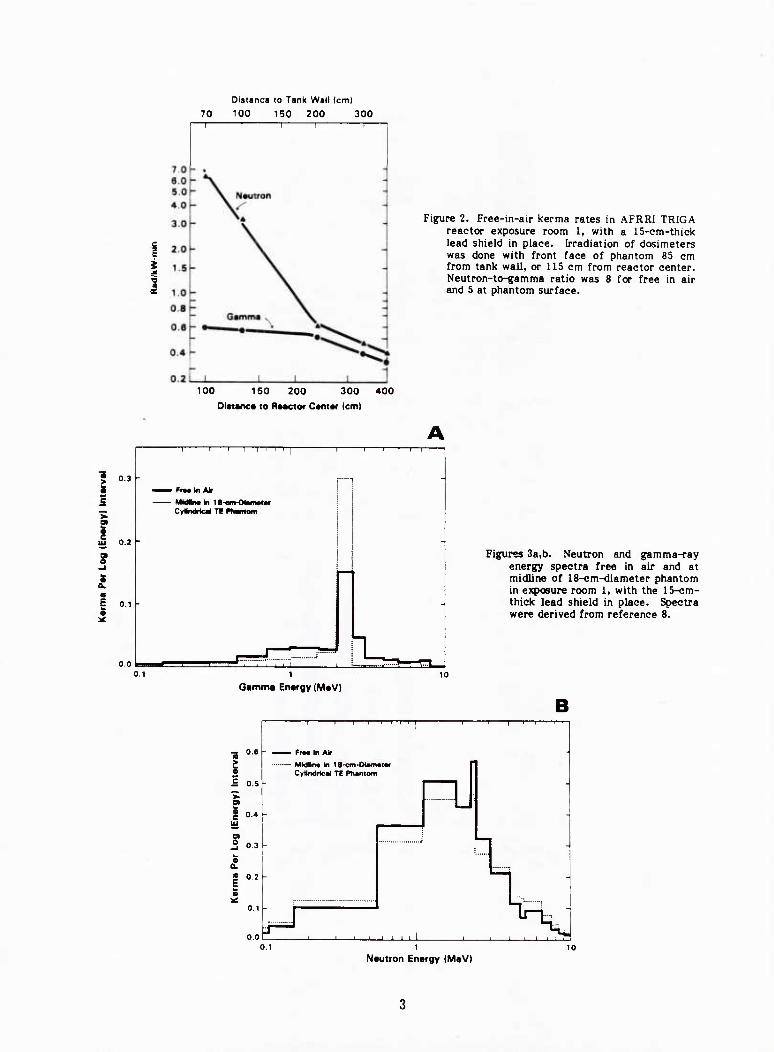
The eobalt-60 irradiations were carried out in a unilateral mode at 0.40 Gy/min. The dosimeters were free in air; that is, no phantom or backscattering material was used for the cobalt-60 irradiation. For reactor ii/adiation, the dosimeters were mounted on the surface of a cylindrical lucite phantom 30 cm in diameter and 60 cm tall. Eight dosimeters were arranged in a 10-cm-diameter array on a curved phantom surface facing the reactor. The entrance surface of the phantom was located 85 cm from the reactor tank wall, and a 15-cm-thick lead shield was positioned midway between the phantom and the tank wall. The dose rate on the phantom surface was 0.55 Gy/min with a neutron-to-gamma ratio of 5.0; i.e., 17% of the dose on the phantom surface was due to gamma rays. The neutron and gamma-ray free-in-air energy spectra and spatial variation are shown in Figures 2 and 3a,b.
70 -I—
Oiltanc* to Tank Wall Icml
100 150 200 300
100 1S0 200 300
Olrtanca to Raactor Canwr Icml
400
Figure 2. Free-in-air kerma rates in AFRRI TRIGA reactor exposure room 1, with a 15-cm-thick lead shield in place. Irradiation of dosimeters was done with front face of phantom 85 cm from tank wall, or 115 cm from reactor center. Neutron-to-gamma ratio was 8 for free in air and 5 at phantom surface.
A
1" ■ 1
^— FfMlnAlr
UJ 0.2 - _
i -i - • e 0.1 - i
r=J , r-J L,
0 1
Figures 3a,b. Neutron and gamma-ray energy spectra free in air and at midline of 18-cm-diameter phantom in exposure room 1, with the 15-cm- thick lead shield in place. Spectra were derived from reference 8.
Gamma Enargy (MaV)
y)I
nte
rval
o
o - _^_ FrM In Air
MhMkw In IScm-Otamctar CyHndjical Te Pti«nlon>
1 1 1—\—i i i
-
S 0.4 - *—•
I 0.3 1 » 02
0.1
-
1—■ '■
li-b 00
J i iii 1 1 1 1 1 '1*
1 1 1 1 1 1 .
Neutron Energy (MeV)

RESULTS
DOSIMETER READER
During initial tests, the calibration readings of the dosimeter reader were checked after every few dosimeters. These readings proved to be very constant, and the calibrations did not have to be adjusted if the unit had been powered ON for 24 hours. During the first 24 hours after turning the unit on, frequent calibration adjustments were necessary.
The reproducibility of sequential readings of the same dosimeter was within ±5% except for occasional aberrant readings markedly lower than expected. Because of this, the dose received by a dosimeter was usually taken to be the median of three sequential readings. The cause of the occasional low readings was not positively identified. Firmly holding the read-switch in position during the read cycle did lessen the number of aberrant readings.
DOSIMETER PREIRRADIATION READINGS
All nonirradiated dosimeters tested gave a nonzero dose reading. Individual dosimeter readings ranged from 20 to 60 rads total dose. Figures 4a,b,c summarize the readings of 70 nonirradiated dosimeters that were later used in further tests. These baseline or predose readings of the dosimeters could have been reduced by appropriate adjustments of the reader unit zero-levels. However, for the initial tests described in this report, no further zero-level adjustments were made.
0-4 5-9 10-14 15-IJ n-t* ti-n St-S4 35-3i 4«-44 45-49 50-54 55-59 80-04
Figure 4a. Readings of 70 nonirradiated dosimeters. Total dose: average 37.8 rads, SD 8.9 rads.

24 B . -
20 -
-
N 16 - U m
M
B 12 - E - n 8 -
| - 4 ■ 1 0 .11 | |
0-4 5-9 10-M 15-19 M-M M-W 39-34 35-39 40-44 45-49 50-54 55-59 60-64 ran
Figure 4b. Readings of 70 nonirradiated dosimeters. Gamma dose: average 19.4 rads, SD 6.8 rads.
0 4 5-9 10-14 15-19 W-24 M-29 30-34 35-39 40-44 45-49 50-54 55-59 60- rtdt
Figure 4c. Readings of 70 nonirradiated dosimeters. Neutron dose: average 18.5 rads, SD 7.1 rads.

Lower limits of detection (LLD) of the DT-236/PD dosimetry system can be inferred from observed variability of predose readings. Following the convention of U.S. Nuclear Regulatory Commission Regulatory Guide 8.14, "Personnel Neutron Dosimeters," the LLD is defined as follows:
LLD = 4.66 /N". S
where N is the number of dosimetry exchange periods in a calendar quarter (N = 1 in the present case) and S is the standard deviation (SD) of the normal background. Using the data in Figures 4a,b,c, the LLD of the DT-236/PD system is 33 rads neutron, 32 rads gamma, and 41 rads total dose.
COBALT-60 IRRADIATION
Dosimeters were irradiated with cobalt-60 gamma rays to doses of 500 rads, 100 rads, and 25 rads. The dosimeters were evaluated just after irradiation and at various times through the next 5 days. Figures 5a,b,c show the dosimeter gross readings uncorrected for baseline readings. The cobalt-60 data display the expected increase in phosphate glass gamma reading over the first day post- irradiation followed by a plateau or slow fading of readings. The variability of response between individual dosimeters, as determined from the five 500-rad dosimeters, was ±20% (2 SD) at most times, with larger variability of ±3096-40% observed within the first 2 hours after irradiation. The average gross response of the 500-rad dosimeters was higher than the delivered doses by +12% to +44% over the course of the measurement period. Correction for baseline readings would reduce this overresponse only slightly. •
lOOOr
800
600
■a
S.
400
200
.♦•
0.1 J
100.0 1.0 10.0 Time (hours)
Figure 5a. Readings of dosimeters irradiated with cobalt-60 at 500 rads. Data in Figures 5a,b,c are gross gamma readings, uncorrected for baseline preirradiation readings. Symbols represent separate dosimeters.

160
120
80
40
JL _L 0.1 100.0 1.0 10.0
Tim* (hour*) Figure 3b. Readings of dosimeters irradiated with cobalt-60 at 100 rads
1
60-
40-
20
QU'1 „«.•»• -"""•
0.1
/ ""••no
■^ ——•I
-L J_ J 100.0 1.0 10.0
Time (hours) Figure 5c. Readings of dosimeters irradiated with cobalt-60 at 25 rads

REACTOR IRRADIATION
Three reactor runs were performed with the delivered doses on the surface of the phantom listed in Table 1.
Table 1. Delivered Doses at Surface of Phantom
Dose (Rad)
Run Number Gamma Neutron Total
1 10 51 61
2 48 242 290
3 152 757 909
Eight dosimeters were irradiated in each run. The average response of the dosimeters is shown in Figures 6a,b,c. In these graphs, the average gamma, neutron, and total readings of nonirradiated dosimeters (Figure 2) have been subtracted. Thus the graphs represent net dosimeter readings. Error bars in these graphs indicate the 95% confidence interval (2 SD) determined from the eight dosimeters in each group.
The data displayed in Figures 6a,b,c show an overresponse to gamma radiation as observed for cobalt-60 irradiations and, generally, an underresponse to neutron radiation. These opposing biases resulted in total dose readings of the dosimeters that were reasonably accurate. The data also show the loss of neutron reading or fading with time after irradiation. The neutron fading over 13 days was 1096-15% for each of the three dose groups. It is of interest that the initial loss of neutron signal is at least partially compensated for by the increase in gamma signal, so that the total dose readings remain relatively constant for several days after irradiation.
Finally, Figures 6a,b,c show that the precision of the neutron dose readings was noticeably better than that of the gamma dose readings. For the two high-dose groups, the 95% confidence interval for the neutron readings was typically ±10%, and that for the gamma readings was typically ±20%. Precision of the total-dose readings was comparable to the neutron precision (±10%, 2 SD) for this high- neutron field. This contrasts with the ±20% total-dose precision obtained for the 500-rad gamma-only irradiations.

1200
1000
800
600
400
200
0
n—i—i—i—i—i—i—i—i—r—i—i—i—r
^s- ¥=i
'- i-i—I—i -i_i i i i i i i i i i—i i_i-
Total
320
280
240
0 2 4 6 8 10 12 14 Days
Neutron r 200 a
160 d
120
80
40
0
Gamma
■ Total
Neutron
■ Gamma
100 |—i—i—i—i—r—I—i—i—I—i—i—I—I—r
80
r 60 a
d 40
20
0
rr ■r~I
-i •''' 111111 I—I i-
Total
Neutron
Gamma
0 2 4 6 8 10 12 14 Days
Figures 6a,b,c. Readings of dosimeters irradiated with TRIGA reactor at (a) 909 rads, (b) 290 rads, and (c) 61 rads

DISCUSSION
Performance of the DT-236/PD and CP-696/UD dosimetry system has been studied in preliminary tests at AFRRI in cobalt-60 and in TRIGA-reactor radiation fields. The test results are relevant to the reproducibility of the dosimeter reader, the variability of readings among identically irradiated dosimeters, the fading or growth of dosimeter readings with time after irradiation, and the accuracy of dosimeter response in the AFRRI radiation fields.
The performance specifications (2, 3) for this system list ±40% accuracy at doses of 50-1000 rads and ±20-rad accuracy at 0-50 rads. The present tests showed the system to be capable of meeting these specifications and, with care, a level of accuracy of ±10% to 20% was achieved at high doses. At low doses, the accuracy of the system was limited by the ±20-rad (2 SD) variability in readings of nonirradiated dosimeters.
Factors found to improve the precision of dosimeter readings were (a) warm-up time of several hours for the reader unit, (b) sustained firm pressure on the mechanical switch that initiates the- read cycle, (c) triplicate readings of each dosimeter, (d) digital readout of the dose values, (e) proper accounting of dosimeter predose readings, and (f) waiting 2 hours after irradiation before reading the dosimeter. Although these practices were easily implemented in a laboratory setting, they may be totally impractical in field use of the system. Thus, in the field it seems likely that the specification of ±40% accuracy represents realistic performance of the system.
The test results described in this report represent the performance of a prototype dosimeter system. The final production version of the system, to be designated AN/PDR-75, will require similar tests to be performed. Further tests will also be needed to define the directional and energy response of the dosimeters as well as the performance of the system under extremes in ambient temperature.
REFERENCES
1. Becker, K. Solid State Dosimetry. CRC Press, Cleveland, 1973, pp. 141-173 and 225-231.
2. Basso, M. J. Response of the UK DT-236 Personnel Dosimeter to a Fast Pulsed Nuclear Reactor Radiation Environment. DELCS-K, MFR, Fort Monmouth, New Jersey, 1982.
3. Scott, W. H., et al. Dosimeter and bone marrow doses in tactical nuclear environments. SAI-133-80-269-LJ. Science Applications Inc., La Jolla, California, 1980.
4. U.S. Army Technical Manual for CP-696/UD Computer Indicator Radiac and DT-236/PD Detector Radiac. DEP TM 11-6665-236-12, Fort Monmouth, New Jersey, 1978.
5. Carter, R. E., and Verrelli, D. M. AFRRI cobalt whole-body irradiator. Technical Note TN73-3, Armed Forces Radiobiology Research Institute, Bethesda, Maryland, 1973.
10

6. Sholtis, J. A., and Moore, M. L. Reactor facility at Armed Forces Radio- biology Research Institute. Technical Report TR81-2, Armed Forces Radio- biology Research Institute, Bethesda, Maryland, 1981.
7. Goodman, L. J. A practical guide to ionization chamber dosimetry at the AFRRI reactor. Contract Report CR85-1, Armed Forces Radiobiology Research Institute, Bethesda, Maryland, 1985.
8. Verbinski, V. V., et al. Calculation of the neutron and gamma-ray environment in and around the AFRRI TRIGA reactor. DNA 5793F-2, Defense Nuclear Agency, Washington, DC, 1981.
11