meter / gauge system me–1 meter ... - … · meter / gauge system precaution 1. ... oil pressure...
TRANSCRIPT
METER – METER / GAUGE SYSTEM ME–1
E
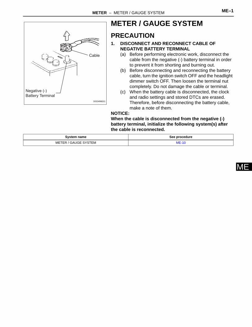
MMETER / GAUGE SYSTEMPRECAUTION1. DISCONNECT AND RECONNECT CABLE OF
NEGATIVE BATTERY TERMINAL(a) Before performing electronic work, disconnect the
cable from the negative (-) battery terminal in order to prevent it from shorting and burning out.
(b) Before disconnecting and reconnecting the battery cable, turn the ignition switch OFF and the headlight dimmer switch OFF. Then loosen the terminal nut completely. Do not damage the cable or terminal.
(c) When the battery cable is disconnected, the clock and radio settings and stored DTCs are erased. Therefore, before disconnecting the battery cable, make a note of them.
NOTICE:When the cable is disconnected from the negative (-) battery terminal, initialize the following system(s) after the cable is reconnected.
Negative (-)
Battery Terminal
Cable
D033496E01
System name See procedure
METER / GAUGE SYSTEM ME-10
ME–2 METER – METER / GAUGE SYSTEM
ME
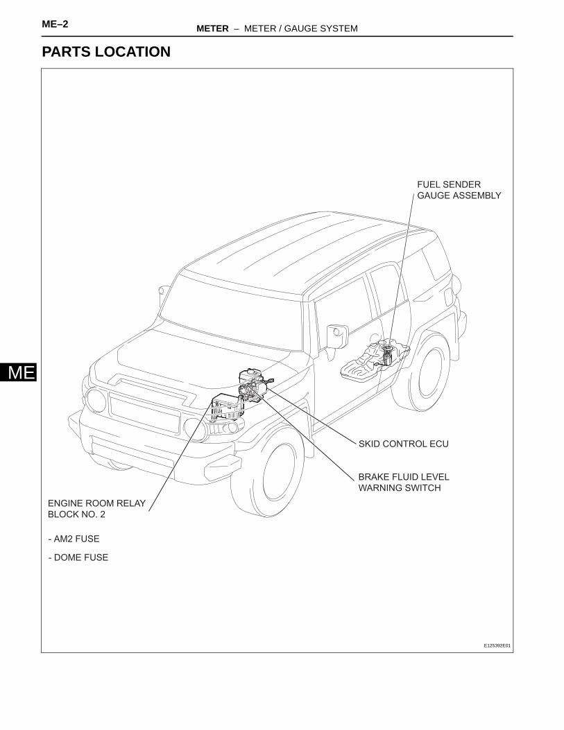
PARTS LOCATION
SKID CONTROL ECU
ENGINE ROOM RELAY
BLOCK NO. 2
- AM2 FUSE
- DOME FUSE
BRAKE FLUID LEVEL
WARNING SWITCH
FUEL SENDER
GAUGE ASSEMBLY
E125392E01
METER – METER / GAUGE SYSTEM ME–3
E
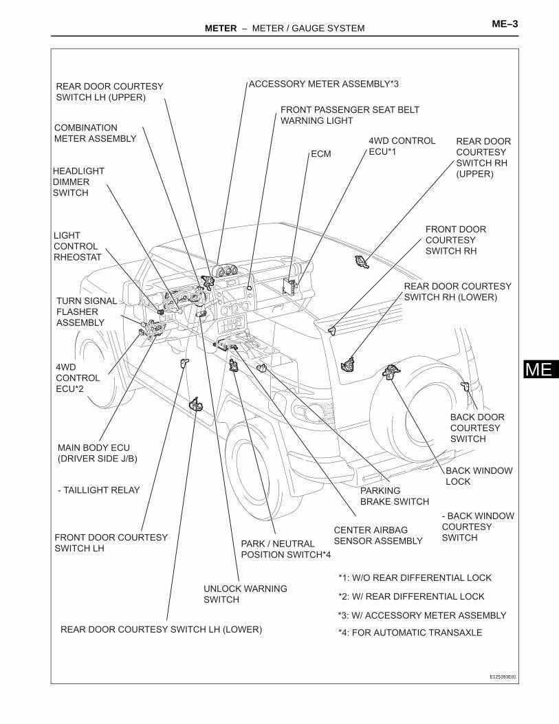
MHEADLIGHT
DIMMER
SWITCH
UNLOCK WARNING
SWITCH
CENTER AIRBAG
SENSOR ASSEMBLY
BACK DOOR
COURTESY
SWITCH
FRONT DOOR COURTESY
SWITCH LH
REAR DOOR COURTESY SWITCH LH (LOWER)
- TAILLIGHT RELAY
ECM
ACCESSORY METER ASSEMBLY*3
MAIN BODY ECU
(DRIVER SIDE J/B)
LIGHT
CONTROL
RHEOSTAT
4WD CONTROL
ECU*1
4WD
CONTROL
ECU*2
COMBINATION
METER ASSEMBLY REAR DOOR
COURTESY
SWITCH RH
(UPPER)
FRONT DOOR
COURTESY
SWITCH RH
REAR DOOR COURTESY
SWITCH RH (LOWER)
REAR DOOR COURTESY
SWITCH LH (UPPER)
PARK / NEUTRAL
POSITION SWITCH*4
PARKING
BRAKE SWITCH
TURN SIGNAL
FLASHER
ASSEMBLY
*1: W/O REAR DIFFERENTIAL LOCK
*2: W/ REAR DIFFERENTIAL LOCK
*3: W/ ACCESSORY METER ASSEMBLY
*4: FOR AUTOMATIC TRANSAXLE
FRONT PASSENGER SEAT BELT
WARNING LIGHT
BACK WINDOW
LOCK
- BACK WINDOW
COURTESY
SWITCH
E125393E01
ME–4 METER – METER / GAUGE SYSTEM
ME
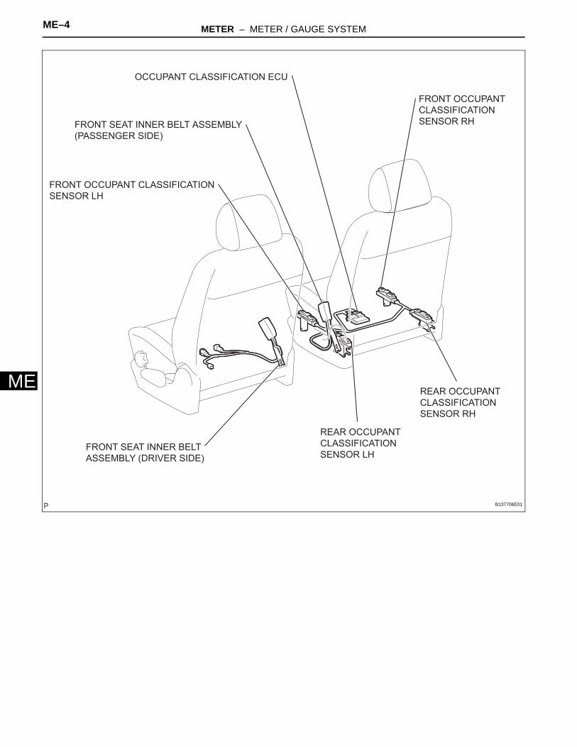
OCCUPANT CLASSIFICATION ECU
FRONT SEAT INNER BELT
ASSEMBLY (DRIVER SIDE)
FRONT OCCUPANT CLASSIFICATION
SENSOR LH
FRONT OCCUPANT
CLASSIFICATION
SENSOR RH
REAR OCCUPANT
CLASSIFICATION
SENSOR LH
REAR OCCUPANT
CLASSIFICATION
SENSOR RH
FRONT SEAT INNER BELT ASSEMBLY
(PASSENGER SIDE)
B137706E01

METER – METER / GAUGE SYSTEM ME–5
E
MCRANKSHAFT POSITION
SENSOR
ENGINE COOLANT
TEMPERATURE SENSOR
ENGINE OIL PRESSURE
SWITCH ASSEMBLY
*: FOR M/T
SPEED SENSOR*
E125395E01
ME–6 METER – METER / GAUGE SYSTEM
ME
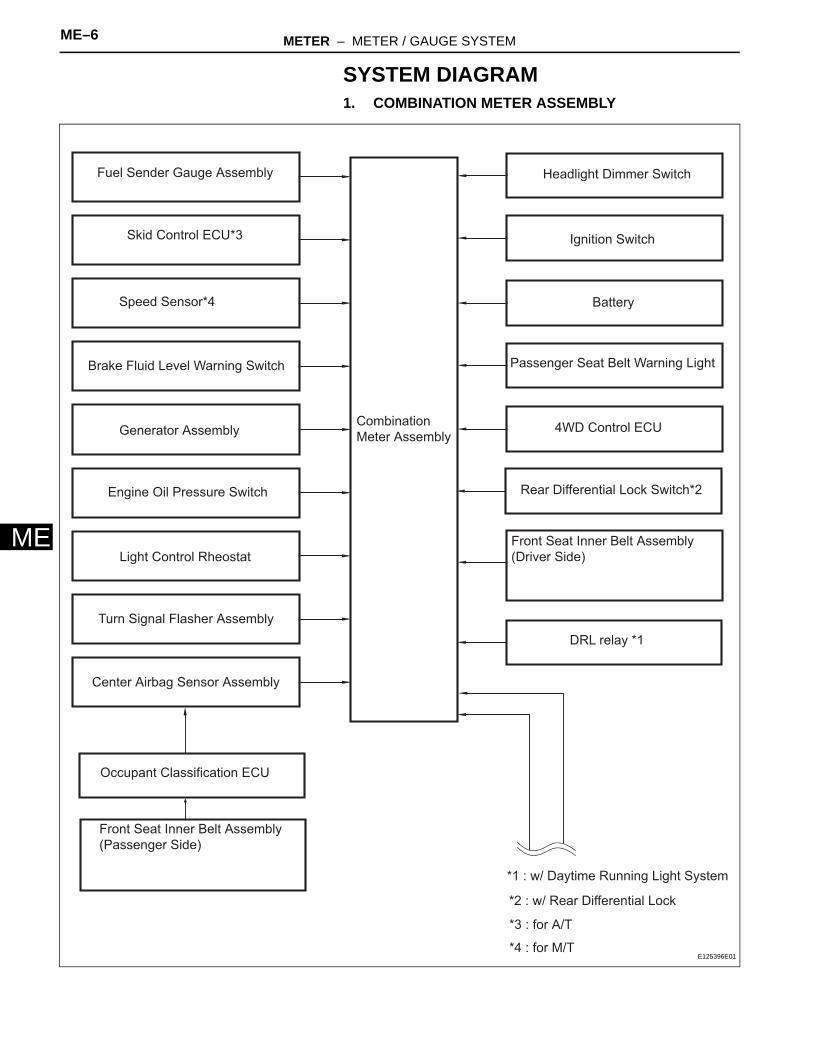
SYSTEM DIAGRAM1. COMBINATION METER ASSEMBLY
Fuel Sender Gauge Assembly
Skid Control ECU*3
Speed Sensor*4
Brake Fluid Level Warning Switch
Generator Assembly
Engine Oil Pressure Switch
Headlight Dimmer Switch
Ignition Switch
Battery
Passenger Seat Belt Warning Light
Light Control Rheostat
DRL relay *1
*1 : w/ Daytime Running Light System
Center Airbag Sensor Assembly
4WD Control ECU
Front Seat Inner Belt Assembly
(Driver Side)
*2 : w/ Rear Differential Lock
Rear Differential Lock Switch*2
Combination
Meter Assembly
Occupant Classification ECU
Front Seat Inner Belt Assembly
(Passenger Side)
Turn Signal Flasher Assembly
*3 : for A/T
*4 : for M/TE125396E01
METER – METER / GAUGE SYSTEM ME–7
E
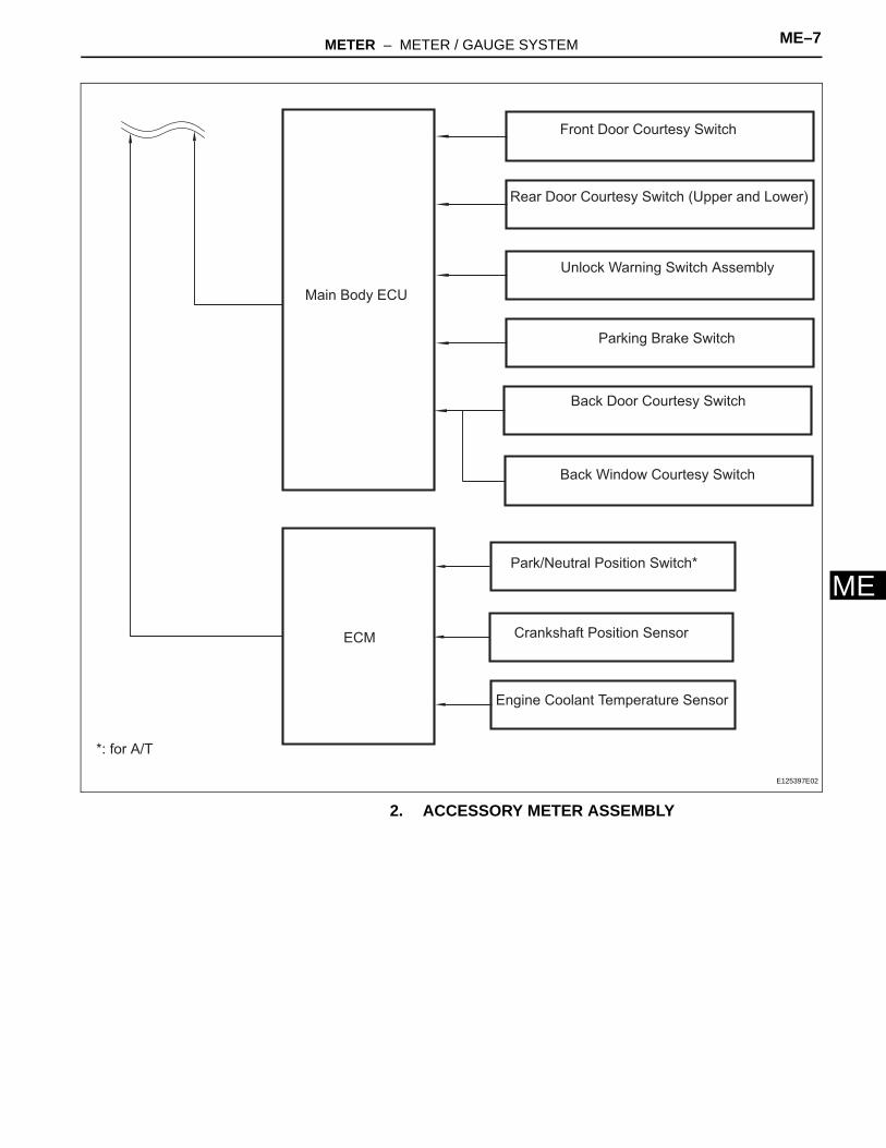
M2. ACCESSORY METER ASSEMBLY
Main Body ECU
ECM
Front Door Courtesy Switch
Rear Door Courtesy Switch (Upper and Lower)
Back Door Courtesy Switch
Unlock Warning Switch Assembly
Parking Brake Switch
Back Window Courtesy Switch
Park/Neutral Position Switch*
Crankshaft Position Sensor
Engine Coolant Temperature Sensor
*: for A/T
E125397E02
ME–8 METER – METER / GAUGE SYSTEM
ME
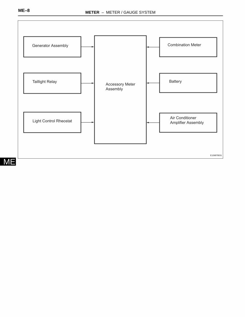
Generator Assembly
Taillight Relay
Light Control Rheostat
Combination Meter
Battery
Air Conditioner
Amplifier Assembly
Accessory Meter
Assembly
E126875E01
METER – METER / GAUGE SYSTEM ME–9
E
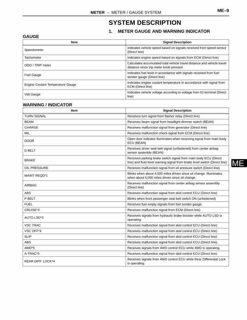
MSYSTEM DESCRIPTION1. METER GAUGE AND WARNING INDICATOR
GAUGE
WARNING / INDICATOR
Item Signal Description
Speedometer Indicates vehicle speed based on signals received from speed sensor (Direct line)
Tachometer Indicates engine speed based on signals from ECM (Direct line)
ODO / TRIP meter Calculates accumulated total vehicle travel distance and vehicle travel distance since trip meter knob pressed
Fuel Gauge Indicates fuel level in accordance with signals received from fuel sender gauge (Direct line)
Engine Coolant Temperature Gauge Indicates engine coolant temperature in accordance with signal from ECM (Direct line)
Volt Gauge Indicates vehicle voltage according to voltage from IG terminal (Direct line)
Item Signal Description
TURN SIGNAL Receives turn signal from flasher relay (Direct line)
BEAM Receives beam signal from headlight dimmer switch (BEAN)
CHARGE Receives malfunction signal from generator (Direct line)
MIL Receives malfunction check signal from ECM (Direct line)
DOOR Open door indicator illuminates when receiving signal from main body ECU (BEAN)
D BELT Receives driver seat belt signal (unfastened) from center airbag sensor assembly (BEAN)
BRAKE Receives parking brake switch signal from main body ECU (Direct line) and fluid level warning signal from brake level switch (Direct line)
OIL PRESSURE Receives malfunction signal from oil pressure switch (Direct line)
MAINT REQD*1 Blinks when about 4,500 miles driven since oil change. Illuminates when about 5,000 miles driven since oil change.
AIRBAG Receives malfunction signal from center airbag sensor assembly (Direct line)
ABS Receives malfunction signal from skid control ECU (Direct line)
P BELT Blinks when front passenger seat belt switch ON (unfastened)
FUEL Receives fuel empty signals from fuel sender gauge.
CRUISE*2 Receives malfunction signal from ECM (Direct line)
AUTO LSD*3 Receives signals from hydraulic brake booster while AUTO LSD is operating.
VSC TRAC Receives malfunction signal from skid control ECU (Direct line)
VSC OFF*4 Receives malfunction signal from skid control ECU (Direct line)
SLIP Receives malfunction signal from skid control ECU (Direct line)
ABS Receives malfunction signal from skid control ECU (Direct line)
4WD*5 Receives signals from 4WD control ECU while 4WD is operating.
A-TRAC*5 Receives malfunction signal from skid control ECU (Direct line)
REAR DIFF. LOCK*4 Receives signals from 4WD control ECU while Rear Differential Lock is operating.
ME–10 METER – METER / GAUGE SYSTEM
ME
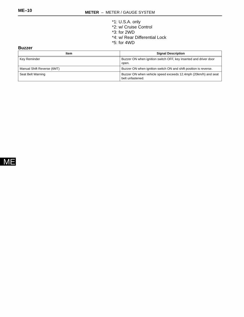
*1: U.S.A. only*2: w/ Cruise Control*3: for 2WD*4: w/ Rear Differential Lock*5: for 4WD
BuzzerItem Signal Description
Key Reminder Buzzer ON when ignition switch OFF, key inserted and driver door open.
Manual Shift Reverse (6MT) Buzzer ON when ignition switch ON and shift position is reverse.
Seat Belt Warning Buzzer ON when vehicle speed exceeds 12.4mph (20km/h) and seat belt unfastened.
METER – METER / GAUGE SYSTEM ME–11
E
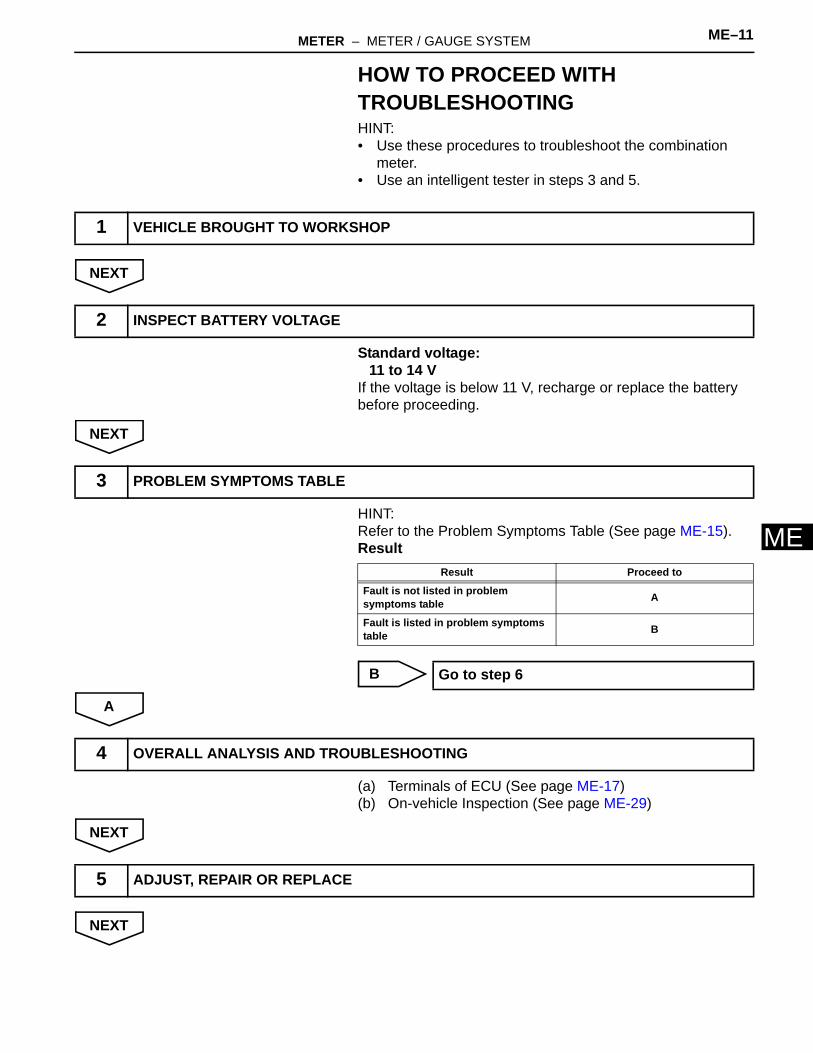
MHOW TO PROCEED WITH TROUBLESHOOTINGHINT:• Use these procedures to troubleshoot the combination
meter.• Use an intelligent tester in steps 3 and 5.
NEXT
Standard voltage:11 to 14 V
If the voltage is below 11 V, recharge or replace the battery before proceeding.
NEXT
HINT:Refer to the Problem Symptoms Table (See page ME-15).Result
B
A
(a) Terminals of ECU (See page ME-17)(b) On-vehicle Inspection (See page ME-29)
NEXT
NEXT
1 VEHICLE BROUGHT TO WORKSHOP
2 INSPECT BATTERY VOLTAGE
3 PROBLEM SYMPTOMS TABLE
Result Proceed to
Fault is not listed in problem symptoms table A
Fault is listed in problem symptoms table B
Go to step 6
4 OVERALL ANALYSIS AND TROUBLESHOOTING
5 ADJUST, REPAIR OR REPLACE
ME–12 METER – METER / GAUGE SYSTEM
ME
NEXT
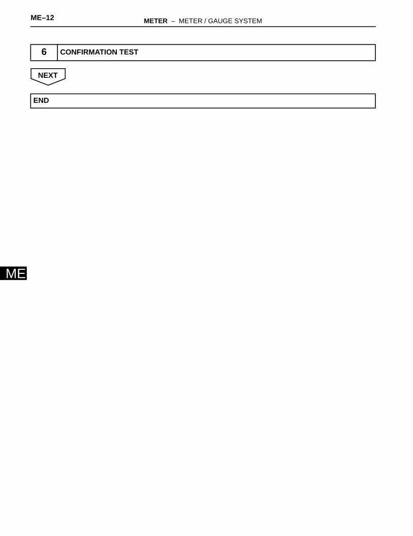
6 CONFIRMATION TEST
END
METER – METER / GAUGE SYSTEM ME–13
E
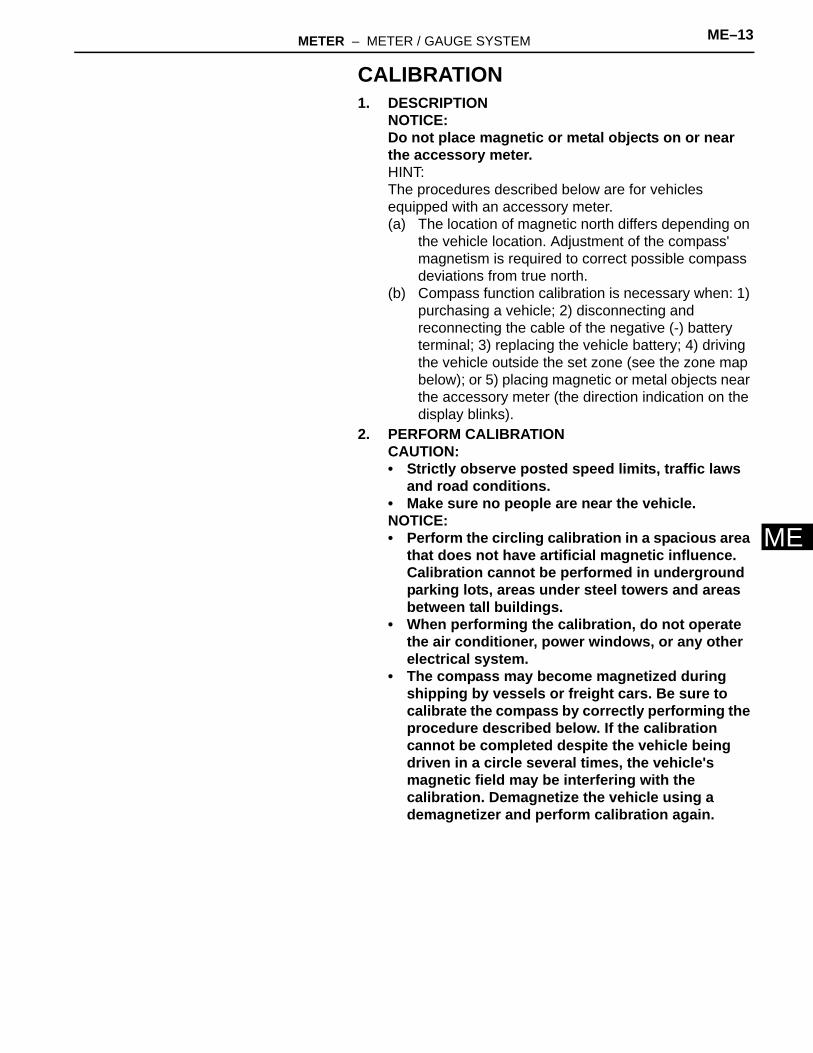
MCALIBRATION1. DESCRIPTION
NOTICE:Do not place magnetic or metal objects on or near the accessory meter.HINT:The procedures described below are for vehicles equipped with an accessory meter.(a) The location of magnetic north differs depending on
the vehicle location. Adjustment of the compass' magnetism is required to correct possible compass deviations from true north.
(b) Compass function calibration is necessary when: 1) purchasing a vehicle; 2) disconnecting and reconnecting the cable of the negative (-) battery terminal; 3) replacing the vehicle battery; 4) driving the vehicle outside the set zone (see the zone map below); or 5) placing magnetic or metal objects near the accessory meter (the direction indication on the display blinks).
2. PERFORM CALIBRATIONCAUTION:• Strictly observe posted speed limits, traffic laws
and road conditions. • Make sure no people are near the vehicle. NOTICE:• Perform the circling calibration in a spacious area
that does not have artificial magnetic influence. Calibration cannot be performed in underground parking lots, areas under steel towers and areas between tall buildings.
• When performing the calibration, do not operate the air conditioner, power windows, or any other electrical system.
• The compass may become magnetized during shipping by vessels or freight cars. Be sure to calibrate the compass by correctly performing the procedure described below. If the calibration cannot be completed despite the vehicle being driven in a circle several times, the vehicle's magnetic field may be interfering with the calibration. Demagnetize the vehicle using a demagnetizer and perform calibration again.
ME–14 METER – METER / GAUGE SYSTEM
ME
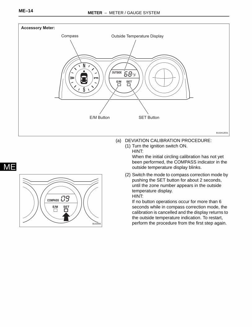
(a) DEVIATION CALIBRATION PROCEDURE:(1) Turn the ignition switch ON.
HINT:When the initial circling calibration has not yet been performed, the COMPASS indicator in the outside temperature display blinks.
(2) Switch the mode to compass correction mode by pushing the SET button for about 2 seconds, until the zone number appears in the outside temperature display.HINT:If no button operations occur for more than 6 seconds while in compass correction mode, the calibration is cancelled and the display returns to the outside temperature indication. To restart, perform the procedure from the first step again.
Compass
E/M Button SET Button
Outside Temperature Display
Accessory Meter:
B133412E01
B133406
METER – METER / GAUGE SYSTEM ME–15
E
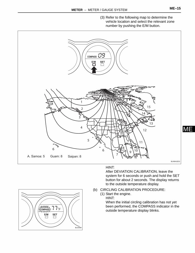
M(3) Refer to the following map to determine the vehicle location and select the relevant zone number by pushing the E/M button.
HINT:After DEVIATION CALIBRATION, leave the system for 6 seconds or push and hold the SET button for about 2 seconds. The display returns to the outside temperature display.
(b) CIRCLING CALIBRATION PROCEDURE:(1) Start the engine.
HINT:When the initial circling calibration has not yet been performed, the COMPASS indicator in the outside temperature display blinks.
6 67
5
4
1
2
3
89 10
11
12
13
14
15
A. Samoa: 5 Saipan: 8Guam: 8
B145641E01
B133408

ME–16 METER – METER / GAUGE SYSTEM
ME
(2) Switch the mode to compass correction mode by pushing the SET button for about 2 seconds, until the zone number appears in the outside temperature display.HINT:If no button operations occur for more than 6 seconds while in compass correction mode, calibration is cancelled and the display returns to the outside temperature indication. To restart, perform the procedure from the first step again.
(3) Push the SET button again to change the mode to turn correction mode.HINT:While in correction mode, the indication bars move as shown in the illustration.
(4) If there is sufficient space to drive the vehicle in a circle, perform the following procedure:1. Drive the vehicle in a full circle within 2
minutes, at a vehicle speed of 5mph (8km/h) or lower, as shown in the illustration.
NOTICE:• Do not perform the circling calibration of
the compass in a place where the earth's magnetic field is subject to interference by artificial magnetic fields (underground parking, under a steel tower, between buildings, roof parking, near a crossing, near a large vehicle, etc.).
• During the calibration, do not operate any electric systems (power window, etc.) as they may interfere with the calibration.
B133406
B133389
B133390
METER – METER / GAUGE SYSTEM ME–17
E
MHINT:• When the compass display returns to the
outside temperature display, the calibration is complete.
• When the circling calibration fails, "Er" is displayed for about 2 seconds and then the COMPASS indicator flashes.
• If the correct direction is not displayed after driving the vehicle as specified, change the vehicle location.
• To cancel the calibration before completion, push the SET button for about 2 seconds.
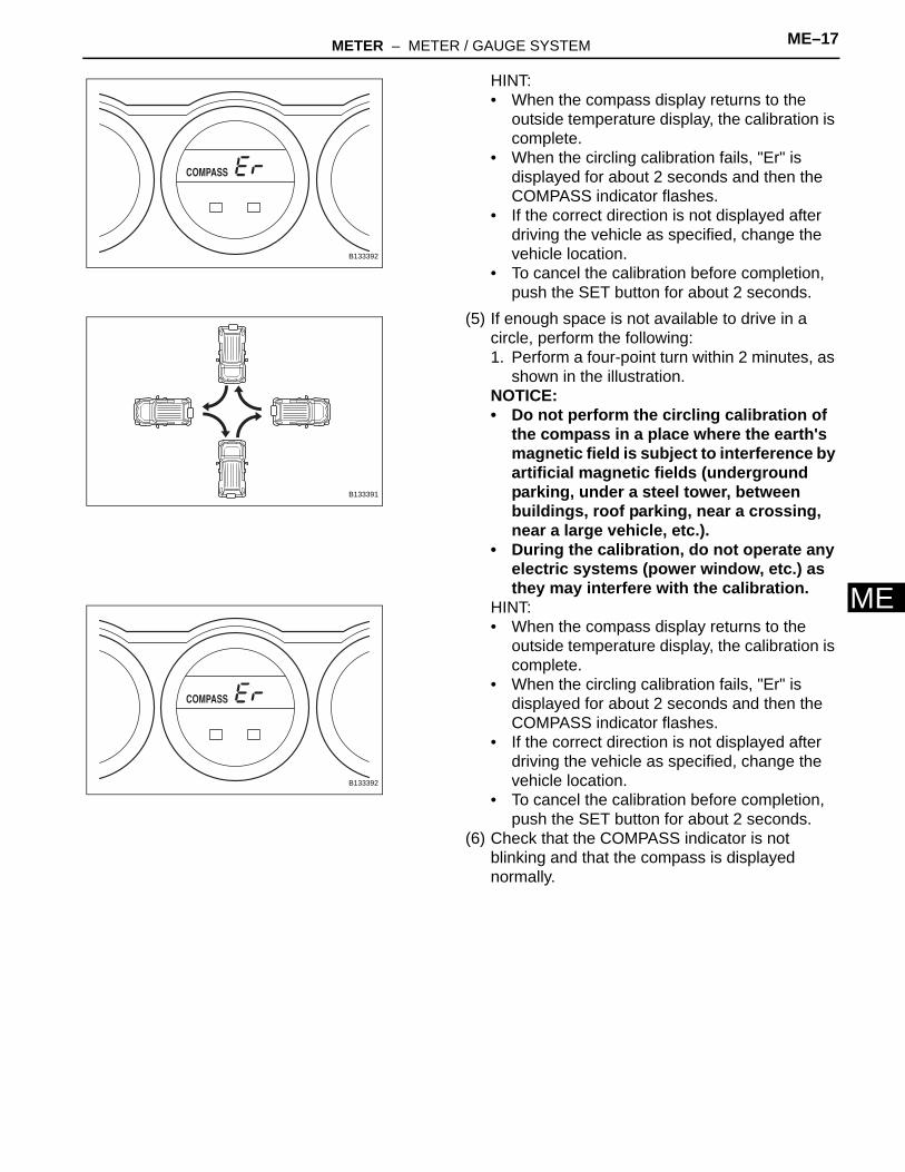
(5) If enough space is not available to drive in a circle, perform the following:1. Perform a four-point turn within 2 minutes, as
shown in the illustration.NOTICE:• Do not perform the circling calibration of
the compass in a place where the earth's magnetic field is subject to interference by artificial magnetic fields (underground parking, under a steel tower, between buildings, roof parking, near a crossing, near a large vehicle, etc.).
• During the calibration, do not operate any electric systems (power window, etc.) as they may interfere with the calibration.
HINT:• When the compass display returns to the
outside temperature display, the calibration is complete.
• When the circling calibration fails, "Er" is displayed for about 2 seconds and then the COMPASS indicator flashes.
• If the correct direction is not displayed after driving the vehicle as specified, change the vehicle location.
• To cancel the calibration before completion, push the SET button for about 2 seconds.
(6) Check that the COMPASS indicator is not blinking and that the compass is displayed normally.
B133392
B133391
B133392
ME–18 METER – METER / GAUGE SYSTEM
ME
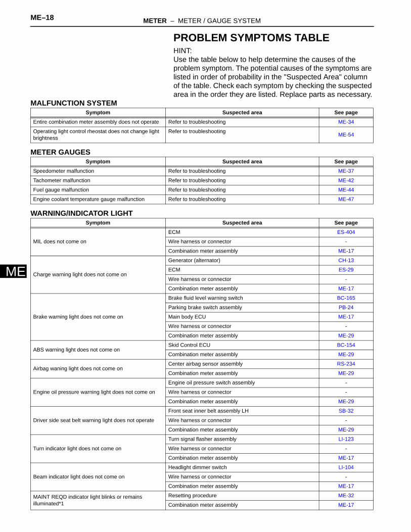
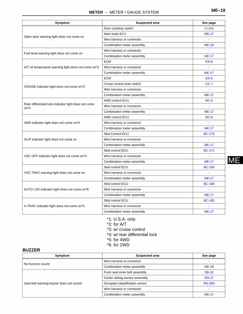
PROBLEM SYMPTOMS TABLEHINT:Use the table below to help determine the causes of the problem symptom. The potential causes of the symptoms are listed in order of probability in the "Suspected Area" column of the table. Check each symptom by checking the suspected area in the order they are listed. Replace parts as necessary.
MALFUNCTION SYSTEM
METER GAUGES
WARNING/INDICATOR LIGHT
Symptom Suspected area See page
Entire combination meter assembly does not operate Refer to troubleshooting ME-34
Operating light control rheostat does not change light brightness
Refer to troubleshooting ME-54
Symptom Suspected area See page
Speedometer malfunction Refer to troubleshooting ME-37
Tachometer malfunction Refer to troubleshooting ME-42
Fuel gauge malfunction Refer to troubleshooting ME-44
Engine coolant temperature gauge malfunction Refer to troubleshooting ME-47
Symptom Suspected area See page
MIL does not come on
ECM ES-404
Wire harness or connector -
Combination meter assembly ME-17
Charge warning light does not come on
Generator (alternator) CH-13
ECM ES-29
Wire harness or connector -
Combination meter assembly ME-17
Brake warning light does not come on
Brake fluid level warning switch BC-165
Parking brake switch assembly PB-24
Main body ECU ME-17
Wire harness or connector -
Combination meter assembly ME-29
ABS warning light does not come onSkid Control ECU BC-154
Combination meter assembly ME-29
Airbag waning light does not come onCenter airbag sensor assembly RS-234
Combination meter assembly ME-29
Engine oil pressure warning light does not come on
Engine oil pressure switch assembly -
Wire harness or connector -
Combination meter assembly ME-29
Driver side seat belt warning light does not operate
Front seat inner belt assembly LH SB-32
Wire harness or connector -
Combination meter assembly ME-29
Turn indicator light does not come on
Turn signal flasher assembly LI-123
Wire harness or connector -
Combination meter assembly ME-17
Beam indicator light does not come on
Headlight dimmer switch LI-104
Wire harness or connector -
Combination meter assembly ME-17
MAINT REQD indicator light blinks or remains illuminated*1
Resetting procedure ME-32
Combination meter assembly ME-17
METER – METER / GAUGE SYSTEM ME–19
E
M*1: U.S.A. only*2: for A/T*3: w/ cruise control*4: w/ rear differential lock*5: for 4WD*6: for 2WD
BUZZER
Open door warning light does not come on
Door courtesy switch LI-114
Main body ECU ME-17
Wire harness or connector -
Combination meter assembly ME-29
Fuel level warning light does not come onWire harness or connector -
Combination meter assembly ME-17
A/T oil temperature warning light does not come on*2
ECM ES-6
Wire harness or connector -
Combination meter assembly ME-17
CRUISE indicator light does not come on*3
ECM ES-6
Cruise control main switch CC-7
Wire harness or connector -
Combination meter assembly ME-17
Rear differential lock indicator light does not come on*4
4WD control ECU BC-6
Wire harness or connector -
Combination meter assembly ME-17
4WD indicator light does not come on*5
4WD control ECU BC-6
Wire harness or connector -
Combination meter assembly ME-17
SLIP indicator light does not come on
Skid Control ECU BC-175
Wire harness or connector -
Combination meter assembly ME-17
VSC OFF indicator light does not come on*4
Skid control ECU BC-171
Wire harness or connector -
Combination meter assembly ME-17
VSC TRAC warning light does not come on
Skid control ECU BC-159
Wire harness or connector -
Combination meter assembly ME-17
AUTO LSD indicator light does not come on*6
Skid control ECU BC-180
Wire harness or connector -
Combination meter assembly ME-17
A-TRAC indicator light does not come on*5
Skid control ECU BC-185
Wire harness or connector -
Combination meter assembly ME-17
Symptom Suspected area See page
Symptom Suspected area See page
No buzzers soundWire harness or connector -
Combination meter assembly ME-49
Seat belt warning buzzer does not sound
Front seat inner belt assembly SB-32
Center airbag sensor assembly RS-27
Occupant classification sensor RS-250
Wire harness or connector -
Combination meter assembly ME-17
ME–20 METER – METER / GAUGE SYSTEM
ME
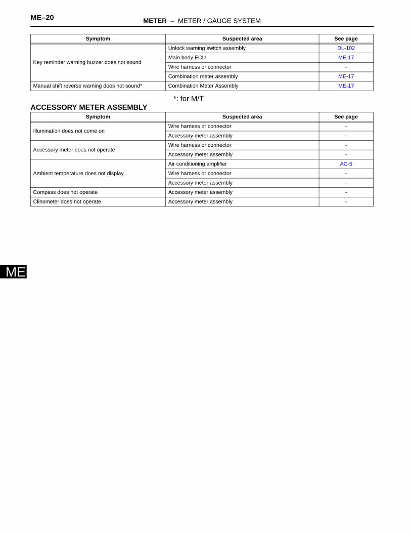
*: for M/TACCESSORY METER ASSEMBLY
Key reminder warning buzzer does not sound
Unlock warning switch assembly DL-102
Main body ECU ME-17
Wire harness or connector -
Combination meter assembly ME-17
Manual shift reverse warning does not sound* Combination Meter Assembly ME-17
Symptom Suspected area See page
Symptom Suspected area See page
Illumination does not come onWire harness or connector -
Accessory meter assembly -
Accessory meter does not operateWire harness or connector -
Accessory meter assembly -
Ambient temperature does not display
Air conditioning amplifier AC-5
Wire harness or connector -
Accessory meter assembly -
Compass does not operate Accessory meter assembly -
Clinometer does not operate Accessory meter assembly -
METER – METER / GAUGE SYSTEM ME–21
E
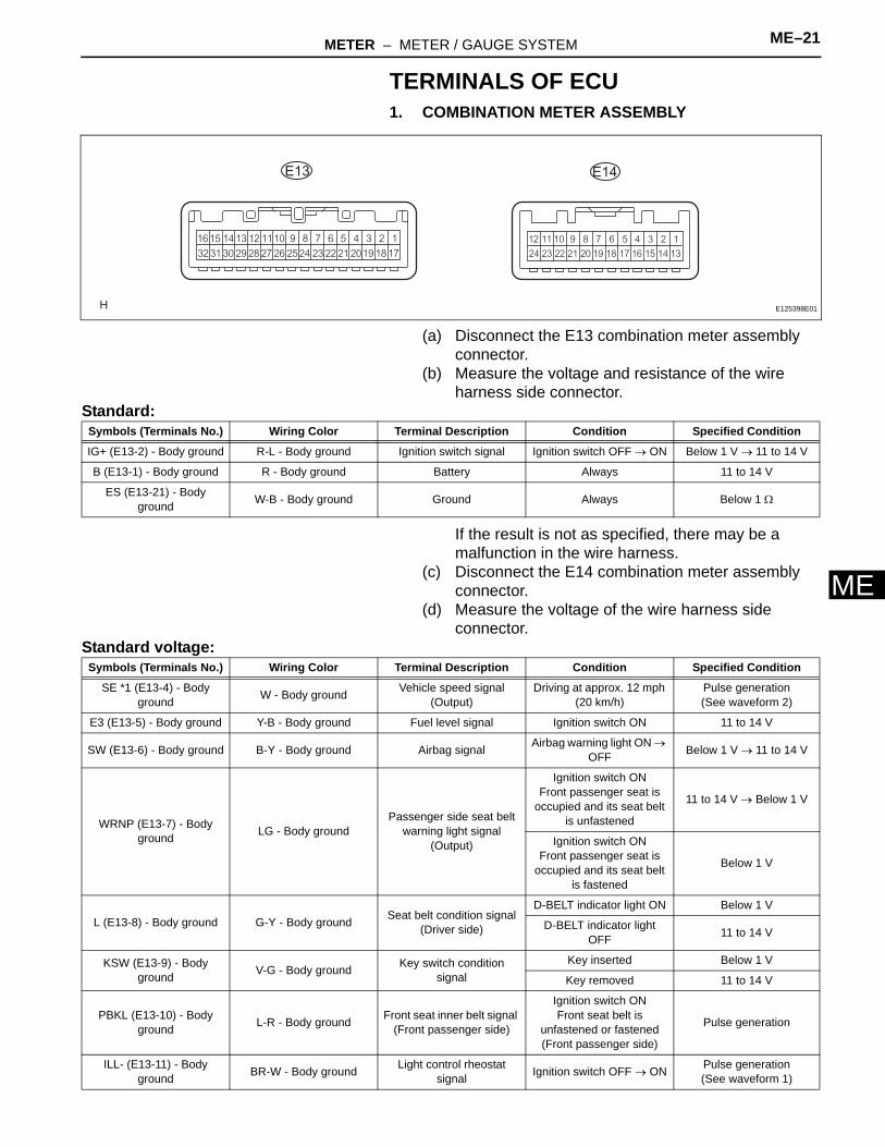
MTERMINALS OF ECU1. COMBINATION METER ASSEMBLY
(a) Disconnect the E13 combination meter assembly connector.
(b) Measure the voltage and resistance of the wire harness side connector.
Standard:
If the result is not as specified, there may be a malfunction in the wire harness.
(c) Disconnect the E14 combination meter assembly connector.
(d) Measure the voltage of the wire harness side connector.
Standard voltage:
E14E13
E125398E01
Symbols (Terminals No.) Wiring Color Terminal Description Condition Specified Condition
IG+ (E13-2) - Body ground R-L - Body ground Ignition switch signal Ignition switch OFF → ON Below 1 V → 11 to 14 V
B (E13-1) - Body ground R - Body ground Battery Always 11 to 14 V
ES (E13-21) - Body ground W-B - Body ground Ground Always Below 1 Ω
Symbols (Terminals No.) Wiring Color Terminal Description Condition Specified Condition
SE *1 (E13-4) - Body ground W - Body ground Vehicle speed signal
(Output)Driving at approx. 12 mph
(20 km/h)Pulse generation(See waveform 2)
E3 (E13-5) - Body ground Y-B - Body ground Fuel level signal Ignition switch ON 11 to 14 V
SW (E13-6) - Body ground B-Y - Body ground Airbag signal Airbag warning light ON → OFF Below 1 V → 11 to 14 V
WRNP (E13-7) - Body ground LG - Body ground
Passenger side seat belt warning light signal
(Output)
Ignition switch ONFront passenger seat is
occupied and its seat belt is unfastened
11 to 14 V → Below 1 V
Ignition switch ONFront passenger seat is
occupied and its seat belt is fastened
Below 1 V
L (E13-8) - Body ground G-Y - Body ground Seat belt condition signal (Driver side)
D-BELT indicator light ON Below 1 V
D-BELT indicator light OFF 11 to 14 V
KSW (E13-9) - Body ground V-G - Body ground Key switch condition
signalKey inserted Below 1 V
Key removed 11 to 14 V
PBKL (E13-10) - Body ground L-R - Body ground Front seat inner belt signal
(Front passenger side)
Ignition switch ONFront seat belt is
unfastened or fastened (Front passenger side)
Pulse generation
ILL- (E13-11) - Body ground BR-W - Body ground Light control rheostat
signal Ignition switch OFF → ON Pulse generation(See waveform 1)
ME–22 METER – METER / GAUGE SYSTEM
ME
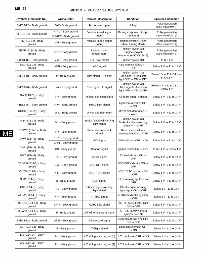
S (E13-12) - Body ground B-W - Body ground Tachometer signal Idling Pulse generation(See waveform 2)
SI (E13-13) - Body groundR-Y*1 - Body ground Vehicle speed signal
(Input)Driving at approx. 12 mph
(20 km/h)Pulse generation(See waveform 2)GR-R*2 - Body ground
+S (E13-14) - Body ground V-R - Body ground Vehicle Speed signal
(Input)Ignition switch ON and wheel turning slowly
Pulse generation(See waveform 2)
TEMP (E13-15) - Body ground BR-B - Body ground Engine coolant
temperature
Ignition switch ONEngine coolant
temperature 90°C(194°F)
Pulse generation(See waveform 3)
L (E13-16) - Body ground V-W - Body ground Fuel level signal Ignition switch ON 11 to 14 V
ESC (E13-17) - Body ground LG-R - Body ground ABS signal ABS warning light ON →
OFF Below 1 V → 11 to 14 V
B (E13-18) - Body ground P - Body ground Turn signal RH signalIgnition switch ON
Turn signal RH indicator light OFF → ON → OFF
Below 1 V → 11 to 14 V → Below 1 V
B (E13-20) - Body ground L-W - Body ground Turn signal LH signalIgnition switch ON
Turn signal LH indicator light OFF → ON → OFF
Below 1 V → 11 to 14 V → Below 1 V
SW (E13-23) - Body ground V-Y - Body ground All door condition signal All doors open → closed Below 1 V → 11 to 14 V
+ (E13-26) - Body ground R-W - Body ground HEAD light signal Light control switch OFF → ON Below 1 V → 11 to 14 V
DOOR (E13-29) - Body ground W-L - Body ground Driver side door open Driver side door open →
closed Below 1 V → 11 to 14 V
PKB (E13-31) - Body ground B-L - Body ground Brake fluid level warning
light signal
Ignition switch ONBrake fluid level warning
light ON → OFFBelow 1 V → 11 to 14 V
PRSW*8 (E14-1) - Body ground L-Y - Body ground Rear differential lock
signalRear differential lock
warning light ON → OFF Below 1 V → 11 to 14 V
SW*4 (E14-2) - Body ground
R-L*3 - Body ground4WD signal 4WD indicator OFF → ON Below 1 V → 11 to 14 V
GR*1 - Body ground
CHG- (E14-3) - Body ground GR - Body ground Change signal Ignition switch ON → OFF 11 to 14 V → Below 1 V
A/D*6 (E14-4) - Body ground P-G - Body ground Cruise signal Cruise indicator ON →
OFF Below 1 V → 11 to 14 V
TROF*8 (E14-5) - Body ground L-W - Body ground VSC OFF signal VSC OFF indicator ON →
OFF Below 1 V → 11 to 14 V
VSCW (E14-6) - Body ground Y-R - Body ground VSC TRAC signal VSC TRAC indicator ON
→ OFF Below 1 V → 11 to 14 V
SLIP (E14-7) - Body ground R - Body ground SLIP signal SLIP warning light ON →
OFF Below 1 V → 11 to 14 V
CHK (E14-8) - Body ground R-B - Body ground Check engine warning
light signalCheck engine warning light signal ON → OFF Below 1V→11 to 14 V
ATRA*7 (E14-9) - Body ground Y-V - Body ground A-TRAC signal A-TRAC indicator light ON
→ OFF Below 1V→11 to 14 V
ALSD*5 (E14-10) - Body ground BR-Y - Body ground AUTO LSD signal AUTO LSD indicator light
ON → OFF Below 1 V → 11 to 14 V
OILW*2 (E14-11) - Body ground P - Body ground A/T oil temperature signal A/T OIL TEMP warning
light ON → OFF Below 1 V → 11 to 14 V
S (E14-12) - Body ground LG-B - Body ground Oil pressure signal Oil pressure warning light ON → OFF Below 1 V → 11 to 14 V
ILL+ (E14-13) - Body ground G - Body ground Taillight signal Light control switch OFF
→ ON Below 1 V→11 to 14 V
L*2 (E14-14) - Body ground B-L - Body ground A/T shift position signal (L) A/T L indicator OFF → ON Below 1 V→11 to 14 V
2*2 (E14-15) - Body ground P-L - Body ground A/T shift position signal (2) A/T 2 indicator OFF → ON Below 1 V→11 to 14 V
Symbols (Terminals No.) Wiring Color Terminal Description Condition Specified Condition

METER – METER / GAUGE SYSTEM ME–23
E
M*1: for M/T*2: for A/T (2WD and 4WD)*3: for A/T (4WD only)*4: for 4WD*5: for 2WD*6: w/ cruise control*7: w/ active traction control (4WD only)*8: w/ rear differential lockHINT:If the result is not as specified, the combination meter assembly may be malfunctioning.(1) Waveform 1: Using an oscilloscope
(2) Waveform 2: Using an oscilloscope
HINT:As the vehicle speed increases, the cycle of the signal waveform narrows.
3*2 (E14-16) - Body ground W-R - Body ground A/T shift position signal (3) A/T 3 indicator OFF → ON Below 1 V→11 to 14 V
4*2 (E14-17) - Body ground B-O - Body ground A/T shift position signal (4) A/T 4 indicator OFF → ON Below 1 V→11 to 14 V
D*2 (E14-18) - Body ground R-G - Body ground A/T shift position signal
(D)A/T D indicator OFF →
ON Below 1 V→11 to 14 V
N*2 (E14-19) - Body ground G-W - Body ground A/T shift position signal
(N)A/T N indicator OFF →
ON Below 1 V→11 to 14 V
R*2 (E14-20) - Body ground R-Y - Body ground A/T shift position signal
(R)A/T R indicator OFF →
ON Below 1 V→11 to 14 V
R*1 (E14-20) - Body ground R-Y - Body ground M/T shift position signal
(R)M/T shift warning buzzer
OFF → ON Below 1 V→11 to 14 V
P*2 (E14-21) - Body ground Y-B - Body ground A/T shift position signal (P) A/T P indicator OFF → ON Below 1 V→11 to 14 V
ATP*3 (E14-22) - Body ground W - Body ground Transfer indicator switch
neutral position signal A/T P indicator OFF → ON Below 1 V→11 to 14 V
Symbols (Terminals No.) Wiring Color Terminal Description Condition Specified Condition
GND
A005138E12
Terminal Connections ILL- (E13-11) - Body Ground
Tool Setting 5V / DIV, 50 ms / DIV
Condition Ignition switch ON
GND
E115032E02
Terminal Connections
SE (E13-4) - Body GroundS (E13-12) - Body GroundSI (E13-13) - Body Ground+S (E13-14) - Body Ground
Tool Setting 5V / DIV, 20ms / DIV
Condition Driving at approximately 12mph (20km/h)

ME–24 METER – METER / GAUGE SYSTEM
ME
(e) Waveform 3: Using an oscilloscope
HINT:A changes in accordance with the engine coolant temperature.
2. ACCESSORY METER ASSEMBLY
(a) Disconnect the F1 accessory meter assembly connector.
(b) Measure the voltage and resistance of the wire harness side connector.
Standard:
HINT:If the result is not as specified, the accessory meter assembly may be malfunctioning.
GND
E050693E05
Tool setting 5 V/DIV., 0.1 sec./DIV
Vehicle condition Ignition switch ON
Coolant temperature Below 30° Approximately
75°C Above 90°
A Approximately 16 ms
Approximately 204 ms
Approximately 262 ms
F1
E125402E01
Symbols (Terminals No.) Wiring Color Terminal Description Condition Specified Condition
+B (F1-1) - Body ground R - Body ground Battery Always 11 to 14 V
ACC (F1-2) - Body ground GR - Body ground ACC Ignition switch OFF → ACC Below 1 V → 11 to 14 V
IG+ (F1-3) - Body ground Y-R - Body ground Ignition switch signal Ignition switch OFF → ON Below 1 V → 11 to 14 V
DMIN (F1-4) - Body ground R-L - Body ground Air conditioning amplifier
signal Ignition switch OFF → ON Below 1 V → 11 to 14 V
ILL+ (F1-6) - Body ground G - Body ground Taillight signal Light control switch OFF → ON Below 1 V → 11 to 14 V
ILL- (F1-7) - Body ground BR-W - Body ground Light control rheostat signal Ignition switch OFF → ON Pulse generation
(See waveform 1)
SI (F1-8) - Body ground V-R - Body ground Combination meter signal Driving at approx. 3.1 mph (5 km/h) 1 V → 9 V → 1 V
E (F1-9) - Body ground W-B - Body ground Ground Always Below 1 Ω
METER – METER / GAUGE SYSTEM ME–25
E
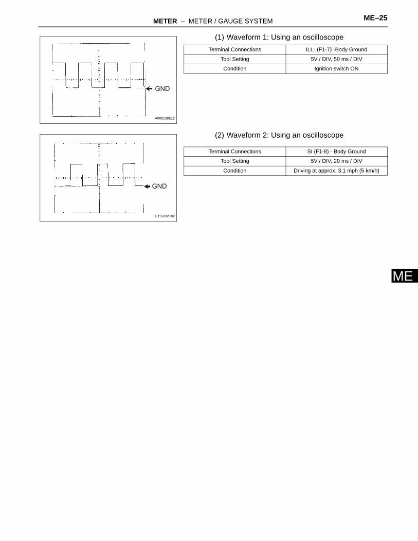
M(1) Waveform 1: Using an oscilloscope
(2) Waveform 2: Using an oscilloscope
GND
A005138E12
Terminal Connections ILL- (F1-7) -Body Ground
Tool Setting 5V / DIV, 50 ms / DIV
Condition Ignition switch ON
GND
E115032E02
Terminal Connections SI (F1-8) - Body Ground
Tool Setting 5V / DIV, 20 ms / DIV
Condition Driving at approx. 3.1 mph (5 km/h)
ME–26 METER – METER / GAUGE SYSTEM
ME
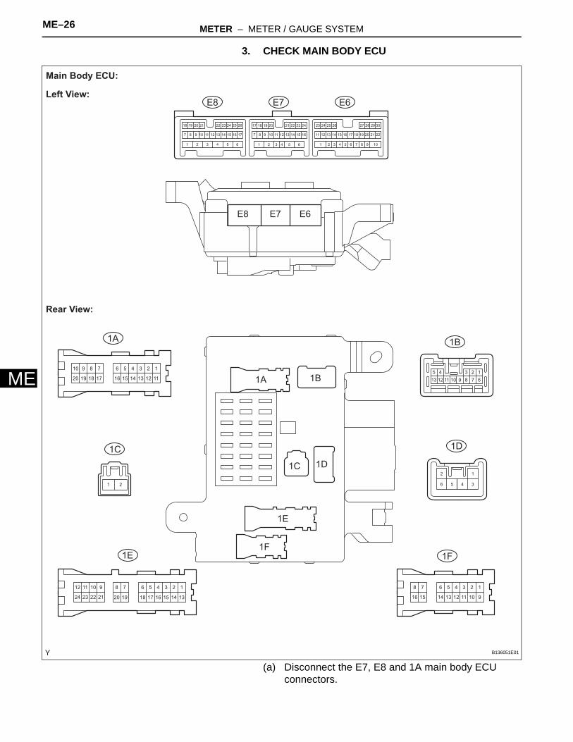
3. CHECK MAIN BODY ECU
(a) Disconnect the E7, E8 and 1A main body ECU connectors.
123456
111213141516
78910
17181920
123456
91011121314
78
1516
123456
1314
78
151617181920
910
2122
1112
2324
12345
678910111213
106 9565 844 733 622 511 4
16
3
15
2
14
1
13 2212
30291817 282726252423
2111 2010 199 181787171615141312111098 16151413
24
7
232221262524
1211
2023 1921201918 22
12
34561 2
E6
1A 1B
1D
1F1E
1C
E7E8
E6
1A 1B
1D
1F
1E
1C
E7E8
Main Body ECU:
Left View:
Rear View:
B136051E01
METER – METER / GAUGE SYSTEM ME–27
E
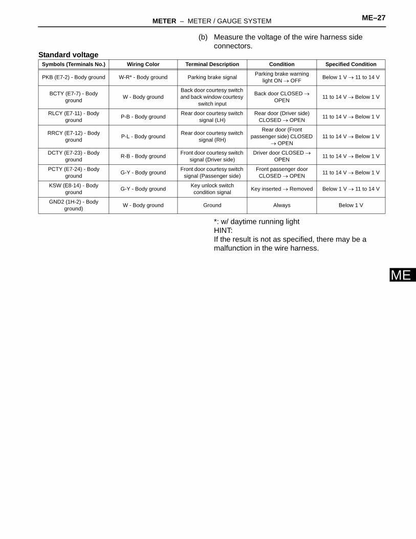
M(b) Measure the voltage of the wire harness side connectors.
Standard voltage
*: w/ daytime running lightHINT:If the result is not as specified, there may be a malfunction in the wire harness.
Symbols (Terminals No.) Wiring Color Terminal Description Condition Specified Condition
PKB (E7-2) - Body ground W-R* - Body ground Parking brake signal Parking brake warning light ON → OFF Below 1 V → 11 to 14 V
BCTY (E7-7) - Body ground W - Body ground
Back door courtesy switch and back window courtesy
switch input
Back door CLOSED → OPEN 11 to 14 V → Below 1 V
RLCY (E7-11) - Body ground P-B - Body ground Rear door courtesy switch
signal (LH)Rear door (Driver side)
CLOSED → OPEN 11 to 14 V → Below 1 V
RRCY (E7-12) - Body ground P-L - Body ground Rear door courtesy switch
signal (RH)
Rear door (Front passenger side) CLOSED
→ OPEN11 to 14 V → Below 1 V
DCTY (E7-23) - Body ground R-B - Body ground Front door courtesy switch
signal (Driver side)Driver door CLOSED →
OPEN 11 to 14 V → Below 1 V
PCTY (E7-24) - Body ground G-Y - Body ground Front door courtesy switch
signal (Passenger side)Front passenger door CLOSED → OPEN 11 to 14 V → Below 1 V
KSW (E8-14) - Body ground G-Y - Body ground Key unlock switch
condition signal Key inserted → Removed Below 1 V → 11 to 14 V
GND2 (1H-2) - Body ground) W - Body ground Ground Always Below 1 V
ME–28 METER – METER / GAUGE SYSTEM
ME
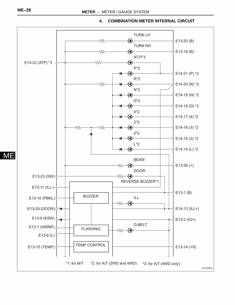
4. COMBINATION METER INTERNAL CIRCUIT
TURN LH
TURN RH
AT-P*3
P*2
R*2
N*2
D*2
4*2
3*2
2*2
L*2
BEAM
DOOR
REVERSE BUZZER*1
ILL
D-BELT
BUZZER
FLASHING
TEMP CONTROL
E13-20 (B)
E13-18 (B)
E14-21 (P) *2
E14-20 (R) *2
E14-19 (N) *2
E14-18 (D) *2
E14-17 (4) *2
E14-16 (3) *2
E14-15 (2) *2
E14-14 (L) *2
E13-26 (+)
E13-1 (B)
E14-13 (ILL+)
E13-2 (IG+)
E13-14 (+S)
E14-22 (ATP) *3
E13-23 (SW)
E13-11 (ILL-)
E13-10 (PBKL)
E13-29 (DOOR)
E13-9 (KSW)
E13-7 (WRNP)
E13-8 (L)
E13-15 (TEMP)
*1: for M/T *2: for A/T (2WD and 4WD) *3: for A/T (4WD only)E125399E01
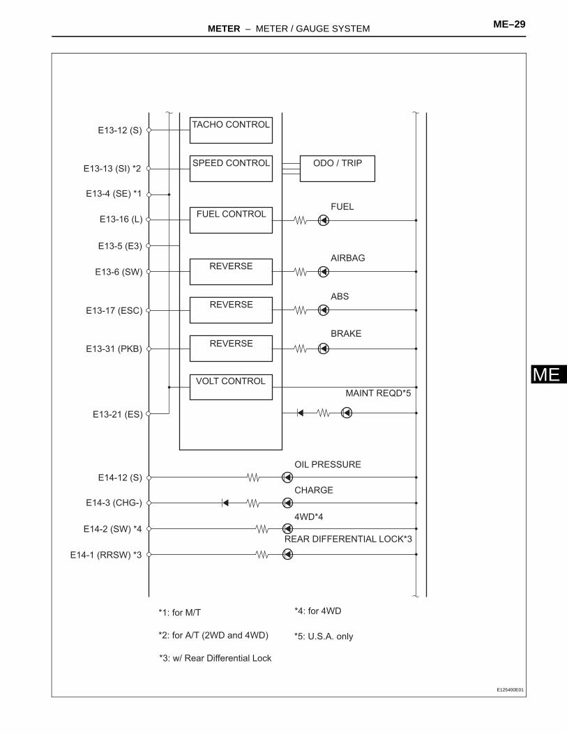
METER – METER / GAUGE SYSTEM ME–29
E
ME13-12 (S)
E13-13 (SI) *2
E13-4 (SE) *1
E13-16 (L)
E13-5 (E3)
E13-6 (SW)
E13-17 (ESC)
E13-31 (PKB)
E13-21 (ES)
E14-12 (S)
E14-3 (CHG-)
E14-2 (SW) *4
E14-1 (RRSW) *3
TACHO CONTROL
SPEED CONTROL
FUEL CONTROL
REVERSE
REVERSE
REVERSE
VOLT CONTROL
ODO / TRIP
FUEL
AIRBAG
ABS
BRAKE
MAINT REQD*5
OIL PRESSURE
CHARGE
4WD*4
REAR DIFFERENTIAL LOCK*3
*1: for M/T
*2: for A/T (2WD and 4WD)
*3: w/ Rear Differential Lock
*4: for 4WD
*5: U.S.A. only
E125400E01

ME–30 METER – METER / GAUGE SYSTEM
ME
E14-8 (CHK)
E14-11 (OILW) *2
E14-4 (A/D) *1
E14-10 (ALSD) *5
E14-7 (SLIP)
E14-6 (VSCW)
E14-5 (TROF) *4
E14-9 (ATRA) *3
CHECK ENGINE
A/T OIL TEMP*2
CRUISE*1
AUTO LSD*5
SLIP
VSC TRAC
VSC OFF*4
A-TRAC*3
*1: w/ Cruise Control
*2: for A/T (2WD and 4WD)
*3: w/ Active Traction Control (4WD only)
*4: w/ Rear Differential Lock
*5: for 2WD
E125401E01
METER – METER / GAUGE SYSTEM ME–31
E
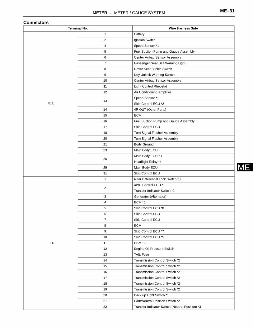
MConnectorsTerminal No. Wire Harness Side
E13
1 Battery
2 Ignition Switch
4 Speed Sensor *1
5 Fuel Suction Pump and Gauge Assembly
6 Center Airbag Sensor Assembly
7 Passenger Seat Belt Warning Light
8 Driver Seat Buckle Switch
9 Key Unlock Warning Switch
10 Center Airbag Sensor Assembly
11 Light Control Rheostat
12 Air Conditioning Amplifier
13Speed Sensor *1
Skid Control ECU *2
14 4P-OUT (Other Parts)
15 ECM
16 Fuel Suction Pump and Gauge Assembly
17 Skid Control ECU
18 Turn Signal Flasher Assembly
20 Turn Signal Flasher Assembly
21 Body Ground
23 Main Body ECU
26Main Body ECU *3
Headlight Relay *4
29 Main Body ECU
31 Skid Control ECU
E14
1 Rear Differential Lock Switch *8
24WD Control ECU *1
Transfer Indicator Switch *2
3 Generator (Alternator)
4 ECM *6
5 Skid Control ECU *8
6 Skid Control ECU
7 Skid Control ECU
8 ECM
9 Skid Control ECU *7
10 Skid Control ECU *5
11 ECM *2
12 Engine Oil Pressure Switch
13 TAIL Fuse
14 Transmission Control Switch *2
15 Transmission Control Switch *2
16 Transmission Control Switch *2
17 Transmission Control Switch *2
18 Transmission Control Switch *2
19 Transmission Control Switch *2
20 Back up Light Switch *1
21 Park/Neutral Position Switch *2
22 Transfer Indicator Switch (Neutral Position) *3
ME–32 METER – METER / GAUGE SYSTEM
ME
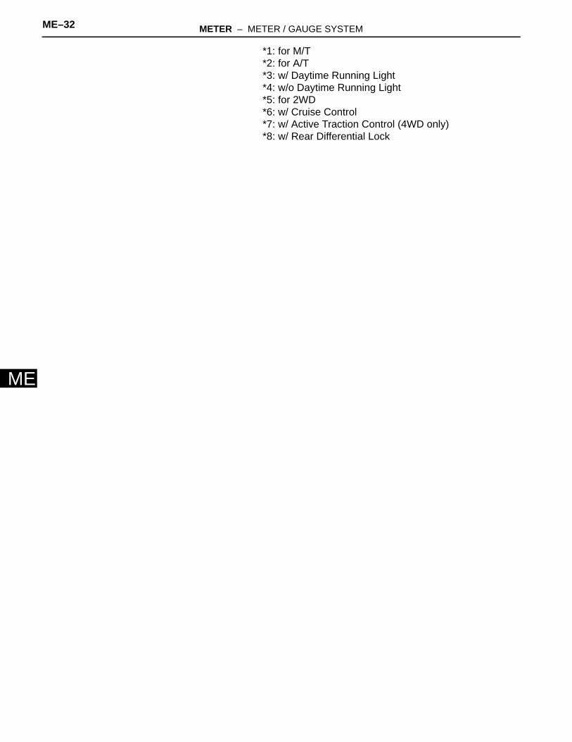
*1: for M/T*2: for A/T*3: w/ Daytime Running Light*4: w/o Daytime Running Light*5: for 2WD*6: w/ Cruise Control*7: w/ Active Traction Control (4WD only)*8: w/ Rear Differential Lock
METER – METER / GAUGE SYSTEM ME–33
E
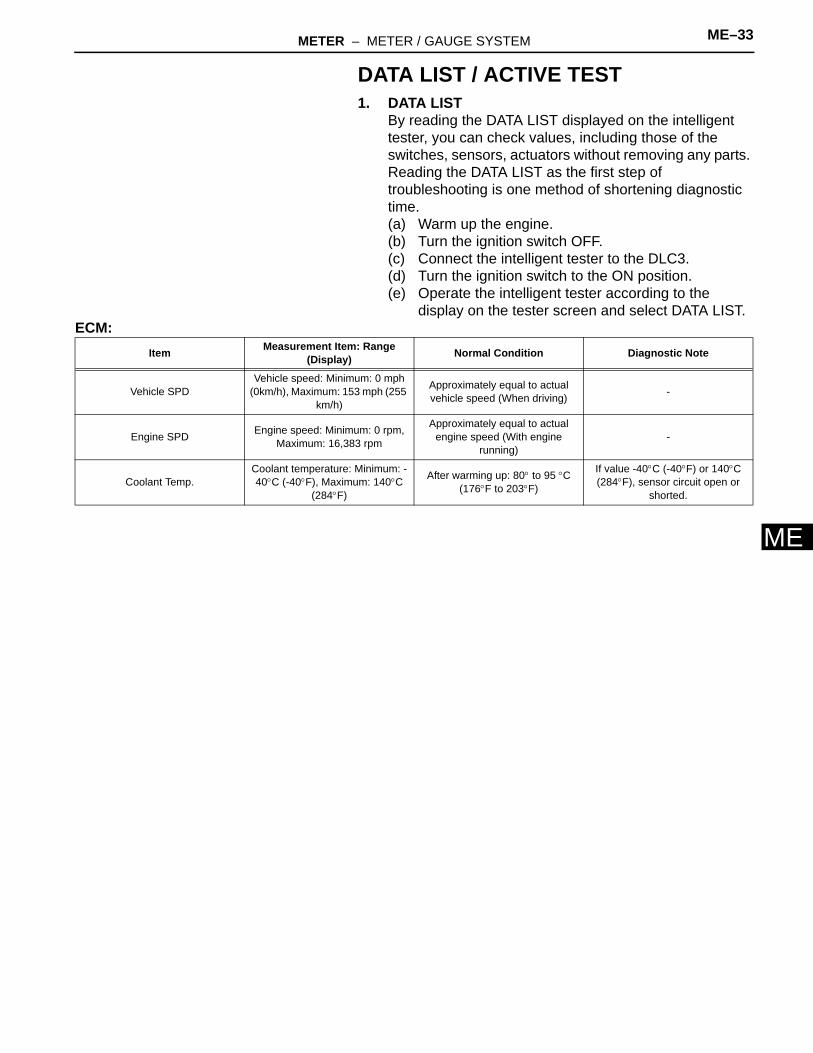
MDATA LIST / ACTIVE TEST1. DATA LIST
By reading the DATA LIST displayed on the intelligent tester, you can check values, including those of the switches, sensors, actuators without removing any parts. Reading the DATA LIST as the first step of troubleshooting is one method of shortening diagnostic time.(a) Warm up the engine.(b) Turn the ignition switch OFF.(c) Connect the intelligent tester to the DLC3.(d) Turn the ignition switch to the ON position.(e) Operate the intelligent tester according to the
display on the tester screen and select DATA LIST.ECM:
Item Measurement Item: Range (Display) Normal Condition Diagnostic Note
Vehicle SPDVehicle speed: Minimum: 0 mph
(0km/h), Maximum: 153 mph (255 km/h)
Approximately equal to actual vehicle speed (When driving) -
Engine SPD Engine speed: Minimum: 0 rpm, Maximum: 16,383 rpm
Approximately equal to actual engine speed (With engine
running)-
Coolant Temp.Coolant temperature: Minimum: -40°C (-40°F), Maximum: 140°C
(284°F)
After warming up: 80° to 95 °C (176°F to 203°F)
If value -40°C (-40°F) or 140°C (284°F), sensor circuit open or
shorted.

ME–34 METER – METER / GAUGE SYSTEM
ME
ON-VEHICLE INSPECTION1. INSPECT SPEEDOMETER
(a) Check the operation.(1) Using a speedometer tester, inspect the
speedometer and confirm that the speedometer readings are within the acceptable range. Also check the odometer operation.Reference:km/h (Canada)
mph (U.S.A.)
NOTICE:Tire wear and excessively high or low tire pressure affect speedometer indications.
(2) Check the deflection of the speedometer indicator.Reference:
Below 0.3 mph (0.5 km/h)
Standard Indication Acceptable Range
20 km/h 17.5 to 21.5 km/h
40 km/h 38 to 42 km/h
60 km/h 58 to 63 km/h
80 km/h 78 to 84 km/h
100 km/h 98.5 to 104.5 km/h
120 km/h 119 to 125 km/h
140 km/h 139 to 146 km/h
160 km/h 159 to 167 km/h
180 km/h 179 to 188 km/h
200 km/h 199 to 209 km/h
Standard Indication Acceptable Range
20 mph 19 to 22 mph
40 mph 39 to 42.5 mph
60 mph 59.5 to 63.5 mph
80 mph 79.5 to 84 mph
100 mph 100 to 105 mph
120 mph 121 to 126.5 mph

METER – METER / GAUGE SYSTEM ME–35
E
M2. INSPECT SPEED SENSOR(a) Check the output signal waveform.
(1) Remove the combination meter assembly, but do not disconnect the connector.
(2) Connect an oscilloscope to terminal E13-4 and to the body ground.
(3) Start the engine.(4) Check the signal waveform according to the
conditions in the table below.
OK:As shown in the illustration.
NOTICE:As the vehicle speed increases, the cycle of the signal waveform narrows.
(5) Reinstall the combination meter assembly.
3. INSPECT TACHOMETER(a) Check the operation.
(1) Connect the tune-up test tachometer and start the engine.NOTICE:• Reversing the connection of the
tachometer will damage the transistors and the insides of the diodes.
• When removing or installing the tachometer, be careful not to drop or strike it.
(2) Compare the result of the test with the standard indication.DC 13.5 V, at 25°C (77°F)Reference
GND
Waveform:
Combination Meter Assembly Connector:
E13
SE
E125403E01
Item Contents
Terminal Connection SE (E13-4) and Body Ground
Tool Setting 5V / DIV, 20ms / DIV
Condition Driving at approximately 12mph (20km / h)
Standard Indication (USA) (RPM)Standard Indication (CANADA) (r/
min)Data in ( ) are for reference
Acceptable Range (USA) (RPM)Acceptable Range (CANADA) (r/min)
Data in ( ) are for reference
700 630 to 770
1,000 (900 to 1,100)
2,000 (1,850 to 2,150)
3,000 2,800 to 3,200
4,000 (3,800 to 4,200)
5,000 4,800 to 5,100
(6,000) (5,750 to 6,250)

ME–36 METER – METER / GAUGE SYSTEM
ME
4. INSPECT FUEL RECEIVER GAUGE(a) Disconnect the L5 fuel sender gauge connector.(b) Check the fuel receiver gauge operation when the
ignition switch is turned to the ON position.OK:
Needle position is on EMPTY.(c) Connect terminals 2 and 3 on the wire harness side
connector of the fuel sender gauge.(d) Check the fuel receiver gauge operation when the
ignition switch is turned from OFF to ON.OK:
Needle position is on FULL.(e) Reconnect the fuel sender gauge connector.
5. INSPECT FUEL LEVEL WARNING LIGHT(a) Disconnect the fuel sender gauge connector.(b) Turn the ignition switch to the ON position, then
check that the fuel level needle indicates EMPTY and the fuel level warning light comes on.OK:
Fuel level warning light comes on.(c) Reconnect the fuel sender gauge connector.
6. INSPECT ENGINE OIL PRESSURE WARNING LIGHT(a) Disconnect the engine oil pressure switch
connector.(b) Turn the ignition switch to the ON position.(c) Ground the terminal of the wire harness side
connector, then check the engine oil pressure warning light.OK:
Engine oil pressure warning light illuminates.(d) Reconnect the engine oil pressure switch connector.
7. INSPECT BRAKE WARNING LIGHT(a) Inspect the parking brake warning light.
(1) Disconnect the parking brake switch connector.(2) Turn the ignition switch to the ON position.(3) Ground the terminal of the wire harness side
connector, then check the parking brake warning light.OK:
Brake warning light illuminates.(4) Reconnect the parking brake switch connector.
(b) Inspect the brake fluid level warning light.(1) Disconnect the brake fluid level warning switch
connector.(2) Turn the ignition switch to the ON position.(3) Connect a terminal to the other terminal of the
wire harness side connector, then check the brake fluid level warning switch.OK:
Brake warning light illuminates.(4) Reconnect the brake fluid level warning switch
connector.
Wire Harness Side:
Front View
Fuel Sender Gauge Connector
L5
E126857E01
METER – METER / GAUGE SYSTEM ME–37
E
M8. INSPECT BRAKE FLUID LEVEL WARNING SWITCH(a) Remove the reservoir tank cap and strainer.(b) Disconnect the brake fluid level warning switch
connector.(c) Measure the resistance between the terminals.
Standard resistance:Float inside reservoir tank is in high position (switch OFF): 10 k Ω or higher
(d) Use a syphon or a similar tool to drain fluid out of the reservoir tank.
(e) Measure the resistance between the terminals.Standard resistance:
Float inside reservoir tank is in low position (switch ON): Below 1 Ω
(f) Pour the fluid back into the reservoir tank.(g) Reconnect the brake fluid level warning switch
connector.(h) Reinstall the reservoir tank cap and strainer.
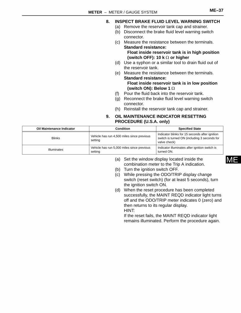
9. OIL MAINTENANCE INDICATOR RESETTING PROCEDURE (U.S.A. only)
(a) Set the window display located inside the combination meter to the Trip A indication.
(b) Turn the ignition switch OFF.(c) While pressing the ODO/TRIP display change
switch (reset switch) (for at least 5 seconds), turn the ignition switch ON.
(d) When the reset procedure has been completed successfully, the MAINT REQD indicator light turns off and the ODO/TRIP meter indicates 0 (zero) and then returns to its regular display.HINT:If the reset fails, the MAINT REQD indicator light remains illuminated. Perform the procedure again.
Oil Maintenance Indicator Condition Specified State
Blinks Vehicle has run 4,500 miles since previous setting
Indicator blinks for 15 seconds after ignition switch is turned ON (including 3 seconds for valve check)
Illuminates Vehicle has run 5,000 miles since previous setting
Indicator illuminates after ignition switch is turned ON.
ME–38 METER – METER / GAUGE SYSTEM
ME
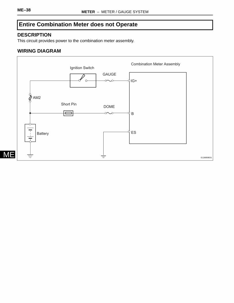
DESCRIPTIONThis circuit provides power to the combination meter assembly.
WIRING DIAGRAM
Entire Combination Meter does not Operate
ES
B
IG+
Combination Meter Assembly
GAUGE
Ignition Switch
AM2
Battery
DOMEShort Pin
E126859E01
METER – METER / GAUGE SYSTEM ME–39
E
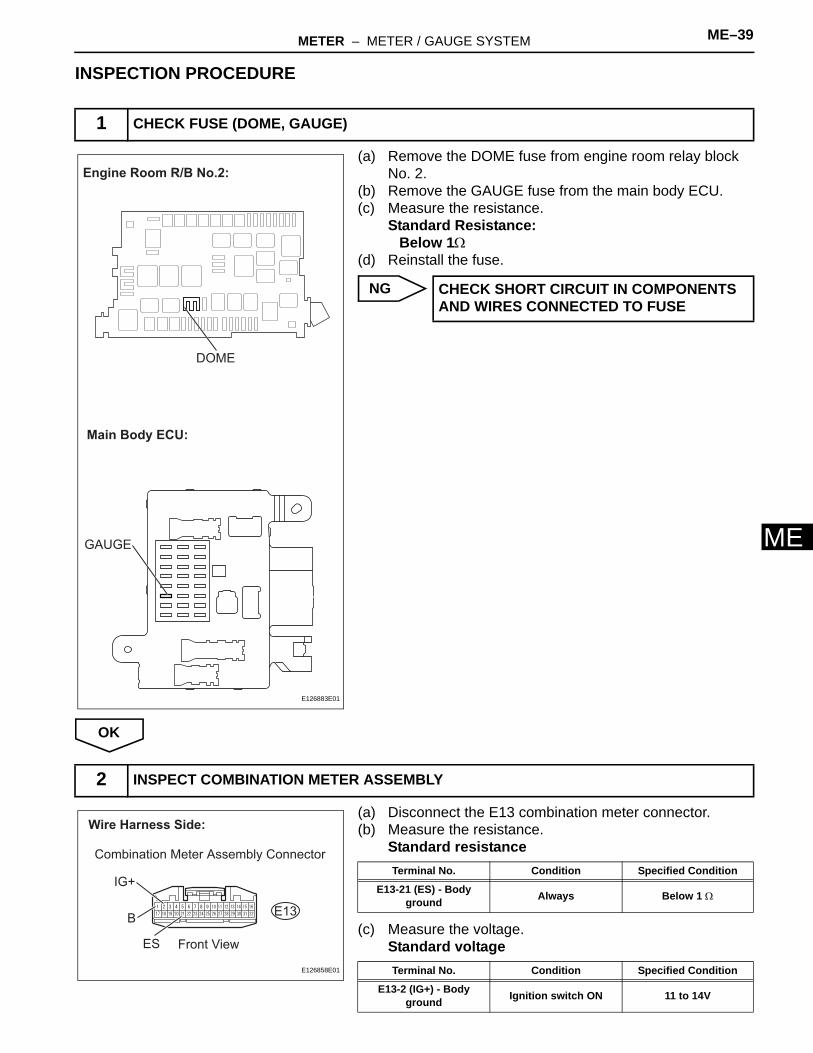
MINSPECTION PROCEDURE
(a) Remove the DOME fuse from engine room relay block No. 2.
(b) Remove the GAUGE fuse from the main body ECU.(c) Measure the resistance.
Standard Resistance:Below 1Ω
(d) Reinstall the fuse.
NG
OK
(a) Disconnect the E13 combination meter connector.(b) Measure the resistance.
Standard resistance
(c) Measure the voltage.Standard voltage
1 CHECK FUSE (DOME, GAUGE)
Engine Room R/B No.2:
DOME
GAUGE
Main Body ECU:
E126883E01
CHECK SHORT CIRCUIT IN COMPONENTS AND WIRES CONNECTED TO FUSE
2 INSPECT COMBINATION METER ASSEMBLY
Wire Harness Side:
E13
Combination Meter Assembly Connector
Front ViewES
IG+
B
E126858E01
Terminal No. Condition Specified Condition
E13-21 (ES) - Body ground Always Below 1 Ω
Terminal No. Condition Specified Condition
E13-2 (IG+) - Body ground Ignition switch ON 11 to 14V
ME–40 METER – METER / GAUGE SYSTEM
ME
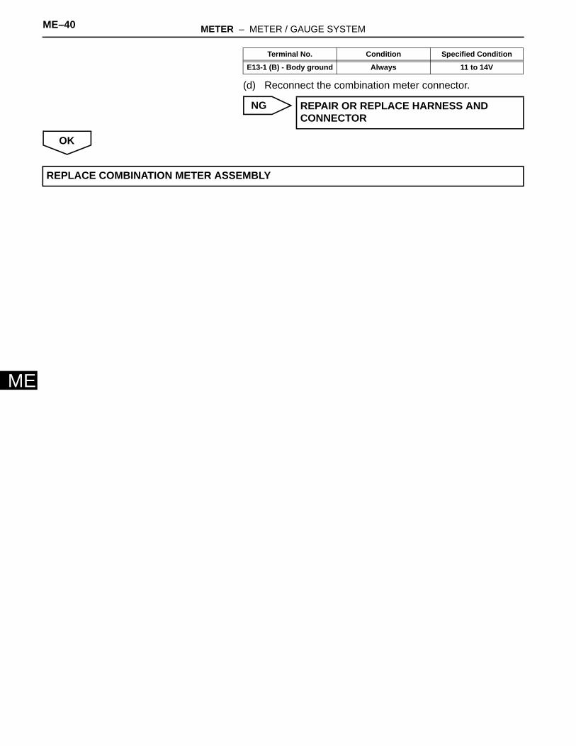
(d) Reconnect the combination meter connector.
NG
OK
E13-1 (B) - Body ground Always 11 to 14V
REPAIR OR REPLACE HARNESS AND CONNECTOR
Terminal No. Condition Specified Condition
REPLACE COMBINATION METER ASSEMBLY
METER – METER / GAUGE SYSTEM ME–41
E
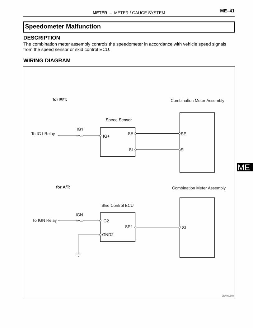
MDESCRIPTIONThe combination meter assembly controls the speedometer in accordance with vehicle speed signals from the speed sensor or skid control ECU.
WIRING DIAGRAM
Speedometer Malfunction
for M/T:
for A/T:
Combination Meter Assembly
Combination Meter Assembly
Speed Sensor
Skid Control ECU
IG1
IGN
To IG1 Relay
To IGN Relay
IG+SE
SI
SE
SI
SISP1
IG2
GND2
E126860E02
ME–42 METER – METER / GAUGE SYSTEM
ME
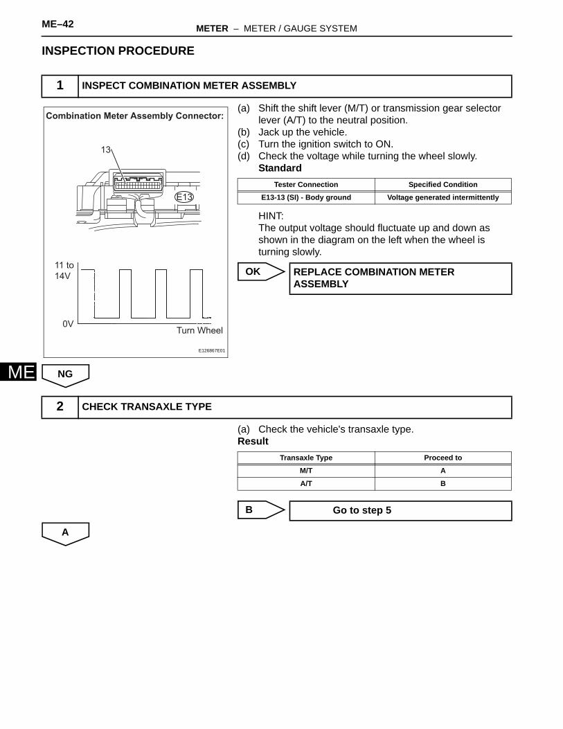
INSPECTION PROCEDURE
(a) Shift the shift lever (M/T) or transmission gear selector lever (A/T) to the neutral position.
(b) Jack up the vehicle.(c) Turn the ignition switch to ON.(d) Check the voltage while turning the wheel slowly.
Standard
HINT:The output voltage should fluctuate up and down as shown in the diagram on the left when the wheel is turning slowly.
OK
NG
(a) Check the vehicle's transaxle type.Result
B
A
1 INSPECT COMBINATION METER ASSEMBLY
11 to
14V
0VTurn Wheel
Combination Meter Assembly Connector:
E13
13
E126867E01
Tester Connection Specified Condition
E13-13 (SI) - Body ground Voltage generated intermittently
REPLACE COMBINATION METER ASSEMBLY
2 CHECK TRANSAXLE TYPE
Transaxle Type Proceed to
M/T A
A/T B
Go to step 5
METER – METER / GAUGE SYSTEM ME–43
E
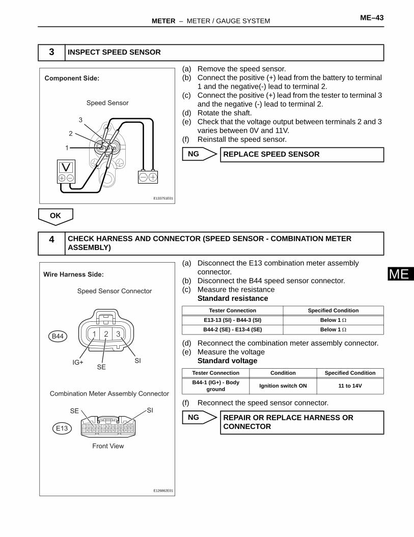
M(a) Remove the speed sensor.(b) Connect the positive (+) lead from the battery to terminal
1 and the negative(-) lead to terminal 2.(c) Connect the positive (+) lead from the tester to terminal 3
and the negative (-) lead to terminal 2.(d) Rotate the shaft.(e) Check that the voltage output between terminals 2 and 3
varies between 0V and 11V.(f) Reinstall the speed sensor.
NG
OK
(a) Disconnect the E13 combination meter assembly connector.
(b) Disconnect the B44 speed sensor connector.(c) Measure the resistance
Standard resistance
(d) Reconnect the combination meter assembly connector.(e) Measure the voltage
Standard voltage
(f) Reconnect the speed sensor connector.
NG
3 INSPECT SPEED SENSOR
Component Side:
Speed Sensor
1
2
3
E133751E01
REPLACE SPEED SENSOR
4 CHECK HARNESS AND CONNECTOR (SPEED SENSOR - COMBINATION METER ASSEMBLY)
Wire Harness Side:
Speed Sensor Connector
Combination Meter Assembly Connector
B44
SIIG+
SI
SE
E13
Front View
SE
E126862E01
Tester Connection Specified Condition
E13-13 (SI) - B44-3 (SI) Below 1 Ω
B44-2 (SE) - E13-4 (SE) Below 1 Ω
Tester Connection Condition Specified Condition
B44-1 (IG+) - Body ground Ignition switch ON 11 to 14V
REPAIR OR REPLACE HARNESS OR CONNECTOR
ME–44 METER – METER / GAUGE SYSTEM
ME
OK
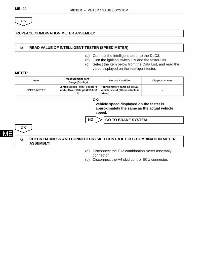
(a) Connect the intelligent tester to the DLC3.(b) Turn the ignition switch ON and the tester ON.(c) Select the item below from the Data List, and read the
value displayed on the intelligent tester.METER
OK:Vehicle speed displayed on the tester is approximately the same as the actual vehicle speed.
NG
OK
(a) Disconnect the E13 combination meter assembly connector.
(b) Disconnect the A4 skid control ECU connector.
REPLACE COMBINATION METER ASSEMBLY
5 READ VALUE OF INTELLIGENT TESTER (SPEED METER)
Item Measurement Item / Range(Display) Normal Condition Diagnostic Note
SPEED METERVehicle speed / Min.: 0 mph (0 km/h), Max.: 158mph (255 km/
h)
Approximately same as actual vehicle speed (When vehicle is driven)
-
GO TO BRAKE SYSTEM
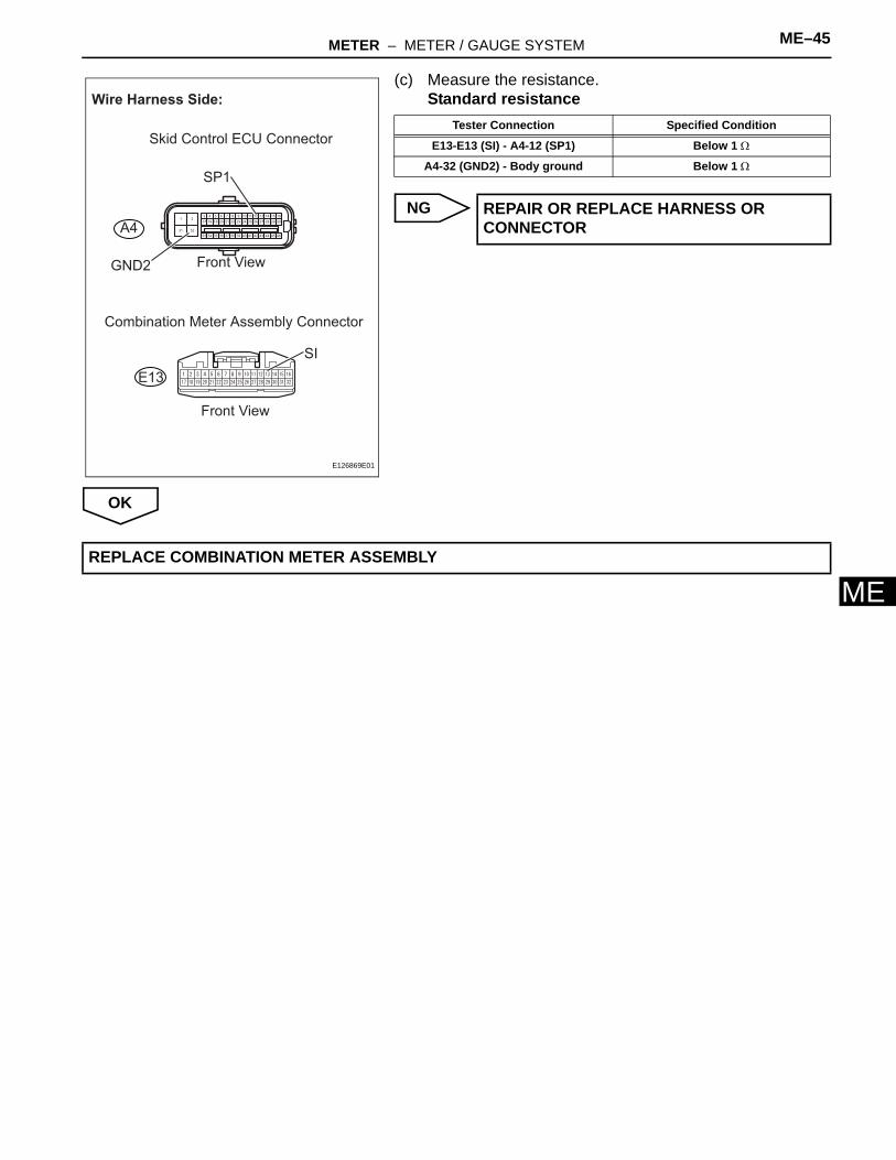
6 CHECK HARNESS AND CONNECTOR (SKID CONTROL ECU - COMBINATION METER ASSEMBLY)
METER – METER / GAUGE SYSTEM ME–45
E
M(c) Measure the resistance.Standard resistance
NG
OK
31 32
213 4 5 6 7 8 9 10 11 12 13 14 15 16
17 18 19 20 21 22 23 24 25 26 27 28 29 30
33 34 35 36 37 38 39 40 41 42 43 44 45 46
Wire Harness Side:
SP1
GND2
A4
Skid Control ECU Connector
Front View
Combination Meter Assembly Connector
E13
SI
Front View
E126869E01
Tester Connection Specified Condition
E13-E13 (SI) - A4-12 (SP1) Below 1 Ω
A4-32 (GND2) - Body ground Below 1 Ω
REPAIR OR REPLACE HARNESS OR CONNECTOR
REPLACE COMBINATION METER ASSEMBLY
ME–46 METER – METER / GAUGE SYSTEM
ME
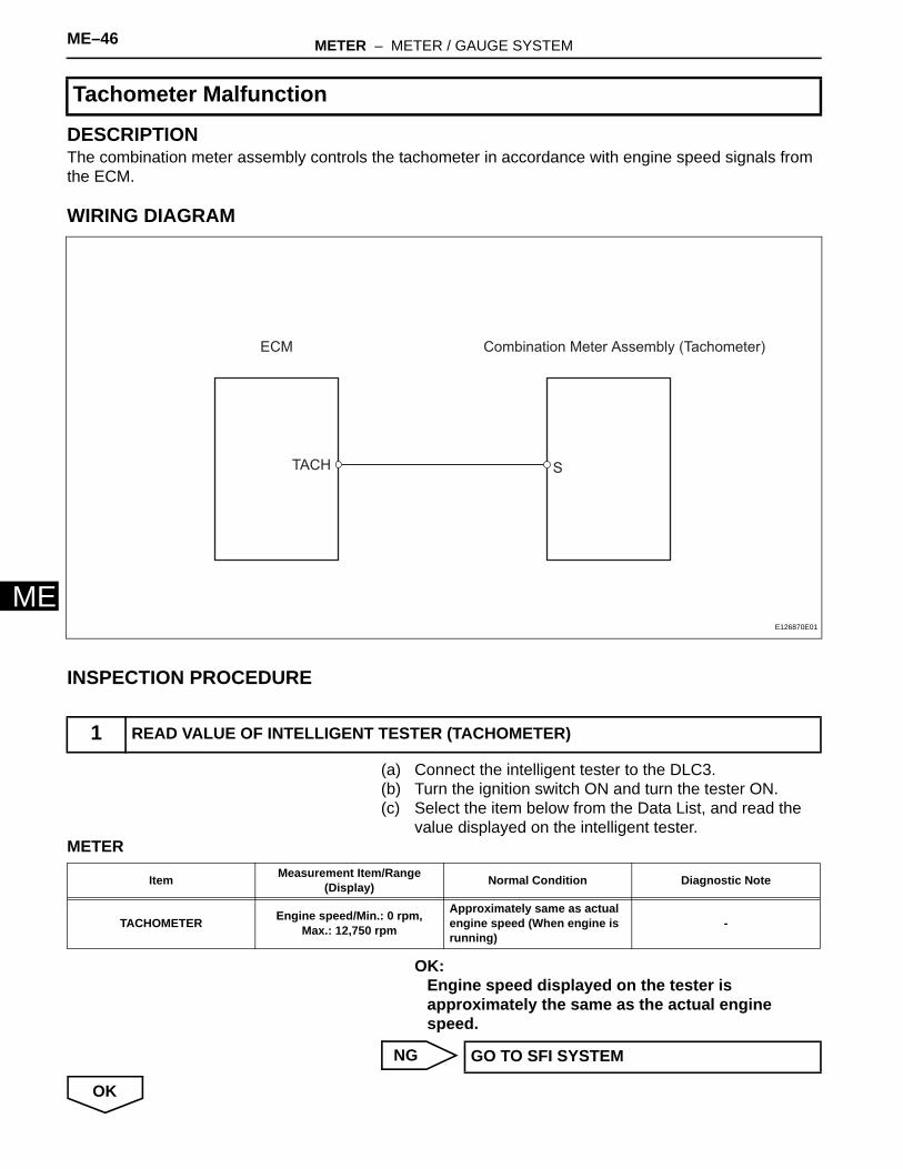
DESCRIPTIONThe combination meter assembly controls the tachometer in accordance with engine speed signals from the ECM.
WIRING DIAGRAM
INSPECTION PROCEDURE
(a) Connect the intelligent tester to the DLC3.(b) Turn the ignition switch ON and turn the tester ON.(c) Select the item below from the Data List, and read the
value displayed on the intelligent tester.METER
OK:Engine speed displayed on the tester is approximately the same as the actual engine speed.
NG
OK
Tachometer Malfunction
1 READ VALUE OF INTELLIGENT TESTER (TACHOMETER)
Combination Meter Assembly (Tachometer)ECM
STACH
E126870E01
Item Measurement Item/Range(Display) Normal Condition Diagnostic Note
TACHOMETER Engine speed/Min.: 0 rpm, Max.: 12,750 rpm
Approximately same as actual engine speed (When engine is running)
-
GO TO SFI SYSTEM
METER – METER / GAUGE SYSTEM ME–47
E
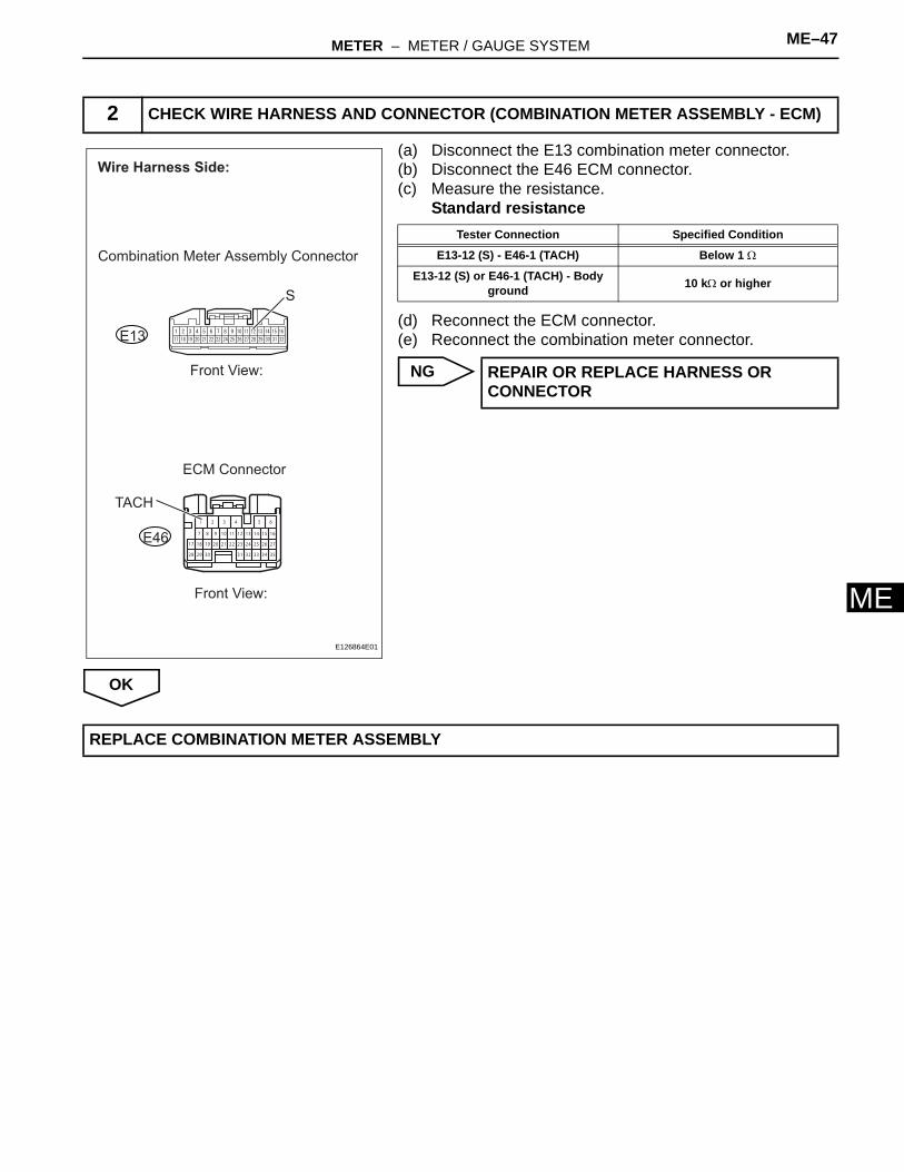
M(a) Disconnect the E13 combination meter connector.(b) Disconnect the E46 ECM connector.(c) Measure the resistance.
Standard resistance
(d) Reconnect the ECM connector.(e) Reconnect the combination meter connector.
NG
OK
2 CHECK WIRE HARNESS AND CONNECTOR (COMBINATION METER ASSEMBLY - ECM)
16
3231 3528
2017
9 10
34
11
65
13 14 15
23 24 26
12
321 4
27
29
18
7
30
19
8
21 22 25
33
Wire Harness Side:
Front View:
E13
S
Front View:
Combination Meter Assembly Connector
ECM Connector
TACH
E46
E126864E01
Tester Connection Specified Condition
E13-12 (S) - E46-1 (TACH) Below 1 Ω
E13-12 (S) or E46-1 (TACH) - Body ground 10 kΩ or higher
REPAIR OR REPLACE HARNESS OR CONNECTOR
REPLACE COMBINATION METER ASSEMBLY
ME–48 METER – METER / GAUGE SYSTEM
ME
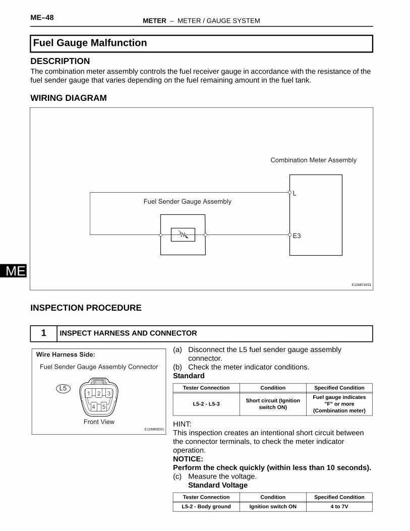
DESCRIPTIONThe combination meter assembly controls the fuel receiver gauge in accordance with the resistance of the fuel sender gauge that varies depending on the fuel remaining amount in the fuel tank.
WIRING DIAGRAM
INSPECTION PROCEDURE
(a) Disconnect the L5 fuel sender gauge assembly connector.
(b) Check the meter indicator conditions.Standard
HINT:This inspection creates an intentional short circuit between the connector terminals, to check the meter indicator operation.NOTICE:Perform the check quickly (within less than 10 seconds).(c) Measure the voltage.
Standard Voltage
Fuel Gauge Malfunction
1 INSPECT HARNESS AND CONNECTOR
Combination Meter Assembly
Fuel Sender Gauge Assembly
L
E3
E126871E01
Wire Harness Side:
Front View
L5
Fuel Sender Gauge Assembly Connector
E126865E01
Tester Connection Condition Specified Condition
L5-2 - L5-3 Short circuit (Ignition switch ON)
Fuel gauge indicates "F" or more
(Combination meter)
Tester Connection Condition Specified Condition
L5-2 - Body ground Ignition switch ON 4 to 7V
METER – METER / GAUGE SYSTEM ME–49
E
M(d) Reconnect the fuel sender gauge assembly connector.
NG
OK
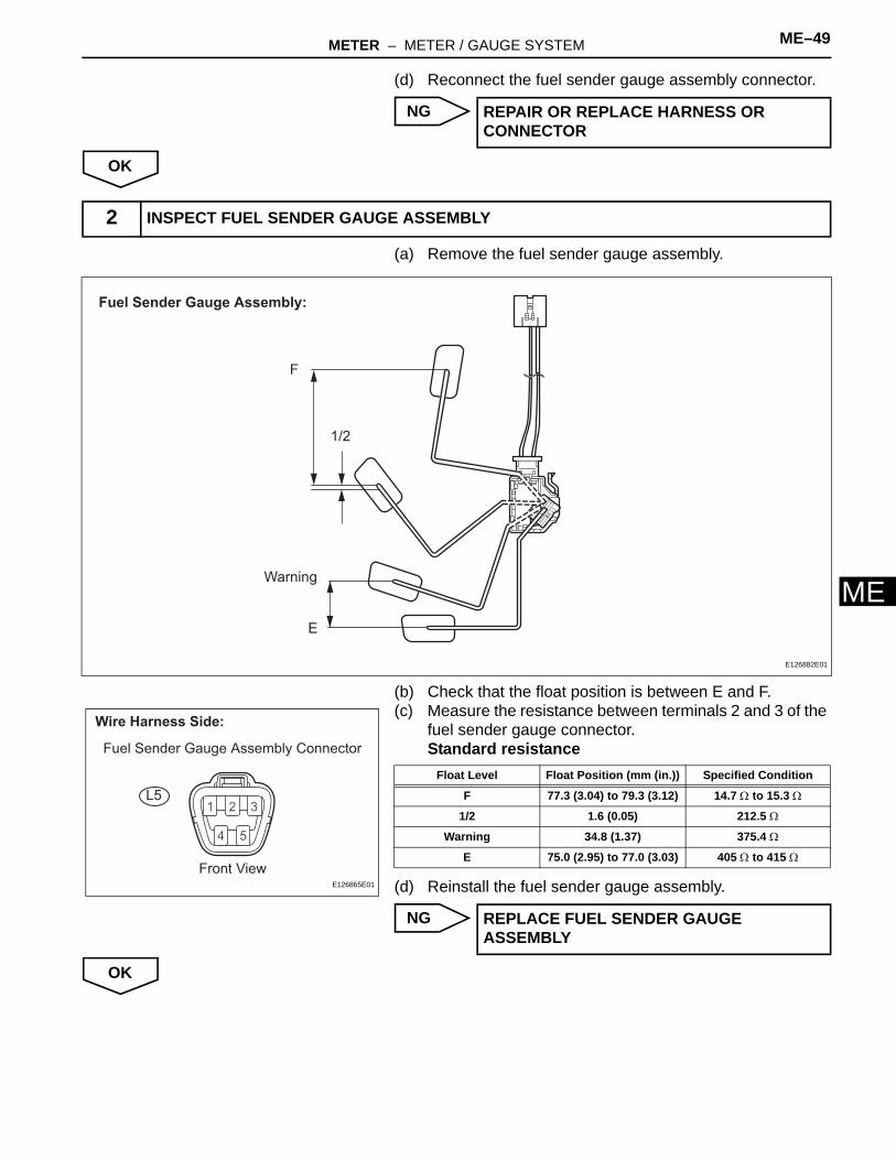
(a) Remove the fuel sender gauge assembly.
(b) Check that the float position is between E and F.(c) Measure the resistance between terminals 2 and 3 of the
fuel sender gauge connector.Standard resistance
(d) Reinstall the fuel sender gauge assembly.
NG
OK
REPAIR OR REPLACE HARNESS OR CONNECTOR
2 INSPECT FUEL SENDER GAUGE ASSEMBLY
F
E
Warning
1/2
Fuel Sender Gauge Assembly:
E126882E01
Wire Harness Side:
Front View
L5
Fuel Sender Gauge Assembly Connector
E126865E01
Float Level Float Position (mm (in.)) Specified Condition
F 77.3 (3.04) to 79.3 (3.12) 14.7 Ω to 15.3 Ω
1/2 1.6 (0.05) 212.5 Ω
Warning 34.8 (1.37) 375.4 Ω
E 75.0 (2.95) to 77.0 (3.03) 405 Ω to 415 Ω
REPLACE FUEL SENDER GAUGE ASSEMBLY
ME–50 METER – METER / GAUGE SYSTEM
ME
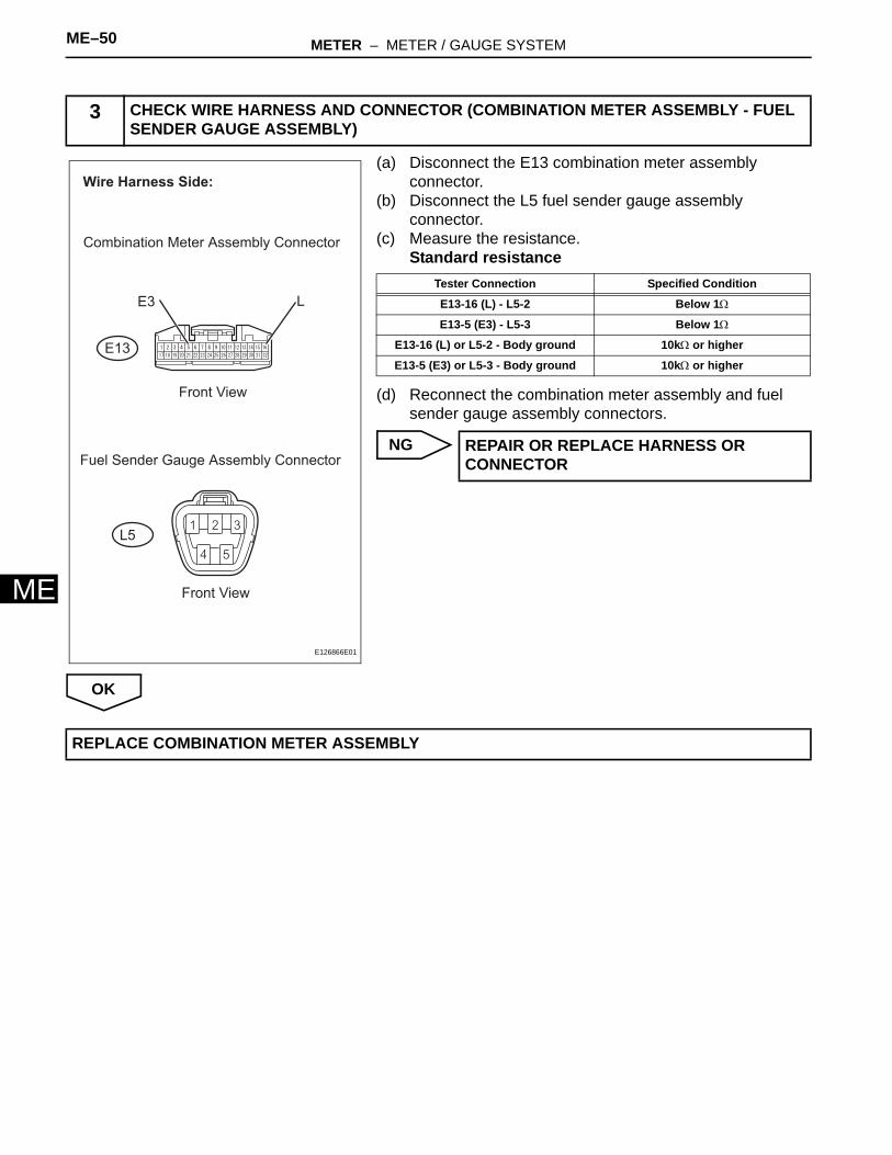
(a) Disconnect the E13 combination meter assembly connector.
(b) Disconnect the L5 fuel sender gauge assembly connector.
(c) Measure the resistance.Standard resistance
(d) Reconnect the combination meter assembly and fuel sender gauge assembly connectors.
NG
OK
3 CHECK WIRE HARNESS AND CONNECTOR (COMBINATION METER ASSEMBLY - FUEL SENDER GAUGE ASSEMBLY)
L
Wire Harness Side:
Combination Meter Assembly Connector
Fuel Sender Gauge Assembly Connector
E13
L5
Front View
E3
Front View
E126866E01
Tester Connection Specified Condition
E13-16 (L) - L5-2 Below 1Ω
E13-5 (E3) - L5-3 Below 1Ω
E13-16 (L) or L5-2 - Body ground 10kΩ or higher
E13-5 (E3) or L5-3 - Body ground 10kΩ or higher
REPAIR OR REPLACE HARNESS OR CONNECTOR
REPLACE COMBINATION METER ASSEMBLY

METER – METER / GAUGE SYSTEM ME–51
E
MDESCRIPTIONThe combination meter assembly controls the engine coolant temperature gauge in accordance with engine coolant temperature signals from the ECM.
WIRING DIAGRAM
INSPECTION PROCEDURE
(a) Connect the intelligent tester to the DLC3.(b) Turn the ignition switch ON and turn the tester ON.(c) Select the item below from the Data List, and read the
value displayed on the intelligent tester.METER
HINT:• If the value is 0°C (32°F), the sensor circuit is open.• If the value is 127.5°C (262°F), the sensor circuit is
shorted.OK:
Coolant temperature displayed on the tester is between 75°C (167°F) and 105°C (221°F) after warming up.
Malfunction in Water Temperature Warning Light
1 READ VALUE OF INTELLIGENT TESTER (ENGINE COOLANT TEMPERATURE)
Combination Meter AssemblyECM
THWO
E2
THW
TEMP
Engine Coolant
Temperature Sensor
E126874E01
Item Measurement Item/Range(Display) Normal Condition Diagnostic Note
COOLANT TEMP Engine coolant temperature / Min.: 0°C,Max.: 127.5°C
After warming up: 75 to 105°C (167 to 221°F) -
ME–52 METER – METER / GAUGE SYSTEM
ME
NG
OK
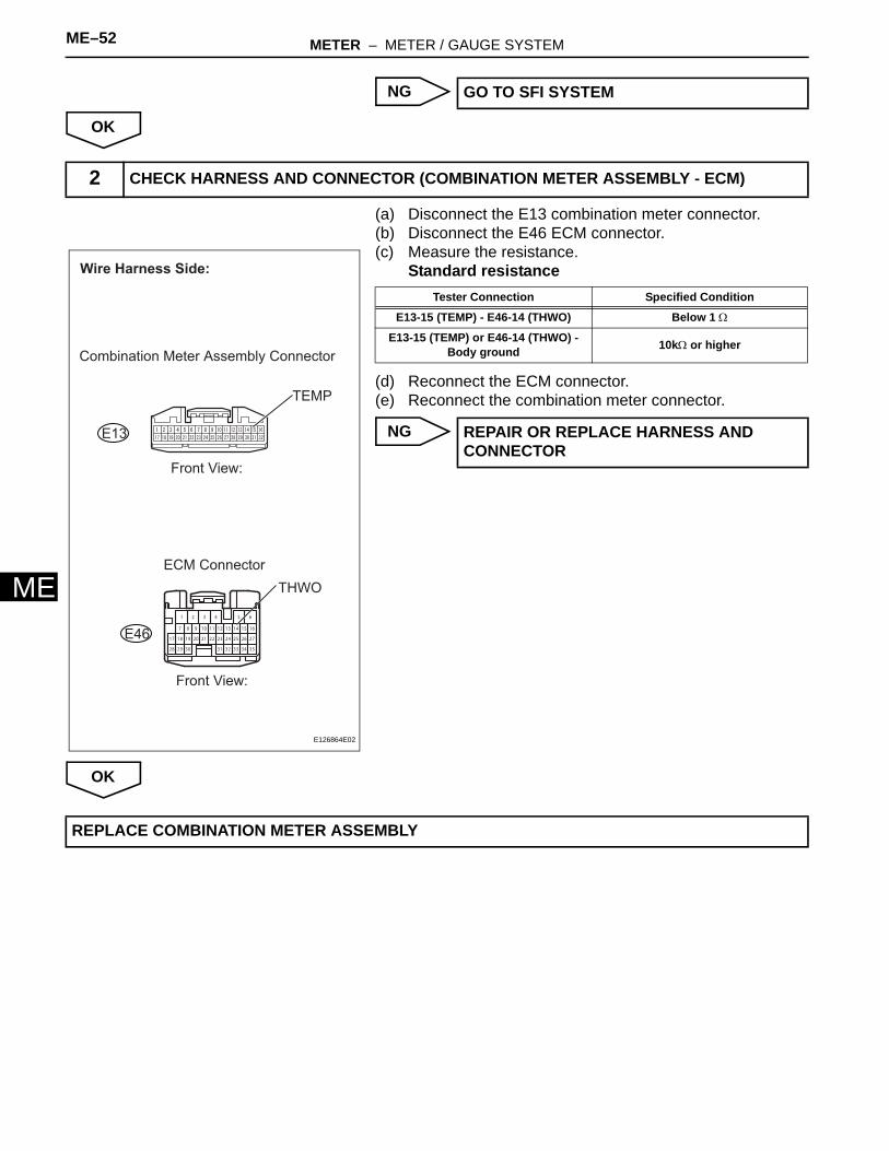
(a) Disconnect the E13 combination meter connector.(b) Disconnect the E46 ECM connector.(c) Measure the resistance.
Standard resistance
(d) Reconnect the ECM connector.(e) Reconnect the combination meter connector.
NG
OK
GO TO SFI SYSTEM
2 CHECK HARNESS AND CONNECTOR (COMBINATION METER ASSEMBLY - ECM)
16
3231 3528
2017
9 10
34
11
65
13 14 15
23 24 26
12
321 4
27
29
18
7
30
19
8
21 22 25
33
Wire Harness Side:
Front View:
E13
TEMP
Front View:
Combination Meter Assembly Connector
ECM Connector
E46
THWO
E126864E02
Tester Connection Specified Condition
E13-15 (TEMP) - E46-14 (THWO) Below 1 Ω
E13-15 (TEMP) or E46-14 (THWO) - Body ground 10kΩ or higher
REPAIR OR REPLACE HARNESS AND CONNECTOR
REPLACE COMBINATION METER ASSEMBLY

METER – METER / GAUGE SYSTEM ME–53
E
MDESCRIPTIONThe combination meter assembly controls the buzzers in accordance with signals from the front seat inner belt assembly LH, center airbag sensor assembly and the main body ECU.
WIRING DIAGRAM
INSPECTION PROCEDURE
(a) Check that the seat belt and key reminder buzzers sound.
Warning Buzzer does not Sound
1 CHECK BUZZER (SEAT BELT, KEY REMINDER)
Front Seat Inner
Belt Assembly RH
Front Seat Inner Belt Assembly LH
Occupant Classification ECU
Combination Meter
Assembly
ES
Main Body ECU
Front Door Courtesy Switch LH
Unlock Warning Switch Assembly
Center Airbag Sensor Assembly
L
To Front Seat Outer Belt
(Driver Side)RDC
+
E
PBKLPBEW
FSP-
FSP+FSR+
FSR-
BSW
BGND
RBE+
RBE-
KSW
DCTY
DCY2
KSWO
DOOR
KSW
E126876E01

ME–54 METER – METER / GAUGE SYSTEM
ME
Result
HINT:• Seat belt warning buzzer on: Ignition switch is ON,
driver or front passenger seat belt is unfastened, and vehicle speed is 12.4mph (20 km/h) or more.
• Key reminder warning buzzer on: Ignition switch is OFF, key is in ignition key cylinder, and driver side door is open.
B
C
D
A
(a) Disconnect the L19 front seat inner belt assembly (driver side) connector.
(b) Measure the resistance.Standard resistance
(c) Reconnect the front seat inner belt assembly (driver side) connector.
NG
OK
(a) Disconnect the E13 combination meter assembly connector.
(b) Disconnect the L19 front seat inner belt assembly (driver side) connector.
Result Proceed to
Seat belt warning buzzer does not sound (Driver side) A
Seat belt warning buzzer does not sound (Passenger side) B
Key reminder warning buzzer does not sound C
No warning buzzers sound D
Go to step 5
GO TO KEY REMINDER WARNING SYSTEM
REPLACE COMBINATION METER ASSEMBLY
2 INSPECT FRONT SEAT INNER BELT ASSEMBLY (DRIVER SIDE)
Component Side:
Front Seat Inner Belt Assembly
(Driver Side) Connector
+
ERDC
B137709E02
Tester Connection Condition Specified Condition
+ - E Tongue plate fastened 10 k Ω or higher
+ - E Tongue plate unfastened Below 1 Ω
REPLACE FRONT SEAT INNER BELT ASSEMBLY LH
3 CHECK HARNESS AND CONNECTOR (COMBINATION METER ASSEMBLY - FRONT SEAT INNER BELT ASSEMBLY)
METER – METER / GAUGE SYSTEM ME–55
E
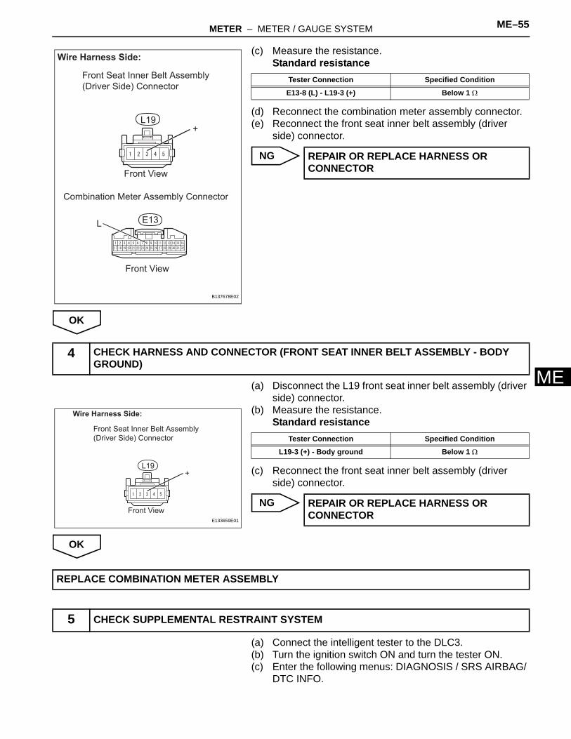
M(c) Measure the resistance.Standard resistance
(d) Reconnect the combination meter assembly connector.(e) Reconnect the front seat inner belt assembly (driver
side) connector.
NG
OK
(a) Disconnect the L19 front seat inner belt assembly (driver side) connector.
(b) Measure the resistance.Standard resistance
(c) Reconnect the front seat inner belt assembly (driver side) connector.
NG
OK
(a) Connect the intelligent tester to the DLC3.(b) Turn the ignition switch ON and turn the tester ON.(c) Enter the following menus: DIAGNOSIS / SRS AIRBAG/
DTC INFO.
Wire Harness Side:
Front Seat Inner Belt Assembly
(Driver Side) Connector
Combination Meter Assembly Connector
Front View
Front View
E13
L19+
L
B137678E02
Tester Connection Specified Condition
E13-8 (L) - L19-3 (+) Below 1 Ω
REPAIR OR REPLACE HARNESS OR CONNECTOR
4 CHECK HARNESS AND CONNECTOR (FRONT SEAT INNER BELT ASSEMBLY - BODY GROUND)
Wire Harness Side:
Front Seat Inner Belt Assembly
(Driver Side) Connector
Front View
L19+
E133659E01
Tester Connection Specified Condition
L19-3 (+) - Body ground Below 1 Ω
REPAIR OR REPLACE HARNESS OR CONNECTOR
REPLACE COMBINATION METER ASSEMBLY
5 CHECK SUPPLEMENTAL RESTRAINT SYSTEM

ME–56 METER – METER / GAUGE SYSTEM
ME
Result
B
A
(a) Connect the intelligent tester to the DLC3.(b) Turn the ignition switch ON and turn the tester ON.(c) Enter the following menus: DIAGNOSIS / OCCUPANT
DETECT /DTC INFO.Result
B
A
(a) Disconnect the E29 center airbag sensor assembly connector.
(b) Disconnect the E13 combination meter assembly connector.
Result Proceed to
No SRS DTCs are output A
SRS DTCs are output B
GO TO SUPPLEMENTAL RESTRAINT SYSTEM
6 CHECK OCCUPANT CLASSIFICATION SYSTEM
Result Proceed to
No occupant classification system DTCs are output A
Occupant classification system DTCs are output B
GO TO OCCUPANT CLASSIFICATION SYSTEM
7 CHECK HARNESS AND CONNECTOR (CENTER AIRBAG SENSOR ASSEMBLY - COMBINATION METER ASSEMBLY)
METER – METER / GAUGE SYSTEM ME–57
E
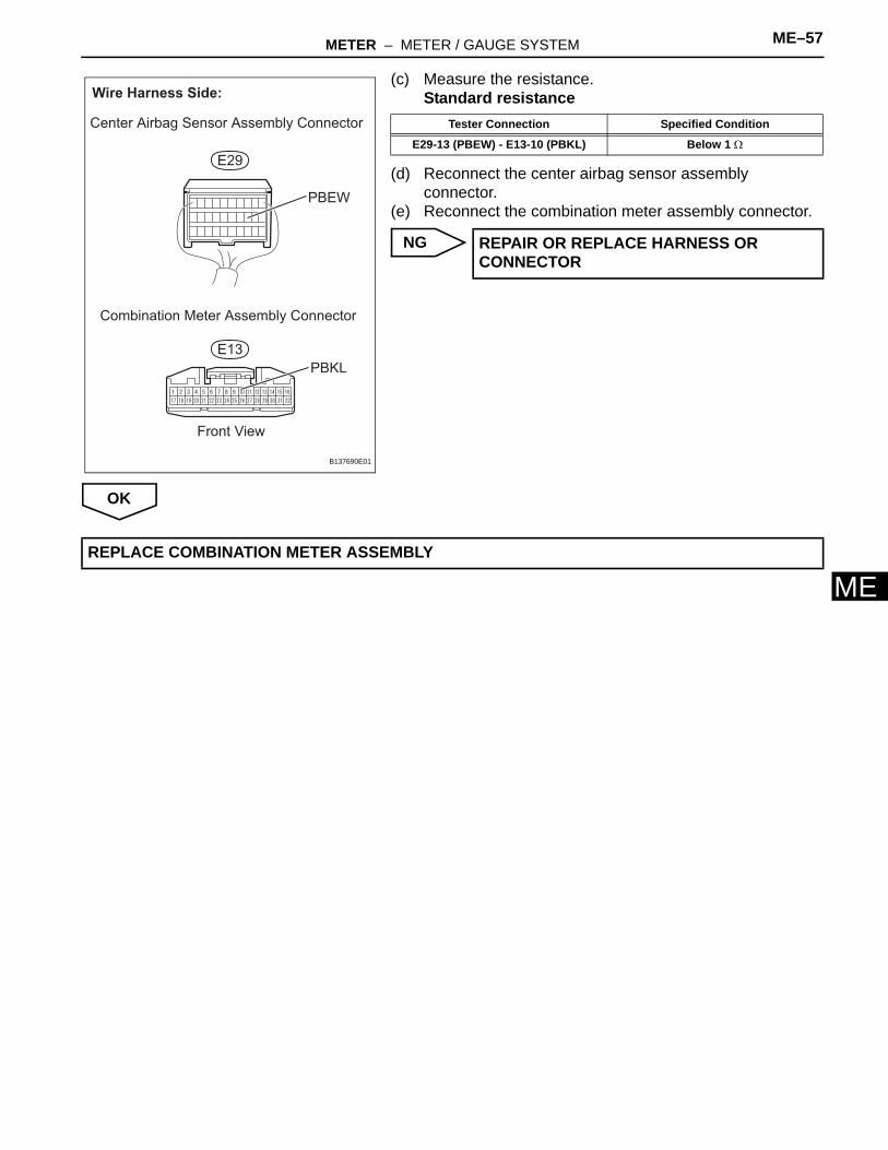
M(c) Measure the resistance.Standard resistance
(d) Reconnect the center airbag sensor assembly connector.
(e) Reconnect the combination meter assembly connector.
NG
OK
Wire Harness Side:
Center Airbag Sensor Assembly Connector
Combination Meter Assembly Connector
Front View
E29
E13
PBEW
PBKL
B137690E01
Tester Connection Specified Condition
E29-13 (PBEW) - E13-10 (PBKL) Below 1 Ω
REPAIR OR REPLACE HARNESS OR CONNECTOR
REPLACE COMBINATION METER ASSEMBLY
ME–58 METER – METER / GAUGE SYSTEM
ME
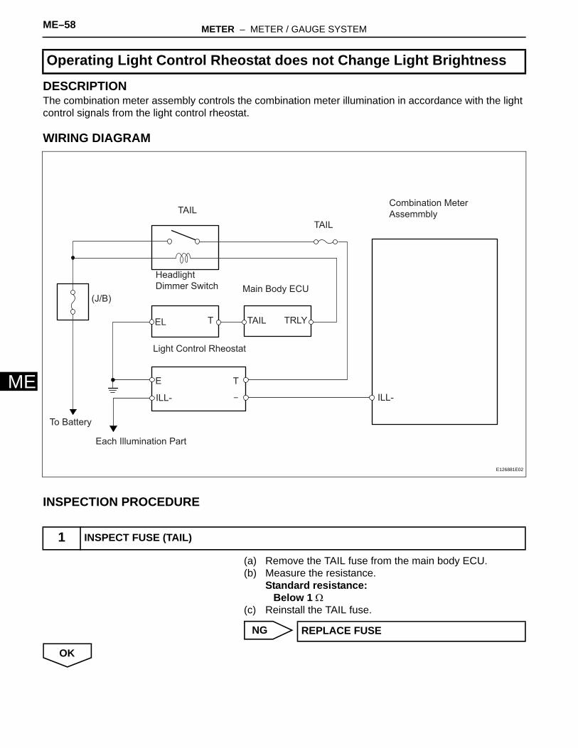
DESCRIPTIONThe combination meter assembly controls the combination meter illumination in accordance with the light control signals from the light control rheostat.
WIRING DIAGRAM
INSPECTION PROCEDURE
(a) Remove the TAIL fuse from the main body ECU.(b) Measure the resistance.
Standard resistance:Below 1 Ω
(c) Reinstall the TAIL fuse.
NG
OK
Operating Light Control Rheostat does not Change Light Brightness
1 INSPECT FUSE (TAIL)
TAIL
Headlight
Dimmer Switch
Light Control Rheostat
Combination Meter
Assemmbly
Each Illumination Part
E
ILL-
T
TEL
ILL-
To Battery
Main Body ECU(J/B)
TAIL TRLY
TAIL
E126881E02
REPLACE FUSE
METER – METER / GAUGE SYSTEM ME–59
E
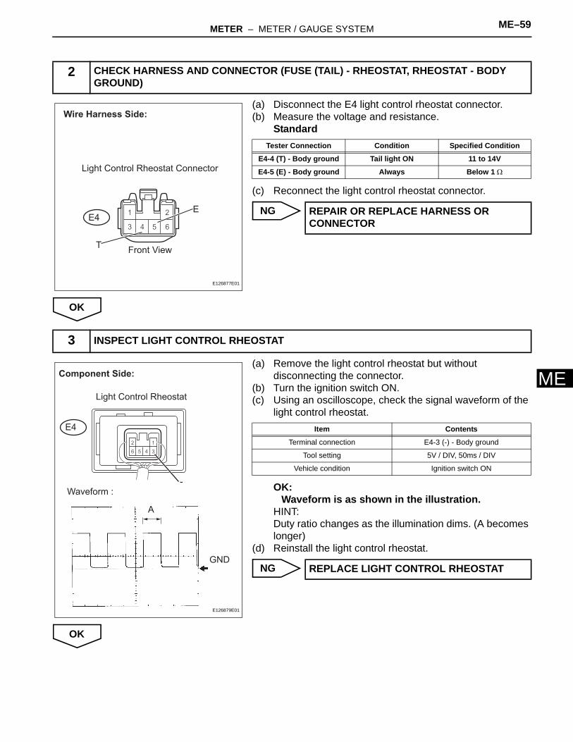
M(a) Disconnect the E4 light control rheostat connector.(b) Measure the voltage and resistance.
Standard
(c) Reconnect the light control rheostat connector.
NG
OK
(a) Remove the light control rheostat but without disconnecting the connector.
(b) Turn the ignition switch ON.(c) Using an oscilloscope, check the signal waveform of the
light control rheostat.
OK:Waveform is as shown in the illustration.
HINT:Duty ratio changes as the illumination dims. (A becomes longer)
(d) Reinstall the light control rheostat.
NG
OK
2 CHECK HARNESS AND CONNECTOR (FUSE (TAIL) - RHEOSTAT, RHEOSTAT - BODY GROUND)
Wire Harness Side:
E4
Light Control Rheostat Connector
TFront View
E
E126877E01
Tester Connection Condition Specified Condition
E4-4 (T) - Body ground Tail light ON 11 to 14V
E4-5 (E) - Body ground Always Below 1 Ω
REPAIR OR REPLACE HARNESS OR CONNECTOR
3 INSPECT LIGHT CONTROL RHEOSTAT
Light Control Rheostat
E4
-Waveform :
A
GND
Component Side:
E126879E01
Item Contents
Terminal connection E4-3 (-) - Body ground
Tool setting 5V / DIV, 50ms / DIV
Vehicle condition Ignition switch ON
REPLACE LIGHT CONTROL RHEOSTAT
ME–60 METER – METER / GAUGE SYSTEM
ME
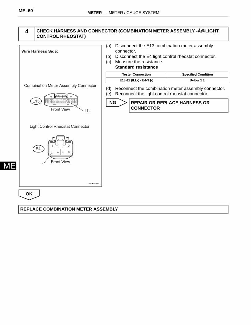
(a) Disconnect the E13 combination meter assembly connector.
(b) Disconnect the E4 light control rheostat connector.(c) Measure the resistance.
Standard resistance
(d) Reconnect the combination meter assembly connector.(e) Reconnect the light control rheostat connector.
NG
OK
4 CHECK HARNESS AND CONNECTOR (COMBINATION METER ASSEMBLY -Å@LIGHT CONTROL RHEOSTAT)
Wire Harness Side:
Combination Meter Assembly Connector
ILL-
Light Control Rheostat Connector
E4
E13
-
Front View
Front View
E126880E01
Tester Connection Specified Condition
E13-11 (ILL-) - E4-3 (-) Below 1 Ω
REPAIR OR REPLACE HARNESS OR CONNECTOR
REPLACE COMBINATION METER ASSEMBLY
METER – COMBINATION METER ME–57
E
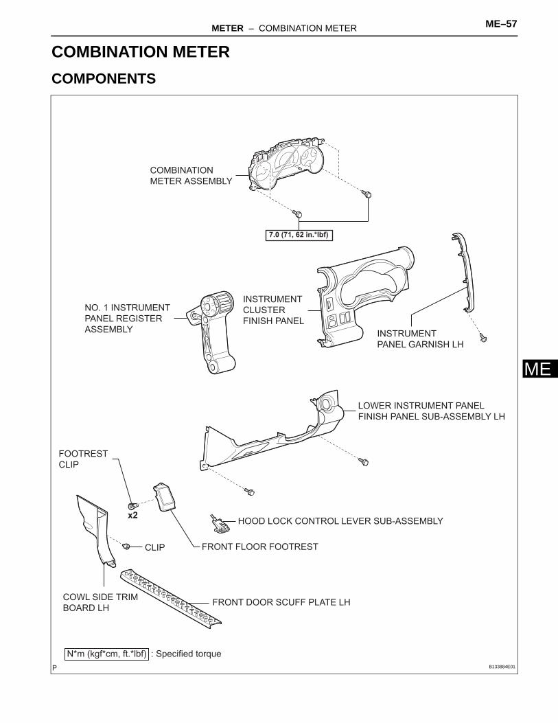
MBODY ELECTRICALMETERCOMBINATION METERCOMPONENTS
COMBINATION
METER ASSEMBLY
7.0 (71, 62 in.*lbf)
NO. 1 INSTRUMENT
PANEL REGISTER
ASSEMBLY
INSTRUMENT
CLUSTER
FINISH PANEL
LOWER INSTRUMENT PANEL
FINISH PANEL SUB-ASSEMBLY LH
HOOD LOCK CONTROL LEVER SUB-ASSEMBLY
N*m (kgf*cm, ft.*lbf) : Specified torque
INSTRUMENT
PANEL GARNISH LH
COWL SIDE TRIM
BOARD LHFRONT DOOR SCUFF PLATE LH
FRONT FLOOR FOOTRESTCLIP
FOOTREST
CLIP
x2
B133884E01

ME–58 METER – COMBINATION METER
ME
COMBINATION METER GLASS
COMBINATION METER
E127928E01
METER – COMBINATION METER ME–59
E
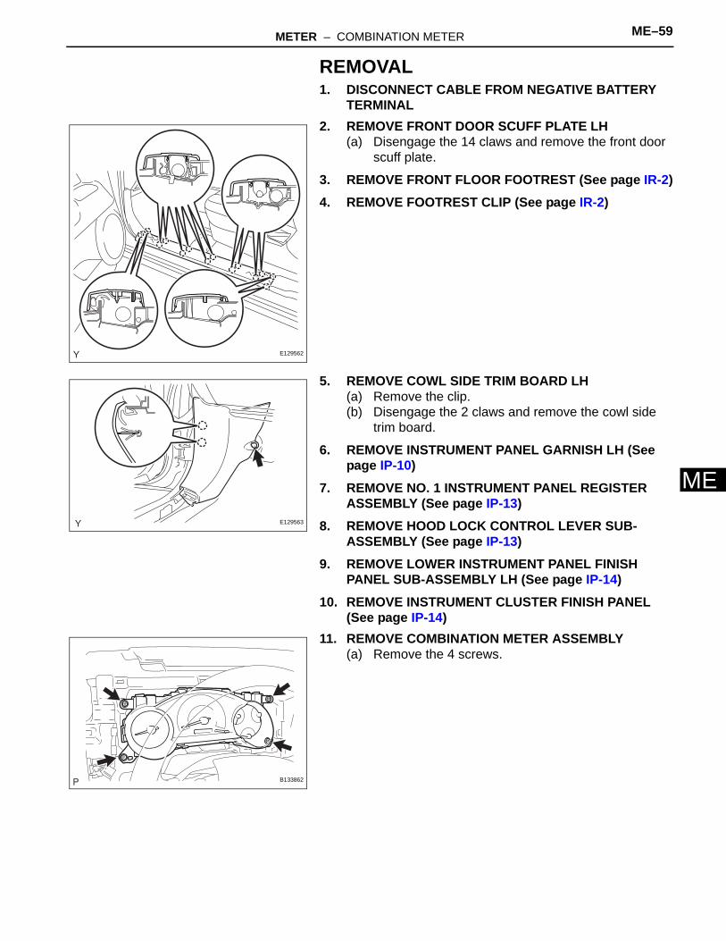
MREMOVAL1. DISCONNECT CABLE FROM NEGATIVE BATTERY
TERMINAL2. REMOVE FRONT DOOR SCUFF PLATE LH
(a) Disengage the 14 claws and remove the front door scuff plate.
3. REMOVE FRONT FLOOR FOOTREST (See page IR-2)4. REMOVE FOOTREST CLIP (See page IR-2)
5. REMOVE COWL SIDE TRIM BOARD LH(a) Remove the clip.(b) Disengage the 2 claws and remove the cowl side
trim board.
6. REMOVE INSTRUMENT PANEL GARNISH LH (See page IP-10)
7. REMOVE NO. 1 INSTRUMENT PANEL REGISTER ASSEMBLY (See page IP-13)
8. REMOVE HOOD LOCK CONTROL LEVER SUB-ASSEMBLY (See page IP-13)
9. REMOVE LOWER INSTRUMENT PANEL FINISH PANEL SUB-ASSEMBLY LH (See page IP-14)
10. REMOVE INSTRUMENT CLUSTER FINISH PANEL (See page IP-14)
11. REMOVE COMBINATION METER ASSEMBLY(a) Remove the 4 screws.
E129562
E129563
B133862
ME–60 METER – COMBINATION METER
ME
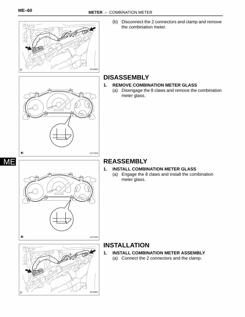
(b) Disconnect the 2 connectors and clamp and remove the combination meter.
DISASSEMBLY1. REMOVE COMBINATION METER GLASS
(a) Disengage the 8 claws and remove the combination meter glass.
REASSEMBLY1. INSTALL COMBINATION METER GLASS
(a) Engage the 8 claws and install the combination meter glass.
INSTALLATION1. INSTALL COMBINATION METER ASSEMBLY
(a) Connect the 2 connectors and the clamp.
B133863
E127929
E127929
B133863
METER – COMBINATION METER ME–61
E
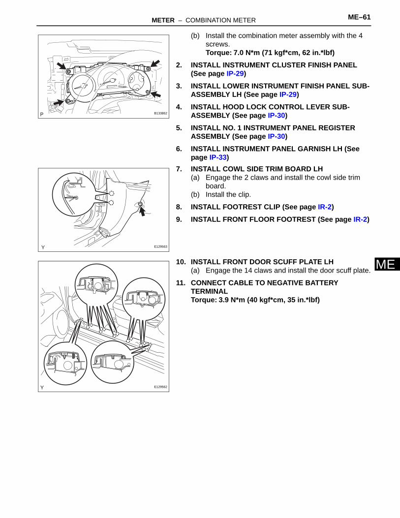
M(b) Install the combination meter assembly with the 4 screws.Torque: 7.0 N*m (71 kgf*cm, 62 in.*lbf)
2. INSTALL INSTRUMENT CLUSTER FINISH PANEL (See page IP-29)
3. INSTALL LOWER INSTRUMENT FINISH PANEL SUB-ASSEMBLY LH (See page IP-29)
4. INSTALL HOOD LOCK CONTROL LEVER SUB-ASSEMBLY (See page IP-30)
5. INSTALL NO. 1 INSTRUMENT PANEL REGISTER ASSEMBLY (See page IP-30)
6. INSTALL INSTRUMENT PANEL GARNISH LH (See page IP-33)
7. INSTALL COWL SIDE TRIM BOARD LH(a) Engage the 2 claws and install the cowl side trim
board.(b) Install the clip.
8. INSTALL FOOTREST CLIP (See page IR-2)9. INSTALL FRONT FLOOR FOOTREST (See page IR-2)
10. INSTALL FRONT DOOR SCUFF PLATE LH(a) Engage the 14 claws and install the door scuff plate.
11. CONNECT CABLE TO NEGATIVE BATTERY TERMINALTorque: 3.9 N*m (40 kgf*cm, 35 in.*lbf)
B133862
E129563
E129562
ME–62 METER – ACCESSORY METER
ME
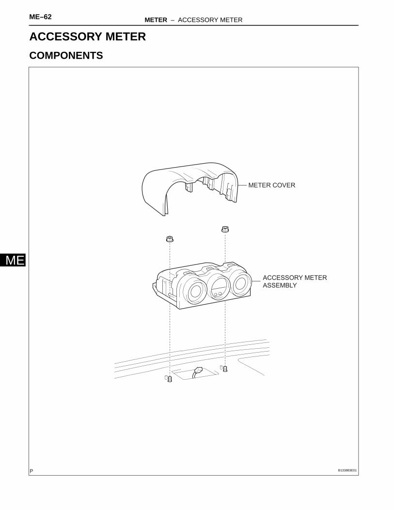
BODY ELECTRICALMETERACCESSORY METERCOMPONENTS
ACCESSORY METER
ASSEMBLY
METER COVER
B133883E01
METER – ACCESSORY METER ME–63
E
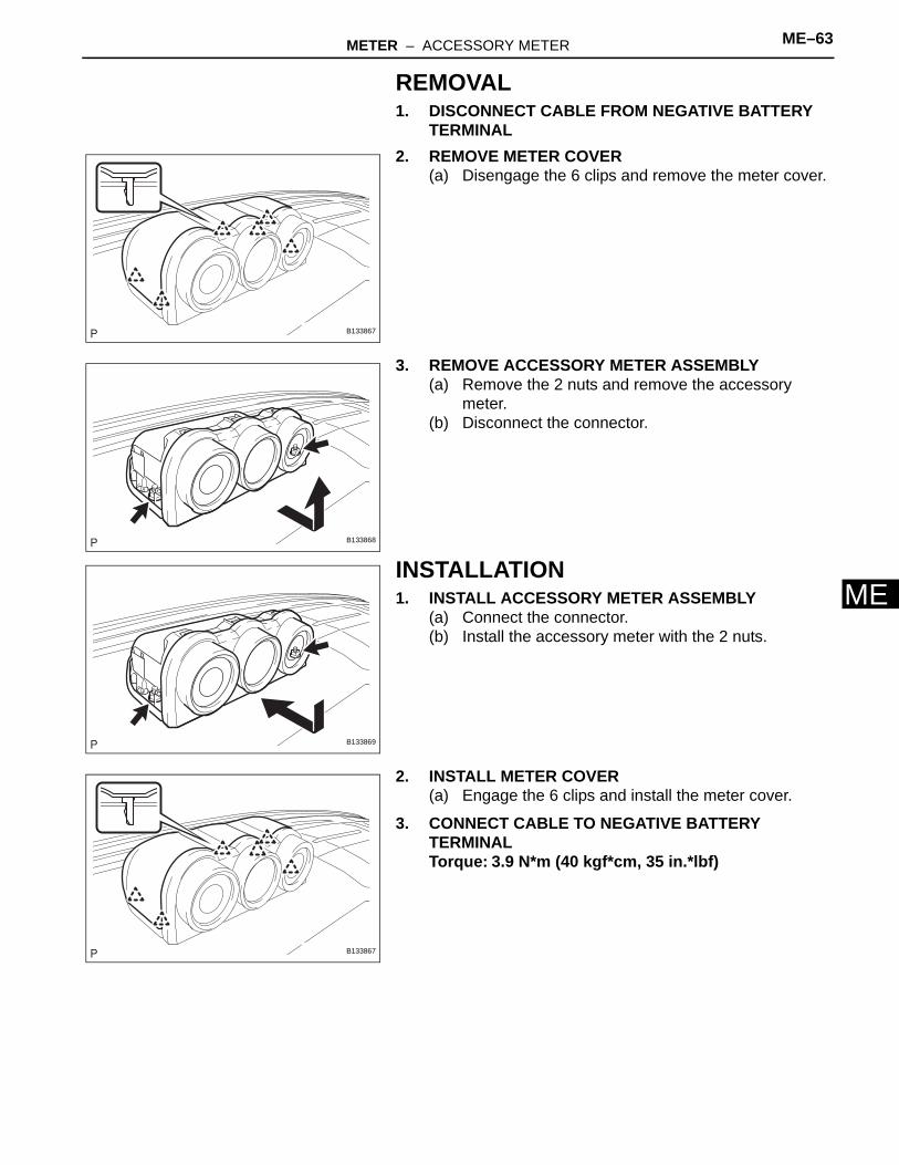
MREMOVAL1. DISCONNECT CABLE FROM NEGATIVE BATTERY
TERMINAL2. REMOVE METER COVER
(a) Disengage the 6 clips and remove the meter cover.
3. REMOVE ACCESSORY METER ASSEMBLY(a) Remove the 2 nuts and remove the accessory
meter.(b) Disconnect the connector.
INSTALLATION1. INSTALL ACCESSORY METER ASSEMBLY
(a) Connect the connector.(b) Install the accessory meter with the 2 nuts.
2. INSTALL METER COVER(a) Engage the 6 clips and install the meter cover.
3. CONNECT CABLE TO NEGATIVE BATTERY TERMINALTorque: 3.9 N*m (40 kgf*cm, 35 in.*lbf)
B133867
B133868
B133869
B133867
ME–64 METER – FUEL SENDER GAUGE ASSEMBLY
ME
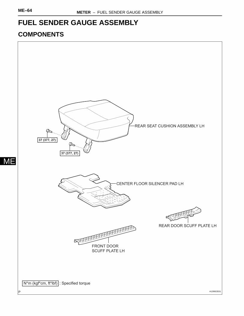
BODY ELECTRICALMETERFUEL SENDER GAUGE ASSEMBLYCOMPONENTS
37 (377, 27)
N*m (kgf*cm, ft*lbf) : Specified torque
FRONT DOOR
SCUFF PLATE LH
REAR DOOR SCUFF PLATE LH
REAR SEAT CUSHION ASSEMBLY LH
CENTER FLOOR SILENCER PAD LH
37 (377, 27)
A129922E01
METER – FUEL SENDER GAUGE ASSEMBLY ME–65
E
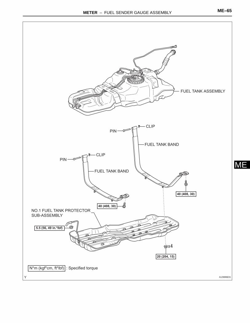
MFUEL TANK ASSEMBLY
FUEL TANK BAND
FUEL TANK BAND
PIN
PIN
N*m (kgf*cm, ft*lbf) : Specified torque
20 (204, 15)
CLIP
CLIP
40 (408, 30)
40 (408, 30)
NO.1 FUEL TANK PROTECTOR
SUB-ASSEMBLY
5.5 (56, 49 in.*lbf)
A129896E01
ME–66 METER – FUEL SENDER GAUGE ASSEMBLY
ME
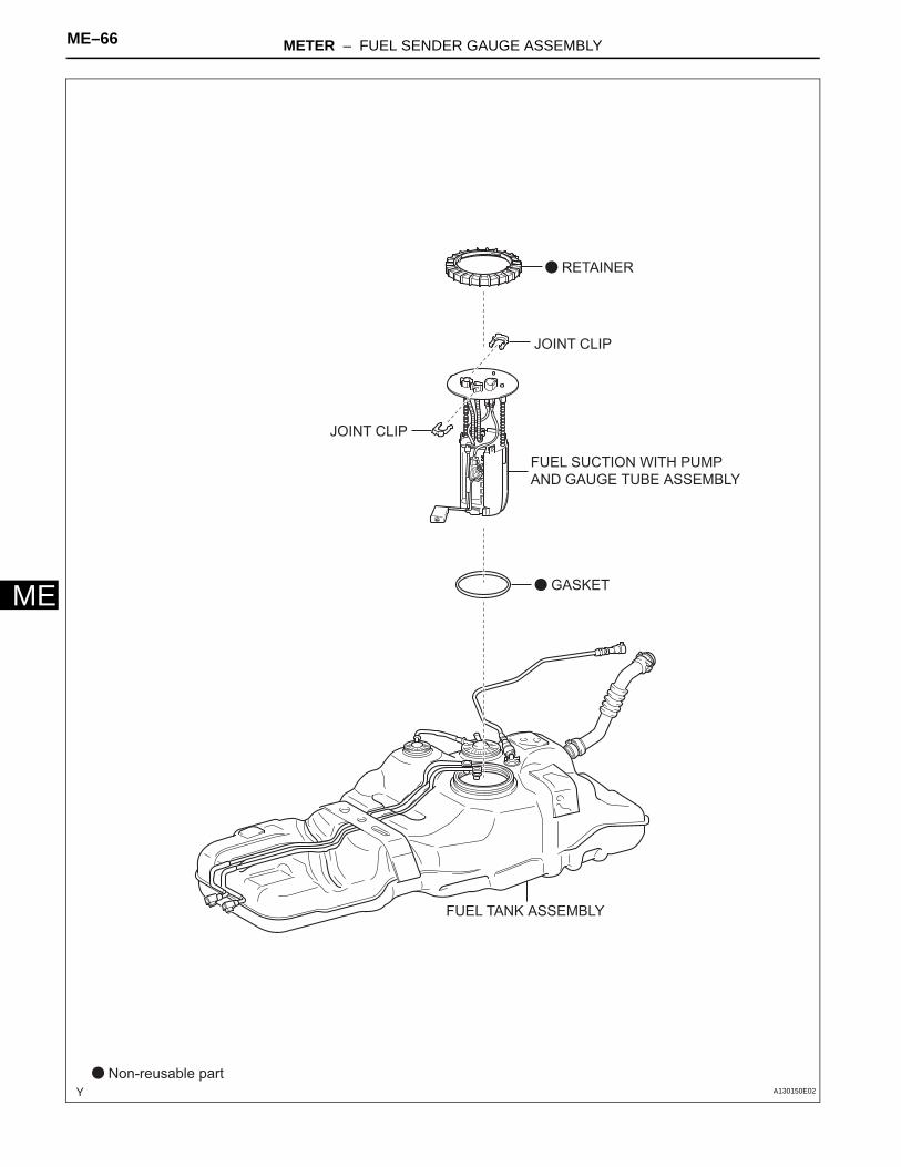
FUEL TANK ASSEMBLY
GASKET
RETAINER
JOINT CLIP
JOINT CLIP
Non-reusable part
FUEL SUCTION WITH PUMP
AND GAUGE TUBE ASSEMBLY
A130150E02
METER – FUEL SENDER GAUGE ASSEMBLY ME–67
E
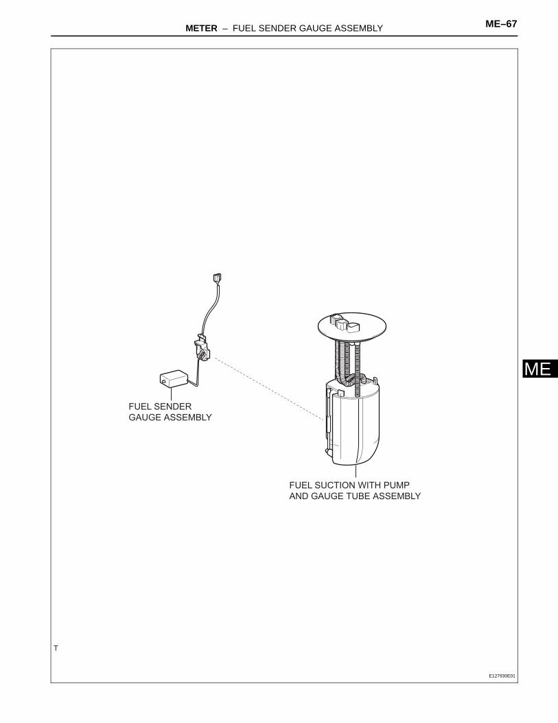
MFUEL SENDER
GAUGE ASSEMBLY
FUEL SUCTION WITH PUMP
AND GAUGE TUBE ASSEMBLY
E127930E01
ME–68 METER – FUEL SENDER GAUGE ASSEMBLY
ME
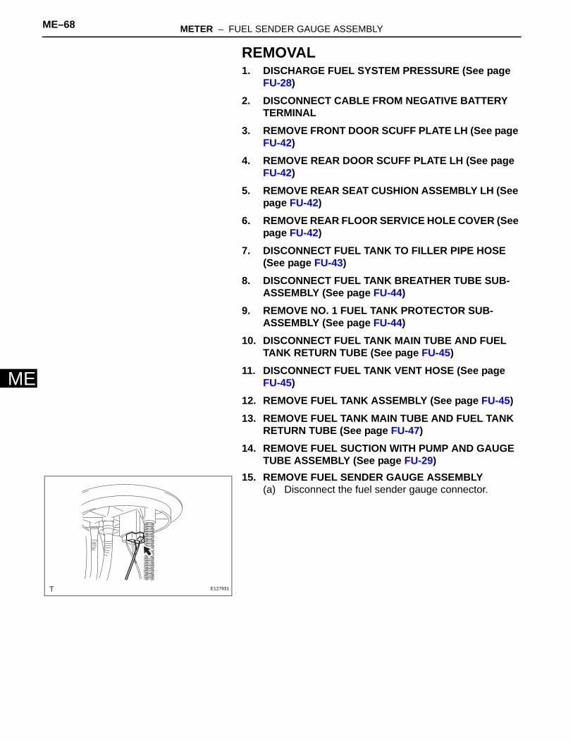
REMOVAL1. DISCHARGE FUEL SYSTEM PRESSURE (See page
FU-28)2. DISCONNECT CABLE FROM NEGATIVE BATTERY
TERMINAL3. REMOVE FRONT DOOR SCUFF PLATE LH (See page
FU-42)4. REMOVE REAR DOOR SCUFF PLATE LH (See page
FU-42)5. REMOVE REAR SEAT CUSHION ASSEMBLY LH (See
page FU-42)6. REMOVE REAR FLOOR SERVICE HOLE COVER (See
page FU-42)7. DISCONNECT FUEL TANK TO FILLER PIPE HOSE
(See page FU-43)8. DISCONNECT FUEL TANK BREATHER TUBE SUB-
ASSEMBLY (See page FU-44)9. REMOVE NO. 1 FUEL TANK PROTECTOR SUB-
ASSEMBLY (See page FU-44)10. DISCONNECT FUEL TANK MAIN TUBE AND FUEL
TANK RETURN TUBE (See page FU-45)11. DISCONNECT FUEL TANK VENT HOSE (See page
FU-45)12. REMOVE FUEL TANK ASSEMBLY (See page FU-45)13. REMOVE FUEL TANK MAIN TUBE AND FUEL TANK
RETURN TUBE (See page FU-47)14. REMOVE FUEL SUCTION WITH PUMP AND GAUGE
TUBE ASSEMBLY (See page FU-29)15. REMOVE FUEL SENDER GAUGE ASSEMBLY
(a) Disconnect the fuel sender gauge connector.
E127931
METER – FUEL SENDER GAUGE ASSEMBLY ME–69
E
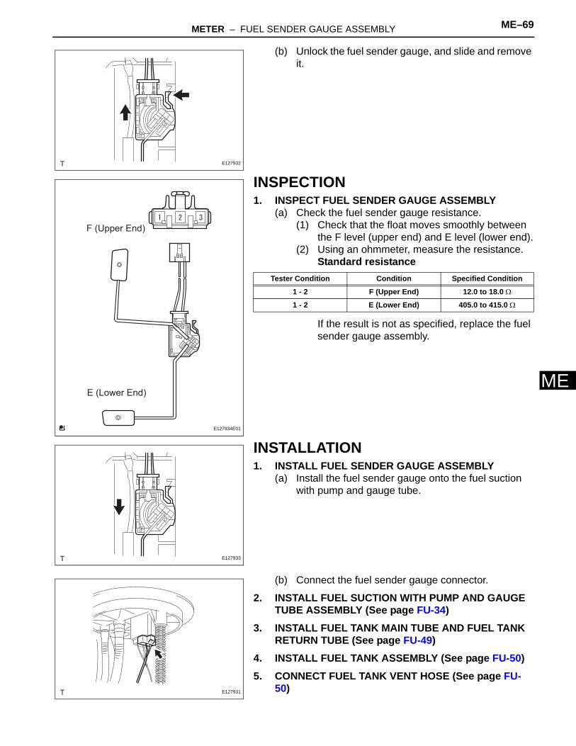
M(b) Unlock the fuel sender gauge, and slide and remove it.
INSPECTION1. INSPECT FUEL SENDER GAUGE ASSEMBLY
(a) Check the fuel sender gauge resistance.(1) Check that the float moves smoothly between
the F level (upper end) and E level (lower end).(2) Using an ohmmeter, measure the resistance.
Standard resistance
If the result is not as specified, replace the fuel sender gauge assembly.
INSTALLATION1. INSTALL FUEL SENDER GAUGE ASSEMBLY
(a) Install the fuel sender gauge onto the fuel suction with pump and gauge tube.
(b) Connect the fuel sender gauge connector.
2. INSTALL FUEL SUCTION WITH PUMP AND GAUGE TUBE ASSEMBLY (See page FU-34)
3. INSTALL FUEL TANK MAIN TUBE AND FUEL TANK RETURN TUBE (See page FU-49)
4. INSTALL FUEL TANK ASSEMBLY (See page FU-50)5. CONNECT FUEL TANK VENT HOSE (See page FU-
50)
E127932
F (Upper End)
E (Lower End)
E127934E01
Tester Condition Condition Specified Condition
1 - 2 F (Upper End) 12.0 to 18.0 Ω
1 - 2 E (Lower End) 405.0 to 415.0 Ω
E127933
E127931
ME–70 METER – FUEL SENDER GAUGE ASSEMBLY
ME
6. CONNECT FUEL TANK MAIN TUBE AND FUEL TANK RETURN TUBE (See page FU-49)
7. CONNECT FUEL TANK BREATHER TUBE SUB-ASSEMBLY (See page FU-51)
8. CONNECT FUEL TANK TO FILLER PIPE HOSE (See page FU-51)
9. INSTALL NO. 1 FUEL TANK PROTECTOR SUB-ASSEMBLY (See page FU-51)
10. INSTALL REAR FLOOR SERVICE HOLE COVER (See page FU-52)
11. INSTALL REAR SEAT CUSHION ASSEMBLY LH (See page FU-53)
12. INSTALL REAR DOOR SCUFF PLATE LH (See page FU-52)
13. INSTALL FRONT DOOR SCUFF PLATE LH (See page FU-53)
14. CONNECT CABLE TO NEGATIVE BATTERY TERMINALTorque: 3.9 N*m (40 kgf*cm, 35 in.*lbf)
15. CHECK FOR FUEL LEAKAGE (See page FU-7)
METER – LIGHT CONTROL RHEOSTAT ME–71
E
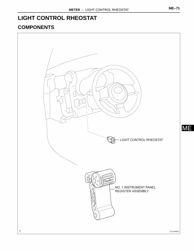
MBODY ELECTRICALMETERLIGHT CONTROL RHEOSTATCOMPONENTS
LIGHT CONTROL RHEOSTAT
NO. 1 INSTRUMENT PANEL
REGISTER ASSEMBLY
E127935E01
ME–72 METER – LIGHT CONTROL RHEOSTAT
ME
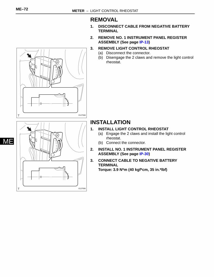
REMOVAL1. DISCONNECT CABLE FROM NEGATIVE BATTERY
TERMINAL2. REMOVE NO. 1 INSTRUMENT PANEL REGISTER
ASSEMBLY (See page IP-13)3. REMOVE LIGHT CONTROL RHEOSTAT
(a) Disconnect the connector.(b) Disengage the 2 claws and remove the light control
rheostat.
INSTALLATION1. INSTALL LIGHT CONTROL RHEOSTAT
(a) Engage the 2 claws and install the light control rheostat.
(b) Connect the connector.
2. INSTALL NO. 1 INSTRUMENT PANEL REGISTER ASSEMBLY (See page IP-30)
3. CONNECT CABLE TO NEGATIVE BATTERY TERMINALTorque: 3.9 N*m (40 kgf*cm, 35 in.*lbf)
E127936
E127936