revolution x - ohwow-arcade.com
TRANSCRIPT

REVOLUTION X2 PLAYER
MIDWAY Manufacturing Company reserves the rights to make modifications and improvements to itsproducts. The specif ications and parts identif ied in this manual are subject to change without notice.
I

REVOLUTION X
Monday, November 11, 1996: The New Order Nation - a corrupt alliance of government and big business led by
“Headmistress Helga” - has abducted rock superstars Aerosmith from a Los Angeles concert hall and launched
an offensive to control the worlds youth. Legions of NON party troops now control the world’s cultural and
Bschnological centers.
You, one of the worlds last free youth, are armed with an AUTOLOAD MULTI-CD LAUNCHEWSONIC
ASSAULT WEAPON. You must batt le al l New Order Forces to get backstage at LAS “Club X” to rece ive a
secret message left for you by AEROSMITH! b
Continuing on, you illegally requisition a New Order Chopper and take it on a devastating joy ride above
the streets of LA. You must ul t imately locate AEROSMITH’S “X” car where you wil l receive another message
from AEROSMITH, lett ing you choose your next destination from the Pacif ic Rim, the Amazon and the Middle
E:ast.
When you have successfully Completed all four levels of the game, you arrive on stage at Wembley
P,rena in England for the f inal surprising confrontation with Headmistress Helga. You must defeat Headmistress
Flelga to overthrow the New Order Nation and make you contribution to the Revolution!
- Remember, Music Is The Weapon!
game rules...
You need two credits to start a game, and two credits to continue.
Use trigger and yellow Bomb button on gun in combination to discover secret weapons.
Look for hidden passages and entry ways into unknown areas.

TABLE OF CONTENTSSection 1 Operation and Troubleshooting
Rules .._...................................................................,,........,..................................................,.,.,...,...... ,,Safety . . . . . ..__...__....._...........,......,,,..........,....................,.,.,..,.,....,.,............,....,,...,.......,..........,.,....,,. lVSetup Procedure .._...........___,.,..,...............,.,...........,...................,....,..,,............,.,,......,..,,.........,,, t-2
Installation & Inspection ._....,_......____._..............,,............,.....,,.....,.,......,.....,,..,..,.,....,,..... t -2Location Requirements .__....,.__...._....................,..,.....,..........,,.,....,..,....,..,................,..... 1-2Cabinet Assembly Diagram __..........................,,..........................,,.......,,................,,,...... l-4
Servicing .._..___,,...,.............,..,...,......,....................,.........................,........,....,...,......,....,..........,.,. 1-6Game Features . .._..........__..............................................................,.,.........................,.,.....,,....... 1-S
Start ing-up ..____.,_._........,........,.,........................,..,.,..,.,.............,..,...,,....,,,,..........,,.....,,... 1-SPlayer Controls .__........,_......_.......,...............................,.................,..,....,.......,................. 1.8Control Panel Diagram .,......,_...__,..._........................,..,.,,.....,....................,,.................,.. 1-S
Game Operations ,_......_....____,__,.....,.............,..............................,.............................,.....,............ t-9Control Switches . . .._..__...._...................,........,,...,.......,,......,,......,............,,.......,..,........ 1-gControl Switch Location Diagram .._......._.____..._....,...,..,.........,.......,.... - .,____.__._.,..,........... 1-g
Menu System Operation . .._._.._._.......__......................... ~ ,.___...._._......__........................................... 1-t 0Operation __......__._......_.................,.....................,.......,.................,,.........................,....... 1-j 0Main M e n u . . . . . . . . . . . . . . . . . . . . . . . . . . . . . . . . . . . . . . . . . . . . . . . . . . . . . . . . . . . . . . . . . . . . . . . . . . . . . . . . . . . . . . . . . . . . . . . . . . . . . . . . . . . . . . . . . . . . . 1-10Diagnostic Tests . . . . . .._..._................................................................................................. t-11
Switch Test . .._...._......_...................................,..........................,......................... 1-11DIP Switch Test & Tables . . . . . . . .._........................................................................ t-12C P U Test & Sound Test . . . . . . . . . ..__........................................................................ t-13Monitor Patterns Test . . .._........._._...................................................................... 1-14Driver Board Test & Burn-in Test ____...._.....__,............,....,,.,...............,........,........ 1-t 5
Coin Bookkeeping _.........__.._._...........................,,,..,.,,.........,......,.....................,.............. 1-t SGame Audits ..,__..,._..,_,...._......,.,....,......................,,..............,.....,.,................................. 1-17Game Adjustments .._..,.___.,._____..............,..........,........................,.................................... 1-20
Standard Pricing Table . . . . . . . . . . .._......................................................................... j-23Custom Pricing Table _.___.,.___.....__...................,....,..........,.,.....,.................,........ f-24
Uti l i t ies .__..,_..,,.._,._.__....,.,..,.,.,..,......,......,,.,......,.........,...,.....,..........,.......,.....,.........,....... 1-25Calibrate Guns ___,...._____ .__.,.____..._______..............,................,............................................. t -26Hardware Info _....,.__.___..,....,.,...........,.,...,.................,.........,...........,,............................... 1-27Adjust Volume . . . .._...__._......_..........................................,....,,...............,........,.................. 1-28
Troubleshooting ._._...,,,_._.._.,..............................,,.,..,.....,.............,..,.......,..........,,........................ 1-29
Section 2 Parts InformationCabinet & Manuals ,.__._.__,._..,,.__,........,.,....,...............,....,.,.....,.........,.....,,,................................... 2-2Control Panel Assembly, Electronic Rack, Speakers, Transformer Assembly, FluorescentLamp Assembly ,.....,,._..,_.__..,.,,..........,........,......,...................,,.....,...........,,.....,........................... 2-3Cables & Monitor __...__..,_,.._..___,.............................,..............,....................................................... 2.4Power Supply _,,,__..__..,,....__.,,.........,...,,,..,.,........,,...,.....,.,........,......,,.................,......................... 2-5Video CPU Board _._...__.,.__..._..,.............................,..,...,,................,............................................. 2-SVideo Sound Board ,_..._.._,.,_,....._,......,,.....,...............,.....,.,....,.........,......,.................................... 2-SGun Coil Driver Board ..__...._,,_._.,__.,.........,....................,.,,...,....................................................... 2-11)Gun Assembly ._..__._..,_._,._._,,.......,....,,,..............,....,......,......,.,..................................................... 2-12
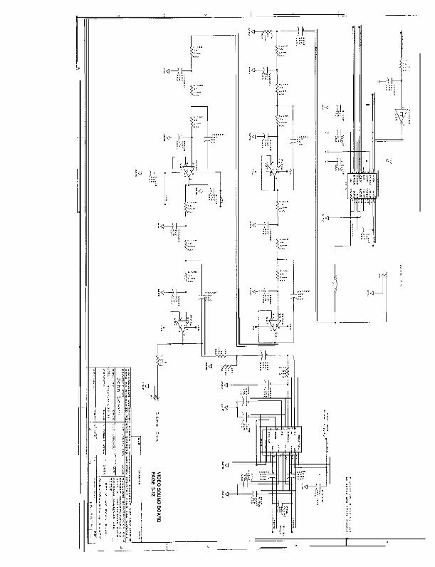
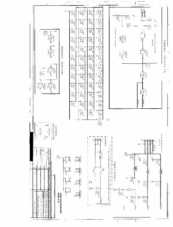
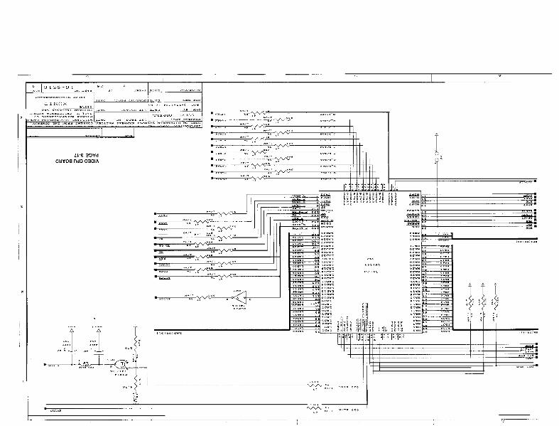
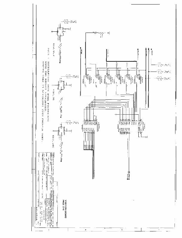
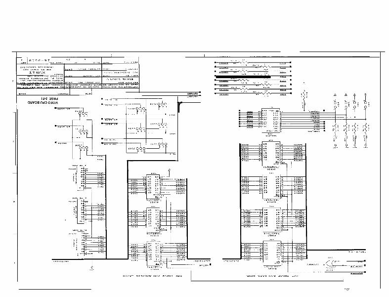
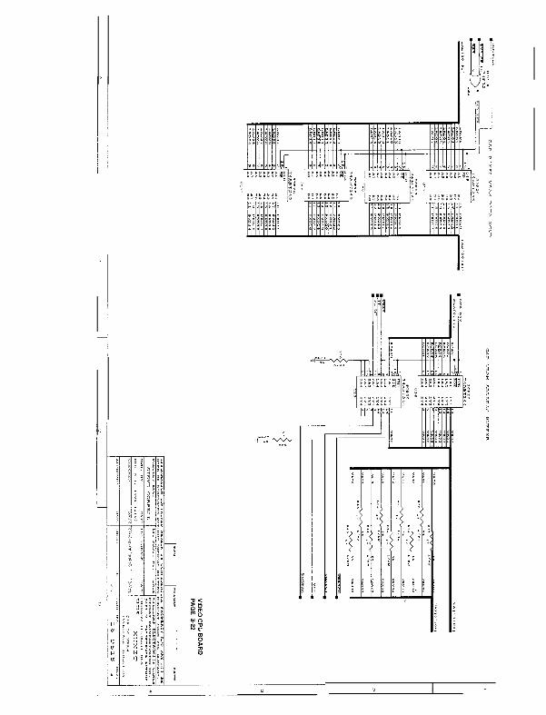
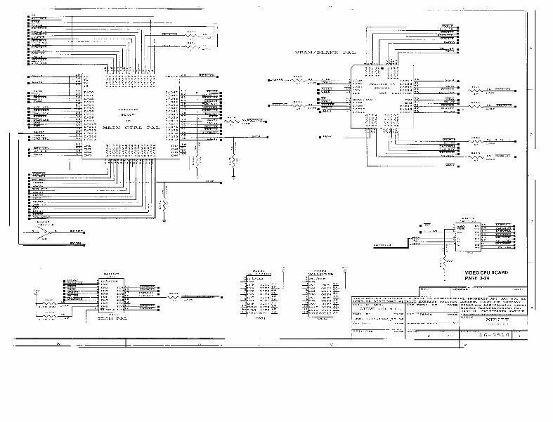
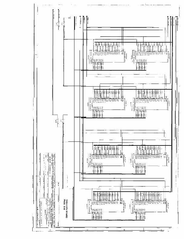
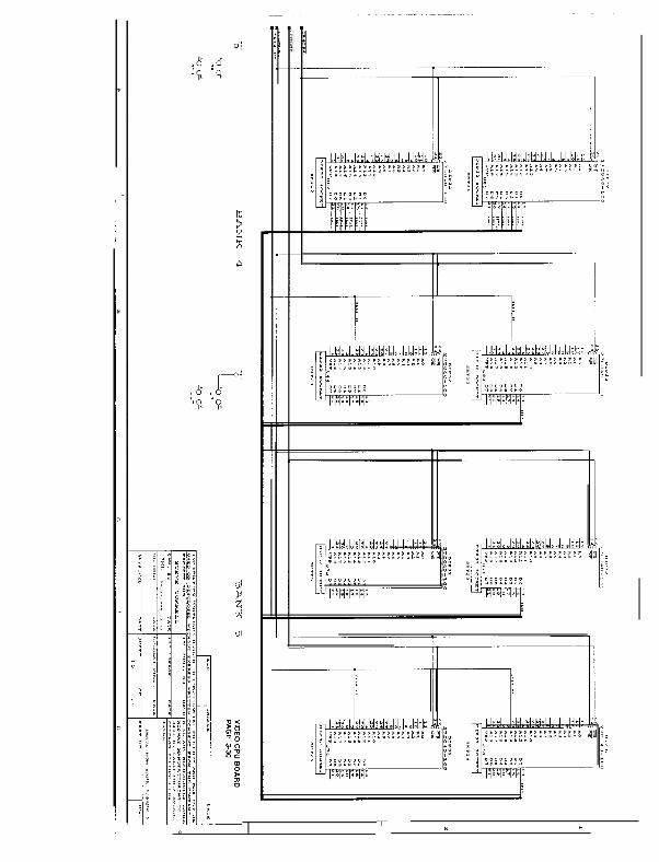
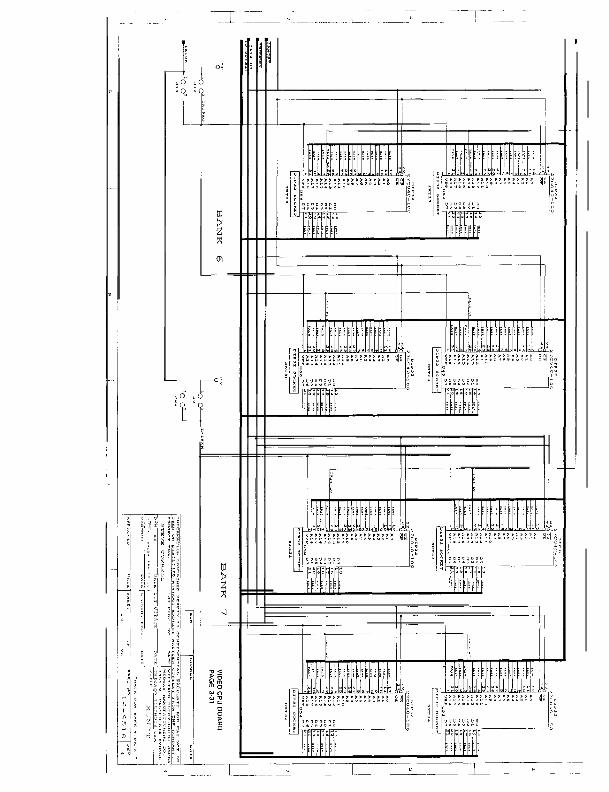
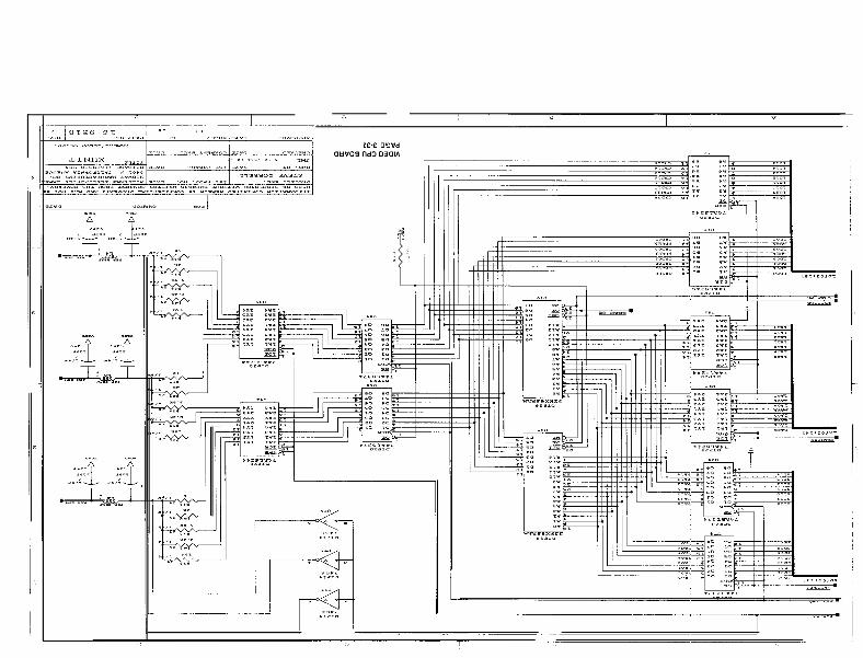
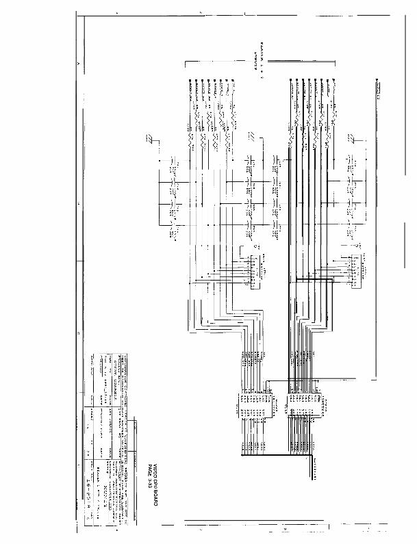
Section 3 Diagrams and SchematicsJAMMA Chart __.,,,...,_..,.,._._..,....,.,...,.......,....................,............................................................... 3.2Interboard Wiring Diagram __.__._.,__...,...__.................,................................,.......,,.......................... 3-3Power Wiring Diagram & Transformer Chart .._..,__.,,._,.,__._.....,,.................................................... 3-4Cabinet Wiring Diagram ._.._...,,.._.._..._..,.,.................,....,.....,........................................................ 3-5Gun Coil Driver Board Schematic ,___.___.,..._,.._...........,....,....,.........,,............................................ 3-6Video Sound Board Schematic ._..,..___...._,,,._.,...........,......,,,........................................................ 3-gVideo CPU Board Schematic ..__,...,,.......__......... . . . . ..____......._.,..................................................... 3-16Electronic Rack Assembly _..,.___._._.._..,............,,........,..........,,.......,.............................................. 3.42
I l l0 Copyright 1934 MIDWAY Manufaclurlng Company

SAFETY NOTICESThe following safety instructions apply to all game operators and service personnel. Specif ic warningsand cautions will be found throughout this manual where they apply. We recommend that you read thispage before preparing your game for play.
WEIGHT. This game cabinet weights apx. 425Lbs crated
MIRROR. This game cabinet contains a front-silvered mirror and a horizontal monitors
AC POWER CONNECTION. Before connecting the game to the AC power source, verify the “l inevoltage selection chart” jumper wires are installed correctly for the l ine voltage in your area. For detailsrefer to Section 3.
PROPERLY GROUND THE GAME. To avoid electrical shocks, do not plug in the game unti l i t hasbeen inspected and properly grounded. MIDWAY games should only be plugged into a grounded 3-wire outlet. Shocks may result i f the control panel is not properly grounded! After servicing any parts onthe panel, assure that the ground wires are secure. Only then should you lock up the game.
DISCONNECT POWER DURING REPAIRS. To avoid electrical shock, disconnect the game from theAC power source before removing or repairing any part of the game.
USE THE PROPER FUSE. To avoid electrical shock, use the replacement fuse which is specified inthe parts l ist for this game. The replacement fuse must match the or iginal fuse in fuse type, voltagerat ing, and current rat ing.
MONITOR PRECAUTIONS. When removing or repairing the monitor, extra precautions must be takento avoid electrical shock because high voltages may exist within the monitor circuitry and cathode raytube (CRT) even after power has been disconnected. Do not touch internal parts of the monitor withyou hands or metal objects! Always discharge the CRT by the fol lowing method: Attach one end of alarge, well- insulated, 20kV jumper to ground. Momentari ly touch the free end of the grounded jumper tothe anode by sliding it under the anode cap. Wait two minutes and discharge the anode again.
TRANSFORMER. This video game uses a monitor that requires an isolat ion transformer. This trans-former also provides power for the gun coils and the audio amp.
HANDLE FLUORESCENT TUBE AND CRT WITH CARE. If you drop a fluorescent tube or CRT and itbreaks, i t will implode! Shattered glass can f ly eight feet or more from the implosion.
ATTENTION !
PROPERLYATTACH ALL CONNECTORS. Be sure thaf the connecfors on each printed circuit board(PCBJ are properly connected. If they do nol slip on easifx do nof force them. A reversed connectormay damage your game and void the warranty. A// connecfors are keyed fo fit specific pins on eachboard.
I V

REVOLUTION X
S E C T I O None
Operation
l - l

=SETUP PROCEDURE
INSTALLATION & INSPECTION
Game LocationRequirements
Power .Ie!?2@ &m@g!dDomestic 115V Q 60 Hz 32” F to 100’ Not to exceed 95% relative.Foreign 230V 0 50 Hz (0’ c to 38” C)
1, Remove all i tems from the shipping containers and set them aside. Inspect the exterior of the cabinet and---L--I - - - -the corwu~ panei for anji damage: Removethepackinymater*i from around the guns.
2. The coin door keys are attached to one of the guns. Unlock and open the coin and cash box doors.Remove the spare parts stored in the cash box and remove the rear door keys located on a key hook insidethe coin door. >
3. Remove the screws holding the rear door then unlock and remove the door. Be careful. The marquee andthe marquee g/ass are shipped in a cardboard carton attached to the rear door. Inspect the cabinet interiorfor any signs of damage. Check all major assemblies to assure that they are mounted securely.
4 . Refer to the Cabinet Wiring Diagram (Section 3), and check to see that all cable connectors are correctlysecured. Do not force connectors. Watch for damaged connectors and avoid making reversed connec-t ions.
5. If a padlock is desired, turn the rear door hasp so that it protrudes from the hole in the back of the cabinet.Remove the two nuts inside the cabinet, at the top and middle of the rear door opening. Then slide the haspoff of the bolts. Turn the hasp, slide it back on the bolts and replace the nuts.
6. Slowly, f l ip the header forward. Be careful. Do not /et the header s/am down onto the cabinet. Fasten theheader into place with two 1/4-20x1-1/2 hex-head bolts (shipped in the cash box). Remove the marqueecarton from the rear door. Unscrew and remove the black marquee retaining strip at the top of the header.Fit the marquee into the grooves, then sl ide the glass in in front of the marquee. Replace the marqueeretaining strip.
7. Next, locate the four leg levelers among the spare parts in the cash box. There are four threaded holes onthe bottom of the cabinet; one in each corner. Place one leg leveler (with its hex nut) in each of the threadedholes. Lower each leg leveler until the cabinet is stable and level.
!! WARNING !!The cabinet is top heavy. Do not t i l t the cabinet.
8. Determine the value of your l ine voltage with a meter. Then, check the power input wires to the main powersupply transformer. Be sure they are connected to the taps which correspond to your local l ine voltagevalue. If necessary, reconnect the power input wires to the transformer in accordance with the TransformerChart in Section 3.
9. Lay the line cord (connected to the power chassis) in the slot along the bottom edge of the rear cabinet door.Replace the rear cabinet door. Close and lock the front coin and cash box doors. Plug the game into agrounded (3-terminal) AC wall outlet. Switch on the game, using the On/Off switch located on the upper leftrear of the cabinet.
1-2
1 0 . I f the fol lowing message appears on the screen when the game I S turned on, the guns must be calibrated.
“CMOS RAM Error”Unable to read gun calibration values.
NOTECheck the gun calibratton when you receive the ga,me. Guns might of been jarred during shipping and be inneed of calibrakx The guns are calibrated f rom t,+e factory. However, if you change PC boards or replaceROMs, RAMS, or the battery they must be re-calibrated.-Guns do not operate unless they are calibrated. DONOTATTEMPT TO CALIBRATE BY OPENING THE GUNSANDADJUSTING THE POTENTIOMETERS MANU-ALLY, GUN CALIBRATION INSTRUCTIONS ARE ON PAGE I-26 OF THl.5 MANUAL.
l-3

CABINET ASSEMBLY
FLUORESCENT LAMP ASSY.
SPEAKER GRILLE
VlEWlNG GLASS
CONTROL PANEL’
COIN DOOR -
CASHBOX DOOR -
Front View
1 - 4
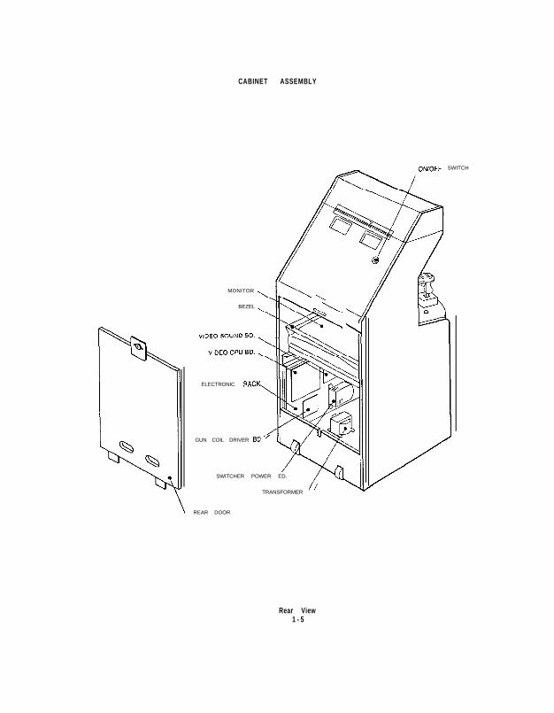
CABINET ASSEMBLY
MONITOR
BEZEL
ELECTRONIC RACK
GUN COIL DRIVER SD. ’
SWITCHER POWER ED.
TRANSFORMER/
REAR DOOR
\
\\
ON/OFF SWITCH
Rear View1 - 5
-~-.
SE R V I C I NG
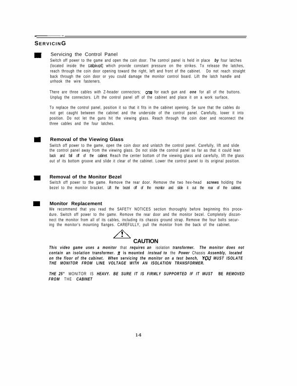
Servicing the Control PanelSwitch off power to the game and open the coin door. The control panel is held in place by four latches(located inside the cabrnet) which provide constant pressure on the strikes. To release the latches,reach through the coin door opening toward the right, left and front of the cabinet. Do not reach straightback through the coin door or you could damage the monitor control board. Lift the latch handle andunhook the wire fasteners.
There are three cables with Z-header connectors; lone for each gun and one for al l of the buttons.Unplug the connectors. Lift the control panel off of the cabinet and place it on a work surface,
To replace the control panel, position it so that it f its in the cabinet opening. Se sure that the cables donot get caught between the cabinet and the underside of the control panel. Carefully, lower it intoposition. Do not let the guns hit the viewing glass. Reach through the coin doer and reconnect thethree cables and the four latches.
Removal of the Viewing GlassSwitch off power to the game, open the coin door and unlatch the control panel. Carefully, l ift and slidethe control panel away from the viewing glass. Do not slide the control panel so far as that it could leanback and fall off of the cabinet. Reach the center bottom of the viewing glass and careful ly, l i f t the glassout of its bottom groove and slide it clear of the cabinet. Lower the control panel to its original position.
Removal of the Monitor BezelSwitch off power to the game. Remove the rear door. Remove the two hex-head screws holding thebezel to the monitor bracket. Lift the bezel off of the monitor and slide it out the rear of the cabinet.
Monitor ReplacementWe recommend that you read the SAFETY NOTICES section thoroughly before beginning this proce-dure. Switch off power to the game. Remove the rear door and the monitor bezel. Completely discon-nect the monitor from all of i ts cables, including its chassis ground strap. Remove the four bolts secur-ing the monitor’s mounting f langes. CAREFULLY, pul l the monitor from the back of the cabinet.
ACAUTION
This video game uses a monitor that requires an isolation transformer. The monitor does notcontain an iso lat ion transformer. It is mounted instead to the Power Chassis Assembly, locatedon the f loor of the cabinet . When servicing the monitor on a test bench, YOU MUST ISOLATETHE MONITOR FROM LINE VOLTAGE WITH AN ISOLATION TRANSFORMER.
THE 25” MONITOR IS HEAVY. BE SURE IT IS FIRMLY SUPPORTED IF IT MUST BE REMOVEDFROM THE CABINET
1-6
m Removal of the MarqueeSwitch off power to the game. Remove the hex-head screws from the black marquee retaining str iplocated on top of the header. Remove the strip and carefully lift the marquee and the marquee glassfrom the top of the header. Store the marquee carefully to prevent damage.
m Removal of the Fluorescent Light AssemblySwitch off power to the game. Remove the marquee glass and the marquee. The f luorescent bulb isnow accessible for replacement. Remove the plastic lamp locks. Grasp the bulb, give it a quarter turn,and remove it from its socket. Carefully, place a new bulb into the socket, and turn to reinstall.
To remove the entire l ight f ixture, disconnect the f luorescent l ight assembly from rts power cable. R e -move the screws that hold the assembly to the cabinet then l i f t out the assembly.
!! WARNING !!I f you drop a f luorescent tube and it breaks, i t wil l implode! Use care in handling.
m Removal of the SpeakersSwitch off power to the game. Remove the marquee and the marquee glass. Unbolt the header fromthe cabinet and fl ip it back unti l i t rests on the cabinet. The speakers come out from the top of thecabinet. Be sure to disconnect the cabling and remove the nuts on the mounting screws before at-tempting to remove the speakers from the enclosure. Carefully, reinstall the seals upon completing anytask in the speaker enclosure.
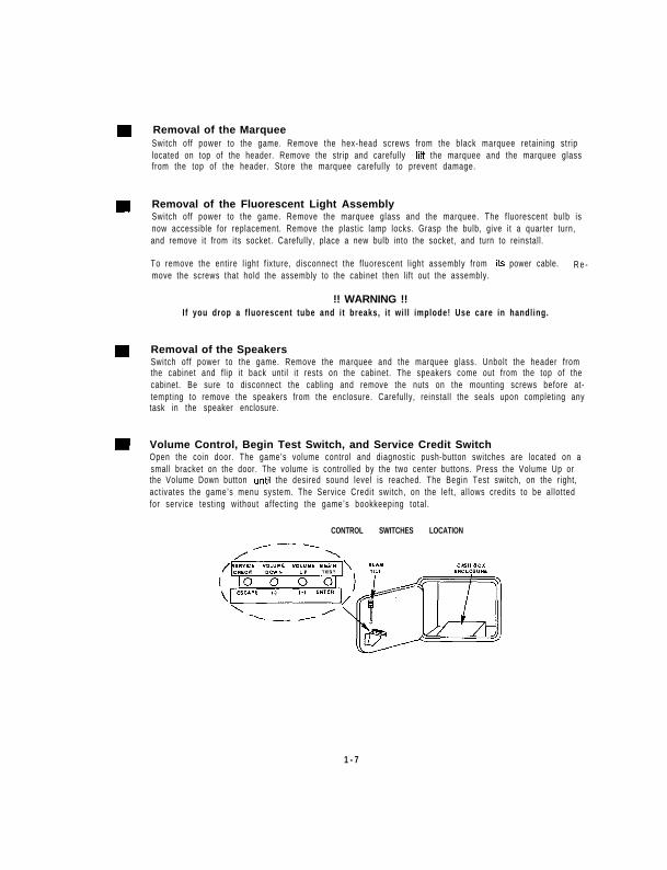
m Volume Control, Begin Test Switch, and Service Credit SwitchOpen the coin door. The game’s volume control and diagnostic push-button switches are located on asmall bracket on the door. The volume is controlled by the two center buttons. Press the Volume Up orthe Volume Down button untrl the desired sound level is reached. The Begin Test switch, on the right,act ivates the game’s menu system. The Service Credit switch, on the left , al lows credits to be al lottedfor service test ing without affect ing the game’s bookkeeping total.
CONTROL SWITCHES LOCATION
1 - 7

GAME FEATURES
STARTING UPSwitch On power to the game. A “rug” pattern appears on the CRT screen. When the “rug” pattern ends, thescreen shows CHECKING SCRATCH RAMS, and then CHECKING ROMS. The next screen shows REVDLIJ-TION X revision level, CMOS test, coin sett ings and the serial number of the game. The software also performsa securi ty test. I f the securi ty test fai ls, the game wil l not power up. After the Start-up tests have beensuccessfully completed, the game begins the Attract Mode.
,___a AL_ _-_IIISUIL ule desiied drnuuni oi coins, biiis oi tokens. Seteci which-piqerrreceives the-credit by pressing theappropriate Start button.
When an error is detected during the Start-up tests, game start-up does not progress, and an error messageappears on the screen.
PLAYER CONTROLSStart ButtonEach player has two Start buttons located to the left and right of the guns. The Start buttons al low one or twoplayers to begin or continue play.
GUMEach player has a gun. The guns allow the player to aim for and shoot at moving targets,
Bomb ButtonsEach player has a bomb button located on the front left side of their gun. This button allows the player to f irebombs at targets.
LEDsEach player has two red LEDs located on each side of their gun. The LEDs are il luminated during game play.
NOTEDiscover secret weapons by using trigger and Bomb button combinations.
Discover hidden passages and entry ways into unknown areas.
CONTROL PANEL
,2 START \J---
%!A
@aobleBUrrON
/
l -8

GAME OPERATION
The REVOLUTION X Control switches are located inside the coin door
CONTROL SWITCHESControl switches are located on a bracket inside the coin door. Each control switch (except Slam Tilt) performstwo functions: one during normal operation and one during the menu system operation.
NORMAL OPERATIONThe Slam Ti l t switch detects any forceful vibrat ions against the coin door. This eiiminates pounding ior freegames.
The Volume Down and Volume Up push-button switches increase or decrea?e the volume level of the musicand speech. The volume level can be adjusted during the Attract Mode or during menu system operation. Forgreater profi ts, set your game’s volume level at a nice loud sett ing.
The Begin Test push-button switch enters the game’s menu system. Press the Begin Test switch to access anyof the menu system funct ions.
The Service Credit push-button switch is a special feature switch that al lots credit without affecting the game’sbookkeeping total.
NOTE_The coin door must be open for the control switches to work.
MENU SYSTEM OPERATIONThe (-1 and (+) push-button switches move the cursor up and down the screen, raise and lower the volumelevel, and increase and decrease adjustment setting values.
The Enter push-button switch moves into the next menu. This switch also locks in an adjustment sett ing value.
The Escape push-button switch backs out of a menu and returns to the previous menu.
Con&o/pane/ switches can substi tute for the control switches in the coin door.Player 1 Sfarf button = (-); Player 2 Start button = (+); Bomb bufton = Escape; Trigger = Enter.
CONTROL SWITCHES LOCATION

=MENU SYSTEM OPERiTlON
OPERATIONAll game audits, adjustments and dragnostrcs are options of the Main Menu. Each option, in turn, has its ownmenu that lrsts several chorces which you may act upon as desired.
Press the Begin Test switch on the coin door or close switch #8 of DIP switch bank #2. to open the Main Menu(shown below). Game adjustments, bookkeeping and diagnostics are all accessible from this menu.
Press the (-) button, to move the cursor up the menu screen. Press the (+) button to move the cursor down thescreen. Notice that the options are highlighted in sequence. Press the Enter button to open a highlightedoptron. On/y /rigblighted options can be opened.
T u exit the Main Menu, press the (-) or (+) button to select EXIT TO GAME OVER, then pressthe Escape button.It is necessary to turn off switch A+8 of DIP switch bank #2, if this switch was used to enter the menusystem.
l-10

DIAGNOSTIC TESTSTo enter the diagnostic tests from the Main Menu, use the (-) or (+) button to highlight Diagnostic Menu,press the Enter button to open the menu. The Diagnostic Menu is shown below.
then
Switch TestThe Switch Test allows the operator to test the switches on the control panel and in the coin door
Press the (-) or (+) button to highl ight the Switch Test, then press the Enter button to begin the test.
During the Switch Test the top of the screen shows the control panel switches while the bottom of the screenshows the coin door switches. Press a control panel or coin door switch and the switch location on the screenlights. Release the switch and the screen returns to normal.
To exit the Switch Test press the Enter and Escape buttons together, or press the player one Start button andt r igger together .
P L A Y E R 1 PLAYER 2
Star t 0 0 Start
0 Bombstart0 0 Start
0 Bomb
CTrigger~ ._ -~~
OCoin 1 oCZ3
OCoin 2 0 Coin 4
0 s(Frn 0 Volume UP
0 FQtin OVolume Down
l-11
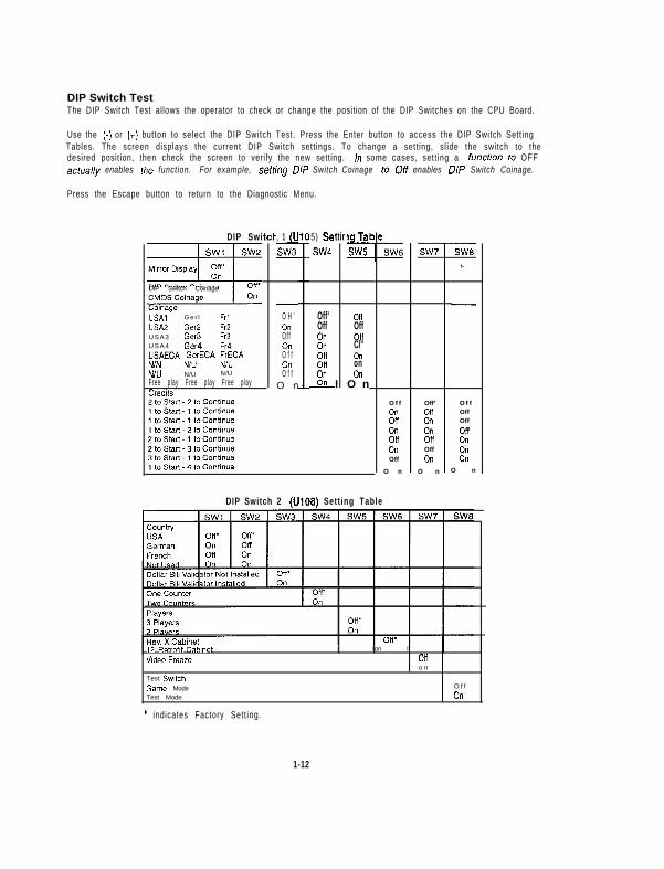
DIP Switch TestThe DIP Switch Test allows the operator to check or change the position of the DIP Switches on the CPU Board.
Use the (-) or (+) button to select the DIP Switch Test. Press the Enter button to access the DIP Switch Sett ingTables. The screen displays the current DIP Switch sett ings. To change a sett ing, sl ide the switch to thedesired posit ion, then check the screen to verify the new setting. In some cases, sett ing a funcfion to OFFacfua//y enables fhe function. For example, seffing DIP Switch Coinage to Off enables DIP Switch Coinage.
Press the Escape button to return to the Diagnostic Menu.
DIP Swi
DIP Switch Coinage
USA1 G e r l FrlUSA2 GNP FQ
, 1 (U-SW3
USA3 GM3 Fr3
USA4 GW4 Fr4“SAECA GerECA FrECA
NIN N/U N/U
N/U N/U N/U
Free p lay Free p lay Free p layCredits
-
O H ’OnO f fOnO f f0”O f f
O n
5) Sei
SW4
Off’OffOnOil0”Oflon
On
ttir
I
19 Ta-p&
0”OffOffCl”OnonOn
O n
DIP Switch 2 (U108) Sett ing Table
OffOnOff0”08OnOff
O n
Off’Off0”0”OfiOffOtl
O n
OffOffOffOffOnOnOn
O n
T2 Retrofit Cabinet
“ldeo Freeze
Test Switch
Game ModeTest Mode
* indicates Factory Sett ing.
I Ion I
Oflo n
O f f
On
1-12
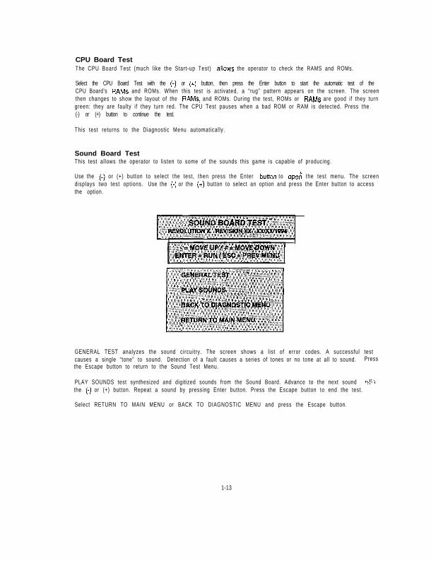
CPU Board TestThe CPU Board Test (much l ike the Start-up Test) aImlows the operator to check the RAMS and ROMs.
Select the CPU Board Test with the (-1 or (+) button, then press the Enter button to start the automatic test of theCPU Board’s RAMS and ROMs. When this test is activated, a “rug” pattern appears on the screen. The screenthen changes to show the layout of the RAMS, and ROMs. During the test, ROMs or RAMS are good i f they turngreen: they are faulty if they turn red. The CPU Test pauses when a bad ROM or RAM is detected. Press the(-) or (+) button to continue the test.
This test returns to the Diagnostic Menu automatical ly.
Sound Board TestThis test al lows the operator to l isten to some of the sounds this game is capable of producing.
Use the (-) or (+) button to select the test, then press the Enter bunon to oper? the test menu. The screendisplays two test options. Use the (-) or the (+) button to select an option and press the Enter button to accessthe option.
GENERAL TEST analyzes the sound circuitry. The screen shows a l ist of error codes. A successful testcauses a single “tone” to sound. Detection of a fault causes a series of tones or no tone at all to sound. Pressthe Escape button to return to the Sound Test Menu.
PLAY SOUNDS test synthesized and digitized sounds from the Sound Board. Advance to the next sound “!:‘lthe (-) or (+) button. Repeat a sound by pressing Enter button. Press the Escape button to end the test.
Select RETURN TO MAIN MENU or BACK TO DIAGNOSTIC MENU and press the Escape button.
1-13
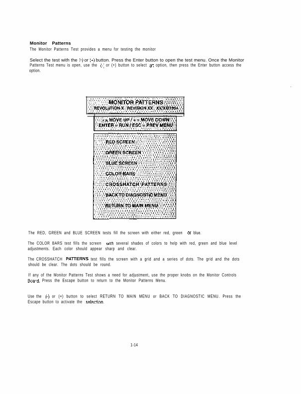
Monitor PatternsThe Monitor Patterns Test provides a menu for testing the monitor
Select the test with the (-) or (t) button. Press the Enter button to open the test menu. Once the MonitorPatterns Test menu is open, use the (-1 or (+) button to select ah option, then press the Enter button access theoption.
The RED, GREEN and BLUE SCREEN tests fi l l the screen with either red, green 01 blue.
The COLOR BARS test f i l ls the screen with several shades of colors to help with red, green and blue leveladjustments. Each color should appear sharp and clear.
The CROSSHATCH PAl7ERNS test f i l ls the screen with a grid and a series of dots. The grid and the dotsshould be clear. The dots should be round.
If any of the Monitor Patterns Test shows a need for adjustment, use the proper knobs on the Monitor ControlsBoard. Press the Escape button to return to the Monitor Patterns Menu.
Use the (-) or (+) button to select RETURN TO MAIN MENU or BACK TO DIAGNOSTIC MENU. Press theEscape button to activate the SelectIon.
1-14
Driver Board TestThis test provides the operator with a way to test the gun coils and the gun LEDs. Press the (-) or (c) but ton toselect the Driver Board Test. Press the Enter button to begin the test.
The test cycles through and pulses the gun coils and the gun LEDs. As each device is activated the name isdisplayed on the screen.
Press the Escape button or the Bomb button to return to the Diagnostic Test.
Burn-in TestThe Burn-in Test continually repeats the CPU Board Test. Use this test to find intermittent CPU Board prob-lems.
Press the (-) or (+) button to select the test, then press the Enter to begin tt?e test. When the Burn-in Testdetects an error the test stops and an error message is displayed on the screen.
The Audit Table specifies the number of Burn-in cycles that have been successfully completed.
To exit this test, switch the game off, then on again.
1 - 1 5

COIN BOOKKEEPINGUse the (-) or (+) button to select the Coin Bookkeeping Menu. then press the Enter button to open the menu.
The Coin BookkeepIng Table records th, 10 rain box totals and the game play counters.
To ex i t Coin Bookkeeping. use the (-) or (+) button to select RETIJRN TO MAIN MENU, then press the Escapebutton.
1 - 1 6

GAME AUDITSUse the (-) or (+) button to select the Game Audits Mew then press the Enter button to open it. Page throughthe avaIlable audits by select ing NEXT AUDIT PAGE or PREVIOUS AUDIT PAGE. Select RETURN TO MAINMENU and press the Escape button to exit Game Audits.
NOTEGame audits cannot be set. They can only be cleared.
PAGE ONE OF AUDIT TABLE
PAGE TWO OF AUDIT TABLE
l-17

Game Audits continued...
PAGE FOUR OF AUDIT TABLE
1-18
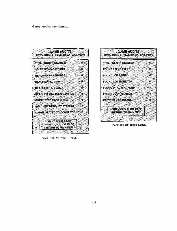
Game Audits continued...
PAGE FIVE OF AUDIT TABLE
1-19

GAME ADJUSTMENTSThie Game Adjustments al low the operator to customize the game
To select the Game Adjustments Menu press the (-1 or (+) button, then press the Enter button to open the menu.
Thle Game Adjustments Menu otters several options. Each option has several choices. Press the (-) or (+)button to select an option, then press the Enter button to open the option. The next menu screen provides asetting choice. Press the (+) button to increase the setting value and press the (-) button to decrease the settingvalue. When the desired value is reached, press the Enter button to lock it in.
To exit the Adjustments Menu, use the (-) or (+) button to select RETURN TO MAIN MENU, then press theEscape button.
Game adjusrmenfs are exphed in more detail on fhe following page.Adjustment values set by DIP SWITCH, override adjustment values set by the m&-w system.

Game Adjustments
Standard PricingStandard pricing allow the operator to choose any of the “standard” selections from the Standard Pricing Table.See page l-23.
Modify the sett ing value with the (-) or (+) button. Press the Enter button to lock in the new value and return tothe Adjustments Menu.
Custom PricingCustom pricing allows the operator to install pricnng other than that of the Standard Pricing Table. Custompricing also al lows the operator to select the maximum amount of credits per game, the amount of creditsrequired to start a game, and the amount of credits required to continue a game. This option is being adjustedfrom the DIP Switch sett ings. See page l-24.
Modify the sett ing value with the (-) or (+) button. Press the Enter button to loch” a new value and return to theAdjustment Menu.
Free P l a yThis option selects free play. The sett ing choices for this adjustment are:
- N o- Yes- Factory Set t ing: N o
Game Diff icultyThis option determines the dif f iculty level of the game play. The sett ing choices for this adjustment are:
- Easiest Sett ing: E a s y- Hardest Sett ing: H a r d- Factory Set t ing: M e d i u m
Energy Per PlayThe amount of energy a player receives each t ime he starts or continues a game. The sett ing range is:
- Maximum Set t ing: 2 0 0- Min imum Set t ing: 5- Factory Set t ing: 1 5 0
CDS Per PlayThe number of CDS a player receives each t ime he starts or continues a game. The sett ing range is:
- Maximum Set t ing: 9 9- Min imum Set t ing: 1 0- Factory Set t ing: 2 5
Minimum Time Per PlayThe minimum time, in seconds, the player is guaranteed to receive each play. The sett ing range is:
- Maximum Set t ing: 3 0 0- Min imum Set t ing: 5- Factory Set t ing: 7 5
Violence LevelThis controls the level of graphic violence. The setting choices are:
- High = Blood is red.- Medium = All blood is green.- low = No blood displayed.- Factory Set t ing: High
l-21
Game Adjustments continued...
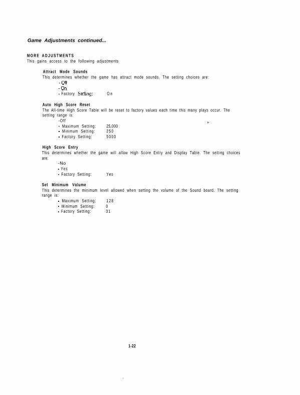
M O R E A D J U S T M E N T SThis gains access to the fol lowing adjustments
Attract Mode SoundsThis determines whether the game has attract mode sounds. The sett ing choices are:
-Off-On- Factory Settmg: O n
Auto High Score ResetThe All-t ime High Score Table wil l be reset to factory values each t ime this many plays occur. Thesett ing range is:
-O f f i- Maximum Set t ing: 25,000- Min imum Set t ing: 2 5 0- Factory Set t ing: 5 0 0 0
High Score EntryThis determines whether the game wil l al low High Score Entry and Display Table. The sett ing choicesare:
-No- Yes- Factory Set t ing: Yes
Set Minimum VolumeThis determines the minimum level al lowed when sett ing the volume of the Sound board. The sett ingrange is:
- Maximum Set t ing: 1 2 8- Min imum Set t ing: 0- Factory Set t ing: 3 1
1-22

U K 1UK2UK Em!UK mc wiccu
STANDARD PRICING TABLE
(1)
(2)
63)
(4)
(5)
(fi)
(i’)
F’)
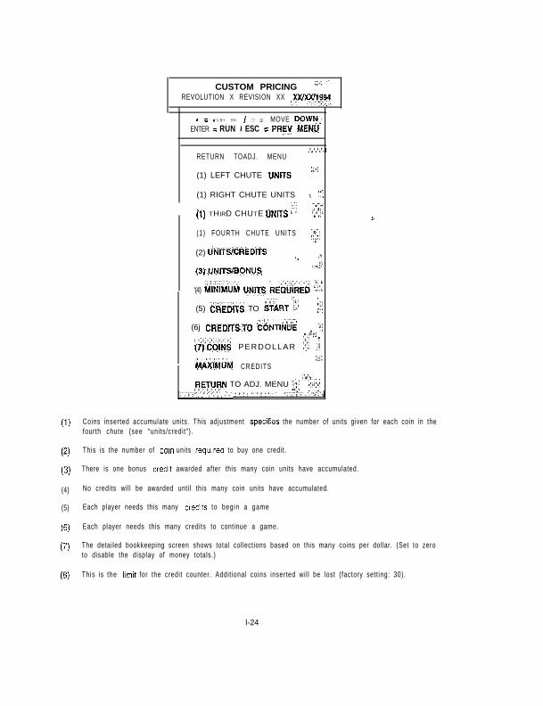
CUSTOM PRICING “‘.’ ”REVOLUTION X REVISION XX ,XWXXff~”
- = MOVE UP f + q MOVE DOWl-4~.ENTER = RUN i ESC = PREY #&ENU
RETURN TOADJ. MENU
(1) LEFT CHUTE UNlTS “?’
(1) RIGHT CHUTE UNITS . , ‘.f.
(1) THIRD CHUTE UNITS 1,” ,,I’,.,~
(1) FOURTH CHUTE UNITS ,:$j.
(2) UNlTS/CREDlTi : y, , L.i_:_,,.
(3)~NlTSBONUS
‘(4) kilillilUM UNlTs REQLilREd ‘?_.. :
(5) CREdlTS TO START (:: j :::f
(6j CREDITSTO C&TIN& ,_ i:i.,l,,
(7)CiINS PERDOLLAR ::’ : : :
MAifM,UM CREDITSi.L
RETUFN TO ADJ. MENU “‘;,.::,
~-?’
Coins inserted accumulate units. This adjustment specifies the number of units given for each coin in thefourth chute (see “units/credit”).
This is the number of coin units required to buy one credit.
There is one bonus credit awarded after this many coin units have accumulated.
No credits will be awarded until this many coin units have accumulated.
Each player needs this many credits to begin a game
Each player needs this many credits to continue a game.
The detailed bookkeeping screen shows total collections based on this many coins per dollar. (Set to zeroto disable the display of money totals.)
This is the limit for the credit counter. Addit ional coins inserted wil l be lost (factory sett ing: 30).
l-24

UTILITIESThe Uti l i t ies Menu allows the operator to clear the game’s bookkeeping memory and to install a custom mes-sage.
To select the Uti l i t ies Menu press the (-) or (c) button, then press the Enter button
Press the player (-) or (c) button to select a uti l i ty. Press the Enter button to activate the selection, A dialoguebox appears and the operator can choose to reset the util ity. For example:
I-
I CLEAR CREDITS?ARE YOU SURE? I
Press the (-) or (+) button to choose a setting value. Press the Enter button to lock in the new setting value.
To exit the Uti l i t ies Menu press the (-) or (c) button to select RETURN TO MAIN MENU, then press the Escapebutton.
1 - 2 5

CALIBRATE GUNSThe calibrate Guns option allows the operator to align the guns
Check gun calibration when the game is received. The gun assemblies are calibrated from the factow How-ever; guns mighf of been jarred during shipping and may need to be re-calibrated.
If you change boards or replace ROMs, RAMS or the battery. you must re-calibrate the guns. Guns do not
operate unless rhey are calibrated.
Pres,s the (-) or (+) button to select Calibrate Guns. Press the Enter button to access the option. The screenshows the operator two targets to aim and shoot at. The targets are located at the top left and bottom right ofthe screen. Calibrate the left gun f irst, then the r ight gun.
When the guns are calibrated correctly the message, - ‘*Calibration Successful**-, appeals on the screen.The data is stored in the CMOS RAM and the game automatically returns to the Main Menu.
If the gun calibration is not successful, the following message appears on the screen:-“CMOS RAM ERROR”-
Unable to write cal ibration values.Guns are not al igned.
Press any button to continue.Begin again to calibrate the guns. If you make a mistake, press the Escape but ton to abort the procedure andstart over. The screen returns to the Main Menu automatically.
l-26
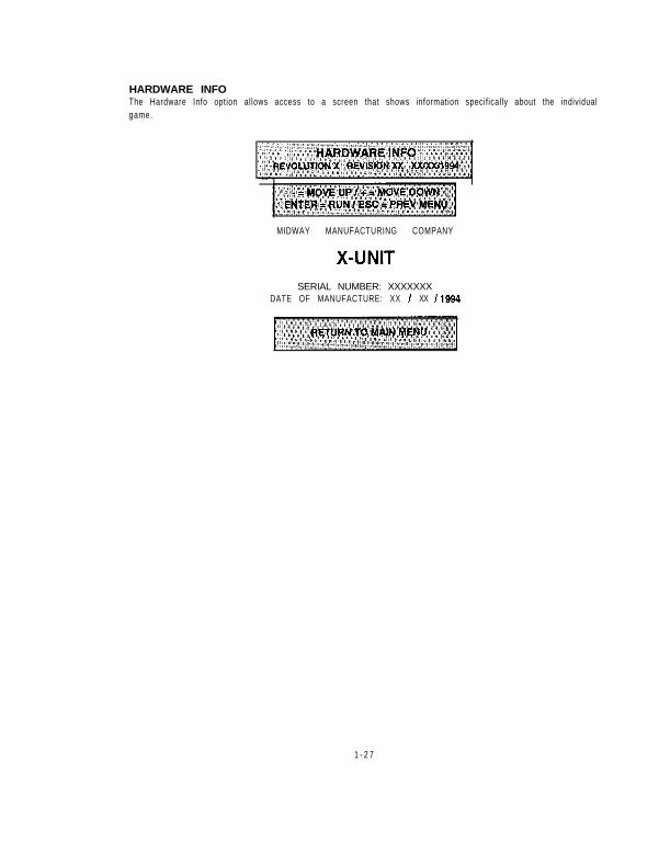
HARDWARE INFOThe Hardware Info option allows access to a screen that shows information specifically about the individualgame.
MIDWAY MANUFACTURING COMPANY
SERIAL NUMBER: XXXXXXXDATE OF MANUFACTURE: XX I XX I1994
1 - 2 7

ADJUST VOLUMEThe Adjust Volume feature allows the operator to determine the sound and music level of the game,
Press the (+) button to raise the volume level of the game and the (-) to lower the volume level. The currentvol(Jme level is shown with a red line. Press the Escape button to return to the Main Menu.
VOLUME LEVEL
Lowest I I I I ~ I I ! ! I I I ~ I I Highest
l-28

TROUBLESHOOTING
PROBLEMNo picture or distorted picture.
Turn game On and nothing happens
No sound.
No general illumination.
Press start button and nothinghappens.
No credit given for number of coinsinserted.
Too many credits for number ofcoins inserted.
Game stay in test mode.
POSSIBLE SOLUTIONCheck for faulty video board or monitor. Check for disconnectedvideo signal cable.
Check line fuse. Check for +5Vdc at pins C, D, 3 and 4 of theJAMMA connector.
Check the speaker and the speaker connection to pin L and 10 on theJAMMA connector. Checkvolume control sett ing. Check for +12Vdc atpins F and 6 on the JAMMA connector. Check interboard wiring fromCPU board to sound board. Also, check the fuse on the sound board.
Check the iA, S.B. fuse in the A.C. power pack assembly.
Check for open wires between the button and the CPU board. Check forcontamination on CPU board pins or the Start button switch blade con-tacts Check for proper ground.
Check DIP switch coin settings. Check for contamination on the coinswitch contacts. Check for an open wire between Coin Switch 1 and pin16 on the JAMMA connector or Coin Switch 2 and pin T of the JAMMAconnector.
Check the game pricing sett ings. Check for a short between pins T & 16on the JAMMA connector.
Check that the switch #6 of DIP switch bank #2 is set to off.
1-29

NOTES
l-30

REVOLUTION X
S E C T I O Ntwo
c
Parts
2-1
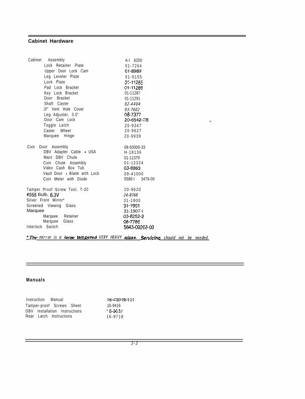
Cabinet Hardware
Cabinet Assembly A-l 6200Lock Retainer Plate 0 1 - 7 2 6 4Upper Door Lock Cam 01-8989Leg Leveler Plate 0 1 - 9 1 5 5Lock Plate 01-11285Pad Lock Bracket 01-11286Key Lock Bracket 01-11287Door Bracket 01-11291Shaft Caster 0 2 - 4 4 0 42 0 ” Vent Hole Cover 0 3 - 7 6 0 2Leg Adjuster, 3.0” 08-7377Door Cam Lock 20-6542-TBToggle Latch 2 0 - 9 3 4 7Caster Wheel 2 0 - 9 6 2 7Marquee Hinge 2 0 - 9 9 3 9
Coin Door Assembly 09-50000-33DBV Adapter Cable - USA H - 1 8 1 3 6Mars DBV Chute 01-11379Coin Chute Assembly 0 1 - 1 2 3 2 4Video Cash Box Tub 03-8863Vault Door - Blank with Lock 0 9 - 4 1 0 0 0Coin Meter with Diode 5580-l 3476-00
Tamper Proof Screw Tool , T-20 2 0 - 9 6 2 0#555 Bulb, 6.3V 24-8768Silver Front Mirror* 3 1 - 1 9 0 0Screened Viewing Glass 31-1901Marquee 31-1907-l
Marquee Retainer 03-8252-2Marquee Glass 08-7786
Inter lock Switch 5643-09268-00
2 m i r r o r i s a larae ternowed V E R Y H E A V Y a/ass. Servicina s h o u l d n o t b e n e e d e d .
Manuals
Instruction Manual 16-40019-101Tamper-proof Screws Sheet 16-9416DBV Installation Instructions 16-9637Rear Latch Instructions 1 6 - 9 7 1 8
2 - 2
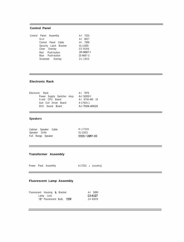
Control Panel
Control Panel AssemblyG u nControl Panel CableSecurity Latch BracketClear OverlayRed Push-buttonBlue Push-buttonScreened Overlay
A-l 7033A-l 8027H-l 799901-119550 3 - 9 0 8 620-9687-l20-9687-33 1 - 1 9 0 3
Electronic Rack
Electronic Rack A-l 7876Power Supply Switcher Assy A-l 5202-lX-unit CPU Board A-l 6744-400 19Gun Coil Driver Board A-17024.1DCS Sound Board A-l 7026-40019
Speakers
Cabinet Speaker Cable H - 1 7 0 3 5Speaker Grille 01-12421Full Range Speaker 5555-13961-00
Transformer Assembly
Power Pack Assembly A-17031 - (country)
Fluorescent Lamp Assembly
Fluorescent Housing & BracketLamp Lock18” Fluorescent Bulb, 15W
A-l 589003-83272 4 - 8 8 0 9

Cables
Line Voltage Cable Assembly A- 17877-2Dixie-Mars Interconnect Cable H - 1 7 0 1 9Cabinet Speaker Cable H - 1 7 0 3 5Main Harness Cable H-17715.1Control Panel Cable H-l 7999DBV Adapter Cable - USA H - 1 6 1 3 620.pin Ribbon Cable 5795-10937-18
Monitor
Monitor Support Bracket, LeftMonitor Support Bracket, RightMonitor Bezel2ti” Monitor
A-l 4769A- 1477003-8497-25675-12787-05
2 - 4
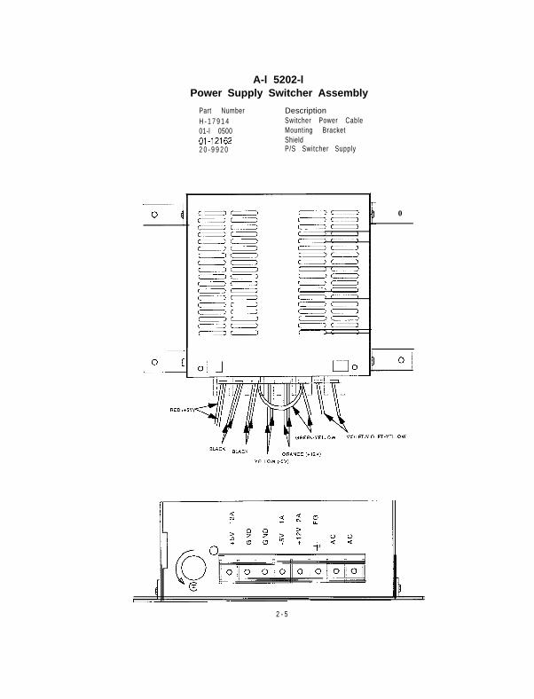
A-l 5202-lPower Supply Switcher Assembly
Part Number DescriptionH - 1 7 9 1 4 Switcher Power Cable01-l 0500 Mounting Bracket01-12162 Shield2 0 - 9 9 2 0 P/S Switcher Supply
0
2 - 5

A-16744-4001 9X-unit CPU Board Assembly
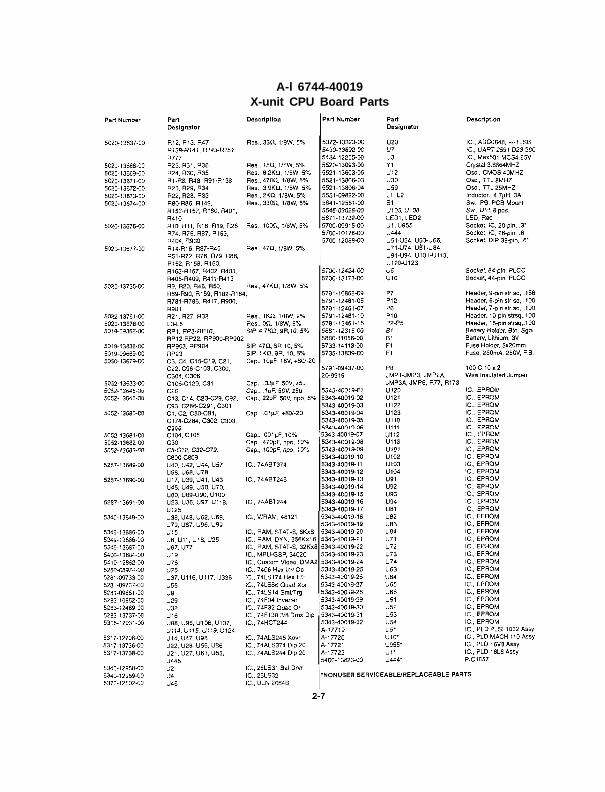
A-l 6744-40019X-unit CPU Board Parts
A-17026-4001 9Sound Board Assembly

A-l 7026-40019Sound Board Parts
2-9

A-l 7024.1Gun Coil Driver Board Assembly
: -
[-1;--
--
? ;IF
-7
-13-
- I---
J i _
i
2-10
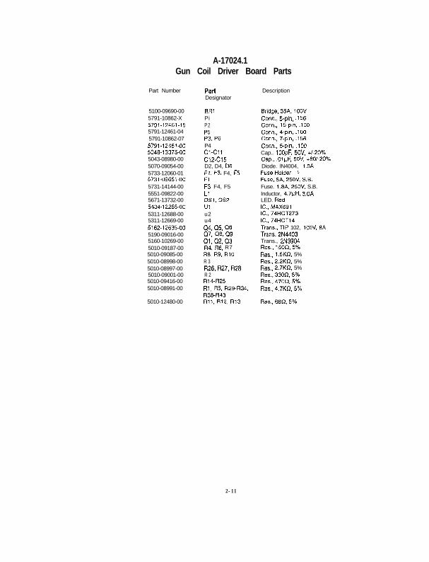
A-17024.1Gun Coil Driver Board Parts
Part Number
5100-09690-005791-10862-X5791-12461-155791-12461-045791-10862-075791-12461-005048-13375-005043-08980-005070-09054-005733-12060-015731-09651-005731-14144-005551-09822-005671-13732-005434-12255-005311-12688-005311-12669-005162-12635-005190-09016-005160-10269-005010-09187-005010-09085-005010-08998-005010-08997-005010-09001-005010-09416-005010-08991-00
5010-12480-00
PallDesignator
BRlPiP2P5P3,P6P4Cl-Cl1C12-Cl5D2, D4, 06Fi, F3. F4, F5FlF3, F4, F5LlDS1.052Uiu2u4Q4. 05. Q607. 00. Cl9ai.a2,Q3R4. R6. R7R8,R9,RlOR 3RZ6,R27,R28R 2R14-R25Rl, R5, R29-R34,R38-R43Rll,R12, RI3
Description
Bridge,35A,lOOVConn.,5-pin. ,156Corn, 15.pin,.100Corm., 4-pin..100Corm.. 7.oh.156Co& a-bin; .lWCap.. lOOpF, 5OV, +/-20%Cap...ol~F, 5OV, +80/-20%Diode. lN4004, l.OAFuseHolder sFuse.SA,250V,S.B.Fuse. 1.8A.25Ov, S.B.Inductor, 4.7#H, 3.OALED. RedIC.,MAX691IC.,74HCT273IC.,74HCT14Trans.,TIP 102, 100% 8ATrans,2N4403Trans., 2N3904Res..150n,5%Res.. 1.5KR, 5%Res.. 2.2KR, 5%Res.. 2.7KR, 5%Res..330R,5%Res..470R.5%Res.;4.7KR.5%
2-11

A-l 8027Gun Assembly

A-l 8027Gun Parts
Item Part Number Description
1 01-130262 01-130273 03.89864 03.89875 03.89896 03.89887 1 O-465
Base Housrng. LeftBase Housing. RtghtGun Housing. Molded LeftGun Housing. Molded RightBomb ButtonTriggerSpring. TriggerSpring. Bomb ButtonSwch. Bomb ButtonSwitch, TriggerLED Board AssemblyLED ExtensionTS, 8-32 x 318 PH.Trx-T: Typ23 Blk (10)MS, 8-32 x l-3/8 TPR Black (6)MS, IO-32 x 3/E FH Torx TP Black (6)MS, lo-32 x 5/E FH Torx TP Black (4)SMS, #8 x 518 #l Riser PH-T-PO TP Blk (2)Nut. 8-32 ESNA Black (6)
8 1 O-4669 A-18603i0 5647-12693-0611 A-1883412 03-9230-913 4008.01090-06B14 4008.01093-22815 4010.01148-06816 4010-01148-10817 4108.01092-10818 4408-01119-008
19 Gun Mechanism Partsa) AE-23-800-08bl 03-7067-5c l 23.6735d) 01-13028e) 23.6736fl lo-482
,i oz.5059h) 20-10105
i) 5014-12909-00I) 03-8528-lkl 20-10107
ml 20-10106n\ 03-9202Pi 20-101089) 03.92030 20-10109
Coil AssemblyTubina. Plasf~cBump& Plunger Rev X GunSolenoid BracketBumper, Recoil Pad Rev X GunSpring, CompressionPlungerBum& 314” DiameterPotentiometer 121Gear, Segmeni, j2DPGear, Segment, HublessGear. SpurspacerBumperDisk, Plastic WasherBearing, ,625 Bore (4)
2-13

NOTES
-
-
2-14
REVOLUTION X
S E C T I O Nthree
Wiring Diagramsand
Schematics
3-1

JAMMA CHART
1 Function 1 Wire Color Pin Pin ’ Wire Color 1 Function 1GroundGround+SVdc+SVdc-5Vdc--+12Vdc_
Black 1 A Black GroundBlack 2 B Black - G r o u n dR e d 3 -c R e d +5VdcR e d 4 D R e d +SVdcYellow 5 E Vellsw -5VdcOrange 6 F Oranqe +iPVdc
3-2

INTERBOARD WIRING DIAGRAM
CPU BOARD
SOUND BOARDA-1702640019
3-3
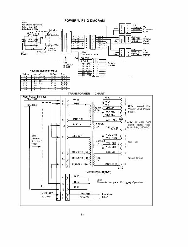
13 26
1% 312OV Isolated For
4 Monitor And Power5 SUPPlY6
-RED ;
IIIIIIII
See IVoltage lSelectionITable l-1
IIIIIIIIIII
TRANSFORMER CHART
’ 5.9V For Coin DaaLights. Note: Fuse
2 is IA S.B., 250VAC
I IU
XFMR 5610-13629-02
Shown As Jumpered Fo
36
Gun Coil45
7
Sound Board
9
r 12OV Operation.
I
3-4

I i
a
n


i r

I

T Y I I
-
-
r r

:... .:..,.

c

Y ” i
.


P
m
--
2
. . I,
r
I

i >
-

J
i

I- I

.
-I

--0 /.w I
1
ba? :
--o
- +
I II
I I 71 II
.
L.
I III


I!7
PI

t
1
1

-
1


r

IO
lo
4