terminator 2 - ohwow-arcade.com
TRANSCRIPT

Terminator 2

TABLE OF CONTENTS
=ewSection 1 Operation and Troubleshooting
.....................................................................................................................Set-up Procedure
l-2
Installation & InspectionLocation Requirements
............................................................. l-3.................................................................
Front Cabinet Assembly Diagraml-3
.................................................Rear Cabinet Assembly Diagram
1-4
SetiCing................................................... 1-5
...................................................................................................................Game Features
l-6
Starting-up ...................................................................................Player Controls
1-8.............................................................................
Control Panel Diagraml-8
..................................................................Game Operation
l-8
Control Switches..........................................................................Control Switch Location Diagram
l-9.................................................
Menu System Operation1-g
Operation.....................................................................................Main Menu
l-10..................................................................................
Diagnostic Testsl-10
........................................................................... l-1 1Switch Test........................................................................ l-11DIP Switch Test & Table .................................................... l-12CPU & Sound Tests ........................................................... 1-13Monitor Patterns ............................................................... l-14Bum-in Test......................................................................
Coin Bookkeepingl-15
........................................................................Game Audits
1-16................................................................................
Game Adjustments1-17
.......................................................................Standard Pricing Table
l-19.................................................................
Custom Pricing Tablel-22
...................................................................Utilities
l-23........................................................................................................
Calibrate Gunsl-24
........................................................................................Troubleshooting
l-25...................................................................................................... l-26
Section 2 Parts InformationCabinet, Speaker, Manuals, & Monitor. . . . . . . . . . . . . . . . . . . . . . . . . . . . . . . . . . . . . . . . . . . . . . . . . . . . .PC Boards, Transformer & Lamp Assy. & Control Panel
2 - 2
Cables. . . . . . . . . . . . . . . . . . . . . . . . . . . . 2-3
. . . . . . . . . . . . . . . . . . . . . . . . . . . . . . . . . . . . . . . . . . . . . . . . . . . . . . . . . . . . . . . . . . . . . . . . . ..*.**.......................2-4Power Supply. . . . . . . . . . . . . . . . . . . . . . . . . . . . . . . . . . . . . . . . . . . . . . . . . . . . . . . . . . . . . . . . . . . . . . . . . . . . . . . . . . . . . . . . . . .CPU Board
2-5. . . . . . . . . . . . . . . . . . . . . . . . . . . . . . . . . . . . . . . . . . . . . . . . . . . . . . . . . . . . . . . . . . . . . . . . . . . . . . . . . . . . . . . . . . . . . . .2-6
Sound Board. . . . . . . . . . . . . . . . . . . . . . . . . . . . . . . . . . . . . . . . . . . . . . . . . . . . . . . . . . . . . . . . . . . . . . . . . . . . . . . . . . . . . . . . . . . .Coil Lamp Driver Board
2-8
Gun Assembly. . . . . . . . . . . . . . . . . . . . . . . . . . . . . . . . . . . . . . . . . . . . . . . . . . . . . . . . . . . . . . . . . . . . . . . . . . . . 2-10
. . . . . . . . . . . . . . . . . . . . . . . . . . . . . . . . . . . . . . . . . . . . . . . . . . . . . . . . . . . . . . . . . . . . . . . . . . . . . . . . . . . . . . . . . . 2-12Dual Flashlamp & LED Boards. . . . . . . . . . . . . . . . . . . . . . . . . . . . . . . . . . . . . . . . . . . . . . . . . . . . . . . . . . . . . . . . . 2-14
Section 3 Diagrams and SchematicsCPU Board............................................................................................... 3-2Dual Flashlamp & LED Boards ................................................................ .3-18Sound Board............................................................................................ 3-19Coil Lamp Driver Board ............................................................................ 3-23JAMMA Chart & Power Wiring Diagram ................................................... .3-26Cabinet Wiring & Main Harness Wiring .................................................... 3-27Control Panel Wiring................................................................................ 3-28
b Copyright 199 1 MIDWAY Manufacturing Company

Terminator 2
S E C T I
one0 N
I
Operation
l-l

Safety NoticesThe following safety instructions apply to all game operators and service person-nel. Specific warnings and cautions will be found throughout thismanual wherethey apply. We recommend that you read this page before preparing your gamefor play.
. . . . . . . . . . . . .,.,.,. . . ~~~~.~..~~....~~.~.~~~::~..‘.‘:‘:’:’:’:’:’:’:’:‘:‘:~:‘:‘:’:~:’:~:~:‘:~:~.~.~.:.:.~.:.:.........:.:.:.:.:.:.:.:.:.:.:.:.:.:.:.:............:.~ :.:.:.:.:.‘.:‘E’:‘:‘:‘:‘:‘:‘:” ‘,‘,i!...:...:.::: ~t,~.~,~,~,))~.~,~.~.~.~.~,~,~,~,~,~,~,~,~~.~.rr,,,,,,,,,,,.,‘,‘,‘....................,.,.,, ,.,., ,.,.............A :.:.:+:.: .,.,.,.,.,.,.,.,.,‘,‘,‘,‘,..‘..,.,.,....~,~,~,~,~,,,,.,‘VA’.... ‘.‘.‘.‘.‘.‘.:.:...:.:.: .,... :.: .,.,.,.,.,.., ,,, . .“““““‘:‘:‘:‘:‘:‘“..“.‘, “““:‘~‘~‘~‘~‘.‘.‘:t:~:~:~:~:~:~:~:~:~~:~:~:~...~.:..... ‘.‘.‘.‘.‘.‘.‘.‘.‘.‘.‘.‘.‘.‘.‘.‘.’.’.: . . . . . . ..X..% : .,...,...,.....,......i.,.......... ,,, ,,.,.,,,.,.,.,.,.,.,.,.,.,...,.,.,.,~,..~,~ :::,,: :“““““““““~~~~““““““‘~““““““...‘~~~’..’...’.:.:.:............................~.~.~...~.~.:.~.~ . . . . . ::.:.:.:.:.:.:.:.:.:.:.:.:.:.:.:.:.:.:.:.:c:“““““::1:“!‘:‘:‘c’:::.:::::::::::::”.”.’.””””””““““““.‘.‘..... .~...~...~......................,.....,~.,,,.,.,,,,,,,,,,,,,,,,,,,,,,,,,,,,,,,,,,,,,,,,,,,,,,,,,,,,,,~,,,,,,,,,,,,,,,,,,,__L,,,,,,,,,,,,i_,,,,,,,,,,,“““““““““““‘““::::::::::::::::::””~”’~~~~~~””””“““““~‘.‘.’.~.’ ..“““““““““.....,.........................,......,,...,.,,,,,,,,,,,,,,,,,,,,,,,,,,,,,,,~,,,,,,,,,,,,::,,,,,,,,,,,,,,,,,,,,,‘.‘.‘.‘................ i . . . . . . . ..:,: ,.:., .,.,.,,,, ,,, ,,, ,,., ..:.:, ~.~.:,:.:.:,~::::,:,:,:,:,:,:,:,:,:,:,:,:,:,:.:,‘.‘.‘,‘:‘:’:’:::::::::::::::,:,:,:,.,:““““‘““““‘i”“.“..........“..........:.:.:.:.:.:.:.:.:.:.:.:.:.:.::::.:.:.:.:.: ‘..“““““.,.....,.,....~.,.,,~,,,,,,,,,,,,,,,,,,,,,~,~,,,,,,,,,,,,,,,,,,,,,,,,,,~,~,~,~,,,,,,,,,,,,,,,,~,,,,~,,,~,,,,,,,,,,,,,,,,,,,,,,,,,,,,~,,,,~~‘,,.,,..._“““““““““““..‘..................................................’ .““““““““.5.“‘.““““““““‘.““‘...““”””””””””” 7,: ‘. “““““““““““““‘.‘.‘.‘.‘.
.,:::,,,; ,:,:,,,,,,,,,,,,,,,,,,,,,,,..,,..:,,,,,,“““‘~‘~‘~~~~~~~~:::~~:~.‘.‘...‘..........,...,.,.,.....,...,,,....................... :..::: .,,,,,,,,,,,,,,,,,,,,,, (, ,, ,,,i,,,,,,,,, ,.,.,,.,.,.,.,.,.,’ j ,,,,,,:,,,,,,,,_,,,,,,,,,.‘.‘.‘.‘.:.:.:.:.::::::::::::.:::.:.:.:.:.:.:.:.:.:.:.:.:.:.:.:.:.:.::,:.:,: .,...,.,.,.,.,.,...,...,...............,.,.,:,:.: ,., :,,:, ;, . ,, .A.. . . :,:,:,:,,,,,,,,,,,,,,,,,,,,,,,,,,,,,,:,:,:,:::,::,:,: : : : : : : : : : : : : : : : : :,,, .>,.: VA....‘.:.‘.:s..‘.‘.:.:.:.:::: “‘.“““““““““’ “‘.“““““““““““” “‘.‘.‘.‘.‘.‘.‘.‘.‘.‘.‘.‘.‘.‘.‘.‘.’.’.’.’.’...I........:.:.:.:.:.:.:.:.:.:.:.:.:.:.:.:.:.:.~~..:.: ~..,~.~.~.:,:,,,,.,.,.,,,,,,,,,,,,,~,~,~,.,~,.,~~....~...,.,.,,,,,,,,,,,,~~~~,,~~,~,,,,,,,,,,,,,,,,,,,,~~~~~~~~~.~:: ::::::::::>:.:.:.: . ..A . . . .A........., > . . . . . . . . . . . . . . . . . . . . . . . . . . . . . . . . . . . . . . . . . . . .v.... . . . . . . . . . . .. . . . .‘,‘,‘,‘,‘,‘,‘,:,:,., )[ ~~~~~~~~~~~~~“~,~~.~ ,,,,..,.. . ,. . . . . . ,,) . . . . :.:.:,:.:,:,:,:,:,:.:,:.:.:.:.:.:.:.:.:.:.:.~:.:.:.:.:.: . . . . +:.:..:;.:.‘.‘:;;::“‘::~::::~ %V.‘. v ‘...‘.‘.‘.‘.‘.” ‘.‘.‘.‘.‘.‘.‘.‘.’
. . . . . . . . . . . . . . . . . . . . . . . . . . . . . . . . . . . . . . . . . . . . . . . . . . . . . . . . . . . . . . . . I,.....,. . . ..~...........~~ ; ““‘:::::::::::::::::.:‘.....,.:.:.:.:.:.:.:.:.:.:. :...:.. y.“““‘.,.,.,.,.: . . . . ..‘...‘.‘,‘,‘,‘,‘,‘,.........,....~. . . . . . . . . .._.._._....... .,,,,,,,,,, ,,....,,.,,,,,,,,,,,,,,,,~,,,,,,,~,~~~~~~~,~~,~~~ ,,,,.,,,.,,,,.,...........,,,,,,::::,:,.,.., ;;; ,,,,,,,_.......,.ll.,,,,,,,,,,,,.........‘7.‘. .W.~~ * ,.,.,, _ ,,:, ~::~~~:~.~.~.~.~.~.~ . . . . . . .
AC POWER CONNECTION. Before connecting the game to the AC powersource, verify that the “line voltage selection chart” jumper wires areinstalled correctly for the line voltage in your area. For details, refer toSection 3.
PROPERLY GROUND THE GAME. To avoid electrical shocks, do not plugin the game until it has been inspected and properly grounded. MIDWAYgames should only be plugged into a grounded 3-wire outlet. Shocks willalso result, if the control panel is not properly grounded! After servicingany parts on the panel, assure that the ground wires are secure. Only thenshould you lock up the game.
DISCONNECT POWER DURING REPAIRS. To avoid electrical shock, dis-connect the game from the AC power source before removing or repairingany part of the game.
USE THE PROPER FUSE. To avoid electrical shock, use the replacementfuse which is specified in the parts list for this game. The replacement fusemust match the original fuse in fuse type, voltage rating, and currentrating.
MONITOR PRECAUTIONS. When removing or repairing the monitor,extra precautions must be taken to avoid electrical shock because highvoltages may exist within the monitor circuitry and cathode ray tube (CRT)even after power has been disconnected. Do not touch internal parts ofthe monitor with your hands or metal objects! Always discharge the CFZI’by the following method: Attach one end of a large, well-insulated, 20-kVjumper to ground. Momentarily touch the free end of thegroundedjumperto the anode by sliding it under the anode cap. Wait two minutes anddischarge the anode again.
HANDLE FLUORESCENT TUBE AND CRT WITH CARE. If you drop afluorescent tube or CRT and it breaks, it will implode! Shattered glass canfly eight feet or more from the implosion.
ATTENTION !PROPERLYAITACHALL CONNECTORS. Make sure that the connectorson each printed circuit board (PCB) are properhy connected. If they do notslip on easily, do notforce ihem. A reversed connector may damage yourgame and void the warranty. All connectors are keyed to_/it specficpinson each board.
l-2

Setup Procedure
INSPECTION & INSTALLATION
1. Remove all items from shipping container and setthem aside. Inspect the exterior of the cabinet for anydamage. Remove the shipping cleats from the bottom ofthe cabinet.
2. Remove keys from the taped coinretum slot. Unlockand open the coin and cash box doors. (Leg levelers and spareparts are stored in the cash box.)
3. Tilt or lay the cabinet down. Locate the four threadedholes on the bottom of the cabinet (one in each comer), andinstall one leg leveler (with its hex nut) in each hole.
4. Stand the cabinet upright and make certain that it isin a stable position. Level the cabinet.
5. Remove the rear door of the cabinet. Inspect theinterior for any signs of damage. Check all major assembliesto assure that they are mounted securely.
6. Refer to the game’s Cabinet Wiring Diagram (Section3), and check to see that all cable connectors are correctlysecured. DO NOT FORCE CONNECTORS. Watch for dam-aged connectors and avoid making reversed connections.
7. Determine the value of your line voltage with a meter.Then, check the power input wires to the main power supplytransformer on your game to be sure they are connected totaps which correspond to your local line voltage value. Ifnecessary, reconnect the power input wires to the transformerin accordance with the Tranformer Chart in Section 3.
8. Lay the line cord (connected to the Power Chassis) inthe slot along the bottom edge of the rear cabinet door.Replace the rear cabinet door and screw (lock) it securely.Close and lock the front coin and cash box doors.
9. Plug the line cord into a grounded (3-terminal) AC walloutlet.
10. Switch On the game, using the On/Off switch locatedon the upper left rear of the cabinet, to verify proper operation.
11. If the following message appears on the screen whenthe game is turned On, the guns must be calibrated.
**CMOS RAM Error**Unable to read gun calibration values.
Do not attempt to calibrate by opening the guns and adjustingthe potentiometersmanually. Gun calibration instruction areon page l-25 of this manual.
l-3
Game LocationRequirements
PowerDomestic 115V @ 60 HzForeign 230V @ 50 Hz
Temp.32” F to 100” F(O” C to 38” C)
HumidityNot to exceed 95% relative.
Heiaht of aameApx. 74”
Weiaht of aameApx. 300 pounds
Check Gun calibration whenyou receive your game. Gunsmight of been jarred duringshipping and need to be re-calibrated.
The Gun Assemblies are cali-brated from the factory. How-ever, if you change boards orreplace ROMs, RAMS, or thebattery, you must recalibratethe guns. Guns do not operateunless they are calibrated.

Cabinet Assembly
2 0 - 9 6 8 7 - 3Player 1 Start
31-1632-4ooo9
---i-l- 31-1633-40009__ _._.._.-- Screened Glass
20-9687- 1Player 2 Start Button /’
A- 14764Control Panel Assembly
/
i
/
A- 14794- 1Chassis Panel Assembly
/
Front View
l-4

Cabinet Assembly
31-1643Screened Mirror _
03-8497- 1 _ _ _Bezel
5675- 12787-00 -Monitor
A- 14732-40009Sound Board- -
A- 14205Power Supply,
B- 13086Casters ._
5640- 10932-00On/Off Switch
A- 13340Line Cord --)m
.
A-14415Gun Assembly
A-14818-40009-- CPU Board
A-14915,Coil Lamp Driver Board
5610-12945-00-. Transformer
Rear View
l-5

Servicing
To remove the control panel forbench servicing, reach throughthe coin door opening and re-lease the latches located on thesides of the control panel. Becareful not to reach straight backthrough the coin door opening asyou might damage the MonitorControl Board. Carefully, tilt thecontrol panel forward until theguns rest against the viewingglass. Disconnect the cables andthe ground strap. Lift the controlpanel out of the game cabinet.
The monitor DOES NOT containan isolation transformer in itschassis (it is mounted instead inthe Power Chassis Assembly lo-cated on the floor of the cabinet).When servicing the monitor on atest bench, YOU MUST ISOLATETHE MONZTOR FROM THE LINEVOLTAGE WITH AN ISOLATIONTRANSFORMER.
While removing the four bolts,fily support the monitor fromthefront ofthe CRTs0 that it willnot slip.
Servicing the Control PanelSwitch Off power to the game. The control panel is heldin place by four latches (located inside the cabinet, on theleft and right sides of the control panel) which provideconstant pressure on the strikes. The latches can bereached through the coin door opening. To release thelatches, lift the latch handle and unhook the wire fasten-ers. Carefully, use the guns to lift the control panel.Carefully, tilt the control panel forward until the gunsrest against the viewing glass. THIS CONTROL PANELDOES NOT HAVE A SUPPORT BRACKET. To reinstall thecontrol panel, check for proper cable connections, in-cluding the ground strap, and use the guns to lower it intoposition, avoiding pinched wires. Reclamp the latches.
Servicing the Chassis PanelSwitch Offpower to the game and open the coin door. Thechassis panel is accessible through the front door. Thefront door is held in place by the same type of latch thatholds the control panel. The latch, located at the top ofthe front door, can be reached through the coin door. Liftthe latch handle and unhook the wire fastner. Push thefront door from the inside of the cabinet and remove it.Use the hand hole to slide the chassis panel forward.
Removal of Viewing GlassSwitch Off power to the game, and open the control panel.Carefully lift the glass from its bottom groove and lift itclear of the cabinet.
Removal of Monitor BezelSwitch Off power to the game. Remove T- 15 torx screwsholding the rear door. Remove the rear door. Remove thefour screws holding the bezel. Lift the bezel off themonitor.
Monitor ReplacementWe recommend that you read the WARNINGS section thor-oughly before beginning this procedure.Switch Off power to the game. Remove the rear door, theviewing glass and the monitor bezel. Completely discon-nect the monitor from all of its cabling, including itschassis ground strap. Remove the four bolts securing themonitor’s mounting flanges to its mounting panel. Pullthe monitor carefully from the back of the cabinet.
l-6

Flashlamp ReplacementSwitch Off power to the game. Open the control panel inorder to remove the viewing glass: then, replace thecontrol panel. Open the rear door. Remove the twoscrews holding the mirror retainer. Carefully, pull themirror retainer out of the cabinet. The flashlamp boardsare accessible from the front of the cabinet once themirror is out. WARNING
If you drop a fluorescent tube
pemnval of the Marauee and it break-_--__ .I _ ---we -‘---L-_ _
Switch Off power to the game. Remove the five #8 hexUse care in t
S~.~~..~~.!~.!~~,~.~~~~.~~~.~washer head screws in the black plastic strip on top of the f . . . . . . . ..~...)12’cabinet. Remove the strip and carefully lift the plastic
$&fl;&%;>.&.&@&j
marquee and the clear glass. Store the marquee and glasscarefully to prevent damage.
The fluorescent tube is now accessible for replacement.Grasp the tube, give it a quarter turn, and remove it fromits socket. Carefully place a new tube into the socket, andturn to reinstall.
Removal of the Fluorescent LightAssemblySwitch Off power to the game. Remove the marquee glass.Disconnect the fluorescent light assembly from its powercable. Remove the screws fastening the assembly to thecabinet and lift out the assembly.
Removal of the SpeakersSwitch Off power to the game. Remove the marquee. Thespeakers pull out from the front of the cabinet. Be sureto disconnect the cabling and remove the nuts on themounting bolts before attempting to pull the speakers outof their enclosure.
Volume Control, Test/Diagnostics Switch,and Service Credit SwitchOpen the coin door to locate the game’s volume controland Diagnostic switches on the small panel atop the cashbox cover. The Volume Control is the white knob on leftend of the panel. Turning the knob clockwise increasesthe volume. The upper right switch on the bracket is theTest/Diagnostics Switch that enablesactivating thegame’sMenu System. The lower right switch is the Service CreditSwitch, which allows adding credits to a game for servicetesting without affecting the game’s bookkeeping total.
l-7

When an error is detected duringWart_1173 TpCtC dame ctnrt-1173irrur L “y A”“L”, ~.A”” -I-- _ -rpauses. Press any Start Button tocontinue.
Game Features
STARTING UPSwitch On power to the game. A”rug” pattern appears on theCRT screen. When the “rug” pattern ends, the screen showsCHECKING SCRATCH RAMS, and then CHECKING ROMS.The next screen shows Terminator 2 REVISION LEVEL,CMOS TEST OK and the COIN SETTING. The game thenmoves to the Attract Mode.
Insert the desired amount of coins or tokens. Seiect whichplayer receives the credit by pressing the appropriate PlayerStart Button.
PLAYER CONTROLS
q Start ButtonEach player has two Start Buttons located on the leftand right sides of the guns. The Start Buttons allowone or two players to begin or continue play.
Each player has a gun. The guns allow the player toaim for and shoot at moving targets.
Each player has a Bomb Button located on the frontleft side of their gun. This button allows the player tofire bombs at targets.
q LEDs
Each player has two LEDs located on the top of theirgun. The Red LED indicates the player is targetedand being shot at. The Green LED indicates that theplayer is on target to shoot.
Control Panel
1-8
Game Operation
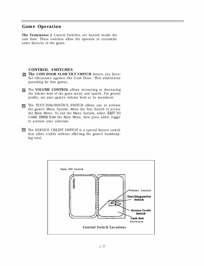
The Terminator 2 Control Switches are located inside thecoin door. These switches allow the operator to customizesome features of the game.
CONTROL SWITCHESThe COIN DOOR SLAM TILT SWITCH detects any force-ful vibrations against the Coin Door. This eliminatespounding for free games.
The VOLUME CONTROL allows increasing or decreasingthe volume level of the game music and speech. For greaterprofits, set your game’s volume level at its maximum.
The TEST/DIAGNOSTICS SWITCH allows you to activatethe game’s Menu System. Move the Test Switch to accessthe Main Menu. To exit the Menu System, select EXIT TOGAME OVER from the Main Menu, then press either triggerto activate your selection.
The SERVICE CREDIT SWITCH is a special feature switchthat allots credits without affecting the game’s bookkeep-ing total.
Slam Tilt Switch
Volume Control
Enclosure
Control Switch Locations
l-9

Menu System Operation
OPERATIONAll Game Audits, Adjustments, and Diagnostics are optionsof the Main Menu. Each option, in turn. has its own menu,listing several choices that you may act upon as desired.
Move the Test Switch (on the cashbox lid panel), or closeSwitch #8 of DIP Switch Bank #2, to activate the Main Menu(shown below). Game adjustments, bookkeeping, and diag-nostics are all accessible from this menu.
Press either Player 1 Start Button to move up the menu.Press either Player 2 Start Button to move down the menu.Notice that the options are highlighted in sequence. Presseither trigger to activate a highlighted option.Note: Only highlighted options can be activated.
DIAGNOSTIC TESTS
COIN BOOKKEEPING
GAME AUDITS
GAME ADJUSTMENT
UTILITIES
CALIBRATE GUNS
EXIT TO GAME OVER
Main Menu
l -10

DIAGNOSTIC TESTSTo enter the Diagnostic Tests from the Main Menu, press anyStart Button to select (highlight) the Diagnostic Test option,then, press either trigger to activate the option.
PI START= UP/P2 START=DOWNI *...-- a-- w---v -r-h X-rAti-llVlXl33 WFl’J3 -A.KKILiCir;K’
Diagnostic Menu
Switch TestThe Switch Test allows the operator to test the switches onthe control panel and the coin door.
During the Switch Test, the top of the screen is black and thebottom of the screen shows the coin door switches. Pressinga Start Button or trigger causes the name of the switchactivated to light on the top of the screen. Pressing a coindoor switch causes the switch location activated to light onthe bottom of the screen. Releasing the switch causes thelocation to return to normal.
Press a Player 1 Start Button and Player 1 Trigger toreturn to the Diagnostic Menu.
l-11

DIP Switch Test
The DIP SwitchTest allows the operator to check the positionof the two 8-position DIP Switches on the CPU Board. Theoperator can also change the setting of each position of eachDIP Switch during this mode.
Use any Start Button to select the DIP Switch Test and eithertrigger to activate it. The screen displays a layout of theircurrent settings.
To change a DIP Switch setting, press the switch to thedesired setting, then press the reset button on the CPU nextto the DIP Switches. Check the screen to verify that theswitch now shows the new setting.
Press either trigger to return to the Diagnostic Menu.
DIP Switch 1 Settinpn TableSW11 SW21
Mirror DisplayMirror 01
1 Non-mirror
DIP SwitchCMOS
USA 1 Ger 1 Fr 1o f f * o f f *
USA 2 Ger 2 Fr 2 O n OffIJSA 3 Ger 3 Fr 3 Off On . . . . . .
I_____USA 4USA ECANIIJ
Ger4Ger ECAN/U -__ -____, -
N/U N/U N/U Off On OnFree Play Free Play Free Play On On
Not Used
DIP Switch 2 Settings Tablel.sWl 1 SW21 !I nff* I f)ff l .:::j:
I Not Used
Not Used
Video Freeze
Test Switch
* Indicates Factory Setting.
1-12

CPU Board TestThe CPU Board Test [much like the Start-up Test) allows theoperator to check the RAMS and ROMs.
Select the CPU Board Test with any Start Button then, presseither trigger to activate the automatic test of the CPUBoard’s RAMS and ROMs. When this test is activated, a”rug”’pattern appears on the screen. The screen then changes toshow the layout of the RAMS. and ROMs on the CPU. Anychip that is shown as black with a white outline is part of theCPU and should turn either red or green during the CPU Test.Any chip that is shown as gray with a white outline is notinstalled in the game. During the test, chips are good, if theyturn green; they are faulty, if they turn red.
Press either trigger to exit back to the Diagnostic Menu.
Sound Board TestThe Sound Test allows listening to some of the sounds thatthe game is capable of producing. This test also emits a tonefor each fault that is detected.
Select the Sound Board Test with any Start Button then,press either trigger to activate the test. The screen displaystwo test options:
GENERAL TEST analyzes the sound circuitry. A successfultest causes a single “tone” to sound. Detection of a faultcauses a series of tones or no tone at all to sound. To enterthis test, or exit back to the Sound Test Menu, press eithertrigger.
PLAY SOUNDS tests synthesized & digitized sounds from theSound Board. Enter and advance through this test bypressing either trigger. Repeat a sound by pressing the BombButton. Exit this test by pressing any Start Button.
Select REXURN TO MAIN MENU or BACK TO DIAGNOSTICMENU with any Start Button. Press either trigger to activateyour selection.
Sound Test Menu
1-13
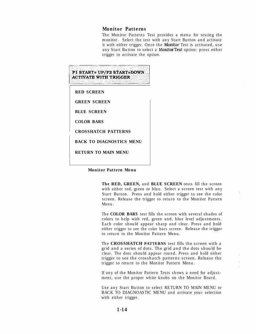
Monitor PatternsThe Monitor Patterns Test provides a menu for testing themonitor. Select the test with any Start Button and activateit with either trigger. Once the Monitor Test is activated, useany Start Button to select a MonitorTest option: press eithertrigger to activate the option.
RED SCREEN
GREEN SCREEN
BLUE SCREEN
COLOR BARS
CROSSHATCH PATTERNS
BACK TO DIAGNOSTICS MENU
RETURN TO MAIN MENU
Monitor Pattern Menu
The RED, GREEN, and BLUE SCREEN tests fill the screenwith either red, green or blue. Select a screen test with anyStart Button. Press and hold either trigger to see the colorscreen. Release the trigger to return to the Monitor PatternMenu.
The COLOR BARS test fills the screen with several shades ofcolors to help with red, green and, blue level adjustments.Each color should appear sharp and clear. Press and holdeither trigger to see the color bars screen. Release the triggerto return to the Monitor Pattern Menu.
The CROSSHATCH PATTERNS test fills the screen with agrid and a series of dots. The grid and the dots should beclear. The dots should appear round. Press and hold eithertrigger to see the crosshatch patterns screen. Release thetrigger to return to the Monitor Pattern Menu.
If any of the Monitor Pattern Tests shows a need for adjust-ment, use the proper white knobs on the Monitor Board.
Use any Start Button to select RETURN TO MAIN MENU orBACK TO DIAGNOASTIC MENU and activate your selectionwith either trigger.
1-14

Driver Board TestThe Driver BoardTest provides the operatorwith a way to testthe Gun Coils, the Flashlamps, and the Gun LEDs. Press anyStart button to select the Driver Board Test. Press eithertrigger to activate the test.
This test cycles through and pulses the Gun Coils (left, thenright), the Flashlamps (left side, then right side). and theGreen and Red LEDs (left gun, then right gun). To stop thecycle and continually pulse a particular coil, lamp or LED,press and hold the Service Credit Switch when the desiredcoil, lamp or LED is activated, As each device is activated,the name is displayed on the screen.
Press any Start Button to return to the Diagnostic Menu.
Burn-in TestThe Bum-in Test continually repeats the CPU Board Test.
Press any Start Button to select the Bum-inTest; then, presseither trigger to activate the test. When the Bum-in Testdetects an error, the test stops and displays an error messageon the screen. The Audit Table specifies the number of Bum-in cycles successfully completed. Use this test to find inter-mittent CPU problems.
To exit this test, switch the game Off then On again.
1-15

COIN BOOKKEEPINGTo enter the Coin Bookkeeping from the Main Menu, pressany Start Button to select the Coin Bookkeeping option;then, press either trigger to activate it.
The Coin Bookkeeping Table records the coinbox totals andgame play counters. The left side of the table names thebookkeeping item: the right side shows the number of coins,credits, or plays for each Item.
To exit Coin Bookkeeping, press any Start Button to selectRETURN TO MAIN MENU; then, press either trigger toactivate it.
LEFT SLOT COINS. 0
RIGHT SLOT COINS 0
: THIRD SLOT COINS 0
i FOURTH SLOT COINS 0
I SERVICE CREDITS 0
: PAID CREDITS 0
:, GAME!3 STARTED 0
GAMES CONTINUED 0
TOTAL PLAYS 0
PLAYS UNTIL HIGH SCORE RESET 5000
MORE DETAILED DATA
fRETURN TO MAIN MENU
Coin Bookkeeping Table
LEFT SLOT COINS 0
RIGHT SLOT COINS 0
THIRD SLOT COINS 0
FOURTH SLOT COINS 0
TOTAL COLLECTIONS 0
CLEAR COIN METERSRETURN TO MAIN MENU
-
Total Collection Table
1-16

GAME AUDITSTo enter Game Audits from the Main Menu, press any StartButton to select the Game Audits option; then, press eithertrigger to activate it. To advance to the next (or return to theprevious) page of the Game Audit Table, press any StartButton to select either “Next Audit Page”, or “Previous AuditPage”; then, press either trigger to change the page.
The Game AuditsTable records the game play statistics. Theleft side of the table names the Audit item: the right sideshows the amount of play.
Page 1 of Audit Table
1-17
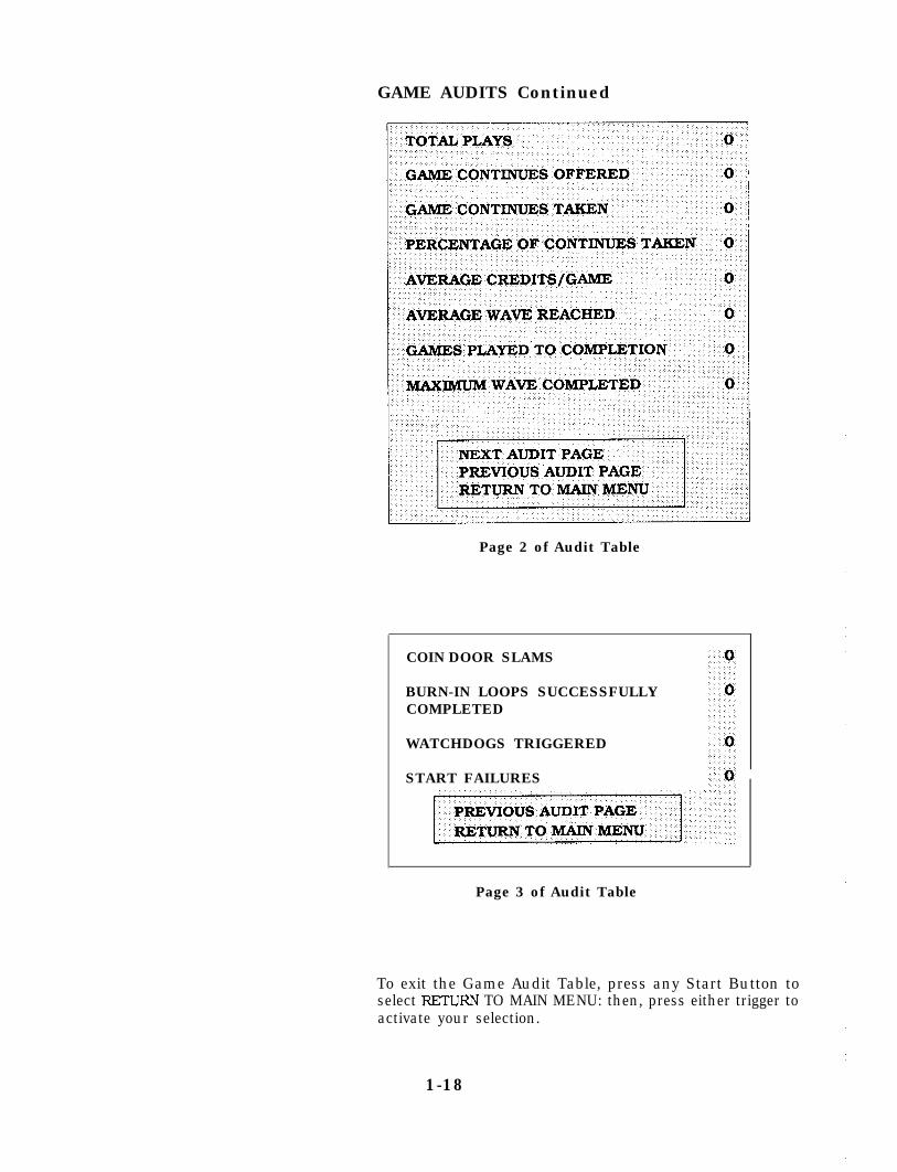
GAME AUDITS Continued
Page 2 of Audit Table
COIN DOOR SLAMS
BURN-IN LOOPS SUCCESSFULLYCOMPLETED
WATCHDOGS TRIGGERED
START FAILURES
Page 3 of Audit Table
To exit the Game Audit Table, press any Start Button toselect RETURN TO MAIN MENU: then, press either trigger toactivate your selection.
1-18

GAME ADJUSTMENTSPress any Start Button to select the Game Adjustment optionon the Main Menu: then, press either trigger to activate it.
The Game Adjustments Menu allows the owner/operator tochange the Game Pricing and Game Difficulty.
The Game Adjustments Menu offers several options. Eachoption has its own menu. Press any Start Button to selectan option; then, press either trigger to activate that option.On the next menu screen, press any Start Button to selectthe item you wish to modi@; then, press either trigger toactivate that item. The activated item provides a settingchoice. Press any Start Button to change the current settingvalue: then, press either trigger to lock in the new settingvalue. Pressing the Player 1 Start Button increases thesetting value. Pressing the Player 2 Start Button decreasesthe setting value.
To exit the Adjustments Menu, press any Start Button toselect RETURN TO MAIN MENU: then, press either trigger toactivate your selection.
RETURN TO MAIN MENU
STANDARD PRICING
CUSTOM PRICING
FREE PLAY
GAME DIFFICULT-Y
ENERGY PER PLAY
BOMBS PER PLAY
MIN. TIME PER PLAY
ATTRACT MODE SOUND
AUTO HIGH SCORE RESET
HIGH SCORE ENTRY
ALLOW GAME CONTINUE
RETURN TO MAIN MENU
Game Adjustment Menu
1-19

GAME ADJUSTMENTS Continued
Standard PricingStandard Pricing allows the operator to choose any of the“Standard” selections for the Standard Pricing Table.Note: DIP Switch settings override Standard Pricing changesmade from the Game Adjustment Menu.
Custom PricingCustom Pricing allows the operator to install pricing otherthan that of the Standard Pricing Table. Custom Pricing alsoallows the operator to select the maximum amount of creditsper game, the amount of credits required to start a game, andthe amount of credits required to continue a game.Note: DIP Switch settings override Custom Pricing changesmade from the Game Adjustment Menu.
Free PlayThis option allows the operator to select free play. Thesettings for the adjustment are:
- No (factory)- Yes
Game DifficultyThe operator chooses the the difficulty level of the game. Thesettings for this adjustment are:
- 1 Easiest- 5 Medium (factory)- 10 Hardest
Energy Per PlayThe operator chooses the amount of energv a player receiveseach time he/she starts or continues a game. The settingrange for this adjustment is:
- 5 Lowest- 100 Medium (factory)- 200 Highest
Bombs Per PlayThe operator chooses the amount of bombs a player receiveseach time he/she starts or continues a game. The settingrange for this adjustment is:
- 1 Lowest- 25 (factory)- 99 Highest
Minimum Time Per Play*The operator chooses the minimum time in seconds eachplayer is guaranteed to receive for each play. The settingrange for this adjustment is:
- 30 Lowest- 45 (factory)- 300 Highest
* Not in effect during end-of-wave confrontations: Forexample, Tank Hunter Killer.
l-20

Attract Mode SoundThe operator determines whether the game will make soundsduring the Attract Mode. The settings for this adjustmentare:
- On (factory)- Off
Auto High Score ResetThe All -time High Score Table is reset to factory values eachtime this many plays occur. The setting range for thisadjustment is:
- Off- 250 Lowest- 5000 (factory)-25. 000 Highest
High Score EntryThe operator determines whether the game will allow HighScore Entry and Table display. The settings for the adjust-ment are:
- No- Yes (factory)
Allow to ContinueThe operator determines whether the game allows a player tocontinue after all the players are dead. The setting for thisadjustment are:
- Never- Sometimes- Always (factory)
1-21

Standard Pricing Table
NAME
USA 1USA 2USA 3USA 4USA 5USA 6USA 7USA 8USA ECA
German 1German 2German 3German 4German ECA
France 1France 2France 3France 4France 5France 6France 7France 8France 9France 10France 11France 12France ECA
Canada 1/2x 25C. 3/$1.00 25t
Swiss 1 l/lF. 6/5F 1FSwiss 2 l/lF. 7/5F 1FSwiss 3 l/lF. 3/5F 1F
UK 1U K 2UK ECAUK w/CCU
1/2OP. 3/5OP2/2OP, 5/5OP1/3OP. 2/5OP. 4/ELOO1/3OP. 2/5OP, 4/s1.00
2OP2OPEl.00ecu
Spain 1 l/25 Peseta. 5/ 100 Peseta 25 PesetaSpain 2 l/25 Peseta, 4/ 100 Peseta 25 Peseta
Australia 1Australia 2
1/3 x 204. 2/$1.001/5x 20@. l/$1.00. 3/$2.00
20t20t
Japan 1Jaoan 2
L/l00 YenZ/l00 Yen
100 Yen100 Yen
Austria 1 l/SSch. 2/lOSch jSchAustria 2 l/2x 5Sch. 3/2x losch jSch
Belgium 1 1/20F 20FBelgium 2 V20F 10FBelgtum 3 !/20F 10FBelgium ECA I /25F, 4/ 1OOF j0F
Sweden I/3 x 1K.r. 2/5Kr 1Kr
New Zealand 1 ./3 x 20tNew Zealand 2 ./2 x 2oc
Vetherlands /lHfi. 3/2.5HfI
Finland
Vorway
rb”morL
SETTINGZredit/Coin
LJwrCHUTE
l/25+l/50$l/50$. 3/$1.00l/50$. 4/$1.00l/25$. 4/$1.001/5oc. 2/$1.00. /5oc, 3/$1.00l/50@, 4/$1.00l/25+. 4/$1.00
25t25425025Q25Q25t25t25t$1.00
l/ 1DM. 6/5DM 1DMl/lDM. 7/5DM 1DMl/lDM. 8/5DMl;lDM, 5;5DM
1DM1DM
l/lDM. 2/2DM, 6/5DM 5DM
2/5F, 5/10F2/5F. 4/10F1;iF; 3;10F1/5F, 2/10F2/5F, 5/ 10F. 1 l/2 x 10F2/5F, 4/10F, 9/2x 10F1/5F. 3/10F. 7/2x 10F1/5F. 2/10F. 5/2x 10Fl/3 x 1F. 2/5Fl;2 x IF. 3;5Fl/3 x 1F. 2/5F, 5/2x 5Fl/2 x 1F. 3/5F. 7/2x 5Fl/3 X 1F. 2/5F. 5/2x 5F
l/500 Lire
5F5F5F5F5F5F5F5F1FIF1F1F1F
500 Lire
!OC!OC
!Hfl
.Mka
.Kr
__
Custom Pricing
ZENTER RIGHTCHUTE CHUTE
25425t25C25*
f::: 25425t
$1.00 25C$1.00 25C101 25t
5DM5DM5DM5DM
1DM 2DM
10F10F10F10F
I IOF10F10F10F
I 5F5F5F5F
10F 5F
2OP
5OP5OP5OP
100 Peseta100 Peseta
I
I 100 Yen100 Yen
1OSch1OSch
20F
t
20F20F
5F 20F
5Kr
FOURTHCHUTE
5t
10 P
Pl START= UP/P2 START=DOWNACTIVATE WITH TRIGGER
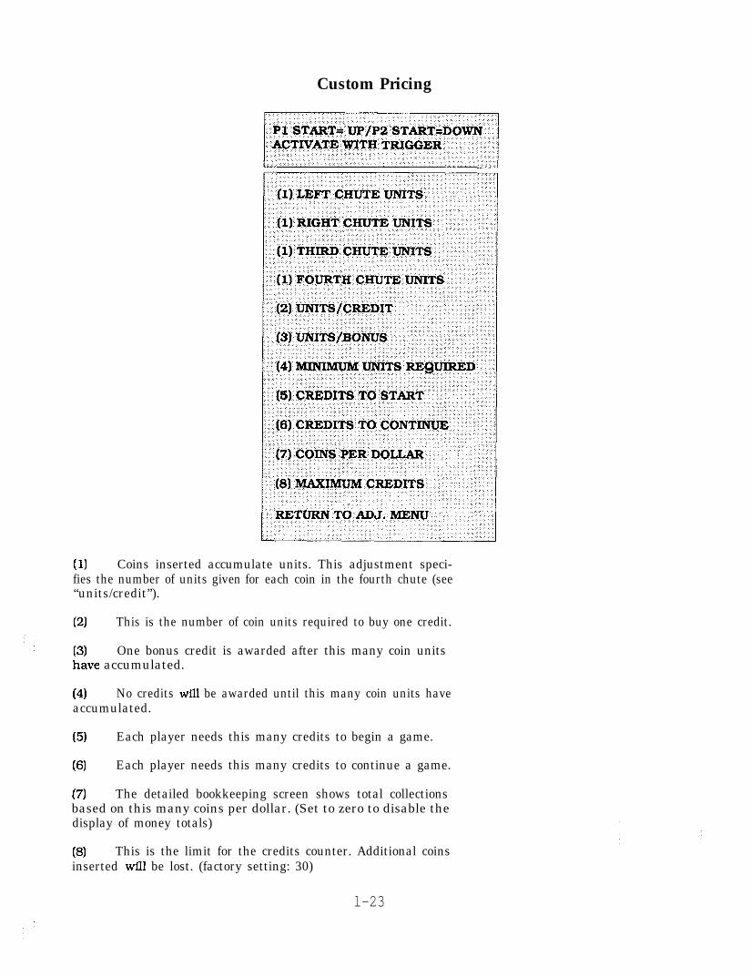
Custom Pricing
(1) Coins inserted accumulate units. This adjustment speci-fies the number of units given for each coin in the fourth chute (see“units/credit”).
(2) This is the number of coin units required to buy one credit.
Eve accumulated.One bonus credit is awarded after this many coin units
(4) No credits will be awarded until this many coin units haveaccumulated.
(5) Each player needs this many credits to begin a game.
(6) Each player needs this many credits to continue a game.
(7) The detailed bookkeeping screen shows total collectionsbased on this many coins per dollar. (Set to zero to disable thedisplay of money totals)
(8) This is the limit for the credits counter. Additional coinsinserted will be lost. (factory setting: 30)
l-23
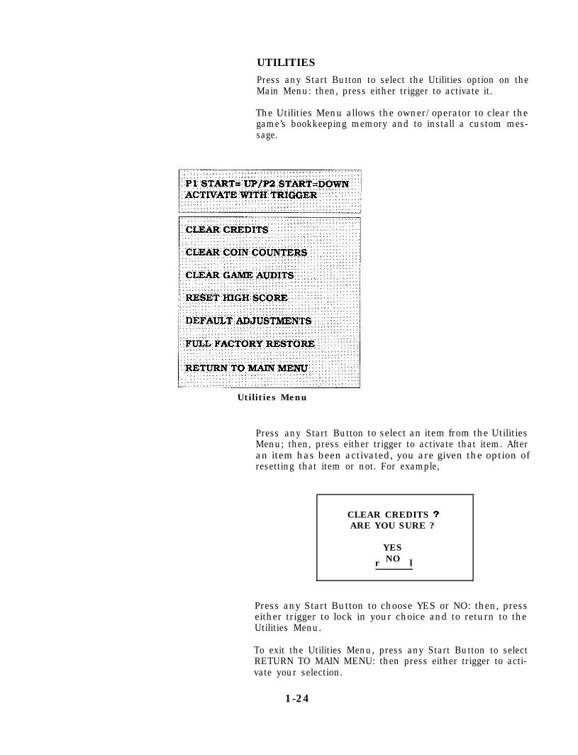
UTILITIES
Press any Start Button to select the Utilities option on theMain Menu: then, press either trigger to activate it.
The Utilities Menu allows the owner/operator to clear thegame’s bookkeeping memory and to install a custom mes-sage.
Utilities Menu
Press any Start Button to select an item from the UtilitiesMenu; then, press either trigger to activate that item. Afteran item has been activated, you are given the option ofresetting that item or not. For example,
CLEAR CREDITS 3ARE YOU SURE ?
YES
r lNO
Press any Start Button to choose YES or NO: then, presseither trigger to lock in your choice and to return to theUtilities Menu.
To exit the Utilities Menu, press any Start Button to selectRETURN TO MAIN MENU: then press either trigger to acti-vate your selection.
1-24

CALIBRATE GUNS
Press any Start Button to select the Calibrate Guns optionon the Main Menu: then, press either trigger to activate it.
The Calibrate Guns option allows the operator to align theguns.
Once the option is activated, the screen gives the operatorthree targets to aim and shoot at. First with the left gun, then%;;th the rlrrht cr,.m Thcz tqrrrntc QT-P In,-&m-l in the tnn l&tlLll LllC Ll~l;lrL guLI. IIIL LUl&LL3 U&c- A"L-ULL.U YI LIIL L"p ALAL,
center, and bottom right of the screen.
When the guns are calibrated correctly, the message**Calibration Successful**
appears on the screen and the data is stored in the CMOSRAM. The game automatically returns to the Main Menu.If gun calibration is not successful the following messageappears:
**CMOS RAM ERROR**Unable to write calibration values.
Guns are not aligned.Press any button to continue.
Begin again to calibrate the guns. If you make a mistake,press any Start Button to abort the procedure and start over.
To exit the Main Menu from the Calibrate Guns option, pressthe Player 2 Start Button to select EXIT TO GAME OVER:then, press either trigger to activate your selection.
+er Left
:;
.\
Center@-\ .
The Gun Assemblies are cali-brated from the factory. How-ever, if you change boards orreplace ROMs, RAMS, or thebattery, you must recalibratethe guns. Guns do not operateunless they are calibrated.
Check Gun calibration whenyou receive your game. Gunsmight of been jarred duringshipping and need to be re-calibrated.
It is necessary to turn Off theTest Switch in the coin door,and/or Switch #8 of DIP SwitchBank 2 on the CPU Board toenter the Game Over Mode.
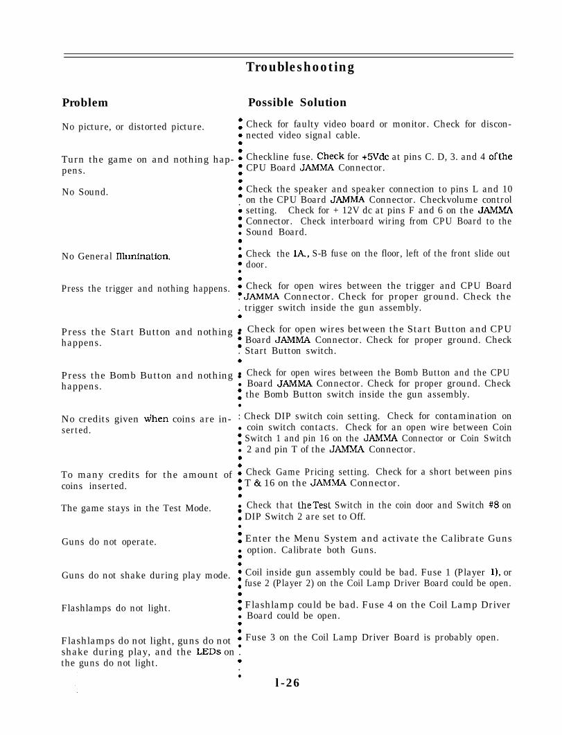
Problem Possible Solution
Check for faulty video board or monitor. Check for discon-nected video signal cable.
0
No picture, or distorted picture. 0a0a
Turn the game on and nothing hap- :pens. a
0No Sound. a
b.000l
0l
No General Ilhmination. 00l
0Press the trigger and nothing happens. :
Checkline fuse. Check for +SVdc at pins C. D, 3. and 4 oftheCPU Board JAMMA Connector.
Check the speaker and speaker connection to pins L and 10on the CPU Board JAMMA Connector. Checkvolume controlsetting. Check for + 12V dc at pins F and 6 on the JAMMAConnector. Check interboard wiring from CPU Board to theSound Board.
Check thedoor.
lA., S-B fuse on the floor, left of the front slide out
Check for open wires between the trigger and CPU Board. JAMMA Connector. Check for proper ground. Check the. trigger switch inside the gun assembly.0
Troubleshooting
Press the Start Button and nothing ll Check for open wires between the Start Button and CPUhappens. : Board JAMMA Connector. Check for proper ground. Check
. Start Button switch.
Press the Bomb Button and nothing ll Check for open wires between the Bomb Button and the CPUhappens. l Board JAMMA Connector. Check for proper ground. Check
: the Bomb Button switch inside the gun assembly.l
No credits given dhen coins are in- : Check DIP switch coin setting. Check for contamination onserted. l coin switch contacts. Check for an open wire between Coin
: Switch 1 and pin 16 on the JAMMA Connector or Coin Switchl 2 and pin T of the JAMMA Connector.0
To many credits for the amount of : Check Game Pricing setting. Check for a short between pinscoins inserted. : T & 16 on the JAMMA Connector.
0The game stays in the Test Mode.
Guns do not operate.
l Check that theTest Switch in the coin door and Switch #8 on: DIP Switch 2 are set to Off.l
: Enter the Menu System and activate the Calibrate Gunsl option. Calibrate both Guns.a
Guns do not shake during play mode. : Coil inside gun assembly could be bad. Fuse 1 (Player 11, or: fuse 2 (Player 2) on the Coil Lamp Driver Board could be open.0
Flashlamps do not light. : Flashlamp could be bad. Fuse 4 on the Coil Lamp Driverl Board could be open.0
Flashlamps do not light, guns do not : Fuse 3 on the Coil Lamp Driver Board is probably open.l
shake during play, and the LEDs on .the guns do not light. 0
.l
l -26

S E C T I O N
t w o
Parts
2-1

Cabinet Hardware
Cabinet Assembly A- 14762Caster Wheel B- 13086Leg Leveler Plate 01-9155Leg Adjuster, 3.0’ 08-7377
Front Door Assembly A- 14763Latch Bracket 01-6994Wood Door 1 l-1022
Coin Door Assembly A- 14975Test Switch A-13115Coin Door Cable H- 13842Coin Door Cable H- 14923Coin Door, U.S.A. 09-20000-v- 15OKQ Volume Control Pot. 5014-12925-00
20” Vent Hole Cover 03-7602Marquee Retainer 03-8252-2Lamp Lock 03-8327Glass Edge Channel 03-835825” CRT Bezel 03-8497- 1Clear Glass Marquee 08-7456-12Wood Rear Deck 1 l-1021Wood Mirror Support 1 l-1024Toggle Latch 20-9347Long Arm Key T-20 20-9620Long Arm KeyT-15 20-9680Screened Marquee 3 1 - 1632 -40009Screened CRT Glass 3 1- 1633-40009Screened Mirror 31-1643
Speakers
Speaker & Cap Assembly A- 14968Speaker Cable H- 14922Cap. lOmF, NP. 50V 5045-12914-004R, Tweeter Speaker 5555- 12924-006”. 4Q, Round Speaker 5555- 12929-00
Speaker Grille 01-10283Steel Speaker Screen 4506-01103-24B
Manuals
Monitor ManualInstruction Manual
Monitor
16-3000- 10316-40009- 10 1
Monitor Support Bracket A-. 14769Monitor Support Bracket A- 1477025” Monitor 5675- 12787-00
2-2

PC Boards
Chassis Panel AssemblyWood Chassis PanelPower Supply AssemblySound Board AssemblyY-Unit CPU Assembly
Coil Lamp Driver BoardDual Flashlamp Board
Twist Lamp Socket#906 Bulb
A- 14794- 11 l-990A- 14205A- 14732-40009A-14818-40009A-14915A-1502124-876724-8802
Transformer Assembly
Power Pack Assembly A-15123Line Cord Assembly A- 13340Power Pack Chassis Assy A-15124Power Pack Jumper Cable H- 13265Line Filter Jumper Cable H- 13344Transformer Jumper Cable H- 13378Varistor, 13OV. 1OJ 50 17-09044-00Line Filter, 5 Amp 5102-08895-00Power Transformer 5610-12945-00Fuse, SB. 5A. 250V 5731-09651-00Fuse Holder, Panel 5733- 10358-00
Fluorescent Lamp Assembly
Fluorescent Housing & Bracket C-12679Housing Mounting Brkt 01-9146Light Fixture 20-959018” Fluorescent Bulb, 15 W 24-8809
Control Panel
Control Panel AssemblyGun AssemblyControl Panel CableEarth Ground CableLatch BracketWood Control PanelToggle LatchRed PushbuttonBlue Pushbutton
A- 14764A-14415H- 14920H- 1495001-69941 l-102320-934720-9687- 120-9687-3
2-3

Cables
Line Voltage Cable AssemblyVideo SW/Power CablePower Pack Jumper CableLine Filter Jumper CableTransformer Jumper CableCoin Door CableGround Jumper CableMachine Gun CableMain Harness Cable
Video Signal CableSecondary Jumper CableLamp/Speaker CableControl Panel CablePiezo Speaker CableCoin Door CableVideo Extension CableSound Power Speaker CableG.I. CableGun Ground CableControl Panel Earth Ground
A- 14969H-10217-4H- 13265H- 13344H- 13378H- 13842H- 13953H- 14904H- 14905H- 14949H- 14906H- 14907H- 14920H- 14922H- 14923H- 14924H- 14925H- 14926H- 14927H- 14950
2-4

A-14205Power Supply Switcher Assembly
Part Number DescriptionH-10217-4 Video SW/Power CableH- 13953 Ground Jumper Cable01-9254 Shield0 l-9938 Mounting Bracket
lo_
I0 0
GRAY/GREEN
GRAY/YELLOW
GREEN ’ GRAY’
/,
BLAbK BLkK
\GROUND JUMPER
1 pjlgigl \
2-5

A- 148 18-40009CPU Board Assembly
$. .. .. .. .. .. .. .. .. .. .. .. .. .. .. .I. .. .. .. .. .. .. .. .. .. .. .. .. .. .. .0
sl=i
2-6

A-14818-40009CPU Board Parts
Part No.
l
5281-09737-005317-12211-00
5317-12212-00
5317-12208-00
5340- 12840-005700- 12047-005340-12213-005521-12934-005521-10318-005283- 10468-005019-10849-005317-12305-005700- 12253-005280-09309-005281-09487-005434-12255-065700-099 15-005311-12287-00
5700-10176-00531 l-12285-005340-12014-005283-10552-005370- 12602-005317-12023-005700- 12088-00
5700-12254-005317-12024-005700-08985-0050 lo-0899 l-005010-10204-0050 lo- 10205-0050 lo- 10000-0050 10-092 19-005010-08772-005010-09001-0050 10-09036-00
5010-09416-0050 10-08997-0050 10-09534-00
Ckt.Desi@mtor Description
Bare PC Brd.Ul IC, 74LS86 XORU2, U20. U24, U43 IC, 74ALS.54 1U61. U62. U70U3, US, U7, U2 1, U25 74ALS574U50. U58, U63, U64U71. U72. U74. U79.us41 u85’u4. u22, u54-u57 74ALS245
U59. U60, U75-U78U80. U81. U94. UllOU5. U23 IC.8Kx8SRAMUS; U52. U53. U65 24-pin SocketUlO. Ull. U28-U33 IC. 4461 VRAMU16 50 MHZ Xtalu17 24 MHZ XtaIu19, u45U27. U34. U44. U48u35U36u37U38u39U40-U42U47. U46, U87, UlOOUlOl. u103. u104u49U51. U73. U82U66-U69U83
IC. 74F74IOOQ DIP Res.IC. 74AISO068-pin SocketIC. 7407IC. 74LS74IC. MAX69120-pin SocketIC. 74HC541
28-pin SocketIC, 74HC573IC. 4464 DRAMIC!. 74FO4IC, ULN2064BIC. 74ALSl38
U89-U93. U95-U98 32-pin Socketu105-u109.Ulll-u114u99 144-pin Socketu102 IC. 74ALSl39
5671-09019-06555 l-09822-005645-09025-005641-12551-005881-12315-005791-10862-085791-12461-125791-10850-005791-12461-045791-12461-20579 l-09437-005791-12461-105700-12252-005791-12461-05A-14819A-5346-40009- 15400-12220-00A-5346-40009-2A-5346-40009-3
u115 40-pin Socket
A-5346-40009-105340- 12558-00A-5346-40009-l 1
Rl.R24. R27 Res. 4.7KQ 5% 1/4W A-5346-40009-6R2. R7. R12 Res. 1KQ 2% 1/4W A-5346-40009-7-R3. R8. R13 Res. 2Kn 2% 1/4W A-5343-40009- 1R4, R9. R14 Res. 3.9KD 5% 1/4W A-5343-40009-2R5. RlO. R15 Res. 8.2KD 5% 1/4W A-5343-40009-3R6. Rll. R16 Res. 15KG 5%1/4W A-5343-40009-4P23. R25 Res. 33OR 5% 1/4W A-5343-40009-5P26, R29-R34, Res. 1OOG 5% 1/4W A-5341-12952-02R50. R51 A-5343-40009-7R35-R37. R46-R48 Res. 47OR 5% 1/4W A-5343-40009-8R38-R45 Res. 2.7KD 5% 1/4W A-5343-40009-9W2.W8,Wll.W12. Res. On 5410-12239-00w14, w21, w22.W24. A-5343-40009-10Vv27. W29. W30. W32. A-5341-12952-03W34, w36,W39, w41. A-5343-40009-12W42, W45. W47. W48. A-5343-40009-13W50. W52, W55, W57, A-5343-40009-14W58. W60. W62. W65. A-5341-12952-01W68. W69. W71, W73. A-5343-40009-16W75. W77. w80. w83 A-534340009- 17
A-5343-40009-18A-5346-40009-85880- 11056-0003-8338- 1
Pm-t No. Ckt.Designator Description
Cap. .Ol Irfd 1OVCap. lC@fd 1OVCap. .OOlpfd 1OVCap. lOI.tfd 1OVCap. .l+fdSIP. 47o.G. 5 Res.
5043-08980-005040-08986-005043-09845-00504 l-09243-005043-8996-005019-12611-00
5019-09362-00
5091-10143-005060- 10396-00
BCl, c2, c5, Cl0c3. c4C6-C9Cl1SRl. SR2, SR8SR9. SR12. SR13SR18SR3. SR4, SR6
SR7. SRll. SR15SR17. SR19SR24SRC 1 -SRCSSR5SRC4. SRC5SRC 10. SRC14SRC 16LEDl. LED 2LlDSl. DS2SW1Bl5254J6.57
::A. J9B58512U12-U15513
U8U36u40u41U42u49U52u53U65U89u90u91u92u93u95U96u97U98u99u105U106u107U108u109Ulllu112u113u114u115Bl
SIP. 4.7KG. 9 Res.
SIP. 4701;r. 9 Res.SIP. 4.7KG 470pf
LED, RedInductor. 4.7UHDIP. SW. 16 DinPushbuttonSw.Battery Holder8-ptn Header12-pin Header26-pin Ribbon COM.4-pin Header20-pin Header20-Din Ribbon COM.10-&r Header24-ptn Socket5-pin HeaderCPU Sub-assemblyIC, PLD Color RAM CtrlIC. TM34010-50. GSPIC. PLD Address DecodeIC. Video RAM ControlIC. PLD Local ControlIC. Static RAM, 15OnsIC. PLD Video RAM Seq.IC. PLD Image ROM CtrlIC. PLD Misc. ControlIC. Game EPROMIC. Game EPROMIC. Game EPROMIC. Game EPROMIC. Game EPROMIC. Image ROM, 2M-01IC. Game EPROMIC. Game EPROMIC, Game EPROMIC. Custom ASICIC. Game EPROMIC. Image ROM, 2M-02IC, Game EPROMIC, Game EPROMIC. Game YPROMIC. Image ROM, 2M-00IC. Game EPROMIC. Game EPROMIC, Game EPROMIC. PLD Autoerase CtrlBattery, Lithium. 3Vl/4” Spacer
Notes: 1. See Section 3 for schematic2. *= Not available for individual sale.
2-7

L! IND
lCA
TE
5K
EY
ING
P
\N
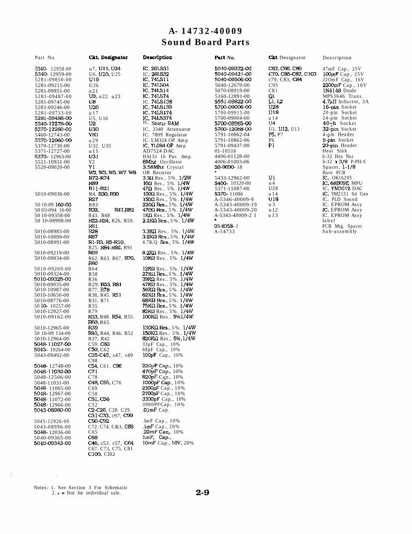
A- 14732-40009Sound Board Parts
Part No. cm. Designator DescriptSon Part No. Ckt Designator Description
5340- 12958-005340- 12959-005281-09850-005281-09215-005281-09851-005281-09487-005281-09745-005281-09246-00
u7, Ull. u24U6. U10. U25u19U26u21u9, u22. u23
EOu17
IC. 26LS31IC, 26LS32IC. 74LSllIC. 74LsO4Ic!. 74LS14Ic!. 74IS74IC. 74LS138IC, 74IS139IC, 74LS174IC, 74Ls374IC S~‘~c ~“~IC, 3340 AttenuatorIC. 7809 RegulatorIC. LM324 OP AmpIC, TLo84 OP AmpAD7524 DACHA131 16 Pwr. Amp.8Mhz Oscillator3.58Mhz CrystalOR Resistor3.3f2 Res.. 5%. 1/2WIOR Res., 5%. 1/4W47Q Res.. 5%. 1/4W1OOn Res., 5%. 1/4w15OR Res., 5%. 1/4w22on Re?., 5%. 1/4w47oiL I&s., 5%. 1/4wIKQ Res.. 5%. 1/4W2.2KQ 1~s.. 5%. 1/4w
5040-09332-005043-09421-005040-09506-005040-12670-005070-08919-005160-12891-00
5700-09006-005700-09915-005700-09004-00*7M_fV+3-5-QQU,“” “U.,5700-12068-005791-10862-045791-10862-065791-09437-0001-105164406-01128-004006-01003-0620-9690- 18l
5433-12962-005400- 10320-005371-11087-005370- 11086A-5346-40009-9A-5343-40009-19A-5343-40009-20A-5343-40009-2 1I03-6358- 1A-14733
c63. Cfx. c80C70. C85-C87, Cl03c79, C83, c84C95CR1
?; I2Ui8U18u14IU4U3, U12. U13P5. P7P6PI
47mF Cap., 25V1OOmF Cap., 25V22OmF Cap., 16V22-F Cap., 16VlN4148 DiodeMPS3646 Trans.4.7@l Inductor, 3A16-Din Socket20-pin Socket24-pin Socket40-h Socket32-$n Socket4-pin HeaderS-&n Socket2d-pin HeaderHeat Sink6-32 Hex Nut6-32 x 3/8 P-PH-SSpacer, l-1/8Bare PCBIC. OK16295IC. 68B09E MPUIC, YM3012 DACIC. YM2151 Sd GenIC. PLD SoundIC. EPROM AssyIC. EPROM AssyIC. EPROM AssylabelPCB Mtg. SpacerSub-assembly
5281-09733-005281-09466-005340-12278-005370-12260-005460-12743-005370-12960-005370-12730-005371-12727-005370- 12963-005521-10931-005520-09020-00 Yl
W2.Wx.W5.W7.W8
EL215010-09036-00 R4, R30. R90
50 10-09 160-0050 IO-094 16-0050 10-09358-0050 10-08998-00
R27R83R32. R41.I762R43. R68R22-IB4, R26, R59.R61
5010-08983-00 Ii28 3.3KQ Res.. 5%. 1/4W5010-10000-00 R67 3.9KnRes.. 5%. 1/4W5010-08991-00 Rl-R3. R5-RlO. 4.7K.Q Res.. 5%. 1/4w
5010-09219-005010-09034-00
R25, R8J-R86, R91R69R62. R63. R67. R70.R80
5010-09325-005010-09035-005010-10987-00
5010-09269-00 R645010-09324-00 R58
R36R29. R53. R81R77. R78.R38, R45. R5 1R31. R71R35
5010-10650-005010-08776-0050 lo- 10257-005010-12927-005010-09162-00
5010-12965-0050 10-09 134-005010-12964-005048- 11027-005043- 10264-005043-09492-00
5048- 12748-005048- 11030-005048-12506-005048-11031-005048- 11065-005048- 12967-005048- 11072-005048- 12966-00
5045-12926-005043-08996-005048- 12036-005040-09365-005040-09343-00
U5, U16ii2u30VRlu29U32. U33u15u31Y2
R79R33. R48. R54. R55.R60, R65R39R40. R44, R46. R52R37, R42C59. C60c50. C62C35-C45, c47, c49C98
C51. C56C52C2-C26. C28. C29.C31c33. c97, c99c90-c92C72. C74. C&3, C89C65C68C46. c53. c57, c64C67. C73, C75. C81ClOO. Cl02
c54, C61. c96c71C78C48. C55, C76C69C58
Notes: 1. See Section 3 For Schematic2. l = Not for individual sale.
8.2K.Q Res.. 5%. 1/4W1oK.Q Res.. 5%. 1/4w
12Kn Res.. 5%. 1/4w27KQ Res., 5%. 1/4W39KCl Res.. 5%. 1/4w47KR Res.. 5%. 1/4w56Kn Rcs., 5%. 1/4w62KS2 Res.. 5%. 1/4W68KQ I&s., 5%. 1/4w75Kn Res.. 5%. 1/4w82K.Q Res.. 5%. 1/4w1CQm Res.. 5%1/4W
13OKR Res.. 5%. 1/4W15OKQ Res.. 5%. 1/4W82OKQ Res., 5%, 1/4W33pF Cap., 10%68pF Cap., 10%1OOpF Cap., 10%
220DF Cau.. 10%47&F Cap.; 10%82OpF Cap.. 10%lO&pF Cgp., 10%2200pF Cap., 10%27OOpF Cap., 10%3300pF Cap., 10%3900PFCap.. 10%.OlmF Cap.
.lmF Cap., 10%
.lmF Cap., 20%
.22mF Can. 10%
2-9
1mF. Cap:.1OmF Cap., 16V, 20%
Ulu4U28u14U18u3u12u13
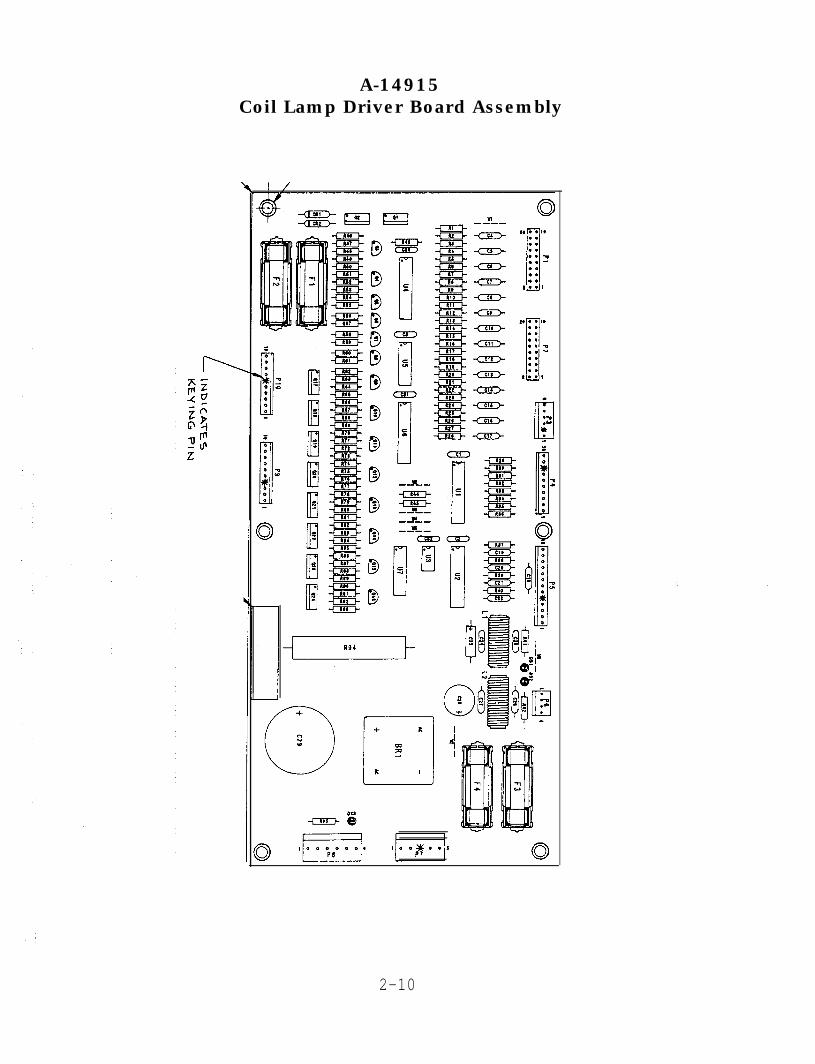
A-14915Coil Lamp Driver Board Assembly
I, . . I.:::: 9I-::::t..,
1. . e I.:::: -o1:: u
::L..,
2-10

A-14915Coil Lamp Driver Board Parts
Part Number
5315-12031-005372-12901-005311-12668-00531 I-12669-005434-12910-005162-12635-005160-10269-005010-09034-00
5010-09162-00
501 O-0941 6-00
5010-09224-005010-08991-00
5010-08997-00
5010-12480-00
5010-09187-005010-10983-005012-12632-00501 O-09085-005010-09534-005070-09054-005043-08980-00
5043-09492-005040-12751-005048-11031-005040- 10974-005551-09822-005100-09418-005730-063 1 l-005730- 12985-00573 l-09432-005733-12060-015671-09019-00579 l-09437-005791-12461-065791-12461-105791-12461-135791-12461-045791-10862-055791-10862-065190-09016-0003-8338-l
Ckt. Designator
Ulu2U4, U6u 5u3
^._ #-._aQi. 82, b~l1-gz493, Q4,Q9-916Rl, R3, R5, R7, R9,Rll, R13. R15, R17,Rl9, R21, R23, R25,R27, R37, R38, R39.R40, R44. R45R2, R4, R6, R8, RlO,R12, R14, R16, R18,R20, R22, R24, R26R28R29-R36. R49, R53,R65, R69, R73, R77.R81, R85. R89. R93R41. R42R43, R4.8, R52, R@,R68, R72, R76, R80,R84, R88, R92R46, R50, R62, R66,R70, R74, R78. R82,R86. R91R47, R51, R6.3, R67,R71, R75, R79. R83,R87, R90R54. R56, R58, R60R55, R57. R59. R61R94R95Wl. W6.W7CRl, CR2Cl-C3, C23, C24,C30-C32c4-c7, c9-c22C25C26. C27C28Ll, L2BRlFl, F2F3F4
DS 1, DS2, DS3Pl, P2P3P4, P9, PlOP5P6P7
Description
IC. 74HCT244IC, ADC0844IC, 74HCT273IC, 74HCTl4IC, MAX699Trans., TIPiG2Trans., 2N3904Res., lOKn, 1/4w, 5%
Res., lOOKR, 1/4W, 5%
Res.. 47oR, 1/4w, 5%
Res.. 27OR, 1/4W, 5%Res.. 4.7Kn. 1/4w, 5%
Res., 2.7KR, 1/4w, 5%
Res., 68R. 1/4w. 5%
Res., 15022. 1/4w. 5%Res.. l.BKK& 1/4W, 5%Res., .1221, low, 10%Res., 1.5KR, 1/4w, 5%Jumper WireDiode, lN4004. 1ACap., .OlmF. 5ov
Cap., lOOpF, 50VCap., 4.7mF. 1OVCap., .OOlmF, 50VCap., 1 OOmF, 35VInd., 4.7pH, 3ABridge Rec., lOOV, 35AFuse, 3A, FB, 250VFuse, lA, FB, 250VFuse, 7A, SB, 125VFuse HolderLED Red20-pin Headerg-pin Header . 100lo-pin Header . 10013-pin Header . 1004-pin Header . 1005-pin Header .1566-pin Header .156Trans., 2N4403Spacer, PCB Mtg., l/4”
2-11

2-12

A-14415Gun Parts
Item Part Number Description
1 A- 144442 A- 145903 A-149144 A- 144555 __ T\rT\nuJ-uo;Lu6 0385297 03-85378 0385389 03-853910 10-42911 50 14- 12909-0012 5647- 12863-0013 5641-12864-00
Hardware:
Housing Assembly, LeftHousing Assembly, RightGun LED AssemblyCoil & Bracket Assemblyn ^^.. l-x-i-.,.ucal Ull”CGear PinionMolded Housing, RightMolded Housing, LeftMolded TriggerTrigger Return SpringPotentiometer, 5Kn. Long LifeSwitch, Snap Action TriggerSwitch, Pushbutton, Rocket
14 4408-O 1119-OOB Nut, ##8-32 ESNA, Black Oxide15 4010-O 1148-06B MS. #lo-43, FH Tonr TP. Black Oxide16 4008-O 1090-06B MS, #8-32 x 3/8 PH Tone TP, T2317 4008-01093-22B MS, #8-32 x l-3/8, TPR
4422-01119-00 Nut, 3/8-16 ESNA/NTU4410-01153-20 Nut, ##lo-24 x l-1/4, HWHD. Sems4108-01150-06 SMS, #8-32, PL HWHD. Sems, T234700-00034-00 FW, .265 x .875 x .067 ga.4700-00012-00 FW, .172 x .375 x .032 ga.4420-01119-00 Nut, l/4-20 ESN/NTU4320-O 1124-20 Bolt, l/4-20 x l/4 H. HD
2-13
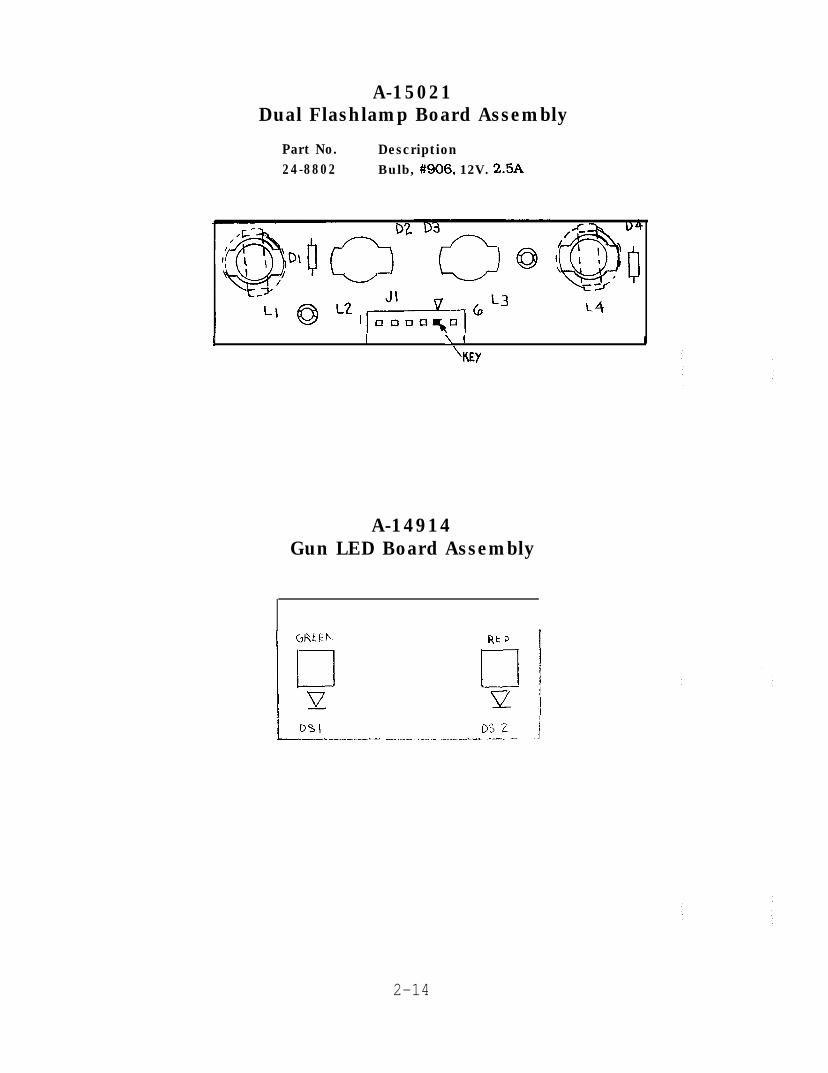
A-15021Dual Flashlamp Board Assembly
Part No. Description24-8802 Bulb, #906, 12V. 2.5A
I I \ I 1
'KEY
A-14914Gun LED Board Assembly
DS2 ,j__-_____,I--..____. .__,_ .__.-.._- .__._ -
2-14
Terminator 2
E C T I
three
0 N
Schematics & Wiring
3-1
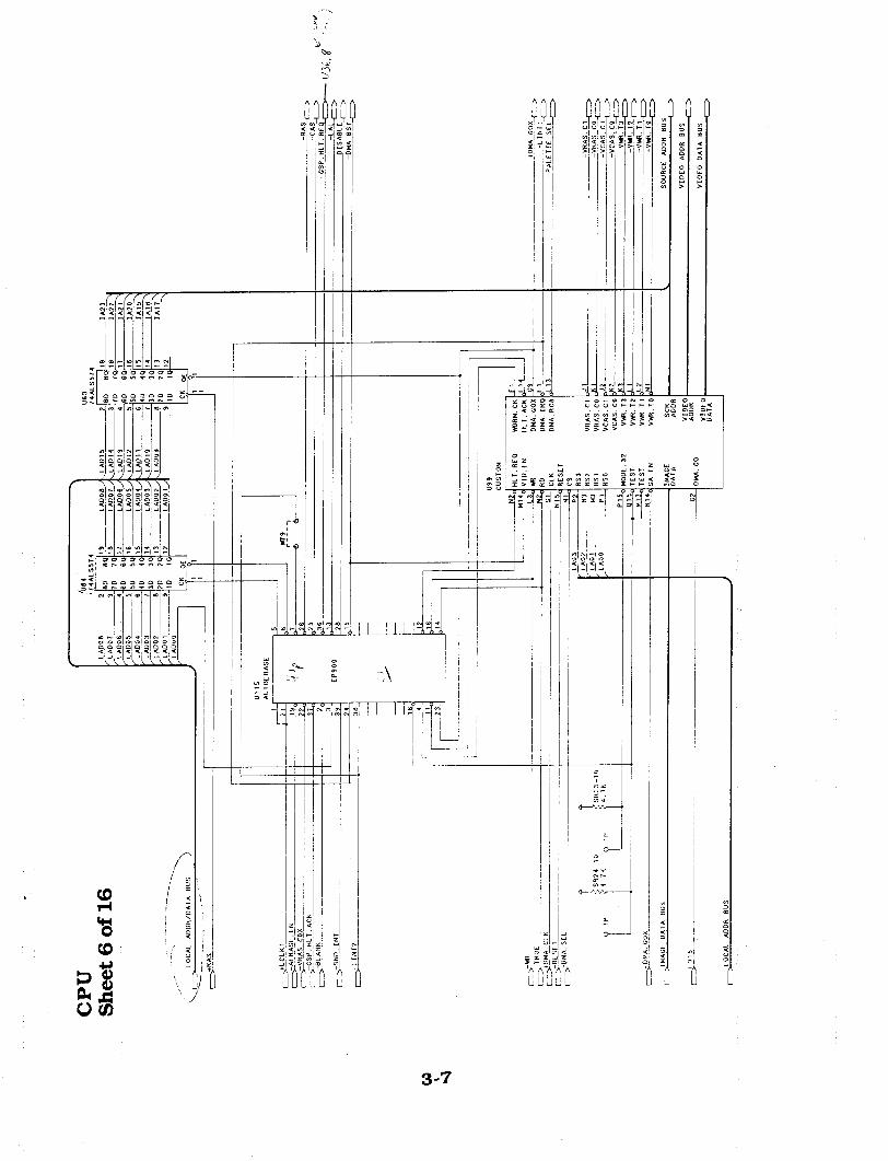
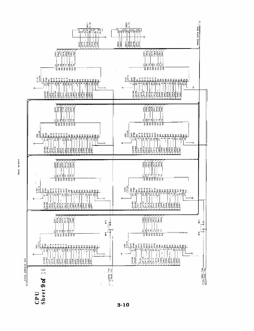
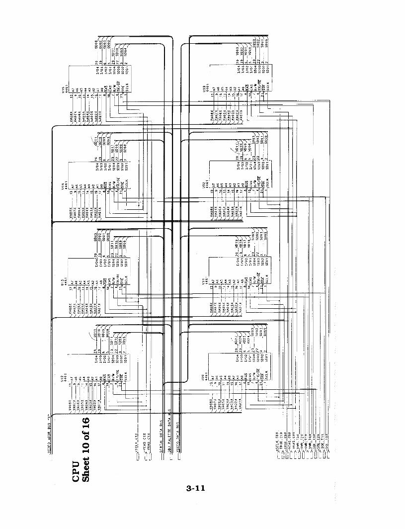
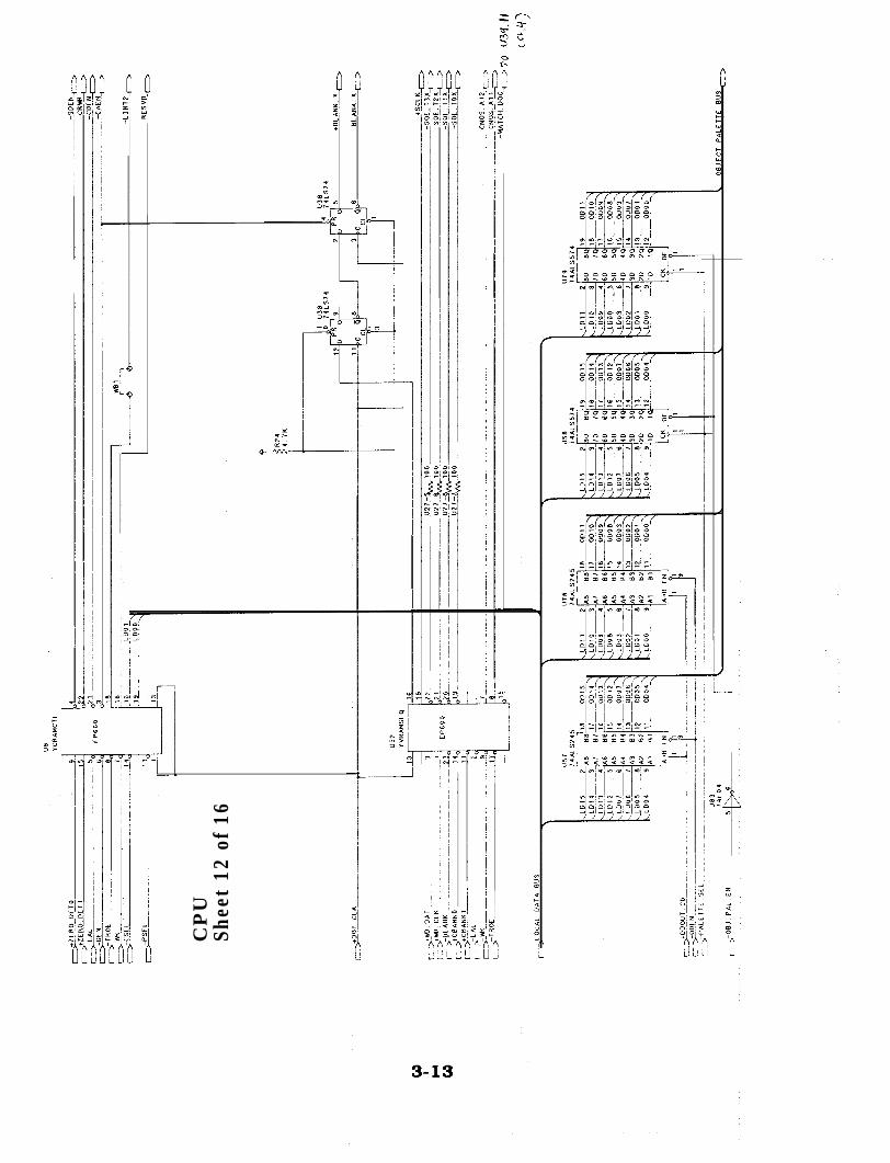
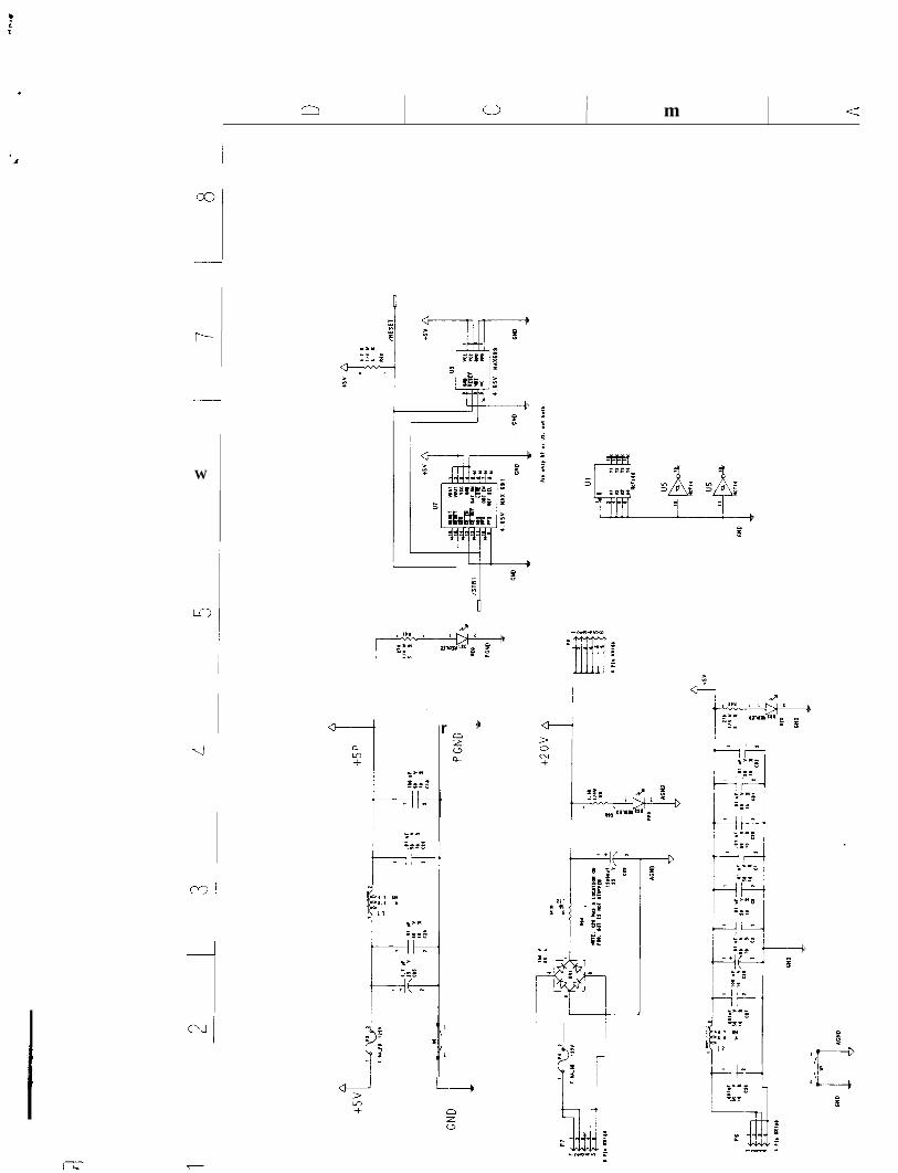
Sheetlof16
‘r‘/
/ i
,I
I ..-“8
3


/!
-
r+ j#----- II I
3-4

CP
U
2_
31
_ 1I !\


1
iill I/j_ osm D _ y1 *,,I& * _,4- - - -
r 6%80‘88ZX
T
J/ / // ,’ i , / / / i //,// I
3-9
IMAC
F
ADD
RES
S
BUS
D
\
CP
US
hee
t9o
f 16

-i
CP
USh
eet
11 o
f 16
I Iw
42
iv,3 L -t-
-
CP
USh
eet
12 o
f 16

sheet
13 o
f 16 II
II
SR
I4.
IK

sheet
14 o
f 16
I

Shee
t 15
of
16
->
_

CP
USh
eet
16 o
f 16
E R N A T t P I N 0 ” T
SOU
ND
P
OH
ER
,SP
E*K
EI
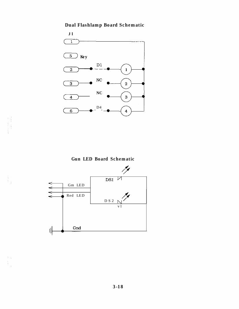
Dual Flashlamp Board Schematic
J l
(Ij
(5) Key
NC( 4) 3
. *r-g--i( 62-------*D4
- - 4
Gun LED Board Schematic
/
DSl ui Gm LED<<< 4) Red LED
D S 2 1\1v l
3-18
LT.
n / m j 6

i
In 0 m
I /:‘.P
\t- .
f 1;;
.ZZ’
f:
F e2-. .:21
.I
* iY

r
I
Ii

I In 0 m a:,
r
J
-
-
-
-
/ i j

mNc;,
co
r- r--
r
I -i
I
\.
--
8

Ii-d--4
/I----_i
i
m a
--.
r-
-7
W
i-I
r
I
i
i
.ine
on
Rib
bon
Cab
les
mus
t go
lo
Pin
-1
on b
oth
bo
ards
.C
able
s m
av n
eed
lo b
e tw
iste
d l
o a
ccom
dash
this
.
I I IL_------_J
Co
il L
amp
Dri
ver
Bo
ard
Op
tio
nsl
Coin
s 3
4 ’
EC
A C
dn
Dew
,np
u;a
.&
” c
orn
44
B,k
G
nd
see
Contr
ol
Pan
elW
irin
g
Dia
gra
mo
n N
ext
pag
e
--
TO
Conl
rol
Pa
ll.31
Lam
p 3
bm
p4
zl
L.rn
P 7
L.m
p 8
8
--
3-2
7

Control Panel Wiring DiagramPlayer 1 and Player 2 Gun Assemblies bye identical Wirlng.
Gry-Blu-.l
YeCVb 2
Yel-Gry 3
Blu-Wht 4
Blk 5
Gm-Blk 6
Gm-Ora I Fn7 7
Gm-Red .9
Blk.Yel 9
KM 1c
IGm-YeI LEDO 1 1
Gm-Gry coil li
l---------_~_____----______-
Player 1 Gun Control Panel:
I
KBY
Blk.Gm Gm LED LED 2
( 12 Gm-Blu Coil 1
I
I
!II Player 2 Gun
KW
BkGm GmLEDLED4 *f;;\
Gm-61~ coil 2
Player 1Start
Player 2Start