time crisis 2 dx - ohwow-arcade.com
TRANSCRIPT

Time Crisis 2 DX
The real product you have received may differ sl ightly from what is i l lustrated.
. Be sure to read this Operation Manual before using your machine to ensure safe operation.
11 for quick access.Ia
l Store the Operation Manual in a safe place together with the Projector Adjustment Manual

lNTRODlJCT/ON
INTRODUCTION
Thank you very much for purchasing Namco’s Time Crisis 7. DX (“this machine”).
This Operation Manual describes:- how to run, install, transport, move, maintain, and scrap this machine safely- how to run this machine correctly while making full use of its functions- how to ensure safety for players and observers.
Whom to contact when you need information about this machine and its repairs- For information about this machine and its repairs, contact your dealer.

1. SAFETY PRECAUTIONS
1. SAFETY PRECAUTIONSBe sure to read these instructions to ensure safe use.
Instructions to the owner:
If you wish to commission another party to run, install, transport, move, maintain, or scrap this ma-chine, please instruct that party to read and observe all instructions for the particular action to beconducred.
l-l Magnitudes of risk
For this machine and this Operation Manual, safety precautions and property damages are classified aslisted below according to the magnitude of the particular risk.
Qf DANGER: Failure to avoid the risk will most probably result in death or serious injury.
Qt WARNING: Failure to avoid the risk may result in death or serious injury.
Q1 CAUTION: Failure to avoid the risk may result in minor injury or property damage.
Functional notes not related to safety are marked with the following label:
m Notes related to a function and protection of the product
1-2 Definition of the term “technician”
This Operation Manual is designed for arcade game shop personnel. However, those sections marked‘To be conducted by a technician only” in the table of contents are written for technicians. Such tasksmust therefore be conducted by a technician only.
Technician:
A person engaged in machine design, manufacture, inspection, or maintenance for a manufacturerof amusement equipment, or a person who has technical knowledge related to electricity, electron-ics, and mechanical engineering at a level equal to or superior to that of graduates of industrialhigh school, and who engages routinely in maintaining (repairing) amusement equipment.
1

7. SAFETYPRECAUTIONS
1-3 Top-priority safety precautions
FADANGER. In adjusting the projector, do not touch anything other than the parts specified in the work procedure,Carelessly touchmg any part msrde the projector other than the parts specified may give you an electric
* The projector contains some parts that retain high heat and voltage after power-off.
WARNING
l Should any trouble occur, turn off the power and stop operating this machine immediately. Then do notforget to unplug the power cord. Running this machine with its trouble unsolved may cause a fire or otheraccident.
0 Keeping the inside of the projector dusty for a long time may cause a fire or breakdown. Consutt yourdealer for internal cleaning about once a year after purchase.
l In scrapping this machine, do not remove the screen off the projector. The screen removed or the lenscontained in it may cause a fire or get you lost your sight or burned.
l Dust accumulated on the power plug may cause a fire. Conduct a regular check and remove dust.
. Insert the power plug into the service outlet securely all the way. Poor contact may cause heat, resulting ina fire or getting you burned.
. A breakdown of the power cord may cause a fire, an electric shock, or leakage. Observe the followinginstruct ions:l Do not make the cord come close to a heating device.- Do not twist the cord.. Do not bend the cord forcefully.- Do not modify i t .l Do not bundle it.l Do not pull it. (To pull out the power plug, do not pull the cord. Always hold the power plug to pull it out.)l Do not place anything on it.l Do not get it caught by this machine, other product, or wall.l Do not do anything else that may damage the power cord.
l Do not wet the power cord or power plug wrth water. That might cause an electric shock or leakage.
. Do not touch the power plug with a wet hand. That might give you an electric shock.
. This machine has a power capacity of 1lOV AC, 8.5A (220V AC, 4.1A). Always use indoor wiring thatconforms to this machine’s power specifications. Otherwise a tire or an electric shock might result.
. Run this machine with a supply voltage in the ll O-12OV AC (or 220-240V AC) range. Using this machine atany voltage outside the specified range might cause a fire or electric shock. To ensure this machine runsunder its best condition. use a rated voltage whenever possible.
l Use specified brands of consumables and service parts (including screws). To order any part, contact yourdealer.
. Do not remodel this machine without permission. Do not carry out any task not covered in this OperationManual. Unauthorized remodeling may result in an unexpected risk.
l In re-sell ing this machine, always attach this Operation Manual and the Projector Adjustment Manual to thismachine.
2

1. SAFETY PRECAUTIONS
1-4 Description of the “warning label” attached to this machine
7* WARN’NG0 The warning label” describes important safety precautions. Obsewe the fol lowing:
l Be sure to install the machine so that the “warning label” attached should be read well under appropriateil lumination. Do not let this label get hidden by another machine or other object.
l Do not remove or modify the ‘kraming label.”l When the “warning label” is dirty or damaged, replace it with a new Xvaming label.” To order an addi-
tional %aming label,” contact your dealer.
Only. qwlM sarvia hchnlcimhaIlwedtoopath#&xw.ma pm3 Insida contahu btlulL U High-voltage parts refer to certain partsHIGH VOLTAGE&sun to unplug tha AC power
inside the projector.
bdwmopnlngfhedwr.Warning sticker (high voltage)Part # 461-371
3

T. SAFETY PRECAUTlONS

CONTENTS
CONTENTS
1. SAFETY PRECAUTIONS ...................................................................................................................
f - 1 Magnitudes of risk .........................................................................................................................
l -2 Definition of the term “technician” .................................................................................................
1 - 3 Top-prior i ty safety precautions.. ....................................................................................................
l -4 Description of the “warning label” attached to this machine .........................................................
CONTENTS . . . . . . . . . . . . . . .._.............................. . . . . . . . . . . . . . . . . . . . . . . . . . . . . . . . . . . . . . . . . . . . . . . . . . . . . . . . . . . . . . . . . ..I..... . . . . . . . . . . . . . . . . . . *a . . . . 4
2 . SPECIFICATIONS . . . ..____.............,.................,,...........................,......................................................... 8
3 . C H E C K I N G THE PACKAGE CONTENTS . . . . . . . . . . . . . . . . . . . . . . . . . . . . . . . . . . . . . . . . . . . . . . . . . . . . . . . . . . . . . . . . . . . . . . . . . . . . . . . . . . . . . . . . . . . 1 2
4 . COMPONENTS (NAME OF EACH COMPONENT) . . . . . . . ..__................................................................. 1 4
5 . INSTALLATION ................................................................................................................................... 1 5
5-l Conditions for installation .............................................................................................................. 1 5
5-1-l Locations t o a v o i d installing.. ............................................................................................. 1 5
5-l-2 P l a y zone a s installed ........................................................................................................ 1 6
5-2 Required dimensions of carry-in passage (such as doors and corridors). .................................... 1 7
5-Z-l Dividing the projector (L) and (R) Assys ............................................................................ 18
5-3 Assembly ...................................................................................................................................... 20
5-3-l Removing the joint Assy and pedal Assy ........................................................................... 20
5-3-2 Connecting the projector (L) and (R) Assys to the joint Assy ............................................ 22
5-3-3 Install ing the signboard Assy ............................................................................................. 2 5
5-3-4 Connecting the tower Assy ................................................................................................ 2 6
5-3-5 Install ing the pedal Assy .................................................................................................... 27
5-4 Connecting the power cord and the ground.. ................................................................................ 26
(1) With a 3P service outlet ......................................................................................................... 20
(2) With a 2P service outlet ......................................................................................................... 2 8
(3) If the 2P service outlet has no ground terminal ..................................................................... 2 9
5-5 Adjusting the projectors ................................................................................................................ 3 0
6. MOVING AND TRANSPORTING ........................................................................................................ 3 1
6-l Moving (on the floor) ..................................................................................................................... 3 1
6-2 Transporting .................................................................................................................................. 3 2
6-2-l Dividing .............................................................................................................................. 3 2
6-2-2 Manual carrying (up or down the stai rs , for example) ............ . .......................................... 35
6-2-3 Loading and unloading a vehicle or something similar.. .................................................... 36
6-2-4 Trucking ............................................................................................................................. 37
5
CONTENTS
7 . OPERATING THIS MACHINE ............................................................................................................. 3 8
7-l Pm-service c h e c k ......................................................................................................................... 3 9
7- l - l Appearance check.. ........................................................................................................... 39
7-l - 2 Operation c h e c k ................................................................................................................ 39
7-I-3 Periodic c h e c k ................................................................................................................... 3 9
7-2 How t o p l a y ................................................................................................................................... 40
7-2-i How t o control.. .................................................................................................................. 4 0
7-2-2 Modes ................................................................................................................................ 40
7-2-3 R u l e s ................................................................................................................................. 4 0
7-3 Adjustment.. .................................................................................................................................. 4 1
7-3-l Turn o n t h e power switch.. ................................................................................................. 4 1
7-3-2 Adjustment switches ........................................................................................................... 4 1
7-4 Test mode ..................................................................................................................................... 43
7-4-l Description of the menu screen ......................................................................................... 43
7-4-2 Setting a game fee and free play (COIN OPTIONS) ......................................................... 44
7-d-3 Setting the type of game (GAME OPTIONS) .................................................................... 4 5
7-4-4 I/O tests for switches (I/O TEST) ....................................................................................... 4 6
7-4-5 MONITOR TEST.. .............................................................................................................. 5 0
7-4-6 SOUND TEST. ................................................................................................................... 5 1
7-4-7 Displaying and initializing game d a t a (ADS DATA). ........................................................... 5 27-4-8 OTHERS.. .......................................................................................................................... 53
7-5 Setting t h e gun aiming ( G U N INIT IAL IZE) .................................................................................... 54
8 . MAINTENANCE .................................................................................................................................. 57
8-l Maintenance and inspection ......................................................................................................... 57
8- l - l Greasing t h e plunger of t h e pedal Assy. . ........................................................................... 5 8
8-l-2 Checking the plunger of the pedal Assy for wear and tear.. .............................................. 6 0
8-l-3 Cleaning the projector screen.. .......................................................................................... 6 0
8-2 Troubleshooting ............................................................................................................................ 6 1
8-2-l General .............................................................................................................................. 6 1
8-2-2 Projector (L) and (R) Assys ............................................................................................... 6 2
6-2-3 Signboard Assy .................................................................................................................. 6 2
8-2-4 Tower Assy ........................................................................................................................ 6 2
8-2-5 Pedal Assy ......................................................................................................................... 6 2
8-2-6 G u n A s s y ........................................................................................................................... 63
8-3 Disassembling, reassembling and replacing the Assys and parts ................................................ 64
8-3-l Projector (L) and (R) Assys ............................................................................................... 64
(1) Detaching and reattaching the rear cover .................................................................. 646 5(2) Replacing t h e projector with a new one .....................................................................
(3) Detaching and reattaching the rack Assy ................................................................... 6 6
(4) Replacing the game PC board with a new one .......................................................... 67
8-3-2 Signboard Assy .................................................................................................................. 6 9
(I) Replacing the fluorescent lamp and glow lamp with new ones .................................. 6 9
8-3-3 Tower Assy ........................................................................................................................ 7 0
(1) Replacing t h e I/O P C board with a new one .............................................................. 70
6

CONTENTS
8-3-4 Pedal Assy ......................................................................................................................... 7 2
(1) Replacing t h e microswi tch wi th a new one.. ............................................................... 7 2
(2) Replacing the plunger with a new one ....................................................................... 73
8-3-5 Gun Assy ........................................................................................................................... 74
(1) Replacing t h e gun A s s y with a new one ..................................................................... 74
(2) How to open the gun slide .......................................................................................... 7 5
(3) How to open the gun cover ........................................................................................ 76
(4) Replacing t h e solenoid with a new one ...................................................................... 77
(5) Replacing the microswitch with a new one ................................................................. 78
(6) Replacing the tube with a new one ............................................................................ 78
9. DISCARD .____.....,...............,.......,..........,........,..........................,........................................................... i’g
1 0 . PARTS LIST ....................................................................................................................................... a0
10-l Front Assy .................................................................................................................................. 80
IO-2 Projector (L) Assy ...................................................................................................................... a 2
lo-3 Projector (R) Assy ...................................................................................................................... 84
lo-4 Signboard Assy .......................................................................................................................... 86lo-5 Joint Assy ................................................................................................................................... 88
10-6 Control base Assy ...................................................................................................................... 90
lo-7 Rack Assy ............................................................................................................................... 92. . .
1 O-8 Cord box Assy ............................................................................................................................ 94
1 O-9 Tower Assy ................................................................................................................................. 96
10-10 pedal Assy ................................................................................................................................ 98
lo-11 GunAssy.. ............................................................................... .................................................. 100
10-12 Coin Assy .................................................................................................................................. 1 0 2
11. WIRING DIAGRAM ............................................................................................................................. 1 0 5
projector(L), (R)Assy.. ........................................................................................................................ 105Tower Assy ................................................................................................................ ........................... 105
7

2. SPEClFlCATlONS
2. SPECIFICATIONS(1) Rated power supply: 1 IOV-12OV AC or 22OV-240V AC (50/60 Hz)(2) Maximum power consumption: 670W (for 11OV AC power supply)
680W (for 220V AC power supply)(3) Maximum current consumption: (8SA (for IIOV AC power supply)
(4.1A(for 220V AC power supply)(4) Cash box capacity: approx. 300,000 yen (3,000 IOO-yen coins)(5) 50” rear projector X 2(6) Dimensions
@ As installed: 2,320 (W) x 1,930 (D) x 2,310 (H) mm
2,320
@ As dividedProjector (L) AssyProjector(R) AssyTower AssySignboard AssyJoint AssyPedal Assy
1,16O(W)x720x(D)x1,840(H)mm1,16O(W)x720x(D)x1,84O(H)mm1,420(W)x720x(D)x I,llO(H)mm1,620 (W) x 570 x (D) x 490 (H) mm450 (W) x 500 x(D) x 160 (H) mm250 (w) x 250 x (D) x 160 (H) mm
8

2 . SPEC/NCAT/OA’S
Projector (L) Assy
720-1
Projector (R) Assy
t1,160
1
-
Ea
-
720
9

2. SPECIFICATIONS
Tower Assy
c 1,420
Signboard Assy
Joint Assy
Pedal Assy
* a
I
* .
-1
1 4501
c 7 2 0
I:_ b1
1 0
2. SPEC~~CATDNS
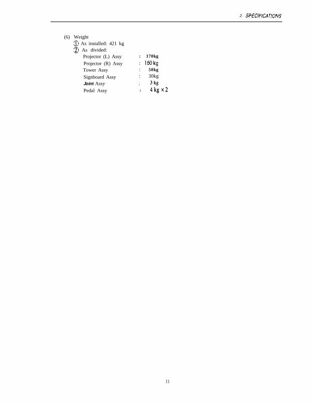
(6) Weight@ As installed: 421 kg0 As divided:
Projector (L) AssyProjector (R) AssyTower AssySignboard AssyJoint AssyPedal Assy
: 170kg
: 160kg: 50kg: 30kg
: 3kg: 4kgx2
11

3. CHECKING THE PACKAGE CONTENTS
3. CHECKING THE PACKAGE CONTENTSWhen packed and shipped, this machine consists of the following:
l Be sure to check that you have received all packages indicated below.0 If you find any component missing, contact your dealer.
o Projector(L) Assy: 1 unit 0 Proiector (RI Assv: 1 unit
l Tower Assy: 1 unit
Joint Aesy
Pedal Assy

3. CHECKING THE PACKAGE CONTENTS
0 Signboard Assy: 1 pee
0 List of accessories

4. COMPONENTS (name of each component)
4. COMPONENTS (name of each component)
Coin Assy
-qggy Tower Assy
Powq swi tch\
\Ground terminal
\ Power cord
Warning sticker(high voltage)
Caution sticker
Rack Assy
1 4

5. INSTALLATION
INSTALLATION
I f WARNINGQ
. Install the components according to the descriptions and specified procedures in this Operation Manual(see P-15, 5. Installation). Failure to follow any procedure might result in a fire, electric shock, injury, orbreakdown.
. Insert the power plug into the service outlet securely all the way home. Poor contact may cause heat,resulting in a fire or getting you burned.
l Be sure to ground the machine. Failure to ground may cause an electric shock in the case of leakage.(See P-28,5-4 ‘How to Connect the Power Cord and Ground.“)
. When installing this machine, always fix 1 with the level adjustors. Failure to fix it may cause an
accident or injury.
5-l Conditions for installation
the vent holes with a wall or other object either. Failure to observe these instructions may heat up theinside of this machine, resufting in a fire or breakdown.
5-l-i Locations to avoid installing
yA W A R N I N G - ,
. This machine is designed for indoor use. Never install this machine outdoors or at any of the followinglocations:l Locations exposed to direct sunlightl Locations subjected to rain or water leakagel Damp placesl Dusty placesl Close to a heating instrumentl Hot placesl Extremely cold placesl Places where dew may develop due to temperature differencesl Places where this machine may become an obstacle in disaster prevention (such as an emergency
exit) and places where a fire extinguisher or similar equipment is placedl Unstable or vibrating places
,
1 5

5 . 1NSJALLAJiON
5-l-2 Play zone as installed
r*wARN’NGl Set a play zone as illustrated in the figure below to prevent customers leaving this machine from gettinginto contact with observers and passers-by.
0 This machine needs be at least 2m 35cm from the ceiling.0 Allow for a clearance of at least 5Ocm between the rear of this machine and the wall or
other machines in order to facilitate the removal of the rack Assy and PC board formaintenance.
5Oom
Approx. 3m 35cm or more
50cm
1 6

5. INSTALLATION
5-2 Required dimensions of carry-in passage (such as doors andcorridors)
This machine is divided to ship. The divisions have the dimensions mentioned below.l Projector (L) Assy : 1,160(W)x720(D)x 1,84O(H)mm
W e i g h t : 1 7 0 k gl Projector(R) Assy : 1,16O(W)x720(D)x1,840(H)mm
(Incl. joint Assy and pedal Assy) Weight: 170kgl Tower Assy : 1,420(W)x720(D)x1,110(H)mm
W e i g h t : 5 0 k gl Signboard Assy : 1,620 (W) x 570 (0) x 490 (H) mm
W e i g h t : 3 0 k gThe carry-in passage must therefore be large enough to be equal to or exceed the dimensions listedabove.Depending on the conditions of the access door, the projector (L) and (R) Assys can be divided asindicated below.l Projector : 1,16O(W)x620(D)x1,340(H)mm
Weight: IOOkgl Projector base (L) : 1,16O(W)x720(D)x6OO(H)mm
Weight: 70kgl Projector base (R) : 1,16O(W)x720(D)x600(H)mm
W e i g h t : 6 0 k g
For the procedure of dividing these components, see P-18,5-2-1 “Dividing the Projector (L) and (R)Assys -To Be Conducted by a Technician Only-.”
Signboard Assy
Tower Aaay /
Projector (R) Aaay
is
t@
/
2720
1 , 8 4 0
i
7
(The projector (L) Assy haa the same dimens!ans.)

5. INSJALUJION
5-2-l Dividing the projector (L) and (R) Assys
-To be conducted by a technician only -
0 This task need not be conducted if the ceiling above the carry-in passage and the opening of theaccess door are high enough.
Q1 WARNING
. Each projector weighs about 100kg. Removing the projectors must be conducted by at least five peopleto avoid accidents.
0 Remove the four Phillips tmss screws (M5 x 30) from the front of each projector Assy andremove the front cover.
q Remove the two connectors connecting the projector to the projector base, then remove the twohexagon bolts (Ml0 x 130). two spring washers (MlO), and two square washers (large, MIO).
Phillips truss screw(M5 x 30)
Projector base
Hexagon bolt (Ml0 x 130) ’
1 8

5 . INSTALL4TION
q Remove the two Phillips truss screws (M5 ⌧ 30) from the rear of the projector and remove thesmall lid.
q Remove the two Phillips truss screws (M5 x 30), unlock the projector, and open the rear cover.(The projector (R) Assy is not locked.)
q Remove the two hexagon bolts (MI0 ⌧ l30), two spring washers (MIO), and two squarewashers (large, MIO) from the rear.
Projector Assy (rear)Small l id
Square washer ( large, MlO)
screw (M5 x 30)
q Lift the projector by about IOcm from the projector base, then move it forwards or backwardsand lower it slowly.
q For reassembly, follow the reverse order of the disassembly.
In placing the projector on the proj’ector base, check that the outside of the guides onboth sides of the top of the projector base meshes with the inside of the side plate ofthe projector.
1 9

5. INSTALLATION
5-3 Assembly
5-3-l Removing the joint Assy and pedal Assy
-To be conducted by a technician only -
q Remove the four flange sockets 018 x 20) from the rear of the projector(R) Assy and removethe joint Assy.% The four removed flange sockets (MS x 20) will be used for installing the joint Assy.
I, Flange socket
I wx20)
(R) Assy
H Remove the two Phillips buss screws (M5 x 30) from the rear of the projector(R) Assy anddetach the rear cover.
Rear cover
Phillips tmsa screw (M5 x 3
5. INSTALLATION
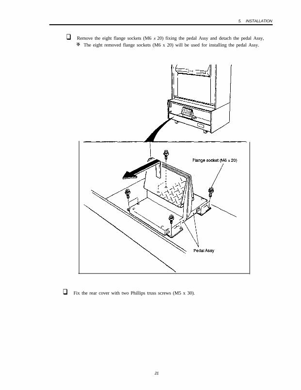
q Remove the eight flange sockets (M6 x 20) fixing the pedal Assy and detach the pedal Assy,% The eight removed flange sockets (M6 x 20) will be used for installing the pedal Assy.
q Fix the rear cover with two Phillips truss screws (M5 x 30).
21

5 INSTALL4TION
5-3-2 Connecting the projector (L) and (R) Assys to the joint Assy
-To be conducted by a technician only -
0 Install the spacer on the projector(R) Assy with four Phillips self-tapping binding screws (4mmdia x 16) furnished with this machine
Phillips sell-tapping bindingscrew (4mm d i a x 16)
\
Space! Pmjector (R) Assy
q Arrange the projector (L) and (R) Assys according to P- 15.5-I “Conditions for Installation.”Then lower the four level adjustors until the bottom of the casters are about 5mm from floorlevel (so that they can turn freely).
2 2
5. INSTALLATION
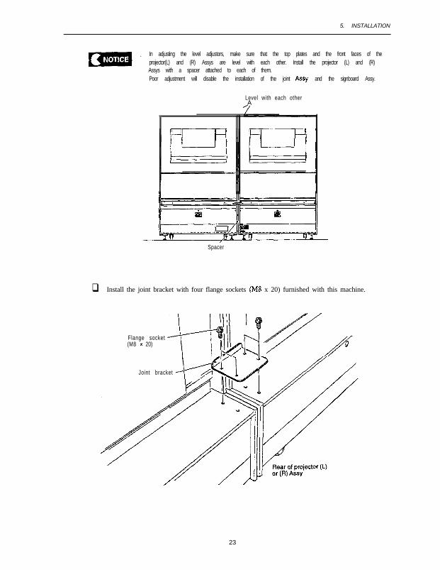
. In adjusting the level adjustors, make sure that the top plates and the front faces of theprojector(L) and (R) Assys are level with each other. Install the projector (L) and (R)Assys with a spacer attached to each of them.Poor adjustment will disable the installation of the joint Assy and the signboard Assy.
Level with each otherA
Spacer
q Install the joint bracket with four flange sockets (M8 x 20) furnished with this machine.
Flange socket(M8 x 20)
Joint bracket
23

5. INSTALLATION
q Fit four flange sockets (MS x 40) furnished with this machine to the front face of the projector(L) and (R) Assys temporarily with a clearance of about 5mm.
Front face of theprojector (L) or(R) Assy
Flange socket (M8 x 40)
q Remove the four torque bolts (M5 x 12) from the joint Assy and detach the joint cover.q Install a joint to the projector(L) and (R) Assys and tighten the four flange sockets (MS x 40).
q Pull the harnesses out of the projector (L) and (R) Assys.q For detachment, follow the reverse order.
24

5. INSTALLATION
5-3-3 Installing the signboard Assy
-To be conducted by a technician only -
11 Insert and place the bottom of the signboard Assy on the signboard hook at the top of thepro jec to r (L) and (R) Assys.
q Fix the signboard with four hexagon bolts (with flat and spring washers, M6 X 30) and fourwashers C furnished with this machine.
a Remove the two torque bolts (M5 x 12) at the right of the rear signboard Assy and detach theconnector cover.
q Connect the connector of the signboard Assy to the projector.q Install the connector cover in its original position.
Signboard hook
Hexagon bolt (with f lat and
Signboard Assyspring washers, M6 x 30)
\
connector Washer C
I /
Connector cover
q For detachment, follow the reverse order.
25

5. INSTALLATION
5-3-4 Connecting the tower Assy
-To be conducted by a technician only -
0 Install the tower Assy fitting it to the joint.q Use the four flange sockets (M8 x 20) that fixed the joint Assy when this machine left the
factory (see P-20.5-3-1 0) to fix the tower Assy.q Pull the harness out of the tower Assy.
i ;-onyththe six connectors.IX t e arness with the cord clips at the bottom of the joint.
q Install the joint cover with four torque bolts (M5 x 12).q For detachment, follow the reverse order.
Torque
Cord clip

5. INSTALLATION
5-3-5 Installing the pedal Assy
-To be conducted by a technician only -
q Loosen the four flange sockets (M5 X 12) in the pedal Assy.
Pedal bracket
ge socket (M5 x 12)
q Connect the connector between the pedal Assy and the tower Assy. Then, using the four flangesockets (M6 x 20) that fastened the pedal Assy when this machine left the factory (see P-21, 5-3-1 q ), fasten the pedal Assy.
Flang(M6 x
Flange socket (M6 x 20)
q Press the pedal Assy against the floor and fasten the four flange sockets (M5 X 12). (Make surethat the pedal Assy does not lift above the floor.)
Flange socket (M5 x 12)
q Install the opposite side similarly.a For detachment, follow the reverse order.
27

5. INSTALLATION
5-4 Connecting the power cord and the ground
,- 1 W A R N I N GQ
. Be sure to install the ground conductor in either of the methods described below. Failure to install aground conductor may cause an electric shock in the caee of a leakage.(1) Ground the ground conductor with a 3P plug.(2) (If the ground conductor cannot be grounded with a 3P plug,) ground the ground conductor with a
3P-2P conversion plug.(3) (If the ground conductor cannot b e grounded with either a 3P plug or a 3P-2P conversion plug,)
ground the machine by connecting the grounding wire to the ground terminal of this machine.
(1) With a 3P service outlet
Simply insert the power plug.
Power plug
(2) With a 2P service outlet
Ground the ground conductor with the 3P-2P conversion plug furnished with this machine.
Power plug

5. INSTALLATION
(3) If the 2P service outlet has no ground terminal
Ground the machine by connecting the grounding wire to the ground terminal at the rear of theprojector(R) Assy. (No grounding wire is furnished with this machine.)
. Install the grounding wire as illustrated below.
Toothed washer (M4)Cup screw (M) (M4 x 10)
I

5. INSTALLATION
5-5 Adjusting the projectors
Qf DANGER
. In adjusting the projectors, do not touch anylhing other than the parts specified in the work procedure.Carelessly touching anything inside a projector other than the parts specified may give you an electricshock or get you burned.f The projectors contain some parts that retain high heat and voltage alter power-off.
The projectors may cause color displacement depending on vibrations that may occur during move-ment and on their orientation as installed. If such trouble occurs, perform adjustment according to theprocedure specified below. For the specific procedure for adjusting the projectors, see the ProjectorAdjus tmen t Manual .
. Failure to observe the adjustment procedure or touching any control other than thespecified ones may result in the particular control becoming unable to rehun to normal.
q Remove the front cover. (See P-18,5-2-1 “Dividing the Projector(L) and (R) Assys.“)
s Adjust the projectors according to the Projector Adjustment Manual.
q After the adjustment, install the front cover back in its earlier position.
30

6. MOVING AND TRANSPORTING
6. MOVING AND TRANSPORTING
/- 1 WARNINGQ. Do not leave this machine on a slope. Leaving it on a slope may result in the machine falling down or
causing an unexpected accident.. The tower Assy is not designed to be carried with a forklift. Do not use a forklift for moving and trans-
port ing this machine. Using a forklift may cause thus machine to fall down or cause an unexpectedaccident.
6-1 Moving (on the floor)
l If the projectors (L) and (R) Assys. signboard Assy, joint Assy, tower Assy, and pedalAssy are coupled together, be sure to divide this machine into assemblies whilereferr ing to P-32, 6-2-l “Dividing.”
l Before moving any assembly either over a short or a long distance, always retract thelevel adjustors of the projector (L) and (R) Assys all the way up. (Do not adjust the leveladjustors of the towsrAssy.)
l The projector(L) and (13) Assys are lm .%cm in overall height. Watch out for theheights of the door opening and ceiling of the corridor.
l Transport the assemblies carefully, keeping them undamaged.0 The molded parts are not so strong. Do not apply a strong force to any of them.l After moving or transporting, adjust the projector
How to cany the tower Assy
3 1

6. MOVING AND TRANSPORTING
6-2 Transporting
6-2- l Div iding
-To be conducted by a technician only -
q Remove the four flange sockets (M6 x 20) and one connector and detach the pedal Assy.(Do the same for the opposite side.)
q Remove the four torque bolts (M5 ⌧ 12). detach the joint cover, and remove the six connectors.
Torque bolt (M5 x 12)
3 2

6. MOVING AND TRANSPORTING
q Remove the four flange sockets (M8 ⌧ 20) and detach the tower Assy. After the detachment,house the hamess inside the tower Assy.
q Remove the two torque bolts (M5 x 12) at the right of the rear of the signboard Assy. Thendetach the connector cover.
q Remove the one connector from the signboard Assy, then install the connector cover back in itsplace.
q Remove the four hexagon bolts (with flat and spring washers, M6 x 30) and four washers C.q Remove the signboard Assy from the projector screen side.
Qf WARNING
l The signboard weighs about 30kg. At least two people and a sufficient working space are needed t0avoid accidents.
Signboard Assy
\
Hexagon bolt (with f lat andspring washers, M6 x 30)
Connector / Washer CConnector cover
Torque bolt (M5 x 12)

q
lil
6. MOVING AND TRANSPORTING
Remove the four flange sockets (MS x 40), then detach the joint. After the detachment, re-install the joint cover which you removed in step q .House the harness sticking out of the projector(L) and (R) Assys.
Torque bolt (M5 x 12)
Remove the four flange sockets (M8 x 20), then detach the joint bracket.Retract the level adjustors (four each) of the projector (L) and (R) Assys all the way up.
19 End of the dividing procedure

6. MOVING AND TRANSPORTlNG
6-2-2 Manual carrying (up or down the stairs, for example)
yn WARNING
0 Be sure to divide this machine into the projector (L) and (Pi) Assys. signboard Assy, tower Assy, and
pedal Assy. (See P-32. 6-2-i “Dividing.“)
Also, be sure to divide the projector(L) and (R) Assys into the projectors and projector bases (L) and
(R). (See P-16, 52-t “Dividing the Projector (L) and (R) Assys.“)
l Transporting any combination of assemblies without dividing them may result in an accident or injury.
. Manual carrying must always be conducted by the appropriate number oi people specified below. Any
attempt to carry any machinery by an insufficient number of people may result in an accident or injury.
l Projector (1 OOkg) : 5 people or more
l Projector base (L) (70kg) : 4 people or more
l Projector base (R) (60kg) : 4 people or more
l Signboard Assy (3Okg) : 2 people or more
l Tower Auy (5Okg) : 3 people or more
Projector (L) and (R) Assys
Tower Assy

6. MOVING AND TRANSPORTlNG
6-2-3 Loading and unloading a vehicle or something similar
,--A WARNING
. Be sure to divide this machine into the projector (L) and (R) Assys, joint Assy, signboard Assy, towerAssy, and pedal Assy. (See P-32, 6-2-I ‘Oividing.“)
0 The tower Assy is not designed to be transported with a forklift. 00 not use a forklift for moving ortransport ing this machine. Using a forkl i f t may cause this machine t o fall down or cause an unexpectedaccident.
0 Transport every component carefully while taking care not to damage it.0 The molded parts are not so strong. Do not apply a strong force to any of them.l Always retract the level adjustors all the way up.0 In lowering any component from a higher level, do not let it get shocked.
36

6. MOVING AND TRANSPORTING
6-2-4 Trucking
l Before trucking this mach ine , fasten ail components firmly enough to prevent any ofthem from moving due to truck speedup or slowdown.
. Always apply ropes at the positions specified below.l Sandwich pads made of Styrofoam or something similar between the load-carrying
platform and cabinets to protect the surfaces of this machine.l Make sure that no pad touches the projector screens.
Cloth or sponge pad
\
Rope or belt
/
Pad made of Styrofoamor something similar
3 7

7. OPERATING THLS MACHINE
7. OPERATING THIS MACHINE
Qt WARNING
. If any trouble should occur, turn off the power switch immediately and stop operating this machine.
Then be swe to unplug the power cord. Operating this machine with its trouble unsolved may cause afire or accident.
. Keeping the inside of the projectors dusty for a long time may cause a fire or breakdown. Consult your
dealer for inner cleaning about once a year after purchase.. Dust accumulated on the power plug may cause a fire. Therefore conduct a regular check and remove
dust.. Insert the power cord into the service outlet securely. Poor contact may heat up this machine, resulting
in a fire or getting you burned.. Always make sure that you have installed this machine according to the descriptions and specified
procedures given in this Operation Manual (see P-15, 5. ‘Installation’), before operating this machine.Improper installation may cause a fire, electric shock, injury, breakdown, or other inconvenience.
. The warning label indicates important safety precautions. Observe the following:l The warning labels attached to this machine should be read well, therefore, you must take care the
appropriate place to be installed and appropriate illumination and the soils on them. Do not let thewarning label get hidden by another game machine or other object.
l Do not detach or modify the warning label.l If the warning label gets considerably dirty or damaged, replace it with a new one. To order a new
warning label, contact your dealer.

7. OPERATING THE MACHINE
7-1 Pre-service check
Before beginning your service, check the items described below. If any trouble is found, take appropri-ate actions according to P-6 1, S-Z “Troubleshooting.”
7-l-l Appearance check
,.m.e--------- A WARNING
. Check the points listed below before operating this machine. These checks are required to avoidaccidents and injury.l Is the warning label legible enough?l Are all level adjustors fixed?l Is there a sufficient clearance around this machine? (See P-15, 5-1 “Conditions for Installation.“)l Is the gun tube fastened at both ends? Is it damage-free?l Are the gun screws fastened?l Are the tower Assy and joint Assy fastened together!- Are the pedal Assy and tower Assy fastened together?
7-l-2 Operation check
0 Checking the sound
q Checking the fluorescent lamps
q Checking the image
To check the items listed below, press the service switch and play a game. (See P-41,7-3-2 “Adjust-ment Switches.“)
• I Checking the gun for response
H Checking the pedal effect
7-l-3 Periodic check
Clean the gun lens every day to keep it precise.* Wipe off dirt gently with a soft cloth.
3 9

7. OPERATING THIS MACHINE
7-2 How to play
This machine provides gun shooting games where players use a pedal to hide behind an object toavoid an enemy attack, then get out from behind the object with their own timing to attack theenemy.
7-2-l How to control
1. Step on the pedal = attack position: At this position, you can shoot the enemy. You are alsosubject to an enemy attack.
2 . Release the pedal = defence position: At this position, you are hidden behind an object. You arenot subject to an enemy attack. Releasing the pedal recharges the gun.
7-2-2 Modes
1. Link play mode: This mode is for two-player cooperative plays. An additional player can jointhe game after it has started.
2. Solo play mode: This mode is for single-player plays. No one can join the game once it hasstarted.
* Modes are selected on the Mode Selection Screen immediately after you insert a coin.
7-2-3 Rules
1 . Every time you get an enemy attack, you lose a life. You also lose a life when your remainingtime reaches zero. The remaining time is recovered when you have destroyed all your enemiesappeared or you have received an enemy attack. The game is over when you have zero lives left.
2 . A player’s achievement is assessed by score. The higher the score, the higher achievement.
Demonstration video clips between games can be skipped by aiming and shooting the gun at thescreen.
4 0

7. OPERATING THIS MACH,Ni
7-3 Adjustment
7-3-l Turn on the power switch.
When you are through with P-15, 5. “Installation, “turn on the power switch at the bottom right of
the rear of the projector (R) Assy.
Power switch
7-3-2 Adjustment switches
Open the service door of the coin Assy, and you will find the adjustment switches.
Service door\
(c) Select switch:Trlt this lever upwards or
(a) Service switch downwards to choose an
I\ i tem in the,test mode
(b) Test swkh(d) Enter switch:Choose an item with the selactswitch and finaliia and executeit with the enter switch.
4 1

7. OPERATING THlS MACHINE
(a) Service switch (red)
Press this switch to increase the credit count without activating the coin counter.(b) Test switch
Turn this switch on to enter the test pode.In the test mode, you can change game fees and other parameters and conduct various tests.(See P-43,7-4 “Test Mode.“)
(c) Select switchTilt this switch upwards or downwards to choose an item in the test mode.
(d) Enter switch (green)After choosing an item with the select switch, press this switch to finalize and execute thatitem.
l Unless slowly and securely pressed, the service switch may not get activated.
4 2

7. OPERATING TH1.S MACHINE
7-4 Test mode
7-4-i Description of the menu screen
q Unlock the service door with a key furnished with this machine, then turn on the test switch.The screen displays MENU.
r-MENU
COIN OPTIONSOAMg OPTIONS
LINK MALFUNCTION 1 2 3
The internal battery's dead.SELECT SW:CHOOSE
- Sets a game fee (see P-44,7-4-2).- Specifies the type of game (see P-45, 7-4-3).- Tests the switches and guns (see P-46,7-4-4).- Adjusts the monitor (see P-50, 7-4-5).- Controls the sound volume of the speakers (see P-51, 7-4-6).- Displays and initializes game data (see P-52. 7-4-7).- Initializes the backup memory (see P-53, 7-4-E).
- (4- (b) Do not appear when normal.- Cc)
Menu screen
q Tilt the select switch upwards or downwards to choose an item. The selected option blinks.
q Press the enter switch to determine an option.
q When the adjustment is over, select EXIT and press the enter switch. You go back to theMENU screen.
q When all adjustments are over, turn off the test switch. You then go back to the game screen.
If this machine breaks down or is in other trouble, (a), (b), and (c) display error messages.
(a) Error messages related to link play
* A message appears when the link play is defective. The game does not function normallywhile the error is on. The number at the right of the message represents the type of error.
l When “1” or “2” is displayed, a board (either the MAIN (1) or the MSPM game PC board)may be defective. (See P-67, 8-3-l (4) “Exchanging Game PC Boards.“) Contact your de&r.
l If ‘3” is displayed, the software version used on the right-hand board and that on the left-hand one do not match. Contact your dealer.
(b) Error messages related to difficulty setting
9 A message appears when the difficulty setting for the test mode on the right-hand side nnlthat for the left-hand one do not match. The game does not function normally while thy -1 “oris on. Enter the GAME OPTIONS in the right- and left-hand test modes and make the,difficulty settings match.
43

7. OPERATING THlS MACHINE
(c) Low-battery displayl When the battery level is low, a message appears. You must have the battery on the MAIN
(1) game PC board replaced with a new one. Contact your dealer.
7-4-2 Setting a game fee and free play (COIN OPTIONS)
Here you set a game fee and free play parameters.
11 While on the MENU screen, select COIN OPTIONS and press the enter switch. The COINOPTIONS screen will appear
COIN OPTIONS
[DEFAULT IN GREEN1
OAVDZ COST 4 COINS 1 CREDIT - - (a)CONTINUE COST 1 COINS 1 CREDIT - - (‘3
PKSE PLAY
EXIT
OFF - (c)
SELECT SW:CHOOSE ENTER SW:ENTER
COIN OPTIONS screen
option Description Factory sett ing
(a) Setting a game fee Coins required for one game: 1-9 coins -
(b) Setting a continue play fee Coins required for continue play: l-9 coins -
(c) Sett ing free plays OFF (No) OFFO N (Yes)
COIN OPTIONS settings table
q Use the select switch to choose the option you wish to change. The selected option blinks.q Press the enter switch and determine an option you wish to change.
q After determining the option, use the select switch to change the contents of the option.
q After changing the contents of the option, press the select switch to go back to option selection.
q Select EXIT and press the enter switch to go back to the MENU screen.
* When the free play setting is on, stepping on the pedal starts a game.

7. OPERATING THIS MACH/NE
7-4-3 Setting the type of game (GAME OPTIONS)
Here you set the type of game.
q While on the MENU screen. seIect GAME OPTIONS and press the enter switch. The GAMEOPTIONS screen will then appear.
GAME OPTIONS[DEFAULT IN GREEN]
P L A Y E R ’ S LIFE 4DIFFICULTYA-CT SOUND O NIfI-SCORE INIT N O
EXIT
SELECT SW:CHOOSE ENTER SW:ENTER
GAME OPTIONS screen
I Odkm Descrintion Factory setting
(a) Setting player l ives Lives of the player at the start of the game 41 to 9
(b) Dif f icul ty A (VERY EASY)S (EASY)C (MEDIUM) C (MEDIUM)D (HARD)E (VERYHARD)
(c) Sening the sound volume O Nat the attract mode OFF
(with sound)(without sound)
O N
(d) Initializing the high score NO (not to initialize)
I
N OYES (initialize) I
Table of GAME OPTIONS settings
H With the select switch, choose an option which you wish to change. The selected option blinks.
q Press the enter switch to determine an option you wish to change.
q After determining the option, use the select switch to change the contents of the option.
g After changing the contents of the option, press the enter switch to go back to option selection.
q Select EXIT dan press the enter switch to go back to the MENU screen.
* The game will not function normally unless the difftculty setting in (b) in the left-hand mode
matches that for the right-hand mode. Always match the diff%ulty settings for the left- andright-hand modes.
45

7, OPERATING THIS MACHINE
7-4-4 I/O tests for switches (I/O TEST)
Conduct I/O tests on the switches.
q While on the MENU screen, select I/O TEST and press the enter switch. The I/O TEST screenwill then appear
rI/O TEST
DIP 4 12345678 [ON/OFF1 -LINK ON 2
I/O PCB CHFSKGUN INITIALIZESWITCH TESTSOLENOID TEST
EXIT
SELECT SW:CHOOSE ENTER SW:ENTERc
l/O TEST screen
- (a)- (b)
- (C)- Cd)- 69- (0
q With the select switch, choose an option you wish to execute. The selected option blinks.
q Press the enter switch to go back to the test screen for the blinking option.
q Select EXIT dan press the enter switch to go back to the MENU screen.
(a) Status of the DIP switches
l This displays the starus of the DIP switches on the game PC board. The switches of thenumbers in red are on. (They are all factory-configured to be off.)
l All of them are normally used in the off status.
(b) Communication check
‘* This represents the communications status.
Display 1 Communication status 1
mlWhen unidentified data is received
Table of communication check settings
33 If the screen displays LINK OFF or LINK NG, the game will not function normally. The board(game PC board) may be defective. Contact your dealer.. When this machine is to be run with one of the game PC boards for repair or other purposes.
it is to be in the solo play mode. (See P-40,7-2-2 “Modes.“)
46
7. OPERATING Th’LS MACHINE
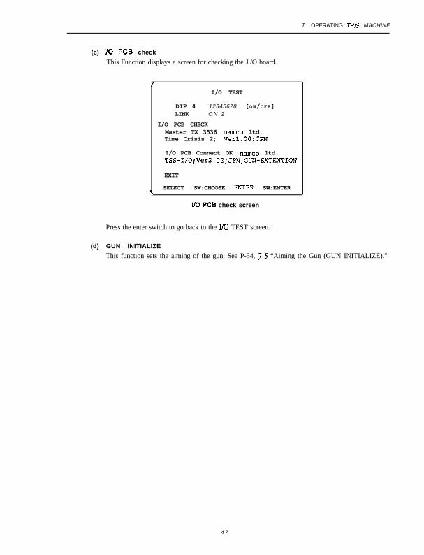
(c) l/O PCB check
This Function displays a screen for checking the J./O board.
/I/O TEST
DIP 4 12345678 [ON/OFF]LINK O N 2
I/O PCB CHECKMaster TX 3536 namco ltd.Time Crisis 2; Verl.OO;JPN
I/O PCB Connect OK namc~ ltd.TSS-I/O:Ver2.02;JPN,GUN-EXTENTION
EXIT
SELECT SW:CHOOSE ENTER SW:ENTERL
l/O PC8 check screen
Press the enter switch to go back to the UO TEST screen.
(d) GUN INITIALIZE
This function sets the aiming of the gun. See P-54, T-5 “Aiming the Gun (GUN INITIALIZE).”
4 7
7. OPERATING THLS MACHINE
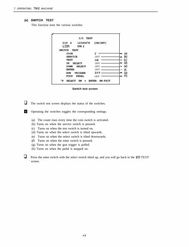
(e) SWITCH TEST
This function tests the various switches
I/O TEST
DIP 4 12345678 [ON/OFF]LIcyK ON 2
SWITCH TESTCOIN 0SERVICE OFFTEST ONUP SELECT OFFDOWN SELECT OFFENTER OFFGUN TRIGGER O F FFOOT PEDAL OFF
"P SELECT SW + ENTER SW:FXIT
- (4- (b)- (4- (d)1 If”,’- (9)- 0)
Switch test screen
q The switch test screen displays the status of the switches.
0 Operating the switches toggles the corresponding settings.
(a) The count rises every time the coin switch is activated.(b) Turns on when the service switch is pressed.(c) Turns on when the test switch is turned on.(d) Turns on when the select switch is tilted upwards.(e) Turns on when the select switch is tilted downwards.(f) Turns on when the enter switch is pressed.(g) Turns on when the gun trigger is pulled.(h) Turns on when the pedal is stepped on.
q Press the enter switch with the select switch tilted up, and you will go back to the I/O TEST’ screen.
4 8

7. OPERATING THIS MACHINE
(f) SOLENOID TEST
This function tests the blow-back mechanism of the gun.
I/O TEST
DIP 4 12345678 ION/OFF]LINK ON 2
SOLENOID TEST
PULL GUN TRIGGER TO ACTION
SELECT SW:CHOOSE ENTER SW:ENTER
Solenoid test screen
q Pull the gun trigger to activate the gun’s blow-back mechanism.
q Press the enter switch to go back to the I/O TEST screen.
4 9

7. OPERATING THIS MACHINE
7-4-5 MONITOR TEST
The MONITOR TEST performs various adjustments on the monitor.
q While on the MENU screen, select ‘MONITOR TEST and press the enter switch. The MONI-TOR TEST screen will then appear.
MONITOR TEST
GRADATION PATTERNCROSSRATCH PATTERN (CRT)CROSSEATCE PATTERN (PROJECTOR) --WHITE WI-W (H) [:IWHITE WI-W (M)WHITE WINDOW (L)INTERLACE PATTERN
if?:
VIEW ANGLE ADCJUST (CRT) (h)VIEW ANGLE ADJUST (PROJECTOR)FULL WHITEEXIT
(0(i)
SELECT SW:CHOOSE ENTER SW:ENTER
MONITOR TEST screen
q With the select switch, choose an option. The selected option will blink.
q Press the enter switch to display the corresponding pattern. To get out of the pattern screen,press the enter switch again.
(a) Displays a gradation pattern.(b) Displays a crosshatch pattern for CRT monitor. (This is not used for projectors.)(c) Displays a crosshatch pattern for projectors. (This not used for CRT monitors.)(d) Displays the white window (H, or high).(e) Displays the white window (M, or medium).(f) Displays the white window (L, or low).
, (g) Displays an interlace pattern.(h) Displays an adjustment screen for CRT monitors. (This is not used for projectors.)(i) Displays an adjustment screen for projectors. (This is not used for CRT monitors.)(j) Displays white all over the screen.
q Select EXIT and press the enter switch to go back to the MENU screen
5 0
7. OPERATING THHIS MACHINE
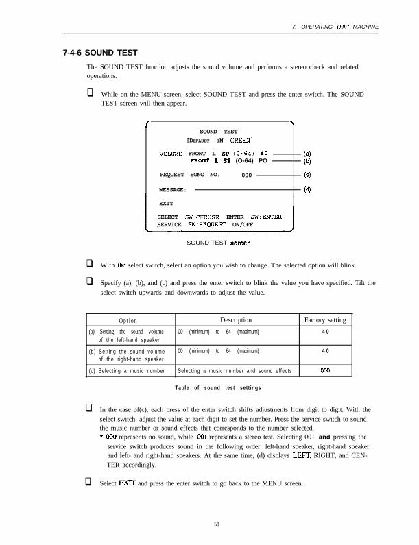
7-4-6 SOUND TEST
The SOUND TEST function adjusts the sound volume and performs a stereo check and relatedoperations.
q While on the MENU screen, select SOUND TEST and press the enter switch. The SOUNDTEST screen will then appear.
/ \SOUND TEST
[DEFAULT IN GREEN]
VOLrms FRONT L SP (O-64) 40PRONT R SF (O-64) PO
REQUEST SONG NO. 000
MESSAGE:
EXIT
SELECT SW:CHOOSE ENTER SW:EXTERSERVICE SW:REQUEST ON/OFF
(-3
(d)
SOUND TEST screen
q With the select switch, select an option you wish to change. The selected option will blink.
q Specify (a), (b), and (c) and press the enter switch to blink the value you have specified. Tilt theselect switch upwards and downwards to adjust the value.
O p t i o n Description Factory setting
(a) Setting the sound volume 00 (minimum) to 64 (maximum) 4 0
of the left-hand speaker
(b) Sett ing the sound volume 00 (minimum) to 64 (maximum) 4 0
of the right-hand speaker
(c) Selecting a music number Selecting a music number and sound effects 000
Table of sound test settings
q In the case of(c), each press of the enter switch shifts adjustments from digit to digit. With theselect switch, adjust the value at each digit to set the number. Press the service switch to soundthe music number or sound effects that corresponds to the number selected.* Ooo represents no sound, while 001 represents a stereo test. Selecting 001 and pressing the
service switch produces sound in the following order: left-hand speaker, right-hand speaker,and left- and right-hand speakers. At the same time, (d) displays LEFK RIGHT, and CEN-TER accordingly.
q Select EXlT and press the enter switch to go back to the MENU screen.
51

7. OPERATING THlS MACHINE
7-4-7 Displaying and initializing game data (ADS DATA)
This function displays various game data.
q While on the MENU screen, select ADS DATA and press the enter switch. The ADS DATA willthen appear.
q Power-off does not cause data to be lost, unless you execute ADS INITIALIZE or BACKUPMEMORY INITIALIZE in OTHERS.
B After the check, select EXIT and press the enter switch. You will then go back to the MENUscreen.
5 2

7. OPERATING THiS MACHINE
7-4-8 OTHERS
This function initializes backup memory and conducts related operations.
q While on the MENU screen, choose OTHERS and press the enter switch. The OTHERS screenwill then appear.
El
r \OTHERS
ROM1 Ver. 97/07/07 MON 21:15:59 -- (a)ROM2 Ver. 97/06/27 FRI 20:11:35
CLOCK --,--,-- --- --:- '-:-- --((b)
PCS TESTLANGUAGE JPN l"dlBACKUP NENORY INITIALIZE NO (e)
YESEXIT
SELECT SW:CHOOSE ENTER SW:ENTER
OTHERS screen
With the select switch, choose an option you wish to execute. The selected option will blink.(a) Displays the software version.(b) Not used in this machine.(c) Used to test the PC board (not used in running).(d) Selects a language used in the attract mode.
English : ENGGerman : GERFrench :FRASpanish : SPAPortuguese : PORItalian : ITA
(e) Initializes backup memory, Select YES and press the enter switch to clear all settings forGUN INITIALIZE, high score, and other parameters and to go back to the factory set-t i n g s .
35 The game will not proceed normally unless the software version (a) in the test mode of theright-hand side does not match that on the left-hand side. Contact your dealer.
q Press the enter switch to execute the blinking option.
m S e l e c t E X I T dan press the enter switch to go back to the MENU screen.
53
7. OPERATING THLS MACHINE
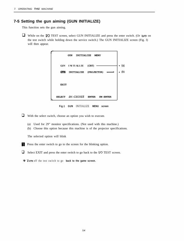
7-5 Setting the gun aiming (GUN INITIALIZE)
This function sets the gun aiming.
q While on the I/O TEST screen, select GUN INITIALIZE and press the enter switch. (Or turn onthe test switch while holding down the service switch.) The GUN INITIALIZE screen (Fig. I)will then appear.
GUN INITIALIZE MENU
GUN INITIALIZE (CRT)
c;IJN INITIALIZE (PROJECTOR) -
EXIT
SELECT SW:CHOOSE ENTER SW:ENTERL
Fig.1 GUN INITIALIZE MENU screen
q With the select switch, choose an option you wish to execute.
- (a)
- lb)
(a) Used for 29” monitor specifications. (Not used with this machine.)(b) Choose this option because this machine is of the projector specifications.
The selected option will blink
H Press the enter switch to go to the screen for the blinking option.
q Select EXIT and press the enter switch to go back to the I/O TEST screen.
+I+ Turn o f f t h e t e s t s w i t c h t o g o back to the game screen.
54

7. OPERATING T/i/S MACH/NE
GUN INITIALIZE (PROJECTOR)
This function sets the gun aiming (Fig. 2-I).,11
GUN INITIALIZE (PROJECTOR)
SHOOT AT SCREENTO CHECK GUN ACCtJFtACY
I PUSH ENTER SW:ADJUST GUN SIGHTUP SELECT SW + ENTER SW:EXIT
Fig. 2-l GUN INlTlALlZE (PROJECTOR) screen I
q The screen indicated in Fig. 2-1 allows you to check if the gun has the correct aim. Shoot the gunat the screen and the screen will display bullet impact where a bullet has reached. Check if thebullet impact is displayed at the point at which you aimed.
q While in the screen indicated in Fig. 2-1, press the enter switch (or step on the pedal) to go to thescreen illustrated in Fig. 2-2.
flPress the enter switch with the select switch tilted up to go back to the GUN NTL4L.IZE MENU.
+
AIM AT CENTER OF THE CROSSAND PULL GUN TRIGGER
\
Fig. 2-2 GUN INITIALIZE (PROJECTOR) screen 2
q You can set the gun aiming by shooting three points on the screen: the middle, top, and bottom.
q While in the screen illustrated in Fig. 2-2, aim at the center of the cross (+) displayed in themiddle of the screen and shoot the gun. After shooting it goes to the screen illustrated in Fig. 2-3.
5 5

Z OPERATING THlS MACHINE
AIM AT CENTER OF THE CROSSAN!3 PULL GUN TRIGGER
L
Fig. 2-3 GUN INITIALIZE (PROJECTOR) screen 3
H While in the screen illustrated in Fig. 2-3, shoot the gun at the center of the cross displayed at thetop of the screen. After shooting, it will go to the screen illustrated in Fig. 2-4.
+AIM AT CENTER OF THE CROSSAND PULL GUN TRIGGER
Fig. 2-4 GUN INITIALIZE (PROJECTOR) screen 4
q While in the screen illustrated in Fig. 2-4, shoot the gun at the center of the cross displayed at thebottom of the screen. The gun aiming is set. After shooting, it will go back to the screen illustratedin Fig. 2-l.
q While in the screen illustrated in Fig. 2-l. check that you can shoot properly at all points in allcomers of the frame. If the gun aim is not correctly initialized, press the enter switch (or step onthe pedal) to go to the screen illustrated in Fig. 2-2. Then adjust the gun again.
9K Turn off the test switch to go back to the game screen.
56

8. MAINTENANCE
8. MAINTENANCE
I 1 WARNINGQ
. Before performing maintenance (such as troubleshooting and repairs), always turn off the power switchto prevent service people and other persons around them from getting an electric shock, accident, orinjury.
. Some parts in the projector retain high heat and voltage after power-off. These may give you an electricshock or get you burned. Therefore take enough care not to touch any of them.
8-1 Maintenance and inspection
ml Do not forget to conduct periodic inspection
57

8. MAINTENANCE
8-l-l Greasing the plunger of the pedal Assy
-To be conducted by a technician only -
. Grease the plunger every six months.
q Loosen the four flange sockets (M6 x 20) on the cabinet body side.
q Remove the four flange sockets (M5 ⌧ 12) on the pedal Assy, then remove the connector. Thenremove the pedal Assy.
Pedal bracket
ge socket (M5 x 12)
ge socket (M6 x 20)
q Remove the four torque bolts (M5 x 12). then detach the cover.

8. MAINTENANCE
q Remove the two dished-end washer nuts (M4) and remove the microswitch.
H Remove the four dished-end washer nuts (M4) from the holder, then pull up the holder whilepulling the plunger.
fl Wipe off the grease from the pedal plate.
q Grease the plate and the spherical portion of the plunger.. Specified grease brand: Albania Grease No. 2 (Showa Shell)
Microswitch Holder
hed-end washer nut (M4)
q Assemble the pedal Assy in reverse order. (For adjusting the microswitch, see P-72, S-3-4 (1)“Replacing the Microswitch.“)
5 9
8-l-2 Checking the plunger of the pedal Assy for wear and tear
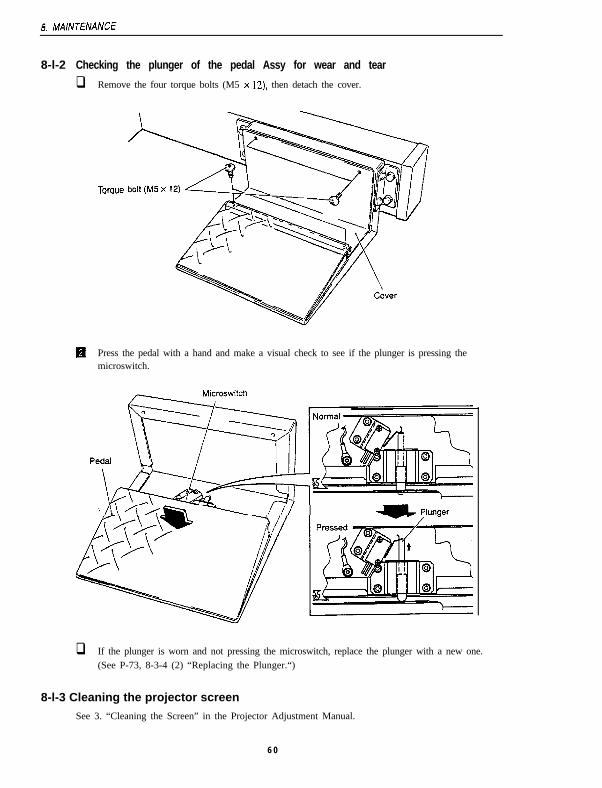
q Remove the four torque bolts (M5 x 12). then detach the cover.
Toraue
H Press the pedal with a hand and make a visual check to see if the plunger is pressing the-microswitch.
c Plunger
q If the plunger is worn and not pressing the microswitch, replace the plunger with a new one.(See P-73, 8-3-4 (2) “Replacing the Plunger.“)
8-l-3 Cleaning the projector screen
See 3. “Cleaning the Screen” in the Projector Adjustment Manual.
6 0

8. MAINTENANCE
8-2 Troubleshooting
j”““““‘““-,l Before carrymg out thus task, always turn off the power switch to prevent workers and people around
from getting an electric shock. accident, or injury and to protect the electric circuit from damage.
l In the case of trouble, first check that all connectors are firmly connected.
l If none of the cases described below applies to the troubie or ii any aciions do noiseem to solve the problem, contact your dealer.
. In repairing the game PC board, never conduct a continuity test with a tester or any-thing similar. This might destroy the ICs due to the inner voltage of the tester.
. To send any component for repairs, package it securely. When sending the game PCboard, in particular, wrap it with a sponge, air cap, or something similar and put it into acorrugated carton to avoid external forces.
8-2-l General
To be conducted by a technician only
The machine’sbehavior is not stable.It malfunctions.
This machine powers The circuit protector isoff when you do not activated and the powerexpect it. switch is off.
Cause
The supply voltage is notwithin the rated voltagerange.
Act ion
Disconnect the large-capacity electricequipment on the same line (such as anair-conditioner and large video machines)to secure a specified supply voltage.
See page
Turn the power switch back on. If thecircuit protector gets activated over andover again, this machine must bedefective. Contact your dealer.
Page 40
The soeakers do not 1 The sound volume is too low. 1 Re-adjust the sound volume. / Page51
The connector that links thesignboard Assy to theprojector (L) Assy is loose.
Connect the connector. Page 25
61

8. MAINTENANCE
8-2-2 Projector (L) and (R) Assys
-To be conducted by a technician only -
Symptom I CElUSeI Action See page
The projector doesnot pictures.
The connector that links theprojector to the projectorbase is loose.
Remove the front cover and connect theconnector.
Page 16
The connector to the rackAssy is loose.
Connect the connector. Page 66
cm ~~~
The projector is powered off. Power the projector on according to the -Projector Adjustment Manual.
The connector to the joint Detach the joint cover and connect theAssy is loose. connector.
Page 26
8-2-3 Signboard Assy
-To be conducted by a technician only -
I Symptom I Cause I Act ion See page
The connector is loose. Connect the connector. Page 25
The fluorescent lamp is dead. Replace the fluorescent lamp with a new Page 69one.
The glow lamp is dead. Replace the glow lamp with a new one. Page 69
8-2-4 Tower Assy
-To be conducted by a technician only -
Symptom Cause Act ion See page
ThegunAssy,doesnot work
The connector is loose.
The I/O PC board is defec-We.
Connect the connector firmly.
Replace the I/O PC board with a newOne.
Page 26
Page 70
8-2-5 Pedal Assy
-To be conducted by a technician only -
Symptom
The pedal does notWOk
Cause
The microswitch is out oforder.
Action
Replace the microswitch with a new one.
See page
Page 72
The connector is loose. Connect the connector. Page 27
The plunger is worn. Replace the plunger with a new one. Page 73
62

8. MAINTENANCE
8-2-6 Gun Assy
-To be conducted by a technician only -
Symptom CaU3.S ACli0l-l see page
The gun does notblow back.
The connector is loose.
;;;e;icroswitch is out of
Connect the connector. Page 74
Replace the microswitch with a new one. Page 78
The solenoid is worn. Replace the solenoid with a new one. Page 77
Bullet impact is poor. The lens is soiled. Clean the lens. Page 76
The gun initialize is out offocus.
Re-initialize the gun. Page 54
63

8. MAINTENANCE
8-3 Disassembling, reassembling and replacing the Assys and parts
8-3-l Projector (L) and (R) Assys
-To be conducted by a technician only -
(1) Detaching and reattaching the rear cover
r---” WARNING
l Before carrymg out this task always turn off the power swtch to prevent workers and people aroundthem from getting an electric shock, accident. or injury and to protect the electrfc circuit from damage.
q Remove the two Phillips truss screws (M$x 30). release the lock at the top middle, andopen the rear cover.
* The projector(R) is not locked.
Lock \Phillips truss screw (MS x 30)
q Reattach the components in reverse order.
64

8. MAINTENANCE
(2) Replacing the projector with a new one
A1 WARNING
0 Before carrying out this task, always turn off the power switch to prevent workers and people aroundthem from getting an electric shock, accident, or injury and to protect the electric circuit from damage.
0 The projector w e i g h s about 100kg. Detachment must be conducted by at least five people to preventaccidents.
a The signboard weighs about 30kg. For detachment, at least two people and a sufficient working spaceare needed to prevent accidents.
flDisassemble the pedal Assy, tower Assy, joint Assy, and signboard Assy. Detach theprojector (L) Assy from the projector (R) Assy. (See P-32,6-2-1 “Dividing” To be con-ducted by a technician only.“)
q Replace the projector with a new one. (See P-18.5-2-1 “Dividing Projector(L) and (R)Assys -To be conducted by a technician only.“)
q After replacing, reassemble the components in reverse order.
l After replacing the projector with a new one, always conduct the procedures on P-30.5-5 ‘Adjust ing the Projector.”
6 5

8 MAINTENANCE
(3) Detaching and reattaching the rack Assy
Q1 WARNING
0 Before carrying out this task, always turn off the power switch to prevent workers and people aroundthem from getting an electric shock, accident. or injury and to protect the electric circuit from damage.
0 Detach the rear cover. (See P-64,8-3-1 (1) “Detaching and Reattaching the Rear Cover.“)
q Disconnect the five connectors at the locations illustrated below.
q Loosen the two Phillips hexagon bolts (with flat and spring washers) (M6 x 16). pull therack Assy a little towards yourself, then lift it up to detach.
Phillips hexagon bolt (with flatand spring washers) (M6 x 16)
q Reattach the rack Assy in reverse order.
q After replacing, always check how this machine works and check the settings. (See P-43,7-4 ‘Test Mode” and P-54.7-5 “Setting the Gun aiming (GUN INITIALIZE).“)
66

8. MAINTENANCE
(4) Replacing the game PC board with a new one
. Before carrying out this task, always turn off the power switch to prevent workers and People around
them from getting an electric shock, accident. or injury and to protect the electric circuit from damage.
0 Detach the rear cover. (See P-64. 8-3-l (1) “Detaching and Reattaching the Rear Cover.“)
a D’lsconnect the six connectors.
q Remove the four Phillips round head screws (with flat and spring washers) (Mb X 10) addetach the F panel (I).
Phillips round haadnd sprin!a0)’ - Disconnect the
I connectors.
Disco&cl theconnectors.
‘\
k panel (1)
6 7

8. MAINTENANCE
q Remove the four Phillips round head screws (with flat and spring washers) (M3 x 6) fromthe top board and the four studs and the two Phillips round head screws (with flat andspring washers) (M3 x 6) from the bottom board. Then detach the two game PC boards.
Phillips round head screw(with flat and spring washers) (M3 x 6)
Stud .MAIN (I) game PCboard (bottom board)
Phillips round head screw(with flat and springwashers) (M3 x 6)
’ <
H Attach new game PC boards in reverse order.
Ii]l Reassemble them in reverse order.
q After replacing, always check that this machine works and check the settings. (See P-43,7-4 ‘Test Mode” and P-54.7-5 “Setting the Gun Aiming (GUN INITIALIZE).“)
0 Before sending game PC boards, wrap them with a sponge, air cap, or somethingsimilar, and put them into a corrugated carton or something similar to avoid externalforces.
6 8

8. MAINTENANCE
8-3-2 Signboard Assy
-To be conducted by a technician only -
(1) Replacing the fluorescent lamp and glow lamp with new ones
,- 1 W A R N I N G ,Q
0 Before carrying out this task. turn off the power switch to prevent workers and people around them fromgetting an electric shock, accident, or injury and to protect the electric circuit from damage.
m Remove the four torque bolts (M5 x 12) and detach the stay while holding the signboard
panel to detach.
q Pull up the signboard panel.
q Replace the fluorescent lamp (4OW) or glow lamp.
-. . Torque bolt (M5 x 12) stavPluorescenr lamp ---,
q Reassemble in reverse order.
6 9

8. MAINTENANCE
8-3-3 Tower Assy
-To be conducted by a technician only -
(1) Replacing the l/O PC board with a new one
. Before carrying out this task, always turn off the power switch to protect the electriccircuit from damage.
. When disconnecting the connectors from the l/O PC board, always hold the UO PCboard.
. When connecting the connectotx to the I/O PC board, insert the white connector to thetop and the red one to the bottom I/O PC board.
0 Remove the six torque bolts (M5 x 12) and detach the back cover.
, I/O PC board
Tower Assy (rear)

8. MAINTENANCE
q Disconnect the four connectors of the I/O PC board.
11 Remove the four cup screws (M) (M3 x 6), then detach the I/O PC board.
Connec to r s
q Attach a new board in reverse order.
71

8. MAINTENANCE
0-3-4 Pedal Assy
-To be conducted by a technician only -
(1) Replacing the microswitch with a new one
0 Before carving out this task. always turn off the power switch to protect the electriccircuit from damage.
q Remove the four torque bolts (M5 x 12). then detach the cover
Torque bolt(M5x 12)
q Remove the two Phillips round head screws (with flat and spring washers) (M3 x 16) andtwo fasten terminals. then detach the microswitch.
Phill ips round head screw (with flatwashers) (M3 x 16)
oswitch
n Rple ace the microswitch with a new one.
q After replacing, press the pedal to check if the new microswitch works well.
q If the microswitch does not work well, adjust it by loosening the two dished-headnuts (M4).’
washer
vWhen pressed
72

8. MAINTENANCE
(2) Replacing the plunger with a new one
0 Before carrying out this task, always turn ofl the power switch to protect the electriccircuit from damage.
q Detach the holder. (See P-58,8-1 -1 “Greasing the Plunger of the Pedal Assy.“)q Pull the plunger out of the holder, then replace it with a new one. At that time, grease the
new plunger all over.. Specified grease brand: Albania Grease No. 2 (Showa Shell)
Holder
H Wipe off the old grease from the plate of the pedal, then apply a new supply of grease toit.
here
q Reassemble in reverse order. (For adjusting the microswitch, see P-72.8-3-4 (1) “‘Replac-ing the Microswitch with a New One.“)
7 3

8. MAINTENANCE
8-3-5 Gun Assy
-To be conducted by a technician only -
(1) Replacing the gun Assy with a new one
0 Before carrying out this task, always turn off the power switch to protect the electric
circuit from damage.
0 Remove the six torque bolts (M.5 x 12) and detach the holder cover.
q Disconnect the two connectors.q Remove the two dished-end washer nuts (M6) from the back of the holder cover and
detach the gun Assy.
//
Back of the holder cover ~ /
Dished-end washer. //I I
q Attach the new gun Assy in reverse order.
74

8. MAINTENANCE
(2) How to open the gun slide
. Before carrying out this task, always turn off the power switch to protect the electriccircuit from damage.
q Remove the four cap bolts (M3 x IO). one button bolt (M4 x 25). and one hexagon boxnut (M4), then detach the gun slides (L) and (R).
q Attach the gun slide in reverse order.
Gun slide (L) Button bolt (M4 x 70) Gun slide (R)
Cap boil (M3 x 10) Hexagon box nut (M4) \ Cap bolt (M3 x 10)
7 5

8. MAINTENANCE
(3) How to open the gun cover
. Before carrymg out this task, always turn off the power switch to protect the electriccircui t f rom damage.
q Remove the gun slides (L) and (R). (See P-75.8-3-5 (2) “How to Open the Gun Slide.“)
q Place the gun cover(L) face-down, and remove the four button bolts (M4 x 10). onebutton bolt (M4 x 25), four hexagon box nuts (M4). and one cap bolt (M3 x 10) fixing thegun cover(R). Then detach the gun cover(R). At that time, take care not to let the lensfall.
Button bolt Gun cover (R)(M4 x 25)
/ Cap boil (M3 x 10)
Button bolt (M4 x
fl Reassemble in reverse order. At that time. pay attention to the direction of the lens. (Makethe spherical face of the lens face toward the muzzle.)
Watch the direction of thelens. (Make the spherfcafsurface face the muzzle.)
7 6

8. MAINTENANCE
(4) Replacing the solenoid with a new one
. Before carrying out this task, always turn off Ihe power switch to protect the electriccircui t f rom damage.
0 Detach the gun cover and gun slide.(See P-75,8-3-S (2) “How to Open the Gun Slide” and P-76, S-3-5 (3) “How to Open theGun Cover.“)
q Disconnect the connectors of the solenoid.
q Remove the cap bolt (M3 x 10) on the gun cover(L) and detach the solenoid bracket.
q Remove the cup screw (M) (M3 x 8) and detach the ground wire.
q Loosen the nuts (16mm in nominal diameter) fixing the solenoid.
q Poll out the solenoid.
q Remove the two cup screws (M) (M4 x 6) and detach the slide guide.
q Pull out the solenoid plunger. At that time, take care not to lose the spring.
------------- ------- _1
Cap boil (M3 x 10)
Cup screw (M) (M3 x 8) Toothedwasher
Slide guide
q Attach the components in reverse order. At that time, match the D-type hole of the sole-noid bracket to the D shape of the solenoid. Also pay attention to the order to attach theE-type snap rings and spacers.
Smcen Slide guide
Harness outlet ( i t mudf ace downwards )
P&ger ’E-type snap r ings
7 7

8. MAINTENANCE
(6) Replacing the microswitch with a new one
. Before carrying out this task, always turn off the power switch to protect the electriccircui t f rom damage.
Detach the gun cover (R) and gun slide (R). (See P-75,8-3-5 (2) “How to Open the GunSlide” and P-76,8-3-5 (3) “How to Open the Gun Cover.“)
Replace the microswitch with a new one.
Attach the new microswitch in reverse order.
(6) Replacing the tube with a new one
0 Before canying out this task, always turn off the power switch to protect the electriccircui t f rom damage.
q Remove the gun Assy. (See P-74, S-3-5 (1) “Replacing the Gun Assy.“)
q Remove the two button bolts (M4 x IO), then detach the connector cover.
q Remove the gun slides (L) and (R) and gun cover(R). (See P-76,8-3-5 (3) “How to Openthe Gun Cover.“)
q Detach the solenoid bracket and detach the solenoid connectors and ground wire. (See P-77,8-3-5 (4) “How to Replace the Solenoid with a New One.“)
q Disconnect the connectors of the sensor and the fasten terminals of the microswitch.
H Remove the button bolt (M4 x 10) fixing the tube to the gun cover(L) to detach the tube.
‘a Attach the new tube in reverse order.
Fasten terminal(microswitch)
Connector (solenoid)
II /
Button bolt (M4 x 10)
Connector cover
Gun cover (R)
70

9. LNSCARD
DISCARD
,--A WARNING
l Before discarding this machine, collect. transport, and dispose of its components according to relevantlaws.
. If you wish to entrust a third party to collect, transport, and dispose of this machine to discard, employagents specializing in the respective works.
. In discarding this machine, do not detach the screen from the projector. The removed screen or theinternal lens may cause a fire or get your sight lost or burned.
79

10. PARTS L/ST
10. PARTS LIST
1 O-l Front Assy
0 0\ \
8 0

No. Part Q ’ t y Model and rat ing Part I
1 Joint bracket 1 643-051
2 Washer C 4 450-017
3zation Manual (this manual) Ill 1 680-005
4 Spacer 2 643153

10. PARTS LIST
1 O-2 Projector (1) Assy
.
. t
Ll.ci I . .
10. PARTS LISJ
NO. Part I Q’tv I Model and ratina I Part#
1 1 Joint stay L I 1 I I 680-l 14
2 1 Projector I 1 / SD-V5070N2
3 Front cover 1 680-112
4 1 Front sticker (DX) L I 1 I 680-117
5 1 Warning sticker (high voltage) I 1 I 1 461-371
6 / Caster I 4 I 420SN75 102-013
7 1 Adiushent bolt 1 4 1 M16x7.5 1 102.166
8 Ediustor bracket
9 ( Woofer cover I 1 I 671-115
1 0 Woofer speaker 1 SWM1034-A/E 006-115
11 I Pipe duct 1 1 1 LQ242 (L 1SOmm) I 006-116
12 Side plate sticker (DX) L 1 680-116
13 Signboard hook (DX) 1 680-115
14 Ventilation panel B 1 450-018
15 Projector base L 1 680-111
16 Small lid 1 619-214
17 Rear cover (DX) 1 680-113
18 Caution sticker (maintenance) 1 461.359
19 Suckle (mill) 1lol-ol”r
20 Coin lock t C-08-1 (random number)
21 Key washer 1 450-124
22 1 Pmiector Adiustment Manual 1 1 / F o r PTV-P -
.‘I If you need No. 20 parts of a specified number (the same number), consult your dealer.

10. PART5 LIST
1 O-3 Projector (R) Assy
-
i
i-

10. PARJS LIST
NO. Part Q’ty Model and rating Part #
1 Joint stay R 1 680-l 64
2 Cover plate 1 680-212
3 Projector 1 SD-V5070N2 -
4 Front co”er 1 660-112
5 Front sticker (OX) R 1 660-l 67
6 Warning st icker (high voltage) 1 461-371
7 caster 4 420SN75 102-013
a Adjustment bol¶ 4 M16x75 102-l 66

10. PARTS LIST
10-4 Signboard Assy
@\
0
0
<
.
-
.
.
.
.

10. PARTS LIST
NO. Pali wty Yodel and rating Part #
1 Connector cover (DX) 1 MO-41 4
2 Side cover (DX) L 1 MO-412
3 1 Sox(DX) I 1 I 680-411
4 Stay 2 671-214
5 1 Side cover(DX) R 1 1 680-462
6 Speaker cover (DX) 1 680-413
7 Signboard panel 1 671-212
8 Fluorescent lame 1 F L - 4 0 W -
9---Fluorescent lamp fixture I i I M4111A I -
10 Speaker mask 4 671-217
11 1 Soeaker I 4 I EASlOP542A 006-108
87

10. PARTS LIST
1 O-5 Joint Assy

10. PARTS LlSJ
No. Part my Model and rat ing Part #
1 J o i n t cover (DX) 1 680-612
2 Joint (DX) 1 660-611
89

10. PARTS L/ST
1 O-6 Control base Assy

10. PARTS L/S7
N O . PWI I Q’tY I Model and rating I ~Part #
1 I Control base I 1 I 671-311
2 Switching regulator 1 VS75E24 (24V 75W) 009-117
3 Switching regulator 1 VSloOB-12(12V 1OOW) 009-116
91

70. PARTS L/ST
1 O-7 Rack Assy
?
I -e *I
92

10. PARTS LIST
No. ( Part I Q’ty I Model and rating I Part x
1 Bracket (L) 1 46 l-050
2 1 Bracket CR) I 1 I 1 461-051
3 I cover I 1 I 1 4 6 1 - 7 1 6
4 1 Case I 1 I 461.718
5 F panel (1) 1 461-719
6 I Fan motor 1 1 / 4715MS-lOT-SW-BOO I 005-209
7 1 Finger g u a r d
6 Switching regulator 1 V575B-5 (5V 75W) 00%111
9 Switching regulator 1 VS3OB.3 (3V 3OW) 009- 100
10 Stud 4 461-717
93

10. PARTS L/ST
10-B Cord box Assy
0\
94

10. PARTS LIST
No. ~~ Part I Q’w I Model and rating Part X
1 1 Noise filter 1 1 1 SUP-C4210-F I -2 Cord box 1 660-311
3 Power switch 1 CP-S2PAl-MlOAorCP32EWlO -
95

10. PARTS L/ST
IO-9 Tower Assy
- -
96
10. PARTS LIST
No. 1 Part I Q’W I Model and rating Part #
1 Coin cover 1 671-622
2 Beam (8) DX 1 680-513
3 I Main tower 1 / 671-611
< I8actcuver / 1 / j 6 7 1 - 6 1 6
5 caster 2 420R-N 36 102-054
6 I 8onomcover 1 1 671617
7 Pipe cower 2 671-619
8 Pedal bracket 4 631-115
9 Undernice DX 1 680-511
11 Gun base (R) 1 671.662
12 Holder co”er (R) 1 671673
13 1 Seam(AlOX I 1 680-512
14 Pop sticker 1. Set of pop and description stickers 671660
15 Description sticker 1
16 Holder cover (L) 1 671623
17 G u n base (L) 1 671612
16 G u n Assy (R) 1 296-902 21
19 G u n holder 2 671-616
20 Gun plate 2 2 671.511
21 I/O PC board 2 -
22 Adjustor bait 3 M16x75 102-166
23 Gun Assy (8) 1 296-903
v For No. 10, see P-102, lo-12 “Coin Assy.”
‘2) For Nos. 18 and 23, see P-100.10-11 “Gun Assy,”
97

IO. PARTS LIST
1 O-l 0 Pedal Assy

70. PARTS L/ST
When % is of the hexagon socket head button bolt type. [Hexagon socket head button bolt:
N o . Parl Q’V Model and raring
1 Pedal plate 1
Part #
1 631-215
2 I Pedal I 1 I I 631-212
3 Pedal base-
1 ~~~ 1 I I !?YL
4 SPW (4 1 631-221
5 Spring cover 1 I 631-218
6 1 Rubber plug cushion 1 2 1 TM-96, article #3 106-017
7 Rubber stopper 1 631-217
8 I Plunger I 1 I 1 631-219
9 ) Holder I 1 I j 631-213
1 0 Spring (W 1 631-222
1 1 Switch stay 1 I 631-220
12 I Microswitch / 1 1 K3L13 1 OOQ-027
1 3 Epto sealer 1 Sealant EE-910 WlO x t15 x L246 106-041
1 4 I Cover I 1 I 1 631-214
15 I Plate I 1 I 1 631-216
When I is of the f lush screw type.
NO. Part w Model and rating Part #
1 floor plate 1 631-255
2 Pivot 1 631-252
3 1 Main body I 1 I / 631-251
4 SWg (4 1 631-221
5 I Sotina cover I 1 I / 631-218
9 9

IO. PARTS LIST
1 O-11 Gun Assy
100
10. PARTS LISJ
Gun Assy (R) (red)
NO. Pall O’ty Model and rat ing P a r t #
1 Gun cover (L-R) 1 296-461
2 Trigger spring 1 / 296-421
Rubber sound absorber
Gun Assy (B) (blue)
No.
1 Gun cover (L-B)
3 Trigger(B)
9 Gun cover (R-8)
1 0 Gun slide (R-B)
1 5 Gun slide (L-B)
Gun Assy (B)
Part Q’W
1
1
1
1
1
1
Model and rat ing PaH #
296-491
296-495
296-492
296-494
296-493
296-903
1 0 1

10. PARTS LIST
1 O-l 2 Coin Assy
102

10. PARTS L/ST
No. I Pan I Q’tY I Model and rating Part #
1 Front plate Assy 2 With coin selecfor HO0 100-143
2 1 Coin slot sticker (6) I 2 I lPLAYY200 I 100-102
3 / Cain slot sticker (C) I 2 ICONTINUE Yl Ml ~~ ~~ ~ I 1oo-1034 Coin lock 1 C-66-l (random number) 101-011 .”
5 Front cover 1 461-036
6 Service door (C) 1 461-713
7 1 Coin door 461-038
8 Electronics lock 1 VM78Z. 101-034
9 I Counter / 2 1 NX-06F054 I 003-033
10 ( Coin case I 1 I ( 464-022
1 1 suckle (C) 1 100-121
12 1 Cash box IK) I 1 I 1 461-040
1 3 1 Coin slot sticker (A) I 2 I lPL4YYlOO 100-101
1 4 Service plate (B-2P) 1 461-724
1 5 1 Testswi tch 1 2 1 SDS-103A-03#13SJ 1 000-312
16 1 Service switch I 2 I SDAP-l-1R (red) I 000-334
1 7 / Service sticker M (8) I 2 I 461-722
16 1 Selectswitch 1 2 1 SDSA-331G-CR I 000-337
1 9 Enter switch 2 SDAP-l-l G (green)
Coin selector 2 AD-61 P Yl 00
“1 If you need No. 4 parts of a specified number (the same number), consult your dealer.
000-335
100-015
103

10. PARTS L/ST
104

r-------
I
.i.-.-.-c
- I - -
! /! i/ ji !i !I !i !I 1
I!I

F2
.$
-.-.-.