ret systems
DESCRIPTION
DatasheetsTRANSCRIPT

KATHREIN’sRemote Electrical Tilt SystemOverview of related products, installation and control possibilities
Edition 2012
99811878_Remote.indd 199811878_Remote.indd 1 16.05.2012 11:25:3216.05.2012 11:25:32

Kathrein’s Remote Electrical Tilt General Information
2
The answer to all current and future network demands
Network planning is becoming ever more complicated,especially with 3G (UMTS) and 4G (LTE).The challenge for wireless network operators is to balance coverage, capacity, call quality and costs in order to gain maximum revenue from their network. Each of the above factors affects the others and so network engineers use many different techniques to establish the right balance they are trying to achieve.
One of these methods is adjusting the antenna’s downtilt. Here, the engineer must take into consideration certain facts, such as the weather, access to the cell site, availability of specialized installation teams and special equipment etc. Moreover, such an antenna adjustment can typically take several hours to perform.Since the cell site is usually switched off for safety reasons during such an adjustment, this results in lost calls and therefore revenue whilst these changes are being made. Consequently, operators tend to make fewer adjustments and so networks are often left operating unoptimized, which also eventually results in lost revenue for the operators.
However, with Kathrein’s Remote Electrical Tilt (RET) unit engineers can make the necessary adjustments without shutting down the whole system!
Further advantages of using Kathrein’s
RET system:
No need for specialized teams trained in altitude work or with special safety skills
Limited site access and/or time restrictions are not so important
No special platforms or other means of access to the antenna are required
Adjustments can be made and the relevant measurements performed speedily
Network alterations can be carried out irrespective of weather conditions
No reduction in coverage – cells remain fully operational whilst changes are being made
Operators estimate that approx. 20 % of UMTS equipment can be saved by using such a RET system
99811878_Remote.indd 299811878_Remote.indd 2 16.05.2012 11:25:5116.05.2012 11:25:51
Kathrein’s Remote Electrical Tilt General Information
3
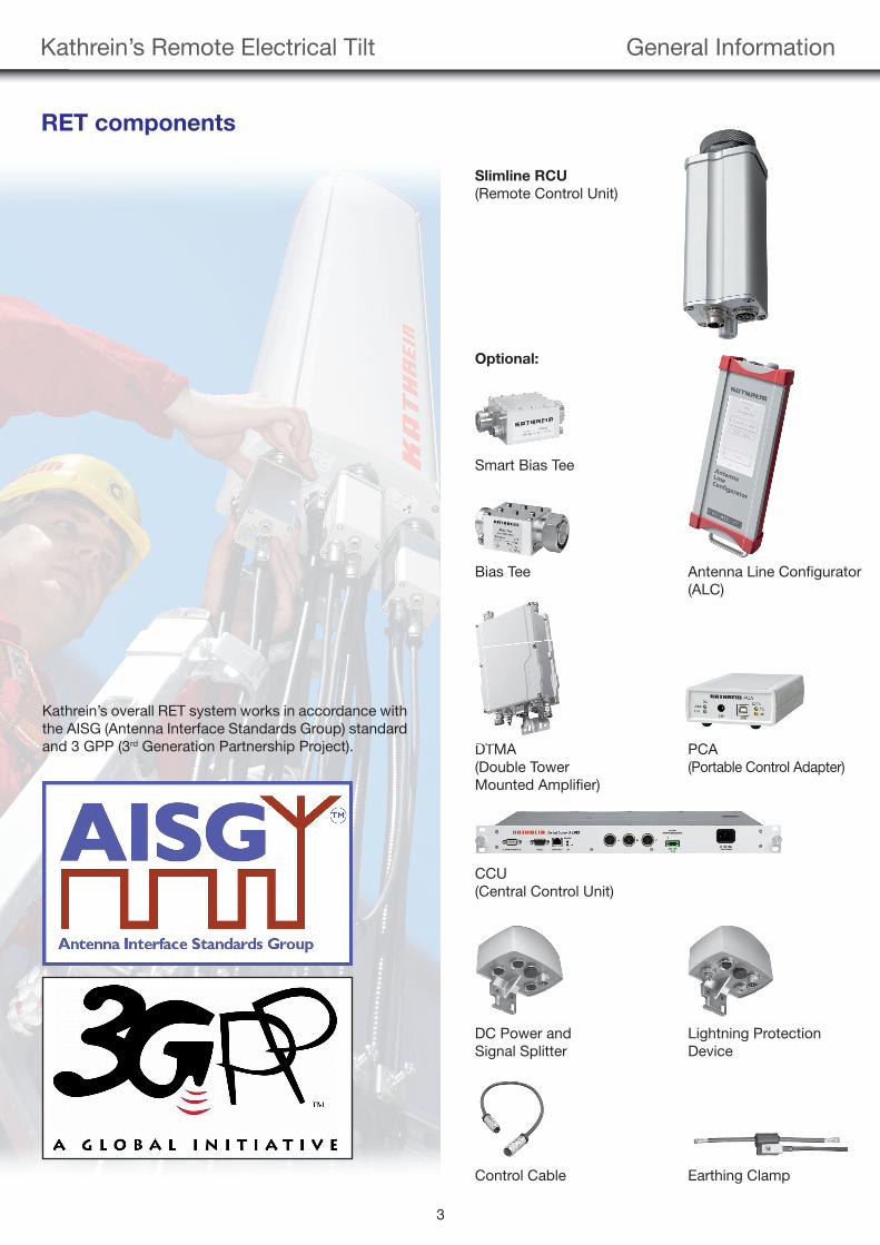
RET components
Kathrein’s overall RET system works in accordance with the AISG (Antenna Interface Standards Group) standard and 3 GPP (3rd Generation Partnership Project).
Slimline RCU
(Remote Control Unit)
Optional:
Smart Bias Tee
Bias Tee Antenna Line Confi gurator (ALC)
DTMA PCA(Double Tower (Portable Control Adapter)Mounted Amplifi er)
CCU (Central Control Unit)
DC Power and Lightning Protection Signal Splitter Device
Control Cable Earthing Clamp
DT
99811878_Remote.indd 399811878_Remote.indd 3 16.05.2012 11:25:5516.05.2012 11:25:55
Kathrein’s Remote Electrical Tilt General Information
4
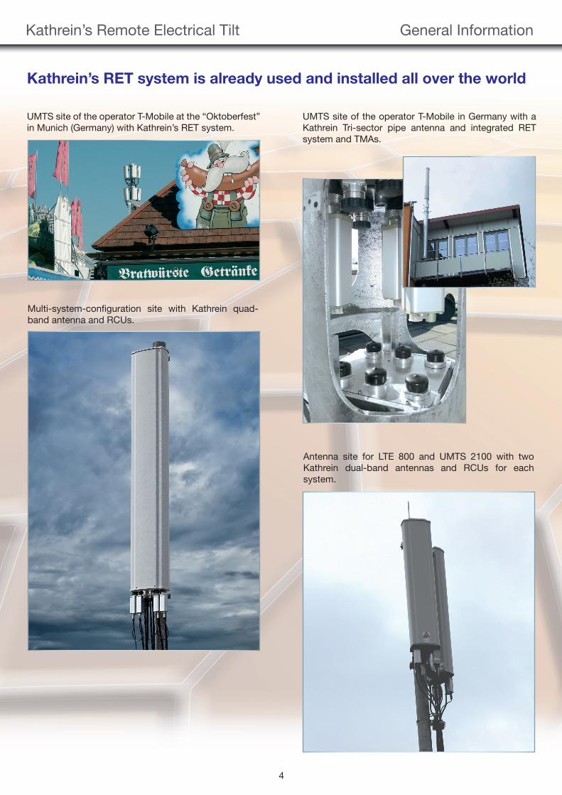
Kathrein’s RET system is already used and installed all over the world
UMTS site of the operator T-Mobile at the “Oktoberfest” in Munich (Germany) with Kathrein’s RET system.
UMTS site of the operator T-Mobile in Germany with aKathrein Tri-sector pipe antenna and integrated RET system and TMAs.
Multi-system-confi guration site with Kathrein quad-band antenna and RCUs.
Antenna site for LTE 800 and UMTS 2100 with two Kathrein dual-band antennas and RCUs for each system.
99811878_Remote.indd 499811878_Remote.indd 4 16.05.2012 11:26:0216.05.2012 11:26:02

Kathrein’s Remote Electrical Tilt Control Devices
5
Devices for controlling the RET System
Antenna Line Configurator
The antenna line configurator is a stand-alone device for the configuration and control of AISG antenna line products such as Kathrein’s RET system. For the opera-tion, no external power supply and no PC or laptop are required. The Antenna Line Configurator is made for on-site use and has a touch-screen display which is sunlight visible. Its size is only 265 x 102 x 37 mm and it has an extra clip to securely fix it during the site access.
A variety of functions can be controlled with the Antenna Line Configurator, where the most important ones are:
Scan for AISG devices
Select and confi gure the scanned devices (e.g. adjust the down-tilt of the RCU)
Documentation and protocolling of antenna installation parameters in a report fi le
Update the software of the used antenna line devices such as RCUs, DTMAs etc.
Check the mechanical downtilt of the antenna with the internal tilt sensor
All complex functions and data which need more stor-age can be transferred via WiFi to an arbitrary mobile device such as a PDA, smartphone or laptop. A USB connection between the Antenna Line Configurator and a laptop is also possible. The mobile device does not need special software, a standard web-browser is sufficient.With one single Antenna Line Configurator, up to nine RCUs can be controlled, depending on the system con-figuration and the length of the control cable.
99811878_Remote.indd 599811878_Remote.indd 5 16.05.2012 11:26:1116.05.2012 11:26:11
Kathrein’s Remote Electrical Tilt Control Devices
6
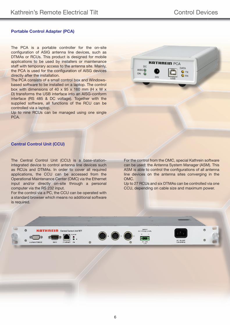
Central Control Unit (CCU)
The Central Control Unit (CCU) is a base-station-integrated device to control antenna line devices such as RCUs and DTMAs. In order to cover all required applications, the CCU can be accessed from the Operational Maintenance Center (OMC) via the Ethernet input and/or directly on-site through a personal computer via the RS 232 input. For the control via a PC, the CCU can be operated with a standard browser which means no additional software is required.
For the control from the OMC, special Kathrein software can be used: the Antenna System Manager (ASM). This ASM is able to control the confi gurations of all antenna line devices on the antenna sites converging in the OMC.Up to 27 RCUs and six DTMAs can be controlled via one CCU, depending on cable size and maximum power.
Portable Control Adapter (PCA)
The PCA is a portable controller for the on-site confi guration of ASIG antenna line devices, such as DTMAs or RCUs. This product is designed for mobile applications to be used by installers or maintenance staff with temporary access to the antenna site. Mainly, the PCA is used for the confi guration of AISG devices directly after the installation.The PCA consists of a small control box and Windows-based software to be installed on a laptop. The control box with dimensions of 40 x 95 x 160 mm (H x W x D) transforms the USB interface into an AISG-conform interface (RS 485 & DC voltage). Together with the supplied software, all functions of the RCU can be controlled via a laptop.Up to nine RCUs can be managed using one single PCA.
99811878_Remote.indd 699811878_Remote.indd 6 16.05.2012 11:26:1816.05.2012 11:26:18
Kathrein’s Remote Electrical Tilt Control Devices
7
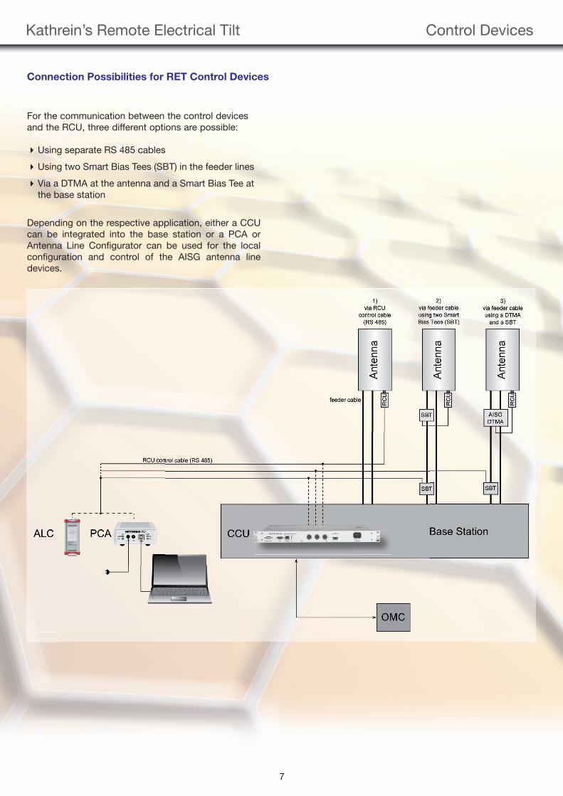
Connection Possibilities for RET Control Devices
For the communication between the control devices and the RCU, three different options are possible:
Using separate RS 485 cables
Using two Smart Bias Tees (SBT) in the feeder lines
Via a DTMA at the antenna and a Smart Bias Tee at the base station
Depending on the respective application, either a CCU can be integrated into the base station or a PCA or Antenna Line Configurator can be used for the local configuration and control of the AISG antenna line devices.
99811878_Remote.indd 799811878_Remote.indd 7 16.05.2012 11:26:2516.05.2012 11:26:25
Kathrein’s Remote Electrical Tilt Control Possibilities
8
Ways of controlling the RET System:
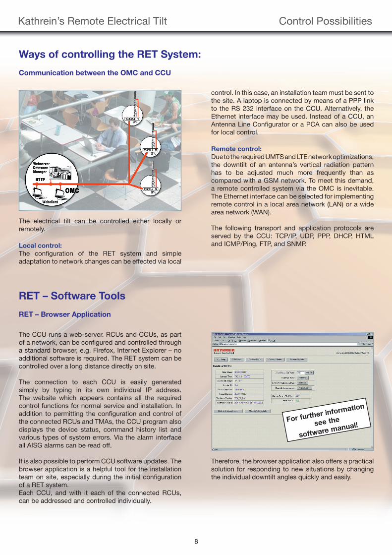
Communication between the OMC and CCU
The electrical tilt can be controlled either locally or remotely.
Local control:
The confi guration of the RET system and simple adaptation to network changes can be effected via local
RET – Software Tools
RET – Browser Application
The CCU runs a web-server. RCUs and CCUs, as part of a network, can be confi gured and controlled through a standard browser, e.g. Firefox, Internet Explorer – no additional software is required. The RET system can be controlled over a long distance directly on site.
The connection to each CCU is easily generated simply by typing in its own individual IP address. The website which appears contains all the required control functions for normal service and installation. In addition to permitting the confi guration and control of the connected RCUs and TMAs, the CCU program also displays the device status, command history list and various types of system errors. Via the alarm interface all AISG alarms can be read off.
It is also possible to perform CCU software updates. The browser application is a helpful tool for the installation team on site, especially during the initial confi guration of a RET system. Each CCU, and with it each of the connected RCUs, can be addressed and controlled individually.
Therefore, the browser application also offers a practical solution for responding to new situations by changing the individual downtilt angles quickly and easily.
control. In this case, an installation team must be sent to the site. A laptop is connected by means of a PPP link to the RS 232 interface on the CCU. Alternatively, the Ethernet interface may be used. Instead of a CCU, an Antenna Line Confi gurator or a PCA can also be used for local control.
Remote control:
Due to the required UMTS and LTE network optimizations, the downtilt of an antenna’s vertical radiation pattern has to be adjusted much more frequently than as compared with a GSM network. To meet this demand, a remote controlled system via the OMC is inevitable. The Ethernet interface can be selected for implementing remote control in a local area network (LAN) or a wide area network (WAN).
The following transport and application protocols are served by the CCU: TCP/IP, UDP, PPP, DHCP, HTML and ICMP/Ping, FTP, and SNMP.
For further information
see the
software manual!
99811878_Remote.indd 899811878_Remote.indd 8 16.05.2012 11:26:3216.05.2012 11:26:32
9
Kathrein’s Remote Electrical Tilt Software Tools
RET – Antenna System Manager (ASM)
Via the Operational Maintenance Center (OMC), hun-dreds of sites are controlled at the same time. With the CCU browser application, not more than one CCU can be controlled at once. Hence, this tool is not suit-able for an extensive site control. Therefore, Kathrein has developed the Antenna System Manager (ASM), a special software tool which gathers the access to the functionality of all CCUs into one single application. The ASM is a SNMP based software installed on the OMC computer for detecting faults and realizing network changes and events in real-time. It offers an optimized solution for controlling up to 10,000 CCUs at once. The ASM is based on a Client Server Architecture whose database contains all important network parameters needed for the configuration and the current status of all connected antenna line devices. This tool provides an excellent possibility to manage a whole network via one single program integrated in the OMC .
For more detailed information, please contact your local Kathrein partner or [email protected]
99811878_Remote.indd 999811878_Remote.indd 9 16.05.2012 11:26:3516.05.2012 11:26:35
Kathrein’s Remote Electrical Tilt Instructions
10
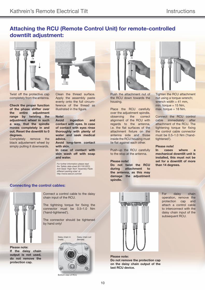
Attaching the RCU (Remote Control Unit) for remote-controlled
downtilt adjustment:
Twist off the protective cap completely from the antenna.
Check the proper function
of the phase shifter over
the entire adjustment
range by twisting the
adjustment wheel in such
a way, that the spindle
moves completely in and
out. Reset the downtilt to 0
degrees.
Completely remove the black adjustement wheel by simply pulling it downwards.
Clean the thread surface. Apply the assembly pasteevenly onto the full circum-ference of the thread as illustrated in the fi gure.
Note!
Avoid ingestion and
contact with eyes. In case
of contact with eyes rinse
thoroughly with plenty of
water and seek medical
advice.
Avoid long-term contact
with skin.
In case of contact with
skin wash off with soap
and water.
Push the attachment nut of the RCU down towards the housing.
Place the RCU carefully over the adjustment spindle, observing the correct alignment of the RCU with regards to the antenna, i.e. the fl at surfaces of the attachment fi xture on the antenna side and those inside the RCU housing must lie fl at against each other.
Push-up the RCU carefully to the stop at the antenna.
Please note!
Do not twist the RCU
during attachment to
the antenna, as this may
damage the adjustment
spindle.
Tighten the RCU attachment nut using a torque-wrench;wrench width = 41 mm,min. torque = 15 Nm,max. torque = 18 Nm.
Connect the RCU control cable immediately after attachment of the RCU. The tightening torque for fi xing the control cable connector must be 0.5–1.0 Nm (‘hand-tightened’).
Please note!
In cases where a
mechanical downtilt unit is
installed, this must not be
set for a downtilt of more
than 14 degrees.
Connecting the control cables:
Connect a control cable to the daisy chain input of the RCU.
The tightning torque for fi xing the connector must be 0.5–1.0 Nm (‘hand-tightened’).
The connector should be tightened by hand only!
For daisy chain operation, remove the protection cap and attach a control cable to interconnect with the daisy chain input of the subsequent RCU.
Daisy chain in (male)
Daisy chain out(female)
Bottom view of RCU
Please note:
If the daisy chain
output is not used,
do not remove the
protection cap.
Please note:
Do not remove the protection cap
on the daisy chain output of the
last RCU device.
For further information please read the ‘Safety data-sheet (91/155 EEC), Anti-Seize ‘High-Tech’ Assembly Paste different packing sizes’ at http://www.weicon.com/en
99811878_Remote.indd 1099811878_Remote.indd 10 16.05.2012 11:26:3816.05.2012 11:26:38
Kathrein’s Remote Electrical Tilt Datasheets
11
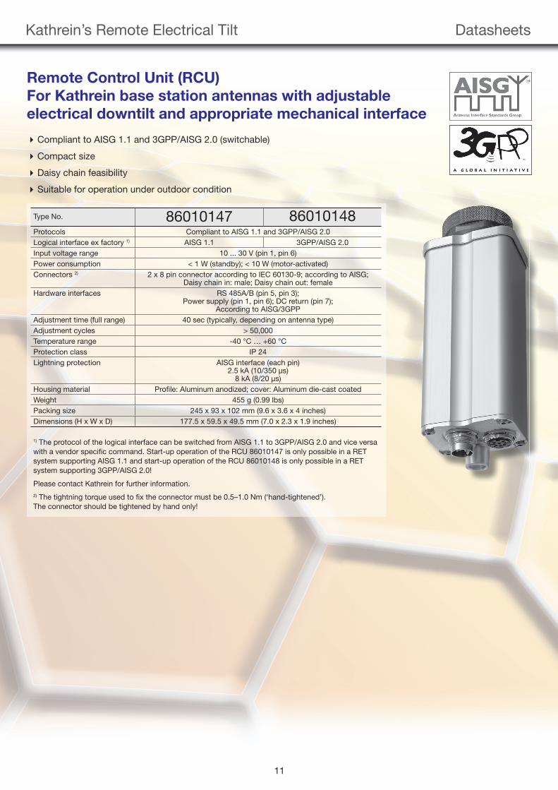
1) The protocol of the logical interface can be switched from AISG 1.1 to 3GPP/AISG 2.0 and vice versa with a vendor specifi c command. Start-up operation of the RCU 86010147 is only possible in a RET system supporting AISG 1.1 and start-up operation of the RCU 86010148 is only possible in a RET system supporting 3GPP/AISG 2.0!
Please contact Kathrein for further information.2) The tightning torque used to fi x the connector must be 0.5–1.0 Nm (‘hand-tightened’). The connector should be tightened by hand only!
Type No. 86010147 86010148Protocols Compliant to AISG 1.1 and 3GPP/AISG 2.0Logical interface ex factory 1) AISG 1.1 3GPP/AISG 2.0Input voltage range 10 ... 30 V (pin 1, pin 6)Power consumption < 1 W (standby); < 10 W (motor-activated)Connectors 2) 2 x 8 pin connector according to IEC 60130-9; according to AISG;
Daisy chain in: male; Daisy chain out: femaleHardware interfaces RS 485A/B (pin 5, pin 3);
Power supply (pin 1, pin 6); DC return (pin 7);According to AISG/3GPP
Adjustment time (full range) 40 sec (typically, depending on antenna type)Adjustment cycles > 50,000Temperature range -40 °C … +60 °CProtection class IP 24Lightning protection AISG interface (each pin)
2.5 kA (10/350 μs)8 kA (8/20 μs)
Housing material Profi le: Aluminum anodized; cover: Aluminum die-cast coatedWeight 455 g (0.99 lbs)Packing size 245 x 93 x 102 mm (9.6 x 3.6 x 4 inches)Dimensions (H x W x D) 177.5 x 59.5 x 49.5 mm (7.0 x 2.3 x 1.9 inches)
Remote Control Unit (RCU)
For Kathrein base station antennas with adjustable
electrical downtilt and appropriate mechanical interface
Compliant to AISG 1.1 and 3GPP/AISG 2.0 (switchable)
Compact size
Daisy chain feasibility
Suitable for operation under outdoor condition
99811878_Remote.indd 1199811878_Remote.indd 11 16.05.2012 11:26:4416.05.2012 11:26:44
Kathrein’s Remote Electrical Tilt Datasheets
12
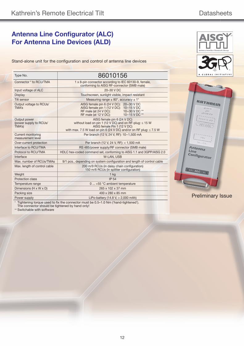
Antenna Line Confi gurator (ALC)
For Antenna Line Devices (ALD)
Type No. 86010156Connector * to RCU/TMA 1 x 8-pin connector according to IEC 60130-9, female,
conforming to AISG RF-connector (SMB male)Input voltage of ALC 20–30 V DCDisplay Touchscreen, sunlight visible, impact resistantTilt sensor Measuring range ± 80°, accuracy ± 1°Output voltage to RCUs/TMA’s
AISG female pin 6 (24 V DC): 20–30 V DCAISG female pin 1 (12 V DC): 10–15 V DCRF male (at 24 V DC): 10–30 V DC **RF male (at 12 V DC): 10–15 V DC **
Output power(power supply to RCUs/TMA’s)
AISG female pin 6 (24 V DC) without load on pin 1 (12 V DC) and on RF-plug: ≤ 15 W
AISG female Pin 1 (12 V DC) with max. 7.5 W load on pin 6 (24 V DC) and/or on RF plug: ≤ 7.5 W
Current monitoring measurement level
Per branch (12 V, 24 V, RF): 10–1,500 mA
Over-current protection Per branch (12 V, 24 V, RF): < 1,500 mAInterface to RCU/TMA RS 485/power supply/RF connector (SMB male)Protocol to RCU/TMA HDLC hex-coded command set, conforming to AISG 1.1 and 3GPP/AISG 2.0Interface W-LAN, USBMax. number of RCUs/TMAs 9/1 pcs., depending on system confi guration and length of control cableMax. length of control cable 200 m/9 RCUs (in daisy chain confi guration)
150 m/6 RCUs (in splitter confi guration)Weight 1 kgProtection class IP 54Temperature range 0 ... +55 °C ambient temperatureDimensions (H x W x D) 265 x 102 x 37 mmPacking size 400 x 280 x 85 mmPower supply LiPo-battery (14.8 V, > 2,000 mAh)* Tightening torque used to fi x the connector must be 0.5–1.0 Nm (‘hand-tightened’).
The connector should be tightened by hand only!** Switchable with software
Preliminary Issue
Stand-alone unit for the configuration and control of antenna line devices
99811878_Remote.indd 1299811878_Remote.indd 12 16.05.2012 11:26:4816.05.2012 11:26:48
Kathrein’s Remote Electrical Tilt Datasheets
13
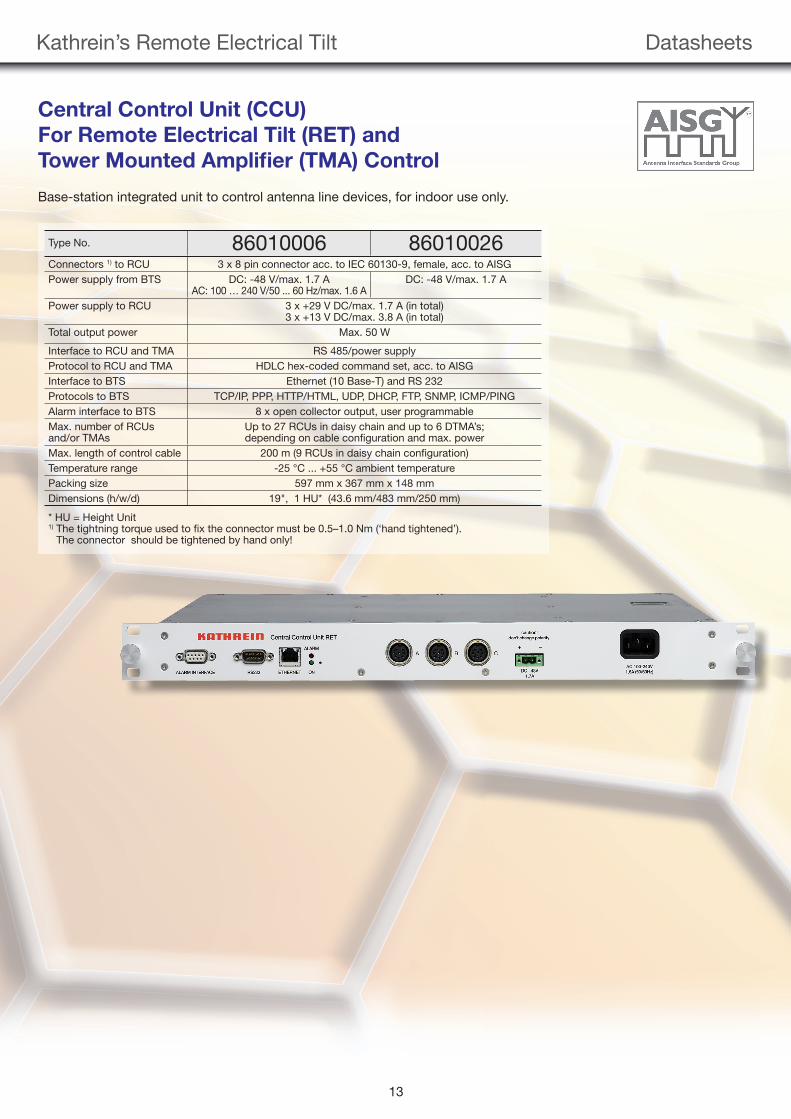
Central Control Unit (CCU)
For Remote Electrical Tilt (RET) and
Tower Mounted Amplifi er (TMA) Control
Type No. 86010006 86010026Connectors 1) to RCU 3 x 8 pin connector acc. to IEC 60130-9, female, acc. to AISGPower supply from BTS DC: -48 V/max. 1.7 A
AC: 100 … 240 V/50 ... 60 Hz/max. 1.6 ADC: -48 V/max. 1.7 A
Power supply to RCU 3 x +29 V DC/max. 1.7 A (in total)3 x +13 V DC/max. 3.8 A (in total)
Total output power Max. 50 W
Interface to RCU and TMA RS 485/power supplyProtocol to RCU and TMA HDLC hex-coded command set, acc. to AISGInterface to BTS Ethernet (10 Base-T) and RS 232Protocols to BTS TCP/IP, PPP, HTTP/HTML, UDP, DHCP, FTP, SNMP, ICMP/PINGAlarm interface to BTS 8 x open collector output, user programmableMax. number of RCUsand/or TMAs
Up to 27 RCUs in daisy chain and up to 6 DTMA’s; depending on cable confi guration and max. power
Max. length of control cable 200 m (9 RCUs in daisy chain confi guration)Temperature range -25 °C ... +55 °C ambient temperaturePacking size 597 mm x 367 mm x 148 mmDimensions (h/w/d) 19", 1 HU* (43.6 mm/483 mm/250 mm)
* HU = Height Unit1) The tightning torque used to fi x the connector must be 0.5–1.0 Nm (‘hand tightened’).
The connector should be tightened by hand only!
Base-station integrated unit to control antenna line devices, for indoor use only.
99811878_Remote.indd 1399811878_Remote.indd 13 16.05.2012 11:26:5316.05.2012 11:26:53
Kathrein’s Remote Electrical Tilt Datasheets
14
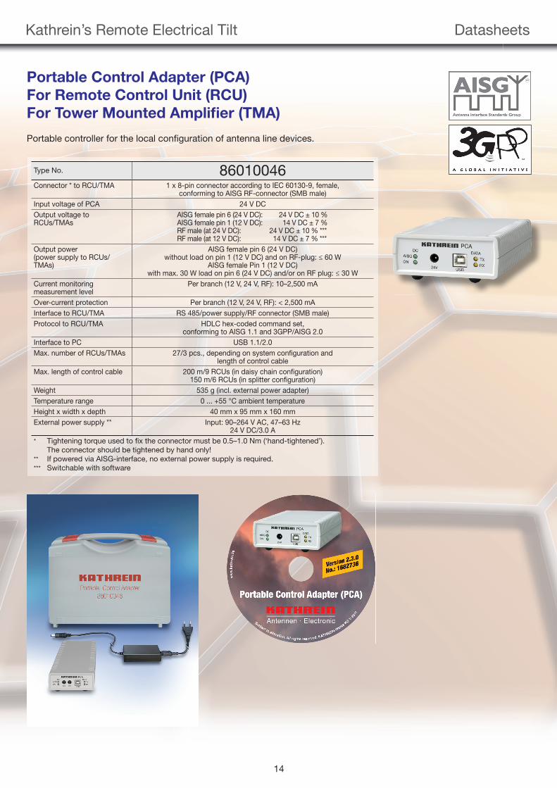
Portable Control Adapter (PCA)
For Remote Control Unit (RCU)
For Tower Mounted Amplifi er (TMA)
Type No. 86010046Connector * to RCU/TMA 1 x 8-pin connector according to IEC 60130-9, female,
conforming to AISG RF-connector (SMB male)Input voltage of PCA 24 V DCOutput voltage to RCUs/TMAs
AISG female pin 6 (24 V DC): 24 V DC ± 10 %AISG female pin 1 (12 V DC): 14 V DC ± 7 %RF male (at 24 V DC): 24 V DC ± 10 % ***RF male (at 12 V DC): 14 V DC ± 7 % ***
Output power(power supply to RCUs/TMAs)
AISG female pin 6 (24 V DC) without load on pin 1 (12 V DC) and on RF-plug: ≤ 60 W
AISG female Pin 1 (12 V DC) with max. 30 W load on pin 6 (24 V DC) and/or on RF plug: ≤ 30 W
Current monitoring measurement level
Per branch (12 V, 24 V, RF): 10–2,500 mA
Over-current protection Per branch (12 V, 24 V, RF): < 2,500 mAInterface to RCU/TMA RS 485/power supply/RF connector (SMB male)Protocol to RCU/TMA HDLC hex-coded command set,
conforming to AISG 1.1 and 3GPP/AISG 2.0Interface to PC USB 1.1/2.0Max. number of RCUs/TMAs 27/3 pcs., depending on system confi guration and
length of control cableMax. length of control cable 200 m/9 RCUs (in daisy chain confi guration)
150 m/6 RCUs (in splitter confi guration)Weight 535 g (incl. external power adapter) Temperature range 0 ... +55 °C ambient temperatureHeight x width x depth 40 mm x 95 mm x 160 mmExternal power supply ** Input: 90–264 V AC, 47–63 Hz
24 V DC/3.0 A* Tightening torque used to fi x the connector must be 0.5–1.0 Nm (‘hand-tightened’). The connector should be tightened by hand only!** If powered via AISG-interface, no external power supply is required. *** Switchable with software
Portable controller for the local confi guration of antenna line devices.
99811878_Remote.indd 1499811878_Remote.indd 14 16.05.2012 11:26:5716.05.2012 11:26:57
Kathrein’s Remote Electrical Tilt Datasheets
15
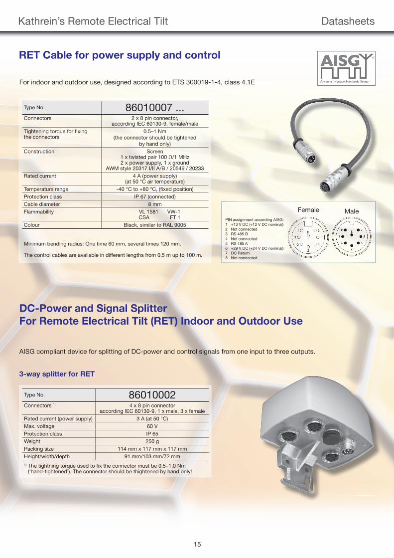
RET Cable for power supply and control
Type No. 86010007 ...Connectors 2 x 8 pin connector,
according IEC 60130-9, female/maleTightening torque for fi xingthe connectors
0.5–1 Nm(the connector should be tightened
by hand only)Construction Screen
1 x twisted pair 100 Ω/1 MHz2 x power supply, 1 x ground
AWM style 20317 I/II A/B / 20549 / 20233Rated current 4 A (power supply)
(at 50 °C air temperature)Temperature range -40 °C to +80 °C, (fi xed position)Protection class IP 67 (connected)Cable diameter 8 mmFlammability VL 1581 VW-1
CSA FT 1Colour Black, similar to RAL 9005
Minimum bending radius: One time 60 mm, several times 120 mm.
The control cables are available in different lengths from 0.5 m up to 100 m.
For indoor and outdoor use, designed according to ETS 300019-1-4, class 4.1E
PIN assignment according AISG:1 +13 V DC (+12 V DC nominal)2 Not connected3 RS 485 B4 Not connected5 RS 485 A6 +29 V DC (+24 V DC nominal)7 DC Return8 Not connected
Female Male
DC-Power and Signal Splitter
For Remote Electrical Tilt (RET) Indoor and Outdoor Use
Type No. 86010002Connectors 1) 4 x 8 pin connector
according IEC 60130-9, 1 x male, 3 x femaleRated current (power supply) 3 A (at 50 °C)Max. voltage 60 VProtection class IP 65Weight 250 gPacking size 114 mm x 117 mm x 117 mmHeight/width/depth 91 mm/103 mm/72 mm1) The tightning torque used to fi x the connector must be 0.5–1.0 Nm
(‘hand-tightened’). The connector should be thightened by hand only!
AISG compliant device for splitting of DC-power and control signals from one input to three outputs.
3-way splitter for RET
99811878_Remote.indd 1599811878_Remote.indd 15 16.05.2012 11:27:0816.05.2012 11:27:08
Kathrein’s Remote Electrical Tilt Datasheets
16
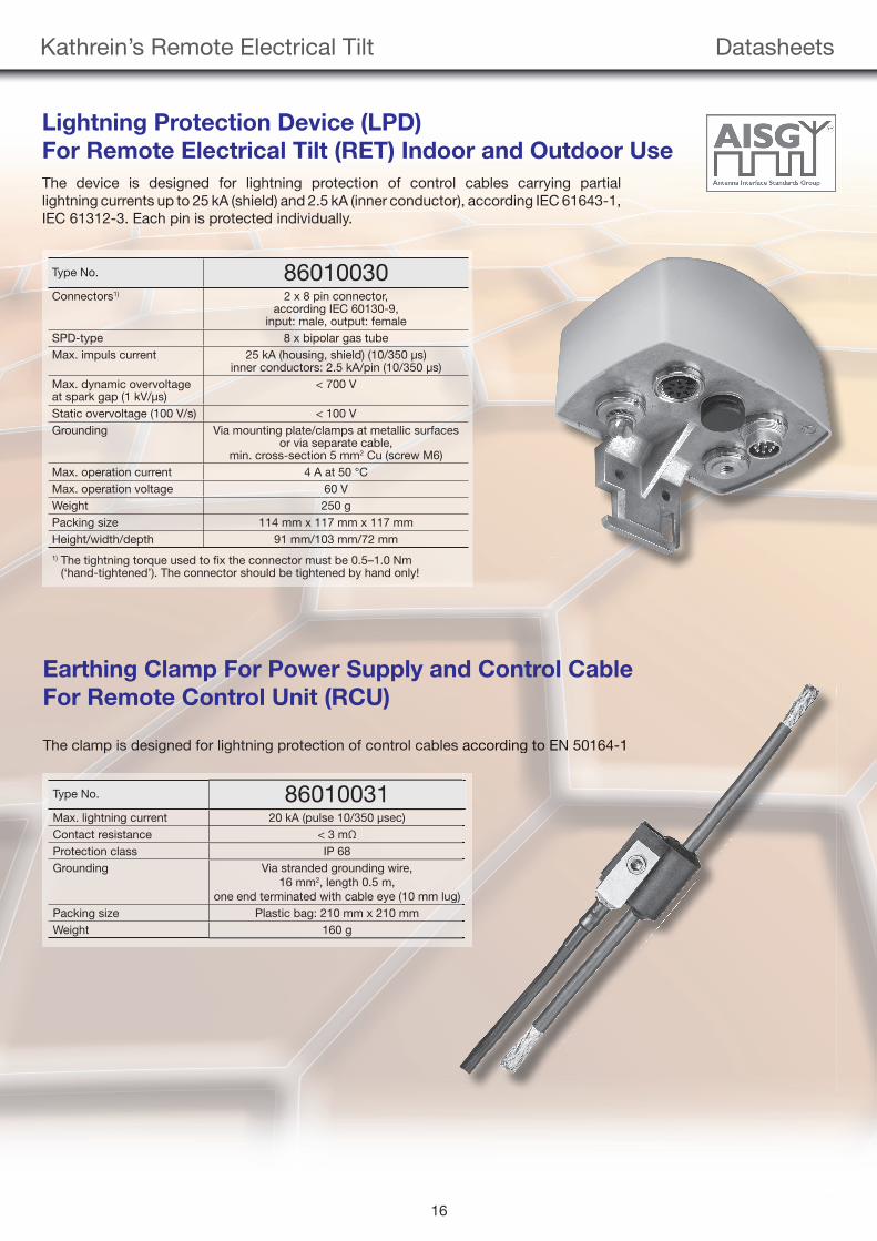
Lightning Protection Device (LPD)
For Remote Electrical Tilt (RET) Indoor and Outdoor Use
The device is designed for lightning protection of control cables carrying partiallightning currents up to 25 kA (shield) and 2.5 kA (inner conductor), according IEC 61643-1,IEC 61312-3. Each pin is protected individually.
Type No. 86010030Connectors1) 2 x 8 pin connector,
according IEC 60130-9,input: male, output: female
SPD-type 8 x bipolar gas tubeMax. impuls current 25 kA (housing, shield) (10/350 μs)
inner conductors: 2.5 kA/pin (10/350 μs)Max. dynamic overvoltageat spark gap (1 kV/μs)
< 700 V
Static overvoltage (100 V/s) < 100 VGrounding Via mounting plate/clamps at metallic surfaces
or via separate cable,min. cross-section 5 mm2 Cu (screw M6)
Max. operation current 4 A at 50 °CMax. operation voltage 60 VWeight 250 gPacking size 114 mm x 117 mm x 117 mmHeight/width/depth 91 mm/103 mm/72 mm1) The tightning torque used to fi x the connector must be 0.5–1.0 Nm
(‘hand-tightened’). The connector should be tightened by hand only!
Earthing Clamp For Power Supply and Control Cable
For Remote Control Unit (RCU)
The clamp is designed for lightning protection of control cables according to EN 50164-1
Type No. 86010031Max. lightning current 20 kA (pulse 10/350 μsec)Contact resistance < 3 mΩProtection class IP 68Grounding Via stranded grounding wire,
16 mm2, length 0.5 m,one end terminated with cable eye (10 mm lug)
Packing size Plastic bag: 210 mm x 210 mmWeight 160 g
accordinng to EEEENNNNNNNN 5011664-1
99811878_Remote.indd 1699811878_Remote.indd 16 16.05.2012 11:27:1416.05.2012 11:27:14
17
Kathrein’s Remote Electrical Tilt DTMAs
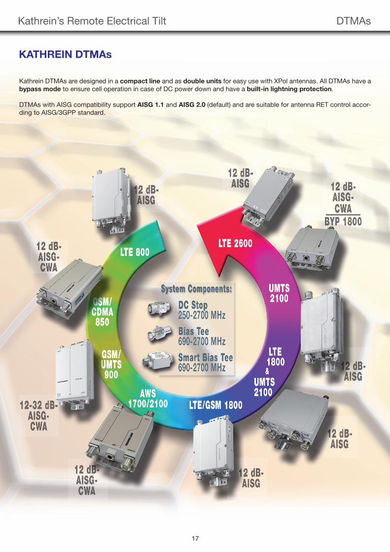
KATHREIN DTMAs
Kathrein DTMAs are designed in a compact line and as double units for easy use with XPol antennas. All DTMAs have a bypass mode to ensure cell operation in case of DC power down and have a built-in lightning protection.
DTMAs with AISG compatibility support AISG 1.1 and AISG 2.0 (default) and are suitable for antenna RET control accor-ding to AISG/3GPP standard.
99811878_Remote.indd 1799811878_Remote.indd 17 16.05.2012 11:27:2216.05.2012 11:27:22
18
Kathrein’s Remote Electrical Tilt DTMAs
Kathrein offers a big variety of different DTMA types with numerous features. The customer can choose an adequate DTMA according to the following characteristics:
1. Single mode (AISG or CWA) or dual mode (AISG and CWA) DTMA
2. Different gain values 12 dB
24 dB
12/32 dB (switchable)
3. Single-band and dual-band devices
4. Various frequency ranges 700 MHz range
800 MHz range
850 MHz range
900 MHz range
1,800 MHz range
1,900 MHz range
AWS
2,100 MHz range
2,600 MHz range
5. RF-bypass at different frequencies
For an up-to-date overview of all existing types, please see the TMA selection guide on our homepage.
99811878_Remote.indd 1899811878_Remote.indd 18 16.05.2012 11:27:2916.05.2012 11:27:29
For your notes
19
99811878_Remote.indd 1999811878_Remote.indd 19 16.05.2012 11:27:3116.05.2012 11:27:31

9981
1878
/6/0
512/
ZWD
/Pf T
echn
ical
dat
a su
bjec
t to
chan
ge. T
echn
ical
dat
a re
pre
sent
typ
ical
val
ues.
Internet: http://www.kathrein.de
KATHREIN-Werke KG · Phone +49 8031 184-0 · Fax +49 8031 184-973 Anton-Kathrein-Straße 1-3 · P.O. Box 10 04 44 · 83004 Rosenheim/GERMANY
For technical information, orders, catalogues or
CD-ROM, please contact:
99811878_Remote.indd 2099811878_Remote.indd 20 16.05.2012 11:27:3416.05.2012 11:27:34