research activities - kth
TRANSCRIPT
RESEARCH ACTIVITIES
Division of Heat and Power Technology
Infrastructure
Department of Energy Technology
KTH 2011
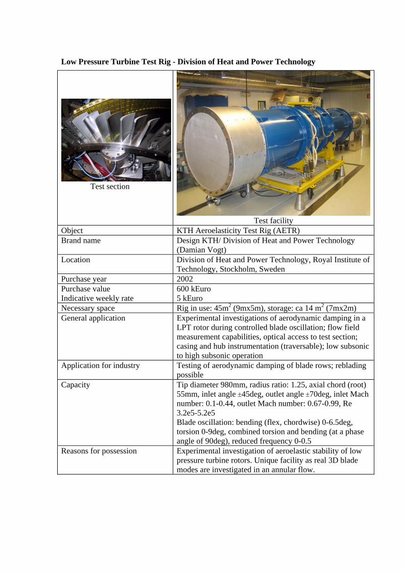
Low Pressure Turbine Test Rig - Division of Heat and Power Technology
Test section
Test facility Object KTH Aeroelasticity Test Rig (AETR) Brand name Design KTH/ Division of Heat and Power Technology
(Damian Vogt) Location Division of Heat and Power Technology, Royal Institute of
Technology, Stockholm, Sweden Purchase year 2002 Purchase value Indicative weekly rate
600 kEuro 5 kEuro
Necessary space Rig in use: 45m2 (9mx5m), storage: ca 14 m2 (7mx2m) General application Experimental investigations of aerodynamic damping in a
LPT rotor during controlled blade oscillation; flow field measurement capabilities, optical access to test section; casing and hub instrumentation (traversable); low subsonic to high subsonic operation
Application for industry Testing of aerodynamic damping of blade rows; reblading possible
Capacity Tip diameter 980mm, radius ratio: 1.25, axial chord (root) 55mm, inlet angle ±45deg, outlet angle ±70deg, inlet Mach number: 0.1-0.44, outlet Mach number: 0.67-0.99, Re 3.2e5-5.2e5 Blade oscillation: bending (flex, chordwise) 0-6.5deg, torsion 0-9deg, combined torsion and bending (at a phase angle of 90deg), reduced frequency 0-0.5
Reasons for possession
Experimental investigation of aeroelastic stability of low pressure turbine rotors. Unique facility as real 3D blade modes are investigated in an annular flow.
Current task volume Possible increases, Limitations
Reblading in 2009 within FUTURE Optical window for L2F measurements (2009)
Needs of investments - Normal instrumentation Steady-state pressure: PSI9016 (16 channels), PSI8400
(212 channels), taps on blades, hub and casing Time-resolved pressure: KULITE sensors (XCQ-062, XCQ-2-062, LQ-5-080), data sampling: KT8000 (Kayser-Threde) high-speed data acquisition system, 32 channels, 200kHz max sampling frequency, sensors on blades, hub and casing Steady-state temperature Aerodynamic probes (4-hole) Bowed plexiglass window (low-tech flow viz) Data acquisition and rig control: LabView Blade oscillation: Laser vibrometer on oscillating blade
Loading Availability
80% usage (TurboVib project, FUTURE project)
Responsible persons Damian Vogt (KTH)
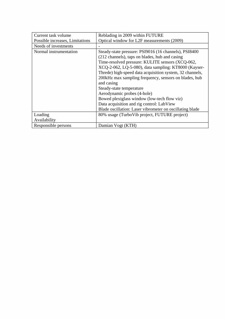
Test Turbine - Division of Heat and Power Technology
Object Cold Flow Test Turbine Brand name ABB STAL design Location Division of Heat and Power Technology, Royal Institute of
Technology, Stockholm, Sweden Purchase year 1984 Purchase value Indicative weekly rate
1250 kEuro (1984) Depending on the length of the project
Necessary space ca 30 m2. General application Performance tests of turbine stages, both gas and steam
turbines. Efficiency measurements and detailed investigation of intrastage flow parameters.
Application for industry Used to investigate new blading for turbines, secondary flows, investigation of cooling/bleeding flows.
Capacity Number of stages 1-3, min. inner diameter 280 mm, max. outer diameter 600 mm and max. speed 9000 rpm. Max capacity; flow: 4,7 kg/s, p_in: 4 bar (abs), t_in: 25-90°C. Cavity leakage flows (inflow or outflow).
Reasons for possession
The test turbine is a unique facility for development of turbine blading. The facility is a joint venture between KTH and Siemens Industrial Turbomachinery AB, Sweden.
Current task volume Possible increases, Limitations
Presently about two measurement campaigns per year. An increase in volume is possible with 1-2 campaigns.
Needs of investments No direct need, all systems in operation. For continuous runs (>30 min) at higher than 7500 rpm a service/upgrading of bearing system is needed. Outlaid upgrading exists for speeds up to 13000rpm (~100 kEuro)
Normal instrumentation LabView as data acquisition system, Pressure (PSI System 9010): 96 channels, Temperature (Datascan): 40 channels. For steady and unsteady flow field investigations: Various probes. Shaft- and bearing friction torque, rotational speed etc. Rotating measurement system (slip rings 36 circuits).
Loading Availability
40% 60%
Annula
Object Brand nLocation
PurchasPurchasIndicativNecessaGeneral
Applica
Capacity
Reasons
Current Possible
ar Sector
name n
e year e value ve weekly ratary space l application
ation for indus
y
s for possessio
task volume e increases, L
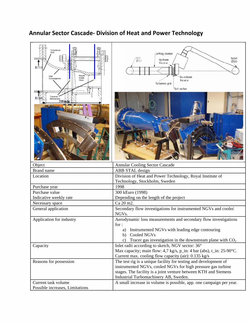
Cascade‐
te
stry
on
imitations
‐ Division
AADT13DCSNAfo
InMCTinsInA
n of Heat
Annular CooliABB STAL dDivision of HeTechnology, S
998 300 kEuro (19Depending onCa 20 m2. Secondary flowNGVs. Aerodynamic for :
a) Instrub) Coolec) Tracer
nlet radii accoMax capacity;Current max. cThe test rig is nstrumented Ntages. The facndustrial Turb
A small increa
and Pow
ing Sector Caesign eat and PoweStockholm, Sw
998) n the length of
w investigatio
loss measure
umented NGVed NGVs r gas investigording to sket; main flow: 4cooling flow a unique faci
NGVs, cooledcility is a joinbomachinery ase in volume
wer Techn
ascade
er Technologyweden
f the project
ons for instru
ements and se
Vs with leadin
gation in the dtch, NGV sec4,7 kg/s, p_incapacity (air)
ility for testind NGVs for hnt venture bet
y AB, Swedene is possible, a
nology
y, Royal Instit
umented NGV
econdary flow
ng edge conto
downstream pctor: 36° n: 4 bar (abs), ): 0.135 kg/s
ng and develohigh pressure tween KTH ann. app. one cam
tute of
Vs and cooled
w investigation
ouring
plane with CO
t_in: 25-90°C
opment of gas turbine nd Siemens
mpaign per yea
d
ns
O2
C.
ar.
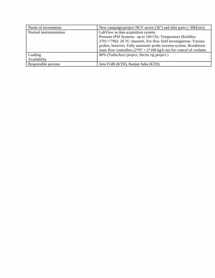
Needs of investments New campaign/project NGV sector (36°) and inlet parts (~30kEuro) Normal instrumentation LabView as data acquisition system,
Pressure (PSI Systems: up to 160 Ch): Temperature (Keithley 2701+7706): 20 TC channels. For flow field investigations: Various probes, hotwires. Fully automatic probe traverse system. Bronkhorst mass flow controllers (2*97 + 2*180 kg/h air) for control of coolants.
Loading Availability
80% (TurboAero project, Sector rig project )
Responsible persons Jens Fridh (KTH), Ranjan Saha (KTH)
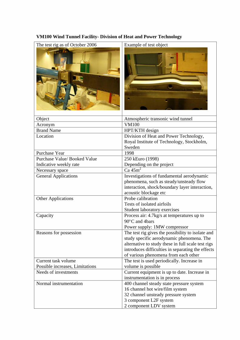
VM100 Wind Tunnel Facility- Division of Heat and Power Technology
The test rig as of October 2006 Example of test object
Object Atmospheric transonic wind tunnel Acronym VM100 Brand Name HPT/KTH design Location Division of Heat and Power Technology,
Royal Institute of Technology, Stockholm, Sweden
Purchase Year 1998 Purchase Value/ Booked Value Indicative weekly rate
250 kEuro (1998) Depending on the project
Necessary space Ca 45m2 General Applications Investigations of fundamental aerodynamic
phenomena, such as steady/unsteady flow interaction, shock/boundary layer interaction, acoustic blockage etc
Other Applications Probe calibration Tests of isolated airfoils Student laboratory exercises
Capacity Process air: 4.7kg/s at temperatures up to 90°C and 4bars Power supply: 1MW compressor
Reasons for possession
The test rig gives the possibility to isolate and study specific aerodynamic phenomena. The alternative to study these in full scale test rigs introduces difficulties in separating the effects of various phenomena from each other
Current task volume Possible increases, Limitations
The test is used periodically. Increase in volume is possible
Needs of investments Current equipment is up to date. Increase in instrumentation is in process
Normal instrumentation 400 channel steady state pressure system 16 channel hot wire/film system 32 channel unsteady pressure system 3 component L2F system 2 component LDV system
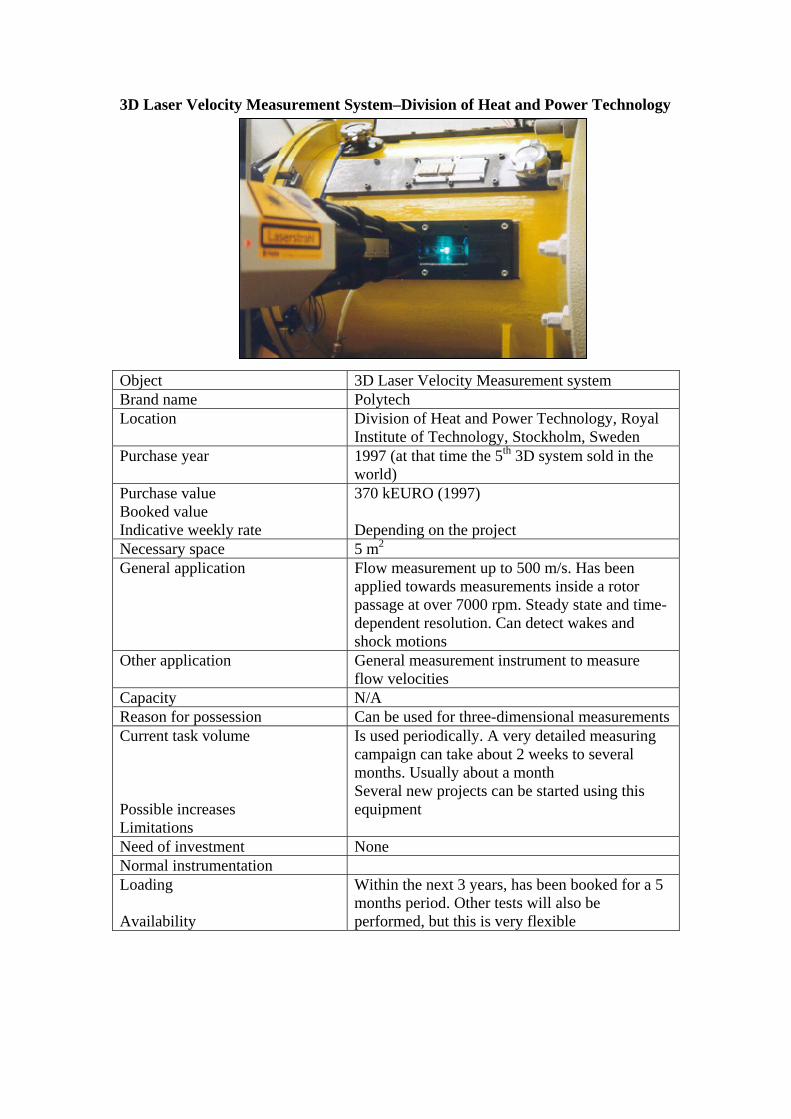
3D Laser Velocity Measurement System–Division of Heat and Power Technology Object 3D Laser Velocity Measurement system Brand name Polytech Location Division of Heat and Power Technology, Royal
Institute of Technology, Stockholm, Sweden Purchase year 1997 (at that time the 5th 3D system sold in the
world) Purchase value Booked value Indicative weekly rate
370 kEURO (1997) Depending on the project
Necessary space 5 m2 General application Flow measurement up to 500 m/s. Has been
applied towards measurements inside a rotor passage at over 7000 rpm. Steady state and time-dependent resolution. Can detect wakes and shock motions
Other application General measurement instrument to measure flow velocities
Capacity N/A Reason for possession Can be used for three-dimensional measurements Current task volume Possible increases Limitations
Is used periodically. A very detailed measuring campaign can take about 2 weeks to several months. Usually about a month Several new projects can be started using this equipment
Need of investment None Normal instrumentation Loading Availability
Within the next 3 years, has been booked for a 5 months period. Other tests will also be performed, but this is very flexible
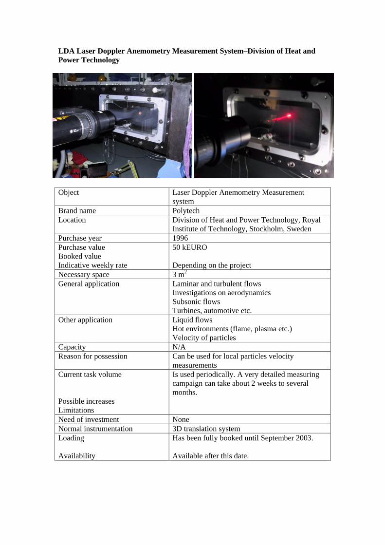
LDA Laser Doppler Anemometry Measurement System–Division of Heat and Power Technology
Object Laser Doppler Anemometry Measurement
system Brand name Polytech Location Division of Heat and Power Technology, Royal
Institute of Technology, Stockholm, Sweden Purchase year 1996 Purchase value Booked value Indicative weekly rate
50 kEURO Depending on the project
Necessary space 3 m2 General application Laminar and turbulent flows
Investigations on aerodynamics Subsonic flows Turbines, automotive etc.
Other application Liquid flows Hot environments (flame, plasma etc.) Velocity of particles
Capacity N/A Reason for possession Can be used for local particles velocity
measurements Current task volume Possible increases Limitations
Is used periodically. A very detailed measuring campaign can take about 2 weeks to several months.
Need of investment None Normal instrumentation 3D translation system Loading Availability
Has been fully booked until September 2003. Available after this date.
Remote C
Object Brand namLocation
Purchase yPurchase vIndicative Necessary General ap
ApplicatioCapacity
Reasons fo
Current tasPossible inNeeds of in
Normal ins
Loading AResponsib
ontrolled C
me
year value weekly ratespace
pplication
on for industr
or possession
sk volume ncreases, Limnvestments
strumentatio
Availability le persons
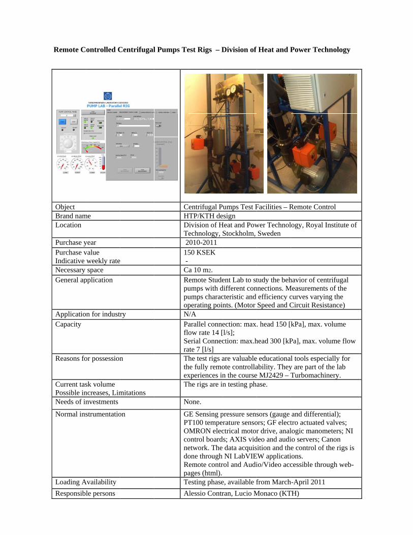
Centrifugal
e
ry
n
mitations
on
l Pumps Te
CHDT 215 -CRpupuopNPafloSeraThthexTh
N
GPTOconedoRpaTA
est Rigs – D
entrifugal PHTP/KTH deDivision of H
echnology, 2010-2011 50 KSEK
a 10 m2. Remote Stude
umps with dumps characperating poin
N/A arallel conneow rate 14 [erial Connecate 7 [l/s] he test rigs a
he fully remoxperiences inhe rigs are in
None.
GE Sensing pT100 tempe
OMRON elecontrol boardetwork. Theone through
Remote contrages (html).esting phase
Alessio Contr
Division of
umps Test Fesign Heat and PowStockholm,
ent Lab to stdifferent concteristic and nts. (Motor
ection: max[l/s]; ction: max.h
are valuableote controllan the coursen testing ph
pressure senserature sensoctrical motor
ds; AXIS vid data acquisNI LabVIE
rol and Audi
e, available fran, Lucio M
f Heat and P
Facilities – R
wer TechnolSweden
tudy the behnnections. M
efficiency cSpeed and C
. head 150 [k
head 300 [kP
e educationalability. Theye MJ2429 – Tase.
sors (gauge ors; GF electr drive, anal
deo and audisition and theEW applicatiio/Video acc
from MarchMonaco (KT
Power Tech
Remote Con
logy, Royal
havior of cenMeasurement
curves varyiCircuit Resis
kPa], max. v
Pa], max. vo
l tools especy are part of Turbomachi
and differentro actuated logic manomio servers; Ce control of ions. cessible thro
h-April 2011TH)
hnology
ntrol
Institute of
ntrifugal ts of the ng the stance)
volume
olume flow
cially for the lab inery.
ntial); valves;
meters; NI Canon
the rigs is
ough web-
Remot
Object Location
PurchasPurchasIndicativNecessaGeneral
Applica
Capacity
Reasons
Current PossibleNeeds o
Normal
LoadingAvailabRespons
te Linear
n
e year e value ve weekly ratary space l application
ation for indus
y
s for possessio
task volume e increases, Lof investments
instrumentati
g ility sible persons
Cascade
te
stry
on
imitations s
ion
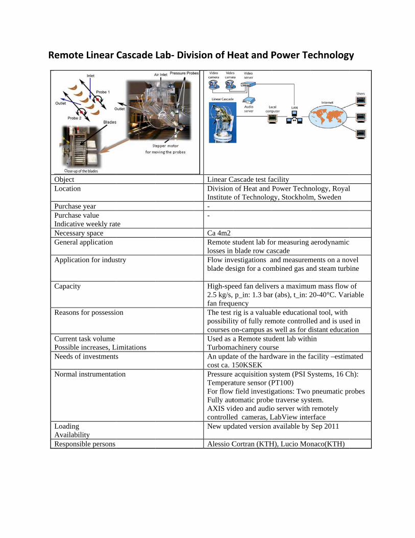
Lab‐ Division of H
Linear CDivisionInstitute - -
Ca 4m2 Remote slosses in Flow invblade des High-spe2.5 kg/s, fan frequThe test possibilitcourses oUsed as aTurbomaAn updatcost ca. 1PressureTemperaFor flowFully autAXIS vidcontrolleNew upd Alessio C
Heat and P
Cascade test fan of Heat and
of Technolog
student lab fon blade row cavestigations asign for a com
eed fan delive p_in: 1.3 bar
uency rig is a valuabty of fully remon-campus asa Remote stuachinery courate of the hard150KSEK acquisition s
ature sensor (Pw field investig
tomatic probedeo and audioed cameras, Ldated version
Cortran (KTH
Power Te
acility Power Techngy, Stockholm
or measuring ascade and measuremmbined gas an
ers a maximur (abs), t_in: 2
ble educationmote controlls well as for dudent lab withrse dware in the f
system (PSI SPT100) gations: Two e traverse syso server with LabView inteavailable by
H), Lucio Mon
echnology
nology, Royalm, Sweden
aerodynamic
ments on a nond steam turb
m mass flow20-40°C. Var
nal tool, with ed and is used
distant educathin
facility –estim
Systems, 16 C
pneumatic prtem. remotely rface Sep 2011
naco(KTH)
y
l
vel bine
of riable
d in tion
mated
Ch):
robes
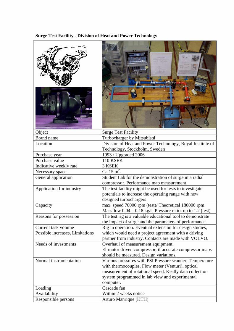
Surge Test Facility - Division of Heat and Power Technology
Object Surge Test Facility Brand name Turbocharger by Mitsubishi Location Division of Heat and Power Technology, Royal Institute of
Technology, Stockholm, Sweden Purchase year 1993 / Upgraded 2006 Purchase value Indicative weekly rate
110 KSEK 3 KSEK
Necessary space Ca 15 m2. General application Student Lab for the demonstration of surge in a radial
compressor. Performance map measurement. Application for industry The test facility might be used for tests to investigate
potentials to increase the operating range with new designed turbochargers
Capacity max. speed 70000 rpm (test)/ Theoretical 180000 rpm Massflow 0.04 – 0.18 kg/s, Pressure ratio: up to 1.2 (test)
Reasons for possession
The test rig is a valuable educational tool to demonstrate the impact of surge and the parameters of performance.
Current task volume Possible increases, Limitations
Rig in operation. Eventual extension for design studies, which would need a project agreement with a driving partner from industry. Contacts are made with VOLVO.
Needs of investments Overhaul of measurement equipment. El-motor driven compressor, if accurate compressor maps should be measured. Design variations.
Normal instrumentation Various pressures with PSI Pressure scanner, Temperature with thermocouples. Flow meter (Venturi), optical measurement of rotational speed. Keatly data collection system programmed in lab view and experimental computer.
Loading Availability
Cascade fan Within 2 weeks notice
Responsible persons Arturo Manrique (KTH)

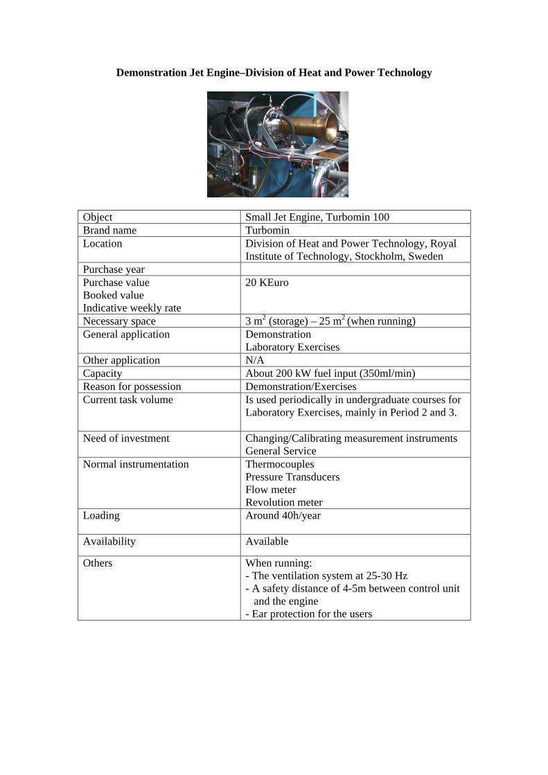
Demonstration Jet Engine–Division of Heat and Power Technology
Object Small Jet Engine, Turbomin 100 Brand name Turbomin Location Division of Heat and Power Technology, Royal
Institute of Technology, Stockholm, Sweden Purchase year Purchase value Booked value Indicative weekly rate
20 KEuro
Necessary space 3 m2 (storage) – 25 m2 (when running) General application Demonstration
Laboratory Exercises Other application N/A Capacity About 200 kW fuel input (350ml/min) Reason for possession Demonstration/Exercises Current task volume Is used periodically in undergraduate courses for
Laboratory Exercises, mainly in Period 2 and 3.
Need of investment Changing/Calibrating measurement instruments General Service
Normal instrumentation Thermocouples Pressure Transducers Flow meter Revolution meter
Loading Around 40h/year
Availability Available
Others When running: - The ventilation system at 25-30 Hz - A safety distance of 4-5m between control unit and the engine - Ear protection for the users

Hot Wire/Film Anemometer – Division of Heat and Power Technology
The Anemometer System as of May 1998 Example of HF sensors mounted on airfoil
Object Hot Wire/Film Anemometer Brand Name TSI Location Division of Heat and Power Technology,
Royal Institute of Technology, Stockholm, Sweden
Purchase Year 1996 Purchase Value Booked Value Rental cost, weekly rate
60 kEuro (1996)
Necessary space Ca 2m2 General Applications Investigations of fundamental aerodynamic
phenomena, such as boundary layer behaviour, transition and separation development, turbulence, steady/unsteady flow interaction, shock/boundary layer interaction, etc
Other Applications Probe calibration Student laboratory excercises
Capacity 16 channels with simultaneous data aqcuisition 1MHz total sampling speed 50 kHz max sampling speed per channel
Reasons for possession Consequences of liquidation
The equipment gives the possibility to study detailed boundary layer phenomena. The alternative to study these with laser (LDA, L2F, PIV) equipment provides difficulties in resolving the boundary layers due to the larger measurement volume
Current task volume Possible increases
The equipment is used periodically. Increase in volume is possible
Needs of investments Current equipment is up to date. Normal instrumentation Loading Availability
Not high In % of time (available for other tests than today planned)

Unsteady Pressure Measurement System - Division of Heat and Power Technology
XCQ-062 transducer
LQ-080 transducer
Data Acquisition System KT8000
Object Unsteady Pressure Measurement System Brand name Data acquisition system: KT8000
Pressure transducers: KULITE (different types) Location Division of Heat and Power Technology, Royal Institute of
Technology, Stockholm, Sweden Purchase year 2000 Purchase value Indicative weekly rate
Data acquisition system with 40 sensors: 125kEuro (2000)
Necessary space 2m2 General application High-speed data acquisition system for Wheatstone-bridge
sensing (+-5V symmetric excitation), currently use with KULITE sensors for unsteady pressure measurements at high frequencies (32 channels up to 200kHz sampled)
Other application Any other time-resolved measurements with respective transducer (Wheatstone bridge, 5V symmetric excitation) such as strain gauges
Capacity 32 channels, max parallel sampling rate 200kHz 4 thermocouple inputs (type K) Programmable signal amplification and low-pass filters for each channel,PC based control program, PC operation system WIN-NT, PC mounted in rack
Reasons for possession
Measurement system allows investigating unsteady phenomena at high frequencies. It will be used to study aeroelastic phenomena and transition under fluctuating back pressure.
Current Task Volume Possible increases, Limitations
Currently used in studying transition and aeroelastic phenomena.
Normal instrumentation Industrial PC (NT4) and data acquisition software Estimated Usage Costs 28 Euro/h Responsible persons Damian Vogt (KTH)
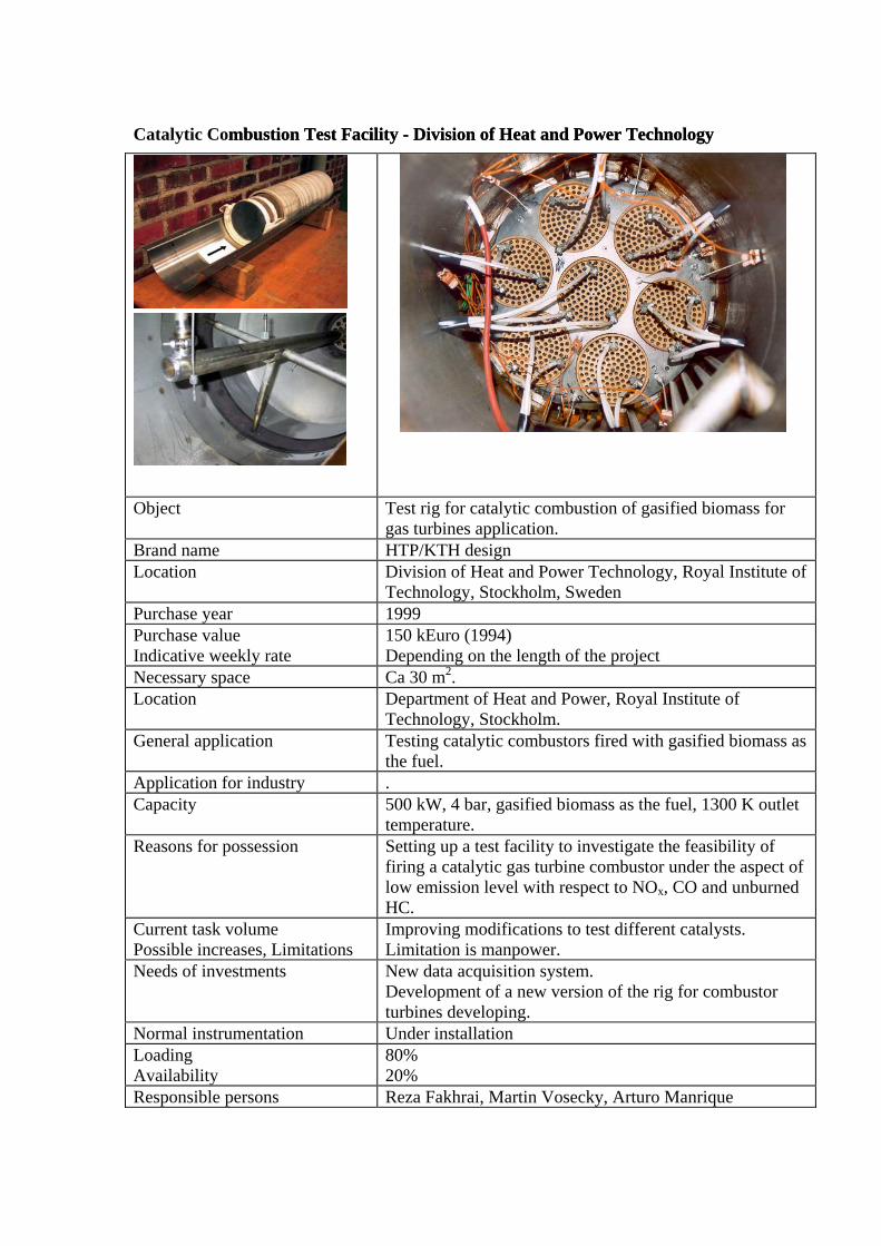
Catalytic Combustion Test Facility - Division of Heat and Power Technology mbustion Test Facility - Division of Heat and Power Technology
Object Test rig for catalytic combustion of gasified biomass for gas turbines application.
Brand name HTP/KTH design Location Division of Heat and Power Technology, Royal Institute of
Technology, Stockholm, Sweden Purchase year 1999 Purchase value Indicative weekly rate
150 kEuro (1994) Depending on the length of the project
Necessary space Ca 30 m2. Location Department of Heat and Power, Royal Institute of
Technology, Stockholm. General application Testing catalytic combustors fired with gasified biomass as
the fuel. Application for industry . Capacity 500 kW, 4 bar, gasified biomass as the fuel, 1300 K outlet
temperature. Reasons for possession
Setting up a test facility to investigate the feasibility of firing a catalytic gas turbine combustor under the aspect of low emission level with respect to NOx, CO and unburned HC.
Current task volume Possible increases, Limitations
Improving modifications to test different catalysts. Limitation is manpower.
Needs of investments New data acquisition system. Development of a new version of the rig for combustor turbines developing.
Normal instrumentation Under installation Loading Availability
80% 20%
Responsible persons Reza Fakhrai, Martin Vosecky, Arturo Manrique
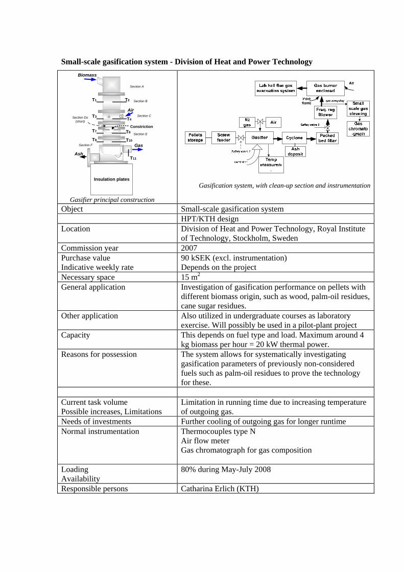
Small-scale gasification system - Division of Heat and Power Technology
Ash
Air
T1
T3
T2
T4
Biomass
Insulation plates
Constriction
Gas
T7 T8
T10
T11
T9
Section A
Section B
Section CSection Ds (short)
Section E
Section F
Gasifier principal construction
Gasification system, with clean-up section and instrumentation
Object Small-scale gasification system HPT/KTH design Location Division of Heat and Power Technology, Royal Institute
of Technology, Stockholm, Sweden Commission year 2007 Purchase value Indicative weekly rate
90 kSEK (excl. instrumentation) Depends on the project
Necessary space 15 m2 General application Investigation of gasification performance on pellets with
different biomass origin, such as wood, palm-oil residues, cane sugar residues.
Other application Also utilized in undergraduate courses as laboratory exercise. Will possibly be used in a pilot-plant project
Capacity This depends on fuel type and load. Maximum around 4 kg biomass per hour = 20 kW thermal power.
Reasons for possession
The system allows for systematically investigating gasification parameters of previously non-considered fuels such as palm-oil residues to prove the technology for these.
Current task volume Possible increases, Limitations
Limitation in running time due to increasing temperature of outgoing gas.
Needs of investments Further cooling of outgoing gas for longer runtime Normal instrumentation Thermocouples type N
Air flow meter Gas chromatograph for gas composition
Loading Availability
80% during May-July 2008
Responsible persons Catharina Erlich (KTH)
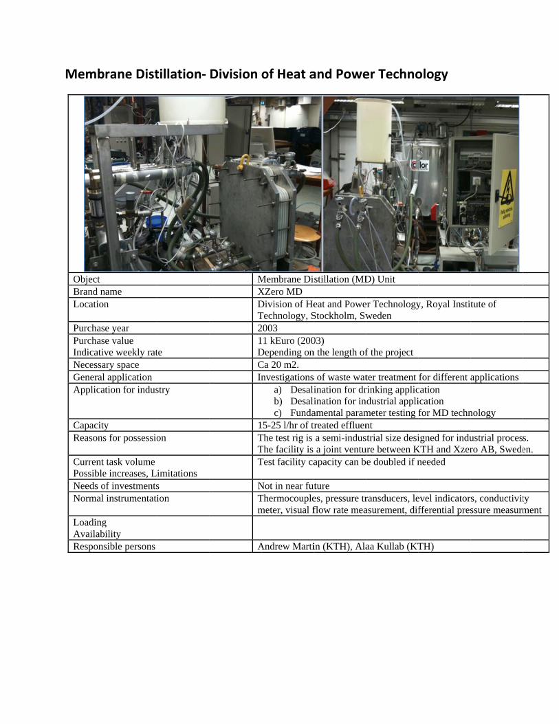
Memb
Object Brand nLocation
PurchasPurchasIndicativNecessaGeneralApplica
CapacityReasons
Current PossibleNeeds oNormal
LoadingAvailabRespons
rane Dist
name n
e year e value ve weekly ratary space l application ation for indus
y s for possessio
task volume e increases, Lof investments
instrumentati
g ility sible persons
tillation‐
te
stry
on
imitations s ion
Division
MXDT21DCIn
1TTT
NTm
A
of Heat a
Membrane DiXZero MD Division of HeTechnology, S2003
1 kEuro (200Depending onCa 20 m2. nvestigations
a) Desalib) Desalic) Funda
5-25 l/hr of trThe test rig is The facility is Test facility ca
Not in near futThermocouplemeter, visual f
Andrew Marti
and Powe
stillation (MD
eat and PoweStockholm, Sw
03) n the length of
s of waste watination for drination for inamental paramtreated effluena semi-indusa joint ventu
apacity can b
uture es, pressure trflow rate mea
in (KTH), Ala
er Techno
D) Unit
er Technologyweden
f the project
ter treatment rinking applicndustrial applimeter testing nt strial size desiure between Kbe doubled if n
ransducers, leasurement, dif
aa Kullab (KT
ology
y, Royal Instit
for different acation ication for MD techn
igned for induKTH and Xzerneeded
evel indicatorfferential pres
TH)
tute of
applications
nology
ustrial procesro AB, Swede
s, conductivitssure measurm
s. en.
ty ment
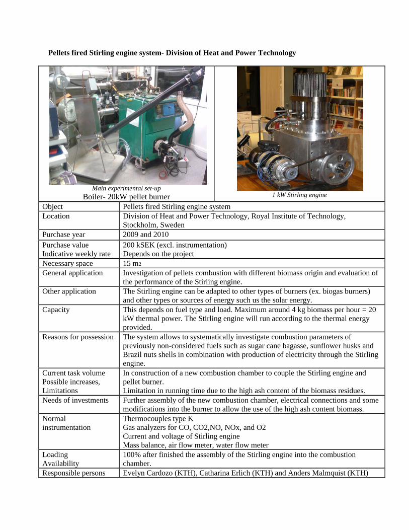
Pellets fired Stirling engine system- Division of Heat and Power Technology
Main experimental set-up
Boiler- 20kW pellet burner
1 kW Stirling engine
Object Pellets fired Stirling engine system Location Division of Heat and Power Technology, Royal Institute of Technology,
Stockholm, Sweden Purchase year 2009 and 2010 Purchase value Indicative weekly rate
200 kSEK (excl. instrumentation) Depends on the project
Necessary space 15 m2
General application Investigation of pellets combustion with different biomass origin and evaluation of the performance of the Stirling engine.
Other application The Stirling engine can be adapted to other types of burners (ex. biogas burners) and other types or sources of energy such us the solar energy.
Capacity This depends on fuel type and load. Maximum around 4 kg biomass per hour = 20 kW thermal power. The Stirling engine will run according to the thermal energy provided.
Reasons for possession The system allows to systematically investigate combustion parameters of previously non-considered fuels such as sugar cane bagasse, sunflower husks and Brazil nuts shells in combination with production of electricity through the Stirling engine.
Current task volume Possible increases, Limitations
In construction of a new combustion chamber to couple the Stirling engine and pellet burner. Limitation in running time due to the high ash content of the biomass residues.
Needs of investments Further assembly of the new combustion chamber, electrical connections and some modifications into the burner to allow the use of the high ash content biomass.
Normal instrumentation
Thermocouples type K Gas analyzers for CO, CO2,NO, NOx, and O2 Current and voltage of Stirling engine Mass balance, air flow meter, water flow meter
Loading Availability
100% after finished the assembly of the Stirling engine into the combustion chamber.
Responsible persons Evelyn Cardozo (KTH), Catharina Erlich (KTH) and Anders Malmquist (KTH)
Therm
Object
Location
CommisPurchasNecessaGeneralApplica
Capacity
ReasonsNeeds o
Normal
Respons
al Energy
n
ssioned year e value
ary space l application ation for indus
y
s for possessioof investments
instrumentati
sible persons
y Storage
stry
on s
ion
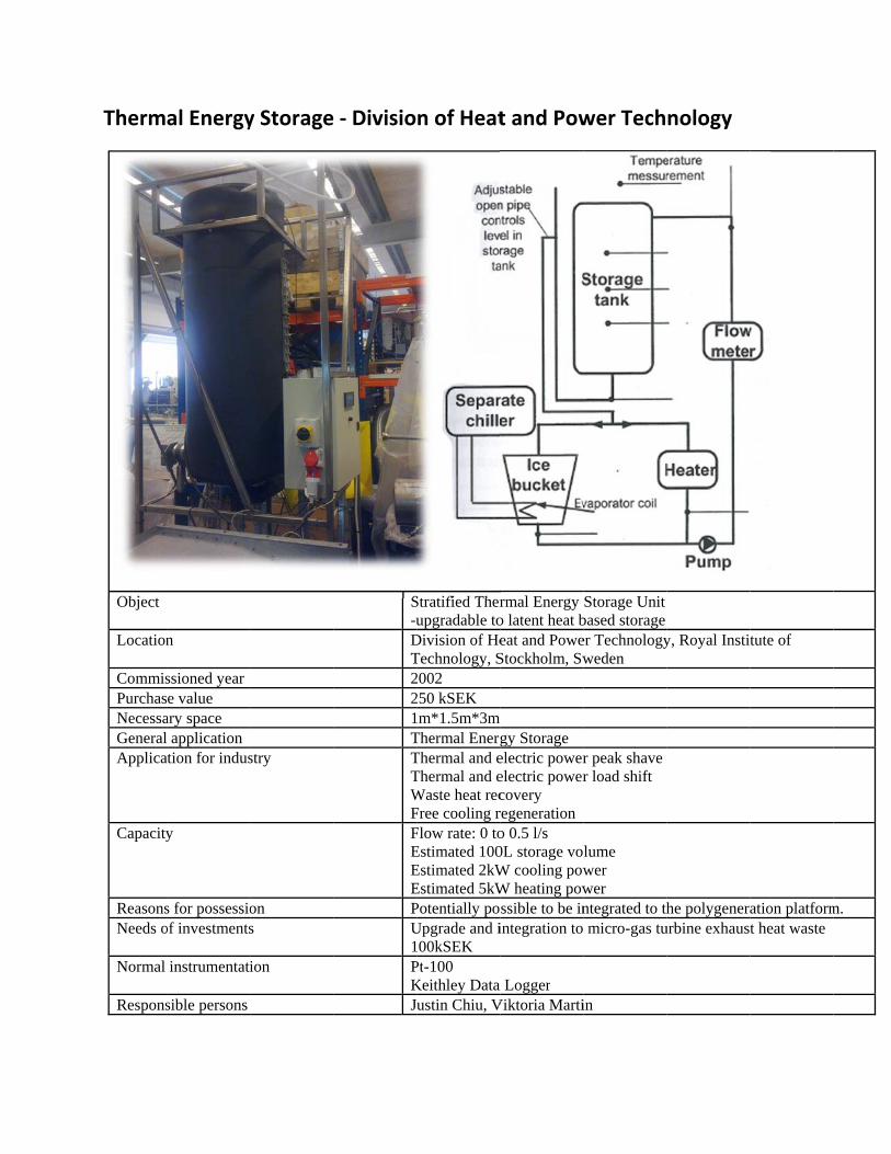
‐ Divisio
S-uDT221TTTWFFEEEPU1PKJ
n of Heat
Stratified Therupgradable to
Division of HeTechnology, S2002 250 kSEK
m*1.5m*3mThermal EnergThermal and eThermal and eWaste heat recFree cooling rFlow rate: 0 toEstimated 100Estimated 2kWEstimated 5kWPotentially poUpgrade and i
00kSEK Pt-100 Keithley Data ustin Chiu, V
t and Pow
rmal Energy o latent heat beat and PoweStockholm, Sw
m gy Storage electric powerelectric powercovery regenerationo 0.5 l/s 0L storage voW cooling powW heating powssible to be inintegration to
a Logger Viktoria Marti
wer Tech
Storage Unit based storage er Technologyweden
r peak shave r load shift
lume wer wer ntegrated to th micro-gas tu
in
nology
y, Royal Instit
he polygeneraurbine exhaust
tute of
ation platformt heat waste
m.
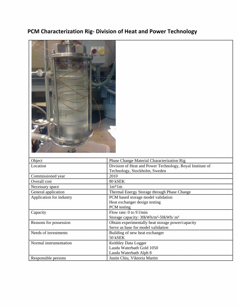
PCM C
Object Location
CommisOverall NecessaGeneralApplica
Capacity
Reasons
Needs o
Normal
Respons
haracteri
n
ssioned year cost
ary space l application ation for indus
y
s for possessio
of investments
instrumentati
sible persons
ization Ri
stry
on
s
ion
ig‐ Divisio
PDT281TPHPFSOSB5KLLJ
on of Hea
Phase ChangeDivision of HeTechnology, S2010 80 kSEK
m*1m Thermal EnergPCM based stHeat exchangePCM testing Flow rate: 0 toStorage capacObtain experimServe as base Building of ne50 kSEK Keithley Data Lauda WaterbLauda Waterbustin Chiu, V
at and Po
e Material Chaeat and PoweStockholm, Sw
gy Storage thorage modeler design test
o 9 l/min ity: 30kWh/mmentally heatfor model va
ew heat excha
a Logger bath Gold 105bath Alph 8 Viktoria Marti
ower Tech
aracterizationer Technologyweden
hrough Phase validation
ting
m³-50kWh/ mt storage pow
alidation anger
50
in
hnology
n Rig y, Royal Instit
Change
m³ wer/capacity
tute of
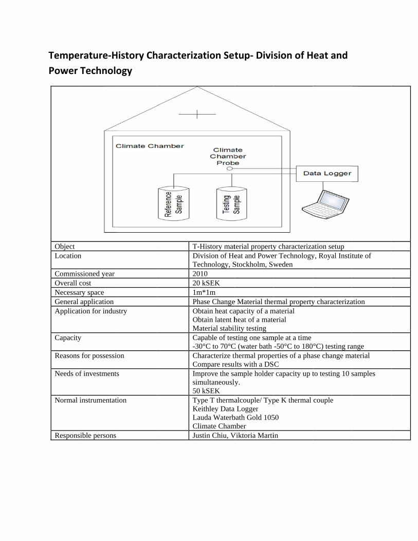
TempePower
Object Location
CommisOverall NecessaGeneralApplica
Capacity
Reasons
Needs o
Normal
Respons
erature‐HTechnolo
n
ssioned year cost
ary space l application ation for indus
y
s for possessio
of investments
instrumentati
sible persons
History Chogy
stry
on
s
ion
haracteriz
TDT221POOMC-3CCIms5TKLCJ
zation Set
T-History matDivision of HeTechnology, S2010 20 kSEK
m*1m Phase ChangeObtain heat caObtain latent hMaterial stabilCapable of tes30°C to 70°C
Characterize thCompare resumprove the saimultaneously
50 kSEK Type T thermaKeithley Data Lauda WaterbClimate Chamustin Chiu, V
tup‐ Divi
terial propertyeat and PoweStockholm, Sw
e Material therapacity of a mheat of a matelity testing sting one sam
C (water bath thermal propeults with a DSample holder y.
alcouple/ Typa Logger bath Gold 105mber Viktoria Marti
sion of H
y characterizaer Technologyweden
rmal propertymaterial erial
mple at a time -50°C to 180
erties of a phaC
r capacity up t
pe K thermal
50
in
eat and
ation setup y, Royal Instit
y characteriza
°C) testing raase change ma
to testing 10 s
couple
tute of
ation
ange aterial
samples
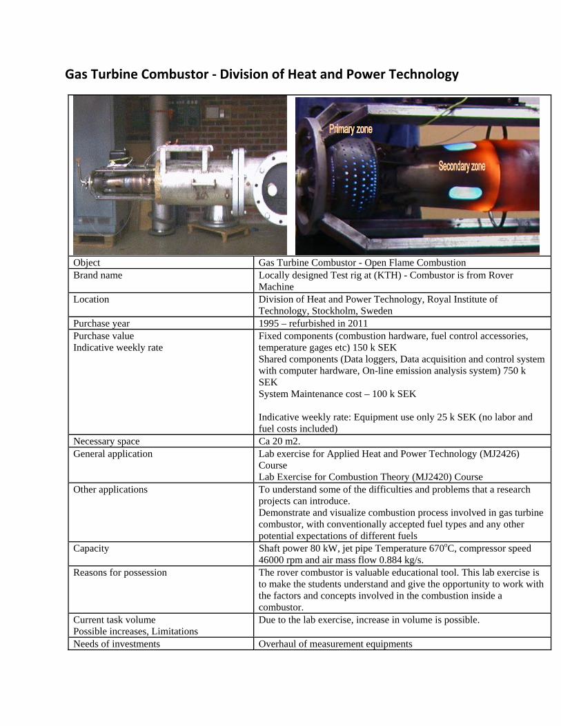
Gas Turbine Combustor ‐ Division of Heat and Power Technology
Object Gas Turbine Combustor - Open Flame Combustion Brand name Locally designed Test rig at (KTH) - Combustor is from Rover
Machine Location Division of Heat and Power Technology, Royal Institute of
Technology, Stockholm, Sweden Purchase year 1995 – refurbished in 2011 Purchase value Indicative weekly rate
Fixed components (combustion hardware, fuel control accessories, temperature gages etc) 150 k SEK Shared components (Data loggers, Data acquisition and control system with computer hardware, On-line emission analysis system) 750 k SEK System Maintenance cost – 100 k SEK Indicative weekly rate: Equipment use only 25 k SEK (no labor and fuel costs included)
Necessary space Ca 20 m2. General application Lab exercise for Applied Heat and Power Technology (MJ2426)
Course Lab Exercise for Combustion Theory (MJ2420) Course
Other applications To understand some of the difficulties and problems that a research projects can introduce. Demonstrate and visualize combustion process involved in gas turbine combustor, with conventionally accepted fuel types and any other potential expectations of different fuels
Capacity Shaft power 80 kW, jet pipe Temperature 670oC, compressor speed 46000 rpm and air mass flow 0.884 kg/s.
Reasons for possession The rover combustor is valuable educational tool. This lab exercise is to make the students understand and give the opportunity to work with the factors and concepts involved in the combustion inside a combustor.
Current task volume Possible increases, Limitations
Due to the lab exercise, increase in volume is possible.
Needs of investments Overhaul of measurement equipments
Normal instrumentation LabView as data acquisition system, online gas analyzers for NOx, UHC, CO, O2, H2, CO2: Air flow measurement: Pitot tube, Pressure transducer: Temperature :Thermocouples N type Fuel Flow measurements: Brooks mass flow controller Keithley 2701 data logger.
Loading Availability
Approximately 3-4 hrs lab exercise During April/May of the year approximately for 10 occasions (ten student groups), will run the equipment in MJ2426 course During October/November of the year approximately for 5 to 6 occasions (5 to 6 student groups), will run the equipment in MJ2420 course
Responsible persons Jeevan Jayasuriya (KTH), Ershad Khan (KTH) , Leif Pettersson (KTH) --------------Updated the document in March 2011
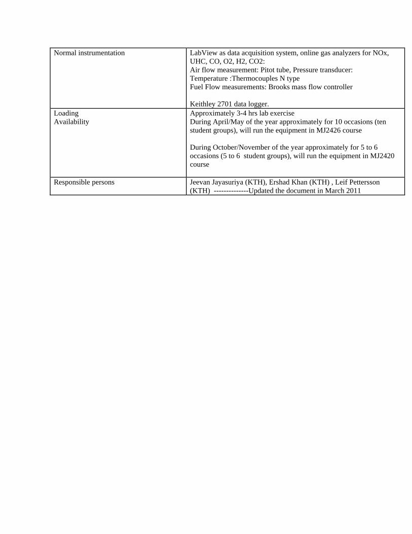
4 bar Air Supply Compressor - Division of Heat and Power Technology
Operator’s panel
Compressor unit
Object 4 bar Compressor Brand name Atlas Copco
ZA4 Location Division of Heat and Power Technology, Royal Institute of
Technology, Stockholm, Sweden Purchase year 1986 Purchase value Indicative weekly rate
500k€ (1986)
Necessary space 20m2 General application Main air supply compressor for 4 bar wind tunnel system,
oil-free compression system, screw compressor principle Other application Air compression in general Capacity 4.5 bara max pressure, 4.75kg/s max mass flow
Air cooler downstream of compressor 20C-80C (district cooling) Cyclone droplet separator installed Electrical drive 1120kW
Reasons for possession
Supplying wind tunnel system with compressed air
Current task volume Possible increases, Limitations
Used continuously
Needs of investments - Normal instrumentation Operator’s panel on compressor side Loading Availability
Loading dependent on wind tunnel use Estimated usage costs: 70Euro/h
Responsible persons Stellan Hedberg (KTH), Damian Vogt (KTH), Jens Fridh (KTH)
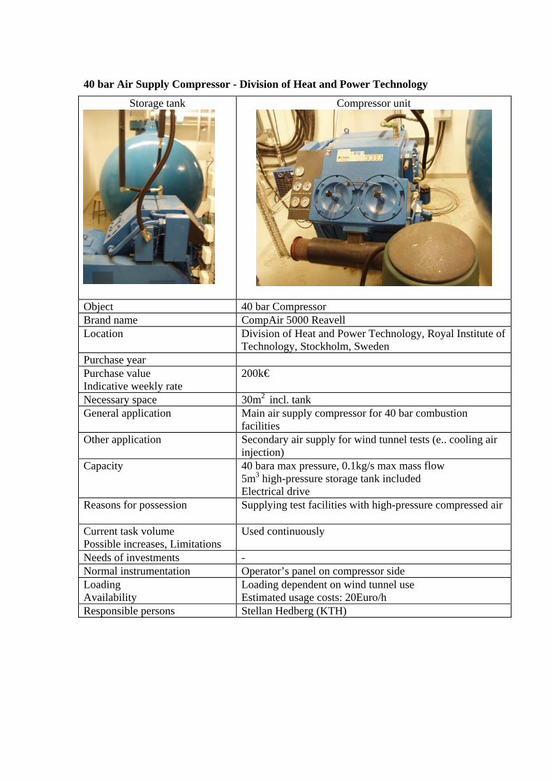
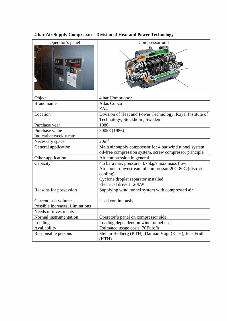
40 bar Air Supply Compressor - Division of Heat and Power Technology
Storage tank
Compressor unit
Object 40 bar Compressor Brand name CompAir 5000 Reavell Location Division of Heat and Power Technology, Royal Institute of
Technology, Stockholm, Sweden Purchase year Purchase value Indicative weekly rate
200k€
Necessary space 30m2 incl. tank General application Main air supply compressor for 40 bar combustion
facilities Other application Secondary air supply for wind tunnel tests (e.. cooling air
injection) Capacity 40 bara max pressure, 0.1kg/s max mass flow
5m3 high-pressure storage tank included Electrical drive
Reasons for possession
Supplying test facilities with high-pressure compressed air
Current task volume Possible increases, Limitations
Used continuously
Needs of investments - Normal instrumentation Operator’s panel on compressor side Loading Availability
Loading dependent on wind tunnel use Estimated usage costs: 20Euro/h
Responsible persons Stellan Hedberg (KTH)