removal and replacement of cast- in-place post- …
TRANSCRIPT

NDOT Research Report
Report No: RDT01-032
REMOVAL and
REPLACEMENT of CAST-IN-PLACE POST-
TENSIONED BOX-GIRDER BRIDGE
December 2001
Prepared by Research Division Nevada Department of Transportation
1263 South Stewart Street Carson City, Nevada 89712

TECHNICAL REPORT DOCUMENTATION PAGE
TECHNICAL REPORT DOCUMENTATION PAGE 1. Report No.RDT 01-032
2. Government Accession No.
3. Recipient=s Catalog No.
4. Title and Subtitle
Removal and Replacement of Cast-in-Place,Post-Tensioned, Box-Girder Bridge
5. Report Date
December 2001
6. Performing Organization Code
7. Author(s)
Frank Reppi, David H. Sanders
8. Performing Organization Report No.
CCEER-01-07
9. Performing Organization Name and Address
Department of Civil Engineering/258University of Nevada, RenoReno, Nevada 89557
10. Work Unit No.
11. Contract or Grant No.
P443-99-803 12. Sponsoring Agency Name and Address
Nevada Department of Transportation 1263 S. Stewart StreetCarson City, NV 89712
13. Type or Report and Period Covered6-7-99 to 6-30-2001
14. Sponsoring Agency Code
15. Supplementary Notes
16. Abstract
This report describes the analytical investigation of the removal and replacement of cast-in-place, post-tensioned, box-girder bridge decks. In order to extend the life of the overall bridge, the deck typically must be replaced. This is problematic in a post-tensioned bridge where the deck is part of the structural system that resists the prestress force. This analytical investigation examines the impact of deck removal and replacement. As bridges deteriorate due to environmental effects, this deterioration is more severe in the decks. Four specific bridges were chosen for analysis. These bridges were two simple span bridges (non-skewed and skewed), a two-span continuous bridge, and a three-span continuous bridge. The investigation was performed on bridges that might be considered for deck replacement in the future. A 3D finite element analysis was performed on all bridges and compared with a 2D analysis. Processes and recommendations for deck removal were given for simple and continuous span bridges. The impact in the amount of skew was also investigated in this topic. Recommendations were also given for traffic analysis and future design considerations for simple and continuous span bridges. It was found that deck removal and replacement must be considered on a case-by-case basis. If the bridge is a simple span bridge, then additional prestressing can be used to support the bridge while the deck is being replaced. The additional prestressing tendons placed on the bottom of the bridge were found to be ineffective at reducing the stress levels for the continuous structures. If the bridge is a continuous span bridge, then a 2D analysis must be performed to evaluate if shoring is necessary. Additional prestressing keeps the concrete stresses within allowable levels. 17. Key Words
Bridges, Deck, Post-Tensioned, Replacement
18. Distribution StatementUnrestricted. This document is available through the National Technical Information Service, Springfield, VA 21161
19. Security Classif. (of this report)
Unclassified20. Security Classif. (of this page)
Unclassified21. No. Of Pages
20622. Price
file:///K|/Research%20Program/Completed%20Projects/...20Tensioned%20Bridge%20Deck%2044399/TechSummary.htm (1 of 2)10/9/2006 1:48:11 PM

TECHNICAL REPORT DOCUMENTATION PAGE
file:///K|/Research%20Program/Completed%20Projects/...20Tensioned%20Bridge%20Deck%2044399/TechSummary.htm (2 of 2)10/9/2006 1:48:11 PM

Removal and Replacement of Cast-in-Place, Post-Tensioned, Box-Girder Bridge
Report No. CCEER 01-07
Frank Reppi David H. Sanders
A Report for the Nevada Department of Transportation
Carson City, Nevada
December 2001
Center for Earthquake Engineering Research Department of Civil Engineering/258 University of Nevada Reno, Nevada 89557

i
Abstract
This report describes the analytical investigation of the removal and replacement
of cast-in-place, post-tensioned, box-girder bridge decks. In order to extend the life of
the overall bridge, the deck typically must be replaced. This is problematic in a post-
tensioned bridge where the deck is part of the structural system that resists the prestress
force. This analytical investigation examines the impact of deck removal and
replacement.
As bridges deteriorate due to environmental effects, this deterioration is more
severe in the decks. Four specific bridges were chosen for analysis. These bridges were
two simple span bridges (non-skewed and skewed), a two-span continuous bridge, and a
three-span continuous bridge. The investigation was performed on bridges that might be
considered for deck replacement in the future.
A 3D finite element analysis was performed on all bridges and compared with a
2D analysis. Processes and recommendations for deck removal were given for simple
and continuous span bridges. The impact in the amount of skew was also investigated in
this topic. Recommendations were also given for traffic analysis and future design
considerations for simple and continuous span bridges.
It was found that deck removal and replacement must be considered on a case-by-
case basis. If the bridge is a simple span bridge, then additional prestressing can be used
to support the bridge while the deck is being replaced. The additional prestressing
tendons placed on the bottom of the bridge were found to be ineffective at reducing the
stress levels for the continuous structures. If the bridge is a continuous span bridge, then

ii
a 2D analysis must be performed to evaluate if shoring is necessary. Additional
prestressing keeps the concrete stresses within allowable levels.

iii
Table of Contents Abstract ................................................................................................................................ i Table of Contents............................................................................................................... iii List of Tables .......................................................................................................................v List of Figures ……………………………………………………………………………vi Chapter 1 Introduction ...................................................................................................1 1.1 Background ...................................................................................................1 1.2 Objectives......................................................................................................3 1.3 Report Layout................................................................................................3 Chapter 2 Bridge Selection and Preliminary Analysis...................................................4 2.1 General Comments ........................................................................................4 2.2 Western DOT Survey ....................................................................................4 2.3 Selection of Bridges ......................................................................................4 2.4 Specifications of Four Bridges ......................................................................6 2.5 Analysis Methods ..........................................................................................7 Tables Chapter 2..........................................................................................10 Figures Chapter 2 ........................................................................................16 Chapter 3 Simple Span Bridges ...................................................................................31 3.1 General comments .......................................................................................31 3.2 Goals for Removing and Replacing ............................................................32 3.3 Comparing 2D Analysis with the 3D Analysis ...........................................33 3.4 Problem with Full Replacement of Deck ....................................................34 3.5 Finding the Amount of Deck Removal and Additional Prestressing ..........35 3.6 Predicting the Amount of Additional Prestress Needed..............................39 3.7 Summary for Bridge G1697S......................................................................42 3.8 Summary for Bridge I1301E .......................................................................43 Tables Chapter 3..........................................................................................45 Figures Chapter 3 ........................................................................................55 Chapter 4 Continuous Span Bridges and Construction Considerations.......................59 4.1 General Comments ......................................................................................59 4.2 Two-Span Bridges (Bridge I871E)..............................................................59 4.3 Three-Span Bridges (Bridge I873) ..............................................................62 4.4 Conclusions for Continuous Span Bridges..................................................64 4.5 Traffic Analysis of Construction Site..........................................................64 4.6 Possible Design Considerations of Bridges.................................................65 Tables Chapter 4..........................................................................................66 Chapter 5 Summary and Conclusions..........................................................................73 5.1 Summary .....................................................................................................73 5.2 Conclusions .................................................................................................74 References..........................................................................................................................75

iv
Appendix A: Survey of Western State DOTs ....................................................................76 Appendix B: Sample Calculations .....................................................................................80 Bridge G1697S ........................................................................................................81 Bridge I1301E .........................................................................................................84 Appendix C: Figures Related to Chapter 3 ........................................................................87 Appendix D: Figures Related to Chapter 4......................................................................156

v
List of Tables
Table 2.1: Post-Tensioned, Box-Girder Bridges in Northern and Southern Nevada ..............................................................................10 Table 3.1a: Comparison of 3D and 2D Analyses of Bridge G1697s and I1301E.....................................................................45 Table 3.1b: Comparison of 3D and 2D Analyses of Bridge G1697s and I1301E.....................................................................46 Table 3.2: Bridge G1697s and I1301E No Deck Properties With Full Additional Dead Load ............................................................47 Table 3.3: Variable Amounts of Deck Removal Using Bridge G1697S .................48 Table 3.4a: Variable Amounts of Additional Prestress Using Bridge G1697S.........49 Table 3.4b: Variable Amounts of Additional Prestress Using Bridge G1697S.........50 Table 3.5: Variable Amounts of Anchorage Distance Using Bridge G1697S.........51 Table 3.6: Summary Results for Bridge G1697S.....................................................52 Table 3.7: Summary Results for Bridge I1301E......................................................53 Table 3.8: Comparison of Final Stress Values Skewed and Non Skewed Bridges...............................................................................54 Table 4.1: Comparison of 3D and 2D Analyses of Bridge I871E ...........................66 Table 4.2a: Summary Results for Bridge I871E Span 1............................................67 Table 4.2b: Summary Results for Bridge I871E Span 2............................................68 Table 4.3: Comparison of 3D and 2D Analyses of Bridge I873..............................69 Table 4.4a: Summary Results for Bridge I873 Span 1 ..............................................70 Table 4.4b: Summary Results for Bridge I873 Span 2 ..............................................71 Table 4.4c: Summary Results for Bridge I873 Span 3 ..............................................72

vi
List of Figures Figure 2.1: Distribution of Simple Span Bridge Lengths Counties 2 and 3..............16 Figure 2.2: Distribution of Simple Span Bridge Lengths County 1 ..........................16 Figure 2.3: Distribution of Simple and Continuous Span Bridge Widths Counties 2 and 3 .........................................................................17 Figure 2.4: Distribution of Simple and Continuous Year of Construction Counties 2 and 3................................................................17 Figure 2.5: Distribution of Degree of Skew Counties 2 and 3 ..................................18 Figure 2.6: Distribution of Simple and Continuous Degree of Skew County 1....................................................................................18 Figure 2.7: Distribution of Continuous Span Bridges Counties 2 and 3 ...................19 Figure 2.8: Distribution of Continuous Span Bridge Lengths Counties 2 and 3......................................................................................19 Figure 2.9: Distribution of Continuous Span Bridge Lengths County 1...................20 Figure 2.10: Bridge G1697S Typical Section and Prestressing Diagram ...................21 Figure 2.11: Bridge I1301E Typical Section and Prestressing Diagram.....................22 Figure 2.12: Bridge I871E Typical Section and Prestressing Diagram.......................23 Figure 2.13: Bridge I873 Typical Section and Prestressing Diagram.........................24 Figure 2.14: Elevation View Bridge G1697S..............................................................25 Figure 2.15: Bridge G1697S Shown Without Bottom Sofit and Top Deck................25 Figure 2.16: Elevation View Bridge I1301E...............................................................26 Figure 2.17: Bridge I1301E Shown Without Bottom Sofit and Top Deck .................26 Figure 2.18: Elevation View Bridge I871E.................................................................27 Figure 2.19: Bridge I871E Shown Without Bottom Sofit and Top Deck ...................27 Figure 2.20: Elevation View Bridge I873 ...................................................................28 Figure 2.21: Bridge I873 Shown Without Bottom Sofit and Top Deck......................28 Figure 2.22: Bridge with No Deck Properties. Typically used for Stage 1 and Stage 2 in 3D Finite Element Analysis ...............................29 Figure 2.23: Bridge With No Deck Properties and an Additional Dead Load Applied at Each Girder. Typically used for Stage 3 in Finite Element Analysis.........................................................29 Figure 2.24: Bridge With Full Deck Properties. Typically Superimposed with Figure 2.23 to Achieve Stage 4 in 3D Finite Element Analysis ....................................................................30 Figure 3.1: Concept of Deck Removal ......................................................................55 Figure 3.2: Section View of Additional Anchor and Tendon ...................................55 Figure 3.3: Stress Ratios for Variable Amounts of Deck Removal ..........................56 Figure 3.4: Stress Ratios for Variable Amounts of Prestress ....................................56 Figure 3.5: Stress Ratios for Variable Amounts of Anchor Distances......................57 Figure 3.6: Reinforcing Steel in Additional Anchor .................................................58 Figure C.1: Bridge G1697S, Full Deck, Top Fiber....................................................88 Figure C.2: Bridge G1697S, Full Deck, Bottom Fiber ..............................................89 Figure C.3: Bridge I1301E, Full Deck, Top Fiber .....................................................90 Figure C.4: Bridge I1301E, Full Deck, Bottom Fiber................................................91 Figure C.5: Bridge G1697S, No Deck, Top Fiber .....................................................92 Figure C.6: Bridge G1697S, No Deck, Bottom Fiber................................................93 Figure C.7: Bridge I1301E, No Deck, Top Fiber.......................................................94

vii
Figure C.8: Bridge I1301E, No Deck, Bottom Fiber .................................................95 Figure C.9: Bridge G1697S, No Deck, DL+PS+ADL, Top Fiber.............................96 Figure C.10: Bridge G1697S, No Deck, DL+PS+ADL, Bottom Fiber .......................97 Figure C.11: Bridge I1301E, No Deck, DL+PS+ADL, Top Fiber ..............................98 Figure C.12: Bridge I1301E, No Deck, DL+PS+ADL, Bottom Fiber.........................99 Figure C.13: Bridge G1697S, 100% Deck Removal, Top Fiber ...............................100 Figure C.14: Bridge G1697S, 100% Deck Removal, Bottom Fiber..........................101 Figure C.15: Bridge G1697S, 90% Deck Removal, Top Fiber .................................102 Figure C.16: Bridge G1697S, 90% Deck Removal, Bottom Fiber............................103 Figure C.17: Bridge G1697S, 80% Deck Removal, Top Fiber .................................104 Figure C.18: Bridge G1697S, 80% Deck Removal, Bottom Fiber............................105 Figure C.19: Bridge G1697S, 70% Deck Removal, Top Fiber .................................106 Figure C.20: Bridge G1697S, 70% Deck Removal, Bottom Fiber............................107 Figure C.21: Bridge G1697S, 60% Deck Removal, Top Fiber .................................108 Figure C.22: Bridge G1697S, 60% Deck Removal, Bottom Fiber............................109 Figure C.23: Bridge G1697S, 50% Deck Removal, Top Fiber .................................110 Figure C.24: Bridge G1697S, 50% Deck Removal, Bottom Fiber............................111 Figure C.25: Bridge G1697S, 600 Kips of Additional Prestress, DL+PS+ADL+APS, Top Fiber.............................................................112 Figure C.26: Bridge G1697S, 600 Kips of Additional Prestress, DL+PS+ADL+APS, Bottom Fiber .......................................................113 Figure C.27: Bridge G1697S, 600 Kips of Additional Prestress, APS, Top Fiber .....................................................................................114 Figure C.28: Bridge G1697S, 600 Kips of Additional Prestress, APS, Bottom Fiber................................................................................115 Figure C.29: Bridge G1697S, 650 Kips of Additional Prestress, DL+PS+ADL+APS, Top Fiber.............................................................116 Figure C.30: Bridge G1697S, 650 Kips of Additional Prestress, DL+PS+ADL+APS, Bottom Fiber .......................................................117 Figure C.31: Bridge G1697S, 650 Kips of Additional Prestress, APS, Top Fiber .....................................................................................118 Figure C.32: Bridge G1697S, 650 Kips of Additional Prestress, APS, Bottom Fiber................................................................................119 Figure C.33: Bridge G1697S, 700 Kips of Additional Prestress, DL+PS+ADL+APS, Top Fiber.............................................................120 Figure C.34: Bridge G1697S, 700 Kips of Additional Prestress, DL+PS+ADL+APS, Bottom Fiber .......................................................121 Figure C.35: Bridge G1697S, 700 Kips of Additional Prestress, APS, Top Fiber .....................................................................................122 Figure C.36: Bridge G1697S, 700 Kips of Additional Prestress, APS, Bottom Fiber................................................................................123 Figure C.37: Bridge G1697S, 750 Kips of Additional Prestress, DL+PS+ADL+APS, Top Fiber.............................................................124 Figure C.38: Bridge G1697S, 750 Kips of Additional Prestress, DL+PS+ADL+APS, Bottom Fiber .......................................................125 Figure C.39: Bridge G1697S, 750 Kips of Additional Prestress, APS, Top Fiber .....................................................................................126 Figure C.40: Bridge G1697S, 750 Kips of Additional Prestress,

viii
APS, Bottom Fiber................................................................................127 Figure C.41: Bridge G1697S, 0 Feet from the Abutment, Top Fiber ........................128 Figure C.42: Bridge G1697S, 0 Feet from the Abutment, Bottom Fiber...................129 Figure C.43: Bridge G1697S, 5.66 Feet from the Abutment, Top Fiber ...................130 Figure C.44: Bridge G1697S, 5.66 Feet from the Abutment, Bottom Fiber..............131 Figure C.45: Bridge G1697S, 11.31 Feet from the Abutment, Top Fiber .................132 Figure C.46: Bridge G1697S, 11.31 Feet from the Abutment, Bottom Fiber............133 Figure C.47: Bridge G1697S, 16.97 Feet from the Abutment, Top Fiber .................134 Figure C.48: Bridge G1697S, 16.97 Feet from the Abutment, Bottom Fiber............135 Figure C.49: Bridge G1697S, 22.63 Feet from the Abutment, Top Fiber .................136 Figure C.50: Bridge G1697S, 22.63 Feet from the Abutment, Bottom Fiber............137 Figure C.51: Bridge G1697S, 28.29 Feet from the Abutment, Top Fiber .................138 Figure C.52: Bridge G1697S, 28.29 Feet from the Abutment, Bottom Fiber............139 Figure C.53: Bridge G1697S, Stage 1, Top Fiber......................................................140 Figure C.54: Bridge G1697S, Stage 1, Bottom Fiber ................................................141 Figure C.55: Bridge G1697S, Stage 2, Top Fiber......................................................142 Figure C.56: Bridge G1697S, Stage 2, Bottom Fiber ................................................143 Figure C.57: Bridge G1697S, Stage 3, Top Fiber......................................................144 Figure C.58: Bridge G1697S, Stage 3, Bottom Fiber ................................................145 Figure C.59: Bridge G1697S, APS, Top Fiber ..........................................................146 Figure C.60: Bridge G1697S, APS, Bottom Fiber.....................................................147 Figure C.61: Bridge I1301E, Stage 1, Top Fiber .......................................................148 Figure C.62: Bridge I1301E, Stage 1, Bottom Fiber..................................................149 Figure C.63: Bridge I1301E, Stage 2, Top Fiber .......................................................150 Figure C.64: Bridge I1301E, Stage 2, Bottom Fiber..................................................151 Figure C.65: Bridge I1301E, Stage 3, Top Fiber .......................................................152 Figure C.66: Bridge I1301E, Stage 3, Bottom Fiber..................................................153 Figure C.67: Bridge I1301E, APS, Top Fiber............................................................154 Figure C.68: Bridge I1301E, APS, Bottom Fiber ......................................................155 Figure D.1: Bridge I871E, Span 1, Stage 1, Top Fiber ............................................157 Figure D.2: Bridge I871E, Span 1, Stage 1, Bottom Fiber.......................................158 Figure D.3: Bridge I871E, Span 2, Stage 1, Top Fiber ............................................159 Figure D.4: Bridge I871E, Span 2, Stage 1, Bottom Fiber.......................................160 Figure D.5: Bridge I871E, Span 1, Stage 2, Top Fiber ............................................161 Figure D.6: Bridge I871E, Span 1, Stage 2, Bottom Fiber.......................................162 Figure D.7: Bridge I871E, Span 2, Stage 2, Top Fiber ............................................163 Figure D.8: Bridge I871E, Span 2, Stage 2, Bottom Fiber.......................................164 Figure D.9: Bridge I871E, Span 1, Stage 3, Top Fiber ............................................165 Figure D.10: Bridge I871E, Span 1, Stage 3, Bottom Fiber.......................................166 Figure D.11: Bridge I871E, Span 2, Stage 3, Top Fiber ............................................167 Figure D.12: Bridge I871E, Span 2, Stage 3, Bottom Fiber.......................................168 Figure D.13: Bridge I871E, Span 1, Stage 3 Alternative, Top Fiber .........................169 Figure D.14: Bridge I871E, Span 1, Stage 3 Alternative, Bottom Fiber....................170 Figure D.15: Bridge I871E, Span 2, Stage 3 Alternative, Top Fiber .........................171 Figure D.16: Bridge I871E, Span 2, Stage 3 Alternative, Bottom Fiber....................172 Figure D.17: Bridge I871E, Span 1, Stage 4, Top Fiber ............................................173 Figure D.18: Bridge I871E, Span 1, Stage 4, Bottom Fiber.......................................174 Figure D.19: Bridge I871E, Span 2, Stage 4, Top Fiber ............................................175

ix
Figure D.20: Bridge I871E, Span 2, Stage 4, Bottom Fiber.......................................176 Figure D.21: Bridge I873, Span 1, Stage 1, Top Fiber...............................................177 Figure D.22: Bridge I873, Span 1, Stage 1, Bottom Fiber .........................................178 Figure D.23: Bridge I873, Span 2, Stage 1, Top Fiber...............................................179 Figure D.24: Bridge I873, Span 2, Stage 1, Bottom Fiber .........................................180 Figure D.25: Bridge I873, Span 3, Stage 1, Top Fiber...............................................181 Figure D.26: Bridge I873, Span 3, Stage 1, Bottom Fiber .........................................182 Figure D.27: Bridge I873, Span 1, Stage 2, Top Fiber...............................................183 Figure D.28: Bridge I873, Span 1, Stage 2, Bottom Fiber .........................................184 Figure D.29: Bridge I873, Span 2, Stage 2, Top Fiber...............................................185 Figure D.30: Bridge I873, Span 2, Stage 2, Bottom Fiber .........................................186 Figure D.31: Bridge I873, Span 3, Stage 2, Top Fiber...............................................187 Figure D.32: Bridge I873, Span 3, Stage 2, Bottom Fiber .........................................188 Figure D.33: Bridge I873, Span 1, Stage 3, Top Fiber...............................................189 Figure D.34: Bridge I873, Span 1, Stage 3, Bottom Fiber .........................................190 Figure D.35: Bridge I873, Span 2, Stage 3, Top Fiber...............................................191 Figure D.36: Bridge I873, Span 2, Stage 3, Bottom Fiber .........................................192 Figure D.37: Bridge I873, Span 3, Stage 3, Top Fiber...............................................193 Figure D.38: Bridge I873, Span 3, Stage 3, Bottom Fiber .........................................194 Figure D.39: Bridge I873, Span 1, Stage 3 Alternative, Top Fiber............................195 Figure D.40: Bridge I873, Span 1, Stage 3 Alternative, Bottom Fiber ......................196 Figure D.41: Bridge I873, Span 2, Stage 3 Alternative, Top Fiber............................197 Figure D.42: Bridge I873, Span 2, Stage 3 Alternative, Bottom Fiber ......................198 Figure D.43: Bridge I873, Span 3, Stage 3 Alternative, Top Fiber............................199 Figure D.44: Bridge I873, Span 3, Stage 3 Alternative, Bottom Fiber ......................200 Figure D.45: Bridge I873, Span 1, Stage 4, Top Fiber...............................................201 Figure D.46: Bridge I873, Span 1, Stage 4, Bottom Fiber .........................................202 Figure D.47: Bridge I873, Span 2, Stage 4, Top Fiber...............................................203 Figure D.48: Bridge I873, Span 2, Stage 4, Bottom Fiber .........................................204 Figure D.49: Bridge I873, Span 3, Stage 4, Top Fiber...............................................205 Figure D.50: Bridge I873, Span 3, Stage 4, Bottom Fiber .........................................206

1
Chapter 1
Introduction
1.1 Background
One of the most popular bridges in the western states is the cast-in-place, post-
tensioned, box-girder bridge system, which accounts for approximately 70 percent of the
concrete bridges in the western states, mainly California, Nevada, and Arizona. Post-
tensioned bridges are shallower in depth than reinforced concrete bridges while spanning
the same length under the same loading conditions. Generally, the post-tensioned
member depth is about 65 to 80 percent less than a typical reinforced concrete member;
therefore, the post-tensioned member requires less concrete and about 20 to 35 percent of
the amount of steel reinforcement.
Prestressing systems result in some added costs to the bridge. The formwork is
more complex, since prestressed sections are normally composed of flanged sections with
thin webs. There are also costs of prestressing the bridge, and the additional costs of
hardware for construction. The initial costs of reinforced concrete bridges and
prestressed bridges are usually very similar. The economic savings of a prestressed
bridge is noticed in the long-term savings. Less maintenance is required on post-
tensioned bridges, and a longer working life is achieved due to compression of the deck.
Also, lighter foundations are achieved from a relatively lighter superstructure.
In western states, specifically north-western states, salt is extensively used to keep
the roads clear during the winter. Deck deterioration is accelerated and while bridges are
designed to last 50 to 75 years, bridges will often require at least one deck replacement
during its design life.

2
During the construction of cast-in-place, post-tensioned, box-girder bridges the
deck or top flange of the structure becomes an integral part of the bridge system. The
deck of the bridge carries the compression force under positive dead load and live load
moment. During prestressing of the system, the compression forces in the deck/top
flange decrease due to the added tension in the top flange from the post-tensioning. The
deck is used and needed to resist the post-tensioning force and the dead load.
This is much different than a pre-tensioned bridge, where the deck is assumed to
be an additional dead load on the pre-tensioned girders. The top flange of the bridge does
not receive any initial critical stresses and acts like a composite section, only under live
load. Therefore, if the deck is removed, the system returns to the configuration it had in
the prestress yard.
If the deck or top flange is removed after prestressing in a post-tensioned bridge,
the compression block must change to account for the new cross sectional properties of
the bridge. In turn, the moment of inertia, in the strong axis, decreases, as well as the
eccentricity of the prestressing tendons. The change of the eccentricity of the
prestressing tendon results in a change of the impact of the post-tensioning. When the
new deck is added, the new concrete acts as additional dead load, and initially has no
stiffness or strength. This is a significant load for the bridge to carry, especially since the
top flange is gone and the eccentricity of the prestress has been altered.
1.2 Objectives
The objective of this project was to develop an economic way to remove and
replace the existing deck in a post-tensioned system and, if necessary, determine how the
design of new structures needs to be altered to facilitate future deck removal. The

3
economic cost of removing and replacing the deck should be less than replacing the full
structure of the bridge. This objective will be accomplished by conducting computer
analyses on representative bridges. These analyses will take the bridges through the
process of deck removal and replacement.
1.4 Report Layout
The following chapters will describe the process that was used to remove and
replace the bridge decks from start to finish. The first step was to select potential bridges
for the analyses. The narrowing of the bridges to four main types is described in Chapter
2. Chapter 2 will describe and compare 2D analysis and 3D analysis results. The results
of the western states survey concerning deck replacement are also described. Chapter 3
will describe the theory and analysis used to remove and replace bridge decks in non-
skewed and skewed simple span bridges. Chapter 3 will also provide two examples of
bridges for which the decks have been removed. Chapter 4 will describe the deck
removal and replacement of continuous span bridges, both 2-span and 3-span bridges.
Chapter 5 will discuss construction and traffic implications as well as any possible design
recommendations for future bridge construction. At the end of the report will be a
summary of the results and their conclusions.

4
Chapter 2
Bridge Selection and Preliminary Analysis
2.1 General Comments
In order to investigate the removal and replacement of cast-in-place, post-
tensioned, box-girder bridge decks, it was decided to select representative bridges for the
analyses. Four bridges were selected that are located in the Northern Nevada area and are
candidates for repair in the future.
2.2 Western DOT Survey
A survey of nine western DOTs was conducted including California, Colorado,
Wyoming, Idaho, Montana, New Mexico, Washington, Texas, and Utah. A copy of the
survey is included in Appendix A. The survey asked if they have ever removed, fully or
partially, any cast-in-place, post-tensioned, box-girder bridge decks. Six states
responded: California, Colorado, Idaho, New Mexico, Texas, and Utah. The response in
all cases was that this had not been done and possibly needed to be looked into (all other
questions in the survey were not answered, therefore no data was provided by the state
DOTs that were surveyed).
2.3 Selection of Bridges
To establish four prototype bridges to research and analyze, a list of bridges was
compiled that are located throughout northern and southern Nevada, shown in Table 2.1.
Even though southern bridges do not have the same deck deterioration affects that the
northern bridges have, southern bridges were used to find a more accurate representation

5
for continuous span bridges. The four prototype bridges selected were a non-skewed
simple-span bridge, a skewed simple-span bridge, a two-span continuous bridge, and a
three-span continuous bridge. These four specific bridges were chosen because they
represent the majority of post-tensioned bridges in Nevada. They are the most probable
bridges that would require deck replacement in the future. Skewed and non-skewed
bridges were selected to determine if skew has an impact. The information was then
analyzed to see the distribution of bridges in different critical categories. Categories of
interest were: simple or continuous span bridges, angle of skew, number of spans, span
lengths, width of bridges, and year of construction. The results of the statistical
distribution of categories are found in Figures 2.1 to 2.9.
Figures 2.1 and 2.2 show the distribution of bridge lengths in county groups one,
two, and three. County groups two and three are bridges located in Northern Nevada, and
county group one is located in Southern Nevada. Emphasis will be placed on groups two
and three since they are in Northern Nevada. A majority of the simple span bridges, non-
skewed and skewed, lie between 100 and 150 feet. Figure 2.3 shows the distribution of
bridge widths in county groups two and three. The majority of the bridges are
approximately 40 to 60 feet in width. Using these figures, Bridge G1697S was chosen to
analyze for the non-skewed simple span bridge. The bridge has no skew, has a 132 foot
span length, and a deck width of 53 feet. Even though the bridge was built in 1994,
which lies outside the distribution shown in Figure 2.4, Bridge G1697S satisfies all other
criteria for a mean standard bridge.
Figures 2.5 and 2.6 show the amount of skew in county groups one, two, and
three. Using the distribution for span and width, shown in Figures 2.1, 2.2, and 2.3, and
the distribution for skewed bridges shown in Figures 2.5 and 2.6, Bridge I1301E was

6
selected for the skewed, simple span bridge. It has a span length of 180 feet, a width of
45 feet, and a 30 degree skew. Even though this bridge was built in 1996 and lies outside
the normal distribution for year of construction, it is a representative bridge for deck
removal in the future.
Figure 2.7 shows that most of the continuous span bridges are in the two to three
span bridge range. Therefore, to properly analyze continuous span bridges, a two-span
and a three-span bridge were chosen for the project. Bridge I871E was chosen for the
analysis of the two-span continuous bridges. It has span lengths of 145 and 165 feet
respectively, which were chosen from the criteria in Figures 2.8 and 2.9. It has a deck
width of 45.5 feet, a 49 degree skew, and was built in 1977. Bridge I873 was chosen for
the analysis of the three-span continuous bridges. It has span lengths of 60, 160, and 60
feet respectively, a deck width of 39 feet, a 15-degree skew, and was built in 1979.
Referencing Figures 2.4 through 2.9, both bridges lie within all categories for the normal
standard bridge to be analyzed.
2.4 Specifications of Four Bridges Details of the four bridges are given in the following section. The data was
received from the Nevada Department of Transportation (NDOT).
Bridge G1697S Bridge I1301E (See Figure 2.10 for typical section (See Figure 2.11 for typical section and prestressing diagram) and prestressing diagram) Span Length = 132 feet Span Length = 180 feet Width = 53 feet Width = 45 feet Skew = 0 degrees Skew = 30 degrees f’c (@ 28 days) = 4,550 psi f’c (@ 28 days) = 5,275 psi Ec = 3,865 ksi Ec = 4,075 ksi Pj = 12,812 kips Pj = 15,256 kips Losses = 32 ksi Losses = 33 ksi

7
Bridge I871E Bridge I873 (See Figure 2.12 for typical section (See Figure 2.13 for typical section and prestressing diagram) and prestressing diagram) Span Length = 145 feet and 165 feet Span Length = 60 feet, 160 feet, and 60 feet Width = 45.5 feet Width = 39.5 feet Skew = 49 degrees Skew = 15 degree f’c (@ 28 days) = 4,400 psi f’c (@ 28 days) = 4,500 psi Ec = 3,780 ksi Ec = 3,824 ksi Pj = 15,754 kips Pj = 10,151 kips Losses = 32 ksi Losses = 32 ksi
2.5 Analysis Methods
The majority of the bridge analyses performed as part of this project were done
with SAP 2000. SAP 2000 is a static, three dimensional, finite element program. SAP
2000 has many other capabilities, such as dynamic loading and nonlinear analysis. The
static analysis served the purpose of this project.
The main structure of the bridges was modeled using shell elements, which
include: girders, sofit, deck, abutments, piers, and diaphragms. The shell element is a
three or four node shape that combines separate membrane and plate bending behaviors.
SAP 2000 allows three possible choices in formulating the shell elements: pure
membrane behavior, pure plate behavior, or full shell behavior. All shell elements in the
bridges were modeled using the full shell element - all forces and moments can be
supported by the element. Besides selecting the material properties of the shell element,
the thickness formulation must also be selected. For diaphragms, abutments and piers a
thicktype shell element was selected. Thicktype shell elements include the effects of
transverse shear deformation. Girders, sofits, and the deck were modeled using a
thintype shell element, which neglects transverse shearing deformation. Figures 2.14
through 2.21 shows the shell element and tendon layout for all the analyzed bridges.

8
Prestressing tendons in the system were modeled using frame elements. The
frame elements had solid circular section properties, and then, by using the prestressing
option in SAP 2000, a specified tension was added to each individual frame element.
Finally, material properties were assigned to the frame and shell elements. Support
conditions were also assigned. The material properties were chosen from the actual
properties of the bridge.
For the 3D finite element analysis for simple span bridges and continuous span
bridges, references are made in relation to different construction phases in the analysis
process. Each stage represents a critical point in construction ranging from Stage 1,
which is the removal of the deck, to Stage 4, which is the final point in construction (the
bridge is able to be in use).
Stage 1 represents the first critical point in construction when the deck has been
removed. Figure 2.22 shows what this stage would typically look like in the finite
element analysis when the deck has been removed and the interior girders have been
exposed. Stage 2 is when techniques will be used to reduce the impact of deck removal.
Figure 2.23 shows Stage 3, the next stage in construction when the deck has been poured
but is not accounted in the stiffness of the bridge. For Stage 3, an additional dead load
has been added to each girder of the bridge simulating a “wet and soggy” deck. Figure
2.24 shows the typical full deck case in the finite element analysis. The figure is the
outline of the bridge including the deck. In Stage 4, the full deck is analyzed with the
methods used in Stage 2 without dead load and without the original prestress. Stage 4
uses the theory of superposition to achieve final results. These stresses from Stage 4
would then be subtracted from the stresses obtained in Stage 3, modeling the impact of
removing the method used in Stage 2. This final stress state would be the stresses at the

9
final stage in construction. These stages will be used in Chapters 3 and 4 to model deck
removal specifically for simple span bridges and then multiple span bridges respectively.
To verify that the 3D analysis was accurate, some 2D modeling was conducted.
This was done with a program called BDS (Bridge Design System) release 4.2. The 3D /
2D analyses are compared separately in Chapter 3 for simple span bridges, and Chapter 4
for continuous span bridges. The BDS program uses Newton’s numerical integration
with increments set at 1/40 of the span length to produce member properties and fixed
end moments. The stiffness method is used to develop distribution factors. The Hardy-
Cross method of moment distribution is used to solve the simultaneous equations. The
moment distribution analysis technique considers the frame members to be linearly
elastic.

10
Cou
nty
Brid
geFe
atur
eFa
cilit
ySk
ewTy
peN
umbe
rLe
ngth
Wid
thD
eck
Year
Num
ber
Inte
rsec
ted
Car
ried
(Mai
n)Sp
ans
Max
. (.1
m)
O-O
(.1m
)R
atin
gB
uilt
2B1
408
WAL
KER
RIV
ERFA
U 3
400
505
140
240
28
1974
2B1
490
TRU
CKE
E R
IVER
OLD
SR
45
2050
53
213
151
719
762
B150
8H
UM
BOLT
RIV
ERIR
ISH
AM
ERIC
AN R
D35
505
221
398
719
862
B151
9W
ALKE
R R
IVER
MIL
LER
LAN
E30
505
135
110
77
1976
2B1
619
HU
MB
OLT
RIV
ER
DU
NC
AN
RO
AD
1050
51
305
949
1996
2B1
534
TRU
CKE
E R
IVER
FAU
668
9950
53
427
189
719
712
G75
1SP
RR
FR 4
0930
505
221
094
719
622
G12
76FA
U 6
47, T
RU
CKE
E R
, SPR
RFA
U 6
630
505
1468
625
97
1991
2G
1504
FAU
649
SPR
R30
505
317
110
47
1996
2G
1697
NU
PRR
US
395
050
51
402
162
719
812
G16
97S
UPR
RU
S 39
50
505
139
316
27
1981
2H
850E
CR
OSS
RO
ADI 8
024
505
112
813
78
1974
2H
850W
CR
OSS
RO
ADI 8
024
505
112
813
78
1974
2H
1247
FAU
655
I 580
1250
51
360
370
719
802
H12
51FA
U 6
52I 5
8012
505
135
141
67
1977
2H
1553
FAU
651
CR
OSS
RO
AD0
505
153
619
58
1977
2H
2008
OLD
VIR
GIN
IA R
OAD
I 580
5150
51
271
405
819
952
I750
I 80
LOC
KWO
OD
DR
IVE
3050
52
210
946
1962
2I8
52E
FAS
398
I 80
050
51
335
139
619
832
I852
WFA
S 39
8I 8
00
505
133
513
96
1983
2I1
248
FAU
654
I 580
750
51
427
370
619
802
I128
9NFR
426
US
395
650
51
427
134
619
742
I128
9SFR
426
US
395
650
51
427
134
619
742
I130
1EFA
U 6
51I 8
030
505
154
913
77
1977
2I1
301W
FAU
651
I 80
3050
51
549
137
719
772
I130
5U
S 39
5FA
U 6
5025
505
229
329
46
1971
2I1
306
US
395
FAU
667
2050
52
293
154
619
712
I174
9NG
OLD
EN V
ALLE
Y R
OAD
US
395
3350
51
472
137
719
882
I174
9SG
OLD
EN V
ALLE
Y R
OAD
US
395
3050
51
472
137
719
882
I177
0NLE
MM
ON
DR
IVE
US
395
750
51
460
137
719
862
I177
0SLE
MM
ON
DR
IVE
US
395
750
51
460
137
719
862
I195
1ZO
LEZZ
I LAN
EI 5
8020
505
165
544
28
1995
2I2
007
OLD
VIR
GIN
IA R
OAD
I 580
4750
51
311
168
819
952
I200
9O
LD V
IRG
INIA
RO
ADI 5
8052
505
126
894
819
952
B16
TRU
CKE
E R
IVER
FAS
427
060
52
408
157
819
932
G17
48N
UPR
RU
S 39
547
605
325
019
97
1988
2G
1748
SU
PRR
US
395
4060
53
223
174
719
882
I126
1U
S 39
5C
RO
SS R
OAD
960
52
354
947
1968
Tabl
e 2.
1: P
ost-T
ensi
oned
, Box
-Gird
er B
ridge
s in
Nor
ther
n an
d So
uthe
rn N
evad
a

11
Cou
nty
Brid
geFe
atur
eFa
cilit
ySk
ewTy
peN
umbe
rLe
ngth
Wid
thD
eck
Year
Num
ber
Inte
rsec
ted
Car
ried
(Mai
n)Sp
ans
Max
. (.1
m)
O-O
(.1m
)R
atin
gB
uilt
2I1
949
FAS
431
MT.
RO
SE H
WY
I 580
4360
52
585
258
819
952
I195
0SR
430
VIR
GIN
IA S
TREE
TI 5
8020
605
242
743
38
1995
2G
1129
FAU
651
UPP
R99
605
432
082
719
962
I195
2SO
UTH
MEA
DO
WS
PKW
I 580
4160
52
466
369
819
952
B153
3TR
UC
KEE
RIV
ER
FAU
662
060
53
195
226
819
982
G14
74I 8
0SP
RR
9960
53
460
N/A
719
772
I177
2TE
RM
INAL
WAY
I 580
RAM
P0
605
940
290
719
883
B894
EM
AGG
IE C
REE
KI 8
00
505
125
314
07
1976
3B8
94W
MAG
GIE
CR
EEK
I 80
050
51
253
140
719
763
B895
ESU
SIE
CR
EEK
I 80
050
51
253
140
719
763
B895
WSU
SIE
CR
EEK
I 80
050
51
253
140
719
763
B111
9H
UM
BOLT
RIV
ERFA
S 22
90
505
310
411
38
1965
3B1
120
HU
MBO
LT R
IVER
FAS
229
050
53
104
113
819
653
B126
7H
EN
DR
ICK
S C
RE
EK
FAS
225
050
51
287
101
719
683
B165
7H
UM
BO
LT R
IVE
RR
EIN
HA
RT
LAN
E0
505
133
510
77
1988
3B1
842
OW
YHE
E R
IVE
RW
OLD
HO
RS
E C
RO
SS
ING
050
51
119
498
1986
3H
1485
EFA
U 5
48I 8
010
505
138
113
78
1976
3H
1485
WFA
U 5
48I 8
010
505
138
113
77
1976
3H
1512
ESH
OSH
ON
E ST
REE
TI 8
00
505
136
613
97
1977
3H
1512
WSH
OSH
ON
E ST
REE
TI 8
00
505
136
613
98
1977
3I8
91E
CR
OSS
RO
ADI 8
00
505
137
814
06
1976
3I8
91W
CR
OSS
RO
ADI 8
00
505
137
814
06
1976
3I9
00E
FAS
222
I 80
2050
51
415
139
719
763
I900
WFA
S 22
2I 8
020
505
141
513
98
1976
3I9
06E
FAU
535
I 80
050
51
314
139
819
773
I906
WFA
U 5
35I 8
00
505
131
413
78
1977
3I9
20E
FAS
223
I 80
1050
51
479
139
619
773
I920
WFA
S 22
3I 8
010
505
147
913
97
1977
3I9
21E
US
93I 8
00
505
145
413
97
1977
3I9
21W
US
93I 8
00
505
145
413
98
1977
3I9
32E
US
93A
I 80
1150
51
415
137
719
773
I932
WU
S 93
AI 8
014
505
141
513
77
1977
3I1
511E
ALAZ
ON
RO
ADI 8
00
505
131
413
97
1977
315
11W
ALAZ
ON
RO
ADI 8
00
505
131
413
97
1977
3B4
55H
UM
BOLT
RIV
ERSR
789
060
52
229
119
819
923
B152
6H
UM
BO
LT R
IVE
RFA
U 5
4299
605
333
517
46
1979
3G
1414
WAT
ER S
T SP
&UPP
R&H
UM
BLT
RFA
U 5
370
605
435
119
56
1980
3H
869E
US
95I 8
00
605
930
513
97
1977
Tabl
e 2.
1 co
n’t:
Post
-Ten
sion
ed, B
ox-G
irder
Brid
ges i
n N
orth
ern
and
Sout
hern
Nev
ada

12
Tabl
e 2.
1: P
ost-T
ensi
oned
, Box
-Gird
er B
ridge
s in
Nor
ther
n an
d So
uthe
rn N
evad
a
Cou
nty
Brid
geFe
atur
eFa
cilit
ySk
ewTy
peN
umbe
rLe
ngth
Wid
thD
eck
Year
Num
ber
Inte
rsec
ted
Car
ried
(Mai
n)Sp
ans
Max
. (.1
m)
O-O
(.1m
)R
atin
gB
uilt
3H
869W
US
95
I 80
060
59
305
139
719
773
H12
05I 8
0C
RO
SS
RO
AD
060
52
396
106
719
763
I871
ESR
788
I 80
4960
52
509
139
719
773
I871
WSR
788
I 80
4960
52
506
139
819
773
I873
I 80
CR
OS
S R
OA
D15
605
348
812
07
1979
3I8
78I 8
0FA
S 3
0424
605
248
817
36
1976
3I8
79I 8
0FA
S 3
050
605
243
915
47
1976
3I8
82I 8
0FA
S 3
0462
605
248
816
97
1976
3I8
96I 8
0C
OU
NTY
RO
AD0
605
241
812
07
1976
1B1
448
FLAM
ING
O W
AS
HI 5
1564
505
143
944
37
1996
1B1
445
DU
CK
CR
EEK
US
395
5650
51
475
369
819
961
B154
0ED
UC
K C
RE
EKFA
U 5
940
505
133
513
47
1996
1B1
540W
DU
CK
CR
EEK
FAU
594
050
51
335
134
719
961
B180
7R
EE
SE R
IVE
RIR
R M
OH
AW
K C
AN
RD
050
51
140
857
1996
1G
779N
UP
RR
I 15
1550
53
158
131
719
961
G77
9SU
PR
RI 1
515
505
315
818
17
1996
1G
1127
UP
RR
FAU
574
3050
51
209
487
419
961
G14
63U
PR
R, A
CC
ES
S R
D. &
DIT
CH
US
95
1550
51
3299
442
719
961
G14
65U
PR
RU
S 9
50
505
133
836
98
1996
1G
1470
UP
RR
US
95
3550
51
372
369
819
961
G21
49O
GD
EN A
VEN
UE
UP
RR
050
52
122
951
819
951
H12
11U
S 9
5W
AS
HIN
GTO
N A
VE
NU
E0
505
239
612
47
1994
1H
1243
US
95
TOR
RE
Y P
INE
S D
RIV
E0
505
137
520
47
1994
1H
1412
PEC
OS
DR
IVE
I 515
2050
51
491
370
719
941
H14
4128
TH S
TRE
ETI 5
152
505
130
544
27
1996
1H
1442
MO
HA
VE R
OA
DI 5
152
505
147
237
27
1996
1H
1445
WYO
MIN
G A
VE
NU
EI 5
150
505
143
948
08
1996
1H
1451
TWA
IN A
VEN
UE
US
95
1150
51
463
443
619
961
H14
54FA
U 6
11/M
OU
NTA
IN V
ISTA
3US
95
3850
51
533
369
719
961
H14
57VI
KIN
G R
OA
DU
S 9
50
505
141
853
37
1996
1H
1458
GR
EE
NW
AY D
RIV
EU
S 9
518
505
145
736
98
1996
1H
1744
IND
US
TRIA
L R
OA
DFA
U 5
928
505
148
243
47
1996
1H
1836
WAR
M S
PRIN
GS
US
95
2350
51
524
369
819
961
H19
01N
IND
US
TRIA
L R
OA
DI 1
535
505
162
225
98
1996
1H
1901
SIN
DU
STR
IAL
RO
AD
I 15
3550
51
622
265
819
961
H19
41IN
DU
STR
IAL
RO
AD
FAU
594
1150
51
530
384
819
941
H19
71N
RO
BIN
DA
LE R
OA
DI 2
15 B
ELT
WAY
2250
51
527
229
819
941
H19
71S
RO
BIN
DA
LE R
OA
DI 2
15 B
ELT
WAY
2250
51
497
192
919
95

13
Cou
nty
Brid
geFe
atur
eFa
cilit
ySk
ewTy
peN
umbe
rLe
ngth
Wid
thD
eck
Year
Num
ber
Inte
rsec
ted
Car
ried
(Mai
n)Sp
ans
Max
. (.1
m)
O-O
(.1m
)R
atin
gB
uilt
1H
2011
I 15
FAU
590
DES
ERT
INN
3250
53
588
344
819
941
H20
32N
FOO
THIL
LS D
RIV
EU
S 95
050
51
533
131
819
941
H20
32S
FOO
THIL
LS D
RIV
EU
S 95
050
51
533
131
819
941
H20
40N
PAR
ADIS
E R
OAD
I 215
BEL
T W
AY51
505
157
622
97
1994
1H
2040
SPA
RAD
ISE
RO
ADI 2
15 B
ELT
WAY
4750
51
549
229
719
951
I944
FAU
599
US
9524
505
130
531
27
1996
1I9
453
FAU
600
US
9511
505
139
028
07
1996
1I9
56I 1
5FA
U 5
7345
505
239
634
26
1996
1I1
453
FAU
593
US
9515
505
153
036
98
1996
1I1
459
SUN
SET
RO
ADU
S 95
2650
51
564
369
719
961
I146
4LA
KE M
EAD
DR
IVE
US
9533
505
238
736
98
1996
1I1
466
US
95H
AOR
IZO
N D
RIV
E0
505
238
131
18
1996
1I1
469
CO
LLEG
E D
RIV
EU
S 95
050
51
533
369
719
961
I147
1U
S 95
WAG
ON
WH
EEL
DR
IVE
050
52
360
265
819
941
I150
5NU
S 95
US
930
505
145
713
97
1994
1I1
505S
US
95U
S 93
050
51
457
139
719
941
I184
3EH
USI
TE P
ARKW
AYR
AMP
R-1
715
505
132
094
819
961
I184
4WR
AMP
R17
HU
SITE
PAR
KWAY
3550
51
351
125
819
961
I189
9U
S 9
5 O
FF R
AM
PFA
U 5
82 S
OU
THB
OU
ND
6350
51
375
131
819
961
I197
2NW
ARM
SPR
ING
S R
OAD
I 215
3150
51
588
230
719
961
I197
2RPA
RAD
ISE
RO
ADR
AMP
1550
51
524
131
819
961
I197
2SW
ARM
SPR
ING
S R
OAD
I 215
3150
51
585
230
719
961
I198
5NR
AMP
R9
I 15
2450
51
219
222
819
961
I198
5SR
AMP
R9
I 15
2450
51
219
192
819
961
I213
8R
AMP
E-N
I 15
050
51
335
457
819
961
B636
AMAR
GO
SA R
IVER
US
9545
605
230
514
38
1996
1B1
405
LAS
VEG
AS W
ASH
FAS
147
1060
53
488
131
719
961
B180
5R
ED R
OC
K W
ASH
FAS
159
1760
52
305
137
719
961
G20
12H
IGH
LAN
D &
SP
RR
& IN
DU
S.
FAU
590
DE
SE
RT
INN
060
510
594
308
819
961
H12
12U
S 95
VEG
AS D
RIV
E1
605
233
511
77
1994
1H
1214
US
95SM
OKE
RAN
CH
060
52
335
117
719
941
B I1
210
US
95FA
U 5
9532
605
235
131
47
1994
1I1
213
US
95LA
KE M
EAD
BLV
D0
605
233
535
48
1994
1I1
216
US
95C
HEY
NN
E AV
E0
605
233
529
67
1994
1I1
219
US
95
& C
ON
CR
ETE
CH
AN
NE
LS
AR
744
060
52
335
296
819
941
I122
1U
S 9
5A
NN
E R
OAD
RA
MP
3260
52
488
107
819
971
I141
5U
S 95
ANN
E R
OAD
35
605
246
941
18
1996
1I1
456
US
95
FAU
594
/RU
SS
ELL
RD
2960
52
360
311
719
96
Tabl
e 2.
1 co
n’t:
Post
-Ten
sion
ed, B
ox-G
irder
Brid
ges i
n N
orth
ern
and
Sout
hern
Nev
ada

14
Cou
nty
Brid
geFe
atur
eFa
cilit
ySk
ewTy
peN
umbe
rLe
ngth
Wid
thD
eck
Year
Num
ber
Inte
rsec
ted
Car
ried
(Mai
n)Sp
ans
Max
. (.1
m)
O-O
(.1m
)R
atin
gB
uilt
1I1
900
US
95W
AGO
NW
HEE
L FL
YOVE
R0
605
351
811
98
1994
1I1
964N
PEC
OS
RO
ADI 2
150
605
234
419
28
1997
1I1
964S
PEC
OS
RO
ADI 2
150
605
234
419
27
1997
1I1
966N
EAST
ERN
AVE
NU
EBE
LTW
AY (I
215)
060
52
320
192
819
961
I196
6SEA
STER
N A
VEN
UE
BELT
WAY
(I21
5)0
605
232
019
28
1996
1I1
969
BELT
WAY
(I 2
15)
WIN
DM
ILL
LAN
E3
605
227
136
97
1996
1I1
973N
AIR
PO
RT
CO
NN
EC
TOR
RA
MP
SI 2
150
605
145
423
98
1994
1I1
973R
AIR
PO
RT
CO
NN
EC
TOR
RA
MP
I 2
15 R
AM
P0
605
535
194
819
941
I197
3SA
IRP
OR
T C
ON
NE
CTO
R R
AM
PS
I 215
060
51
454
239
819
941
I197
7A
IRP
OR
T C
ON
NE
CTO
RS
UN
SE
T R
OA
D20
605
347
231
47
1994
1I1
980
I 215
FAS
604
060
52
442
369
719
941
I198
3NI 2
15 R
AMP
I 15
060
52
335
192
819
961
I198
3SI 2
15 R
AMP
I 15
060
52
335
192
819
961
I198
4NI 2
15I 1
517
605
248
222
38
1994
1I1
984S
I 215
I 15
1760
52
451
223
819
941
I198
6I 2
15R
AMP
R4
9960
52
384
146
819
951
I198
7R
AM
P R
9R
AM
P R
420
605
141
113
19
1994
1I1
989
I 215
IND
UST
RIA
L R
OAD
1560
52
427
207
819
941
I199
0R
AM
OS
R5
& R
9IN
DU
STR
IAL
RO
AD
2660
52
543
207
819
941
I200
6I 1
5 R
AMP
I 215
RAM
P0
605
336
913
18
1994
1I2
135
RU
SSEL
L R
OAD
PAR
ADIS
E R
OAD
060
51
591
247
819
941
H12
18U
S 9
5 &
CO
NC
CH
AN
NE
LAL
EX
AN
DE
R R
OA
D1
605
233
511
78
N/A
1H
1220
US
95LA
NE
MO
UN
TAIN
RD
060
52
335
117
8N
/A1
H14
46FA
U 5
89I 5
1524
605
337
844
37
N/A
1H
1458
US
95H
ARM
ON
AVE
NU
E1
605
234
125
57
N/A
1H
1460
GIB
SON
RO
ADU
S 95
6460
52
564
369
7N
/A1
H18
04U
S 95
STEP
HAN
IE S
TREE
T10
605
233
815
57
N/A
1H
1697
NPE
BBLE
RO
ADBE
LTW
AY (I
215)
3760
52
335
192
8N
/A1
H16
97S
PEBB
LE R
OAD
BELT
WAY
(I21
5)37
605
233
219
28
N/A
1H
1968
BELT
WAY
(I 2
15)
WIG
WAM
AVE
NU
E15
605
039
925
07
N/A
1H
1974
AIR
PO
RT
CO
NN
EC
TOR
PIL
OT
RO
AD10
605
328
718
97
N/A
1H
1976
AIR
PO
RT
CO
NN
EC
TOR
GR
IER
DR
IVE
1160
53
323
189
7N
/A1
H19
79I 2
15G
ILLE
SPIE
STR
EET
060
52
415
296
8N
/A1
H20
13D
ESER
T IN
NLA
S VE
GAS
BLV
D0
605
215
877
67
N/A
1H
2013
WD
ESER
T IN
ND
AVE
DR
IVE
060
52
158
224
8N
/A1
H20
79N
SPEN
CER
STR
EET
BELT
WAY
(I21
5)35
605
228
719
28
N/A
1H
2079
SSP
ENC
ER S
TREE
TBE
LTW
AY (I
215)
3560
52
283
192
8N
/A1
H21
36N
WR
IGH
T BR
OTH
ERS
LAN
EPA
RAD
ISE
RO
AD99
605
442
711
98
N/A
Tabl
e 2.
1 co
n’t:
Post
-Ten
sion
ed, B
ox-G
irder
Brid
ges i
n N
orth
ern
and
Sout
hern
Nev
ada

15
Cou
nty
Brid
geFe
atur
eFa
cilit
ySk
ewTy
peN
umbe
rLe
ngth
Wid
thD
eck
Year
Num
ber
Inte
rsec
ted
Car
ried
(Mai
n)Sp
ans
Max
. (.1
m)
O-O
(.1m
)R
atin
gB
uilt
1H
2136
SW
RIG
HT
BRO
THER
S LA
NE
PAR
ADIS
E R
OAD
9960
52
457
119
8N
/A1
H23
48D
ESER
T IN
N R
OAD
IN/O
UT
CO
NVE
NTI
ON
060
52
164
243
8N
/A1
H23
49D
ESER
T IN
N R
OAD
IN/O
UT
CO
NVE
NTI
ON
060
52
160
122
8N
/A1
H23
50D
ESER
T IN
N R
OAD
IN/O
UT
CO
NVE
NTI
ON
060
52
160
122
8N
/A1
I806
NFA
U 5
91 S
PRIN
G M
TN. R
OAD
I 15
260
52
366
259
7N
/A1
I806
SFA
U 5
91 S
PRIN
G M
TN. R
OAD
I 15
260
52
366
260
7N
/A1
I120
7U
S 95
VALL
EY V
IEW
ST
660
52
335
247
7N
/A1
I120
8U
S 95
FAU
597
060
52
351
399
7N
/A1
I120
9FA
U 5
96U
S 95
060
53
408
367
6N
/A
Tabl
e 2.
1 co
n’t:
Post
-Ten
sion
ed, B
ox-G
irder
Brid
ges i
n N
orth
ern
and
Sout
hern
Nev
ada

16
0
2
4
6
8
10
12
25 to 50 50 to 75 75 to100
100 to125
125 to150
150 to175
175 to200
200 to225
length (feet)
num
ber
of b
ridge
s
Non SkewSkew
G1697S = 132 ft (non sk ew)I1301E = 180 ft (sk ew)
Figure 2.1: Distribution of Simple Span Bridge Lengths County Groups 2 and 3
0
2
4
6
8
10
12
25 to 50 50 to 75 75 to100
100 to125
125 to150
150 to175
175 to200
200 to225
length (feet)
num
ber o
f brid
ges
Non SkewSkew
Figure 2.2: Distribution of Simple Span Bridge Lengths County Group1

17
0
5
10
15
20
25
30
0 to 20 20 to 40 40 to 60 60 to 80 80 to100
100 to120
120 to140
140 to160
skew (degrees)
num
ber
of b
ridge
s
Non SkewSkew
G1697S = 53 ft. (non skew)I1301E = 45 ft. (skew)I871E = 45.5 ft (skew)I873 = 39 ft. (skew)
Figure 2.3: Distribution of Simple and Continuous Span Bridge Widths County Groups 2 and 3
0
5
10
15
20
25
1960 1965 1970 1975 1980 1985 1990 1995 2000
year
num
ber o
f brid
ges
G1697S = 1994 (simp.)I1301E = 1996 (simp.)I871E = 1977 (con't)I873 = 1979 (con't)
Figure 2.4: Distribution of Simple and Continuous Year of Construction County Groups 2 and 3

18
0123456789
10
1 to10
11 to20
21 to30
31 to40
41 to50
51 to60
61 to70
71 to80
81 to90
91 to100
skew (degrees)
num
ber o
f brid
ges
simplecontinuous
G1697S = 0 deg. (simp.)I1301E = 30 deg. (simp.)I871E = 49 deg. (con't)I873 = 15 deg. (con't)
Figure 2.5: Distribution of Degree of Skew County Groups 2 and 3
02468
101214161820
1 to10
11 to20
21 to30
31 to40
41 to50
51 to60
61 to70
71 to80
81 to90
91 to100
skew (degrees)
num
ber o
f brid
ges
G1697S = 0 deg. (simp.)I1301E = 30 deg. (simp.)I871E = 49 deg. (con't)I873 = 15 deg. (con't)
Figure 2.6: Distribution of Simple and Continuous Degree of Skew County Group 1

19
0
1
2
3
4
5
6
7
8
9
2 3 4 9
number of spans
num
ber
of b
ridge
s
Non SkewSkew
Figure 2.7: Distribution of Continuous Span Bridges County Groups 2 and 3
0
1
2
3
4
5
6
7
8
50 to 75 75 to 100 100 to 125 125 to 150 150 to 175 175 to 200
length (feet)
num
ber o
f brid
ges
Non SkewSkew
I871E = 145 ft, 165 ft (sk ew)I873 = 60 ft, 165 ft, 60 ft (sk ew)
Figure 2.8: Distribution of Continuous Span Bridge Lengths County Groups 2 and 3

20
0
2
4
6
8
10
12
50 to 75 75 to 100 100 to 125 125 to 150 150 to 175 175 to 200
length (feet)
num
ber
of b
ridge
s
Non SkewSkew
I871E = 145 ft, 165 ft(sk ew)I873 = 60 ft, 165 ft, 60 ft (sk ew)
Figure 2.9: Distribution of Continuous Span Bridge Lengths County Group 1

21
Figu
re 2
.10
Brid
ge G
1697
S Ty
pica
l Sec
tion
and
Pres
tress
ing
Dia
gram

22
Figu
re 2
.11
Brid
ge I1
301E
Typ
ical
Sec
tion
and
Pres
tress
ing
Dia
gram

23
Figu
re 2
.12
Brid
ge I8
71E
Typi
cal S
ectio
n an
d Pr
estre
ssin
g D
iagr
am

24
Figu
re 2
.13
Brid
ge I8
73 T
ypic
al S
ectio
n an
d Pr
estre
ssin
g D
iagr
am

25
Figure 2.14: Elevation View Bridge G1697S
Figure 2.15: Bridge G1697S Shown Without Bottom Sofit and Top Deck

26
Figure 2.16: Elevation View Bridge I1301E
Figure 2.17: Bridge I1301E Shown Without Bottom Sofit and Top Deck

27
Figure 2.18: Elevation View Bridge I871E
Figure 2.19: Bridge I871E Shown Without Bottom Sofit and Top Deck

28
Figure 2.20: Elevation View Bridge I873
Figure 2.21: Bridge I873 Shown Without Bottom Sofit and Top Deck

29
Figure 2.22: Bridge with No Deck Properties. Used for Stage 1 and Stage 2 in 3D Finite Element Analysis
Figure 2.23: Bridge with No Deck Properties and an Additional Dead Load Applied at Each Girder. Used for Stage 3 in 3D Finite Element Analysis.

30
Figure 2.24: Bridge with Full Deck Properties. Superimposed with Figure 2.23 to achieve Stage 4 in 3D Finite Element Analysis.

31
Chapter 3
Simple Span Bridges
3.1 General Comments
Two different bridges were used to analyze deck removal for the simple span
bridge decks. The first bridge (G1697S) crosses over the Union Pacific Railroad tracks
on U.S. Route 395. It was built in 1981 with one single span of 132 feet in length, no
skew, and has a width of 53 feet. The second bridge (I1301E) intersects the FAU 651 on
Interstate 80. It was built in 1996 with one single span of 180 feet in length, 30 degrees
of skew, and has a width of 50 feet. Even though both bridges were built later than the
average bridge construction date of 1977, it was felt that these specific bridges
represented a good proportion of bridges in the Northern Nevada region.
The solution of removal and replacement of bridges, for simple span bridges, was
based on basic strength of materials principles, as in Eq 3-1.
ƒ = -P/A + -Pey/I + My/I (Eq 3-1)
ƒ = Stress in the critical section of the bridge. P = Amount of prestress in the system at the critical section. A = Cross-sectional area of concrete of the bridge at the critical section. e = Eccentricity of the bridge tendon at the critical section. y = Distance from the center of gravity to the extreme fiber at the critical section. M = Dead load moment for the bridge system at the critical section. I = Moment of Inertia of the bridge system at the critical section. Eq 3-1 was used in developing a process to remove and replace the bridge deck. It will
be shown in Chapter 3 that the solution for removal and replacement of the decks, for
simple span bridges, is to attach additional prestressing tendons on the bottom sofit of the
bridge to give additional support to the structure during deck replacement. An anchoring
system was designed to attach the additional tendons to the interior girders of the bridge.

32
Anchoring to the girders was the most effective way to get maximum benefit out of the
additional prestressing. This chapter will describe the analysis leading up to the decision
to use post-tensioning. It will show the impact of post-tensioning as well as how to
design the system.
3.2 Goals for Removing and Replacing
The main objective in the removal and replacement of cast-in-place, post-
tensioned, box-girder bridge decks is to keep the economic cost of removing the deck
under the economic cost of tearing down the whole bridge and erecting a full new bridge.
Even though the main goal of the project is in the economic comparison, other
engineering goals and objectives had to be kept in mind as well.
The first main objective was to keep the stress below assigned design values in
the extreme tensile fiber and the extreme compression fiber, as the deck was removed and
replaced. For the extreme compression fiber, a maximum compression stress of 0.70f’c
was used, an increase of about 17% from the code value of 0.60f’c (Ref. AASHTO
5.9.4.2.1) for prestress plus total load. Increase in the permitted stress was done because
the increase in stress would be temporary. AASHTO reduces stresses for long-term
effects by 0.85. The inverse of 0.85 is 1.17. The original design f’c was increased by
10% because the concrete in the bridge is well past its 28-day strength. For the extreme
tensile fiber, a maximum stress of 6√f’c is stated by AASHTO 5.9.4.2.2.
The next objective was to remove as much of the deck as possible. It was hoped
that it would be possible to take all of the deck off at one time. It was felt that this would
help construction time tremendously and reduce costs of replacing the deck.

33
3.3 Comparing the 2D analysis with the 3D analysis
It was decided to do several of the analyses in both 2D (BDS) and 3D (SAP-2000)
to verify performance and the accuracy of both models. Table 3.1a and Table 3.1b show
the comparison between the 3D analysis results with the 2D analysis results for the two
simple span Bridges G1697S and I1301E. The comparison has been done for two
separate cases: (1) the original full deck in place with combination of the bridge’s
structure weight and interior post-tensioning effective, Table 3.1a; and (2) when the deck
has been completely removed, dead load includes the weight of the deck and interior
post-tensioning effective, Table 3.1b. Summaries of the 3D analysis full deck case,
Bridges G1697S and I1301E, are shown in Figures C.1 through C.4. The graphs in the
appendix show different stress levels along the width of the bridge at tenth points along
the span of the bridge. Each graph represents a stress reading at 0.10 times the span
length. The bumps in the graphs along the width of the bridge represent stress readings at
the girder/webs. Stresses are relatively higher at the girders than at points along the deck,
due to the stiffness of the girder. The maximum values in the graphs, either tensile or
compressive, are then summarized in the tables. Summaries of the 3D analysis results for
the no deck case, Bridges G1697S and I1301E, are shown in Figures C.5 through C.8.
To compare the 2D and 3D analyses, an average of the top and bottom node stresses was
performed. Looking at Table 3.1a and Table 3.1b, it is shown that the difference between
the average SAP 2000 3D and the BDS 2D results range from 0.9 to 1.10 of each other,
except at the ends and middle where the diaphragm is located. At these locations, the 3D
analysis picks up localized stresses not seen in the 2D analysis. The maximum SAP 2000
3D and the BDS 2D results have larger discrepancies than the average SAP 2000 3D and
the BDS 2D. One discrepancy is with Bridge I1301E for the no deck property case.
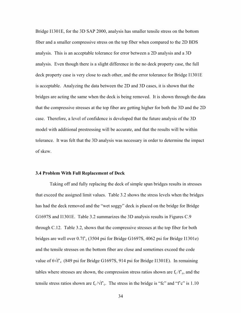
34
Bridge I1301E, for the 3D SAP 2000, analysis has smaller tensile stress on the bottom
fiber and a smaller compressive stress on the top fiber when compared to the 2D BDS
analysis. This is an acceptable tolerance for error between a 2D analysis and a 3D
analysis. Even though there is a slight difference in the no deck property case, the full
deck property case is very close to each other, and the error tolerance for Bridge I1301E
is acceptable. Analyzing the data between the 2D and 3D cases, it is shown that the
bridges are acting the same when the deck is being removed. It is shown through the data
that the compressive stresses at the top fiber are getting higher for both the 3D and the 2D
case. Therefore, a level of confidence is developed that the future analysis of the 3D
model with additional prestressing will be accurate, and that the results will be within
tolerance. It was felt that the 3D analysis was necessary in order to determine the impact
of skew.
3.4 Problem With Full Replacement of Deck
Taking off and fully replacing the deck of simple span bridges results in stresses
that exceed the assigned limit values. Table 3.2 shows the stress levels when the bridges
has had the deck removed and the “wet soggy” deck is placed on the bridge for Bridge
G1697S and I1301E. Table 3.2 summarizes the 3D analysis results in Figures C.9
through C.12. Table 3.2, shows that the compressive stresses at the top fiber for both
bridges are well over 0.7f’c (3504 psi for Bridge G1697S, 4062 psi for Bridge I1301e)
and the tensile stresses on the bottom fiber are close and sometimes exceed the code
value of 6√f’c (849 psi for Bridge G1697S, 914 psi for Bridge I1301E). In remaining
tables where stresses are shown, the compression stress ratios shown are fc /f’c, and the
tensile stress ratios shown are fc /√f’c. The stress in the bridge is “fc” and “f’c” is 1.10
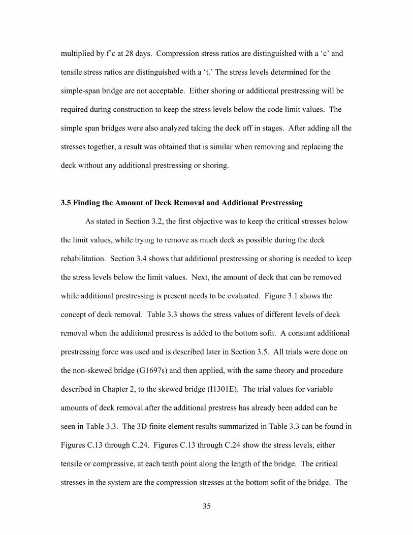
35
multiplied by f’c at 28 days. Compression stress ratios are distinguished with a ‘c’ and
tensile stress ratios are distinguished with a ‘t.’ The stress levels determined for the
simple-span bridge are not acceptable. Either shoring or additional prestressing will be
required during construction to keep the stress levels below the code limit values. The
simple span bridges were also analyzed taking the deck off in stages. After adding all the
stresses together, a result was obtained that is similar when removing and replacing the
deck without any additional prestressing or shoring.
3.5 Finding the Amount of Deck Removal and Additional Prestressing
As stated in Section 3.2, the first objective was to keep the critical stresses below
the limit values, while trying to remove as much deck as possible during the deck
rehabilitation. Section 3.4 shows that additional prestressing or shoring is needed to keep
the stress levels below the limit values. Next, the amount of deck that can be removed
while additional prestressing is present needs to be evaluated. Figure 3.1 shows the
concept of deck removal. Table 3.3 shows the stress values of different levels of deck
removal when the additional prestress is added to the bottom sofit. A constant additional
prestressing force was used and is described later in Section 3.5. All trials were done on
the non-skewed bridge (G1697s) and then applied, with the same theory and procedure
described in Chapter 2, to the skewed bridge (I1301E). The trial values for variable
amounts of deck removal after the additional prestress has already been added can be
seen in Table 3.3. The 3D finite element results summarized in Table 3.3 can be found in
Figures C.13 through C.24. Figures C.13 through C.24 show the stress levels, either
tensile or compressive, at each tenth point along the length of the bridge. The critical
stresses in the system are the compression stresses at the bottom sofit of the bridge. The

36
additional prestressing tendon path can be seen in Figure 3.2, using lan as 9 feet and Dbl
as 2 feet. This type of additional presstrssing tendon path was used to create more uplift
in the bridge. Both of these values will be described later in Chapter 3.
Figure 3.3 shows the pattern of deck removal to stress ratios shown in Table 3.3.
Even at 100% of deck removal, the maximum compression stress is approximately
0.45f’c, which is less than the allowable value of 0.70f’c. As more deck is removed
(going from 50% deck removal to 100% deck removal) the bottom fiber becomes more
compressive as the top fiber becomes more tensile. The analysis, summarized in Table
3.3, was conducted with a constant 900 kips per girder, because it was assumed that
additional prestress values needed would never exceed 900 kips per girder. It was felt
that if the top fiber was kept under the tensile limit values for 900 kips per girder, any
additional prestress less than 900 kips per girder would be adequate in construction and
stresses would be safe. The maximum value of 900 kips per girder was assumed based
on several finite element analyses, and also using engineering judgment. Looking at
Table 3.3, it is shown for 100% deck removal, at 900 kips per girder, stress values are not
close to reaching their maximum values. Therefore, 100% of the full deck can be
removed safely without ever reaching critical stresses.
After determining the amount of deck that can be removed at one time with
prestress, the minimum amount of additional prestress was determined that is needed to
prevent the stresses from going beyond the critical set values range. In the analysis that
produced Table 3.3, a maximum possible amount of additional prestress was assumed
and placed on the sofit of the bridge. This was done to reassure that the top fiber of the
bridge did not go into high tensile stresses during construction. Now it is possible to
determine the minimum amount of prestress needed during construction so that the top

37
fiber would not reach critical compressive stresses. To determine the amount of
additional prestress, different values of additional prestress were applied to the bridge
while removing and replacing all of the deck at once. The additional prestressing tendons
were set at 2 feet below the bottom sofit of the deck. This was set based on possible
clearance situations. The eccentricity of the additional prestressing tendons may be
changed, but the eccentricity value (eadd) in equation 3.2 must also change. This can be
useful when used in overpasses and can also be useful in limiting additional prestressing
values. Critical stresses for variable amounts of additional prestress for full deck removal
and replacement can be referenced in Tables 3.4a and 3.4b. In Tables 3.4a and 3.4b ‘DL’
represents dead load, ‘PS’ represents prestressing force in the bridge, ‘ADL’ represents
additional dead load due to a “wet and soggy” deck, and ‘APS’ represents the additional
prestressing force added to the bottom sofit. The 3D finite element results are given in
Figures C.25 through C.40. The analysis to find the minimum amount of prestress was
done for the final stage in construction (Stage 4), because the critical compressive
stresses in the top fiber are reached when the additional prestress is cut from the system.
After the additional prestress is released from the system, the bridge will be under its own
weight, is when the final stresses will be locked into the system and need to be under
limit values. Therefore, the final stage in construction is found to be the most critical for
compressive stresses. By looking at the final stage in construction in Tables 3.4a and
3.4b, the minimum amount of prestress can be determined while keeping the maximum
compressive stress below 0.70f’c. Figure 3.4 shows the pattern of additional prestress
values to stress ratio that are shown in Tables 3.4a and 3.4b. This shows that the
minimum prestress value is 750 kips. The critical tensile stress of 6√f’c was not a factor
during construction. During the removal and replacement of simple span bridge decks,

38
the system went into tension at the end abutments, which are due to different stress values
along the abutment. 2D analysis does not take into account the stiff end abutments,
which is why there are the end differences between the two. Since the end diaphragm
abutments are fully supported, there is no need to do a 3D analysis to determine the stress
in them as the difference in the end abutment values are of no concern. By referencing
the figures in Appendix A, and looking at the stresses at the abutment sections, the
different stress values along the end abutment can be seen. The analysis shows that the
deck will be in compression under DL+PS. This is very good for durability issues and is
the same as the original design.
3.6 Predicting the Amount of Additional Prestress Needed
Now that an additional prestressing force has been estimated by trial values, a
simpler method needs to be developed. This will be done by formulating an equation that
calculates the amount of additional prestressing force.
The first step in finding an equation that will measure the amount of prestress
needed is to find the section properties at midspan for a full deck system and for a no
deck system (Ac, Ixx, Ytop, Ybot, and e). The next step is to write out the basic method
equation including the additional prestress added to the system for the case when the deck
is completely removed with the additional dead load of a wet deck. This equation is
based on Equation 3-1. The third step is subtracting the additional prestress on the full
composite system. This will model the final stage in construction when the deck has
been completely removed, replaced, and the additional prestressing tendons have been
released. Equation 3-2 is the expanded version of Equation 3-1 to model the final stage
in construction.

39
ƒ = [-Peff/Ac + -PeffebrYtop/Ixx + MfullYtop/Ixx + -Padd/Ac + -PaddeaddYtop/Ixx]no deck –
[-Padd/Ac + -PaddeaddYtop/Ixx]full deck (Eq 3-2)
Peff = Total effective prestress currently in the bridge system. Padd = Total effective additional prestress added to the system. Ac = Area of concrete of the bridge. Ixx = Moment of inertia in the direction of bending. Ytop = Center of gravity to the top fiber of the bridge. ebr = Eccentricity to the prestressing tendons currently in the bridge system. eadd = Eccentricity to the additional prestressing tendons. Mfull = Moment that the dead load of the full deck will generate. no deck = Cross sectional properties at midspan with the deck fully removed. full deck = Cross sectional properties at midspan using the full deck effective. ƒ = The critical compressive stress in the system. Determined to be 0.70f’c The critical stress (ƒ) is set as 0.7 f’c and (Ybot + Dbl) is used for the eadd, where Dbl
denotes the depth of the exterior bearing anchor for the additonal prestressing tendons,
reference Figure 3.2. Since the design value of f’c will exceed its 28-day setting strength,
increasing the 28-day design value by 10% for the critical stress in the system is possible.
Different section properties are used for certain times during the construction process.
Where the subscript full is specified, all full deck section properties are to be used, and
where the subscript no is specified, all no deck section properties are to be used. After all
values are entered, Padd can be solved which is the additional prestress to be added in the
system.
The additional prestressing value calculated is a very good estimate on what final
value is to be added to the system, but there are certain losses that need to be taken into
account. Unlike normal post-tensioned concrete design, long-term losses in the system
do not need to be accounted for, but short-term losses are going to play a factor in the
design. The only short-term losses needed to be taken into account in the design are
anchorage set and elastic shortening, which is estimated to be about 5%. Elastic

40
shortening can be accounted for approximately 3% - 4%, while anchorage setting will be
limited due to the size of the anchor.
The last step is to multiply the final jacking force by an alpha (α) factor for
localized stresses in the system. This was analyzed by using a constant prestressing force
and moving the anchorage of the additional prestressing force to different locations along
the beam. Figure 3.5 shows the pattern of the maximum stress ratios to the distance the
anchorage is from the given support in Table 3.5. The values in Table 3.5 and Figure 3.5
are the maximum stress values measured along the span length. As the anchor gets
farther from the abutment, the maximum compression stresses on the top fiber at midspan
increases, but this is not he controlling stresses. The 3D finite element analysis results
for Table 3.5 can be referenced in Figures C.41 through C.52. The 3D finite element
analysis was run with only dead load of the structure and the additional prestressing
anchorage on the bottom sofit. It was done this way to more accurately measure the
amount of loss due to additional anchorage distance from the abutment.
α = 2 x lan/lspan (Eq 3-3)
α: Percentage of loss due to anchorage distance from the abutment. lan: Length of the anchorage to the end abutment shown in Figure 3.4. lspan: Span length.
There is a large increase in the maximum stresses at the top fiber as the anchorage
is placed farther from the abutment face. While the concrete stresses were only
monitored at limited locations, there are significant increases in the maximum stresses
after the anchorage moves past the 10% point. Therefore, it is suggested that if the
anchorage is placed within 10% of the span length from the abutment face, the localized
stress factor (α) can be neglected. This can be shown in Figure 3.5 when the anchorage
distance is about 17 feet from the abutment. Even though the localized stress factor can

41
be neglected, it is shown in Table 3.6 and 3.7 that the localized stress factor results in a
better correlation between the calculations and the 3D finite element analysis.
After the final additional prestressing value has been multiplied by all losses, the
additional prestressing that shall be distributed between girders in the system is achieved.
3.7 Summary for Bridge G1697S
For Bridge G1697S, an additional jacking prestress force of 585 kips per girder is
needed to keep the bridge under critical stresses during construction. This will be shown
in the calculations for Bridge G1697S in Appendix B. Table 3.6 shows the critical
stresses across the deck of the bridge at different stages in construction using an
additional prestressing force of 585 kips. The 3D finite element analysis results are
shown in Figures C.53 through C.60.
Stage 1 (Dead Load + Prestress) is when the deck has been fully removed from
the bridge, and no additional prestressing force is acting on the system. The only force in
the system is the prestressing force that is currently in the bridge. The critical stresses are
at approximately midspan when the top fiber is in compression, approximately 0.65f’c.
Stage 2 (Dead Load + Prestress + Additional Prestress) is when the additional
jacking force of 585 kips has been placed on the system. By inspection of the stresses,
the bridge cambers up, making the top fiber compression stresses reduce to about 0.17f’c.
Stage 3 (Dead Load + Prestress + Additional Prestress + Additional Dead Load) is
when the additional prestressing force on the system has taken into account short-term
losses and other various losses covered in Section 3.6. Also, at this point in time, the
deck has been fully placed. During this time, the deck carries no stiffness, acts as an
additional load on the bridge, and is just a “soft concrete deck.”

42
The next column, in Table 3.6, shows the stresses caused by the additional
effective prestressing force on the system, with no other type of loading. Stage 4 (Dead
Load + Prestress + Additional Dead Load) is when the deck has hardened and the
additional prestressing force has been released from the bridge. At this point in time, the
critical stresses are at the top fiber, and are just under 0.70f’c, which was the target stress
that was designed for in Equation 3-2.
3.8 Summary for Bridge I1301E
Table 3.7 shows the summary of results from the 3D finite element analysis of
different stages of construction during the removal of the bridge deck. The actual
analysis results can be referenced in Figures C.61 through C.68. The calculations are
shown in Appendix B. A final additional prestressing value of 348 kips per girder was
calculated.
The 30-degree skew of Bridge I1301E made little impact on the design of the
bridge. Referencing Table 3.7 and comparing it to Table 3.6, the stresses do not change
much from the impact of the skewed or non-skewed bridges. Table 3.8 shows the actual
percent difference between the final stress values at the critical final stage in construction.
At Stage 1 of the skewed bridge, the critical stresses are at about 0.51f’c and stay
at about the same level as the non-skewed bridge. The end result, based on the 3D finite
element analysis, of Stage 4 is about 0.68f’c, which is also just under the predicted value
(0.70f’c) using Equation 3.2. This reinforces the limited impact of skew since Equation
3.2 does not include skew.
In conclusion, the impact of skew on bridge decks is not seen in the removal and
replacement of decks in simple-span post tensioned box girder bridge decks. Looking at

43
the analysis results, the critical variables of the problem are length of the bridge, section
properties, and amount of prestress already in the system. From the analysis results,
equation 3-2 was developed in determining the amount of additional prestress needed in
the system to account for the “wet” concrete decking during the pouring of the deck.
Using Equation 3-2, and using basic design principles, the decks in simple span bridges
can safely be removed and replaced during construction while keeping the stresses under
specified critical range. Based on the analysis and data provided, the simple analysis can
be done instead of conducting a 2D or 3D analysis when removing and replacing decks in
simple span bridges. Simple calculations can be performed as provided in Appendix B.

44
Tabl
e 3.
1a: C
ompa
rison
of 3
D a
nd 2
D A
naly
sis o
f Brid
ge G
1697
S an
d I1
301E
Leng
th(ft
)To
p Fi
ber
Bot
tom
Fib
erTo
p Fi
ber
Bot
tom
Fib
erTo
p Fi
ber
Bot
tom
Fib
erTo
p Fi
ber
Bot
tom
Fib
erTo
p Fi
ber
Bot
tom
Fib
er0
-373
-223
-258
-151
-647
-541
0.57
70.
412
0.39
80.
278
13.2
-894
-608
-864
-577
-854
-650
1.04
70.
935
1.01
20.
888
26.4
-102
6-5
81-9
95-5
71-9
36-6
211.
096
0.93
61.
063
0.92
039
.6-1
077
-533
-105
4-5
23-9
75-5
841.
104
0.91
31.
081
0.89
552
.8-1
101
-508
-108
6-4
97-9
96-5
701.
105
0.89
11.
090
0.87
366
-116
2-3
47-7
81-3
06-1
002
-578
1.16
00.
600
0.78
00.
530
79.2
-110
0-5
07-1
086
-498
-996
-570
1.10
40.
889
1.09
00.
873
92.4
-107
2-5
32-1
054
-523
-975
-584
1.09
90.
911
1.08
10.
895
105.
6-1
017
-598
-996
-571
-936
-621
1.08
70.
963
1.06
40.
919
118.
8-8
87-6
60-8
63-5
75-8
54-6
501.
039
1.01
51.
010
0.88
413
2-3
69-2
20-2
18-1
20-6
47-5
410.
570
0.40
70.
337
0.22
2
0-4
32-5
26-2
54-1
70-6
83-5
580.
632
0.94
30.
371
0.30
518
-109
0-6
30-9
38-5
62-1
113
-534
0.97
91.
180
0.84
31.
053
36-1
256
-404
-116
7-3
67-1
330
-393
0.94
51.
029
0.87
70.
933
54-1
389
-285
-131
6-2
56-1
481
-301
0.93
80.
947
0.88
90.
851
72-1
457
-239
-139
4-2
15-1
568
-255
0.92
90.
937
0.88
90.
842
90-1
448
-220
-141
9-2
03-1
594
-254
0.90
80.
865
0.89
00.
801
108
-145
9-2
40-1
394
-215
-156
8-2
550.
931
0.94
10.
889
0.84
212
6-1
394
-283
-131
9-2
54-1
481
-301
0.94
10.
941
0.89
00.
845
144
-126
0-3
91-1
169
-361
-133
0-3
930.
947
0.99
40.
879
0.91
916
2-1
063
-639
-932
-535
-111
3-5
340.
955
1.19
60.
838
1.00
118
0-3
84-5
90-1
49-1
50-6
83-5
580.
563
1.05
70.
218
0.26
9
Avg.
SA
P 20
00 /
BD
S
Full
Sect
ion
Brid
ge I1
301E
Max
. SA
P 20
00 /
BD
SM
ax. S
AP 2
000
(psi
)B
DS
(psi
)B
ridge
G16
97S
Avg.
SAP
200
0 (p
si)

45
Leng
th(ft
)To
p Fi
ber
Bot
tom
Fib
erTo
p Fi
ber
Bot
tom
Fib
erTo
p Fi
ber
Bot
tom
Fib
erTo
p Fi
ber
Bot
tom
Fib
erTo
p Fi
ber
Bot
tom
Fib
er0
252
-117
-39
-56
-238
2-2
6-0
.106
4.49
20.
017
2.15
413
.2-2
804
-435
-276
5-2
65-3
750
-209
0.74
82.
084
0.73
71.
268
26.4
-337
2-5
60-3
316
-442
-366
4-4
260.
920
1.31
60.
905
1.03
839
.6-3
264
-643
-321
7-6
20-3
335
-585
0.97
91.
099
0.96
51.
060
52.8
-321
0-6
94-3
134
-673
-312
9-6
901.
026
1.00
61.
002
0.97
566
-211
7-4
45-5
83-3
79-3
055
-738
0.69
30.
602
0.19
10.
513
79.2
-321
2-6
94-3
134
-672
-312
9-6
901.
026
1.00
61.
002
0.97
592
.4-3
268
-642
-321
7-6
25-3
335
-585
0.98
01.
098
0.96
51.
068
105.
6-3
368
-559
-331
5-4
83-3
664
-426
0.91
91.
313
0.90
51.
134
118.
8-2
806
-432
-276
3-2
51-3
750
-209
0.74
82.
068
0.73
71.
201
132
235
-118
-39
-29
-238
2-2
6-0
.099
4.53
80.
016
1.12
7
025
731
4-9
6-9
3-1
572
-142
-0.1
64-2
.214
0.06
10.
653
18-3
204
326
-255
421
8-2
627
315
1.21
91.
034
0.97
20.
692
36-3
272
361
-287
127
5-2
835
280
1.15
41.
289
1.01
30.
982
54-3
071
227
-299
521
8-2
971
245
1.03
40.
927
1.00
80.
890
72-3
267
215
-306
620
8-3
043
232
1.07
40.
927
1.00
80.
897
90-3
382
181
-308
519
3-3
059
227
1.10
60.
797
1.00
80.
850
108
-328
222
0-3
063
210
-304
323
21.
078
0.94
81.
007
0.90
512
6-3
020
226
-298
821
6-2
971
245
1.01
60.
924
1.00
60.
882
144
-315
429
3-2
854
263
-283
528
01.
112
1.04
51.
007
0.93
916
2-3
111
252
-248
622
3-2
627
315
1.18
40.
800
0.94
60.
708
180
323
673
8020
6-1
572
-142
-0.2
06-4
.742
-0.0
51-1
.449
No
Dec
k Se
ctio
n W
ithou
t Dec
k W
eigh
t
Brid
ge I1
301E
Max
. SA
P 20
00 /
BD
SB
DS
(psi
)B
ridge
G16
97S
Avg.
SA
P 20
00 /
BD
SM
ax. S
AP 2
000
(psi
)Av
g. S
AP 2
000
(psi
)
Tabl
e 3.
1b C
ompa
rison
of 3
D a
nd 2
D A
naly
sis o
f Brid
ge G
1697
S an
d I1
301E

46
LEN
GTH
(ft) 0
255
t11
2t
3.60
5t
1.58
3t
13.2
-342
0c
241
t0.
683
c3.
403
t26
.4-4
837
c44
5t
0.96
6c
6.28
3t
39.6
-520
8c
501
t1.
040
c7.
083
t52
.8-5
392
c50
5t
1.07
7c
7.14
2t
6613
0t
290
t1.
834
t4.
104
t79
.2-5
388
c50
5t
1.07
7c
7.14
2t
92.4
-520
2c
499
t1.
039
c7.
059
t10
5.6
-483
3c
439
t0.
966
c6.
204
t11
8.8
-343
1c
232
t0.
685
c3.
279
t13
223
3t
202
t3.
293
t2.
850
t
LEN
GTH
(ft) 0
266
t47
6t
3.49
2t
6.24
6t
18-3
675
c11
71t
0.63
3c
15.3
76t
36-4
218
c91
3t
0.72
7c
11.9
86t
54-4
213
c87
4t
0.72
6c
11.4
80t
72-4
558
c76
1t
0.78
6c
9.99
7t
90-4
721
c72
9t
0.81
4c
9.57
1t
108
-456
7c
768
t0.
787
c10
.084
t12
6-4
190
c87
1t
0.72
2c
11.4
32t
144
-407
2c
838
t0.
702
c11
.005
t16
2-3
600
c74
9t
0.62
0c
9.83
3t
180
337
t77
6t
4.42
3t
10.1
91t
DL+
PS+A
DL
DL+
PS+A
DL
Brid
ge G
1697
S St
ress
es (p
si)
Brid
ge I1
301E
Str
esse
s (p
si)
DL+
PS+A
DL
TOP
FIB
ERB
OTT
OM
FIB
ERD
L+PS
+AD
LTO
P FI
BER
BO
TTO
M F
IBER
TOP
FIB
ERB
OTT
OM
FIB
ERTO
P FI
BER
BO
TTO
M F
IBER
Tabl
e 3.
2: B
ridge
s G16
97S
and
I130
1E, N
o D
eck
Prop
ertie
s with
Ful
l Add
ition
al D
ead
Load

47
Table 3.3: Variable Amounts of Deck Removal Using Bridge G1697S
a) Stress Values
LENGTH(ft)0 284 t 113 t 1 t 125 t -394 c 131 t
13.2 -987 c -1707 c -1000 c -1702 c 47 t -1771 c26.4 -1022 c -2294 c -1034 c -2282 c -1080 c -2232 c39.6 -936 c -2242 c -952 c -2235 c -1011 c -2202 c52.8 -887 c -2233 c -899 c -2227 c -969 c -2200 c66 -714 c -1571 c -722 c -1566 c -758 c -1545 c
79.2 -900 c -2235 c -915 c -2229 c -974 c -2202 c92.4 -929 c -2250 c -948 c -2242 c -1017 c -2210 c
105.6 -997 c -2333 c -1000 c -2321 c -1063 c -2276 c118.8 -988 c -1778 c -1014 c -1770 c 53 t -1835 c132 302 t 193 t 64 t 310 t 66 t 340 t
b) Stress Ratios
LENGTH(ft)0 4.021 t 1.594 t 0.019 t 1.760 t 0.079 c 1.856 t
13.2 0.197 c 0.341 c 0.200 c 0.340 c 0.664 t 0.354 c26.4 0.204 c 0.458 c 0.207 c 0.456 c 0.216 c 0.446 c39.6 0.187 c 0.448 c 0.190 c 0.446 c 0.202 c 0.440 c52.8 0.177 c 0.446 c 0.180 c 0.445 c 0.194 c 0.440 c66 0.143 c 0.314 c 0.144 c 0.313 c 0.151 c 0.309 c
79.2 0.180 c 0.447 c 0.183 c 0.445 c 0.195 c 0.440 c92.4 0.186 c 0.450 c 0.189 c 0.448 c 0.203 c 0.442 c
105.6 0.199 c 0.466 c 0.200 c 0.464 c 0.212 c 0.455 c118.8 0.197 c 0.355 c 0.203 c 0.354 c 0.747 t 0.367 c132 4.272 t 2.725 t 0.908 t 4.376 t 0.931 t 4.803 t
a) Stress Values
LENGTH(ft)0 1 t 125 t 5 t 122 t 7 t 121 t
13.2 -455 c -1853 c -509 c -1873 c -526 c -1858 c26.4 -1149 c -2167 c 71 t -2150 c -442 c -2311 c39.6 -1087 c -2159 c -1237 c -2073 c -1391 c -1995 c52.8 -1055 c -2165 c -1216 c -2095 c -1370 c -2025 c66 -805 c -1522 c -899 c -1478 c -992 c -1434 c
79.2 -1051 c -2166 c -1204 c -2097 c -1361 c -2027 c92.4 -1100 c -2168 c -1254 c -2084 c -1409 c -2000 c
105.6 -1159 c -2213 c 75 t -2192 c -455 c -2362 c118.8 -468 c -1917 c -529 c -1935 c -541 c -1920 c132 69 t 338 t 72 t 339 t 73 t 341 t
b) Stress Ratios
LENGTH(ft)0 0.016 t 1.770 t 0.069 t 1.722 t 0.099 t 1.714 t
13.2 0.091 c 0.370 c 0.102 c 0.374 c 0.105 c 0.371 c26.4 0.230 c 0.433 c 1.005 t 0.430 c 0.088 c 0.462 c39.6 0.217 c 0.431 c 0.247 c 0.414 c 0.278 c 0.399 c52.8 0.211 c 0.432 c 0.243 c 0.419 c 0.274 c 0.405 c66 0.161 c 0.304 c 0.180 c 0.295 c 0.198 c 0.286 c
79.2 0.210 c 0.433 c 0.240 c 0.419 c 0.272 c 0.405 c92.4 0.220 c 0.433 c 0.251 c 0.416 c 0.281 c 0.400 c
105.6 0.232 c 0.442 c 1.060 t 0.438 c 0.091 c 0.472 c118.8 0.093 c 0.383 c 0.106 c 0.387 c 0.108 c 0.384 c132 0.974 t 4.784 t 1.017 t 4.797 t 1.031 t 4.814 t
BOTTOM FIBER90% DECK REMOVAL (psi) 80% DECK REMOVAL (psi)
TOP FIBER BOTTOM FIBER TOP FIBER BOTTOM FIBER
TOP FIBER BOTTOM FIBER TOP FIBER BOTTOM FIBER
Dead Load + Prestress + Additonal Prestress
Dead Load + Prestress + Additonal Prestress
Dead Load + Prestress + Additonal Prestress
100% DECK REMOVAL (psi)TOP FIBER
TOP FIBER100% DECK REMOVAL 90% DECK REMOVAL 80% DECK REMOVAL
BOTTOM FIBER
BOTTOM FIBER TOP FIBER BOTTOM FIBER
70% DECK REMOVAL (psi) 60% DECK REMOVAL (psi)TOP FIBER BOTTOM FIBER TOP FIBER BOTTOM FIBER
50% DECK REMOVALTOP FIBER BOTTOM FIBER
50% DECK REMOVAL (psi)TOP FIBER BOTTOM FIBER
Dead Load + Prestress + Additonal Prestress70% DECK REMOVAL 60% DECK REMOVAL
TOP FIBER
f’c @ 28 days = 4550 psi Compressionφ = fc /f’c
f’c = 1.10 × f’c @ 28 dayTension
f’c = 5005 psi φ = fc /√f’c

48
Table 3.4a: Variable Amounts of Additional Prestress Using Bridge G1697S
a) Stress Values
LENGTH(ft)0 279 t 102 t 62 t 146 t 217 t -43 c
13.2 -1890 c -1198 c 524 t -993 c -2415 c -205 c26.4 -2814 c -1327 c 502 t -1196 c -3315 c -131 c39.6 -3162 c -1251 c 483 t -1131 c -3646 c -120 c52.8 -3378 c -1210 c 469 t -1097 c -3847 c -113 c66 55 t -769 c 465 t -764 c -409 c -5 c
79.2 -3386 c -1209 c 469 t -1097 c -3855 c -111 c92.4 -3176 c -1250 c 487 t -1133 c -3663 c -117 c
105.6 -2800 c -1336 c 505 t -1215 c -3305 c -120 c118.8 -1882 c -1233 c 533 t -1027 c -2415 c -206 c132 287 t 201 t 62 t 109 t 225 t 92 t
b) Stress Ratios
LENGTH(ft)0 3.949 t 1.442 t 0.879 t 2.057 t 3.070 t 0.009 c
13.2 0.378 c 0.239 c 7.411 t 0.198 c 0.482 c 0.041 c26.4 0.562 c 0.265 c 7.090 t 0.239 c 0.662 c 0.026 c39.6 0.632 c 0.250 c 6.830 t 0.226 c 0.728 c 0.024 c52.8 0.675 c 0.242 c 6.630 t 0.219 c 0.769 c 0.023 c66 0.784 t 0.154 c 6.568 t 0.153 c 0.082 c 0.001 c
79.2 0.676 c 0.242 c 6.629 t 0.219 c 0.770 c 0.022 c92.4 0.635 c 0.250 c 6.881 t 0.226 c 0.732 c 0.023 c
105.6 0.559 c 0.267 c 7.131 t 0.243 c 0.660 c 0.024 c118.8 0.376 c 0.246 c 7.531 t 0.205 c 0.483 c 0.041 c132 4.056 t 2.842 t 0.876 t 1.543 t 3.181 t 1.299 t
a) Stress Values
LENGTH(ft)0 281 t 101 t 67 t 158 t 214 t -57 c
13.2 -1771 c -1285 c 568 t -1075 c -2339 c -209 c26.4 -2657 c -1430 c 543 t -1296 c -3200 c -134 c39.6 -2999 c -1347 c 523 t -1226 c -3522 c -121 c52.8 -3217 c -1302 c 508 t -1189 c -3725 c -113 c66 50 t -833 c 503 t -827 c -453 c -6 c
79.2 -3226 c -1301 c 508 t -1189 c -3734 c -112 c92.4 -3014 c -1346 c 527 t -1227 c -3542 c -119 c
105.6 -2642 c -1439 c 547 t -1316 c -3189 c -123 c118.8 -1762 c -1324 c 577 t -1112 c -2340 c -212 c132 291 t 201 t 67 t 118 t 224 t 83 t
b) Stress Ratios
LENGTH(ft)0 3.979 t 1.428 t 0.952 t 2.228 t 3.027 t 0.011 c
13.2 0.354 c 0.257 c 8.029 t 0.215 c 0.467 c 0.042 c26.4 0.531 c 0.286 c 7.681 t 0.259 c 0.639 c 0.027 c39.6 0.599 c 0.269 c 7.400 t 0.245 c 0.704 c 0.024 c52.8 0.643 c 0.260 c 7.183 t 0.238 c 0.744 c 0.023 c66 0.712 t 0.166 c 7.115 t 0.165 c 0.091 c 0.001 c
79.2 0.645 c 0.260 c 7.182 t 0.238 c 0.746 c 0.022 c92.4 0.602 c 0.269 c 7.454 t 0.245 c 0.708 c 0.024 c
105.6 0.528 c 0.288 c 7.726 t 0.263 c 0.637 c 0.025 c118.8 0.352 c 0.265 c 8.159 t 0.222 c 0.467 c 0.042 c132 4.119 t 2.837 t 0.949 t 1.671 t 3.171 t 1.166 t
600 Kips of Additional Prestress
650 Kips of Additional Prestress
650 Kips of Additional Prestress
APS (psi) DL+PS+ADL (psi)
DL+PS+ADLAPS
DL+PS+ADL+APS (psi)
DL+PS+ADL+APS
TOP FIBER
TOP FIBER BOTTOM FIBER
TOP FIBER BOTTOM FIBER
DL+PS+ADL
BOTTOM FIBER TOP FIBER BOTTOM FIBER
TOP FIBER BOTTOM FIBER TOP FIBER BOTTOM FIBERDL+PS+ADL+APS APS
TOP FIBER BOTTOM FIBERTOP FIBER BOTTOM FIBER TOP FIBER BOTTOM FIBER
600 Kips of Additional Prestress
TOP FIBER BOTTOM FIBER TOP FIBER BOTTOM FIBERBOTTOM FIBERTOP FIBERAPS (psi)DL+PS+ADL+APS (psi) DL+PS+ADL (psi)

49
Table 3.4b: Variable Amounts of Additional Prestress Using Bridge G1697S
a) Stress Values
LENGTH(ft)0 284 t 100 t 73 t 170 t 211 t -70 c
13.2 -1652 c -1372 c 612 t -1158 c -2264 c -214 c26.4 -2500 c -1533 c 585 t -1395 c -3086 c -137 c39.6 -2835 c -1443 c 564 t -1320 c -3399 c -123 c52.8 -3056 c -1394 c 547 t -1280 c -3604 c -114 c66 45 t -900 c 542 t -891 c -497 c -9 c
79.2 -3066 c -1392 c 547 t -1280 c -3613 c -112 c92.4 -2852 c -1441 c 568 t -1322 c -3420 c -120 c
105.6 -2484 c -1548 c 589 t -1418 c -3073 c -130 c118.8 -1642 c -1415 c 622 t -1198 c -2264 c -217 c132 296 t 200 t 72 t 127 t 224 t 73 t
) Stress Ratios
LENGTH(ft)0 4.009 t 1.414 t 1.025 t 2.400 t 2.984 t 0.014 c
13.2 0.330 c 0.274 c 8.647 t 0.231 c 0.452 c 0.043 c26.4 0.500 c 0.306 c 8.271 t 0.279 c 0.616 c 0.027 c39.6 0.566 c 0.288 c 7.969 t 0.264 c 0.679 c 0.024 c52.8 0.611 c 0.279 c 7.735 t 0.256 c 0.720 c 0.023 c66 0.641 t 0.180 c 7.663 t 0.178 c 0.099 c 0.002 c
79.2 0.613 c 0.278 c 7.734 t 0.256 c 0.722 c 0.022 c92.4 0.570 c 0.288 c 8.028 t 0.264 c 0.683 c 0.024 c
105.6 0.496 c 0.309 c 8.320 t 0.283 c 0.614 c 0.026 c118.8 0.328 c 0.283 c 8.787 t 0.239 c 0.452 c 0.043 c132 4.182 t 2.833 t 1.022 t 1.800 t 3.161 t 1.033 t
a) Stress Values
LENGTH(ft)0 286 t 99 t 78 t 182 t 208 t -83 c
13.2 -1533 c -1459 c 655 t -1241 c -2188 c -218 c26.4 -2344 c -1654 c 627 t -1495 c -2971 c -159 c39.6 -2674 c -1538 c 604 t -1414 c -3278 c -124 c52.8 -2896 c -1486 c 586 t -1372 c -3482 c -114 c66 40 t -979 c 581 t -954 c -541 c -24 c
79.2 -2906 c -1484 c 586 t -1372 c -3493 c -112 c92.4 -2690 c -1537 c 608 t -1416 c -3298 c -121 c
105.6 -2326 c -1682 c 631 t -1519 c -2957 c -163 c118.8 -1522 c -1507 c 666 t -1284 c -2188 c -224 c132 300 t 200 t 77 t 136 t 223 t 64 t
) Stress Ratios
LENGTH(ft)0 4.039 t 1.399 t 1.099 t 2.571 t 2.941 t 0.017 c
13.2 0.306 c 0.291 c 9.264 t 0.248 c 0.437 c 0.044 c26.4 0.468 c 0.331 c 8.862 t 0.299 c 0.594 c 0.032 c39.6 0.534 c 0.307 c 8.538 t 0.283 c 0.655 c 0.025 c52.8 0.579 c 0.297 c 8.288 t 0.274 c 0.696 c 0.023 c66 0.569 t 0.196 c 8.210 t 0.191 c 0.108 c 0.005 c
79.2 0.581 c 0.297 c 8.286 t 0.274 c 0.698 c 0.022 c92.4 0.537 c 0.307 c 8.601 t 0.283 c 0.659 c 0.024 c
105.6 0.465 c 0.336 c 8.914 t 0.304 c 0.591 c 0.033 c118.8 0.304 c 0.301 c 9.414 t 0.256 c 0.437 c 0.045 c132 4.246 t 2.829 t 1.095 t 1.928 t 3.151 t 0.900 t
TOP FIBER BOTTOM FIBER
700 Kips of Additional Prestress
TOP FIBER BOTTOM FIBER TOP FIBER BOTTOM FIBER
DL+PS+ADL (psi)750 Kips of Additional Prestress
DL+PS+ADL+APS APS DL+PS+ADLTOP FIBER BOTTOM FIBER TOP FIBER
BOTTOM FIBER TOP FIBER BOTTOM FIBERDL+PS+ADL+APS (psi) APS (psi)
TOP FIBER BOTTOM FIBER
750 Kips of Additional Prestress
DL+PS+ADL (psi)APS (psi)DL+PS+ADL+APS (psi)
BOTTOM FIBERTOP FIBERBOTTOM FIBER
TOP FIBER
DL+PS+ADL+APS APS DL+PS+ADLTOP FIBER BOTTOM FIBER TOP FIBER BOTTOM FIBER TOP FIBER BOTTOM FIBER

50
Table 3.5: Variable Amounts of Anchorage Distance Using Bridge G1697S

51
a) Stress Values
LENGTH(ft)0 350 t 639 t 274 t 106 t 266 t 110 t
13.2 -1204 c -1643 c -1483 c -1793 c -2455 c -898 c26.4 -1510 c -1731 c -1875 c -1585 c -1896 c -1634 c39.6 -1471 c -1744 c -1783 c -1607 c -1795 c -1611 c52.8 -1448 c -1746 c -1706 c -1630 c -1710 c -1625 c66 -1080 c -1217 c -1226 c -1154 c -1237 c -1152 c
79.2 -1517 c -1712 c -1696 c -1631 c -1706 c -1626 c92.4 -1616 c -1675 c -1763 c -1613 c -1782 c -1615 c
105.6 -1740 c -1645 c -1856 c -1614 c -1884 c -1653 c118.8 -1475 c -1616 c -1478 c -1877 c -2450 c -875 c132 311 t 216 t 284 t 194 t 260 t 193 t
b) Stress Ratios
LENGTH(ft)0 4.954 t 9.027 t 3.878 t 1.495 t 3.765 t 1.560 t
13.2 0.241 c 0.328 c 0.296 c 0.358 c 0.490 c 0.179 c26.4 0.302 c 0.346 c 0.375 c 0.317 c 0.379 c 0.327 c39.6 0.294 c 0.348 c 0.356 c 0.321 c 0.359 c 0.322 c52.8 0.289 c 0.349 c 0.341 c 0.326 c 0.342 c 0.325 c66 0.216 c 0.243 c 0.245 c 0.231 c 0.247 c 0.230 c
79.2 0.303 c 0.342 c 0.339 c 0.326 c 0.341 c 0.325 c92.4 0.323 c 0.335 c 0.352 c 0.322 c 0.356 c 0.323 c
105.6 0.348 c 0.329 c 0.371 c 0.323 c 0.376 c 0.330 c118.8 0.295 c 0.323 c 0.295 c 0.375 c 0.489 c 0.175 c132 4.398 t 3.059 t 4.012 t 2.741 t 3.680 t 2.724 t
a) Stress Values
LENGTH(ft)0 261 t 113 t 258 t 114 t 256 t 115 t
13.2 -3015 c -592 c -2859 c -486 c -2829 c -457 c26.4 -1847 c -1780 c -2340 c -1149 c -3607 c -808 c39.6 -1813 c -1626 c -1833 c -1666 c -1823 c -1715 c52.8 -1717 c -1622 c -1727 c -1623 c -1742 c -1633 c66 -1247 c -1150 c -1257 c -1147 c -1267 c -1143 c
79.2 -1716 c -1623 c -1727 c -1624 c -1739 c -1634 c92.4 -1805 c -1629 c -1828 c -1667 c -1818 c -1716 c
105.6 -1839 c -1791 c -2333 c -1153 c -3613 c -808 c118.8 -3010 c -575 c -2858 c -473 c -2829 c -448 c132 249 t 192 t 243 t 194 t 240 t 195 t
b) Stress Ratios
LENGTH(ft)0 3.695 t 1.593 t 3.654 t 1.615 t 3.625 t 1.628 t
13.2 0.602 c 0.118 c 0.571 c 0.097 c 0.565 c 0.091 c26.4 0.369 c 0.356 c 0.468 c 0.230 c 0.721 c 0.161 c39.6 0.362 c 0.325 c 0.366 c 0.333 c 0.364 c 0.343 c52.8 0.343 c 0.324 c 0.345 c 0.324 c 0.348 c 0.326 c66 0.249 c 0.230 c 0.251 c 0.229 c 0.253 c 0.228 c
79.2 0.343 c 0.324 c 0.345 c 0.324 c 0.347 c 0.326 c92.4 0.361 c 0.325 c 0.365 c 0.333 c 0.363 c 0.343 c
105.6 0.367 c 0.358 c 0.466 c 0.230 c 0.722 c 0.161 c118.8 0.601 c 0.115 c 0.571 c 0.095 c 0.565 c 0.089 c132 3.514 t 2.719 t 3.438 t 2.740 t 3.392 t 2.757 t
Stresses for a Constant Prestress of 500 KIPS
BOTTOM FIBERBOTTOM FIBER
Distance from the End of the Abudment to the Additional Prestressing Anchor
TOP FIBER0 FT 5.66 FT 11.31 FT
TOP FIBER BOTTOM FIBER TOP FIBER BOTTOM FIBER BOTTOM FIBER
Stresses for a Constant Prestress of 500 KIPS (psi)
0 FT (psi)TOP FIBER
5.66 FT (psi) 11.31 FT (psi)TOP FIBER BOTTOM FIBER TOP FIBER
Distance from the End of the Abudment to the Additional Prestressing Anchor
Stresses for a Constant Prestress of 500 KIPS (psi)Distance from the End of the Abudment to the Additional Prestressing Anchor
16.97 FT (psi) 22.63 FT (psi) 28.29 FT (psi)TOP FIBER BOTTOM FIBER
Stresses for a Constant Prestress of 500 KIPSDistance from the End of the Abudment to the Additional Prestressing Anchor
TOP FIBER BOTTOM FIBER TOP FIBER BOTTOM FIBER
16.97 FT 22.63 FT 28.29 FTTOP FIBER BOTTOM FIBER TOP FIBER BOTTOM FIBER TOP FIBER BOTTOM FIBER
f’c @ 28 days = 4550 psi Compressionφ = fc /f’c
f’c = 1.10 × f’c @ 28 daysTension
f’c = 5005 psi φ = fc /√f’c

52
Table 3.6: Summary Results for Bridge G1697S
a) Stress Values
LENGTH(ft)0 252 t 115 t 287 t 130 t 287 t 99 t
13.2 -2804 c -435 c -841 c -1834 c -1478 c -1501 c26.4 -3372 c -560 c -829 c -2456 c -2272 c -1715 c39.6 -3264 c -643 c -744 c -2390 c -2603 c -1582 c52.8 -3210 c -694 c -713 c -2374 c -2822 c -1528 c66 -2117 c -445 c -599 c -1668 c 38 t -1015 c
79.2 -3212 c -694 c -727 c -2376 c -2833 c -1526 c92.4 -3268 c -642 c -754 c -2399 c -2615 c -1581 c
105.6 -3368 c -559 c -802 c -2499 c -2253 c -1744 c118.8 -2806 c -432 c -858 c -1908 c -1467 c -1556 c132 235 t 196 t 308 t 192 t 302 t 200 t
b) Stress Ratios
LENGTH(ft)0 3.569 t 1.633 t 4.058 t 1.832 t 4.053 t 1.393 t
13.2 0.560 c 0.087 c 0.168 c 0.366 c 0.295 c 0.300 c26.4 0.674 c 0.112 c 0.166 c 0.491 c 0.454 c 0.343 c39.6 0.652 c 0.128 c 0.149 c 0.478 c 0.520 c 0.316 c52.8 0.641 c 0.139 c 0.142 c 0.474 c 0.564 c 0.305 c66 0.423 c 0.089 c 0.120 c 0.333 c 0.536 t 0.203 c
79.2 0.642 c 0.139 c 0.145 c 0.475 c 0.566 c 0.305 c92.4 0.653 c 0.128 c 0.151 c 0.479 c 0.523 c 0.316 c
105.6 0.673 c 0.112 c 0.160 c 0.499 c 0.450 c 0.348 c118.8 0.561 c 0.086 c 0.171 c 0.381 c 0.293 c 0.311 c132 3.326 t 2.769 t 4.350 t 2.720 t 4.275 t 2.827 t
a) Stress Values
LENGTH(ft)0 80 t 187 t 207 t -89 c
13.2 676 t -1279 c -2154 c -222 c26.4 646 t -1541 c -2918 c -174 c39.6 623 t -1458 c -3225 c -125 c52.8 604 t -1414 c -3426 c -114 c66 599 t -984 c -561 c -31 c
79.2 604 t -1414 c -3437 c -112 c92.4 627 t -1459 c -3242 c -122 c
105.6 650 t -1566 c -2903 c -178 c118.8 686 t -1323 c -2154 c -233 c132 80 t 141 t 223 t 59 t
b) Stress Ratios
LENGTH(ft)0 1.132 t 2.650 t 2.921 t 0.018 c
13.2 9.549 t 0.256 c 0.430 c 0.044 c26.4 9.134 t 0.308 c 0.583 c 0.035 c39.6 8.800 t 0.291 c 0.644 c 0.025 c52.8 8.542 t 0.282 c 0.685 c 0.023 c66 8.462 t 0.197 c 0.112 c 0.006 c
79.2 8.541 t 0.282 c 0.687 c 0.022 c92.4 8.865 t 0.292 c 0.648 c 0.024 c
105.6 9.188 t 0.313 c 0.580 c 0.036 c118.8 9.703 t 0.264 c 0.430 c 0.046 c132 1.128 t 1.988 t 3.146 t 0.839 t
FULL 100% REPLACEMENT OF THE DECK
BOTTOM FIBER
TOP FIBER BOTTOM FIBERBOTTOM FIBER TOP FIBER
No Stage in Construction (psi) Stage 4 (psi)
TOP FIBER BOTTOM FIBER
COMPLETE 100% REMOVAL OF THE DECK
DL+PSTOP FIBER BOTTOM FIBER
DL+PS+APS(Jacking Force) DL+PS+APS(Effective Force)+ADLTOP FIBER
Stage 1 (psi) Stage 2 (psi) Stage 3 (psi)
APS(Effective Force) DL+PS+ADL
APS(Effective Force) DL+PS+ADLTOP FIBER BOTTOM FIBER TOP FIBER
No Stage in Construction Stage 4FULL 100% REPLACEMENT OF THE DECK
TOP FIBER BOTTOM FIBER TOP FIBER BOTTOM FIBER
BOTTOM FIBER TOP FIBER BOTTOM FIBER
DL+PS+APS(Jacking Force) DL+PS+APS(Effective Force)+ADL
COMPLETE 100% REMOVAL OF THE DECKStage 1 Stage 2 Stage 3DL+PS
f’c @ 28 days = 4550 psi
f’c = 1.10 × f’c @ 28 days
f’c = 5005 psi
Compressionφ = fc /f’c
Tensionφ = fc /√f’c

53
Table 3.7 Summary Results for Bridge I1301E
a) Stress Values
LENGTH(ft)0 334 t 425 t 360 t 431 t 353 t 432 t18 -3712 c 81 t -3082 c -1302 c -3628 c -988 c36 -3173 c -611 c -2598 c -1168 c -3509 c -689 c54 -2662 c -595 c -2137 c -1143 c -3301 c -523 c72 -2829 c -563 c -2258 c -1142 c -3638 c -404 c90 -2944 c -557 c -2371 c -1147 c -3808 c -371 c
108 -2841 c -559 c -2253 c -1147 c -3615 c -400 c126 -2627 c -587 c -2096 c -1134 c -3252 c -513 c144 -3024 c -607 c -2450 c -1164 c -3346 c -684 c162 -3537 c -676 c -2933 c -1301 c -3438 c -980 c180 414 t 768 t 411 t 758 t 422 t 855 t
b) Stress Ratios
LENGTH(ft)0 4.381 t 5.583 t 4.728 t 5.659 t 4.640 t 5.677 t18 0.640 c 1.066 t 0.531 c 0.224 c 0.625 c 0.170 c36 0.547 c 0.105 c 0.448 c 0.201 c 0.605 c 0.119 c54 0.459 c 0.103 c 0.368 c 0.197 c 0.569 c 0.090 c72 0.487 c 0.097 c 0.389 c 0.197 c 0.627 c 0.070 c90 0.507 c 0.096 c 0.409 c 0.198 c 0.656 c 0.064 c
108 0.490 c 0.096 c 0.388 c 0.198 c 0.623 c 0.069 c126 0.453 c 0.101 c 0.361 c 0.195 c 0.560 c 0.088 c144 0.521 c 0.105 c 0.422 c 0.201 c 0.577 c 0.118 c162 0.609 c 0.116 c 0.505 c 0.224 c 0.592 c 0.169 c180 5.429 t 10.076 t 5.398 t 9.953 t 5.536 t 11.225 t
a) Stress Values
LENGTH(ft)0 65 t 87 t 288 t 345 t18 129 t -470 c -3757 c -517 c36 115 t -420 c -3624 c -268 c54 115 t -408 c -3416 c -114 c72 109 t -402 c -3747 c -2 c90 107 t -399 c -3915 c 28 t
108 108 t -401 c -3723 c 2 t126 114 t -408 c -3366 c -104 c144 111 t -420 c -3457 c -264 c162 130 t -485 c -3567 c -495 c180 68 t 85 t 354 t 770 t
b) Stress Ratios
LENGTH(ft)0 0.859 t 1.143 t 3.781 t 4.533 t18 1.688 t 0.081 c 0.647 c 0.089 c36 1.505 t 0.072 c 0.624 c 0.046 c54 1.507 t 0.070 c 0.589 c 0.020 c72 1.427 t 0.069 c 0.646 c 0.000 c90 1.403 t 0.069 c 0.675 c 0.368 t
108 1.424 t 0.069 c 0.642 c 0.024 t126 1.503 t 0.070 c 0.580 c 0.018 c144 1.463 t 0.072 c 0.596 c 0.045 c162 1.705 t 0.084 c 0.615 c 0.085 c180 0.893 t 1.117 t 4.643 t 10.108 t
BOTTOM FIBER TOP FIBER BOTTOM FIBER
TOP FIBER BOTTOM FIBER TOP FIBER BOTTOM FIBER
FULL 100% REPLACEMENT OF THE DECK
TOP FIBER BOTTOM FIBER TOP FIBER BOTTOM FIBER
COMPLETE 100% REMOVAL OF THE DECK
DL+PSTOP FIBER BOTTOM FIBER
Stage 1 (psi) Stage 2 (psi) Stage 3 (psi)DL+PS+APS(Jacking Force) DL+PS+APS(Effective Force)+ADL
TOP FIBER
FULL 100% REPLACEMENT OF THE DECK
COMPLETE 100% REMOVAL OF THE DECK
TOP FIBER BOTTOM FIBERTOP FIBER BOTTOM FIBER TOP FIBER BOTTOM FIBER
No Stage in Construction (psi) Stage 4 (psi)APS(Effective Force) DL+PS+ADL
No Stage in Construction Stage 4APS(Effective Force) DL+PS+ADL
Stage 1 Stage 2 Stage 3DL+PS DL+PS+APS(Jacking Force) DL+PS+APS(Effective Force)+ADL
f’c @ 28 days = 5275 psi
f’c = 1.10 × f’c @ 28 days
f’c = 5803 psi
Compressionφ = fc /f’c
Tensionφ = fc /√f’c

54
Leng
th(ft
) 020
7t
-89
c28
8t
345
t13
.2-2
154
c-2
22c
-375
7c
-517
c26
.4-2
918
c-1
74c
-362
4c
-268
c39
.6-3
225
c-1
25c
-341
6c
-114
c52
.8-3
426
c-1
14c
-374
7c
-2c
66-5
61c
-31
c-3
915
c28
t79
.2-3
437
c-1
12c
-372
3c
2t
92.4
-324
2c
-122
c-3
366
c-1
04c
105.
6-2
903
c-1
78c
-345
7c
-264
c11
8.8
-215
4c
-233
c-3
567
c-4
95c
132
223
t59
t35
4t
770
t
Leng
th(ft
) 02.
921
t0.
018
c3.
781
t4.
533
t18
0.43
0c
0.04
4c
0.64
7c
0.08
9c
360.
583
c0.
035
c0.
624
c0.
046
c54
0.64
4c
0.02
5c
0.58
9c
0.02
0c
720.
685
c0.
023
c0.
646
c0.
000
c90
0.11
2c
0.00
6c
0.67
5c
0.36
8t
108
0.68
7c
0.02
2c
0.64
2c
0.02
4t
126
0.64
8c
0.02
4c
0.58
0c
0.01
8c
144
0.58
0c
0.03
6c
0.59
6c
0.04
5c
162
0.43
0c
0.04
6c
0.61
5c
0.08
5c
180
3.14
6t
0.83
9t
4.64
3t
10.1
08t
STAG
E 4
STR
ESS
VALU
ES
Stag
e 4
(psi
)St
age
4 (p
si)
TOP
FIB
ERB
OTT
OM
FIB
ERTO
P FI
BER
BO
TTO
M F
IBER
Brid
ge #
G16
97S
Brid
ge #
I130
1E
TOP
FIB
ERB
OTT
OM
FIB
ER0.
772
0.66
50.
004
0.49
7
0.70
0
0.93
41.
095
1.06
00.
166
TOP
FIB
ERB
OTT
OM
FIB
ERTO
P FI
BER
BO
TTO
M F
IBER
Stag
e 4
CO
MPA
RIS
ON
BET
WEE
N F
INAL
STR
ESS
VALU
ES#G
1697
S / I
1301
ESt
age
4St
age
4 C
ompa
rison 1.
351
0.78
3
1.07
01.
117
0.97
40.
545
0.08
3
Brid
ge #
G16
97S
Brid
ge #
I130
1E
0.67
8
0.75
21.
266
60.3
190.
017
0.91
7
b) S
tess
Rat
ios
a) S
tess
Val
ues
Tabl
e 3.
8: C
ompa
rison
of F
inal
Stre
ss V
alue
s Ske
wed
and
Non
Ske
wed
Brid
ges

55
Figure 3.1: Concept of Deck Removal
Figure 3.2: Section View of Additional Anchor and Tendon

56
0.15
0.2
0.25
0.3
0.35
0.4
0.45
0.5
40 50 60 70 80 90 100 110
% Deck Removal
Com
pres
sion
Stre
ss R
atio
Top FiberBottom Fiber
Figure 3.3: Stress Ratios for Variable Amounts of Deck Removal
0.000
0.100
0.200
0.300
0.400
0.500
0.600
0.700
0.800
0.900
550 600 650 700 750 800
Amount of Prestress (kips)
Com
pres
sion
Str
ess
Rat
io
Top FiberBottom Fiber
Figure 3.4: Stress Ratios for Variable Amounts of Prestress

57
0.2
0.3
0.4
0.5
0.6
0.7
0.8
0 5 10 15 20 25 30
Anchorage Distance from Abutment (ft)
Com
pres
sion
Stre
ss R
atio
Top FiberBottom Fiber
Figure 3.5: Stress Ratios for Variable Amounts of Anchor Distances

58
Figure 3.6: Reinforcing Steel in Additional Anchor

59
Chapter 4
Continuous Span Bridges and Construction Considerations
4.1 General Comments
In order to analyze the removal and replacement of continuous-span cast-in-place,
post-tensioned, box-girder bridges, a two-span bridge and a three-span bridge were
selected. The bridge number I871E was selected for the two-span bridge analysis and
bridge number I873 was chosen for the three-span bridge analysis. The methods used to
select the bridges are described in Section 2.2. These two specific bridges were believed
to be a good representation of two-span and three-span bridges in Northern and Southern
Nevada. As stated before in Chapter 2, Southern Nevada bridges were used because a
good representation of continuous span bridges could not be obtained from using
Northern Nevada bridges alone. The analysis methods used are very similar to the
analysis method for simple span bridges. A 3D finite element model was built and tested
using SAP 2000, and certain cases were checked using the 2D program BDS. These two
programs are described in Section 2.3.
4.2 Two-Span Bridges (Bridge I871E)
Bridge I871E has two spans of 145 feet and 165 feet respectively. It has a deck
width of approximately 46 feet, a 49-degree skew, and the year of construction was 1977.
The correlation between the 3D and 2D analyses is shown in Table 4.1. The 3D analysis
results that are summarized in the full deck properties of Table 4.1 are shown in Figures
D.1 through D.4. The 3D analysis results that are summarized in the no deck properties
of Table 4.1 are shown in Figures D.5 through D.8. Looking at the column “SAP 2000 /

60
BDS” for the full deck properties in Table 4.1, it shows that on average, the two analyses
are within 10% - 20% of each other at the top and bottom fibers in span 2 and in the
bottom fiber in span 1. The top fiber stresses in span 1 are within 30% - 40%. The no
deck properties have further differences in the 2D and 3D analyses than the full deck
properties have since the 2D analysis cannot accurately model the bottom sofit of the
bridge. The 2D analysis cannot take into account the way the bottom sofit flares as the
3D case can. These differences will make a great impact on the section properties of the
two analyses, and therefore, the results are different between the 2D and 3D analyses.
For the simple span analysis, the bottom sofit did not flare resulting in more similar
results between the 2D and 3D analyses. This stress difference will also be shown in the
3-span analysis later in Chapter 4. Also, the 3D analysis no deck case predicts tension in
the top and bottom fiber over the support, where the 2D analysis no deck case yields
compression in the top and bottom fiber over the support. Comparing the 2D and 3D
analyses, we can see the same trends in the changing of the stresses when the top deck is
removed.
The next step in the 2-span analysis was to find a possible way to remove and
replace the deck. Table 4.2a and Table 4.2b shows the analysis of Bridge I871E with and
without an additional prestress of 900 kips added to the bottom sofit, similar to the simple
span bridge analysis. The analysis for continuous span bridges used a case where there
was no additional prestress and a case where there was additional prestress. This was
done to determine the impact of the additional prestress on the bottom sofit and see if it
was needed. Stage 1 is when the deck has not been removed. Stage 2 happens when the
full deck has been removed from the bridge. Stages 1 and 2 were compared to the 2D
analysis results in Table 4.1. The tensile stresses over the support in Stage 2 reaches the

61
maximum value of 6√f’c. Stage 3 is when the full complete deck is replaced with no
additional prestressing. Looking at the stresses over the supports at Stage 3, the values
well exceed the maximum value of 6√f’c up to 18.26√f’c. With a tensile stress in the
elastic material of 18.26√f’c, this is well above the cracking stress of concrete. The
analysis is not valid at this point, but it does indicate that the cracking would be too
severe to permit. Therefore, without some exterior force on the bridge, the full deck
cannot be replaced after removal. Stage 3 alternative is when an additional prestressing
force has been added to the bottom sofit before the deck has been replaced. For this
analysis an additional prestressing force of 750 kips per girder was used, also similar to
the simple span version of the analysis. Unfortunately, comparing Stage 2 and Stage 3
alternatives, an additional prestressing force barely helps the tensile stresses over the
support. Stage 4 is when the full deck has been replaced with the additional prestressing
force. Looking at the stresses over the support, the final stresses yield 17.74√f’c, which is
close to the Stage 3 version when the deck has been fully replaced with no additional
prestress. Additional prestressing was also placed inside the girder. Placing the
prestressing inside the girder did not lower the stresses over the support. For continuous
span bridges, it is obvious that adding an additional prestressing force will barely
influence the tensile stresses over the support. One positive note is, because of the
stiffness of the bridge, the compression stresses never exceed the maximum value of 0.70
f’c. In analyzing the data, the most cost-effective solution in replacing continuous span
bridge decks is shoring of the bottom sofit after removal but before replacement of the
deck. The shoring of the deck would be designed for the additional load of the “wet
soggy” deck. This would account for any additional load that the deck would induce.
There is some uncertainty in the analysis as to the impact of the high tensile stresses. The

62
analysis does not provide for cracking. The cracking would cause a change in section
properties. The cracks could be closed by the removal of the additional prestress.
4.3 Three-Span Bridges (Bridge I873)
Bridge I873 has three spans of 60 feet, 160 feet, and 60 feet respectively. It has a
deck with of approximately 39 feet, a 15 degree skew, and the year of construction was
1979. The correlation between the 3D and 2D analyses is shown in Table 4.3. Looking
at the column “SAP 2000 / BDS” in Table 4.3, it shows that, on average, the two analyses
are within 20% difference of each other. The 3D analysis results that are summarized in
the full deck properties of Table 4.3 are shown in Figures D.21 through D.26. The 3D
analysis results that are summarized in the no deck properties of Table 4.3 are shown in
Figures D.27 through D.32. The two sets of data show that the 2D and 3D analysis
results yield compression at the same span length with very similar numbers. The
exception is that the 3D analysis yields tension in the top and bottom fiber over the
supports where the 2D analysis yields compression in the top and bottom fiber over the
supports.
The next step in the 3-span analysis was to find a possible way to remove and
replace the deck, similar to the 2-span continuous analysis. Table 4.4a and Table 4.4b
show the analysis of Bridge I873 with no additional prestress as well as with additional
prestress added to the bottom sofit, similar to the 2-span continuous bridge analysis.
Stage 1 is when the deck has not been removed. Stage 2 happens when the full deck has
been removed from the 3-span bridge. Stages 1 and 2 can also be compared to the 2D
analysis results in Table 4.3. The tensile stresses over the support in Stage 2 reaches
maximum stress value of 6√f’c. It actually gets to a maximum of 6.62√f’c. Stage 3 is

63
when the full complete deck is replaced with no additional prestressing. Looking at the
stresses over the supports at Stage 3, the values exceed the maximum value of 6√f’c and
reach a maximum value of 9.46√f’c. Therefore, exterior shoring or prestressing is needed
to remove and replace the deck, because the stresses are over the maximum code values.
Stage 3 alternative is when an additional prestressing force has been added to the bottom
sofit before the deck has been replaced. This analysis was conducted to see if the
additional prestressing would produce a significant difference in the end result for a 3-
span continuous bridge. For this analysis, an additional prestressing force of 750 kips per
girder was used, also similar to the 2-span continuous version of the analysis. Comparing
Stage 2 and Stage 3 alternative, an additional prestressing force barely helps the tensile
stresses over the support, similar to the 2-span analysis. Stage 4 is when the full deck has
been replaced with the additional prestressing force. Looking at the stresses over the
support, the final stresses yield 6.23√f’c, which is still close to the Stage 3 version when
the deck has been fully replaced with no additional prestress. For continuous span
bridges, it is obvious that adding an additional prestressing force will barely influence the
tensile stresses over the support. By analyzing the 2-span and 3-span continuous bridges
with an additional prestress, it shows that the impact of additional prestressing is
minimal. We have shown that continuous span bridges will have to be analyzed on a
case-by-case basis.
4.4 Conclusion for Continuous Span Bridges
No equations can be evaluated when removing and replacing the bridge deck for
continuous bridges. In this case, a 2D or even a 3D analysis of the bridge will have to be
conducted. A 2D analysis might be adequate, but some localized stresses will have to be
evaluated that will only show up in the 3D analysis case. The 2D analysis done for this

64
project was very simplified. A more detailed 2D analysis should be sufficient since skew
effects were small.
4.5 Traffic Analysis of Construction Site
Removal and replacement of cast-in-place, post-tensioned, box-girder bridge
decks will have to be evaluated on a case-by-case basis. As it has already been discussed
with continuous-span bridge decks, it will also have to be evaluated for simple-span
bridge decks.
Such cases where only one bridge exists, and traffic cannot be rerouted or
detoured with an alternate route, a new bridge will have to be built next to the one in
question, due to traffic control. After a new bridge has been built, it will then be possible
to remove the deck of the older bridge by rerouting traffic onto the new bridge.
The bridges were analyzed with only half of the deck removed at a time. This
produced high torsional forces at the end abutments. These additional forces were
evaluated to be a negative influence on the bridge.
If two bridges exist side-by-side of each other, it is very possible to remove and
replace the bridge decks. It is possible to route both lanes of traffic through one bridge,
while the deck is being replaced. After the one deck has been replaced, it is then possible
to route traffic through the other side. Then the second bridge deck may be removed and
replaced.
During the actual construction phase of removal and replacement of the bridge
decks, traffic control underneath the bridge will not be a problem. Since additional
prestressing will be used, this will not inhibit traffic under bridges, and will not restrict

65
the length of the bridge being replaced. Height restriction will need to be placed on
trucks.
4.6 Possible Design Considerations of Bridges
At this point in time, no design considerations have been noticed in the removal
and replacement of cast-in-place, post-tensioned, box-girder bridge decks. It would be
useful if the bridge was checked without the deck in the initial design. This may control
different section properties needed that will be useful in the future maintenance of the
bridge.
It is possible to place empty ducts at the bottom of the girders or sofit in new
bridge construction, but the eccentricity would not be enough when the deck is removed.
To design for this small eccentricity, a large prestressing force would be needed. This is
not an economical way to design the additional prestressing tendons and anchors.

66
Table 4.1: Comparison of 3D and 2D Analysis of Bridge 1871E
Length(ft) Top Fiber Bottom Fiber Top Fiber Bottom Fiber Top Fiber Bottom Fiber0 -680 -433 -687 -699 0.990 0.620
14.5 -1109 -1078 -885 -1031 1.254 1.04629 -1205 -1074 -888 -1129 1.357 0.951
43.5 -1199 -1042 -845 -1201 1.419 0.86758 -1070 -1055 -788 -1292 1.358 0.816
72.5 -962 -1090 -719 -1397 1.338 0.78187 -902 -1179 -692 -1459 1.303 0.808
101.5 -891 -1171 -768 -1393 1.161 0.840116 -923 -1124 -950 -1184 0.972 0.949
130.5 -1105 -878 -1228 -672 0.900 1.306145 -878 -1409 -1070 -647 0.821 2.1780 -878 -1409 -944 -766 0.930 1.839
16.5 -1126 -905 -1249 -675 0.902 1.34133 -1010 -1051 -1094 -1007 0.923 1.044
49.5 -998 -1164 -1003 -1120 0.995 1.03966 -1081 -1021 -984 -1116 1.099 0.915
82.5 -1131 -940 -1038 -1021 1.090 0.92199 -1188 -857 -1106 -918 1.075 0.934
115.5 -1288 -893 -1131 -868 1.139 1.028132 -1258 -989 -1112 -873 1.131 1.133
148.5 -1161 -1084 -1047 -936 1.108 1.158165 -939 -454 -695 -707 1.352 0.642
Length(ft) Top Fiber Bottom Fiber Top Fiber Bottom Fiber Top Fiber Bottom Fiber0 244 384 -3486 57 -0.070 6.735
14.5 -2463 -909 -3767 -304 0.654 2.99129 -2270 -1096 -3999 -817 0.568 1.342
43.5 -2006 -1300 -2501 -1383 0.802 0.94058 -1716 -1518 -952 -1971 1.802 0.770
72.5 -1254 -1694 -710 -1961 1.766 0.86487 -983 -1837 -980 -1654 1.003 1.110
101.5 -987 -1885 -1022 -1460 0.966 1.291116 -1143 -1670 -1006 -1316 1.136 1.269
130.5 -1844 -1198 -968 -1203 1.905 0.996145 868 -1575 -878 -1142 -0.988 1.3790 868 -1575 -2648 -178 -0.328 8.847
16.5 -1632 -1254 -2716 -635 0.601 1.97533 -1230 -1678 -1600 -1784 0.769 0.941
49.5 -1265 -1834 -1233 -1984 1.026 0.92566 -1409 -1604 -1190 -2017 1.184 0.795
82.5 -1769 -1445 -1171 -2026 1.511 0.71399 -2244 -1215 -1190 -2017 1.886 0.602
115.5 -2532 -1000 -1233 -1984 2.053 0.504132 -2687 -868 -1600 -1784 1.679 0.486
148.5 -2774 -750 -2716 -635 1.021 1.182165 238 396 -2648 -178 -0.090 -2.224
Full Deck PropertiesSp
an 2
Bridge I871ESAP 2000 (psi) BDS (psi) SAP 2000 / BDS
Span
1Sp
an 2
SAP 2000 / BDS
No Deck Properties
Bridge I871ESAP 2000 (psi) BDS (psi)
Span
1

67
Table 4.2a: Summary of Results for Bridge 1871E Span 1 a) Stress Values
LENGTH(ft)0 -680 c 276 t 244 t 384 t 245 t 416 t
14.5 -1109 c -1078 c -2463 c -909 c -2851 c -725 c29 -1205 c -1074 c -2270 c -1096 c -2822 c -814 c
43.5 -1199 c -1042 c -2006 c -1300 c -2652 c -965 c58 -1070 c -1055 c -1716 c -1518 c -2424 c -1183 c
72.5 -962 c -1090 c -1254 c -1694 c -1849 c -1416 c87 -902 c -1179 c -983 c -1837 c -1403 c -1674 c
101.5 -891 c -1171 c -987 c -1885 c -1201 c -1878 c116 -923 c -1124 c -1143 c -1670 c -934 c -1922 c
130.5 -1105 c -878 c -1844 c -1198 c -1239 c -1546 c145 -878 c -1409 c 868 t -1575 c 1270 t -2377 c
b) Stress Ratios
LENGTH(ft)0 0.14 c 3.97 t 3.51 t 5.52 t 3.52 t 5.97 t
14.5 0.23 c 0.22 c 0.51 c 0.19 c 0.59 c 0.15 c29 0.25 c 0.22 c 0.47 c 0.23 c 0.58 c 0.17 c
43.5 0.25 c 0.22 c 0.41 c 0.27 c 0.55 c 0.20 c58 0.22 c 0.22 c 0.35 c 0.31 c 0.50 c 0.24 c
72.5 0.20 c 0.23 c 0.26 c 0.35 c 0.38 c 0.29 c87 0.19 c 0.24 c 0.20 c 0.38 c 0.29 c 0.35 c
101.5 0.18 c 0.24 c 0.20 c 0.39 c 0.25 c 0.39 c116 0.19 c 0.23 c 0.24 c 0.35 c 0.19 c 0.40 c
130.5 0.23 c 0.18 c 0.38 c 0.25 c 0.26 c 0.32 c145 0.18 c 0.29 c 12.47 t 0.33 c 18.26 t 0.49 c
a) Stress Values
LENGTH(ft)0 245 t 384 t 247 t 412 t
14.5 -2483 c -953 c -2833 c -774 c29 -2236 c -1184 c -2746 c -930 c
43.5 -1929 c -1413 c -2560 c -1063 c58 -1659 c -1618 c -2347 c -1276 c
72.5 -1220 c -1780 c -1806 c -1502 c87 -968 c -1913 c -1392 c -1748 c
101.5 -985 c -1949 c -1208 c -1940 c116 -1147 c -1681 c -976 c -1929 c
130.5 -2033 c -1149 c -1397 c -1477 c145 837 t -1509 c 1234 t -2289 c
b) Stress Ratios
LENGTH(ft)0 3.53 t 5.52 t 3.55 t 5.93 t
14.5 0.51 c 0.20 c 0.59 c 0.16 c29 0.46 c 0.24 c 0.57 c 0.19 c
43.5 0.40 c 0.29 c 0.53 c 0.22 c58 0.34 c 0.33 c 0.48 c 0.26 c
72.5 0.25 c 0.37 c 0.37 c 0.31 c87 0.20 c 0.40 c 0.29 c 0.36 c
101.5 0.20 c 0.40 c 0.25 c 0.40 c116 0.24 c 0.35 c 0.20 c 0.40 c
130.5 0.42 c 0.24 c 0.29 c 0.31 c145 12.03 t 0.31 c 17.74 t 0.47 c
COMPLETE 100% REMOVAL OF THE DECK
COMPLETE 100% REMOVAL OF THE DECK
DL+PS+ADLTOP FIBER BOTTOM FIBER
Stage 3 (psi)Stage 2 (psi)
TOP FIBER BOTTOM FIBER
Stage 1 (psi)
DL+PS+ADL+APSTOP FIBER BOTTOM FIBER TOP FIBER BOTTOM FIBER
DL+PS+APS
DL+PSTOP FIBER BOTTOM FIBER
DL+PS
TOP FIBER BOTTOM FIBER
TOP FIBER BOTTOM FIBER
DL+PS+APS
FULL 100% REPLACEMENT OF THE DECK
TOP FIBER BOTTOM FIBER TOP FIBER BOTTOM FIBER
FULL 100% REPLACEMENT OF THE DECKStage 3 Alternative Stage 4
DL+PS+ADL+APSStage 3 Alternative (psi) Stage 4 (psi)
BOTTOM FIBERTOP FIBER
Stage 3DL+PS DL+PS DL+PS+ADLStage 1 Stage 2
f’c @ 28 days = 4400 psi Compressionφ = fc /f’c
f’c = 1.10 × f’c @ 28 daysTension
f’c = 4840 psi φ = fc /√f’c

68
Table 4.2b: Summary Results for Bridge 1871E Span 2 a) Stress Values
LENGTH(ft)0 -878 c -1409 c 868 t -1575 c 1270 t -2377 c
16.5 -1126 c -905 c -1632 c -1254 c -987 c -1994 c33 -1010 c -1051 c -1230 c -1678 c -1171 c -1917 c
49.5 -998 c -1164 c -1265 c -1834 c -1665 c -1749 c66 -1081 c -1021 c -1409 c -1604 c -2145 c -1319 c
82.5 -1131 c -940 c -1769 c -1445 c -2779 c -1056 c99 -1188 c -857 c -2244 c -1215 c -3324 c -828 c
115.5 -1288 c -893 c -2532 c -1000 c -3492 c -655 c132 -1258 c -989 c -2687 c -868 c -3568 c -532 c
148.5 -1161 c -1084 c -2774 c -750 c -3329 c -528 c165 -939 c 316 t 238 t 396 t 237 t 433 t
b) Stress Ratios
LENGTH(ft)0 0.18 c 0.29 c 12.47 t 0.33 c 18.26 t 0.49 c
16.5 0.23 c 0.19 c 0.34 c 0.26 c 0.20 c 0.41 c33 0.21 c 0.22 c 0.25 c 0.35 c 0.24 c 0.40 c
49.5 0.21 c 0.24 c 0.26 c 0.38 c 0.34 c 0.36 c66 0.22 c 0.21 c 0.29 c 0.33 c 0.44 c 0.27 c
82.5 0.23 c 0.19 c 0.37 c 0.30 c 0.57 c 0.22 c99 0.25 c 0.18 c 0.46 c 0.25 c 0.69 c 0.17 c
115.5 0.27 c 0.18 c 0.52 c 0.21 c 0.72 c 0.14 c132 0.26 c 0.20 c 0.56 c 0.18 c 0.74 c 0.11 c
148.5 0.24 c 0.22 c 0.57 c 0.16 c 0.69 c 0.11 c165 0.19 c 4.55 t 3.42 t 5.69 t 3.41 t 6.22 t
a) Stress Values
LENGTH(ft)0 837 t -1509 c 1234 t -2289 c
16.5 -1770 c -1218 c -1096 c -1743 c33 -1262 c -1663 c -1213 c -1929 c
49.5 -1263 c -1899 c -1676 c -1812 c66 -1394 c -1681 c -2127 c -1394 c
82.5 -1734 c -1530 c -2733 c -1128 c99 -2175 c -1300 c -3245 c -911 c
115.5 -2450 c -1096 c -3395 c -755 c132 -2631 c -977 c -3471 c -657 c
148.5 -2810 c -802 c -3303 c 25 t165 240 t 397 t 239 t 431 t
b) Stress Ratios
LENGTH(ft)0 12.03 t 0.31 c 17.74 t 0.47 c
16.5 0.37 c 0.25 c 0.23 c 0.36 c33 0.26 c 0.34 c 0.25 c 0.40 c
49.5 0.26 c 0.39 c 0.35 c 0.37 c66 0.29 c 0.35 c 0.44 c 0.29 c
82.5 0.36 c 0.32 c 0.56 c 0.23 c99 0.45 c 0.27 c 0.67 c 0.19 c
115.5 0.51 c 0.23 c 0.70 c 0.16 c132 0.54 c 0.20 c 0.72 c 0.14 c
148.5 0.58 c 0.17 c 0.68 c 0.36 t165 3.44 t 5.70 t 3.44 t 6.20 t
TOP FIBER BOTTOM FIBER TOP FIBER BOTTOM FIBER
FULL 100% REPLACEMENT OF THE DECKStage 3 Alternative Stage 4
DL+PS+APS DL+PS+ADL+APS
TOP FIBER BOTTOM FIBER TOP FIBER BOTTOM FIBER
FULL 100% REPLACEMENT OF THE DECKStage 3 Alternative (psi) Stage 4 (psi)
DL+PS+APS DL+PS+ADL+APS
Stage 1 Stage 2 Stage 3
COMPLETE 100% REMOVAL OF THE DECKStage 1 (psi)
DL+PS DL+PS DL+PS+ADLStage 2 (psi) Stage 3 (psi)
BOTTOM FIBER TOP FIBER BOTTOM FIBERDL+PS DL+PS DL+PS+ADL
TOP FIBER BOTTOM FIBER TOP FIBER
BOTTOM FIBER TOP FIBER BOTTOM FIBER
COMPLETE 100% REMOVAL OF THE DECK
TOP FIBER BOTTOM FIBER TOP FIBER
f’c @ 28 days = 4400 psi Compressionφ = fc /f’c
f’c = 1.10 × f’c @ 28 daysTension
f’c = 4840 psi φ = fc /√f’c

69
Table 4.3: Comparison of 3D and 2D Analysis of Bridge 1873
Length(ft) Top Fiber Bottom Fiber Top Fiber Bottom Fiber Top Fiber Bottom Fiber0 -490 365 -762 -695 0.643 -0.5266 -864 -952 -775 -864 1.115 1.10212 -817 -1034 -775 -1107 1.055 0.93418 -773 -1125 -666 -1252 1.161 0.89924 -713 -1025 -535 -1427 1.332 0.71830 -672 142 -569 -1321 1.182 -0.10836 -636 127 -642 -1108 0.991 -0.11542 -617 125 -655 -988 0.942 -0.12648 -616 128 -646 -909 0.953 -0.14154 -615 167 -624 -854 0.986 -0.19660 -582 486 -582 -840 1.000 -0.5790 -582 486 -723 -663 0.805 -0.73316 -671 113 -895 -701 0.750 -0.16132 -802 35 -820 -1127 0.978 -0.03148 -1083 -728 -997 -936 1.086 0.77764 -1204 -569 -1127 -782 1.069 0.72780 -1232 -392 -1170 -728 1.053 0.53996 -1204 -569 -1127 -782 1.069 0.727112 -1083 -728 -997 -936 1.086 0.777128 -802 35 -820 -1127 0.978 -0.031144 -671 113 -895 -701 0.750 -0.161160 -582 485 -723 -663 0.804 -0.7320 -582 485 -582 -840 0.999 -0.5786 -616 168 -624 -854 0.988 -0.19712 -614 127 -646 -909 0.951 -0.14018 -616 124 -655 -988 0.940 -0.12624 -630 128 -642 -1108 0.982 -0.11630 -663 146 -569 -1321 1.165 -0.11136 -702 -1025 -535 -1427 1.312 0.71842 -764 -1104 -666 -1252 1.147 0.88248 -809 -978 -775 -1107 1.044 0.88354 -795 -832 -775 -864 1.025 0.96360 -394 -468 -762 -695 0.517 0.673
Length(ft) Top Fiber Bottom Fiber Top Fiber Bottom Fiber Top Fiber Bottom Fiber0 769 340 -3486 57 -0.221 5.9586 -2043 -636 -3767 -304 0.542 2.09212 -2204 -945 -3999 -817 0.551 1.15618 -1790 -1196 -2501 -1383 0.716 0.86524 -1173 -1240 -952 -1971 1.232 0.62930 -709 316 -710 -1961 0.998 -0.16136 -595 284 -980 -1654 0.607 -0.17242 -710 245 -1022 -1460 0.695 -0.16848 -876 225 -1006 -1316 0.871 -0.17154 -999 251 -968 -1203 1.032 -0.20860 328 466 -878 -1142 -0.374 -0.4080 328 466 -2648 -178 -0.124 -2.61616 -1308 213 -2716 -635 0.482 -0.33632 -823 144 -1600 -1784 0.514 -0.08148 -1245 -1204 -1233 -1984 1.010 0.60764 -1576 -1110 -1190 -2017 1.324 0.55080 -1118 -860 -1171 -2026 0.955 0.42496 -1575 -1110 -1190 -2017 1.324 0.550112 -1243 -1205 -1233 -1984 1.008 0.607128 -820 144 -1600 -1784 0.513 -0.081144 -1308 213 -2716 -635 0.482 -0.336160 330 466 -2648 -178 -0.125 -2.6150 330 466 -878 -1142 -0.376 -0.4086 -998 251 -968 -1203 1.031 -0.20812 -870 224 -1006 -1316 0.865 -0.17018 -704 244 -1022 -1460 0.689 -0.16724 -587 281 -980 -1654 0.599 -0.17030 -704 312 -710 -1961 0.991 -0.15936 -1170 -1224 -952 -1971 1.229 0.62142 -1792 -1189 -2501 -1383 0.717 0.85948 -2211 -925 -3999 -817 0.553 1.13254 -2075 -649 -3767 -304 0.551 2.13360 196 91 -3486 57 -0.056 1.594
Span
3
BDS (psi)
Span
1Sp
an 3
Span
1Sp
an 2
Full Deck Properties
Span
2
Bridge I873
SAP 2000 / BDS
No Deck Properties
Bridge I873SAP 2000 (psi)
SAP 2000 / BDSSAP 2000 (psi) BDS (psi)

70
Table 4.4a: Summary Results for Bridge 1873 Span 1 a) Stress Values
LENGTH(ft)0 434 c 365 t 769 t 340 t 759 t 348 t6 -864 c -952 c -2043 c -636 c -2100 c -688 c12 -817 c -1034 c -2204 c -945 c -2304 c -922 c18 -773 c -1125 c -1790 c -1196 c -1870 c -1166 c24 -713 c -1025 c -1173 c -1240 c -1181 c -1019 c30 -672 c 142 c -709 c 316 c -605 c 436 t36 -636 c 127 c -595 c 284 c -396 c 322 t42 -617 c 125 c -710 c 245 c -447 c 276 t48 -616 c 128 c -876 c 225 c -640 c 222 t54 -615 c 167 c -999 c 251 c -733 c 264 t60 -582 c 486 c 328 t 466 c 339 t 666 t
b) Stress Ratios
LENGTH(ft)0 6.17 t 5.19 t 10.93 t 4.83 t 10.78 t 4.94 t6 0.17 c 0.19 c 0.41 c 0.13 c 0.42 c 0.14 c12 0.17 c 0.21 c 0.45 c 0.19 c 0.47 c 0.19 c18 0.16 c 0.23 c 0.36 c 0.24 c 0.38 c 0.24 c24 0.14 c 0.21 c 0.24 c 0.25 c 0.24 c 0.21 c30 0.14 c 2.02 t 0.14 c 4.50 t 0.12 c 6.19 t36 0.13 c 1.80 t 0.12 c 4.04 t 0.08 c 4.58 t42 0.12 c 1.77 t 0.14 c 3.48 t 0.09 c 3.93 t48 0.12 c 1.82 t 0.18 c 3.20 t 0.13 c 3.16 t54 0.12 c 2.38 t 0.20 c 3.56 t 0.15 c 3.75 t60 0.12 c 6.91 t 4.67 t 6.62 t 4.82 t 9.46 t
a) Stress Values
LENGTH(ft)0 911 t 324 t 912 t 322 t
14.5 -2743 c 866 t -2790 c 911 t29 108 t -3293 c 45 t -3236 c
43.5 146 t -2634 c 81 t -2596 c58 320 t -1690 c 322 t -1692 c
72.5 242 t 645 t 330 t 673 t87 -604 c 506 t -399 c 529 t
101.5 -967 c 419 t -701 c 437 t116 -1945 c 440 t -1732 c 338 t
130.5 -1783 c 120 t -1573 c 135 t145 285 t 267 t 312 t 438 t
b) Stress Ratios
LENGTH(ft)0 12.95 t 4.60 t 12.96 t 4.57 t
14.5 0.55 c 12.32 t 0.56 c 12.94 t29 1.54 t 0.67 c 0.64 t 0.65 c
43.5 2.08 t 0.53 c 1.14 t 0.52 c58 4.55 t 0.34 c 4.57 t 0.34 c
72.5 3.44 t 9.16 t 4.70 t 9.56 t87 0.12 c 7.19 t 0.08 c 7.52 t
101.5 0.20 c 5.95 t 0.14 c 6.21 t116 0.39 c 6.25 t 0.35 c 4.80 t
130.5 0.36 c 1.71 t 0.32 c 1.91 t145 4.05 t 3.80 t 4.44 t 6.23 t
COMPLETE 100% REMOVAL OF THE DECK
COMPLETE 100% REMOVAL OF THE DECK
DL+PS+ADLTOP FIBER BOTTOM FIBER
Stage 3 (psi)Stage 2 (psi)
TOP FIBER BOTTOM FIBER
Stage 1 (psi)
DL+PS+ADL+APSTOP FIBER BOTTOM FIBER TOP FIBER BOTTOM FIBER
DL+PS+APS
DL+PSTOP FIBER BOTTOM FIBER
DL+PS
TOP FIBER BOTTOM FIBER
TOP FIBER BOTTOM FIBER
DL+PS+APS
FULL 100% REPLACEMENT OF THE DECK
TOP FIBER BOTTOM FIBER TOP FIBER BOTTOM FIBER
FULL 100% REPLACEMENT OF THE DECKStage 3 Alternative Stage 4
DL+PS+ADL+APSStage 3 Alternative (psi) Stage 4 (psi)
BOTTOM FIBERTOP FIBER
Stage 3DL+PS DL+PS DL+PS+ADLStage 1 Stage 2
f’c @ 28 days = 4500 psi Compressionφ = fc /f’c
f’c = 1.10 × f’c @ 28 daysTension
f’c = 4950 psi φ = fc /√f’c

71
Table 4.4b: Summary Results for Bridge 1873 Span 2 a) Stress Values
LENGTH(ft)0 -582 c 486 t 328 t 466 t 339 t 666 t16 -671 c 113 c -1308 c 213 c -605 c 329 t32 -802 c 35 c -823 c 144 c -456 c 233 t48 -1083 c -728 c -1245 c -1204 c -1685 c -1176 c64 -1204 c -569 c -1576 c -1110 c -2619 c -933 c80 -1232 c -392 c -1118 c -860 c -1953 c -597 c96 -1204 c -569 c -1575 c -1110 c -2618 c -934 c
112 -1083 c -728 c -1243 c -1205 c -1684 c -1177 c128 -802 c 35 c -820 c 144 c -454 c 233 t144 -671 c 113 c -1308 c 213 c -603 c 329 t160 -582 c 485 c 330 t 466 c 341 t 666 t
b) Stress Ratios
LENGTH(ft)0 0.12 c 6.91 t 4.67 t 6.62 t 4.82 t 9.46 t16 0.14 c 1.60 t 0.26 c 3.03 t 0.12 c 4.68 t32 0.16 c 0.49 t 0.17 c 2.05 t 0.09 c 3.31 t48 0.22 c 0.15 c 0.25 c 0.24 c 0.34 c 0.24 c64 0.24 c 0.11 c 0.32 c 0.22 c 0.53 c 0.19 c80 0.25 c 0.08 c 0.23 c 0.17 c 0.39 c 0.12 c96 0.24 c 0.11 c 0.32 c 0.22 c 0.53 c 0.19 c
112 0.22 c 0.15 c 0.25 c 0.24 c 0.34 c 0.24 c128 0.16 c 0.50 t 0.17 c 2.05 t 0.09 c 3.31 t144 0.14 c 1.60 t 0.26 c 3.03 t 0.12 c 4.68 t160 0.12 c 6.90 t 4.70 t 6.62 t 4.85 t 9.46 t
a) Stress Values
LENGTH(ft)0 285 t 267 t 312 t 438 t16 -2336 c 118 t -1616 c 151 t32 -3058 c 561 t -2530 c 467 t48 -1010 c -2123 c -1375 c -2008 c64 -1357 c -1832 c -2414 c -1583 c80 -915 c -1496 c -1728 c -1141 c96 -1357 c -1833 c -2414 c -1583 c
112 -1010 c -2123 c -1374 c -2008 c128 -3052 c 558 t -2524 c 465 t144 -2341 c 116 t -1622 c 151 t160 275 t 264 t 300 t 435 t
b) Stress Ratios
LENGTH(ft)0 4.05 t 3.80 t 4.44 t 6.23 t16 0.47 c 1.67 t 0.33 c 2.14 t32 0.62 c 7.98 t 0.51 c 6.64 t48 0.20 c 0.43 c 0.28 c 0.41 c64 0.27 c 0.37 c 0.49 c 0.32 c80 0.18 c 0.30 c 0.35 c 0.23 c96 0.27 c 0.37 c 0.49 c 0.32 c
112 0.20 c 0.43 c 0.28 c 0.41 c128 0.62 c 7.94 t 0.51 c 6.60 t144 0.47 c 1.66 t 0.33 c 2.15 t160 3.91 t 3.75 t 4.26 t 6.19 t
TOP FIBER BOTTOM FIBER TOP FIBER BOTTOM FIBER
FULL 100% REPLACEMENT OF THE DECKStage 3 Alternative Stage 4
DL+PS+APS DL+PS+ADL+APS
TOP FIBER BOTTOM FIBER TOP FIBER BOTTOM FIBER
FULL 100% REPLACEMENT OF THE DECKStage 3 Alternative (psi) Stage 4 (psi)
DL+PS+APS DL+PS+ADL+APS
Stage 1 Stage 2 Stage 3
COMPLETE 100% REMOVAL OF THE DECKStage 1 (psi)
DL+PS DL+PS DL+PS+ADLStage 2 (psi) Stage 3 (psi)
BOTTOM FIBER TOP FIBER BOTTOM FIBERDL+PS DL+PS DL+PS+ADL
TOP FIBER BOTTOM FIBER TOP FIBER
BOTTOM FIBER TOP FIBER BOTTOM FIBER
COMPLETE 100% REMOVAL OF THE DECK
TOP FIBER BOTTOM FIBER TOP FIBER
f’c @ 28 days = 4500 psi Compressionφ = fc /f’c
f’c = 1.10 × f’c @ 28 daysTension
f’c = 4950 psi φ = fc /√f’c

72
Table 4.4c: Summary Results for Bridge 1873 Span 3
a) Stress Values
LENGTH(ft)0 -582 c 485 t 330 t 466 t 341 t 666 t6 -616 c 168 c -998 c 251 c -732 c 264 t12 -614 c 127 c -870 c 224 c -639 c 224 t18 -616 c 124 c -704 c 244 c -440 c 275 t24 -630 c 128 c -587 c 281 c -389 c 320 t30 -663 c 146 c -704 c 312 c -600 c 348 t36 -702 c -1025 c -1170 c -1224 c -1177 c -1223 c42 -764 c -1104 c -1792 c -1189 c -1869 c -1155 c48 -809 c -978 c -2211 c -925 c -2305 c -882 c54 -795 c -832 c -2075 c -649 c -2134 c -619 c60 51 c -468 c 196 t 91 c 198 t 85 t
b) Stress Ratios
LENGTH(ft)0 0.12 c 6.90 t 4.70 t 6.62 t 4.85 t 9.46 t6 0.12 c 2.39 t 0.20 c 3.56 t 0.15 c 3.75 t12 0.12 c 1.81 t 0.18 c 3.19 t 0.13 c 3.18 t18 0.12 c 1.77 t 0.14 c 3.46 t 0.09 c 3.90 t24 0.13 c 1.82 t 0.12 c 4.00 t 0.08 c 4.54 t30 0.13 c 2.08 t 0.14 c 4.43 t 0.12 c 4.94 t36 0.14 c 0.21 c 0.24 c 0.25 c 0.24 c 0.25 c42 0.15 c 0.22 c 0.36 c 0.24 c 0.38 c 0.23 c48 0.16 c 0.20 c 0.45 c 0.19 c 0.47 c 0.18 c54 0.16 c 0.17 c 0.42 c 0.13 c 0.43 c 0.13 c60 0.72 t 0.09 c 2.78 t 1.29 t 2.81 t 1.21 t
a) Stress Values
LENGTH(ft)0 275 t 264 t 300 t 435 t6 -1755 c 119 t -1544 c 134 t12 -1915 c 436 t -1701 c 334 t18 -991 c 410 t -726 c 427 t24 -622 c 492 t -418 c 515 t30 239 t 521 t 327 t 545 t36 274 t -1981 c 274 t -1958 c42 40 t -2515 c -1261 c -2480 c48 -1815 c -3039 c -1906 c -2979 c54 -2841 c 828 t -2892 c 868 t60 190 t 171 t 190 t 167 t
b) Stress Ratios
LENGTH(ft)0 3.91 t 3.75 t 4.26 t 6.19 t6 0.35 c 1.70 t 0.31 c 1.90 t12 0.39 c 6.20 t 0.34 c 4.74 t18 0.20 c 5.82 t 0.15 c 6.07 t24 0.13 c 6.99 t 0.08 c 7.32 t30 3.40 t 7.41 t 4.65 t 7.74 t36 3.89 t 0.40 c 3.89 t 0.40 c42 0.57 t 0.51 c 0.25 c 0.50 c48 0.37 c 0.61 c 0.39 c 0.60 c54 0.57 c 11.77 t 0.58 c 12.33 t60 2.70 t 2.43 t 2.70 t 2.37 t
COMPLETE 100% REMOVAL OF THE DECKStage 1 (psi) Stage 2 (psi) Stage 3 (psi)
DL+PS DL+PS DL+PS+ADLTOP FIBER BOTTOM FIBER TOP FIBER BOTTOM FIBER TOP FIBER BOTTOM FIBER
COMPLETE 100% REMOVAL OF THE DECKStage 1 Stage 2 Stage 3DL+PS DL+PS DL+PS+ADL
TOP FIBER BOTTOM FIBER TOP FIBER BOTTOM FIBER TOP FIBER BOTTOM FIBER
FULL 100% REPLACEMENT OF THE DECKStage 3 Alternative (psi) Stage 4 (psi)
DL+PS+APS DL+PS+ADL+APSTOP FIBER BOTTOM FIBER TOP FIBER BOTTOM FIBER
FULL 100% REPLACEMENT OF THE DECKStage 3 Alternative Stage 4
DL+PS+APS DL+PS+ADL+APSTOP FIBER BOTTOM FIBER TOP FIBER BOTTOM FIBER
F’c @ 28 days = 4400 psi Compressionφ = F’c bridge/F’c used
F’c used = 1.10 × F’c @ 28 daysTension
F’c used = 4840 psi φ = F’c bridge/√F’c used
f’c @ 28 days = 4500 psi Compressionφ = fc /f’c
f’c = 1.10 × f’c @ 28 daysTension
f’c = 4950 psi φ = fc /√f’c

73
Chapter 5
Summary and Conclusions
5.1 Summary
The purpose of this research was to investigate the removal and replacement of
post-tensioned, box-girder bridge decks. A survey of nine western state DOTs was
conducted. A list of possible bridges was compiled from which four specific bridges
were selected for analyses. The four bridges selected were two simple span bridges
(skewed and non-skewed), a 2-span continuous bridge, and a 3-span continuous bridge.
A 2D analysis was conducted on all four bridges, and compared to a more complex 3D
finite element analysis. The stresses were then checked against allowable stresses.
In the case of the simple span bridges, stresses were exceeded when the deck was
directly removed and replaced. Stresses were also exceeded when the deck was taken off
and replaced in stages. A method to reduce the stresses was to add external post-
tensioning to the bottom sofit of each simple span bridge. An equation was produced to
measure the amount of additional prestressing added to the bottom sofit. This equation
had to be modified for prestress losses and anchorage losses. It was also shown that the
amount of skew did not make a difference in determining the amount of additional
prestress needed.
For the continuous span bridges, different results were found. The two-span and
three span bridge exceeded maximum stress values even when additional prestressing
was added. This bridge will require shoring if the deck must be removed and replaced.
Finally, design considerations and a traffic analysis were conducted for the
removal and replacement of the bridge decks.

74
5.2 Conclusions
In conclusion, deck removal and replacement in cast-in-place, post-tensioned,
box-girder bridge decks must be done on a case-by-case basis. If the bridge is simple-
span, then additional prestressing can be used to account for the weight of the “wet
concrete” decking, outlined in Chapter 3. It is possible to used Eq. 3.2 to find the amount
of additional prestressing needed to keep the stresses below the modified AASHTO
values of 0.7f’c for extreme compressive fibers and 6√f’c for extreme tensile fibers.
Finally, the anchor has to be designed for the amount of additional prestressing needed,
also outlined in Chapter 3.
If the bridge is a continuous-span bridge, then it will have to be evaluated on a
case-by-case design basis. A 2D study will have to be performed on the specific bridge,
to evaluate if the final construction stresses are under the code values specified by
AASHTO, which is outlined in Chapter 4. Also, depending on the bridge, a 3D analysis
might have to be performed to evaluate localized stresses due to the removal and
replacement of the decks on continuous span bridges, but this is normally not needed.

75
References
1. ACI 318. 1999. Building Code Requirements for Reinforced Concrete (ACI 318-99) And commentary-ACI 318R-99. Detroit: American Concrete Institute.
2. AASHTO. 1998. AASHTO LRFD Bridge Design Specifications. 2nd ed. Washington, D.C., American Association of State Highway and Transportation Officials.
3. Nawy, Edward G., 1996. Prestressed Concrete: A Fundamental Approach. Upper
Saddle River, New Jersey.

76
Appendix A
Survey of Western State DOTs

77
MEMORANDUM University of Nevada Reno Reno, Nevada 89557 To Whom It May Concern: Our engineering department is conducting research on Cast-in-Place, Post-Tensioned, Box-Girder Bridge decks. We are attempting to remove and replace bridge decks in these certain types of bridges. One of the problems with the decks is that they have a short life span, with salting, expansion and contracting of weather, and various other elements. To find a more economically feasible way to repair the decks than to replace the bridge would be a huge benefit. When the decks of the bridges are removed, the prestress no long helps the bridge, but it hurts the bridge. Our main concern is that the critical stresses might exceed code specifications, and possibly even cause failure in the bridge system. Our department is trying to find out if any prior research or experimentation has been done on this topic to help us further with our research. We are coming very close to a solution with simple span bridges, but we are having many problems with any continuous span bridge. Please fill out the attached survey and return it back to our department as soon as possible. Thank you for your time. Sincerely Frank Anthony Reppi UNR Graduate Student

78
Deck Removal of Post-Tensioned, Cast-In-Place,
Box Girder Bridges Department Of Transportation Survey
Conducted by the Civil Engineering Department University of Nevada, Reno.
Department of Civil Engineering/ Mailstop #258 University of Nevada, Reno Nevada 89557
The University of Nevada, Reno is conducting research on the deck removal of post-tensioned, cast-in-place, box girder bridges. The purpose of this survey is to find out if any prior work or research has been done in the removal of these specific kinds of decks. Post-tensioned, cast-in-place, box girder bridges are very popular in Nevada. Since the deck is added before prestressing, it becomes an integral part of the bridge system (i.e. in resisting prestressing). Therefore, if the top deck is removed critical stresses may exceed desired levels. We greatly appreciate your input into the survey. If you have any questions or comments please feel free to contact us at any of the numbers given. Please complete and return the survey by July 25, 1999. Thank You. State_______________________Name_______________________________________
MailingAddress___________________________________________________________
________________________________________________________________________ Phone Number (_____)_____________________ Has your DOT ever removed (fully or partially) a cast in place, post-tensioned, box girder bridge deck? YES NO If yes, please answer the following questions. If there are multiple bridges, please copy and complete this section for each bridge. Please specify the bridge number and the bridge location. Was the bridge simple span or continuous span? When was the deck removed?
ADDRESS
CITY STATE ZIP CODE
LAST FIRST

79
How many spans were used and what was the length of each span (feet)? Note: Only use one span and the respective length for simple span bridges. What was the width of the bridge (feet)? What is the amount of bridge skew (degrees)? What was the initial jacking force used in the tendons (kips)? For the effective long-term prestress level, what were the total losses and how were the losses assumed (kips or ksi)? Please specify the strength of the concrete used, the cross-sectional area of the bridge, and the moment of inertia (psi, ft2, ft4). How was the deck removed (i.e. fully, partially, staged)? Were there any areas where the stresses became critical? If so where? NOTE: If it is easier then please feel free to provide use with plans and calculations. This survey is being conducted by Frank Reppi, under the supervision of Dr. David Sanders and Dr. Ahmad Itani. Contacts Frank Reppi ([email protected]) Dr. David Sanders (775-784-4288 or [email protected]) Please complete and return this survey by February 20 2001 .

80
Appendix B
Sample Calculations
Bridge G1697S Bridge I1301E

81
Calculations for Bridge G1697S
Designing the additional Jacking Force needed on the System Bridge Section Properties: Full deck No deck Ixx (ft4) 373.9 119 Ac (ft2) 84.85 48.42 Ytop (ft) 2.34 3.84 Ybott (ft) 3.16 1.66 ebr (ft) 2.37 0.87 Bridge Design Properties: Span Length (L) = 132 ft Total Effective Prestress (Peff) = 10,788 kips Moment Dead Load of Full Deck (Mfull) = 27,880 kip-ft Eccentricity of Additional Anchor with full deck (eadd)full deck = 3.16 + 2 = 5.16 ft Eccentricity of Additional Anchor without deck (eadd)no deck = 1.66 + 2 = 3.66 ft 28-day Concrete Strength (f’c) = 4550 psi Concrete Strength used (f’c used) = 1.1 × 4550 = 5005 psi Therefore, by Using Equation 3-2 Amount of additional effective prestress needed not including losses (Padd) = 4,081.5 kips Abutment losses (α) = 2 × 9/132 = 0.136 = 13.6% (using Equation Eq3-3) Prestress losses = 5% Final Additional Prestressing Value Amount of additional jacking prestress needed (Paj) = (4,081.5)(1.05)(1.136) = 4,870 kips Designing the Interior Anchor Blocks Total number of girders = 2 exterior + 4 interior = 6 total girders Total Number of Interior Anchor Blocks = (4 interior girders) × 2 + (2 exterior girders) × 1 = 10 blocks Jacking Force per anchor block = 4,870 kips / 10 = 487 kips (Since shear force is being controlled and regulated, use a load factor of 1.2) Ultimate shear force per anchor block (Vu) = 1.2 × 487 = 585 kips Design of Shear Steel in Anchor Block (Reference Figure 3.6 for all Steel ) (Assume all shear goes into shear steel; and transferred into the web use shear friction method)
Friction Coefficient (µ) = 1.0 (All contact surfaces must me roughened to ¼ inch minimum amplitude; AASHTO 5.8.4.2)

82
Shear friction φ = 0.85 fy = 60 ksi φVn = φAvffyµ = Vu (AASHTO 5.8.4.1-1) Therefore, Avf = 11.5 in2 Use #6 bar grouted in the girders. db = 0.75 in; As = 0.44 in2 Number of Bars Used in Shear = 11.5 in2 / 0.44 in2 = 26 Bars. Development of Shear Steel in Tension (AASHTO 5.11.2) fy = 60 ksi f’c = 4 ksi Concrete Cover = 2 in Transverse Steel fyt = 60 ksi Use a #6 bar for design in anchor block. db = 0.75 in; As = 0.44 in2 Use 4 - #4 bars at 5 inch spacing for transverse steel in anchor block.
Finally, the total width of each anchor block from the face of the girder = 18.0 in + 2 in cover = 20; use 24 in or 2 ft width with 2 inches of cover and longer #6 bars. Design Number of Tendons, Anchorage Size, and Block Dimensions For tendons, use 0.6 in, seven-wire strand, grade 270. As = 0.217 in2 Jacking strength of tendons = (0.70)(270 ksi)(0.217 in2) = 41 kips per tendon.
'f
fA25.1
c
ybdb =l
in 8.01 Then minbd =l
0.4
)60)(44.0(25.1db =l
)60)(75.0(4.0
fd4.0
mindb
ybmin db
=
=
l
l
in 6.51 Then bd =l

83
Therefore, number of tendons per anchor = 585 kips / 41 kips per tendon = 15 tendons per anchor. Anchorage Size 15-0.60” anchor Maximum diameter = 12.5 inches Length = 22.63 inches Use a 2-inch minimum clear distance. Block Dimensions Place anchor at a 30-degree angle from horizontal.
Block Width = 24 inches Check Bearing on Bottom Sofit of Bridge (AASHTO 5.7.5)
( ) ( )( )
adequate. than more is bearing , thereforekips; 585 kips 485,5
34.11512550,485.070.0A0.85f' P P
ok. is Therefore 2.0; is 34.115122700
in 2700 soffit) 62 soffit)(24 62 (63 soffit of plane bottomat
in 1512 )24(63 area loaded
2
1
21cnu
1
2
2inininin2
2inin1
>=
××=
=≤
≤==
=×+×+==
=×==
n
inpsi
P
AA
AA
A
A
φ
φφ
( ) ( ) ( )inches 27 Height Block =
°×+°×+×= 60sindiameter 5.1230sinengthl 63.22distanceclear 22 Height Block ininin
inches 63 Length Block =
°
+
°
=60tan
heightblock 2730tan
heightblock 27 Length Block inin

84
Calculations for Bridge I1301E Designing the additional Jacking Force needed on the System Bridge Section Properties: Full deck No deck Ixx (ft4) 892.7 431.2 Ac (ft2) 111.3 83.3 Ytop (ft) 3.83 5.00 Ybott (ft) 4.17 3.00 ebr (ft) 3.27 2.10 Bridge Design Properties: Span Length (L) = 180 ft Total Effective Prestress (Peff) = 12,770 kips Moment Dead Load of Full Deck (Mfull) = 67,692 kip-ft Eccentricity of Additional Anchor with full deck (eadd)full deck = 4.17 + 2 = 6.17 ft Eccentricity of Additional Anchor without deck (eadd)no deck = 3.00 + 2 = 5.00 ft 28-day Concrete Strength (f’c) = 5275 psi Concrete Strength used (f’c used) = 1.1 × 5275 = 5803 psi Therefore, by Using Equation 3-2 Amount of additional effective prestress needed not including losses (Padd) = 1507.3 kips Abutment losses (α) = 2 × 9/180 = 0.10 = 10.0% (using Equation Eq3-3) Prestress losses = 5% Final Additional Prestressing Value Amount of additional jacking prestress needed (Paj) = (1507.3)(1.05)(1.10) = 1,741 kips Designing the Interior Anchor Blocks Total number of girders = 2 exterior + 2 interior = 4 total girders Total Number of Interior Anchor Blocks = (2 interior girders) × 2 + (2 exterior girders) × 1 = 6 blocks Jacking Force per anchor block = 1741 kips / 6 = 290 kips (Since shear force is being controlled and regulated, use a load factor of 1.2) Ultimate shear force per anchor block (Vu) = 1.2 × 290 = 348 kips Design of Shear Steel in Anchor Block (Reference Figure 3.6 for all Steel) (Assume all shear goes into shear steel, transferred into the web, and use shear friction method)
Friction Coefficient (µ) = 1.0 (All contact surfaces must me roughened to ¼ inch minimum amplitude; AASHTO 5.8.4.2)

85
Shear friction φ = 0.85 fy = 60 ksi φVn = φAvffyµ = Vu (AASHTO 5.8.4.1-1) Therefore, Avf = 6.82 in2 Use #6 bar grouted in the girders. db = 0.75 in; As = 0.44 in2 Number of Bars Used in Shear = 6.82 in2 / 0.44 in2 = 16 Bars. Development of Shear Steel in Tension (AASHTO 5.11.2) fy = 60 ksi f’c = 4 ksi Concrete Cover = 2 in Transverse Steel fyt = 60 ksi Use a #6 bar for design in anchor block. db = 0.75 in; As = 0.44 in2 Use 4 - #4 bars at 5 inch spacing for transverse steel in anchor block.
Finally, the total width of each anchor block from the face of the girder = 18.0 in + 2 in cover = 20; use 24 in or 2 ft width with 2 inches of cover and longer #6 bars. Design Number of Tendons, Anchorage Size, and Block Dimensions For tendons use 0.6 in, seven-wire strand, grade 270. As = 0.217 in2 Jacking strength of tendons = (0.70)(270 ksi)(0.217 in2) = 41 kips per tendon.
'f
fA25.1
c
ybdb =l
in 8.01 Then minbd =l
0.4
)60)(44.0(25.1db =l
)60)(75.0(4.0
fd4.0
mindb
ybmin db
=
=
l
l
in 6.51 Then bd =l

86
Therefore, number of tendons per anchor = 348 kips / 41 kips per tendon = 9 tendons per anchor. Anchorage Size 9-0.60” anchor Maximum diameter = 9.0 inches Length = 13.5 inches Use a 2-inch minimum clear distance. Block Dimensions Place anchor at a 30-degree angle from horizontal plane. Block Width = 20 inches Check Bearing on Bottom Sofit of Bridge (AASHTO 5.7.5)
( ) ( ) ( )inches 19 Height Block =
°×+°×+×= 60sindiameter 0.930sinengthl 5.13distanceclear 22 Height Block ininin
inches 44 Length Block =
°
+
°
=60tan
heightblock 1930tan
heightblock 91 Length Block inin
( ) ( )( )
adequate. than more is bearing Therefore kips; 348 kips 950.3P
43.1880527585.070.0AA
A0.85f' P P
ok. is Therefore 2.0; is 43.1880
1792AA
in 1792 soffit) 62 soffit)(20 62 (44 soffit of plane bottomat A
in 880 )02(44 area loaded A
n
inpsi
1
21cnu
1
2
2inininin2
2inin1
2
>=φ
××=
φ=φ≤
≤==
=×+×+==
=×==

87
Appendix C
Figures Related to Chapter 3

88
Left Support
-400-350-300-250-200-150-100-50
050
0 13.25 26.5 39.75 53
width (ft)
stre
ss (p
si)
13.2 Feet
-900
-880
-860
-840
-820
-800
-7800 13.25 26.5 39.75 53
width (ft)
stre
ss (p
si)
26.4 Feet
-1030-1020-1010-1000-990-980-970-960-950
0 13.25 26.5 39.75 53
width (ft)
stre
ss (p
si)
39.6 Feet
-1090-1080-1070-1060-1050-1040-1030-1020-1010-1000
0 13.25 26.5 39.75 53
width (ft)
stre
ss (p
si)
52.8 Feet
-1110
-1100
-1090
-1080
-1070
-1060
-1050
-10400 13.25 26.5 39.75 53
width (ft)
stre
ss (p
si)
66 Feet
-1200
-1100
-1000
-900
-800
-700
-6000 13.25 26.5 39.75 53
width (ft)
stre
ss (p
si)
79.2 Feet
-1110
-1100
-1090
-1080
-1070
-1060
-1050
-10400 13.25 26.5 39.75 53
width (ft)
stre
ss (p
si)
92.4 Feet
-1080
-1070
-1060
-1050
-1040
-1030
-1020
-10100 13.25 26.5 39.75 53
width (ft)
stre
ss (p
si)
105.6 Feet
-1020
-1010
-1000
-990
-980
-970
-9600 13.25 26.5 39.75 53
width (ft)
stre
ss (p
si)
118.8 Feet
-900-890-880-870-860-850-840-830-820-810-800
0 13.25 26.5 39.75 53
width (ft)
stre
ss (p
si)
Right Support
-400-350-300-250-200-150-100-50
050
1000 13.25 26.5 39.75 53
width (ft)
stre
ss (p
si)
Figure C.1 Bridge G1697S, Full Deck, Top Fiber

89
Left Support
-300-250-200-150-100
-500
50100150
0 13.25 26.5 39.75 53
width (ft)
stre
ss (p
si)
13.2 Feet
-610-605-600-595-590-585-580-575-570-565-560
0 13.25 26.5 39.75 53
width (ft)
stre
ss (p
si)
26.4 Feet
-585
-580
-575
-570
-565
-560
-5550 13.25 26.5 39.75 53
width (ft)
stre
ss (p
si)
39.6 Feet
-535
-530
-525
-520
-515
-510
-505
-5000 13.25 26.5 39.75 53
width (ft)
stre
ss (p
si)
52.8 Feet
-510
-505
-500
-495
-490
-485
-480
-4750 13.25 26.5 39.75 53
width (ft)
stre
ss (p
si)
66 Feet
-370
-350
-330
-310
-290
-270
-2500 13.25 26.5 39.75 53
width (ft)
stre
ss (p
si)
79.2 Feet
-510
-505
-500
-495
-490
-485
-480
-4750 13.25 26.5 39.75 53
width (ft)
stre
ss (p
si)
92.4 Feet
-535
-530
-525
-520
-515
-510
-5050 13.25 26.5 39.75 53
width (ft)
stre
ss (p
si)
105.6 Feet
-605-600-595-590-585-580-575-570-565-560-555-550
0 13.25 26.5 39.75 53
width (ft)
stre
ss (p
si)
118.8 Feet
-700-680-660-640-620-600-580-560-540-520-500
0 13.25 26.5 39.75 53
width (ft)
stre
ss (p
si)
Right Support
-300-200-100
0100200300400500
0 13.25 26.5 39.75 53
width (ft)
stre
ss (p
si)
Figure C.2 Bridge G1697S, Full Deck, Bottom Fiber

90
Left Support
-500
-400
-300
-200
-100
0
1000 11.25 22.5 33.75 45
width (ft)
stre
ss (p
si)
18 Feet
-1200-1100-1000-900-800-700-600-500-400
0 11.25 22.5 33.75 45
width (ft)
stre
ss (p
si)
36 Feet
-1300-1250-1200-1150-1100-1050-1000
-950-900-850-800
0 11.25 22.5 33.75 45
width (ft)
stre
ss (p
si)
54 Feet
-1400
-1350
-1300
-1250
-1200
-11500 11.25 22.5 33.75 45
width (ft)
stre
ss (p
si)
72 Feet
-1480-1460-1440-1420-1400-1380-1360-1340-1320-1300
0 11.25 22.5 33.75 45
width (ft)
stre
ss (p
si)
90 Feet
-1460-1450-1440-1430-1420-1410-1400-1390-1380-1370
0 11.25 22.5 33.75 45
width (ft)
stre
ss (p
si)
108 Feet
-1480-1460-1440-1420-1400-1380-1360-1340-1320-1300
0 11.25 22.5 33.75 45
width (ft)
stre
ss (p
si)
126 Feet
-1450
-1400
-1350
-1300
-1250
-12000 11.25 22.5 33.75 45
width (ft)
stre
ss (p
si)
144 Feet
-1300
-1250
-1200
-1150
-1100
-1050
-10000 11.25 22.5 33.75 45
width (ft)
stre
ss (p
si)
162 Feet
-1100
-1000
-900
-800
-700
-600
-5000 11.25 22.5 33.75 45
width (ft)
stre
ss (p
si)
Right Support
-500
-400
-300
-200
-100
0
100
2000 11.25 22.5 33.75 45
width (ft)
stre
ss (p
si)
Figure C.3 Bridge I1301E, Full Deck, Top Fiber

91
Left Support
-600-500-400-300-200-100
0100200300
0 11.25 22.5 33.75 45
width (ft)
stre
ss (p
si)
18 Feet
-650
-600
-550
-500
-450
-4000 11.25 22.5 33.75 45
width (ft)
stre
ss (p
si)
36 Feet
-430-410-390-370-350-330-310-290-270-250
0 11.25 22.5 33.75 45
width (ft)
stre
ss (p
si)
54 Feet
-310-290-270-250-230-210-190-170-150
0 11.25 22.5 33.75 45
width (ft)
stre
ss (p
si)
72 Feet
-250-240-230-220-210-200-190-180-170-160-150
0 11.25 22.5 33.75 45
width (ft)
stre
ss (p
si)
90 Feet
-225-220-215-210-205-200-195-190-185-180
0 11.25 22.5 33.75 45
width (ft)
stre
ss (p
si)
108 Feet
-250-240-230-220-210-200-190-180-170-160-150
0 11.25 22.5 33.75 45
width (ft)
stre
ss (p
si)
126 Feet
-290
-270
-250
-230
-210
-190
-170
-1500 11.25 22.5 33.75 45
width (ft)
stre
ss (p
si)
144 Feet
-400-390-380-370-360-350-340-330-320-310-300
0 11.25 22.5 33.75 45
width (ft)
stre
ss (p
si)
162 Feet
-650-630-610-590-570-550-530-510-490-470-450
0 11.25 22.5 33.75 45
width (ft)
stre
ss (p
si)
Right Support
-800
-600
-400
-200
0
200
400
6000 11.25 22.5 33.75 45
width (ft)
stre
ss (p
si)
Figure C.4 Bridge I1301E, Full Deck, Bottom Fiber

92
Left Support
-800
-600
-400
-200
0
200
4000 13.25 26.5 39.75 53
width (ft)
stre
ss (p
si)
13.2 Feet
-3000
-2500
-2000
-1500
-1000
-500
00 13.25 26.5 39.75 53
width (ft)
stre
ss (p
si)
26.4 Feet
-4000-3500-3000-2500-2000-1500-1000
-5000
0 13.25 26.5 39.75 53
width (ft)
stre
ss (p
si)
39.6 Feet
-3500
-3000
-2500
-2000
-1500
-1000
-500
00 13.25 26.5 39.75 53
width (ft)
stre
ss (p
si)
52.8 Feet
-3500
-3000
-2500
-2000
-1500
-1000
-500
00 13.25 26.5 39.75 53
width (ft)
stre
ss (p
si)
66 Feet
-2500
-2000
-1500
-1000
-500
0
5000 13.25 26.5 39.75 53
width (ft)
stre
ss (p
si)
79.2 Feet
-3500
-3000
-2500
-2000
-1500
-1000
-500
00 13.25 26.5 39.75 53
width (ft)
stre
ss (p
si)
92.4 Feet
-3500
-3000
-2500
-2000
-1500
-1000
-500
00 13.25 26.5 39.75 53
width (ft)
stre
ss (p
si)
105.6 Feet
-3500
-3000
-2500
-2000
-1500
-1000
-500
00 13.25 26.5 39.75 53
width (ft)
stre
ss (p
si)
118.8 Feet
-3000
-2500
-2000
-1500
-1000
-500
00 13.25 26.5 39.75 53
width (ft)
stre
ss (p
si)
Right Support
-800-700-600-500-400-300-200-100
0100200300
0 13.25 26.5 39.75 53
width (ft)
stre
ss (p
si)
Figure C.5 Bridge G1697S, No Deck, Top Fiber

93
Left Support
-150
-100
-50
0
50
100
1500 13.25 26.5 39.75 53
width (ft)
stre
ss (p
si)
13.2 Feet
-460-440-420-400-380-360-340-320-300
0 13.25 26.5 39.75 53
width (ft)
stre
ss (p
si)
26.4 Feet
-580-560-540-520-500-480-460-440-420-400
0 13.25 26.5 39.75 53
width (ft)
stre
ss (p
si)
39.6 Feet
-660-640-620-600-580-560-540-520-500
0 13.25 26.5 39.75 53
width (ft)
stre
ss (p
si)
52.8 Feet
-700-690-680-670-660-650-640-630-620-610
0 13.25 26.5 39.75 53
width (ft)
stre
ss (p
si)
66 Feet
-460-440-420-400-380-360-340-320-300
0 13.25 26.5 39.75 53
width (ft)
stre
ss (p
si)
79.2 Feet
-700-690-680-670-660-650-640-630-620-610
0 13.25 26.5 39.75 53
width (ft)
stre
ss (p
si)
92.4 Feet
-660
-640
-620
-600
-580
-560
-5400 13.25 26.5 39.75 53
width (ft)
stre
ss (p
si)
105.6 Feet
-580
-560
-540
-520
-500
-480
-4600 13.25 26.5 39.75 53
width (ft)
stre
ss (p
si)
118.8 Feet
-440-430-420-410-400-390-380-370-360
0 13.25 26.5 39.75 53
width (ft)
stre
ss (p
si)
Right Support
-150-100
-500
50100150200250
0 13.25 26.5 39.75 53
width (ft)
stre
ss (p
si)
Figure C.6 Bridge G1697S, No Deck, Bottom Fiber

94
Left Support
-800
-600
-400
-200
0
200
4000 11.25 22.5 33.75 45
width (ft)
stre
ss (p
si)
18 Feet
-3500
-3000
-2500
-2000
-1500
-1000
-500
00 11.25 22.5 33.75 45
width (ft)
stre
ss (p
si)
36 Feet
-3500
-3000
-2500
-2000
-1500
-1000
-500
00 11.25 22.5 33.75 45
width (ft)
stre
ss (p
si)
54 Feet
-3500
-3000
-2500
-2000
-1500
-1000
-500
00 11.25 22.5 33.75 45
width (ft)
stre
ss (p
si)
72 Feet
-3500
-3000
-2500
-2000
-1500
-1000
-500
00 11.25 22.5 33.75 45
width (ft)
stre
ss (p
si)
90 Feet
-4000-3500-3000-2500-2000-1500-1000-500
00 11.25 22.5 33.75 45
width (ft)
stre
ss (p
si)
108 Feet
-3500
-3000
-2500
-2000
-1500
-1000
-500
00 11.25 22.5 33.75 45
width (ft)
stre
ss (p
si)
126 Feet
-3500
-3000
-2500
-2000
-1500
-1000
-500
00 11.25 22.5 33.75 45
width (ft)
stre
ss (p
si)
144 Feet
-3500
-3000
-2500
-2000
-1500
-1000
-500
00 11.25 22.5 33.75 45
width (ft)
stre
ss (p
si)
162 Feet
-3500
-3000
-2500
-2000
-1500
-1000
-500
00 11.25 22.5 33.75 45
width (ft)
stre
ss (p
si)
Right Support
-600-500-400-300-200-100
0100200300400
0 11.25 22.5 33.75 45
width (ft)
stre
ss (p
si)
Figure C.7 Bridge I1301E, No Deck, Top Fiber

95
Left Support
-500-400-300-200-100
0100200300400
0 11.25 22.5 33.75 45
width (ft)
stre
ss (p
si)
18 Feet
-300
-200
-100
0
100
200
300
4000 11.25 22.5 33.75 45
width (ft)
stre
ss (p
si)
36 Feet
050
100150200250300350400
0 11.25 22.5 33.75 45
width (ft)
stre
ss (p
si)
54 Feet
-150-100-50
050
100150200250
0 11.25 22.5 33.75 45
width (ft)
stre
ss (p
si)
72 Feet
-150
-100
-50
0
50
100
1500 11.25 22.5 33.75 45
width (ft)
stre
ss (p
si)
90 Feet
-150
-100
-50
0
50
1000 11.25 22.5 33.75 45
width (ft)
stre
ss (p
si)
108 Feet
-150
-100
-50
0
50
100
1500 11.25 22.5 33.75 45
width (ft)
stre
ss (p
si)
126 Feet
-150-100-50
050
100150200250
0 11.25 22.5 33.75 45
width (ft)
stre
ss (p
si)
144 Feet
0
50
100
150
200
250
300
3500 11.25 22.5 33.75 45
width (ft)
stre
ss (p
si)
162 Feet
-300
-200
-100
0
100
200
3000 11.25 22.5 33.75 45
width (ft)
stre
ss (p
si)
Right Support
-600
-400
-200
0
200
400
600
8000 11.25 22.5 33.75 45
width (ft)
stre
ss (p
si)
Figure C.8 Bridge I1301E, No Deck, Bottom Fiber

96
Left Support
-800
-600
-400
-200
0
200
4000 13.25 26.5 39.75 53
width (ft)
stre
ss (p
si)
13.2 Feet
-4000-3500-3000-2500-2000-1500-1000-500
00 13.25 26.5 39.75 53
width (ft)
stre
ss (p
si)
26.4 Feet
-6000
-5000
-4000
-3000
-2000
-1000
00 13.25 26.5 39.75 53
width (ft)
stre
ss (p
si)
39.6 Feet
-6000
-5000
-4000
-3000
-2000
-1000
00 13.25 26.5 39.75 53
width (ft)
stre
ss (p
si)
52.8 Feet
-6000
-5000
-4000
-3000
-2000
-1000
00 13.25 26.5 39.75 53
width (ft)
stre
ss (p
si)
66 Feet
-4000-3500-3000-2500-2000-1500-1000-500
0500
0 13.25 26.5 39.75 53
width (ft)
stre
ss (p
si)
79.2 Feet
-6000
-5000
-4000
-3000
-2000
-1000
00 13.25 26.5 39.75 53
width (ft)
stre
ss (p
si)
92.4 Feet
-6000
-5000
-4000
-3000
-2000
-1000
00 13.25 26.5 39.75 53
width (ft)
stre
ss (p
si)
105.6 Feet
-6000
-5000
-4000
-3000
-2000
-1000
00 13.25 26.5 39.75 53
width (ft)
stre
ss (p
si)
118.8 Feet
-4000-3500-3000-2500-2000-1500-1000-500
00 13.25 26.5 39.75 53
width (ft)
stre
ss (p
si)
Right Support
-800
-600
-400
-200
0
200
4000 13.25 26.5 39.75 53
width (ft)
stre
ss (p
si)
Figure C.9 Bridge G1697S, No Deck, DL+PS+ADL, Top Fiber

97
Left Support
-200
-150
-100
-50
0
50
100
1500 13.25 26.5 39.75 53
width (ft)
stre
ss (p
si)
13.2 Feet
0
50
100
150
200
250
3000 13.25 26.5 39.75 53
width (ft)
stre
ss (p
si)
26.4 Feet
050
100150200250300350400450500
0 13.25 26.5 39.75 53
width (ft)
stre
ss (p
si)
39.6 Feet
0
100
200
300
400
500
6000 13.25 26.5 39.75 53
width (ft)
stre
ss (p
si)
52.8 Feet
0
100
200
300
400
500
6000 13.25 26.5 39.75 53
width (ft)
stre
ss (p
si)
66 Feet
0
50
100
150
200
250
300
3500 13.25 26.5 39.75 53
width (ft)
stre
ss (p
si)
79.2 Feet
0
100
200
300
400
500
6000 13.25 26.5 39.75 53
width (ft)
stre
ss (p
si)
92.4 Feet
0
100
200
300
400
500
6000 13.25 26.5 39.75 53
width (ft)
stre
ss (p
si)
105.6 Feet
050
100150200250300350400450500
0 13.25 26.5 39.75 53
width (ft)
stre
ss (p
si)
118.8 Feet
0
50
100
150
200
2500 13.25 26.5 39.75 53
width (ft)
stre
ss (p
si)
Right Support
-150-100-50
050
100150200250
0 13.25 26.5 39.75 53
width (ft)
stre
ss (p
si)
Figure C.10 Bridge G1697S, No Deck, DL+PS+ADL, Bottom Fiber

98
Left Support
-800
-600
-400
-200
0
200
4000 11.25 22.5 33.75 45
width (ft)
stre
ss (p
si)
18 Feet
-4000-3500-3000-2500-2000-1500-1000-500
00 11.25 22.5 33.75 45
width (ft)
stre
ss (p
si)
36 Feet
-4500-4000-3500-3000-2500-2000-1500-1000-500
00 11.25 22.5 33.75 45
width (ft)
stre
ss (p
si)
54 Feet
-4500-4000-3500-3000-2500-2000-1500-1000-500
00 11.25 22.5 33.75 45
width (ft)
stre
ss (p
si)
72 Feet
-5000-4500-4000-3500-3000-2500-2000-1500-1000-500
00 11.25 22.5 33.75 45
width (ft)
stre
ss (p
si)
90 Feet
-5000-4500-4000-3500-3000-2500-2000-1500-1000-500
00 11.25 22.5 33.75 45
width (ft)
stre
ss (p
si)
108 Feet
-5000-4500-4000-3500-3000-2500-2000-1500-1000-500
00 11.25 22.5 33.75 45
width (ft)
stre
ss (p
si)
126 Feet
-4500-4000-3500-3000-2500-2000-1500-1000-500
00 11.25 22.5 33.75 45
width (ft)
stre
ss (p
si)
144 Feet
-4500-4000-3500-3000-2500-2000-1500-1000-500
00 11.25 22.5 33.75 45
width (ft)
stre
ss (p
si)
162 Feet
-4000-3500-3000-2500-2000-1500-1000-500
00 11.25 22.5 33.75 45
width (ft)
stre
ss (p
si)
Right Support
-800
-600
-400
-200
0
200
4000 11.25 22.5 33.75 45
width (ft)
stre
ss (p
si)
Figure C.11 Bridge I1301E, No Deck, DL+PS+ADL, Top Fiber

99
Left Support
-600
-400
-200
0
200
400
6000 11.25 22.5 33.75 45
width (ft)
stre
ss (p
si)
18 Feet
0
200
400
600
800
1000
1200
14000 11.25 22.5 33.75 45
width (ft)
stre
ss (p
si)
36 Feet
0100200300400500600700800900
10000 11.25 22.5 33.75 45
width (ft)
stre
ss (p
si)
54 Feet
0100200300400500600700800900
10000 11.25 22.5 33.75 45
width (ft)
stre
ss (p
si)
72 Feet
0100200300400500600700800
0 11.25 22.5 33.75 45
width (ft)
stre
ss (p
si)
90 Feet
0100200300400500600700800
0 11.25 22.5 33.75 45
width (ft)
stre
ss (p
si)
108 Feet
0100200300400500600700800900
0 11.25 22.5 33.75 45
width (ft)
stre
ss (p
si)
126 Feet
0100200300400500600700800900
10000 11.25 22.5 33.75 45
width (ft)
stre
ss (p
si)
144 Feet
0100200300400500600700800900
0 11.25 22.5 33.75 45
width (ft)
stre
ss (p
si)
162 Feet
0100200300400500600700800
0 11.25 22.5 33.75 45
width (ft)
stre
ss (p
si)
Right Support
-800-600-400-200
0200400600800
10000 11.25 22.5 33.75 45
width (ft)
stre
ss (p
si)
Figure C.12 Bridge I1301E, No Deck, DL+PS+ADL, Bottom Fiber

100
Left Support
-800
-600
-400
-200
0
200
4000 13.25 26.5 39.75 53
width (ft)
stre
ss (p
si)
13.2 Feet
-1200
-1000
-800
-600
-400
-200
0
2000 13.25 26.5 39.75 53
width (ft)
stre
ss (p
si)
26.4 Feet
-1200
-1000
-800
-600
-400
-200
0
2000 13.25 26.5 39.75 53
width (ft)
stre
ss (p
si)
39.6 Feet
-1000
-800
-600
-400
-200
0
2000 13.25 26.5 39.75 53
width (ft)
stre
ss (p
si)
52.8 Feet
-1000
-800
-600
-400
-200
0
2000 13.25 26.5 39.75 53
width (ft)
stre
ss (p
si)
66 Feet
-800-700-600-500-400-300-200-100
0100
0 13.25 26.5 39.75 53
width (ft)
stre
ss (p
si)
79.2 Feet
-1000
-800
-600
-400
-200
0
2000 13.25 26.5 39.75 53
width (ft)
stre
ss (p
si)
92.4 Feet
-1000
-800
-600
-400
-200
0
2000 13.25 26.5 39.75 53
width (ft)
stre
ss (p
si)
105.6 Feet
-1200
-1000
-800
-600
-400
-200
0
2000 13.25 26.5 39.75 53
width (ft)
stre
ss (p
si)
118.8 Feet
-1200
-1000
-800
-600
-400
-200
0
2000 13.25 26.5 39.75 53
width (ft)
stre
ss (p
si)
Right Support
-800
-600
-400
-200
0
200
4000 13.25 26.5 39.75 53
width (ft)
stre
ss (p
si)
Figure C.13 Bridge G1697S, 100% Deck Removal, Top Fiber

101
Left Support
-250-200-150-100-50
050
100150
0 13.25 26.5 39.75 53
width (ft)
stre
ss (p
si)
13.2 Feet
-1800-1600-1400-1200-1000-800-600-400-200
0200
0 13.25 26.5 39.75 53
width (ft)
stre
ss (p
si)
26.4 Feet
-2500
-2000
-1500
-1000
-500
0
5000 13.25 26.5 39.75 53
width (ft)
stre
ss (p
si)
39.6 Feet
-2500
-2000
-1500
-1000
-500
0
5000 13.25 26.5 39.75 53
width (ft)
stre
ss (p
si)
52.8 Feet
-2500
-2000
-1500
-1000
-500
0
5000 13.25 26.5 39.75 53
width (ft)
stre
ss (p
si)
66 Feet
-1800-1600-1400-1200-1000-800-600-400-200
0200
0 13.25 26.5 39.75 53
width (ft)
stre
ss (p
si)
79.2 Feet
-2500
-2000
-1500
-1000
-500
0
5000 13.25 26.5 39.75 53
width (ft)
stre
ss (p
si)
92.4 Feet
-2500
-2000
-1500
-1000
-500
0
5000 13.25 26.5 39.75 53
width (ft)
stre
ss (p
si)
105.6 Feet
-3000
-2500
-2000
-1500
-1000
-500
0
5000 13.25 26.5 39.75 53
width (ft)
stre
ss (p
si)
118.8 Feet
-2000
-1500
-1000
-500
0
5000 13.25 26.5 39.75 53
width (ft)
stre
ss (p
si)
Right Support
-150-100-50
050
100150200250
0 13.25 26.5 39.75 53
width (ft)
stre
ss (p
si)
Figure C.14 Bridge G1697S, 100% Deck Removal, Bottom Fiber

102
Left Support
-400-350-300-250-200-150-100-50
050
0 13.25 26.5 39.75 53
width (ft)
stre
ss (p
si)
13.2 Feet
-1200
-1000
-800
-600
-400
-200
0
2000 13.25 26.5 39.75 53
width (ft)
stre
ss (p
si)
26.4 Feet
-1200
-1000
-800
-600
-400
-200
0
2000 13.25 26.5 39.75 53
width (ft)
stre
ss (p
si)
39.6 Feet
-1200
-1000
-800
-600
-400
-200
0
2000 13.25 26.5 39.75 53
width (ft)
stre
ss (p
si)
52.8 Feet
-1000
-800
-600
-400
-200
0
2000 13.25 26.5 39.75 53
width (ft)
stre
ss (p
si)
66 Feet
-800-700-600-500-400-300-200-100
0100
0 13.25 26.5 39.75 53
width (ft)
stre
ss (p
si)
79.2 Feet
-1000
-800
-600
-400
-200
0
2000 13.25 26.5 39.75 53
width (ft)
stre
ss (p
si)
92.4 Feet
-1000
-800
-600
-400
-200
0
2000 13.25 26.5 39.75 53
width (ft)
stre
ss (p
si)
105.6 Feet
-1200
-1000
-800
-600
-400
-200
0
2000 13.25 26.5 39.75 53
width (ft)
stre
ss (p
si)
118.8 Feet
-1200
-1000
-800
-600
-400
-200
0
2000 13.25 26.5 39.75 53
width (ft)
stre
ss (p
si)
Right Support
-400-350-300-250-200-150-100-50
050
1000 13.25 26.5 39.75 53
width (ft)
stre
ss (p
si)
Figure C.15 Bridge G1697S, 90% Deck Removal, Top Fiber

103
Left Support
-300-250-200-150-100-50
050
100150
0 13.25 26.5 39.75 53
width (ft)
stre
ss (p
si)
13.2 Feet
-1800-1600-1400-1200-1000-800-600-400-200
0200
0 13.25 26.5 39.75 53
width (ft)
stre
ss (p
si)
26.4 Feet
-2500
-2000
-1500
-1000
-500
0
5000 13.25 26.5 39.75 53
width (ft)
stre
ss (p
si)
39.6 Feet
-2500
-2000
-1500
-1000
-500
0
5000 13.25 26.5 39.75 53
width (ft)
stre
ss (p
si)
52.8 Feet
-2500
-2000
-1500
-1000
-500
0
5000 13.25 26.5 39.75 53
width (ft)
stre
ss (p
si)
66 Feet
-1650
-1450
-1250
-1050
-850
-650
-450
-2500 13.25 26.5 39.75 53
width (ft)
stre
ss (p
si)
79.2 Feet
-2500
-2000
-1500
-1000
-500
0
5000 13.25 26.5 39.75 53
width (ft)
stre
ss (p
si)
92.4 Feet
-2500
-2000
-1500
-1000
-500
0
5000 13.25 26.5 39.75 53
width (ft)
stre
ss (p
si)
105.6 Feet
-3000
-2500
-2000
-1500
-1000
-500
0
5000 13.25 26.5 39.75 53
width (ft)
stre
ss (p
si)
118.8 Feet
-2000
-1500
-1000
-500
0
5000 13.25 26.5 39.75 53
width (ft)
stre
ss (p
si)
Right Support
-200
-100
0
100
200
300
4000 13.25 26.5 39.75 53
width (ft)
stre
ss (p
si)
Figure C.16 Bridge G1697S, 90% Deck Removal, Bottom Fiber

104
Left Support
-450-400-350-300-250-200-150-100-50
00 13.25 26.5 39.75 53
width (ft)
stre
ss (p
si)
13.2 Feet
-1200
-1000
-800
-600
-400
-200
0
2000 13.25 26.5 39.75 53
width (ft)
stre
ss (p
si)
26.4 Feet
-1200
-1000
-800
-600
-400
-200
0
2000 13.25 26.5 39.75 53
width (ft)
stre
ss (p
si)
39.6 Feet
-1200
-1000
-800
-600
-400
-200
0
2000 13.25 26.5 39.75 53
width (ft)
stre
ss (p
si)
52.8 Feet
-1200
-1000
-800
-600
-400
-200
0
2000 13.25 26.5 39.75 53
width (ft)
stre
ss (p
si)
66 Feet
-800-700-600-500-400-300-200-100
0100
0 13.25 26.5 39.75 53
width (ft)
stre
ss (p
si)
79.2 Feet
-1200
-1000
-800
-600
-400
-200
0
2000 13.25 26.5 39.75 53
width (ft)
stre
ss (p
si)
92.4 Feet
-1200
-1000
-800
-600
-400
-200
0
2000 13.25 26.5 39.75 53
width (ft)
stre
ss (p
si)
105.6 Feet
-1200
-1000
-800
-600
-400
-200
0
2000 13.25 26.5 39.75 53
width (ft)
stre
ss (p
si)
118.8 Feet
-1200
-1000
-800
-600
-400
-200
0
2000 13.25 26.5 39.75 53
width (ft)
stre
ss (p
si)
Right Support
-400-350-300-250-200-150-100-50
050
1000 13.25 26.5 39.75 53
width (ft)
stre
ss (p
si)
Figure C.17 Bridge G1697S, 80% Deck Removal, Top Fiber

105
Left Support
-400
-300
-200
-100
0
100
2000 13.25 26.5 39.75 53
width (ft)
stre
ss (p
si)
13.2 Feet
-2000-1800-1600-1400-1200-1000-800-600-400-200
0200
0 13.25 26.5 39.75 53
width (ft)
stre
ss (p
si)
26.4 Feet
-2500
-2000
-1500
-1000
-500
0
5000 13.25 26.5 39.75 53
width (ft)
stre
ss (p
si)
39.6 Feet
-2500
-2000
-1500
-1000
-500
0
5000 13.25 26.5 39.75 53
width (ft)
stre
ss (p
si)
52.8 Feet
-2500
-2000
-1500
-1000
-500
0
5000 13.25 26.5 39.75 53
width (ft)
stre
ss (p
si)
66 Feet
-1800-1600-1400-1200-1000-800-600-400-200
0200
0 13.25 26.5 39.75 53
width (ft)
stre
ss (p
si)
79.2 Feet
-2500
-2000
-1500
-1000
-500
0
5000 13.25 26.5 39.75 53
width (ft)
stre
ss (p
si)
92.4 Feet
-2500
-2000
-1500
-1000
-500
0
5000 13.25 26.5 39.75 53
width (ft)
stre
ss (p
si)
105.6 Feet
-2500
-2000
-1500
-1000
-500
0
5000 13.25 26.5 39.75 53
width (ft)
stre
ss (p
si)
118.8 Feet
-2000
-1500
-1000
-500
0
5000 13.25 26.5 39.75 53
width (ft)
stre
ss (p
si)
Right Support
-300
-200
-100
0
100
200
300
4000 13.25 26.5 39.75 53
width (ft)
stre
ss (p
si)
Figure C.18 Bridge G1697S, 80% Deck Removal, Bottom Fiber

106
Left Support
-450-400-350-300-250-200-150-100-50
050
0 13.25 26.5 39.75 53
width (ft)
stre
ss (p
si)
13.2 Feet
-500-450-400-350-300-250-200-150-100-50
00 13.25 26.5 39.75 53
width (ft)
stre
ss (p
si)
26.4 Feet
-1400-1200-1000-800-600-400-200
0200
0 13.25 26.5 39.75 53
width (ft)
stre
ss (p
si)
39.6 Feet
-1200
-1000
-800
-600
-400
-200
0
2000 13.25 26.5 39.75 53
width (ft)
stre
ss (p
si)
52.8 Feet
-1200
-1000
-800
-600
-400
-200
0
2000 13.25 26.5 39.75 53
width (ft)
stre
ss (p
si)
66 Feet
-900-800-700-600-500-400-300-200-100
0100
0 13.25 26.5 39.75 53
width (ft)
stre
ss (p
si)
79.2 Feet
-1200
-1000
-800
-600
-400
-200
0
2000 13.25 26.5 39.75 53
width (ft)
stre
ss (p
si)
92.4 Feet
-1200
-1000
-800
-600
-400
-200
0
2000 13.25 26.5 39.75 53
width (ft)
stre
ss (p
si)
105.6 Feet
-1400-1200-1000-800-600-400-200
0200
0 13.25 26.5 39.75 53
width (ft)
stre
ss (p
si)
118.8 Feet
-500-450-400-350-300-250-200-150-100-50
00 13.25 26.5 39.75 53
width (ft)
stre
ss (p
si)
Right Support
-400-350-300-250-200-150-100-50
050
1000 13.25 26.5 39.75 53
width (ft)
stre
ss (p
si)
Figure C.19 Bridge G1697S, 70% Deck Removal, Top Fiber

107
Left Support
-400
-300
-200
-100
0
100
2000 13.25 26.5 39.75 53
width (ft)
stre
ss (p
si)
13.2 Feet
-2000
-1500
-1000
-500
0
5000 13.25 26.5 39.75 53
width (ft)
stre
ss (p
si)
26.4 Feet
-2500
-2000
-1500
-1000
-500
0
5000 13.25 26.5 39.75 53
width (ft)
stre
ss (p
si)
39.6 Feet
-2500
-2000
-1500
-1000
-500
0
5000 13.25 26.5 39.75 53
width (ft)
stre
ss (p
si)
52.8 Feet
-2500
-2000
-1500
-1000
-500
0
5000 13.25 26.5 39.75 53
width (ft)
stre
ss (p
si)
66 Feet
-1800-1600-1400-1200-1000-800-600-400-200
0200
0 13.25 26.5 39.75 53
width (ft)
stre
ss (p
si)
79.2 Feet
-2500
-2000
-1500
-1000
-500
0
5000 13.25 26.5 39.75 53
width (ft)
stre
ss (p
si)
92.4 Feet
-2500
-2000
-1500
-1000
-500
0
5000 13.25 26.5 39.75 53
width (ft)
stre
ss (p
si)
105.6 Feet
-2500
-2000
-1500
-1000
-500
0
5000 13.25 26.5 39.75 53
width (ft)
stre
ss (p
si)
118.8 Feet
-2500
-2000
-1500
-1000
-500
0
5000 13.25 26.5 39.75 53
width (ft)
stre
ss (p
si)
Right Support
-300
-200
-100
0
100
200
300
4000 13.25 26.5 39.75 53
width (ft)
stre
ss (p
si)
Figure C.20 Bridge G1697S, 70% Deck Removal, Bottom Fiber

108
Left Support
-450-400-350-300-250-200-150-100-50
050
0 13.25 26.5 39.75 53
width (ft)
stre
ss (p
si)
13.2 Feet
-600
-500
-400
-300
-200
-100
00 13.25 26.5 39.75 53
width (ft)
stre
ss (p
si)
26.4 Feet
-1200
-1000
-800
-600
-400
-200
0
2000 13.25 26.5 39.75 53
width (ft)
stre
ss (p
si)
39.6 Feet
-1400-1200-1000-800-600-400-200
0200
0 13.25 26.5 39.75 53
width (ft)
stre
ss (p
si)
52.8 Feet
-1400-1200-1000-800-600-400-200
0200
0 13.25 26.5 39.75 53
width (ft)
stre
ss (p
si)
66 Feet
-1000
-800
-600
-400
-200
0
2000 13.25 26.5 39.75 53
width (ft)
stre
ss (p
si)
79.2 Feet
-1400-1200-1000-800-600-400-200
0200
0 13.25 26.5 39.75 53
width (ft)
stre
ss (p
si)
92.4 Feet
-1400-1200-1000-800-600-400-200
0200
0 13.25 26.5 39.75 53
width (ft)
stre
ss (p
si)
105.6 Feet
-1200
-1000
-800
-600
-400
-200
0
2000 13.25 26.5 39.75 53
width (ft)
stre
ss (p
si)
118.8 Feet
-600
-500
-400
-300
-200
-100
00 13.25 26.5 39.75 53
width (ft)
stre
ss (p
si)
Right Support
-400-350-300-250-200-150-100-50
050
1000 13.25 26.5 39.75 53
width (ft)
stre
ss (p
si)
Figure C.21 Bridge G1697S, 60% Deck Removal, Top Fiber

109
Left Support
-400
-300
-200
-100
0
100
2000 13.25 26.5 39.75 53
width (ft)
stre
ss (p
si)
13.2 Feet
-2000
-1500
-1000
-500
0
5000 13.25 26.5 39.75 53
width (ft)
stre
ss (p
si)
26.4 Feet
-2500
-2000
-1500
-1000
-500
0
5000 13.25 26.5 39.75 53
width (ft)
stre
ss (p
si)
39.6 Feet
-2500
-2000
-1500
-1000
-500
0
5000 13.25 26.5 39.75 53
width (ft)
stre
ss (p
si)
52.8 Feet
-2500
-2000
-1500
-1000
-500
0
5000 13.25 26.5 39.75 53
width (ft)
stre
ss (p
si)
66 Feet
-1600-1400-1200-1000-800-600-400-200
0200
0 13.25 26.5 39.75 53
width (ft)
stre
ss (p
si)
79.2 Feet
-2500
-2000
-1500
-1000
-500
0
5000 13.25 26.5 39.75 53
width (ft)
stre
ss (p
si)
92.4 Feet
-2500
-2000
-1500
-1000
-500
0
5000 13.25 26.5 39.75 53
width (ft)
stre
ss (p
si)
105.6 Feet
-2500
-2000
-1500
-1000
-500
0
5000 13.25 26.5 39.75 53
width (ft)
stre
ss (p
si)
118.8 Feet
-2500
-2000
-1500
-1000
-500
0
5000 13.25 26.5 39.75 53
width (ft)
stre
ss (p
si)
Right Support
-300
-200
-100
0
100
200
300
4000 13.25 26.5 39.75 53
width (ft)
stre
ss (p
si)
Figure C.22 Bridge G1697S, 60% Deck Removal, Bottom Fiber

110
Left Support
-450-400-350-300-250-200-150-100-50
050
0 13.25 26.5 39.75 53
width (ft)
stre
ss (p
si)
13.2 Feet
-600
-500
-400
-300
-200
-100
00 13.25 26.5 39.75 53
width (ft)
stre
ss (p
si)
26.4 Feet
-500-450-400-350-300-250-200-150-100-50
00 13.25 26.5 39.75 53
width (ft)
stre
ss (p
si)
39.6 Feet
-1600-1400-1200-1000-800-600-400-200
0200
0 13.25 26.5 39.75 53
width (ft)
stre
ss (p
si)
52.8 Feet
-1600-1400-1200-1000-800-600-400-200
0200
0 13.25 26.5 39.75 53
width (ft)
stre
ss (p
si)
66 Feet
-1200
-1000
-800
-600
-400
-200
0
2000 13.25 26.5 39.75 53
width (ft)
stre
ss (p
si)
79.2 Feet
-1600-1400-1200-1000-800-600-400-200
0200
0 13.25 26.5 39.75 53
width (ft)
stre
ss (p
si)
92.4 Feet
-1600-1400-1200-1000-800-600-400-200
0200
0 13.25 26.5 39.75 53
width (ft)
stre
ss (p
si)
105.6 Feet
-500-450-400-350-300-250-200-150-100-50
00 13.25 26.5 39.75 53
width (ft)
stre
ss (p
si)
118.8 Feet
-600
-500
-400
-300
-200
-100
00 13.25 26.5 39.75 53
width (ft)
stre
ss (p
si)
Right Support
-400-350-300-250-200-150-100-50
050
1000 13.25 26.5 39.75 53
width (ft)
stre
ss (p
si)
Figure C.23 Bridge G1697S, 50% Deck Removal, Top Fiber

111
Left Support
-400
-300
-200
-100
0
100
2000 13.25 26.5 39.75 53
width (ft)
stre
ss (p
si)
13.2 Feet
-2000
-1500
-1000
-500
0
5000 13.25 26.5 39.75 53
width (ft)
stre
ss (p
si)
26.4 Feet
-2500
-2000
-1500
-1000
-500
0
5000 13.25 26.5 39.75 53
width (ft)
stre
ss (p
si)
39.6 Feet
-2500
-2000
-1500
-1000
-500
0
5000 13.25 26.5 39.75 53
width (ft)
stre
ss (p
si)
52.8 Feet
-2500
-2000
-1500
-1000
-500
0
5000 13.25 26.5 39.75 53
width (ft)
stre
ss (p
si)
66 Feet
-1600-1400-1200-1000-800-600-400-200
0200
0 13.25 26.5 39.75 53
width (ft)
stre
ss (p
si)
79.2 Feet
-2500
-2000
-1500
-1000
-500
0
5000 13.25 26.5 39.75 53
width (ft)
stre
ss (p
si)
92.4 Feet
-2500
-2000
-1500
-1000
-500
0
5000 13.25 26.5 39.75 53
width (ft)
stre
ss (p
si)
105.6 Feet
-3000
-2500
-2000
-1500
-1000
-500
0
5000 13.25 26.5 39.75 53
width (ft)
stre
ss (p
si)
118.8 Feet
-2500
-2000
-1500
-1000
-500
0
5000 13.25 26.5 39.75 53
width (ft)
stre
ss (p
si)
Right Support
-300
-200
-100
0
100
200
300
4000 13.25 26.5 39.75 53
width (ft)
stre
ss (p
si)
Figure C.24 Bridge G1697S, 50% Deck Removal, Bottom Fiber

112
Left Support
-800
-600
-400
-200
0
200
4000 13.25 26.5 39.75 53
width (ft)
stre
ss (p
si)
13.2 Feet
-2000
-1500
-1000
-500
0
5000 13.25 26.5 39.75 53
width (ft)
stre
ss (p
si)
26.4 Feet
-3000
-2500
-2000
-1500
-1000
-500
0
5000 13.25 26.5 39.75 53
width (ft)
stre
ss (p
si)
39.6 Feet
-3500-3000-2500-2000-1500-1000
-5000
5000 13.25 26.5 39.75 53
width (ft)
stre
ss (p
si)
52.8 Feet
-4000-3500-3000-2500-2000-1500-1000
-5000
5000 13.25 26.5 39.75 53
width (ft)
stre
ss (p
si)
66 Feet
-3000
-2500
-2000
-1500
-1000
-500
0
5000 13.25 26.5 39.75 53
width (ft)
stre
ss (p
si)
79.2 Feet
-4000-3500-3000-2500-2000-1500-1000
-5000
5000 13.25 26.5 39.75 53
width (ft)
stre
ss (p
si)
92.4 Feet
-3500-3000-2500-2000-1500-1000
-5000
5000 13.25 26.5 39.75 53
width (ft)
stre
ss (p
si)
105.6 Feet
-3000
-2500
-2000
-1500
-1000
-500
0
5000 13.25 26.5 39.75 53
width (ft)
stre
ss (p
si)
118.8 Feet
-2000
-1500
-1000
-500
0
5000 13.25 26.5 39.75 53
width (ft)
stre
ss (p
si)
Right Support
-800
-600
-400
-200
0
200
4000 13.25 26.5 39.75 53
width (ft)
stre
ss (p
si)
Figure C.25 Bridge G1697S, 600 kips of Additional Prestress,
DL+PS+ADL+APS, Top Fiber

113
Left Support
-200
-150
-100
-50
0
50
100
1500 13.25 26.5 39.75 53
width (ft)
stre
ss (p
si)
13.2 Feet
-1400-1200-1000
-800-600-400-200
0200
0 13.25 26.5 39.75 53
width (ft)
stre
ss (p
si)
26.4 Feet
-1600-1400-1200-1000
-800-600-400-200
0200
0 13.25 26.5 39.75 53
width (ft)
stre
ss (p
si)
39.6 Feet
-1400-1200-1000
-800-600-400-200
0200
0 13.25 26.5 39.75 53
width (ft)
stre
ss (p
si)
52.8 Feet
-1400-1200-1000
-800-600-400-200
0200
0 13.25 26.5 39.75 53
width (ft)
stre
ss (p
si)
66 Feet
-900-800-700-600-500-400-300-200-100
0100
0 13.25 26.5 39.75 53
width (ft)
stre
ss (p
si)
79.2 Feet
-1400-1200-1000
-800-600-400-200
0200
0 13.25 26.5 39.75 53
width (ft)
stre
ss (p
si)
92.4 Feet
-1400-1200-1000
-800-600-400-200
0200
0 13.25 26.5 39.75 53
width (ft)
stre
ss (p
si)
105.6 Feet
-1600-1400-1200-1000
-800-600-400-200
0200
0 13.25 26.5 39.75 53
width (ft)
stre
ss (p
si)
118.8 Feet
-1400-1200-1000
-800-600-400-200
0200
0 13.25 26.5 39.75 53
width (ft)
stre
ss (p
si)
Right Support
-150-100
-500
50100150200250
0 13.25 26.5 39.75 53
width (ft)
stre
ss (p
si)
Figure C.26 Bridge G1697S, 600 kips of Additional Prestress,
DL+PS+ADL+APS, Bottom Fiber

114
Left Support
-40
-20
0
20
40
60
800 13.25 26.5 39.75 53
width (ft)
stre
ss (p
si)
13.2 Feet
0
100
200
300
400
500
6000 13.25 26.5 39.75 53
width (ft)
stre
ss (p
si)
26.4 Feet
440
450
460
470
480
490
500
5100 13.25 26.5 39.75 53
width (ft)
stre
ss (p
si)
39.6 Feet
420
430
440
450
460
470
480
4900 13.25 26.5 39.75 53
width (ft)
stre
ss (p
si)
52.8 Feet
410
420
430
440
450
460
470
4800 13.25 26.5 39.75 53
width (ft)
stre
ss (p
si)
66 Feet
050
100150200250300350400450500
0 13.25 26.5 39.75 53
width (ft)
stre
ss (p
si)
79.2 Feet
410
420
430
440
450
460
470
4800 13.25 26.5 39.75 53
width (ft)
stre
ss (p
si)
92.4 Feet
410420430440450460470480490500
0 13.25 26.5 39.75 53
width (ft)
stre
ss (p
si)
105.6 Feet
430440450460470480490500510
0 13.25 26.5 39.75 53
width (ft)
stre
ss (p
si)
118.8 Feet
0
100
200
300
400
500
6000 13.25 26.5 39.75 53
width (ft)
stre
ss (p
si)
Right Support
-20-10
010203040506070
0 13.25 26.5 39.75 53
width (ft)
stre
ss (p
si)
Figure C.27 Bridge G1697S, 600 kips of Additional Prestress,
APS, Top Fiber

115
Left Support
-100
-50
0
50
100
150
2000 13.25 26.5 39.75 53
width (ft)
stre
ss (p
si)
13.2 Feet
-1200
-1000
-800
-600
-400
-200
0
2000 13.25 26.5 39.75 53
width (ft)
stre
ss (p
si)
26.4 Feet
-1400-1200-1000
-800-600-400-200
0200
0 13.25 26.5 39.75 53
width (ft)
stre
ss (p
si)
39.6 Feet
-1200
-1000
-800
-600
-400
-200
0
2000 13.25 26.5 39.75 53
width (ft)
stre
ss (p
si)
52.8 Feet
-1200
-1000
-800
-600
-400
-200
0
2000 13.25 26.5 39.75 53
width (ft)
stre
ss (p
si)
66 Feet
-900-800-700-600-500-400-300-200-100
0100
0 13.25 26.5 39.75 53
width (ft)
stre
ss (p
si)
79.2 Feet
-1200
-1000
-800
-600
-400
-200
0
2000 13.25 26.5 39.75 53
width (ft)
stre
ss (p
si)
92.4 Feet
-1400-1200-1000
-800-600-400-200
0200
0 13.25 26.5 39.75 53
width (ft)
stre
ss (p
si)
105.6 Feet
-1400-1200-1000
-800-600-400-200
0200
0 13.25 26.5 39.75 53
width (ft)
stre
ss (p
si)
118.8 Feet
-1200
-1000
-800
-600
-400
-200
0
2000 13.25 26.5 39.75 53
width (ft)
stre
ss (p
si)
Right Support
-40-20
020406080
100120
0 13.25 26.5 39.75 53
width (ft)
stre
ss (p
si)
Figure C.28 Bridge G1697S, 600 kips of Additional Prestress,
APS, Bottom Fiber

116
Left Support
-800
-600
-400
-200
0
200
4000 13.25 26.5 39.75 53
width (ft)
stre
ss (p
si)
13.2 Feet
-2000
-1500
-1000
-500
0
5000 13.25 26.5 39.75 53
width (ft)
stre
ss (p
si)
26.4 Feet
-3000
-2500
-2000
-1500
-1000
-500
0
5000 13.25 26.5 39.75 53
width (ft)
stre
ss (p
si)
39.6 Feet
-3500-3000-2500-2000-1500-1000
-5000
5000 13.25 26.5 39.75 53
width (ft)
stre
ss (p
si)
52.8 Feet
-3500-3000-2500-2000-1500-1000
-5000
5000 13.25 26.5 39.75 53
width (ft)
stre
ss (p
si)
66 Feet
-2500
-2000
-1500
-1000
-500
0
5000 13.25 26.5 39.75 53
width (ft)
stre
ss (p
si)
79.2 Feet
-3500-3000-2500-2000-1500-1000
-5000
5000 13.25 26.5 39.75 53
width (ft)
stre
ss (p
si)
92.4 Feet
-3500-3000-2500-2000-1500-1000
-5000
5000 13.25 26.5 39.75 53
width (ft)
stre
ss (p
si)
105.6 Feet
-3000
-2500
-2000
-1500
-1000
-500
0
5000 13.25 26.5 39.75 53
width (ft)
stre
ss (p
si)
118.8 Feet
-2000
-1500
-1000
-500
0
5000 13.25 26.5 39.75 53
width (ft)
stre
ss (p
si)
Right Support
-800
-600
-400
-200
0
200
4000 13.25 26.5 39.75 53
width (ft)
stre
ss (p
si)
Figure C.29 Bridge G1697S, 600 kips of Additional Prestress,
DL+PS+ADL+APS, Top Fiber

117
Left Support
-200
-150
-100
-50
0
50
100
1500 13.25 26.5 39.75 53
width (ft)
stre
ss (p
si)
13.2 Feet
-1400-1200-1000
-800-600-400-200
0200
0 13.25 26.5 39.75 53
width (ft)
stre
ss (p
si)
26.4 Feet
-1600-1400-1200-1000
-800-600-400-200
0200
0 13.25 26.5 39.75 53
width (ft)
stre
ss (p
si)
39.6 Feet
-1600-1400-1200-1000
-800-600-400-200
0200
0 13.25 26.5 39.75 53
width (ft)
stre
ss (p
si)
52.8 Feet
-1400-1200-1000
-800-600-400-200
0200
0 13.25 26.5 39.75 53
width (ft)
stre
ss (p
si)
66 Feet
-900-800-700-600-500-400-300-200-100
0100
0 13.25 26.5 39.75 53
width (ft)
stre
ss (p
si)
79.2 Feet
-1400-1200-1000
-800-600-400-200
0200
0 13.25 26.5 39.75 53
width (ft)
stre
ss (p
si)
92.4 Feet
-1600-1400-1200-1000
-800-600-400-200
0200
0 13.25 26.5 39.75 53
width (ft)
stre
ss (p
si)
105.6 Feet
-1600-1400-1200-1000
-800-600-400-200
0200
0 13.25 26.5 39.75 53
width (ft)
stre
ss (p
si)
118.8 Feet
-1600-1400-1200-1000
-800-600-400-200
0200
0 13.25 26.5 39.75 53
width (ft)
stre
ss (p
si)
Right Support
-150-100
-500
50100150200250
0 13.25 26.5 39.75 53
width (ft)
stre
ss (p
si)
Figure C.30 Bridge G1697S, 650 kips of Additional Prestress,
DL+PS+ADL+APS, Bottom Fiber

118
Left Support
-60
-40
-20
0
20
40
60
800 13.25 26.5 39.75 53
width (ft)
stre
ss (p
si)
13.2 Feet
0
100
200
300
400
500
6000 13.25 26.5 39.75 53
width (ft)
stre
ss (p
si)
26.4 Feet
470480490500510520530540550
0 13.25 26.5 39.75 53
width (ft)
stre
ss (p
si)
39.6 Feet
450460470480490500510520530
0 13.25 26.5 39.75 53
width (ft)
stre
ss (p
si)
52.8 Feet
440450460470480490500510520
0 13.25 26.5 39.75 53
width (ft)
stre
ss (p
si)
66 Feet
0
100
200
300
400
500
6000 13.25 26.5 39.75 53
width (ft)
stre
ss (p
si)
79.2 Feet
440450460470480490500510520
0 13.25 26.5 39.75 53
width (ft)
stre
ss (p
si)
92.4 Feet
450460470480490500510520530540
0 13.25 26.5 39.75 53
width (ft)
stre
ss (p
si)
105.6 Feet
460470480490500510520530540550560
0 13.25 26.5 39.75 53
width (ft)
stre
ss (p
si)
118.8 Feet
0
100
200
300
400
500
600
7000 13.25 26.5 39.75 53
width (ft)
stre
ss (p
si)
Right Support
-20-10
01020304050607080
0 13.25 26.5 39.75 53
width (ft)
stre
ss (p
si)
Figure C.31 Bridge G1697S, 650 kips of Additional Prestress,
APS, Top Fiber

119
Left Support
-150
-100
-50
0
50
100
150
2000 13.25 26.5 39.75 53
width (ft)
stre
ss (p
si)
13.2 Feet
-1200
-1000
-800
-600
-400
-200
0
2000 13.25 26.5 39.75 53
width (ft)
stre
ss (p
si)
26.4 Feet
-1400-1200-1000
-800-600-400-200
0200
0 13.25 26.5 39.75 53
width (ft)
stre
ss (p
si)
39.6 Feet
-1400-1200-1000
-800-600-400-200
0200
0 13.25 26.5 39.75 53
width (ft)
stre
ss (p
si)
52.8 Feet
-1400-1200-1000
-800-600-400-200
0200
0 13.25 26.5 39.75 53
width (ft)
stre
ss (p
si)
66 Feet
-900-800-700-600-500-400-300-200-100
0100
0 13.25 26.5 39.75 53
width (ft)
stre
ss (p
si)
79.2 Feet
-1400-1200-1000
-800-600-400-200
0200
0 13.25 26.5 39.75 53
width (ft)
stre
ss (p
si)
92.4 Feet
-1400-1200-1000
-800-600-400-200
0200
0 13.25 26.5 39.75 53
width (ft)
stre
ss (p
si)
105.6 Feet
-1600-1400-1200-1000
-800-600-400-200
0200
0 13.25 26.5 39.75 53
width (ft)
stre
ss (p
si)
118.8 Feet
-1200
-1000
-800
-600
-400
-200
0
2000 13.25 26.5 39.75 53
width (ft)
stre
ss (p
si)
Right Support
-40-20
020406080
100120140
0 13.25 26.5 39.75 53
width (ft)
stre
ss (p
si)
Figure C.32 Bridge G1697S, 650 kips of Additional Prestress,
APS, Bottom Fiber

120
Left Support
-800
-600
-400
-200
0
200
4000 13.25 26.5 39.75 53
width (ft)
stre
ss (p
si)
13.2 Feet
-1800-1600-1400-1200-1000
-800-600-400-200
0200
0 13.25 26.5 39.75 53
width (ft)
stre
ss (p
si)
26.4 Feet
-3000
-2500
-2000
-1500
-1000
-500
0
5000 13.25 26.5 39.75 53
width (ft)
stre
ss (p
si)
39.6 Feet
-3000
-2500
-2000
-1500
-1000
-500
0
5000 13.25 26.5 39.75 53
width (ft)
stre
ss (p
si)
52.8 Feet
-3500-3000-2500-2000-1500-1000
-5000
5000 13.25 26.5 39.75 53
width (ft)
stre
ss (p
si)
66 Feet
-2500
-2000
-1500
-1000
-500
0
5000 13.25 26.5 39.75 53
width (ft)
stre
ss (p
si)
79.2 Feet
-3500-3000-2500-2000-1500-1000
-5000
5000 13.25 26.5 39.75 53
width (ft)
stre
ss (p
si)
92.4 Feet
-3500-3000-2500-2000-1500-1000
-5000
5000 13.25 26.5 39.75 53
width (ft)
stre
ss (p
si)
105.6 Feet
-3000
-2500
-2000
-1500
-1000
-500
0
5000 13.25 26.5 39.75 53
width (ft)
stre
ss (p
si)
118.8 Feet
-1800-1600-1400-1200-1000
-800-600-400-200
0200
0 13.25 26.5 39.75 53
width (ft)
stre
ss (p
si)
Right Support
-800
-600
-400
-200
0
200
4000 13.25 26.5 39.75 53
width (ft)
stre
ss (p
si)
Figure C.33 Bridge G1697S, 700 kips of Additional Prestress,
DL+PS+ADL+APS, Top Fiber

121
Left Support
-200
-150
-100
-50
0
50
100
1500 13.25 26.5 39.75 53
width (ft)
stre
ss (p
si)
13.2 Feet
-1600-1400-1200-1000
-800-600-400-200
0200
0 13.25 26.5 39.75 53
width (ft)
stre
ss (p
si)
26.4 Feet
-1800-1600-1400-1200-1000
-800-600-400-200
0200
0 13.25 26.5 39.75 53
width (ft)
stre
ss (p
si)
39.6 Feet
-1600-1400-1200-1000
-800-600-400-200
0200
0 13.25 26.5 39.75 53
width (ft)
stre
ss (p
si)
52.8 Feet
-1600-1400-1200-1000
-800-600-400-200
0200
0 13.25 26.5 39.75 53
width (ft)
stre
ss (p
si)
66 Feet
-1000
-800
-600
-400
-200
0
2000 13.25 26.5 39.75 53
width (ft)
stre
ss (p
si)
79.2 Feet
-1600-1400-1200-1000
-800-600-400-200
0200
0 13.25 26.5 39.75 53
width (ft)
stre
ss (p
si)
92.4 Feet
-1600-1400-1200-1000
-800-600-400-200
0200
0 13.25 26.5 39.75 53
width (ft)
stre
ss (p
si)
105.6 Feet
-1800-1600-1400-1200-1000
-800-600-400-200
0200
0 13.25 26.5 39.75 53
width (ft)
stre
ss (p
si)
118.8 Feet
-1600-1400-1200-1000
-800-600-400-200
0200
0 13.25 26.5 39.75 53
width (ft)
stre
ss (p
si)
Right Support
-150-100
-500
50100150200250
0 13.25 26.5 39.75 53
width (ft)
stre
ss (p
si)
Figure C.34 Bridge G1697S, 700 kips of Additional Prestress,
DL+PS+ADL+APS, Bottom Fiber

122
Left Support
-60
-40
-20
0
20
40
60
800 13.25 26.5 39.75 53
width (ft)
stre
ss (p
si)
13.2 Feet
0
100
200
300
400
500
600
7000 13.25 26.5 39.75 53
width (ft)
stre
ss (p
si)
26.4 Feet
510520530540550560570580590
0 13.25 26.5 39.75 53
width (ft)
stre
ss (p
si)
39.6 Feet
490500510520530540550560570
0 13.25 26.5 39.75 53
width (ft)
stre
ss (p
si)
52.8 Feet
480490500510520530540550560
0 13.25 26.5 39.75 53
width (ft)
stre
ss (p
si)
66 Feet
0
100
200
300
400
500
6000 13.25 26.5 39.75 53
width (ft)
stre
ss (p
si)
79.2 Feet
480490500510520530540550560
0 13.25 26.5 39.75 53
width (ft)
stre
ss (p
si)
92.4 Feet
480490500510520530540550560570580
0 13.25 26.5 39.75 53
width (ft)
stre
ss (p
si)
105.6 Feet
500510520530540550560570580590600
0 13.25 26.5 39.75 53
width (ft)
stre
ss (p
si)
118.8 Feet
0
100
200
300
400
500
600
7000 13.25 26.5 39.75 53
width (ft)
stre
ss (p
si)
Right Support
-20-10
01020304050607080
0 13.25 26.5 39.75 53
width (ft)
stre
ss (p
si)
Figure C.35 Bridge G1697S, 700 kips of Additional Prestress,
APS, Top Fiber

123
Left Support
-150
-100
-50
0
50
100
150
2000 13.25 26.5 39.75 53
width (ft)
stre
ss (p
si)
13.2 Feet
-1400-1200-1000
-800-600-400-200
0200
0 13.25 26.5 39.75 53
width (ft)
stre
ss (p
si)
26.4 Feet
-1600-1400-1200-1000
-800-600-400-200
0200
0 13.25 26.5 39.75 53
width (ft)
stre
ss (p
si)
39.6 Feet
-1400-1200-1000
-800-600-400-200
0200
0 13.25 26.5 39.75 53
width (ft)
stre
ss (p
si)
52.8 Feet
-1400-1200-1000
-800-600-400-200
0200
0 13.25 26.5 39.75 53
width (ft)
stre
ss (p
si)
66 Feet
-1000
-800
-600
-400
-200
0
2000 13.25 26.5 39.75 53
width (ft)
stre
ss (p
si)
79.2 Feet
-1400-1200-1000
-800-600-400-200
0200
0 13.25 26.5 39.75 53
width (ft)
stre
ss (p
si)
92.4 Feet
-1600-1400-1200-1000
-800-600-400-200
0200
0 13.25 26.5 39.75 53
width (ft)
stre
ss (p
si)
105.6 Feet
-1600-1400-1200-1000
-800-600-400-200
0200
0 13.25 26.5 39.75 53
width (ft)
stre
ss (p
si)
118.8 Feet
-1400-1200-1000
-800-600-400-200
0200
0 13.25 26.5 39.75 53
width (ft)
stre
ss (p
si)
Right Support
-60-40-20
020406080
100120140
0 13.25 26.5 39.75 53
width (ft)
stre
ss (p
si)
Figure C.36 Bridge G1697S, 700 kips of Additional Prestress,
APS, Bottom Fiber

124
Left Support
-800
-600
-400
-200
0
200
4000 13.25 26.5 39.75 53
width (ft)
stre
ss (p
si)
13.2 Feet
-1800-1600-1400-1200-1000
-800-600-400-200
0200
0 13.25 26.5 39.75 53
width (ft)
stre
ss (p
si)
26.4 Feet
-2500
-2000
-1500
-1000
-500
0
5000 13.25 26.5 39.75 53
width (ft)
stre
ss (p
si)
39.6 Feet
-3000
-2500
-2000
-1500
-1000
-500
0
5000 13.25 26.5 39.75 53
width (ft)
stre
ss (p
si)
52.8 Feet
-3500-3000-2500-2000-1500-1000
-5000
5000 13.25 26.5 39.75 53
width (ft)
stre
ss (p
si)
66 Feet
-2500
-2000
-1500
-1000
-500
0
5000 13.25 26.5 39.75 53
width (ft)
stre
ss (p
si)
79.2 Feet
-3500-3000-2500-2000-1500-1000
-5000
5000 13.25 26.5 39.75 53
width (ft)
stre
ss (p
si)
92.4 Feet
-3000
-2500
-2000
-1500
-1000
-500
0
5000 13.25 26.5 39.75 53
width (ft)
stre
ss (p
si)
105.6 Feet
-2500
-2000
-1500
-1000
-500
0
5000 13.25 26.5 39.75 53
width (ft)
stre
ss (p
si)
118.8 Feet
-1800-1600-1400-1200-1000
-800-600-400-200
0200
0 13.25 26.5 39.75 53
width (ft)
stre
ss (p
si)
Right Support
-800
-600
-400
-200
0
200
4000 13.25 26.5 39.75 53
width (ft)
stre
ss (p
si)
Figure C.37 Bridge G1697S, 750 kips of Additional Prestress,
DL+PS+ADL+APS, Top Fiber

125
Left Support
-200
-150
-100
-50
0
50
100
1500 13.25 26.5 39.75 53
width (ft)
stre
ss (p
si)
13.2 Feet
-1600-1400-1200-1000
-800-600-400-200
0200
0 13.25 26.5 39.75 53
width (ft)
stre
ss (p
si)
26.4 Feet
-1800-1600-1400-1200-1000
-800-600-400-200
0200
0 13.25 26.5 39.75 53
width (ft)
stre
ss (p
si)
39.6 Feet
-1800-1600-1400-1200-1000
-800-600-400-200
0200
0 13.25 26.5 39.75 53
width (ft)
stre
ss (p
si)
52.8 Feet
-1600-1400-1200-1000
-800-600-400-200
0200
0 13.25 26.5 39.75 53
width (ft)
stre
ss (p
si)
66 Feet
-1200
-1000
-800
-600
-400
-200
0
2000 13.25 26.5 39.75 53
width (ft)
stre
ss (p
si)
79.2 Feet
-1600-1400-1200-1000
-800-600-400-200
0200
0 13.25 26.5 39.75 53
width (ft)
stre
ss (p
si)
92.4 Feet
-1800-1600-1400-1200-1000
-800-600-400-200
0200
0 13.25 26.5 39.75 53
width (ft)
stre
ss (p
si)
105.6 Feet
-2000-1800-1600-1400-1200-1000
-800-600-400-200
0200
0 13.25 26.5 39.75 53
width (ft)
stre
ss (p
si)
118.8 Feet
-1800-1600-1400-1200-1000
-800-600-400-200
0200
0 13.25 26.5 39.75 53
width (ft)
stre
ss (p
si)
Right Support
-150-100
-500
50100150200250
0 13.25 26.5 39.75 53
width (ft)
stre
ss (p
si)
Figure C.38 Bridge G1697S, 750 kips of Additional Prestress,
DL+PS+ADL+APS, Bottom Fiber

126
Left Support
-60-40-20
020406080
1000 13.25 26.5 39.75 53
width (ft)
stre
ss (p
si)
13.2 Feet
0
100
200
300
400
500
600
7000 13.25 26.5 39.75 53
width (ft)
stre
ss (p
si)
26.4 Feet
550560570580590600610620630640
0 13.25 26.5 39.75 53
width (ft)
stre
ss (p
si)
39.6 Feet
520530540550560570580590600610
0 13.25 26.5 39.75 53
width (ft)
stre
ss (p
si)
52.8 Feet
510520530540550560570580590600
0 13.25 26.5 39.75 53
width (ft)
stre
ss (p
si)
66 Feet
0
100
200
300
400
500
600
7000 13.25 26.5 39.75 53
width (ft)
stre
ss (p
si)
79.2 Feet
510520530540550560570580590
0 13.25 26.5 39.75 53
width (ft)
stre
ss (p
si)
92.4 Feet
520530540550560570580590600610620
0 13.25 26.5 39.75 53
width (ft)
stre
ss (p
si)
105.6 Feet
530540550560570580590600610620630640
0 13.25 26.5 39.75 53
width (ft)
stre
ss (p
si)
118.8 Feet
0
100
200
300
400
500
600
7000 13.25 26.5 39.75 53
width (ft)
stre
ss (p
si)
Right Support
-40
-20
0
20
40
60
80
1000 13.25 26.5 39.75 53
width (ft)
stre
ss (p
si)
Figure C.39 Bridge G1697S, 750 kips of Additional Prestress,
APS, Top Fiber

127
Left Support
-150
-100
-50
0
50
100
150
2000 13.25 26.5 39.75 53
width (ft)
stre
ss (p
si)
13.2 Feet
-1400-1200-1000
-800-600-400-200
0200
0 13.25 26.5 39.75 53
width (ft)
stre
ss (p
si)
26.4 Feet
-1800-1600-1400-1200-1000
-800-600-400-200
0200
0 13.25 26.5 39.75 53
width (ft)
stre
ss (p
si)
39.6 Feet
-1600-1400-1200-1000
-800-600-400-200
0200
0 13.25 26.5 39.75 53
width (ft)
stre
ss (p
si)
52.8 Feet
-1600-1400-1200-1000
-800-600-400-200
0200
0 13.25 26.5 39.75 53
width (ft)
stre
ss (p
si)
66 Feet
-1200
-1000
-800
-600
-400
-200
0
2000 13.25 26.5 39.75 53
width (ft)
stre
ss (p
si)
79.2 Feet
-1600-1400-1200-1000
-800-600-400-200
0200
0 13.25 26.5 39.75 53
width (ft)
stre
ss (p
si)
92.4 Feet
-1600-1400-1200-1000
-800-600-400-200
0200
0 13.25 26.5 39.75 53
width (ft)
stre
ss (p
si)
105.6 Feet
-1800-1600-1400-1200-1000
-800-600-400-200
0200
0 13.25 26.5 39.75 53
width (ft)
stre
ss (p
si)
118.8 Feet
-1400-1200-1000
-800-600-400-200
0200
0 13.25 26.5 39.75 53
width (ft)
stre
ss (p
si)
Right Support
-60-40-20
020406080
100120140160
0 13.25 26.5 39.75 53
width (ft)
stre
ss (p
si)
Figure C.40 Bridge G1697S, 750 kips of Additional Prestress,
APS, Bottom Fiber

128
Left Support
-800
-600
-400
-200
0
200
4000 13.25 26.5 39.75 53
width (ft)
stre
ss (p
si)
13.2 Feet
-1400-1200-1000-800-600-400-200
0200
0 13.25 26.5 39.75 53
width (ft)
stre
ss (p
si)
26.4 Feet
-1600-1400-1200-1000-800-600-400-200
0200
0 13.25 26.5 39.75 53
width (ft)
stre
ss (p
si)
39.6 Feet
-1600-1400-1200-1000-800-600-400-200
0200
0 13.25 26.5 39.75 53
width (ft)
stre
ss (p
si)
52.8 Feet
-1600-1400-1200-1000-800-600-400-200
0200
0 13.25 26.5 39.75 53
width (ft)
stre
ss (p
si)
66 Feet
-1200
-1000
-800
-600
-400
-200
0
2000 13.25 26.5 39.75 53
width (ft)
stre
ss (p
si)
79.2 Feet
-1600-1400-1200-1000-800-600-400-200
0200
0 13.25 26.5 39.75 53
width (ft)
stre
ss (p
si)
92.4 Feet
-1800-1600-1400-1200-1000-800-600-400-200
0200
0 13.25 26.5 39.75 53
width (ft)
stre
ss (p
si)
105.6 Feet
-2000-1800-1600-1400-1200-1000-800-600-400-200
0200
0 13.25 26.5 39.75 53
width (ft)
stre
ss (p
si)
118.8 Feet
-1600-1400-1200-1000-800-600-400-200
0200
0 13.25 26.5 39.75 53
width (ft)
stre
ss (p
si)
Right Support
-700-600-500-400-300-200-100
0100200300400
0 13.25 26.5 39.75 53
width (ft)
stre
ss (p
si)
Figure C.41 Bridge G1697S, 0 feet from the Abutment, Top Fiber

129
Left Support
-600
-400
-200
0
200
400
600
8000 13.25 26.5 39.75 53
width (ft)
stre
ss (p
si)
13.2 Feet
-1800-1600-1400-1200-1000
-800-600-400-200
0200
0 13.25 26.5 39.75 53
width (ft)
stre
ss (p
si)
26.4 Feet
-2000
-1500
-1000
-500
0
5000 13.25 26.5 39.75 53
width (ft)
stre
ss (p
si)
39.6 Feet
-2000
-1500
-1000
-500
0
5000 13.25 26.5 39.75 53
width (ft)
stre
ss (p
si)
52.8 Feet
-2000
-1500
-1000
-500
0
5000 13.25 26.5 39.75 53
width (ft)
stre
ss (p
si)
66 Feet
-1400-1200-1000
-800-600-400-200
0200
0 13.25 26.5 39.75 53
width (ft)
stre
ss (p
si)
79.2 Feet
-2000-1800-1600-1400-1200-1000
-800-600-400-200
0200
0 13.25 26.5 39.75 53
width (ft)
stre
ss (p
si)
92.4 Feet
-2000-1800-1600-1400-1200-1000
-800-600-400-200
0200
0 13.25 26.5 39.75 53
width (ft)
stre
ss (p
si)
105.6 Feet
-1800-1600-1400-1200-1000
-800-600-400-200
0200
0 13.25 26.5 39.75 53
width (ft)
stre
ss (p
si)
118.8 Feet
-1800-1600-1400-1200-1000
-800-600-400-200
0200
0 13.25 26.5 39.75 53
width (ft)
stre
ss (p
si)
Right Support
-500-400-300-200-100
0100200300
0 13.25 26.5 39.75 53
width (ft)
stre
ss (p
si)
Figure C.42 Bridge G1697S, 0 feet from the Abutment, Bottom Fiber

130
Left Support
-800
-600
-400
-200
0
200
4000 13.25 26.5 39.75 53
width (ft)
stre
ss (p
si)
13.2 Feet
-1600-1400-1200-1000
-800-600-400-200
0200
0 13.25 26.5 39.75 53
width (ft)
stre
ss (p
si)
26.4 Feet
-2000
-1500
-1000
-500
0
5000 13.25 26.5 39.75 53
width (ft)
stre
ss (p
si)
39.6 Feet
-2000
-1500
-1000
-500
0
5000 13.25 26.5 39.75 53
width (ft)
stre
ss (p
si)
52.8 Feet
-1800-1600-1400-1200-1000
-800-600-400-200
0200
0 13.25 26.5 39.75 53
width (ft)
stre
ss (p
si)
66 Feet
-1400-1200-1000
-800-600-400-200
0200
0 13.25 26.5 39.75 53
width (ft)
stre
ss (p
si)
79.2 Feet
-1800-1600-1400-1200-1000
-800-600-400-200
0200
0 13.25 26.5 39.75 53
width (ft)
stre
ss (p
si)
92.4 Feet
-2000
-1500
-1000
-500
0
5000 13.25 26.5 39.75 53
width (ft)
stre
ss (p
si)
105.6 Feet
-2000
-1500
-1000
-500
0
5000 13.25 26.5 39.75 53
width (ft)
stre
ss (p
si)
118.8 Feet
-1600-1400-1200-1000
-800-600-400-200
0200
0 13.25 26.5 39.75 53
width (ft)
stre
ss (p
si)
Right Support
-800
-600
-400
-200
0
200
4000 13.25 26.5 39.75 53
width (ft)
stre
ss (p
si)
Figure C.43 Bridge G1697S, 5.66 feet from the Abutment, Top Fiber

131
Left Support
-250-200-150-100
-500
50100150
0 13.25 26.5 39.75 53
width (ft)
stre
ss (p
si)
13.2 Feet
-2000
-1500
-1000
-500
0
5000 13.25 26.5 39.75 53
width (ft)
stre
ss (p
si)
26.4 Feet
-1800-1600-1400-1200-1000
-800-600-400-200
0200
0 13.25 26.5 39.75 53
width (ft)
stre
ss (p
si)
39.6 Feet
-1800-1600-1400-1200-1000
-800-600-400-200
0200
0 13.25 26.5 39.75 53
width (ft)
stre
ss (p
si)
52.8 Feet
-1800-1600-1400-1200-1000
-800-600-400-200
0200
0 13.25 26.5 39.75 53
width (ft)
stre
ss (p
si)
66 Feet
-1400-1200-1000
-800-600-400-200
0200
0 13.25 26.5 39.75 53
width (ft)
stre
ss (p
si)
79.2 Feet
-1800-1600-1400-1200-1000
-800-600-400-200
0200
0 13.25 26.5 39.75 53
width (ft)
stre
ss (p
si)
92.4 Feet
-1800-1600-1400-1200-1000
-800-600-400-200
0200
0 13.25 26.5 39.75 53
width (ft)
stre
ss (p
si)
105.6 Feet
-1800-1600-1400-1200-1000
-800-600-400-200
0200
0 13.25 26.5 39.75 53
width (ft)
stre
ss (p
si)
118.8 Feet
-2000
-1500
-1000
-500
0
5000 13.25 26.5 39.75 53
width (ft)
stre
ss (p
si)
Right Support
-150-100
-500
50100150200250
0 13.25 26.5 39.75 53
width (ft)
stre
ss (p
si)
Figure C.44 Bridge G1697S, 5.66 feet from the Abutment, Bottom Fiber

132
Left Support
-800
-600
-400
-200
0
200
4000 13.25 26.5 39.75 53
width (ft)
stre
ss (p
si)
13.2 Feet
-3000
-2500
-2000
-1500
-1000
-500
0
5000 13.25 26.5 39.75 53
width (ft)
stre
ss (p
si)
26.4 Feet
-2000
-1500
-1000
-500
0
5000 13.25 26.5 39.75 53
width (ft)
stre
ss (p
si)
39.6 Feet
-2000
-1500
-1000
-500
0
5000 13.25 26.5 39.75 53
width (ft)
stre
ss (p
si)
52.8 Feet
-2000-1800-1600-1400-1200-1000
-800-600-400-200
0200
0 13.25 26.5 39.75 53
width (ft)
stre
ss (p
si)
66 Feet
-1400-1200-1000
-800-600-400-200
0200
0 13.25 26.5 39.75 53
width (ft)
stre
ss (p
si)
79.2 Feet
-1800-1600-1400-1200-1000
-800-600-400-200
0200
0 13.25 26.5 39.75 53
width (ft)
stre
ss (p
si)
92.4 Feet
-2000
-1500
-1000
-500
0
5000 13.25 26.5 39.75 53
width (ft)
stre
ss (p
si)
105.6 Feet
-2000
-1500
-1000
-500
0
5000 13.25 26.5 39.75 53
width (ft)
stre
ss (p
si)
118.8 Feet
-3000
-2500
-2000
-1500
-1000
-500
0
5000 13.25 26.5 39.75 53
width (ft)
stre
ss (p
si)
Right Support
-800
-600
-400
-200
0
200
4000 13.25 26.5 39.75 53
width (ft)
stre
ss (p
si)
Figure C.45 Bridge G1697S, 11.31 feet from the Abutment, Top Fiber

133
Left Support
-200
-150
-100
-50
0
50
100
1500 13.25 26.5 39.75 53
width (ft)
stre
ss (p
si)
13.2 Feet
-1000-900-800-700-600-500-400-300-200-100
0100
0 13.25 26.5 39.75 53
width (ft)
stre
ss (p
si)
26.4 Feet
-1800-1600-1400-1200-1000-800-600-400-200
0200
0 13.25 26.5 39.75 53
width (ft)
stre
ss (p
si)
39.6 Feet
-1800-1600-1400-1200-1000-800-600-400-200
0200
0 13.25 26.5 39.75 53
width (ft)
stre
ss (p
si)
52.8 Feet
-1800-1600-1400-1200-1000-800-600-400-200
0200
0 13.25 26.5 39.75 53
width (ft)
stre
ss (p
si)
66 Feet
-1400-1200
-1000-800
-600-400
-2000
2000 13.25 26.5 39.75 53
width (ft)
stre
ss (p
si)
79.2 Feet
-1800-1600-1400-1200-1000-800-600-400-200
0200
0 13.25 26.5 39.75 53
width (ft)
stre
ss (p
si)
92.4 Feet
-1800-1600-1400-1200-1000-800-600-400-200
0200
0 13.25 26.5 39.75 53
width (ft)
stre
ss (p
si)
105.6 Feet
-1800-1600-1400-1200-1000-800-600-400-200
0200
0 13.25 26.5 39.75 53
width (ft)
stre
ss (p
si)
118.8 Feet
-1000-900-800-700-600-500-400-300-200-100
0100
0 13.25 26.5 39.75 53
width (ft)
stre
ss (p
si)
Right Support
-150
-100
-50
0
50
100
150
200
2500 13.25 26.5 39.75 53
width (ft)
stre
ss (p
si)
Figure C.46 Bridge G1697S, 11.31 feet from the Abutment, Bottom Fiber

134
Left Support
-800
-600
-400
-200
0
200
4000 13.25 26.5 39.75 53
width (ft)
stre
ss (p
si)
13.2 Feet
-3500-3000-2500-2000-1500-1000-500
0500
0 13.25 26.5 39.75 53
width (ft)
stre
ss (p
si)
26.4 Feet
-2000
-1500
-1000
-500
0
5000 13.25 26.5 39.75 53
width (ft)
stre
ss (p
si)
39.6 Feet
-2000
-1500
-1000
-500
0
5000 13.25 26.5 39.75 53
width (ft)
stre
ss (p
si)
52.8 Feet
-2000-1800-1600-1400-1200-1000-800-600-400-200
0200
0 13.25 26.5 39.75 53
width (ft)
stre
ss (p
si)
66 Feet
-1400-1200
-1000-800
-600-400
-2000
2000 13.25 26.5 39.75 53
width (ft)
stre
ss (p
si)
79.2 Feet
-2000-1800-1600-1400-1200-1000-800-600-400-200
0200
0 13.25 26.5 39.75 53
width (ft)
stre
ss (p
si)
92.4 Feet
-2000
-1500
-1000
-500
0
5000 13.25 26.5 39.75 53
width (ft)
stre
ss (p
si)
105.6 Feet
-2000
-1500
-1000
-500
0
5000 13.25 26.5 39.75 53
width (ft)
stre
ss (p
si)
118.8 Feet
-3500
-3000
-2500
-2000
-1500
-1000-500
0
5000 13.25 26.5 39.75 53
width (ft)
stre
ss (p
si)
Right Support
-800
-600
-400
-200
0
200
4000 13.25 26.5 39.75 53
width (ft)
stre
ss (p
si)
Figure C.47 Bridge G1697S, 16.97 feet from the Abutment, Top Fiber

135
Left Support
-150
-100
-50
0
50
100
1500 13.25 26.5 39.75 53
width (ft)
stre
ss (p
si)
13.2 Feet
-700-600-500-400-300-200-100
0100
0 13.25 26.5 39.75 53
width (ft)
stre
ss (p
si)
26.4 Feet
-2000
-1500
-1000
-500
0
5000 13.25 26.5 39.75 53
width (ft)
stre
ss (p
si)
39.6 Feet
-1800-1600-1400-1200-1000-800-600-400-200
0200
0 13.25 26.5 39.75 53
width (ft)
stre
ss (p
si)
52.8 Feet
-1800-1600-1400-1200-1000-800-600-400-200
0200
0 13.25 26.5 39.75 53
width (ft)
stre
ss (p
si)
66 Feet
-1400-1200
-1000-800
-600-400
-2000
2000 13.25 26.5 39.75 53
width (ft)
stre
ss (p
si)
79.2 Feet
-1800-1600-1400-1200-1000-800-600-400-200
0200
0 13.25 26.5 39.75 53
width (ft)
stre
ss (p
si)
92.4 Feet
-1800-1600-1400-1200-1000-800-600-400-200
0200
0 13.25 26.5 39.75 53
width (ft)
stre
ss (p
si)
105.6 Feet
-2000
-1500
-1000
-500
0
5000 13.25 26.5 39.75 53
width (ft)
stre
ss (p
si)
118.8 Feet
-700
-600
-500
-400
-300
-200-100
0
1000 13.25 26.5 39.75 53
width (ft)
stre
ss (p
si)
Right Support
-150
-100
-50
0
50
100
150
200
2500 13.25 26.5 39.75 53
width (ft)
stre
ss (p
si)
Figure C.48 Bridge G1697S, 16.97 feet from the Abutment, Bottom Fiber

136
Left Support
-800
-600
-400
-200
0
200
4000 13.25 26.5 39.75 53
width (ft)
stre
ss (p
si)
13.2 Feet
-3500-3000-2500-2000-1500-1000-500
0500
0 13.25 26.5 39.75 53
width (ft)
stre
ss (p
si)
26.4 Feet
-2500
-2000
-1500
-1000
-500
0
5000 13.25 26.5 39.75 53
width (ft)
stre
ss (p
si)
39.6 Feet
-2000
-1500
-1000
-500
0
5000 13.25 26.5 39.75 53
width (ft)
stre
ss (p
si)
52.8 Feet
-2000-1800-1600-1400-1200-1000-800-600-400-200
0200
0 13.25 26.5 39.75 53
width (ft)
stre
ss (p
si)
66 Feet
-1400-1200
-1000-800
-600-400
-2000
2000 13.25 26.5 39.75 53
width (ft)
stre
ss (p
si)
79.2 Feet
-2000-1800-1600-1400-1200-1000-800-600-400-200
0200
0 13.25 26.5 39.75 53
width (ft)
stre
ss (p
si)
92.4 Feet
-2000
-1500
-1000
-500
0
5000 13.25 26.5 39.75 53
width (ft)
stre
ss (p
si)
105.6 Feet
-2500
-2000
-1500
-1000
-500
0
5000 13.25 26.5 39.75 53
width (ft)
stre
ss (p
si)
118.8 Feet
-3500
-3000
-2500
-2000
-1500
-1000-500
0
5000 13.25 26.5 39.75 53
width (ft)
stre
ss (p
si)
Right Support
-700-600-500-400-300-200-100
0100200300400
0 13.25 26.5 39.75 53
width (ft)
stre
ss (p
si)
Figure C.49 Bridge G1697S, 22.63 feet from the Abutment, Top Fiber

137
Left Support
-150
-100
-50
0
50
100
1500 13.25 26.5 39.75 53
width (ft)
stre
ss (p
si)
13.2 Feet
-600
-500
-400
-300
-200
-100
0
1000 13.25 26.5 39.75 53
width (ft)
stre
ss (p
si)
26.4 Feet
-1400-1200-1000-800-600-400-200
0200
0 13.25 26.5 39.75 53
width (ft)
stre
ss (p
si)
39.6 Feet
-2000-1800-1600-1400-1200-1000-800-600-400-200
0200
0 13.25 26.5 39.75 53
width (ft)
stre
ss (p
si)
52.8 Feet
-1800-1600-1400-1200-1000-800-600-400-200
0200
0 13.25 26.5 39.75 53
width (ft)
stre
ss (p
si)
66 Feet
-1400-1200
-1000-800
-600-400
-2000
2000 13.25 26.5 39.75 53
width (ft)
stre
ss (p
si)
79.2 Feet
-1800-1600-1400-1200-1000-800-600-400-200
0200
0 13.25 26.5 39.75 53
width (ft)
stre
ss (p
si)
92.4 Feet
-2000-1800-1600-1400-1200-1000-800-600-400-200
0200
0 13.25 26.5 39.75 53
width (ft)
stre
ss (p
si)
105.6 Feet
-1400
-1200
-1000
-800-600
-400
-200
0
2000 13.25 26.5 39.75 53
width (ft)
stre
ss (p
si)
118.8 Feet
-500
-400
-300
-200
-100
0
1000 13.25 26.5 39.75 53
width (ft)
stre
ss (p
si)
Right Support
-150
-100
-50
0
50
100
150
200
2500 13.25 26.5 39.75 53
width (ft)
stre
ss (p
si)
Figure C.50 Bridge G1697S, 22.63 feet from the Abutment, Bottom Fiber

138
Left Support
-800
-600
-400
-200
0
200
4000 13.25 26.5 39.75 53
width (ft)
stre
ss (p
si)
13.2 Feet
-3000
-2500
-2000
-1500
-1000
-500
0
5000 13.25 26.5 39.75 53
width (ft)
stre
ss (p
si)
26.4 Feet
-4000-3500-3000-2500-2000-1500-1000-500
0500
0 13.25 26.5 39.75 53
width (ft)
stre
ss (p
si)
39.6 Feet
-2000
-1500
-1000
-500
0
5000 13.25 26.5 39.75 53
width (ft)
stre
ss (p
si)
52.8 Feet
-2000-1800-1600-1400-1200-1000-800-600-400-200
0200
0 13.25 26.5 39.75 53
width (ft)
stre
ss (p
si)
66 Feet
-1400-1200
-1000-800
-600-400
-2000
2000 13.25 26.5 39.75 53
width (ft)
stre
ss (p
si)
79.2 Feet
-2000-1800-1600-1400-1200-1000-800-600-400-200
0200
0 13.25 26.5 39.75 53
width (ft)
stre
ss (p
si)
92.4 Feet
-2000
-1500
-1000
-500
0
5000 13.25 26.5 39.75 53
width (ft)
stre
ss (p
si)
105.6 Feet
-4000-3500-3000-2500-2000-1500-1000-500
0500
0 13.25 26.5 39.75 53
width (ft)
stre
ss (p
si)
118.8 Feet
-3000
-2500
-2000
-1500
-1000
-500
0
5000 13.25 26.5 39.75 53
width (ft)
stre
ss (p
si)
Right Support
-700-600-500-400-300-200-100
0100200300
0 13.25 26.5 39.75 53
width (ft)
stre
ss (p
si)
Figure C.51 Bridge G1697S, 28.29 feet from the Abutment, Top Fiber

139
Left Support
-150
-100
-50
0
50
100
1500 13.25 26.5 39.75 53
width (ft)
stre
ss (p
si)
13.2 Feet
-500
-400
-300
-200
-100
0
1000 13.25 26.5 39.75 53
width (ft)
stre
ss (p
si)
26.4 Feet
-1000
-800
-600
-400
-200
0
200
4000 13.25 26.5 39.75 53
width (ft)
stre
ss (p
si)
39.6 Feet
-2000-1800-1600-1400-1200-1000-800-600-400-200
0200
0 13.25 26.5 39.75 53
width (ft)
stre
ss (p
si)
52.8 Feet
-1800-1600-1400-1200-1000-800-600-400-200
0200
0 13.25 26.5 39.75 53
width (ft)
stre
ss (p
si)
66 Feet
-1400-1200
-1000-800
-600-400
-2000
2000 13.25 26.5 39.75 53
width (ft)
stre
ss (p
si)
79.2 Feet
-1800-1600-1400-1200-1000-800-600-400-200
0200
0 13.25 26.5 39.75 53
width (ft)
stre
ss (p
si)
92.4 Feet
-2000-1800-1600-1400-1200-1000-800-600-400-200
0200
0 13.25 26.5 39.75 53
width (ft)
stre
ss (p
si)
105.6 Feet
-1000
-800
-600
-400
-200
0
200
4000 13.25 26.5 39.75 53
width (ft)
stre
ss (p
si)
118.8 Feet
-500
-400
-300
-200
-100
0
1000 13.25 26.5 39.75 53
width (ft)
stre
ss (p
si)
Right Support
-150
-100
-50
0
50
100
150
200
2500 13.25 26.5 39.75 53
width (ft)
stre
ss (p
si)
Figure C.52 Bridge G1697S, 28.29 feet from the Abutment, Bottom Fiber

140
Left Support
-800
-600
-400
-200
0
200
4000 13.25 26.5 39.75 53
width (ft)
stre
ss (p
si)
13.2 Feet
-3000
-2500
-2000
-1500
-1000
-500
0
5000 13.25 26.5 39.75 53
width (ft)
stre
ss (p
si)
26.4 Feet
-4000-3500-3000-2500-2000-1500-1000
-5000
5000 13.25 26.5 39.75 53
width (ft)
stre
ss (p
si)
39.6 Feet
-3500-3000-2500-2000-1500-1000-500
0500
0 13.25 26.5 39.75 53
width (ft)
stre
ss (p
si)
52.8 Feet
-3500-3000-2500-2000-1500-1000
-5000
5000 13.25 26.5 39.75 53
width (ft)
stre
ss (p
si)
66 Feet
-2500
-2000
-1500
-1000
-500
0
5000 13.25 26.5 39.75 53
width (ft)
stre
ss (p
si)
79.2 Feet
-3500
-3000
-2500
-2000
-1500
-1000
-500
0
5000 13.25 26.5 39.75 53
width (ft)
stre
ss (p
si)
92.4 Feet
-3500
-3000
-2500
-2000
-1500
-1000
-500
0
5000 13.25 26.5 39.75 53
width (ft)
stre
ss (p
si)
105.6 Feet
-4000-3500-3000-2500-2000-1500-1000
-5000
5000 13.25 26.5 39.75 53
width (ft)
stre
ss (p
si)
118.8 Feet
-3000
-2500
-2000
-1500
-1000
-500
0
5000 13.25 26.5 39.75 53
width (ft)
stre
ss (p
si)
Right Support
-800
-600
-400
-200
0
200
4000 13.25 26.5 39.75 53
width (ft)
stre
ss (p
si)
Figure C.53 Bridge G1697S, Stage 1, Top Fiber

141
Left Support
-150
-100
-50
0
50
100
1500 13.25 26.5 39.75 53
width (ft)
stre
ss (p
si)
13.2 Feet
-500-450-400-350-300-250-200-150-100-50
050
0 13.25 26.5 39.75 53
width (ft)
stre
ss (p
si)
26.4 Feet
-600
-500
-400
-300
-200
-100
0
1000 13.25 26.5 39.75 53
width (ft)
stre
ss (p
si)
39.6 Feet
-700-600-500-400-300-200-100
0100
0 13.25 26.5 39.75 53
width (ft)
stre
ss (p
si)
52.8 Feet
-800-700-600-500-400-300-200-100
0100
0 13.25 26.5 39.75 53
width (ft)
stre
ss (p
si)
66 Feet
-500
-450
-400
-350
-300
-2500 13.25 26.5 39.75 53
width (ft)
stre
ss (p
si)
79.2 Feet
-800-700-600-500-400-300-200-100
0100
0 13.25 26.5 39.75 53
width (ft)
stre
ss (p
si)
92.4 Feet
-700
-600
-500
-400-300
-200
-100
0100
0 13.25 26.5 39.75 53
width (ft)
stre
ss (p
si)
105.6 Feet
-600
-500
-400
-300
-200
-100
0
1000 13.25 26.5 39.75 53
width (ft)
stre
ss (p
si)
118.8 Feet
-500-450-400-350-300-250-200-150-100-50
050
0 13.25 26.5 39.75 53
width (ft)
stre
ss (p
si)
Right Support
-150
-100
-50
0
50
100
150
200
2500 13.25 26.5 39.75 53
width (ft)
stre
ss (p
si)
Figure C.54 Bridge G1697S, Stage 1, Bottom Fiber

142
Left Support
-800
-600
-400
-200
0
200
4000 13.25 26.5 39.75 53
width (ft)
stre
ss (p
si)
13.2 Feet
-900-800-700-600-500-400-300-200-100
0100
0 13.25 26.5 39.75 53
width (ft)
stre
ss (p
si)
26.4 Feet
-900-800-700-600-500-400-300-200-100
0100
0 13.25 26.5 39.75 53
width (ft)
stre
ss (p
si)
39.6 Feet
-800-700-600-500-400-300-200-100
0100
0 13.25 26.5 39.75 53
width (ft)
stre
ss (p
si)
52.8 Feet
-800-700-600-500-400-300-200-100
0100
0 13.25 26.5 39.75 53
width (ft)
stre
ss (p
si)
66 Feet
-700-600
-500-400
-300-200
-1000
1000 13.25 26.5 39.75 53
width (ft)
stre
ss (p
si)
79.2 Feet
-800-700-600-500-400-300-200-100
0100
0 13.25 26.5 39.75 53
width (ft)
stre
ss (p
si)
92.4 Feet
-800-700-600-500-400-300-200-100
0100
0 13.25 26.5 39.75 53
width (ft)
stre
ss (p
si)
105.6 Feet
-900-800-700-600-500-400-300-200-100
0100
0 13.25 26.5 39.75 53
width (ft)
stre
ss (p
si)
118.8 Feet
-1000-900-800-700-600-500-400-300-200-100
0100
0 13.25 26.5 39.75 53
width (ft)
stre
ss (p
si)
Right Support
-800
-600
-400
-200
0
200
4000 13.25 26.5 39.75 53
width (ft)
stre
ss (p
si)
Figure C.55 Bridge G1697S, Stage 2, Top Fiber

143
Left Support
-300-250-200-150-100-50
050
100150
0 13.25 26.5 39.75 53
width (ft)
stre
ss (p
si)
13.2 Feet
-2000
-1500
-1000
-500
0
5000 13.25 26.5 39.75 53
width (ft)
stre
ss (p
si)
26.4 Feet
-3000
-2500
-2000
-1500
-1000
-500
0
5000 13.25 26.5 39.75 53
width (ft)
stre
ss (p
si)
39.6 Feet
-3000
-2500
-2000
-1500
-1000
-500
0
5000 13.25 26.5 39.75 53
width (ft)
stre
ss (p
si)
52.8 Feet
-3000
-2500
-2000
-1500
-1000
-500
0
5000 13.25 26.5 39.75 53
width (ft)
stre
ss (p
si)
66 Feet
-1850-1650
-1450-1250
-1050-850
-650-450
-2500 13.25 26.5 39.75 53
width (ft)
stre
ss (p
si)
79.2 Feet
-3000
-2500
-2000
-1500
-1000
-500
0
5000 13.25 26.5 39.75 53
width (ft)
stre
ss (p
si)
92.4 Feet
-3000
-2500
-2000
-1500
-1000
-500
0
5000 13.25 26.5 39.75 53
width (ft)
stre
ss (p
si)
105.6 Feet
-3000
-2500
-2000
-1500
-1000
-500
0
5000 13.25 26.5 39.75 53
width (ft)
stre
ss (p
si)
118.8 Feet
-2500
-2000
-1500
-1000
-500
0
5000 13.25 26.5 39.75 53
width (ft)
stre
ss (p
si)
Right Support
-150
-100
-50
0
50
100
150
200
2500 13.25 26.5 39.75 53
width (ft)
stre
ss (p
si)
Figure C.56 Bridge G1697S, Stage 2, Bottom Fiber

144
Left Support
-800
-600
-400
-200
0
200
4000 13.25 26.5 39.75 53
width (ft)
stre
ss (p
si)
13.2 Feet
-1600-1400-1200-1000-800-600-400-200
0200
0 13.25 26.5 39.75 53
width (ft)
stre
ss (p
si)
26.4 Feet
-2500
-2000
-1500
-1000
-500
0
5000 13.25 26.5 39.75 53
width (ft)
stre
ss (p
si)
39.6 Feet
-3000
-2500
-2000
-1500
-1000
-500
0
5000 13.25 26.5 39.75 53
width (ft)
stre
ss (p
si)
52.8 Feet
-3000
-2500
-2000
-1500
-1000
-500
0
5000 13.25 26.5 39.75 53
width (ft)
stre
ss (p
si)
66 Feet
-2500
-2000
-1500
-1000
-500
0
5000 13.25 26.5 39.75 53
width (ft)
stre
ss (p
si)
79.2 Feet
-3000
-2500
-2000
-1500
-1000
-500
0
5000 13.25 26.5 39.75 53
width (ft)
stre
ss (p
si)
92.4 Feet
-3000
-2500
-2000
-1500
-1000
-500
0
5000 13.25 26.5 39.75 53
width (ft)
stre
ss (p
si)
105.6 Feet
-2500
-2000
-1500
-1000
-500
0
5000 13.25 26.5 39.75 53
width (ft)
stre
ss (p
si)
118.8 Feet
-1600-1400-1200-1000-800-600-400-200
0200
0 13.25 26.5 39.75 53
width (ft)
stre
ss (p
si)
Right Support
-800
-600
-400
-200
0
200
4000 13.25 26.5 39.75 53
width (ft)
stre
ss (p
si)
Figure C.57 Bridge G1697S, Stage 3, Top Fiber

145
Left Support
-200
-150
-100
-50
0
50
100
1500 13.25 26.5 39.75 53
width (ft)
stre
ss (p
si)
13.2 Feet
-1800-1600-1400-1200-1000-800-600-400-200
0200
0 13.25 26.5 39.75 53
width (ft)
stre
ss (p
si)
26.4 Feet
-2000-1800-1600-1400-1200-1000-800-600-400-200
0200
0 13.25 26.5 39.75 53
width (ft)
stre
ss (p
si)
39.6 Feet
-1800-1600-1400-1200-1000-800-600-400-200
0200
0 13.25 26.5 39.75 53
width (ft)
stre
ss (p
si)
52.8 Feet
-1800-1600-1400-1200-1000-800-600-400-200
0200
0 13.25 26.5 39.75 53
width (ft)
stre
ss (p
si)
66 Feet
-1200
-1000
-800
-600
-400
-200
0
2000 13.25 26.5 39.75 53
width (ft)
stre
ss (p
si)
79.2 Feet
-1800-1600-1400-1200-1000-800-600-400-200
0200
0 13.25 26.5 39.75 53
width (ft)
stre
ss (p
si)
92.4 Feet
-1800-1600-1400-1200-1000-800-600-400-200
0200
0 13.25 26.5 39.75 53
width (ft)
stre
ss (p
si)
105.6 Feet
-2000
-1500
-1000
-500
0
5000 13.25 26.5 39.75 53
width (ft)
stre
ss (p
si)
118.8 Feet
-1800-1600-1400-1200-1000-800-600-400-200
0200
0 13.25 26.5 39.75 53
width (ft)
stre
ss (p
si)
Right Support
-150
-100
-50
0
50
100
150
200
2500 13.25 26.5 39.75 53
width (ft)
stre
ss (p
si)
Figure C.58 Bridge G1697S, Stage 3, Bottom Fiber

146
Left Support
-60-40-20
020406080
1000 13.25 26.5 39.75 53
width (ft)
stre
ss (p
si)
13.2 Feet
0100200300400500600700800
0 13.25 26.5 39.75 53
width (ft)
stre
ss (p
si)
26.4 Feet
560570580590600610620630640650660
0 13.25 26.5 39.75 53
width (ft)
stre
ss (p
si)
39.6 Feet
540550560570580590600610620630
0 13.25 26.5 39.75 53
width (ft)
stre
ss (p
si)
52.8 Feet
530540550560570580590600610
0 13.25 26.5 39.75 53
width (ft)
stre
ss (p
si)
66 Feet
0
100
200
300
400
500
600
7000 13.25 26.5 39.75 53
width (ft)
stre
ss (p
si)
79.2 Feet
530
540550
560
570580
590
600610
0 13.25 26.5 39.75 53
width (ft)
stre
ss (p
si)
92.4 Feet
530540550560570580590600610620630640
0 13.25 26.5 39.75 53
width (ft)
stre
ss (p
si)
105.6 Feet
540
560
580
600
620
640
6600 13.25 26.5 39.75 53
width (ft)
stre
ss (p
si)
118.8 Feet
0
100
200
300
400
500600
700
8000 13.25 26.5 39.75 53
width (ft)
stre
ss (p
si)
Right Support
-40
-20
0
20
40
60
80
1000 13.25 26.5 39.75 53
width (ft)
stre
ss (p
si)
Figure C.59 Bridge G1697S, APS, Top Fiber

147
`
Left Support
-150-100-50
050
100150200250
0 13.25 26.5 39.75 53
width (ft)
stre
ss (p
si)
13.2 Feet
-1400-1200-1000-800-600-400-200
0200
0 13.25 26.5 39.75 53
width (ft)
stre
ss (p
si)
26.4 Feet
-1800-1600-1400-1200-1000-800-600-400-200
0200
0 13.25 26.5 39.75 53
width (ft)
stre
ss (p
si)
39.6 Feet
-1600-1400-1200-1000-800-600-400-200
0200
0 13.25 26.5 39.75 53
width (ft)
stre
ss (p
si)
52.8 Feet
-1600-1400-1200-1000-800-600-400-200
0200
0 13.25 26.5 39.75 53
width (ft)
stre
ss (p
si)
66 Feet
-1200
-1000
-800
-600
-400
-200
0
2000 13.25 26.5 39.75 53
width (ft)
stre
ss (p
si)
79.2 Feet
-1600-1400-1200-1000-800-600-400-200
0200
0 13.25 26.5 39.75 53
width (ft)
stre
ss (p
si)
92.4 Feet
-1600-1400-1200-1000-800-600-400-200
0200
0 13.25 26.5 39.75 53
width (ft)
stre
ss (p
si)
105.6 Feet
-1800-1600-1400-1200-1000-800-600-400-200
0200
0 13.25 26.5 39.75 53
width (ft)
stre
ss (p
si)
118.8 Feet
-1400
-1200
-1000
-800
-600
-400-200
0
2000 13.25 26.5 39.75 53
width (ft)
stre
ss (p
si)
Right Support
-60-40-20
020406080
100120140160
0 13.25 26.5 39.75 53
width (ft)
stre
ss (p
si)
Figure C.60 Bridge G1697S, APS, Bottom Fiber

148
Left Support
-1000-800-600-400-200
0200400600
0 11.25 22.5 33.75 45
width (ft)
stre
ss (p
si)
18 Feet
-4000-3500-3000-2500-2000-1500-1000-500
00 11.25 22.5 33.75 45
width (ft)
stre
ss (p
si)
36 Feet
-3500
-3000
-2500
-2000
-1500
-1000
-500
00 11.25 22.5 33.75 45
width (ft)
stre
ss (p
si)
54 Feet
-3000
-2500
-2000
-1500
-1000
-500
00 11.25 22.5 33.75 45
width (ft)
stre
ss (p
si)
72 Feet
-3000
-2500
-2000
-1500
-1000
-500
00 11.25 22.5 33.75 45
width (ft)
stre
ss (p
si)
90 Feet
-3500
-3000
-2500
-2000
-1500
-1000
-500
00 11.25 22.5 33.75 45
width (ft)
stre
ss (p
si)
108 Feet
-3000
-2500
-2000
-1500
-1000
-500
00 11.25 22.5 33.75 45
width (ft)
stre
ss (p
si)
126 Feet
-3000
-2500
-2000
-1500
-1000
-500
00 11.25 22.5 33.75 45
width (ft)
stre
ss (p
si)
144 Feet
-3500
-3000
-2500
-2000
-1500
-1000
-500
00 11.25 22.5 33.75 45
width (ft)
stre
ss (p
si)
162 Feet
-4000
-3500
-3000
-2500
-2000
-1500-1000
-500
00 11.25 22.5 33.75 45
width (ft)
stre
ss (p
si)
Right Support
-800
-600
-400
-200
0
200
400
6000 11.25 22.5 33.75 45
width (ft)
stre
ss (p
si)
Figure C.61 Bridge I1301E, Stage 1, Top Fiber

149
Left Support
-600
-400
-200
0
200
400
6000 11.25 22.5 33.75 45
width (ft)
stre
ss (p
si)
18 Feet
-800-700-600-500-400-300-200-100
0100200
0 11.25 22.5 33.75 45
width (ft)
stre
ss (p
si)
36 Feet
-700-600-500-400-300-200-100
0100
0 11.25 22.5 33.75 45
width (ft)
stre
ss (p
si)
54 Feet
-700-600-500-400-300-200-100
0100
0 11.25 22.5 33.75 45
width (ft)
stre
ss (p
si)
72 Feet
-600
-500
-400
-300
-200
-100
0
1000 11.25 22.5 33.75 45
width (ft)
stre
ss (p
si)
90 Feet
-600
-500
-400
-300
-200
-100
0
1000 11.25 22.5 33.75 45
width (ft)
stre
ss (p
si)
108 Feet
-600
-500
-400
-300
-200
-100
0
1000 11.25 22.5 33.75 45
width (ft)
stre
ss (p
si)
126 Feet
-700
-600
-500
-400-300
-200
-100
0100
0 11.25 22.5 33.75 45
width (ft)
stre
ss (p
si)
144 Feet
-700
-600
-500
-400-300
-200
-100
0
1000 11.25 22.5 33.75 45
width (ft)
stre
ss (p
si)
162 Feet
-800-700-600-500-400-300-200-100
0100
0 11.25 22.5 33.75 45
width (ft)
stre
ss (p
si)
Right Support
-600
-400
-200
0
200
400
600
800
10000 11.25 22.5 33.75 45
width (ft)
stre
ss (p
si)
Figure C.62 Bridge I1301E, Stage 1, Bottom Fiber

150
Left Support
-1000-800-600-400-200
0200400600
0 11.25 22.5 33.75 45
width (ft)
stre
ss (p
si)
18 Feet
-3500
-3000
-2500
-2000
-1500
-1000
-500
00 11.25 22.5 33.75 45
width (ft)
stre
ss (p
si)
36 Feet
-3000
-2500
-2000
-1500
-1000
-500
00 11.25 22.5 33.75 45
width (ft)
stre
ss (p
si)
54 Feet
-2500
-2000
-1500
-1000
-500
00 11.25 22.5 33.75 45
width (ft)
stre
ss (p
si)
72 Feet
-2500
-2000
-1500
-1000
-500
00 11.25 22.5 33.75 45
width (ft)
stre
ss (p
si)
90 Feet
-2500
-2000
-1500
-1000
-500
00 11.25 22.5 33.75 45
width (ft)
stre
ss (p
si)
108 Feet
-2500
-2000
-1500
-1000
-500
00 11.25 22.5 33.75 45
width (ft)
stre
ss (p
si)
126 Feet
-2500
-2000
-1500
-1000
-500
00 11.25 22.5 33.75 45
width (ft)
stre
ss (p
si)
144 Feet
-3000
-2500
-2000
-1500
-1000
-500
00 11.25 22.5 33.75 45
width (ft)
stre
ss (p
si)
162 Feet
-3500
-3000
-2500
-2000
-1500
-1000
-500
00 11.25 22.5 33.75 45
width (ft)
stre
ss (p
si)
Right Support
-800
-600
-400
-200
0
200
400
6000 11.25 22.5 33.75 45
width (ft)
stre
ss (p
si)
Figure C.63 Bridge I1301E, Stage 2, Top Fiber

151
Left Support
-600
-400
-200
0
200
400
6000 11.25 22.5 33.75 45
width (ft)
stre
ss (p
si)
18 Feet
-1400-1200-1000-800-600-400-200
0200
0 11.25 22.5 33.75 45
width (ft)
stre
ss (p
si)
36 Feet
-1400-1200-1000-800-600-400-200
0200
0 11.25 22.5 33.75 45
width (ft)
stre
ss (p
si)
54 Feet
-1400-1200-1000-800-600-400-200
0200
0 11.25 22.5 33.75 45
width (ft)
stre
ss (p
si)
72 Feet
-1400-1200-1000-800-600-400-200
0200
0 11.25 22.5 33.75 45
width (ft)
stre
ss (p
si)
90 Feet
-1400-1200
-1000-800
-600-400
-2000
2000 11.25 22.5 33.75 45
width (ft)
stre
ss (p
si)
108 Feet
-1400
-1200-1000
-800
-600-400
-200
0200
0 11.25 22.5 33.75 45
width (ft)
stre
ss (p
si)
126 Feet
-1200
-1000
-800
-600
-400
-200
0
2000 11.25 22.5 33.75 45
width (ft)
stre
ss (p
si)
144 Feet
-1400
-1200
-1000
-800-600
-400
-200
0
2000 11.25 22.5 33.75 45
width (ft)
stre
ss (p
si)
162 Feet
-1400
-1200
-1000
-800
-600
-400-200
0
2000 11.25 22.5 33.75 45
width (ft)
stre
ss (p
si)
Right Support
-600
-400
-200
0
200
400
600
800
10000 11.25 22.5 33.75 45
width (ft)
stre
ss (p
si)
Figure C.64 Bridge I1301E, Stage 2, Bottom Fiber

152
Left Support
-1000-800-600-400-200
0200400600
0 11.25 22.5 33.75 45
width (ft)
stre
ss (p
si)
18 Feet
-4000-3500-3000-2500-2000-1500-1000-500
00 11.25 22.5 33.75 45
width (ft)
stre
ss (p
si)
36 Feet
-4000-3500-3000-2500-2000-1500-1000-500
00 11.25 22.5 33.75 45
width (ft)
stre
ss (p
si)
54 Feet
-3500
-3000
-2500
-2000
-1500
-1000
-500
00 11.25 22.5 33.75 45
width (ft)
stre
ss (p
si)
72 Feet
-4000-3500-3000-2500-2000-1500-1000-500
00 11.25 22.5 33.75 45
width (ft)
stre
ss (p
si)
90 Feet
-4000-3500
-3000-2500
-2000-1500
-1000-500
00 11.25 22.5 33.75 45
width (ft)
stre
ss (p
si)
108 Feet
-4000
-3500-3000
-2500
-2000-1500
-1000
-5000
0 11.25 22.5 33.75 45
width (ft)
stre
ss (p
si)
126 Feet
-3500
-3000
-2500
-2000
-1500
-1000
-500
00 11.25 22.5 33.75 45
width (ft)
stre
ss (p
si)
144 Feet
-4000
-3500
-3000
-2500-2000
-1500
-1000
-500
00 11.25 22.5 33.75 45
width (ft)
stre
ss (p
si)
162 Feet
-4000
-3500
-3000
-2500
-2000
-1500-1000
-500
00 11.25 22.5 33.75 45
width (ft)
stre
ss (p
si)
Right Support
-800
-600
-400
-200
0
200
400
6000 11.25 22.5 33.75 45
width (ft)
stre
ss (p
si)
Figure C.65 Bridge I1301E, Stage 3, Top Fiber

153
Left Support
-800
-600
-400
-200
0
200
400
6000 11.25 22.5 33.75 45
width (ft)
stre
ss (p
si)
18 Feet
-1200
-1000
-800
-600
-400
-200
0
2000 11.25 22.5 33.75 45
width (ft)
stre
ss (p
si)
36 Feet
-800-700-600-500-400-300-200-100
0100
0 11.25 22.5 33.75 45
width (ft)
stre
ss (p
si)
54 Feet
-600
-500
-400
-300
-200
-100
0
1000 11.25 22.5 33.75 45
width (ft)
stre
ss (p
si)
72 Feet
-450-400-350-300-250-200-150-100-50
050
0 11.25 22.5 33.75 45
width (ft)
stre
ss (p
si)
90 Feet
-400-350-300-250-200-150-100-50
050
0 11.25 22.5 33.75 45
width (ft)
stre
ss (p
si)
108 Feet
-450-400-350-300-250-200-150-100-50
050
0 11.25 22.5 33.75 45
width (ft)
stre
ss (p
si)
126 Feet
-600
-500
-400
-300
-200
-100
0
1000 11.25 22.5 33.75 45
width (ft)
stre
ss (p
si)
144 Feet
-800-700-600-500-400-300-200-100
0100
0 11.25 22.5 33.75 45
width (ft)
stre
ss (p
si)
162 Feet
-1200
-1000
-800
-600
-400
-200
0
2000 11.25 22.5 33.75 45
width (ft)
stre
ss (p
si)
Right Support
-800-600-400-200
0200400600800
10000 11.25 22.5 33.75 45
width (ft)
stre
ss (p
si)
Figure C.66 Bridge I1301E, Stage 3, Bottom Fiber

154
Left Support
-150
-100
-50
0
50
1000 11.25 22.5 33.75 45
width (ft)
stre
ss (p
si)
18 Feet
-200
20406080
100120140
0 11.25 22.5 33.75 45
width (ft)
stre
ss (p
si)
36 Feet
-200
20406080
100120140
0 11.25 22.5 33.75 45
width (ft)
stre
ss (p
si)
54 Feet
-200
20406080
100120140
0 11.25 22.5 33.75 45
width (ft)
stre
ss (p
si)
72 Feet
-20
0
20
40
60
80
100
1200 11.25 22.5 33.75 45
width (ft)
stre
ss (p
si)
90 Feet
-20
0
20
40
60
80
100
1200 11.25 22.5 33.75 45
width (ft)
stre
ss (p
si)
108 Feet
-20
0
20
40
60
80
100
1200 11.25 22.5 33.75 45
width (ft)
stre
ss (p
si)
126 Feet
-20
0
20
4060
80
100
120
1400 11.25 22.5 33.75 45
width (ft)
stre
ss (p
si)
144 Feet
-20
0
20
40
60
80
100
1200 11.25 22.5 33.75 45
width (ft)
stre
ss (p
si)
162 Feet
-200
20
4060
80
100
120
1400 11.25 22.5 33.75 45
width (ft)
stre
ss (p
si)
Right Support
-120-100
-80-60-40-20
020406080
0 11.25 22.5 33.75 45
width (ft)
stre
ss (p
si)
Figure C.67 Bridge I1301E, APS, Top Fiber

155
Left Support
-60-40-20
020406080
1000 11.25 22.5 33.75 45
width (ft)
stre
ss (p
si)
18 Feet
-500
-400
-300
-200
-100
0
1000 11.25 22.5 33.75 45
width (ft)
stre
ss (p
si)
36 Feet
-450-400-350-300-250-200-150-100-50
050
0 11.25 22.5 33.75 45
width (ft)
stre
ss (p
si)
54 Feet
-450-400-350-300-250-200-150-100-50
050
0 11.25 22.5 33.75 45
width (ft)
stre
ss (p
si)
72 Feet
-450-400-350-300-250-200-150-100-50
050
0 11.25 22.5 33.75 45
width (ft)
stre
ss (p
si)
90 Feet
-450-400-350-300-250-200-150-100-50
050
0 11.25 22.5 33.75 45
width (ft)
stre
ss (p
si)
108 Feet
-450-400-350-300-250-200-150-100-50
050
0 11.25 22.5 33.75 45
width (ft)
stre
ss (p
si)
126 Feet
-450-400-350-300-250-200-150-100-50
050
0 11.25 22.5 33.75 45
width (ft)
stre
ss (p
si)
144 Feet
-450-400-350-300-250-200-150-100-50
050
0 11.25 22.5 33.75 45
width (ft)
stre
ss (p
si)
162 Feet
-600
-500
-400
-300
-200
-100
0
1000 11.25 22.5 33.75 45
width (ft)
stre
ss (p
si)
Right Support
-20
0
20
40
60
80
1000 11.25 22.5 33.75 45
width (ft)
stre
ss (p
si)
Figure C.68 Bridge I1301E, APS, Bottom Fiber

156
Appendix D
Figures Related to Chapter 4

157
Left Support
-800-700-600-500-400-300-200-100
00 11.375 22.75 34.125 45.5
width (ft)
stre
ss (p
si)
14.5 Feet
-1200
-1000
-800
-600
-400
-200
00 11.375 22.75 34.125 45.5
width (ft)
stre
ss (p
si)
29 Feet
-1400
-1200
-1000
-800
-600
-400
-200
00 11.375 22.75 34.125 45.5
width (ft)
stre
ss (p
si)
43.5 Feet
-1400
-1200
-1000
-800
-600
-400
-200
00 11.375 22.75 34.125 45.5
width (ft)
stre
ss (p
si)
58 Feet
-1080-1060-1040-1020-1000-980-960-940-920-900-880
0 11.375 22.75 34.125 45.5
width (ft)
stre
ss (p
si)
72.5 Feet
-980
-960
-940
-920
-900
-880
-860
-8400 11.375 22.75 34.125 45.5
width (ft)
stre
ss (p
si)
87 Feet
-910-900-890-880-870-860-850-840-830-820-810
0 11.375 22.75 34.125 45.5
width (ft)
stre
ss (p
si)
101.5 Feet
-900
-880
-860
-840
-820
-800
-780
-7600 11.375 22.75 34.125 45.5
width (ft)
stre
ss (p
si)
116 Feet
-940
-920
-900
-880
-860
-840
-820
-8000 11.375 22.75 34.125 45.5
width (ft)
stre
ss (p
si)
130.5 Feet
-1200
-1000
-800
-600
-400
-200
00 11.375 22.75 34.125 45.5
width (ft)
stre
ss (p
si)
Right Pier
-1000-900-800-700-600-500-400-300-200-100
00 11.375 22.75 34.125 45.5
width (ft)
stre
ss (p
si)
Figure D.1 Bridge I871E, Span 1, Stage 1, Top Fiber

158
Left Support
-500-400-300-200-100
0100200300400
0 11.375 22.75 34.125 45.5
width (ft)
stre
ss (p
si)
14.5 Feet
-1200
-1000
-800
-600
-400
-200
00 11.375 22.75 34.125 45.5
width (ft)
stre
ss (p
si)
29 Feet
-1200
-1000
-800
-600
-400
-200
00 11.375 22.75 34.125 45.5
width (ft)
stre
ss (p
si)
43.5 Feet
-1060-1040-1020-1000-980-960-940-920-900-880
0 11.375 22.75 34.125 45.5
width (ft)
stre
ss (p
si)
58 Feet
-1080-1060-1040-1020-1000-980-960-940-920
0 11.375 22.75 34.125 45.5
width (ft)
stre
ss (p
si)
72.5 Feet
-1100-1090-1080-1070-1060-1050-1040-1030-1020-1010
0 11.375 22.75 34.125 45.5
width (ft)
stre
ss (p
si)
87 Feet
-1200
-1180-1160
-1140
-1120-1100
-1080
-1060-1040
0 11.375 22.75 34.125 45.5
width (ft)
stre
ss (p
si)
101.5 Feet
-1180
-1160
-1140
-1120
-1100
-1080
-1060
-10400 11.375 22.75 34.125 45.5
width (ft)
stre
ss (p
si)
116 Feet
-1140
-1120
-1100
-1080
-1060
-1040
-1020
-10000 11.375 22.75 34.125 45.5
width (ft)
stre
ss (p
si)
130.5 Feet
-1000-900-800-700-600-500-400-300-200-100
00 11.375 22.75 34.125 45.5
width (ft)
stre
ss (p
si)
Right Pier
-1600
-1400
-1200
-1000
-800
-600
-400
-200
00 11.375 22.75 34.125 45.5
width (ft)
stre
ss (p
si)
Figure D.2 Bridge I871E, Span 1, Stage 1, Bottom Fiber

159
Left Pier
-1000-900-800-700-600-500-400-300-200-100
00 11.375 22.75 34.125 45.5
width (ft)
stre
ss (p
si)
16.5 Feet
-1200
-1000
-800
-600
-400
-200
00 11.375 22.75 34.125 45.5
width (ft)
stre
ss (p
si)
33 Feet
-1020-1000
-980-960-940-920-900-880-860-840
0 11.375 22.75 34.125 45.5
width (ft)
stre
ss (p
si)
49.5 Feet
-1020
-1000
-980
-960
-940
-920
-900
-8800 11.375 22.75 34.125 45.5
width (ft)
stre
ss (p
si)
66 Feet
-1100-1080-1060-1040-1020-1000
-980-960-940-920-900-880
0 11.375 22.75 34.125 45.5
width (ft)
stre
ss (p
si)
82.5 Feet
-1140-1120-1100-1080-1060-1040-1020-1000-980-960
0 11.375 22.75 34.125 45.5
width (ft)
stre
ss (p
si)
99 Feet
-1200
-1180
-1160
-1140
-1120
-1100
-1080
-10600 11.375 22.75 34.125 45.5
width (ft)
stre
ss (p
si)
111.5 Feet
-1400
-1200
-1000
-800
-600
-400
-200
00 11.375 22.75 34.125 45.5
width (ft)
stre
ss (p
si)
132 Feet
-1400
-1200
-1000
-800
-600
-400
-200
00 11.375 22.75 34.125 45.5
width (ft)
stre
ss (p
si)
148.5 Feet
-1400
-1200
-1000
-800
-600
-400
-200
00 11.375 22.75 34.125 45.5
width (ft)
stre
ss (p
si)
Right Support
-1000-900-800-700-600-500-400-300-200-100
00 11.375 22.75 34.125 45.5
width (ft)
stre
ss (p
si)
Figure D.3 Bridge I871E, Span 2, Stage 1, Top Fiber

160
Left Pier
-1600-1400-1200-1000-800-600-400-200
00 11.375 22.75 34.125 45.5
width (ft)
stre
ss (p
si)
16.5 Feet
-1000-900-800-700-600-500-400-300-200-100
00 11.375 22.75 34.125 45.5
width (ft)
stre
ss (p
si)
33 Feet
-1060
-1040
-1020
-1000
-980
-960
-940
-9200 11.375 22.75 34.125 45.5
width (ft)
stre
ss (p
si)
49.5 Feet
-1400
-1200
-1000
-800
-600
-400
-200
00 11.375 22.75 34.125 45.5
width (ft)
stre
ss (p
si)
66 Feet
-1040-1020-1000-980-960-940-920-900-880
0 11.375 22.75 34.125 45.5
width (ft)
stre
ss (p
si)
82.5 Feet
-960
-940
-920
-900
-880
-860
-840
-8200 11.375 22.75 34.125 45.5
width (ft)
stre
ss (p
si)
99 Feet
-870-860-850-840-830-820-810-800-790-780-770-760
0 11.375 22.75 34.125 45.5
width (ft)
stre
ss (p
si)
111.5 Feet
-900
-880
-860
-840-820
-800
-780
-760-740
0 11.375 22.75 34.125 45.5
width (ft)
stre
ss (p
si)
132 Feet
-1200
-1000
-800
-600
-400
-200
00 11.375 22.75 34.125 45.5
width (ft)
stre
ss (p
si)
148.5 Feet
-1200
-1000
-800
-600
-400
-200
00 11.375 22.75 34.125 45.5
width (ft)
stre
ss (p
si)
Right Support
-500-400-300-200-100
0100200300400
0 11.375 22.75 34.125 45.5
width (ft)
stre
ss (p
si)
Figure D.4 Bridge I871E, Span 2, Stage 1, Bottom Fiber

161
Left Support
-700-600-500-400-300-200-100
0100200300
0 11.375 22.75 34.125 45.5
width (ft)
stre
ss (p
si)
14.5 Feet
-3000
-2500
-2000
-1500
-1000
-500
0
5000 11.375 22.75 34.125 45.5
width (ft)
stre
ss (p
si)
29 Feet
-2500
-2000
-1500
-1000
-500
0
5000 11.375 22.75 34.125 45.5
width (ft)
stre
ss (p
si)
43.5 Feet
-2500
-2000
-1500
-1000
-500
0
5000 11.375 22.75 34.125 45.5
width (ft)
stre
ss (p
si)
58 Feet
-2000-1800-1600-1400-1200-1000
-800-600-400-200
0200
0 11.375 22.75 34.125 45.5
width (ft)
stre
ss (p
si)
72.5 Feet
-1400
-1200
-1000
-800
-600
-400
-200
0
2000 11.375 22.75 34.125 45.5
width (ft)
stre
ss (p
si)
87 Feet
-1200
-1000
-800
-600
-400
-200
0
2000 11.375 22.75 34.125 45.5
width (ft)
stre
ss (p
si)
101.5 Feet
-1200
-1000
-800
-600
-400
-200
0
2000 11.375 22.75 34.125 45.5
width (ft)
stre
ss (p
si)
116 Feet
-1400
-1200
-1000
-800
-600
-400
-200
0
2000 11.375 22.75 34.125 45.5
width (ft)
stre
ss (p
si)
130.5 Feet
-2000
-1500
-1000
-500
0
5000 11.375 22.75 34.125 45.5
width (ft)
stre
ss (p
si)
Right Pier
-1500
-1000
-500
0
500
10000 11.375 22.75 34.125 45.5
width (ft)
stre
ss (p
si)
Figure D.5 Bridge I871E, Span 1, Stage 2, Top Fiber

162
Left Support
-500-400-300-200-100
0100200300400500
0 11.375 22.75 34.125 45.5
width (ft)
stre
ss (p
si)
14.5 Feet
-1000-900-800-700-600-500-400-300-200-100
00 11.375 22.75 34.125 45.5
width (ft)
stre
ss (p
si)
29 Feet
-1120-1100-1080-1060-1040-1020-1000-980-960-940-920
0 11.375 22.75 34.125 45.5
width (ft)
stre
ss (p
si)
43.5 Feet
-1320-1300-1280-1260-1240-1220-1200-1180-1160-1140
0 11.375 22.75 34.125 45.5
width (ft)
stre
ss (p
si)
58 Feet
-1540-1520-1500-1480-1460-1440-1420-1400-1380-1360-1340-1320
0 11.375 22.75 34.125 45.5
width (ft)
stre
ss (p
si)
72.5 Feet
-1720-1700-1680-1660-1640-1620-1600-1580-1560-1540-1520
0 11.375 22.75 34.125 45.5
width (ft)
stre
ss (p
si)
87 Feet
-1850
-1800
-1750
-1700
-1650
-16000 11.375 22.75 34.125 45.5
width (ft)
stre
ss (p
si)
101.5 Feet
-1900
-1850
-1800
-1750
-1700
-1650
-1600
-15500 11.375 22.75 34.125 45.5
width (ft)
stre
ss (p
si)
116 Feet
-1700
-1650
-1600
-1550
-1500
-14500 11.375 22.75 34.125 45.5
width (ft)
stre
ss (p
si)
130.5 Feet
-1400
-1200
-1000
-800
-600
-400
-200
00 11.375 22.75 34.125 45.5
width (ft)
stre
ss (p
si)
Right Pier
-1800-1600-1400-1200-1000-800-600-400-200
00 11.375 22.75 34.125 45.5
width (ft)
stre
ss (p
si)
Figure D.6 Bridge I871E, Span 1, Stage 2, Bottom Fiber

163
Left Pier
-1500
-1000
-500
0
500
10000 11.375 22.75 34.125 45.5
width (ft)
stre
ss (p
si)
16.5 Feet
-1800-1600-1400-1200-1000-800-600-400-200
0200
0 11.375 22.75 34.125 45.5
width (ft)
stre
ss (p
si)
33 Feet
-1400
-1200
-1000
-800
-600
-400
-200
0
2000 11.375 22.75 34.125 45.5
width (ft)
stre
ss (p
si)
49.5 Feet
-1400
-1200
-1000
-800
-600
-400
-200
0
2000 11.375 22.75 34.125 45.5
width (ft)
stre
ss (p
si)
66 Feet
-1600-1400-1200-1000
-800-600-400-200
0200
0 11.375 22.75 34.125 45.5
width (ft)
stre
ss (p
si)
82.5 Feet
-2000
-1500
-1000
-500
0
5000 11.375 22.75 34.125 45.5
width (ft)
stre
ss (p
si)
99 Feet
-2500
-2000
-1500
-1000
-500
0
5000 11.375 22.75 34.125 45.5
width (ft)
stre
ss (p
si)
111.5 Feet
-3000
-2500
-2000
-1500
-1000
-500
0
5000 11.375 22.75 34.125 45.5
width (ft)
stre
ss (p
si)
132 Feet
-3000
-2500
-2000
-1500
-1000
-500
0
5000 11.375 22.75 34.125 45.5
width (ft)
stre
ss (p
si)
148.5 Feet
-3000
-2500
-2000
-1500
-1000
-500
0
5000 11.375 22.75 34.125 45.5
width (ft)
stre
ss (p
si)
Right Support
-700-600-500-400-300-200-100
0100200300
0 11.375 22.75 34.125 45.5
width (ft)
stre
ss (p
si)
Figure D.7 Bridge I871E, Span 2, Stage 2, Top Fiber

164
Left Pier
-1800-1600-1400-1200-1000
-800-600-400-200
00 11.375 22.75 34.125 45.5
width (ft)
stre
ss (p
si)
16.5 Feet
-1400
-1200
-1000
-800
-600
-400
-200
00 11.375 22.75 34.125 45.5
width (ft)
stre
ss (p
si)
33 Feet
-1700
-1650
-1600
-1550
-1500
-14500 11.375 22.75 34.125 45.5
width (ft)
stre
ss (p
si)
49.5 Feet
-2000-1800-1600-1400-1200-1000
-800-600-400-200
00 11.375 22.75 34.125 45.5
width (ft)
stre
ss (p
si)
66 Feet
-1620-1600-1580-1560-1540-1520-1500-1480-1460-1440-1420
0 11.375 22.75 34.125 45.5
width (ft)
stre
ss (p
si)
82.5 Feet
-1460-1440-1420-1400-1380-1360-1340-1320-1300-1280-1260
0 11.375 22.75 34.125 45.5
width (ft)
stre
ss (p
si)
99 Feet
-1240-1220-1200-1180-1160-1140-1120-1100-1080-1060
0 11.375 22.75 34.125 45.5
width (ft)
stre
ss (p
si)
111.5 Feet
-1010
-1000
-990
-980
-970
-960
-950
-940
-9300 11.375 22.75 34.125 45.5
width (ft)
stre
ss (p
si)
132 Feet
-880
-860
-840
-820
-800
-780
-7600 11.375 22.75 34.125 45.5
width (ft)
stre
ss (p
si)
148.5 Feet
-800
-700
-600
-500
-400
-300
-200
-100
00 11.375 22.75 34.125 45.5
width (ft)
stre
ss (p
si)
Right Support
-500-400-300-200-100
0100200300400500
0 11.375 22.75 34.125 45.5
width (ft)
stre
ss (p
si)
Figure D.8 Bridge I871E, Span 2, Stage 2, Bottom Fiber

165
Left Support
-800-700-600-500-400-300-200-100
0100200300
0 11.375 22.75 34.125 45.5
width (ft)
stre
ss (p
si)
14.5 Feet
-3500
-3000
-2500
-2000
-1500
-1000
-500
0
5000 11.375 22.75 34.125 45.5
width (ft)
stre
ss (p
si)
29 Feet
-3000
-2500
-2000
-1500
-1000
-500
0
5000 11.375 22.75 34.125 45.5
width (ft)
stre
ss (p
si)
43.5 Feet
-3000
-2500
-2000
-1500
-1000
-500
0
5000 11.375 22.75 34.125 45.5
width (ft)
stre
ss (p
si)
58 Feet
-3000
-2500
-2000
-1500
-1000
-500
0
5000 11.375 22.75 34.125 45.5
width (ft)
stre
ss (p
si)
72.5 Feet
-2000
-1500
-1000
-500
0
5000 11.375 22.75 34.125 45.5
width (ft)
stre
ss (p
si)
87 Feet
-1600-1400-1200-1000-800-600-400-200
0200
0 11.375 22.75 34.125 45.5
width (ft)
stre
ss (p
si)
101.5 Feet
-1400
-1200
-1000
-800
-600
-400
-200
0
2000 11.375 22.75 34.125 45.5
width (ft)
stre
ss (p
si)
116 Feet
-1000
-800
-600
-400
-200
0
2000 11.375 22.75 34.125 45.5
width (ft)
stre
ss (p
si)
130.5 Feet
-1400
-1200
-1000
-800
-600
-400
-200
0
2000 11.375 22.75 34.125 45.5
width (ft)
stre
ss (p
si)
Right Pier
-600-400-200
0200400600800
100012001400
0 11.375 22.75 34.125 45.5
width (ft)
stre
ss (p
si)
Figure D.9 Bridge I871E, Span 1, Stage 3, Top Fiber

166
Left Support
-500-400-300-200-100
0100200300400500
0 11.375 22.75 34.125 45.5
width (ft)
stre
ss (p
si)
14.5 Feet
-800-700-600-500-400-300-200-100
00 11.375 22.75 34.125 45.5
width (ft)
stre
ss (p
si)
29 Feet
-820
-800
-780
-760
-740
-720
-7000 11.375 22.75 34.125 45.5
width (ft)
stre
ss (p
si)
43.5 Feet
-970-960-950-940-930-920-910-900-890-880-870
0 11.375 22.75 34.125 45.5
width (ft)
stre
ss (p
si)
58 Feet
-1200-1180-1160-1140-1120-1100-1080-1060-1040-1020-1000
0 11.375 22.75 34.125 45.5
width (ft)
stre
ss (p
si)
72.5 Feet
-1440-1420-1400-1380-1360-1340-1320-1300-1280-1260-1240
0 11.375 22.75 34.125 45.5
width (ft)
stre
ss (p
si)
87 Feet
-1700
-1650
-1600
-1550
-1500
-14500 11.375 22.75 34.125 45.5
width (ft)
stre
ss (p
si)
101.5 Feet
-1900
-1850
-1800
-1750
-1700
-1650
-1600
-15500 11.375 22.75 34.125 45.5
width (ft)
stre
ss (p
si)
116 Feet
-1940-1920-1900-1880-1860-1840-1820-1800-1780-1760-1740
0 11.375 22.75 34.125 45.5
width (ft)
stre
ss (p
si)
130.5 Feet
-1800-1600-1400-1200-1000-800-600-400-200
00 11.375 22.75 34.125 45.5
width (ft)
stre
ss (p
si)
Right Pier
-2500
-2000
-1500
-1000
-500
00 11.375 22.75 34.125 45.5
width (ft)
stre
ss (p
si)
Figure D.10 Bridge I871E, Span 1, Stage 3, Bottom Fiber

167
Left Pier
-600-400-200
0200400600800
100012001400
0 11.375 22.75 34.125 45.5
width (ft)
stre
ss (p
si)
16.5 Feet
-1200
-1000
-800
-600
-400
-200
0
2000 11.375 22.75 34.125 45.5
width (ft)
stre
ss (p
si)
33 Feet
-1400
-1200
-1000
-800
-600
-400
-200
0
2000 11.375 22.75 34.125 45.5
width (ft)
stre
ss (p
si)
49.5 Feet
-1800-1600-1400-1200-1000-800-600-400-200
0200
0 11.375 22.75 34.125 45.5
width (ft)
stre
ss (p
si)
66 Feet
-2500
-2000
-1500
-1000
-500
0
5000 11.375 22.75 34.125 45.5
width (ft)
stre
ss (p
si)
82.5 Feet
-3000
-2500
-2000
-1500
-1000
-500
0
5000 11.375 22.75 34.125 45.5
width (ft)
stre
ss (p
si)
99 Feet
-4000-3500-3000-2500-2000-1500-1000-500
0500
0 11.375 22.75 34.125 45.5
width (ft)
stre
ss (p
si)
111.5 Feet
-4000-3500-3000-2500-2000-1500-1000-500
0500
0 11.375 22.75 34.125 45.5
width (ft)
stre
ss (p
si)
132 Feet
-4000-3500-3000-2500-2000-1500-1000-500
0500
0 11.375 22.75 34.125 45.5
width (ft)
stre
ss (p
si)
148.5 Feet
-4000-3500-3000-2500-2000-1500-1000-500
0500
0 11.375 22.75 34.125 45.5
width (ft)
stre
ss (p
si)
Right Support
-800
-600
-400
-200
0
200
4000 11.375 22.75 34.125 45.5
width (ft)
stre
ss (p
si)
Figure D.11 Bridge I871E, Span 2, Stage 3, Top Fiber

168
Left Pier
-2500
-2000
-1500
-1000
-500
00 11.375 22.75 34.125 45.5
width (ft)
stre
ss (p
si)
16.5 Feet
-2500
-2000
-1500
-1000
-500
00 11.375 22.75 34.125 45.5
width (ft)
stre
ss (p
si)
33 Feet
-1950
-1900
-1850
-1800
-1750
-17000 11.375 22.75 34.125 45.5
width (ft)
stre
ss (p
si)
49.5 Feet
-2000-1800-1600-1400-1200-1000-800-600-400-200
00 11.375 22.75 34.125 45.5
width (ft)
stre
ss (p
si)
66 Feet
-1340-1320-1300-1280-1260-1240-1220-1200-1180-1160-1140-1120
0 11.375 22.75 34.125 45.5
width (ft)
stre
ss (p
si)
82.5 Feet
-1200
-1000
-800
-600
-400
-200
00 11.375 22.75 34.125 45.5
width (ft)
stre
ss (p
si)
99 Feet
-900-800-700-600-500-400-300-200-100
00 11.375 22.75 34.125 45.5
width (ft)
stre
ss (p
si)
111.5 Feet
-700
-600
-500
-400
-300
-200
-100
00 11.375 22.75 34.125 45.5
width (ft)
stre
ss (p
si)
132 Feet
-600
-500
-400
-300
-200
-100
00 11.375 22.75 34.125 45.5
width (ft)
stre
ss (p
si)
148.5 Feet
-600
-500
-400
-300
-200
-100
00 11.375 22.75 34.125 45.5
width (ft)
stre
ss (p
si)
Right Support
-400-300-200-100
0100200300400500
0 11.375 22.75 34.125 45.5
width (ft)
stre
ss (p
si)
Figure D.12 Bridge I871E, Span 2, Stage 3, Bottom Fiber

169
Left Support
-800-700-600-500-400-300-200-100
0100200300
0 11.375 22.75 34.125 45.5
width (ft)
stre
ss (p
si)
14.5 Feet
-3000
-2500
-2000
-1500
-1000
-500
0
5000 11.375 22.75 34.125 45.5
width (ft)
stre
ss (p
si)
29 Feet
-2500
-2000
-1500
-1000
-500
0
5000 11.375 22.75 34.125 45.5
width (ft)
stre
ss (p
si)
43.5 Feet
-2500
-2000
-1500
-1000
-500
0
5000 11.375 22.75 34.125 45.5
width (ft)
stre
ss (p
si)
58 Feet
-1800-1600-1400-1200-1000-800-600-400-200
0200
0 11.375 22.75 34.125 45.5
width (ft)
stre
ss (p
si)
72.5 Feet
-1400
-1200
-1000
-800
-600
-400
-200
0
2000 11.375 22.75 34.125 45.5
width (ft)
stre
ss (p
si)
87 Feet
-1200
-1000
-800
-600
-400
-200
0
2000 11.375 22.75 34.125 45.5
width (ft)
stre
ss (p
si)
101.5 Feet
-1200
-1000
-800
-600
-400
-200
0
2000 11.375 22.75 34.125 45.5
width (ft)
stre
ss (p
si)
116 Feet
-1400
-1200
-1000
-800
-600
-400
-200
0
2000 11.375 22.75 34.125 45.5
width (ft)
stre
ss (p
si)
130.5 Feet
-2500
-2000
-1500
-1000
-500
0
5000 11.375 22.75 34.125 45.5
width (ft)
stre
ss (p
si)
Right Pier
-1500
-1000
-500
0
500
10000 11.375 22.75 34.125 45.5
width (ft)
stre
ss (p
si)
Figure D.13 Bridge I871E, Span 1, Stage 3 Alternative, Top Fiber

170
Left Support
-500-400-300-200-100
0100200300400500
0 11.375 22.75 34.125 45.5
width (ft)
stre
ss (p
si)
14.5 Feet
-1200
-1000
-800
-600
-400
-200
00 11.375 22.75 34.125 45.5
width (ft)
stre
ss (p
si)
29 Feet
-1200-1180-1160-1140-1120-1100-1080-1060-1040-1020
0 11.375 22.75 34.125 45.5
width (ft)
stre
ss (p
si)
43.5 Feet
-1440-1420-1400-1380-1360-1340-1320-1300-1280-1260-1240
0 11.375 22.75 34.125 45.5
width (ft)
stre
ss (p
si)
58 Feet
-1640-1620-1600-1580-1560-1540-1520-1500-1480-1460-1440-1420
0 11.375 22.75 34.125 45.5
width (ft)
stre
ss (p
si)
72.5 Feet
-1800-1780-1760-1740-1720-1700-1680-1660-1640-1620-1600
0 11.375 22.75 34.125 45.5
width (ft)
stre
ss (p
si)
87 Feet
-1950
-1900
-1850
-1800
-1750
-17000 11.375 22.75 34.125 45.5
width (ft)
stre
ss (p
si)
101.5 Feet
-2000
-1950
-1900
-1850
-1800
-1750
-1700
-16500 11.375 22.75 34.125 45.5
width (ft)
stre
ss (p
si)
116 Feet
-1700
-1680
-1660
-1640
-1620
-1600
-1580
-1560
-15400 11.375 22.75 34.125 45.5
width (ft)
stre
ss (p
si)
130.5 Feet
-1400
-1200
-1000
-800
-600
-400
-200
00 11.375 22.75 34.125 45.5
width (ft)
stre
ss (p
si)
Right Pier
-1600
-1400
-1200
-1000
-800
-600
-400
-200
00 11.375 22.75 34.125 45.5
width (ft)
stre
ss (p
si)
Figure D.14 Bridge I871E, Span 1, Stage 3 Alternative, Bottom Fiber

171
Left Pier
-1500
-1000
-500
0
500
10000 11.375 22.75 34.125 45.5
width (ft)
stre
ss (p
si)
16.5 Feet
-2000
-1500
-1000
-500
0
5000 11.375 22.75 34.125 45.5
width (ft)
stre
ss (p
si)
33 Feet
-1400
-1200
-1000
-800
-600
-400
-200
0
2000 11.375 22.75 34.125 45.5
width (ft)
stre
ss (p
si)
49.5 Feet
-1400
-1200
-1000
-800
-600
-400
-200
0
2000 11.375 22.75 34.125 45.5
width (ft)
stre
ss (p
si)
66 Feet
-1600-1400-1200-1000
-800-600-400-200
0200
0 11.375 22.75 34.125 45.5
width (ft)
stre
ss (p
si)
82.5 Feet
-2000-1800-1600-1400-1200-1000-800-600-400-200
0200
0 11.375 22.75 34.125 45.5
width (ft)
stre
ss (p
si)
99 Feet
-2500
-2000
-1500
-1000
-500
0
5000 11.375 22.75 34.125 45.5
width (ft)
stre
ss (p
si)
111.5 Feet
-3000
-2500
-2000
-1500
-1000
-500
0
5000 11.375 22.75 34.125 45.5
width (ft)
stre
ss (p
si)
132 Feet
-3000
-2500
-2000
-1500
-1000
-500
0
5000 11.375 22.75 34.125 45.5
width (ft)
stre
ss (p
si)
148.5 Feet
-3000
-2500
-2000
-1500
-1000
-500
0
5000 11.375 22.75 34.125 45.5
width (ft)
stre
ss (p
si)
Right Support
-700-600-500-400-300-200-100
0100200300
0 11.375 22.75 34.125 45.5
width (ft)
stre
ss (p
si)
Figure D.15 Bridge I871E, Span 2, Stage 3 Alternative, Top Fiber

172
Left Pier
-1600-1400-1200-1000-800-600-400-200
00 11.375 22.75 34.125 45.5
width (ft)
stre
ss (p
si)
16.5 Feet
-1400
-1200
-1000
-800
-600
-400
-200
00 11.375 22.75 34.125 45.5
width (ft)
stre
ss (p
si)
33 Feet
-1680-1660-1640-1620-1600-1580-1560-1540-1520
0 11.375 22.75 34.125 45.5
width (ft)
stre
ss (p
si)
49.5 Feet
-2000-1800-1600-1400-1200-1000-800-600-400-200
00 11.375 22.75 34.125 45.5
width (ft)
stre
ss (p
si)
66 Feet
-1700-1680-1660-1640-1620-1600-1580-1560-1540-1520-1500
0 11.375 22.75 34.125 45.5
width (ft)
stre
ss (p
si)
82.5 Feet
-1540-1520-1500-1480-1460-1440-1420-1400-1380-1360-1340
0 11.375 22.75 34.125 45.5
width (ft)
stre
ss (p
si)
99 Feet
-1320-1300-1280-1260-1240-1220-1200-1180-1160-1140
0 11.375 22.75 34.125 45.5
width (ft)
stre
ss (p
si)
111.5 Feet
-1100
-1090
-1080
-1070
-1060
-1050
-1040
-10300 11.375 22.75 34.125 45.5
width (ft)
stre
ss (p
si)
132 Feet
-1000
-980
-960
-940
-920
-900
-880
-8600 11.375 22.75 34.125 45.5
width (ft)
stre
ss (p
si)
148.5 Feet
-900-800-700-600-500-400-300-200-100
00 11.375 22.75 34.125 45.5
width (ft)
stre
ss (p
si)
Right Support
-500-400-300-200-100
0100200300400500
0 11.375 22.75 34.125 45.5
width (ft)
stre
ss (p
si)
Figure D.16 Bridge I871E, Span 2, Stage 3 Alternative, Bottom Fiber

173
Left Support
-800
-600
-400
-200
0
200
4000 11.375 22.75 34.125 45.5
width (ft)
stre
ss (p
si)
14.5 Feet
-3000
-2500
-2000
-1500
-1000
-500
0
5000 11.375 22.75 34.125 45.5
width (ft)
stre
ss (p
si)
29 Feet
-3000
-2500
-2000
-1500
-1000
-500
0
5000 11.375 22.75 34.125 45.5
width (ft)
stre
ss (p
si)
43.5 Feet
-3000
-2500
-2000
-1500
-1000
-500
0
5000 11.375 22.75 34.125 45.5
width (ft)
stre
ss (p
si)
58 Feet
-2500
-2000
-1500
-1000
-500
0
5000 11.375 22.75 34.125 45.5
width (ft)
stre
ss (p
si)
72.5 Feet
-2000
-1500
-1000
-500
0
5000 11.375 22.75 34.125 45.5
width (ft)
stre
ss (p
si)
87 Feet
-1600-1400-1200-1000-800-600-400-200
0200
0 11.375 22.75 34.125 45.5
width (ft)
stre
ss (p
si)
101.5 Feet
-1400
-1200
-1000
-800-600
-400
-200
0200
0 11.375 22.75 34.125 45.5
width (ft)
stre
ss (p
si)
116 Feet
-1200
-1000
-800
-600
-400
-200
0
2000 11.375 22.75 34.125 45.5
width (ft)
stre
ss (p
si)
130.5 Feet
-1600-1400-1200-1000-800-600-400-200
0200
0 11.375 22.75 34.125 45.5
width (ft)
stre
ss (p
si)
Right Pier
-600-400-200
0200400600800
100012001400
0 11.375 22.75 34.125 45.5
width (ft)
stre
ss (p
si)
Figure D.17 Bridge I871E, Span 1, Stage 4, Top Fiber

174
Left Support
-500-400-300-200-100
0100200300400500
0 11.375 22.75 34.125 45.5
width (ft)
stre
ss (p
si)
14.5 Feet
-900-800-700-600-500-400-300-200-100
00 11.375 22.75 34.125 45.5
width (ft)
stre
ss (p
si)
29 Feet
-940
-920
-900
-880
-860
-840
-820
-8000 11.375 22.75 34.125 45.5
width (ft)
stre
ss (p
si)
43.5 Feet
-1070-1060-1050-1040-1030-1020-1010-1000-990-980-970
0 11.375 22.75 34.125 45.5
width (ft)
stre
ss (p
si)
58 Feet
-1300-1280-1260-1240-1220-1200-1180-1160-1140-1120-1100
0 11.375 22.75 34.125 45.5
width (ft)
stre
ss (p
si)
72.5 Feet
-1520-1500-1480-1460-1440-1420-1400-1380-1360-1340-1320
0 11.375 22.75 34.125 45.5
width (ft)
stre
ss (p
si)
87 Feet
-1800
-1750
-1700
-1650
-1600
-1550
-15000 11.375 22.75 34.125 45.5
width (ft)
stre
ss (p
si)
101.5 Feet
-2000
-1950
-1900
-1850
-1800
-1750
-1700
-1650
-16000 11.375 22.75 34.125 45.5
width (ft)
stre
ss (p
si)
116 Feet
-1940
-1920
-1900
-1880
-1860
-1840
-1820
-18000 11.375 22.75 34.125 45.5
width (ft)
stre
ss (p
si)
130.5 Feet
-1600
-1400
-1200
-1000
-800
-600
-400
-200
00 11.375 22.75 34.125 45.5
width (ft)
stre
ss (p
si)
Right Pier
-2500
-2000
-1500
-1000
-500
00 11.375 22.75 34.125 45.5
width (ft)
stre
ss (p
si)
Figure D.18 Bridge I871E, Span 1, Stage 4, Bottom Fiber

175
Left Pier
-600-400-200
0200400600800
100012001400
0 11.375 22.75 34.125 45.5
width (ft)
stre
ss (p
si)
16.5 Feet
-1200
-1000
-800
-600
-400
-200
0
2000 11.375 22.75 34.125 45.5
width (ft)
stre
ss (p
si)
33 Feet
-1400-1200-1000-800-600-400-200
0200
0 11.375 22.75 34.125 45.5
width (ft)
stre
ss (p
si)
49.5 Feet
-1800-1600-1400-1200-1000-800-600-400-200
0200
0 11.375 22.75 34.125 45.5
width (ft)
stre
ss (p
si)
66 Feet
-2500
-2000
-1500
-1000
-500
0
5000 11.375 22.75 34.125 45.5
width (ft)
stre
ss (p
si)
82.5 Feet
-3000
-2500
-2000
-1500
-1000
-500
0
5000 11.375 22.75 34.125 45.5
width (ft)
stre
ss (p
si)
99 Feet
-3500
-3000-2500
-2000
-1500-1000
-500
0500
0 11.375 22.75 34.125 45.5
width (ft)
stre
ss (p
si)
111.5 Feet
-4000-3500-3000-2500-2000-1500-1000-500
0500
0 11.375 22.75 34.125 45.5
width (ft)
stre
ss (p
si)
132 Feet
-4000-3500-3000-2500-2000-1500-1000-500
0500
0 11.375 22.75 34.125 45.5
width (ft)
stre
ss (p
si)
148.5 Feet
-3500
-3000
-2500
-2000
-1500
-1000-500
0
5000 11.375 22.75 34.125 45.5
width (ft)
stre
ss (p
si)
Right Support
-800
-600
-400
-200
0
200
4000 11.375 22.75 34.125 45.5
width (ft)
stre
ss (p
si)
Figure D.19 Bridge I871E, Span 2, Stage 4, Top Fiber

176
Left Pier
-2500
-2000
-1500
-1000
-500
00 11.375 22.75 34.125 45.5
width (ft)
stre
ss (p
si)
16.5 Feet
-2000-1800-1600-1400-1200-1000-800-600-400-200
00 11.375 22.75 34.125 45.5
width (ft)
stre
ss (p
si)
33 Feet
-1940-1920-1900-1880-1860-1840-1820-1800-1780-1760-1740
0 11.375 22.75 34.125 45.5
width (ft)
stre
ss (p
si)
49.5 Feet
-2000-1800-1600-1400-1200-1000-800-600-400-200
00 11.375 22.75 34.125 45.5
width (ft)
stre
ss (p
si)
66 Feet
-1420-1400-1380-1360-1340-1320-1300-1280-1260-1240-1220-1200
0 11.375 22.75 34.125 45.5
width (ft)
stre
ss (p
si)
82.5 Feet
-1140-1120-1100-1080-1060-1040-1020-1000-980-960-940
0 11.375 22.75 34.125 45.5
width (ft)
stre
ss (p
si)
99 Feet
-1000-900-800-700-600-500-400-300-200-100
00 11.375 22.75 34.125 45.5
width (ft)
stre
ss (p
si)
111.5 Feet
-780
-760
-740
-720-700
-680
-660
-640-620
0 11.375 22.75 34.125 45.5
width (ft)
stre
ss (p
si)
132 Feet
-700
-600
-500
-400
-300
-200
-100
00 11.375 22.75 34.125 45.5
width (ft)
stre
ss (p
si)
148.5 Feet
-600
-500
-400
-300
-200
-100
0
1000 11.375 22.75 34.125 45.5
width (ft)
stre
ss (p
si)
Right Support
-400-300-200-100
0100200300400500
0 11.375 22.75 34.125 45.5
width (ft)
stre
ss (p
si)
Figure D.20 Bridge I871E, Span 2, Stage 4, Bottom Fiber
177
Left Support
-600
-400
-200
0
200
400
6000 9.875 19.75 29.625 39.5
width (ft)
stre
ss (p
si)
6 Feet
-1000-900-800-700-600-500-400-300-200-100
00 9.875 19.75 29.625 39.5
width (ft)
stre
ss (p
si)
12 Feet
-900-800-700-600-500-400-300-200-100
00 9.875 19.75 29.625 39.5
width (ft)
stre
ss (p
si)
18 Feet
-780-770-760-750-740-730-720-710-700-690-680
0 9.875 19.75 29.625 39.5
width (ft)
stre
ss (p
si)
24 Feet
-720-710-700-690-680-670-660-650-640-630-620-610
0 9.875 19.75 29.625 39.5
width (ft)
stre
ss (p
si)
30 Feet
-800
-700
-600
-500
-400
-300
-200
-100
00 9.875 19.75 29.625 39.5
width (ft)
stre
ss (p
si)
36 Feet
-700
-600
-500
-400
-300
-200
-100
00 9.875 19.75 29.625 39.5
width (ft)
stre
ss (p
si)
42 Feet
-630-620-610-600-590-580-570-560-550-540
0 9.875 19.75 29.625 39.5
width (ft)
stre
ss (p
si)
48 Feet
-620
-610
-600
-590
-580
-570
-5600 9.875 19.75 29.625 39.5
width (ft)
stre
ss (p
si)
54 Feet
-620-615-610-605-600-595-590-585-580-575-570
0 9.875 19.75 29.625 39.5
width (ft)
stre
ss (p
si)
Right Pier
-700
-600
-500
-400
-300
-200
-100
00 9.875 19.75 29.625 39.5
width (ft)
stre
ss (p
si)
Figure D.21 Bridge I873, Span 1, Stage 1, Top Fiber

178
Left Support
0
50
100
150
200
250
300
350
4000 9.875 19.75 29.625 39.5
width (ft)
stre
ss (p
si)
6 Feet
-1000-900-800-700-600-500-400-300-200-100
00 9.875 19.75 29.625 39.5
width (ft)
stre
ss (p
si)
12 Feet
-1200
-1000
-800
-600
-400
-200
00 9.875 19.75 29.625 39.5
width (ft)
stre
ss (p
si)
18 Feet
-1140
-1120
-1100
-1080
-1060
-1040
-1020
-1000
-9800 9.875 19.75 29.625 39.5
width (ft)
stre
ss (p
si)
24 Feet
-1200
-1000
-800
-600
-400
-200
00 9.875 19.75 29.625 39.5
width (ft)
stre
ss (p
si)
30 Feet
-1200
-1000
-800
-600
-400
-200
0
2000 9.875 19.75 29.625 39.5
width (ft)
stre
ss (p
si)
36 Feet
-1200
-1000
-800
-600
-400
-200
0
2000 9.875 19.75 29.625 39.5
width (ft)
stre
ss (p
si)
42 Feet
-1000
-800
-600
-400
-200
0
2000 9.875 19.75 29.625 39.5
width (ft)
stre
ss (p
si)
48 Feet
-800-700-600-500-400-300-200-100
0100200
0 9.875 19.75 29.625 39.5
width (ft)
stre
ss (p
si)
54 Feet
-600-500-400-300-200-100
0100200300
0 9.875 19.75 29.625 39.5
width (ft)
stre
ss (p
si)
Right Pier
-1200-1000-800-600-400-200
0200400600
0 9.875 19.75 29.625 39.5
width (ft)
stre
ss (p
si)
Figure D.22 Bridge I873, Span 1, Stage 1, Bottom Fiber

179
Left Pier
-700
-600
-500
-400
-300
-200
-100
00 9.875 19.75 29.625 39.5
width (ft)
stre
ss (p
si)
6 Feet
-675-670-665-660-655-650-645-640-635-630-625
0 9.875 19.75 29.625 39.5
width (ft)
stre
ss (p
si)
12 Feet
-820
-800
-780
-760
-740
-720
-700
-6800 9.875 19.75 29.625 39.5
width (ft)
stre
ss (p
si)
18 Feet
-1100-1080-1060-1040-1020-1000-980-960-940-920-900
0 9.875 19.75 29.625 39.5
width (ft)
stre
ss (p
si)
24 Feet
-1220
-1200
-1180
-1160
-1140
-1120
-1100
-10800 9.875 19.75 29.625 39.5
width (ft)
stre
ss (p
si)
30 Feet
-1400
-1200
-1000
-800
-600
-400
-200
00 9.875 19.75 29.625 39.5
width (ft)
stre
ss (p
si)
36 Feet
-1220
-1200
-1180
-1160
-1140
-1120
-1100
-10800 9.875 19.75 29.625 39.5
width (ft)
stre
ss (p
si)
42 Feet
-1100-1080-1060-1040-1020-1000-980-960-940-920-900
0 9.875 19.75 29.625 39.5
width (ft)
stre
ss (p
si)
48 Feet
-820
-800
-780
-760
-740
-720
-700
-6800 9.875 19.75 29.625 39.5
width (ft)
stre
ss (p
si)
54 Feet
-675-670-665-660-655-650-645-640-635-630-625
0 9.875 19.75 29.625 39.5
width (ft)
stre
ss (p
si)
Right Pier
-700
-600
-500
-400
-300
-200
-100
00 9.875 19.75 29.625 39.5
width (ft)
stre
ss (p
si)
Figure D.23 Bridge I873, Span 2, Stage 1, Top Fiber

180
Left Pier
-1200-1000
-800-600-400-200
0200400600
0 9.875 19.75 29.625 39.5
width (ft)
stre
ss (p
si)
6 Feet
-900-800-700-600-500-400-300-200-100
0100200
0 9.875 19.75 29.625 39.5
width (ft)
stre
ss (p
si)
12 Feet
-800-700-600-500-400-300-200-100
0100
0 9.875 19.75 29.625 39.5
width (ft)
stre
ss (p
si)
18 Feet
-740
-720
-700
-680
-660
-640
-620
-6000 9.875 19.75 29.625 39.5
width (ft)
stre
ss (p
si)
24 Feet
-580-570-560-550-540-530-520-510-500-490-480
0 9.875 19.75 29.625 39.5
width (ft)
stre
ss (p
si)
30 Feet
-450-400-350-300-250-200-150-100-50
00 9.875 19.75 29.625 39.5
width (ft)
stre
ss (p
si)
36 Feet
-580-570-560-550-540-530-520-510-500-490-480
0 9.875 19.75 29.625 39.5
width (ft)
stre
ss (p
si)
42 Feet
-740
-720
-700
-680
-660
-640
-620
-6000 9.875 19.75 29.625 39.5
width (ft)
stre
ss (p
si)
48 Feet
-800-700-600-500-400-300-200-100
0100
0 9.875 19.75 29.625 39.5
width (ft)
stre
ss (p
si)
54 Feet
-900-800-700-600-500-400-300-200-100
0100200
0 9.875 19.75 29.625 39.5
width (ft)
stre
ss (p
si)
Right Pier
-1200-1000
-800-600-400-200
0200400600
0 9.875 19.75 29.625 39.5
width (ft)
stre
ss (p
si)
Figure D.24 Bridge I873, Span 2, Stage 1, Bottom Fiber

181
Left Pier
-700
-600
-500
-400
-300
-200
-100
00 9.875 19.75 29.625 39.5
width (ft)
stre
ss (p
si)
6 Feet
-620-615-610-605-600-595-590-585-580-575-570-565
0 9.875 19.75 29.625 39.5
width (ft)
stre
ss (p
si)
12 Feet
-620
-610
-600
-590
-580
-570
-5600 9.875 19.75 29.625 39.5
width (ft)
stre
ss (p
si)
18 Feet
-620
-610
-600
-590
-580
-570
-560
-5500 9.875 19.75 29.625 39.5
width (ft)
stre
ss (p
si)
24 Feet
-640-630-620-610-600-590-580-570-560-550-540-530
0 9.875 19.75 29.625 39.5
width (ft)
stre
ss (p
si)
30 Feet
-680
-660
-640
-620
-600
-580
-560
-5400 9.875 19.75 29.625 39.5
width (ft)
stre
ss (p
si)
36 Feet
-710-700-690-680-670-660-650-640-630-620
0 9.875 19.75 29.625 39.5
width (ft)
stre
ss (p
si)
42 Feet
-770-760-750-740-730-720-710-700-690-680
0 9.875 19.75 29.625 39.5
width (ft)
stre
ss (p
si)
48 Feet
-820
-800
-780
-760
-740
-720
-700
-680
-6600 9.875 19.75 29.625 39.5
width (ft)
stre
ss (p
si)
54 Feet
-900-800-700-600-500-400-300-200-100
00 9.875 19.75 29.625 39.5
width (ft)
stre
ss (p
si)
Right Support
-450-400-350-300-250-200-150-100-50
050
1000 9.875 19.75 29.625 39.5
width (ft)
stre
ss (p
si)
Figure D.25 Bridge I873, Span 3, Stage 1, Top Fiber

182
Left Pier
-1200-1000-800-600-400-200
0200400600
0 9.875 19.75 29.625 39.5
width (ft)
stre
ss (p
si)
6 Feet
-600-500-400-300-200-100
0100200300
0 9.875 19.75 29.625 39.5
width (ft)
stre
ss (p
si)
12 Feet
-800-700-600-500-400-300-200-100
0100200
0 9.875 19.75 29.625 39.5
width (ft)
stre
ss (p
si)
18 Feet
-1000
-800
-600
-400
-200
0
2000 9.875 19.75 29.625 39.5
width (ft)
stre
ss (p
si)
24 Feet
-1200
-1000
-800
-600
-400
-200
0
2000 9.875 19.75 29.625 39.5
width (ft)
stre
ss (p
si)
30 Feet
-1200
-1000
-800
-600
-400
-200
0
200
4000 9.875 19.75 29.625 39.5
width (ft)
stre
ss (p
si)
36 Feet
-1200
-1000
-800
-600
-400
-200
00 9.875 19.75 29.625 39.5
width (ft)
stre
ss (p
si)
42 Feet
-1120
-1100
-1080
-1060
-1040
-1020
-10000 9.875 19.75 29.625 39.5
width (ft)
stre
ss (p
si)
48 Feet
-1000
-980
-960
-940
-920
-900
-880
-860
-8400 9.875 19.75 29.625 39.5
width (ft)
stre
ss (p
si)
54 Feet
-900-800-700-600-500-400-300-200-100
00 9.875 19.75 29.625 39.5
width (ft)
stre
ss (p
si)
Right Support
-500-450-400-350-300-250-200-150-100-50
00 9.875 19.75 29.625 39.5
width (ft)
stre
ss (p
si)
Figure D.26 Bridge I873, Span 3, Stage 1, Bottom Fiber

183
Left Support
0100200300400500600700800900
0 9.875 19.75 29.625 39.5
width (ft)
stre
ss (p
si)
6 Feet
-2500
-2000
-1500
-1000
-500
00 9.875 19.75 29.625 39.5
width (ft)
stre
ss (p
si)
12 Feet
-2500
-2000
-1500
-1000
-500
00 9.875 19.75 29.625 39.5
width (ft)
stre
ss (p
si)
18 Feet
-2000-1800-1600-1400-1200-1000-800-600-400-200
00 9.875 19.75 29.625 39.5
width (ft)
stre
ss (p
si)
24 Feet
-1400
-1200
-1000
-800
-600
-400
-200
00 9.875 19.75 29.625 39.5
width (ft)
stre
ss (p
si)
30 Feet
-800-700-600-500-400-300-200-100
0100
0 9.875 19.75 29.625 39.5
width (ft)
stre
ss (p
si)
36 Feet
-700
-600
-500
-400
-300
-200
-100
00 9.875 19.75 29.625 39.5
width (ft)
stre
ss (p
si)
42 Feet
-800
-700
-600
-500
-400
-300
-200
-100
00 9.875 19.75 29.625 39.5
width (ft)
stre
ss (p
si)
48 Feet
-1000-900-800-700-600-500-400-300-200-100
00 9.875 19.75 29.625 39.5
width (ft)
stre
ss (p
si)
54 Feet
-1200
-1000
-800
-600
-400
-200
00 9.875 19.75 29.625 39.5
width (ft)
stre
ss (p
si)
Right Pier
-1000
-800
-600
-400
-200
0
200
4000 9.875 19.75 29.625 39.5
width (ft)
stre
ss (p
si)
Figure D.27 Bridge I873, Span 1, Stage 2, Top Fiber

184
Left Support
0
50
100
150
200
250
300
350
4000 9.875 19.75 29.625 39.5
width (ft)
stre
ss (p
si)
6 Feet
-700
-600
-500
-400
-300
-200
-100
00 9.875 19.75 29.625 39.5
width (ft)
stre
ss (p
si)
12 Feet
-960-940-920-900-880-860-840-820-800-780
0 9.875 19.75 29.625 39.5
width (ft)
stre
ss (p
si)
18 Feet
-1220
-1200
-1180
-1160
-1140
-1120
-1100
-1080
-10600 9.875 19.75 29.625 39.5
width (ft)
stre
ss (p
si)
24 Feet
-1400
-1200
-1000
-800
-600
-400
-200
00 9.875 19.75 29.625 39.5
width (ft)
stre
ss (p
si)
30 Feet
-1400-1200-1000-800-600-400-200
0200400
0 9.875 19.75 29.625 39.5
width (ft)
stre
ss (p
si)
36 Feet
-1200
-1000
-800
-600
-400
-200
0
200
4000 9.875 19.75 29.625 39.5
width (ft)
stre
ss (p
si)
42 Feet
-1200
-1000
-800
-600
-400
-200
0
200
4000 9.875 19.75 29.625 39.5
width (ft)
stre
ss (p
si)
48 Feet
-1000
-800
-600
-400
-200
0
200
4000 9.875 19.75 29.625 39.5
width (ft)
stre
ss (p
si)
54 Feet
-700-600-500-400-300-200-100
0100200300
0 9.875 19.75 29.625 39.5
width (ft)
stre
ss (p
si)
Right Pier
-1200-1000-800-600-400-200
0200400600
0 9.875 19.75 29.625 39.5
width (ft)
stre
ss (p
si)
Figure D.28 Bridge I873, Span 1, Stage 2, Bottom Fiber

185
Left Pier
-1000
-800
-600
-400
-200
0
200
4000 9.875 19.75 29.625 39.5
width (ft)
stre
ss (p
si)
6 Feet
-1400
-1200
-1000
-800
-600
-400
-200
00 9.875 19.75 29.625 39.5
width (ft)
stre
ss (p
si)
12 Feet
-900-800-700-600-500-400-300-200-100
00 9.875 19.75 29.625 39.5
width (ft)
stre
ss (p
si)
18 Feet
-1400
-1200
-1000
-800
-600
-400
-200
00 9.875 19.75 29.625 39.5
width (ft)
stre
ss (p
si)
24 Feet
-1800-1600-1400-1200-1000-800-600-400-200
00 9.875 19.75 29.625 39.5
width (ft)
stre
ss (p
si)
30 Feet
-1200
-1000
-800
-600
-400
-200
00 9.875 19.75 29.625 39.5
width (ft)
stre
ss (p
si)
36 Feet
-1800-1600-1400-1200-1000-800-600-400-200
00 9.875 19.75 29.625 39.5
width (ft)
stre
ss (p
si)
42 Feet
-1400
-1200
-1000
-800
-600
-400
-200
00 9.875 19.75 29.625 39.5
width (ft)
stre
ss (p
si)
48 Feet
-900-800-700-600-500-400-300-200-100
00 9.875 19.75 29.625 39.5
width (ft)
stre
ss (p
si)
54 Feet
-1400
-1200
-1000
-800
-600
-400
-200
00 9.875 19.75 29.625 39.5
width (ft)
stre
ss (p
si)
Right Pier
-1000
-800
-600
-400
-200
0
200
4000 9.875 19.75 29.625 39.5
width (ft)
stre
ss (p
si)
Figure D.29 Bridge I873, Span 2, Stage 2, Top Fiber

186
Left Pier
-1200-1000
-800-600-400-200
0200400600
0 9.875 19.75 29.625 39.5
width (ft)
stre
ss (p
si)
6 Feet
-800-700-600-500-400-300-200-100
0100200300
0 9.875 19.75 29.625 39.5
width (ft)
stre
ss (p
si)
12 Feet
-1000
-800
-600
-400
-200
0
2000 9.875 19.75 29.625 39.5
width (ft)
stre
ss (p
si)
18 Feet
-1210-1205-1200-1195-1190-1185-1180-1175-1170-1165-1160-1155
0 9.875 19.75 29.625 39.5
width (ft)
stre
ss (p
si)
24 Feet
-1115-1110-1105-1100-1095-1090-1085-1080-1075
0 9.875 19.75 29.625 39.5
width (ft)
stre
ss (p
si)
30 Feet
-1000-900-800-700-600-500-400-300-200-100
00 9.875 19.75 29.625 39.5
width (ft)
stre
ss (p
si)
36 Feet
-1115
-1110
-1105
-1100
-1095
-1090
-1085
-1080
-10750 9.875 19.75 29.625 39.5
width (ft)
stre
ss (p
si)
42 Feet
-1210-1205-1200-1195-1190-1185-1180-1175-1170-1165-1160-1155
0 9.875 19.75 29.625 39.5
width (ft)
stre
ss (p
si)
48 Feet
-1000
-800
-600
-400
-200
0
2000 9.875 19.75 29.625 39.5
width (ft)
stre
ss (p
si)
54 Feet
-700-600-500-400-300-200-100
0100200300
0 9.875 19.75 29.625 39.5
width (ft)
stre
ss (p
si)
Right Pier
-1200-1000
-800-600-400-200
0200400600
0 9.875 19.75 29.625 39.5
width (ft)
stre
ss (p
si)
Figure D.30 Bridge I873, Span 2, Stage 2, Bottom Fiber

187
Left Pier
-1000
-800
-600
-400
-200
0
200
4000 9.875 19.75 29.625 39.5
width (ft)
stre
ss (p
si)
6 Feet
-1200
-1000
-800
-600
-400
-200
00 9.875 19.75 29.625 39.5
width (ft)
stre
ss (p
si)
12 Feet
-1000-900-800-700-600-500-400-300-200-100
00 9.875 19.75 29.625 39.5
width (ft)
stre
ss (p
si)
18 Feet
-800
-700
-600
-500
-400
-300
-200
-100
00 9.875 19.75 29.625 39.5
width (ft)
stre
ss (p
si)
24 Feet
-700
-600
-500
-400
-300
-200
-100
00 9.875 19.75 29.625 39.5
width (ft)
stre
ss (p
si)
30 Feet
-800-700-600-500-400-300-200-100
0100
0 9.875 19.75 29.625 39.5
width (ft)
stre
ss (p
si)
36 Feet
-1400
-1200
-1000
-800
-600
-400
-200
00 9.875 19.75 29.625 39.5
width (ft)
stre
ss (p
si)
42 Feet
-2000-1800-1600-1400-1200-1000-800-600-400-200
00 9.875 19.75 29.625 39.5
width (ft)
stre
ss (p
si)
48 Feet
-2500
-2000
-1500
-1000
-500
00 9.875 19.75 29.625 39.5
width (ft)
stre
ss (p
si)
54 Feet
-2500
-2000
-1500
-1000
-500
00 9.875 19.75 29.625 39.5
width (ft)
stre
ss (p
si)
Right Support
-500
-400
-300
-200
-100
0
100
200
3000 9.875 19.75 29.625 39.5
width (ft)
stre
ss (p
si)
Figure D.31 Bridge I873, Span 3, Stage 2, Top Fiber

188
Left Pier
-1200-1000
-800-600-400-200
0200400600
0 9.875 19.75 29.625 39.5
width (ft)
stre
ss (p
si)
6 Feet
-700-600-500-400-300-200-100
0100200300
0 9.875 19.75 29.625 39.5
width (ft)
stre
ss (p
si)
12 Feet
-1000
-800
-600
-400
-200
0
200
4000 9.875 19.75 29.625 39.5
width (ft)
stre
ss (p
si)
18 Feet
-1200-1000-800-600-400-200
0200400
0 9.875 19.75 29.625 39.5
width (ft)
stre
ss (p
si)
24 Feet
-1200-1000
-800-600-400-200
0200400
0 9.875 19.75 29.625 39.5
width (ft)
stre
ss (p
si)
30 Feet
-1400-1200-1000-800-600-400-200
0200400
0 9.875 19.75 29.625 39.5
width (ft)
stre
ss (p
si)
36 Feet
-1400
-1200
-1000
-800
-600
-400
-200
00 9.875 19.75 29.625 39.5
width (ft)
stre
ss (p
si)
42 Feet
-1200
-1180
-1160
-1140
-1120
-1100
-10800 9.875 19.75 29.625 39.5
width (ft)
stre
ss (p
si)
48 Feet
-940
-920
-900
-880
-860
-840
-820
-8000 9.875 19.75 29.625 39.5
width (ft)
stre
ss (p
si)
54 Feet
-700
-600
-500
-400
-300
-200
-100
00 9.875 19.75 29.625 39.5
width (ft)
stre
ss (p
si)
Right Support
-300-250-200-150-100
-500
50100150
0 9.875 19.75 29.625 39.5
width (ft)
stre
ss (p
si)
Figure D.32 Bridge I873, Span 3, Stage 2, Bottom Fiber

189
Left Support
0100200300400500600700800
0 9.875 19.75 29.625 39.5
width (ft)
stre
ss (p
si)
6 Feet
-2500
-2000
-1500
-1000
-500
00 9.875 19.75 29.625 39.5
width (ft)
stre
ss (p
si)
12 Feet
-2500
-2000
-1500
-1000
-500
00 9.875 19.75 29.625 39.5
width (ft)
stre
ss (p
si)
18 Feet
-2000-1800-1600-1400-1200-1000-800-600-400-200
00 9.875 19.75 29.625 39.5
width (ft)
stre
ss (p
si)
24 Feet
-1400
-1200
-1000
-800
-600
-400
-200
00 9.875 19.75 29.625 39.5
width (ft)
stre
ss (p
si)
30 Feet
-700-600
-500-400
-300-200
-1000
1000 9.875 19.75 29.625 39.5
width (ft)
stre
ss (p
si)
36 Feet
-450-400-350-300-250-200-150-100
-500
0 9.875 19.75 29.625 39.5
width (ft)
stre
ss (p
si)
42 Feet
-500-450-400-350-300-250-200-150-100-50
00 9.875 19.75 29.625 39.5
width (ft)
stre
ss (p
si)
48 Feet
-700
-600
-500
-400
-300
-200
-100
00 9.875 19.75 29.625 39.5
width (ft)
stre
ss (p
si)
54 Feet
-800-700
-600
-500-400
-300
-200
-100
00 9.875 19.75 29.625 39.5
width (ft)
stre
ss (p
si)
Right Pier
-600-500-400-300-200-100
0100200300400
0 9.875 19.75 29.625 39.5
width (ft)
stre
ss (p
si)
Figure D.33 Bridge I873, Span 1, Stage 3, Top Fiber

190
Left Support
-300
-200
-100
0
100
200
300
4000 9.875 19.75 29.625 39.5
width (ft)
stre
ss (p
si)
6 Feet
-800-700-600-500-400-300-200-100
00 9.875 19.75 29.625 39.5
width (ft)
stre
ss (p
si)
12 Feet
-940-920-900-880-860-840-820-800-780
0 9.875 19.75 29.625 39.5
width (ft)
stre
ss (p
si)
18 Feet
-1180
-1160
-1140
-1120
-1100
-1080
-1060
-10400 9.875 19.75 29.625 39.5
width (ft)
stre
ss (p
si)
24 Feet
-1200
-1000
-800
-600
-400
-200
00 9.875 19.75 29.625 39.5
width (ft)
stre
ss (p
si)
30 Feet
-400-300-200-100
0100200300400500
0 9.875 19.75 29.625 39.5
width (ft)
stre
ss (p
si)
36 Feet
-1400-1200-1000-800-600-400-200
0200400
0 9.875 19.75 29.625 39.5
width (ft)
stre
ss (p
si)
42 Feet
-1200
-1000
-800
-600-400
-200
0
200400
0 9.875 19.75 29.625 39.5
width (ft)
stre
ss (p
si)
48 Feet
-1200
-1000
-800
-600-400
-200
0
200
4000 9.875 19.75 29.625 39.5
width (ft)
stre
ss (p
si)
54 Feet
-800
-600
-400
-200
0
200
4000 9.875 19.75 29.625 39.5
width (ft)
stre
ss (p
si)
Right Pier
-2000
-1500
-1000
-500
0
500
10000 9.875 19.75 29.625 39.5
width (ft)
stre
ss (p
si)
Figure D.34 Bridge I873, Span 1, Stage 3, Bottom Fiber

191
Left Pier
-600-500-400-300-200-100
0100200300400
0 9.875 19.75 29.625 39.5
width (ft)
stre
ss (p
si)
6 Feet
-700
-600
-500
-400
-300
-200
-100
00 9.875 19.75 29.625 39.5
width (ft)
stre
ss (p
si)
12 Feet
-500-450-400-350-300-250-200-150-100-50
00 9.875 19.75 29.625 39.5
width (ft)
stre
ss (p
si)
18 Feet
-1800-1600-1400-1200-1000-800-600-400-200
00 9.875 19.75 29.625 39.5
width (ft)
stre
ss (p
si)
24 Feet
-3000
-2500
-2000
-1500
-1000
-500
00 9.875 19.75 29.625 39.5
width (ft)
stre
ss (p
si)
30 Feet
-2500
-2000
-1500
-1000
-500
00 9.875 19.75 29.625 39.5
width (ft)
stre
ss (p
si)
36 Feet
-3000
-2500
-2000
-1500
-1000
-500
00 9.875 19.75 29.625 39.5
width (ft)
stre
ss (p
si)
42 Feet
-1800-1600-1400-1200-1000-800-600-400-200
00 9.875 19.75 29.625 39.5
width (ft)
stre
ss (p
si)
48 Feet
-500-450-400-350-300-250-200-150-100-50
00 9.875 19.75 29.625 39.5
width (ft)
stre
ss (p
si)
54 Feet
-700
-600
-500
-400
-300
-200
-100
00 9.875 19.75 29.625 39.5
width (ft)
stre
ss (p
si)
Right Pier
-600-500-400-300-200-100
0100200300400
0 9.875 19.75 29.625 39.5
width (ft)
stre
ss (p
si)
Figure D.35 Bridge I873, Span 2, Stage 3, Top Fiber

192
Left Pier
-2000
-1500
-1000
-500
0
500
10000 9.875 19.75 29.625 39.5
width (ft)
stre
ss (p
si)
6 Feet
-1200-1000-800-600-400-200
0200400600
0 9.875 19.75 29.625 39.5
width (ft)
stre
ss (p
si)
12 Feet
-1200-1000
-800-600-400-200
0200400
0 9.875 19.75 29.625 39.5
width (ft)
stre
ss (p
si)
18 Feet
-1190-1180-1170-1160-1150-1140-1130-1120-1110-1100-1090
0 9.875 19.75 29.625 39.5
width (ft)
stre
ss (p
si)
24 Feet
-940
-920
-900
-880
-860
-840
-820
-8000 9.875 19.75 29.625 39.5
width (ft)
stre
ss (p
si)
30 Feet
-700
-600
-500
-400
-300
-200
-100
00 9.875 19.75 29.625 39.5
width (ft)
stre
ss (p
si)
36 Feet
-940
-920
-900
-880
-860
-840
-820
-8000 9.875 19.75 29.625 39.5
width (ft)
stre
ss (p
si)
42 Feet
-1190-1180-1170-1160-1150-1140-1130-1120-1110-1100-1090
0 9.875 19.75 29.625 39.5
width (ft)
stre
ss (p
si)
48 Feet
-1200
-1000
-800
-600
-400
-200
0
200
4000 9.875 19.75 29.625 39.5
width (ft)
stre
ss (p
si)
54 Feet
-1200-1000-800-600-400-200
0200400600
0 9.875 19.75 29.625 39.5
width (ft)
stre
ss (p
si)
Right Pier
-2000
-1500
-1000
-500
0
500
10000 9.875 19.75 29.625 39.5
width (ft)
stre
ss (p
si)
Figure D.36 Bridge I873, Span 2, Stage 3, Bottom Fiber
193
Left Pier
-600-500-400-300-200-100
0100200300400
0 9.875 19.75 29.625 39.5
width (ft)
stre
ss (p
si)
6 Feet
-800-700-600-500-400-300-200-100
00 9.875 19.75 29.625 39.5
width (ft)
stre
ss (p
si)
12 Feet
-700
-600
-500
-400
-300
-200
-100
00 9.875 19.75 29.625 39.5
width (ft)
stre
ss (p
si)
18 Feet
-500-450-400-350-300-250-200-150-100-50
00 9.875 19.75 29.625 39.5
width (ft)
stre
ss (p
si)
24 Feet
-450-400-350-300-250-200-150-100-50
00 9.875 19.75 29.625 39.5
width (ft)
stre
ss (p
si)
30 Feet
-700-600
-500-400
-300-200
-1000
1000 9.875 19.75 29.625 39.5
width (ft)
stre
ss (p
si)
36 Feet
-1400
-1200
-1000
-800
-600
-400
-200
00 9.875 19.75 29.625 39.5
width (ft)
stre
ss (p
si)
42 Feet
-2000-1800-1600-1400-1200-1000-800-600-400-200
00 9.875 19.75 29.625 39.5
width (ft)
stre
ss (p
si)
48 Feet
-2500
-2000
-1500
-1000
-500
00 9.875 19.75 29.625 39.5
width (ft)
stre
ss (p
si)
54 Feet
-2500
-2000
-1500
-1000
-500
00 9.875 19.75 29.625 39.5
width (ft)
stre
ss (p
si)
Right Support
-500
-400
-300
-200
-100
0
100
200
3000 9.875 19.75 29.625 39.5
width (ft)
stre
ss (p
si)
Figure D.37 Bridge I873, Span 3, Stage 3, Top Fiber

194
Left Pier
-2000
-1500
-1000
-500
0
500
10000 9.875 19.75 29.625 39.5
width (ft)
stre
ss (p
si)
6 Feet
-800
-600
-400
-200
0
200
4000 9.875 19.75 29.625 39.5
width (ft)
stre
ss (p
si)
12 Feet
-1200-1000-800-600-400-200
0200400
0 9.875 19.75 29.625 39.5
width (ft)
stre
ss (p
si)
18 Feet
-1200-1000-800-600-400-200
0200400
0 9.875 19.75 29.625 39.5
width (ft)
stre
ss (p
si)
24 Feet
-1400-1200-1000-800-600-400-200
0200400
0 9.875 19.75 29.625 39.5
width (ft)
stre
ss (p
si)
30 Feet
-1400-1200-1000-800-600-400-200
0200400600
0 9.875 19.75 29.625 39.5
width (ft)
stre
ss (p
si)
36 Feet
-1400
-1200
-1000
-800
-600
-400
-200
00 9.875 19.75 29.625 39.5
width (ft)
stre
ss (p
si)
42 Feet
-1160-1150-1140-1130-1120-1110-1100-1090-1080-1070
0 9.875 19.75 29.625 39.5
width (ft)
stre
ss (p
si)
48 Feet
-900
-880
-860
-840-820
-800
-780
-760
-7400 9.875 19.75 29.625 39.5
width (ft)
stre
ss (p
si)
54 Feet
-700
-600
-500
-400
-300
-200
-100
00 9.875 19.75 29.625 39.5
width (ft)
stre
ss (p
si)
Right Support
-300-250-200-150-100-50
050
100150
0 9.875 19.75 29.625 39.5
width (ft)
stre
ss (p
si)
Figure D.38 Bridge I873, Span 3, Stage 3, Bottom Fiber

195
Left Support
-800-600-400-200
0200400600800
10000 9.875 19.75 29.625 39.5
width (ft)
stre
ss (p
si)
6 Feet
-3000
-2500
-2000
-1500
-1000
-500
00 9.875 19.75 29.625 39.5
width (ft)
stre
ss (p
si)
12 Feet
-2500
-2000
-1500
-1000
-500
00 9.875 19.75 29.625 39.5
width (ft)
stre
ss (p
si)
18 Feet
-1400
-1200
-1000
-800
-600
-400
-200
00 9.875 19.75 29.625 39.5
width (ft)
stre
ss (p
si)
24 Feet
-800-700-600-500-400-300-200-100
00 9.875 19.75 29.625 39.5
width (ft)
stre
ss (p
si)
30 Feet
-400
-300
-200
-100
0
100
200
3000 9.875 19.75 29.625 39.5
width (ft)
stre
ss (p
si)
36 Feet
-700
-600
-500
-400
-300
-200
-100
00 9.875 19.75 29.625 39.5
width (ft)
stre
ss (p
si)
42 Feet
-1200
-1000
-800
-600
-400
-200
00 9.875 19.75 29.625 39.5
width (ft)
stre
ss (p
si)
48 Feet
-2500
-2000
-1500
-1000
-500
00 9.875 19.75 29.625 39.5
width (ft)
stre
ss (p
si)
54 Feet
-2000-1800-1600-1400-1200-1000-800-600-400-200
00 9.875 19.75 29.625 39.5
width (ft)
stre
ss (p
si)
Right Pier
-3000
-2500
-2000
-1500
-1000
-500
0
500
10000 9.875 19.75 29.625 39.5
width (ft)
stre
ss (p
si)
Figure D.39 Bridge I873, Span 1, Stage 3 Alternative, Top Fiber

196
Left Support
-300
-200
-100
0
100
200
300
4000 9.875 19.75 29.625 39.5
width (ft)
stre
ss (p
si)
6 Feet
-1500
-1000
-500
0
500
10000 9.875 19.75 29.625 39.5
width (ft)
stre
ss (p
si)
12 Feet
-3500
-3000
-2500
-2000
-1500
-1000
-500
00 9.875 19.75 29.625 39.5
width (ft)
stre
ss (p
si)
18 Feet
-3000
-2500
-2000
-1500
-1000
-500
00 9.875 19.75 29.625 39.5
width (ft)
stre
ss (p
si)
24 Feet
-1800-1600-1400-1200-1000-800-600-400-200
00 9.875 19.75 29.625 39.5
width (ft)
stre
ss (p
si)
30 Feet
0
100
200
300
400
500
600
7000 9.875 19.75 29.625 39.5
width (ft)
stre
ss (p
si)
36 Feet
-2000
-1500
-1000
-500
0
500
10000 9.875 19.75 29.625 39.5
width (ft)
stre
ss (p
si)
42 Feet
-1400-1200-1000-800-600-400-200
0200400600
0 9.875 19.75 29.625 39.5
width (ft)
stre
ss (p
si)
48 Feet
-800
-600
-400
-200
0
200
400
6000 9.875 19.75 29.625 39.5
width (ft)
stre
ss (p
si)
54 Feet
-500
-400
-300
-200
-100
0
100
2000 9.875 19.75 29.625 39.5
width (ft)
stre
ss (p
si)
Right Pier
-600-500-400-300-200-100
0100200300400
0 9.875 19.75 29.625 39.5
width (ft)
stre
ss (p
si)
Figure D.40 Bridge I873, Span 1, Stage 3 Alternative, Bottom Fiber

197
Left Pier
-1400-1200-1000
-800-600-400-200
0200400
0 9.875 19.75 29.625 39.5
width (ft)
stre
ss (p
si)
6 Feet
-2500
-2000
-1500
-1000
-500
00 9.875 19.75 29.625 39.5
width (ft)
stre
ss (p
si)
12 Feet
-3500
-3000
-2500
-2000
-1500
-1000
-500
00 9.875 19.75 29.625 39.5
width (ft)
stre
ss (p
si)
18 Feet
-1200
-1000
-800
-600
-400
-200
00 9.875 19.75 29.625 39.5
width (ft)
stre
ss (p
si)
24 Feet
-1600-1400-1200-1000
-800-600-400-200
00 9.875 19.75 29.625 39.5
width (ft)
stre
ss (p
si)
30 Feet
-1000-900-800-700-600-500-400-300-200-100
00 9.875 19.75 29.625 39.5
width (ft)
stre
ss (p
si)
36 Feet
-1600
-1400
-1200
-1000
-800
-600
-400
-200
00 9.875 19.75 29.625 39.5
width (ft)
stre
ss (p
si)
42 Feet
-1200
-1000
-800
-600
-400
-200
00 9.875 19.75 29.625 39.5
width (ft)
stre
ss (p
si)
48 Feet
-3500
-3000
-2500
-2000
-1500
-1000
-500
00 9.875 19.75 29.625 39.5
width (ft)
stre
ss (p
si)
54 Feet
-2500
-2000
-1500
-1000
-500
00 9.875 19.75 29.625 39.5
width (ft)
stre
ss (p
si)
Right Pier
-1400-1200-1000
-800-600-400-200
0200400
0 9.875 19.75 29.625 39.5
width (ft)
stre
ss (p
si)
Figure D.41 Bridge I873, Span 2, Stage 3 Alternative, Top Fiber

198
Left Pier
-600-500-400-300-200-100
0100200300400
0 9.875 19.75 29.625 39.5
width (ft)
stre
ss (p
si)
6 Feet
-300-250-200-150-100-50
050
100150
0 9.875 19.75 29.625 39.5
width (ft)
stre
ss (p
si)
12 Feet
-1000-800-600-400-200
0200400600800
0 9.875 19.75 29.625 39.5
width (ft)
stre
ss (p
si)
18 Feet
-2150-2100-2050-2000-1950-1900-1850-1800-1750
0 9.875 19.75 29.625 39.5
width (ft)
stre
ss (p
si)
24 Feet
-1835
-1830
-1825
-1820
-1815
-1810
-18050 9.875 19.75 29.625 39.5
width (ft)
stre
ss (p
si)
30 Feet
-1600-1400
-1200-1000
-800-600
-400-200
00 9.875 19.75 29.625 39.5
width (ft)
stre
ss (p
si)
36 Feet
-1835
-1830
-1825
-1820
-1815
-1810
-18050 9.875 19.75 29.625 39.5
width (ft)
stre
ss (p
si)
42 Feet
-2150
-2100
-2050
-2000
-1950
-1900
-1850
-1800
-17500 9.875 19.75 29.625 39.5
width (ft)
stre
ss (p
si)
48 Feet
-1000-800-600-400-200
0200400600800
0 9.875 19.75 29.625 39.5
width (ft)
stre
ss (p
si)
54 Feet
-300-250-200-150-100-50
050
100150
0 9.875 19.75 29.625 39.5
width (ft)
stre
ss (p
si)
Right Pier
-600-500-400-300-200-100
0100200300400
0 9.875 19.75 29.625 39.5
width (ft)
stre
ss (p
si)
Figure D.42 Bridge I873, Span 2, Stage 3 Alternative, Bottom Fiber

199
Left Pier
-1400-1200-1000
-800-600-400-200
0200400
0 9.875 19.75 29.625 39.5
width (ft)
stre
ss (p
si)
6 Feet
-2000-1800-1600-1400-1200-1000-800-600-400-200
00 9.875 19.75 29.625 39.5
width (ft)
stre
ss (p
si)
12 Feet
-2500
-2000
-1500
-1000
-500
00 9.875 19.75 29.625 39.5
width (ft)
stre
ss (p
si)
18 Feet
-1200
-1000
-800
-600
-400
-200
00 9.875 19.75 29.625 39.5
width (ft)
stre
ss (p
si)
24 Feet
-700
-600
-500
-400
-300
-200
-100
00 9.875 19.75 29.625 39.5
width (ft)
stre
ss (p
si)
30 Feet
-400
-300
-200
-100
0
100
200
3000 9.875 19.75 29.625 39.5
width (ft)
stre
ss (p
si)
36 Feet
-700
-600
-500
-400
-300
-200
-100
00 9.875 19.75 29.625 39.5
width (ft)
stre
ss (p
si)
42 Feet
-1400
-1200
-1000
-800
-600
-400
-200
00 9.875 19.75 29.625 39.5
width (ft)
stre
ss (p
si)
48 Feet
-2000-1800-1600-1400-1200-1000
-800-600-400-200
00 9.875 19.75 29.625 39.5
width (ft)
stre
ss (p
si)
54 Feet
-3000
-2500
-2000
-1500
-1000
-500
00 9.875 19.75 29.625 39.5
width (ft)
stre
ss (p
si)
Right Support
-800-700-600-500-400-300-200-100
0100200300
0 9.875 19.75 29.625 39.5
width (ft)
stre
ss (p
si)
Figure D.43 Bridge I873, Span 3, Stage 3 Alternative, Top Fiber

200
Left Pier
-600-500-400-300-200-100
0100200300400
0 9.875 19.75 29.625 39.5
width (ft)
stre
ss (p
si)
6 Feet
-500
-400
-300
-200
-100
0
100
2000 9.875 19.75 29.625 39.5
width (ft)
stre
ss (p
si)
12 Feet
-800
-600
-400
-200
0
200
400
6000 9.875 19.75 29.625 39.5
width (ft)
stre
ss (p
si)
18 Feet
-1200-1000-800-600-400-200
0200400600
0 9.875 19.75 29.625 39.5
width (ft)
stre
ss (p
si)
24 Feet
-2000
-1500
-1000
-500
0
500
10000 9.875 19.75 29.625 39.5
width (ft)
stre
ss (p
si)
30 Feet
-2000
-1500
-1000
-500
0
500
10000 9.875 19.75 29.625 39.5
width (ft)
stre
ss (p
si)
36 Feet
-2500
-2000
-1500
-1000
-500
00 9.875 19.75 29.625 39.5
width (ft)
stre
ss (p
si)
42 Feet
-3000
-2500
-2000
-1500
-1000
-500
00 9.875 19.75 29.625 39.5
width (ft)
stre
ss (p
si)
48 Feet
-3500
-3000
-2500
-2000
-1500
-1000
-500
00 9.875 19.75 29.625 39.5
width (ft)
stre
ss (p
si)
54 Feet
-1500
-1000
-500
0
500
10000 9.875 19.75 29.625 39.5
width (ft)
stre
ss (p
si)
Right Support
-400
-300
-200
-100
0
100
2000 9.875 19.75 29.625 39.5
width (ft)
stre
ss (p
si)
Figure D.44 Bridge I873, Span 3, Stage 3 Alternative, Bottom Fiber

201
Left Support
-800-600-400-200
0200400600800
10000 9.875 19.75 29.625 39.5
width (ft)
stre
ss (p
si)
6 Feet
-3000
-2500
-2000
-1500
-1000
-500
00 9.875 19.75 29.625 39.5
width (ft)
stre
ss (p
si)
12 Feet
-2500
-2000
-1500
-1000
-500
00 9.875 19.75 29.625 39.5
width (ft)
stre
ss (p
si)
18 Feet
-1600-1400-1200-1000-800-600-400-200
00 9.875 19.75 29.625 39.5
width (ft)
stre
ss (p
si)
24 Feet
-800-700-600-500-400-300-200-100
00 9.875 19.75 29.625 39.5
width (ft)
stre
ss (p
si)
30 Feet
-300
-200
-100
0
100
200
300
4000 9.875 19.75 29.625 39.5
width (ft)
stre
ss (p
si)
36 Feet
-450-400-350-300-250-200-150-100
-500
0 9.875 19.75 29.625 39.5
width (ft)
stre
ss (p
si)
42 Feet
-800
-700
-600
-500
-400
-300
-200
-100
00 9.875 19.75 29.625 39.5
width (ft)
stre
ss (p
si)
48 Feet
-2000-1800-1600-1400-1200-1000
-800-600-400-200
00 9.875 19.75 29.625 39.5
width (ft)
stre
ss (p
si)
54 Feet
-1800-1600-1400-1200-1000-800-600-400-200
00 9.875 19.75 29.625 39.5
width (ft)
stre
ss (p
si)
Right Pier
-3000
-2500
-2000
-1500
-1000
-500
0
500
10000 9.875 19.75 29.625 39.5
width (ft)
stre
ss (p
si)
Figure D.45 Bridge I873, Span 1, Stage 4, Top Fiber

202
Left Support
-300
-200
-100
0
100
200
300
4000 9.875 19.75 29.625 39.5
width (ft)
stre
ss (p
si)
6 Feet
-1500
-1000
-500
0
500
1000
15000 9.875 19.75 29.625 39.5
width (ft)
stre
ss (p
si)
12 Feet
-3500
-3000
-2500
-2000
-1500
-1000
-500
00 9.875 19.75 29.625 39.5
width (ft)
stre
ss (p
si)
18 Feet
-3000
-2500
-2000
-1500
-1000
-500
00 9.875 19.75 29.625 39.5
width (ft)
stre
ss (p
si)
24 Feet
-1800-1600-1400-1200-1000
-800-600-400-200
00 9.875 19.75 29.625 39.5
width (ft)
stre
ss (p
si)
30 Feet
0100
200300
400500
600700
8000 9.875 19.75 29.625 39.5
width (ft)
stre
ss (p
si)
36 Feet
-2000
-1500
-1000
-500
0
500
10000 9.875 19.75 29.625 39.5
width (ft)
stre
ss (p
si)
42 Feet
-1400-1200-1000-800-600-400-200
0200400600
0 9.875 19.75 29.625 39.5
width (ft)
stre
ss (p
si)
48 Feet
-1000
-800
-600
-400
-200
0
200
4000 9.875 19.75 29.625 39.5
width (ft)
stre
ss (p
si)
54 Feet
-600
-500
-400
-300
-200
-100
0
100
2000 9.875 19.75 29.625 39.5
width (ft)
stre
ss (p
si)
Right Pier
-1200-1000
-800-600-400-200
0200400600
0 9.875 19.75 29.625 39.5
width (ft)
stre
ss (p
si)
Figure D.46 Bridge I873, Span 1, Stage 4, Bottom Fiber

203
Left Pier
-1000
-800
-600
-400
-200
0
200
4000 9.875 19.75 29.625 39.5
width (ft)
stre
ss (p
si)
6 Feet
-1800-1600-1400-1200-1000-800-600-400-200
00 9.875 19.75 29.625 39.5
width (ft)
stre
ss (p
si)
12 Feet
-3000
-2500
-2000
-1500
-1000
-500
00 9.875 19.75 29.625 39.5
width (ft)
stre
ss (p
si)
18 Feet
-1600-1400-1200-1000-800-600-400-200
00 9.875 19.75 29.625 39.5
width (ft)
stre
ss (p
si)
24 Feet
-3000
-2500
-2000
-1500
-1000
-500
00 9.875 19.75 29.625 39.5
width (ft)
stre
ss (p
si)
30 Feet
-2000-1800-1600-1400-1200-1000-800-600-400-200
00 9.875 19.75 29.625 39.5
width (ft)
stre
ss (p
si)
36 Feet
-3000
-2500
-2000
-1500
-1000
-500
00 9.875 19.75 29.625 39.5
width (ft)
stre
ss (p
si)
42 Feet
-1600
-1400
-1200
-1000
-800
-600
-400
-200
00 9.875 19.75 29.625 39.5
width (ft)
stre
ss (p
si)
48 Feet
-3000
-2500
-2000
-1500
-1000
-500
00 9.875 19.75 29.625 39.5
width (ft)
stre
ss (p
si)
54 Feet
-1800-1600-1400-1200-1000-800-600-400-200
00 9.875 19.75 29.625 39.5
width (ft)
stre
ss (p
si)
Right Pier
-1000
-800
-600
-400
-200
0
200
4000 9.875 19.75 29.625 39.5
width (ft)
stre
ss (p
si)
Figure D.47 Bridge I873, Span 2, Stage 4, Top Fiber

204
Left Pier
-1200-1000-800-600-400-200
0200400600
0 9.875 19.75 29.625 39.5
width (ft)
stre
ss (p
si)
6 Feet
-700-600-500-400-300-200-100
0100200300
0 9.875 19.75 29.625 39.5
width (ft)
stre
ss (p
si)
12 Feet
-1000-800-600-400-200
0200400600
0 9.875 19.75 29.625 39.5
width (ft)
stre
ss (p
si)
18 Feet
-2050-2000-1950-1900-1850-1800-1750-1700-1650
0 9.875 19.75 29.625 39.5
width (ft)
stre
ss (p
si)
24 Feet
-1600
-1580
-1560
-1540
-1520
-1500
-1480
-14600 9.875 19.75 29.625 39.5
width (ft)
stre
ss (p
si)
30 Feet
-1200
-1000
-800
-600
-400
-200
00 9.875 19.75 29.625 39.5
width (ft)
stre
ss (p
si)
36 Feet
-1600
-1580
-1560
-1540
-1520
-1500
-1480
-14600 9.875 19.75 29.625 39.5
width (ft)
stre
ss (p
si)
42 Feet
-2050
-2000
-1950
-1900
-1850
-1800
-1750
-17000 9.875 19.75 29.625 39.5
width (ft)
stre
ss (p
si)
48 Feet
-1000
-800
-600
-400-200
0
200
400
6000 9.875 19.75 29.625 39.5
width (ft)
stre
ss (p
si)
54 Feet
-700-600-500-400-300-200-100
0100200300
0 9.875 19.75 29.625 39.5
width (ft)
stre
ss (p
si)
Right Pier
-1200-1000-800-600-400-200
0200400600
0 9.875 19.75 29.625 39.5
width (ft)
stre
ss (p
si)
Figure D.48 Bridge I873, Span 2, Stage 4, Bottom Fiber

205
Left Pier
-1000
-800
-600
-400
-200
0
200
4000 9.875 19.75 29.625 39.5
width (ft)
stre
ss (p
si)
6 Feet
-1800-1600-1400-1200-1000-800-600-400-200
00 9.875 19.75 29.625 39.5
width (ft)
stre
ss (p
si)
12 Feet
-1800-1600-1400-1200-1000-800-600-400-200
00 9.875 19.75 29.625 39.5
width (ft)
stre
ss (p
si)
18 Feet
-800-700-600-500-400-300-200-100
00 9.875 19.75 29.625 39.5
width (ft)
stre
ss (p
si)
24 Feet
-450-400-350-300-250-200-150-100-50
00 9.875 19.75 29.625 39.5
width (ft)
stre
ss (p
si)
30 Feet
-300
-200
-100
0
100
200
300
4000 9.875 19.75 29.625 39.5
width (ft)
stre
ss (p
si)
36 Feet
-700
-600
-500
-400
-300
-200
-100
00 9.875 19.75 29.625 39.5
width (ft)
stre
ss (p
si)
42 Feet
-1400
-1200
-1000
-800
-600
-400
-200
00 9.875 19.75 29.625 39.5
width (ft)
stre
ss (p
si)
48 Feet
-2500
-2000
-1500
-1000
-500
00 9.875 19.75 29.625 39.5
width (ft)
stre
ss (p
si)
54 Feet
-3500
-3000
-2500
-2000
-1500
-1000
-500
00 9.875 19.75 29.625 39.5
width (ft)
stre
ss (p
si)
Right Support
-800-700-600-500-400-300-200-100
0100200300
0 9.875 19.75 29.625 39.5
width (ft)
stre
ss (p
si)
Figure D.49 Bridge I873, Span 3, Stage 4, Top Fiber

206
Left Pier
-1200-1000-800-600-400-200
0200400600
0 9.875 19.75 29.625 39.5
width (ft)
stre
ss (p
si)
6 Feet
-600-500-400-300-200-100
0100200
0 9.875 19.75 29.625 39.5
width (ft)
stre
ss (p
si)
12 Feet
-1000
-800
-600
-400
-200
0
200
4000 9.875 19.75 29.625 39.5
width (ft)
stre
ss (p
si)
18 Feet
-1400-1200-1000-800-600-400-200
0200400600
0 9.875 19.75 29.625 39.5
width (ft)
stre
ss (p
si)
24 Feet
-2000
-1500
-1000
-500
0
500
10000 9.875 19.75 29.625 39.5
width (ft)
stre
ss (p
si)
30 Feet
-2000
-1500
-1000
-500
0
500
10000 9.875 19.75 29.625 39.5
width (ft)
stre
ss (p
si)
36 Feet
-2500
-2000
-1500
-1000
-500
00 9.875 19.75 29.625 39.5
width (ft)
stre
ss (p
si)
42 Feet
-3000
-2500
-2000
-1500
-1000
-500
00 9.875 19.75 29.625 39.5
width (ft)
stre
ss (p
si)
48 Feet
-3500
-3000
-2500
-2000
-1500
-1000
-500
00 9.875 19.75 29.625 39.5
width (ft)
stre
ss (p
si)
54 Feet
-1500
-1000
-500
0
500
10000 9.875 19.75 29.625 39.5
width (ft)
stre
ss (p
si)
Right Support
-400
-300
-200
-100
0
100
2000 9.875 19.75 29.625 39.5
width (ft)
stre
ss (p
si)
Figure D.50 Bridge I873, Span 3, Stage 4, Bottom Fiber

Kenny C. Guinn, Governor
Nevada Department of Transportation Jeff Fontaine, P.E. Director
Tie He, Research Division Chief (775) 888-7220
[email protected] 1263 South Stewart Street
Carson City, Nevada 89712