sle400r - scotsman ice manuals/sle400rm… · removal and replacement ..... 22 removal and...
TRANSCRIPT

IntroductionTo the owner or user: This service manual isintended to provide you, and the maintenance orservice technician, with the information needed toinstall, start up, clean, maintain and repair thisproduct.
The SLE400R is an ice machine that producescubed ice on 6 vertical cube freezing surfaces.
When harvested, the cubes fall individually into theice storage bin. The SLE400R automaticallymaintains the level of ice by turning on when theice level falls, and switches off when the bin is full.
The refrigeration system uses R-404A as therefrigerant.
Parts lists and wiring diagrams are located in thecenter of this manual, printed on yellow paper.
Note the warning symbol where itappears in this manual. It is an alert forimportant safety information on a hazardthat might cause serious injury.
Keep this manual for future reference.
This manual was printed on recycled paper.
Table of ContentsSpecifications . . . . . . . . . . . . . . . . . . . . . . . . . . . . . . . . . . . . . . . . . . . 2
For The Installer: Environmental Limitations . . . . . . . . . . . . . . . . . . . . . . . . . . . 3
Installation . . . . . . . . . . . . . . . . . . . . . . . . . . . . . . . . . . . . . . . . . . . . 4
Installation: Ice Storage Bin . . . . . . . . . . . . . . . . . . . . . . . . . . . . . . . . . . . 5
Installation: SLD150 Hotel Dispenser . . . . . . . . . . . . . . . . . . . . . . . . . . . . . . 6
Installation: Scotsman IS or RS Dispenser . . . . . . . . . . . . . . . . . . . . . . . . . . . . 7
installation . . . . . . . . . . . . . . . . . . . . . . . . . . . . . . . . . . . . . . . . . . . . 8
Installation: Remote Condenser System . . . . . . . . . . . . . . . . . . . . . . . . . . . . . 9
Installation . . . . . . . . . . . . . . . . . . . . . . . . . . . . . . . . . . . . . . . . . . . . 10
After Utility Connections . . . . . . . . . . . . . . . . . . . . . . . . . . . . . . . . . . . . . 11
Component Location . . . . . . . . . . . . . . . . . . . . . . . . . . . . . . . . . . . . . . . 12
Initial Start Up . . . . . . . . . . . . . . . . . . . . . . . . . . . . . . . . . . . . . . . . . . . 13
Initial Start Up . . . . . . . . . . . . . . . . . . . . . . . . . . . . . . . . . . . . . . . . . . . 14
Maintenance, Cleaning and Sanitizing . . . . . . . . . . . . . . . . . . . . . . . . . . . . . . 15
Cleaning: Ice Machine Water System . . . . . . . . . . . . . . . . . . . . . . . . . . . . . . 16
How It Works: . . . . . . . . . . . . . . . . . . . . . . . . . . . . . . . . . . . . . . . . . . . 17
Technical Characteristics . . . . . . . . . . . . . . . . . . . . . . . . . . . . . . . . . . . . . 18
Service Diagnosis: . . . . . . . . . . . . . . . . . . . . . . . . . . . . . . . . . . . . . . . . 19
Removal and Replacement . . . . . . . . . . . . . . . . . . . . . . . . . . . . . . . . . . . . 22
Removal and Replacement . . . . . . . . . . . . . . . . . . . . . . . . . . . . . . . . . . . . 23
Removal and Replacement: Refrigeration System . . . . . . . . . . . . . . . . . . . . . . . . 24
SLE400R
January 1995Page 1

SpecificationsInformation regarding Model Number, SerialNumber, Ampacity and Maximum Fuse Size arelocated on the nameplate of the ice machine. Themodel number, serial number and refrigerantcharge are also listed onthe serial number platejust behind the frontpanel.
If recharging, alwaysuse the charge listed onthe ice machine.
Specifications:
The SLE400R will stackonto a variety of icestorage bins, see salesliterature for proper icestorage bin.
* Minimum Circuit Ampacity is used to determinewire size and type per the National Electric Code.
Note: Do not connect this refrigeration system to aused condenser circuit. Only the condenser andline set specified for this machine may be used.
SLE400R Back View
WaterInlet
Drain
ElectricalInlet
Discharg e LineFittin g (3⁄8" OD)
Liquid LineFittin g (1⁄4" OD)
Model Number DimensionsW" x D" x H"
CondenserType
BasicElectrical
MinimumCircuitAmpacity*
MaximumFuse Size (orHACR circuitbreakers)
RefrigerantCharge.R-404A
SLE400RS-32A 22 x 23 x 20 Remote Air 208-230/60/1 16.5 20 136 ounces
Nameplate
SLE400R Cabinet
Serial NumberPlate
Condenser:
•RCE400-32ALine Set:
•RTESL25 or RTESL40
SLE400R
Januar y 1995Page 2

For The Installer: Environmental LimitationsThe ice machine must be installed indoors in acontrolled environment.
Minimum Maximum
Air Temp 55 0F. 1000F.
Water Temp 40 0F. 900F.
Water Pressure 20 PSI 60 PSI
Voltage 198 253
Operating the ice machine outside of the abovelimitations, or outdoors, is potentially damaging tothe machine, and it is misuse of the machine. Thismay void the warranty.
Scotsman Ice Systems are designed andmanufactured with the highest regard for safetyand performance. They meet or exceed thestandards of UL, NSF, and CSA.
Scotsman assumes no liability or responsibility ofany kind for products manufactured by Scotsmanthat have been altered in any way, including theuse of any part and/or other components notspecifically approved by Scotsman.
Scotsman reserves the right to make designchanges and/or improvements at any time.
Specifications and design are subject to changewithout notice.
23"
SLE400RTop View
7" 3"6 1⁄2"
12"
Dashed Lines ShowOutline of Ice Drop
Area.Bin Control Mounts toRight of Ice Drop Area.
SLE400R
January 1995Page 3

InstallationWater
The water supply for this ice machine has been incontact with many materials since it fell from thesky as rain. All rain is slightly acidic, and tends todissolve the materials it comes in contact with.During water’s journey to the ice machine, it hasflowed over and through the ground, been pickedup by a municipal or private pump, forced througha series of pipes of differing construction and mayhave been treated by the municipality providingthe water.
The water supplied to this ice machine will thencontain a variety of substances that will likely showup as solids during the ice making process. Thesesolids are similar to those found when water isboiled out of a saucepan. Only the water boilsaway, and the minerals that were in the watersolidify in the pan. During ice making only thewater is frozen into ice, the minerals stay behind inthe reservoir. This machine drains out some waterin the reservoir every cycle to minimize the amountof minerals in the water system, but after time theminerals will appear and have to be dissolved byice machine cleaner, then flushed away during thecleaning process.
An ice machine is a food manufacturing plant; ittakes a raw material, in this case water, andtransforms it into a food product, ice. The purity ofthe water is very important in obtaining pure iceand in maximizing product life.
The water to the ice machine should be filtered.Water filters vary greatly in ability and function.Install one that filters out suspended solids to adimension of 5 microns or less. The finer the filterthe better, but finer filters may plug-up sooner thancourse ones. It may be necessary to add a coursefilter ahead of the fine filter to prolong filter life.Polyphosphate feeders are usually effective inmany water conditions.
Have the water tested. Acidic water or alkalinewater will both cause corrosion. Dissolved solidscannot be filtered out. Softened water is notrecommended. Never use de-ionized water.Reverse-osmosis water must be treated withbuffering agents before use in the ice machine.
Check with a water treatment specialist regardingtesting, treatment and filters.
Location
This ice machine may be installed in the open orunder a counter. Clearance may be required at thesides, and is required at the back. Air cooledmodels take air in from the right and blow it out theback. Space is required for utility connections atthe back.
The ice machine is NOT designed for outdooruse. It must be installed indoors, in acontrolled environment. The air and watertemperatures must not exceed rated limits.
The remote condenser may be located outdoors,use the following formula for planning theplacement of the condenser relative to the icemachine:
•Maximum rise from ice machine to condenseris 35’
•Maximum drop from ice machine tocondenser is 15’
Formula:
•Drop = n x 6.6•Rise = n x 1.7 (n = distance in feet)•Maximum distance is 100 equivalent feet.
For example:
•The condenser is to be located 5’ below theice machine and 20’ away.
•5’ x 6.6 = 33 equivalent feet. 33 + 20 = 53equivalent feet. This location would beacceptable.
Pre-installation:1. Inspect the place where the ice machine is to beinstalled. Check for:
•space for the cabinet,•water supply,•drain availability•and electrical power supply.
No extension cords are allowed. The building draininlet must be lower than the drain outlet of the icebin. The water supply must have a hand shut offvalve accessible when the unit is installed.
Remote Condenser:
A new condenser coil designed for the machine’scapacity must be used. Because of the possibilityof mineral oil contamination, coils and line sets thathad been connected to R-12, R-404A or R-22units may not be connected to this system. Doingso voids the refrigeration system warranty.
SLE400R
January 1995Page 4

Capillary Tube
Bin ThermostatBracket
Fasten CabinetsTogether At Back
With Straps &Screws.
Routing Hole
Stacking
Installation: Ice Storage BinAssembly:
1. Attach the legs, or optional casters, onto the icestorage bin. Units that are stacked should only uselegs, not casters.
2. Be sure that the top edge of the bin has a goodgasket on it.
3. Place the ice machine onto the storage bin.
4. Line up the ice machine, check that there is agood seal between the ice machine and thestorage bin.
5. If on a Scotsman bin, attach the ice machine tothe bin using the straps and bolts shipped with theice machine. Drill two 1/8" holes in the back of thebin and secure with sheet metal screws provided.If on another brand bin, follow the directionsincluded with that bin.
Bin Thermostat Installation:
1. Remove thermostat bracket from package.
2. Attach the bin thermostat bracket to the bottomof the ice machine using the thumb screwsprovided. There are pre-drilled and tapped holeslocated just to the right of the cube drop area.
3. Locate and uncoil a portion of thebin thermostat capillary tube. Routethe end of the capillary tube into theplastic tube in the base of the icemachine (next to the compressor) andthrough the bin thermostat bracket.
Stacking:
This machine will stack onto any SLC300, 400 orSLE400R. Note: Do not use casters whenstacking. Note: One condenser per remote unit.
1. Remove and discard the left top panel from thelower unit.
2. Remove knock out plug from top right panel.
3. Place gasket material around the top of thebottom unit’s cabinet & evaporator compartment.
4. Carefully lift the uncrated top unit onto thebottom unit. Use of a mechanical lift isrecommended for this step.
5. Align the two ice maker cabinets.
6. Secure the top unit to the bottom one with thehardware and straps shipped with the uppermachine.
7. Locate and uncoil all of the bin thermostatcapillary tube.
8. Route the bin thermostat capillary tube from theupper unit, through the hole in the base, throughthe lower unit and into the bin thermostat bracket.Discard upper unit bracket.
Bin ThermostatInstallation
ThermostatCapillary Tube
Bin ThermostatBracket
Note: SLB150: Use thermostatbracket packed with that bin.
SLE400R
January 1995Page 5

Installation: SLD150 Hotel DispenserAssembly
The ice machine must be placed onto the top ofthe dispenser, and the bin thermostat capillarytube routed into the bracket in the dispenser.
1. Check that the dispenser has a gasket allaround the perimeter of the top, 22" wide by 23"deep.
2. Locate the inlet hole of the thermostat bracket,and make sure that it is open.
3. Place a corner post from the ice machine cartonat the front of left and right sides of the hoteldispenser top.
4. Use a mechanical lift and place the ice machineonto the dispenser. The cardboard corner postsshould keep the front edge of the ice machine up.
5. Remove the front panel of the ice machine.
6. Locate the bin thermostat capillary tube anduncoil about 18" of tubing.
7. Locate plastic tube in base of icemachine, next to compressor andpush the end of the capillary tube thruthe tube, watch the capillary as itcomes out of the base, line it up withthe inlet hole of the thermostatbracket and push it into the hole.Move the cabinet of the ice machineuntil the capillary tube is goingstraight down into the inlet hole.
8. Carefully remove the corner posts.
9. Push the capillary tube into thethermostat bracket tube until about14" of capillary tube is in the tube.
9 Remove the hardware packagefrom the machine, remove brackets.
10. At the back of the dispenser,fasten brackets to the ice machine.
11. Using brackets for templates, drill1/8" holes into the back of thedispenser.
12. Secure brackets to the dispenserwith sheet metal screws from thehardware package.
13. Follow other installationinstructions from the SLD150.
Route Capillary TubeThrough Plastic
Tube In Base
Bin ThermostatBracket Mounted In
Dispenser
Bin Thermostat CapillaryTube Installation
TemporarilySupport Machine
With Corner PostsTo Observe CapTube Installation
SLE400R
January 1995Page 6
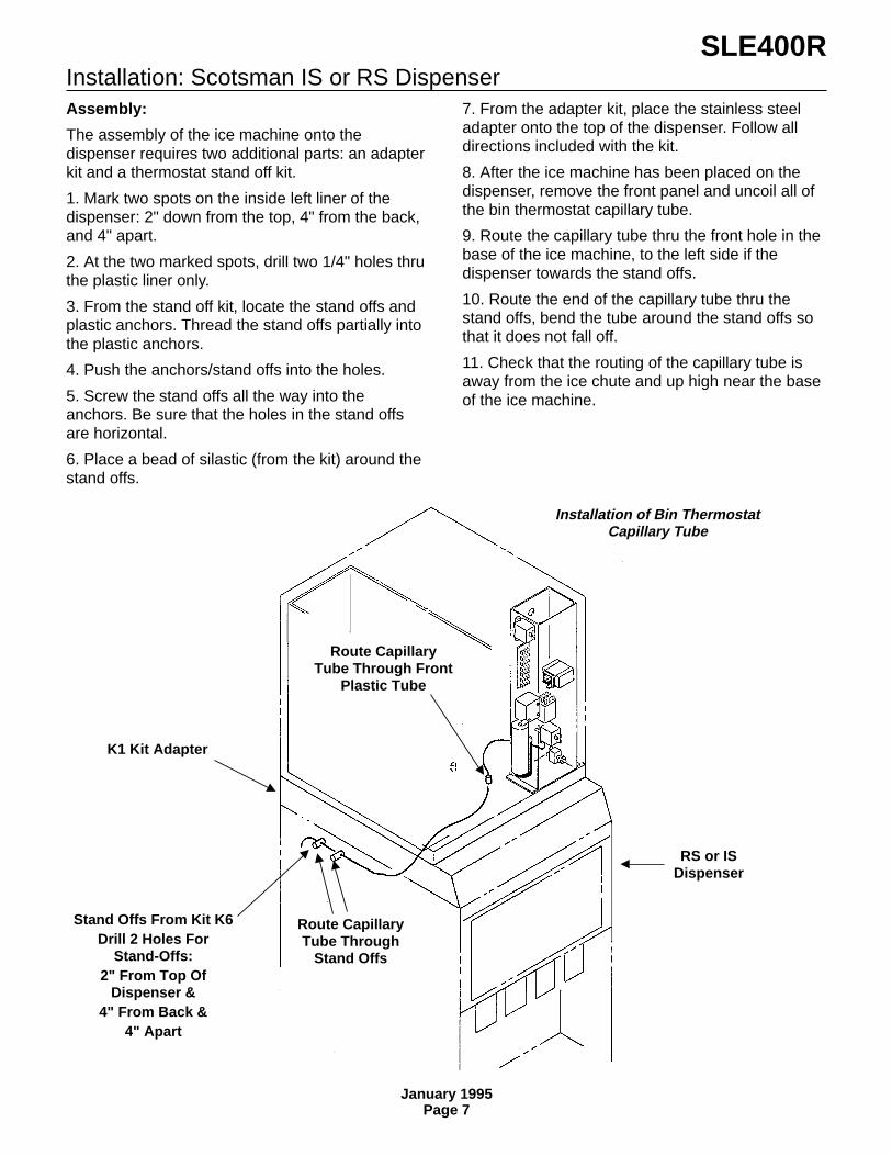
Installation: Scotsman IS or RS DispenserAssembly:
The assembly of the ice machine onto thedispenser requires two additional parts: an adapterkit and a thermostat stand off kit.
1. Mark two spots on the inside left liner of thedispenser: 2" down from the top, 4" from the back,and 4" apart.
2. At the two marked spots, drill two 1/4" holes thruthe plastic liner only.
3. From the stand off kit, locate the stand offs andplastic anchors. Thread the stand offs partially intothe plastic anchors.
4. Push the anchors/stand offs into the holes.
5. Screw the stand offs all the way into theanchors. Be sure that the holes in the stand offsare horizontal.
6. Place a bead of silastic (from the kit) around thestand offs.
7. From the adapter kit, place the stainless steeladapter onto the top of the dispenser. Follow alldirections included with the kit.
8. After the ice machine has been placed on thedispenser, remove the front panel and uncoil all ofthe bin thermostat capillary tube.
9. Route the capillary tube thru the front hole in thebase of the ice machine, to the left side if thedispenser towards the stand offs.
10. Route the end of the capillary tube thru thestand offs, bend the tube around the stand offs sothat it does not fall off.
11. Check that the routing of the capillary tube isaway from the ice chute and up high near the baseof the ice machine.
Route CapillaryTube Through Front
Plastic Tube
K1 Kit Adapter
Stand Offs From Kit K6Drill 2 Holes For
Stand-Offs:2" From Top Of
Dispenser &4" From Back &
4" Apart
Route CapillaryTube Through
Stand Offs
RS or ISDispenser
Installation of Bin ThermostatCapillary Tube
SLE400R
January 1995Page 7

installation
For The PlumberSupply:
Screw the 3/8" male flare (fitting shipped inpackage inside cabinet) into the 1/4" FPT fitting atthe back of the cabinet (thread taperecommended). Connect cold potable water to thewater inlet. A hand shut off valve for inlet watershould be installed near the machine. A water filteris recommended. Flush the water line prior toconnecting to the ice machine.
Drains:
Connect a drain tube to the reservoir drain fitting atthe back of the cabinet. The drain tube from thefitting must be run separately from any other draintube. The reservoir drain is a 3/4" F.P.T. brassfitting.
Drain tube material must be rigid and meet localcode.
Traps in the bin drain line without vents ahead ofthem will cause poor draining.
The bin drain must be vented if there is a longhorizontal run (5’ or more). The reservoir drainmust be vented and not connected to the bindrain. All drains are gravity, and must have aminimum fall of 1/4" per foot of horizontal run.
Maintain the air gap required by local codebetween the end of the drain tubes and thebuilding drain receptacle.
Note: Drain tubing should be insulated to preventcondensation from forming on the tubing.
CONFORM TO ALL LOCAL CODES
Ice Storage Bin(Typical)
Bin Drain. May Be Routed FromThe Bottom On Some ModelBins. Fitting May Be Plastic.
DO NOT OVERHEAT.
Reservoir Drain3/4" FPT, Must Be Vented.
Water ShutOff Valve
3/8 Male FlareWater Inlet
Water Supply and Drain Connections
SLE400R
January 1995Page 8

Installation: Remote Condenser SystemRemote Condenser
The remote condenser may be located within 100equivalent feet of the ice machine (per theformula). Follow all local building codes for thecondenser’s location. If placed on a roof, a roofingspecialist should install it.
Precharged Lines
There are two precharged lines required for eachice machine to condenser connection: a 1/4" liquidline and a 3/8" discharge line (the discharge line isinsulated). Each contains a minor holding chargethat matches the type of refrigerant in the icemachine and in the condenser. The ice machinecontains the entire system charge in the receiver.
From the formula, plan the routing of the tubing.Do not leave any excess tubing on the roof: thecondenser must be located as close as possible tothe place where the tubing goes through the roof.
Route the tubing to the condenser and to the icemachine. Be certain that there is no metal to metalor tight tube to tube contact between the liquid anddischarge lines.
Coil excess tubing inside the building in ahorizontal spiral.
If there is considerable excess tubing, it should becut out before the tubing is connected to the icemachine. Be certain to evacuate the tubing beforeconnecting to the ice machine or to the remotecondenser.
Connections:
Remove plastic caps from condenser, tubingconnections and from the ice machine’s refrigeranttubing connections. Lubricate all threads ando-rings with refrigeration oil.
Tighten all fittings until a significant resistance isfelt. Then using two wrenches, (one holding thetubing so that it does not rotate) tighten theconnections 1/4 turn more.
Check fittings for leaks and have the roof holesealed.
Wiring:
The remote condenser fan motor takes its powerfrom the ice machine. Wire per electrical codesand the wiring diagram.
Installation of Remote Condenser
RemoteCondenser
Pre-ChargedLine Set
SLE400R
January 1995Page 9

Installation
For The ElectricianThis unit must be on a separate 230 volt AC 60cycle single phase power supply. The maximumfuse size for this circuit is listed on the nameplate,and per the nameplate use fuses, or HACR circuitbreakers.
The remote condenser fan motor is powered fromthe ice machine, thru the junction box at the backof the ice machine.
To make the electrical connections:
1. Remove the right top panel.
2. Remove the junction box cover.
3. Make the electrical connections to the wires inthe junction box. A ground screw is provided in thejunction box.
Follow All Local Codes - This Unit Must BeGrounded . Usually a licensed electrician will berequired to connect the electrical service.
The remote condenser fan motor requires anelectrical connection in the ice machine junctionbox. See wiring diagram.
Remote wiring must be in liquid tight or rain proofconduit as required by local codes.
The fan motor voltage is 208-230.
An appropriate outdoor junction box may berequired to be added to the remote condenser.
Power Supply for Ice Makerand Condenser
Junction Box
Remote ElectricalConnection
SLE400R BACK VIEW
SLE400R
January 1995Page 10

After Utility Connections1. Level the cabinet, use the leg levelers on theend of the legs to adjust the cabinet height. (Legsshould have been installed when the bin wasunpacked).
2. Wash out the bin. If desired, the interior of thebin could be sanitized.
Final Check List1. Is the ice maker cabinet in a room whereambient temperatures are within the minimum andmaximum temperatures specified?
2. Has the water supply been connected?
3. Is the water pressure adequate?
4. Have the water connections been checked forwater leaks?
5. Have the drain connections been made?
6. Have the drain connections been checked forleaks?
7. Is the cabinet level?
8. Is the ice machine connected to a 230 voltelectrical power supply and is the ice machine theonly load on that circuit?
9. Has all of the shipping material been removedfrom the inside of the cabinet?
10. Has the bin thermostat been installed?
11. Has the remote condenser been installed in anacceptable location?
12. Have the precharged tubes been connected?
13. Has the ice maker to remote condenserelectrical connection been made?
14. Has the bin and cabinet been wiped clean andsanitized?
15. Has the Customer Evaluation & WarrantyRegistration form been properly filled out? Checkfor correct model and serial numbers from thenameplate, then mail the completed form toScotsman.
16. Has the owner/user been given the name andtelephone number of the authorized ScotsmanService Agency serving that location?
SLE400R
January 1995Page 11

Component LocationMany components are serviceable from the frontwithout removing the side panels.
Behind the front panel:
• Water pump• Inlet water valve• Reservoir• Evaporators• Water distributor pan• Ice size control adjustment• ICE/OFF/WASH switch• Control box
Ice Thickness Control
ICE/OFF/WASH Switch
Bin Thermostat
Water DistributorPan
Bin ThermostatBracket
Water Inlet Valve& Strainer
Water Pump
Control Box
Component Location
Drain Elbow
Control Box Detail
HighPressureCut Out
HarvestRelay
BinThermostat
Ice/Off/WashSwitch
Ice SizeThermostat
CompressorRelay
Contactor
SLE400R
January 1995Page 12

Initial Start UpAfter the final check list has been gone through,the ice machine may be started up.
1. Open the water shut off valve; the inlet watervalve will open, and water will flow into thereservoir..
2. Switch on the electrical power.
3. Remove the front panel.
3. Locate the ICE/OFF/WASH switch,switch it to WASH.
4. The water pump will begin to pumpwater over the evaporators.
5. Allow the reservoir to refill. Normal water level is1/8" below the high point of the lower curve of thesiphon u-tube.
6. Switch the ICE/OFF/WASH switch to OFF.
7. Check the action of the siphon. The water levelin the reservoir should drop to the bottom curve ofthe U-bend (normal water level) in about 2minutes. If not, check for proper drain tubeconnections.
8. Remove right side panel.
9. Remove cap from “king” or service valve on thereceiver, and open the valve.
10. Switch the ICE/OFF/WASH switch to ON.
11. The remote fan motor will begin to turn, andwarm air will be discharged from the top of theremote condenser.
12. The water temperature in the reservoir willsoon be 320F., and ice should begin to form on theevaporators.
13. Allow the ice machine to operate for about 20minutes. The ice should be fully formed andshould be harvested within a few minutes.
14. After harvest, check the ice cube size.Compare a fresh cube to the diagram on theback of the front panel. If needed, adjust thecube size by loosening the set screws and movingthe ice thickness probe adjustment plate.
Move the adjustment plate down for smallercubes and up down for larger.
For proper operation, the ice thickness should beset to the 1 11 ⁄16" diameter.
The machine is designed to harvest cubes ofonly the correct thickness.
Cubes TooThick
Correct Size &Shape
Cubes TooThin
1 11 ⁄16"
Cube Size Diagram
Ice Size Adjustment
SetScrews
Ice Thickness ProbeAdjustment Plate:
Move UP for LargerCubes,
DOWN for SmallerCubes
SLE400R
January 1995Page 13

Initial Start UpNote: If the first batch of cubes are not all uniformdiscs, some ice machine cleaner should be addedto the reservoir.1. After ice has been harvested, but before newcubes begin to form, switch the ICE/OFF/WASHswitch to WASH.2. Add 4 oz. of ice machine cleaner to thereservoir. Allow unit to operate that way for 10minutes.3. Switch ICE/OFF/WASH switch to OFF4. Shut the water supply off.5. Remove the splash guard, and drain thereservoir by removing the drain elbow.7. Replace all parts, turn on the water andmove ICE/OFF/WASH switch to ICE. The nextbatch of ice should be uniform.
13. Check harvest. The machine will have toharvest all of the cubes before it goes back into thefreeze cycle.
14. Check operation of the bin control circuit byholding ice on the bin control tube in the bin.
If the ice maker does not stop within 1 minute,while keeping ice on the thermostat, rotate the binthermostat shaft counter clockwise until the icemaker does stop. Remove the ice from thecapillary tube; the ice maker should restart within 2minutes. If it does not, rotate the adjusting shaftclockwise until the machine starts.
15. Replace all the panels. The ice machine is nowready for automatic operation.
Electrical Sequence:Freeze Cycle:
During the first part of the freeze cycle, the icemachine compressor, fan motor and water pumpare operating.
Assume the bin thermostat is open (low ice), relayK1 will NOT have power thru its coil and K1contacts 6-2 will be closed, connecting power tothe ice size thermostat and the liquid line valve coil.
The ice size thermostat contact 2-3 are closed,connecting power to the fan motor and the pumpmotor.
The Harvest Termination Thermostat is closed toNC, but there is no power thru it.
The ice size thermostat heater is on, and thecompressor contactor coil is energized.
Harvest:In the harvest cycle, the compressor is operating,and the hot gas valve is energized. The fan andand pump are off. The bin thermostat is still open.
The when the ice near the ice size thermostatsensing tube grows large enough to force waterover the sensing tube, that tube looses heat, andat 38oF. contacts 2-3 open and 2-1 close.
This removes power from the water pump andremote fan and connects power to the relay coil.When the relay coil has power, it connects powerto the hot gas valve coil.
The harvest termination switch is closed, andpower flows thru it to the relay coil. This keeps therelay energized, even when the ice size thermostatswitches contact position as a result of ice fallingaway from the sensing tube.
The unit stays in the harvest cycle until thethermodisc on the suction line warms up to 55oF.,At that time the defrost themodisc switches to NOand the harvest cycle is terminated. If the binthermostat is still open, relay K1 will still not havepower and the unit will go back into the freezecycle. If relay K1 has power, it shuts off the icemachine by cutting power to the liquid line valve,after the unit pumps down, the low pressurecontrol shuts off the compressor.
Whenever there is ice on the bin thermostat, itcloses a circuit to the coil of relay K1 and stops theice making process at the end of a harvest cycle.
The crankcase heater is on at all times.
Siphon Tube Schematic
U-Tube AdjustedHere = No Purge
Siphon Breaker Hole
U-Tube Here =Maximum Purge
Water LevelAt Harvest
Water Level WithPump ON
Water Inlet
1/8 - 1/4
Bottom ofReservoir
ElbowDrain Outlet
SLE400R
January 1995Page 14

Maintenance, Cleaning and SanitizingCleaning Schedule:
•Scrub the outside of the cabinet once a weekwith soap and water.
•Sanitize the bin interior once a month.•Clean the water system and air cooled
condenser a minimum of twice per year. If inan area of high mineral concentration in thewater supply, clean water system 4 times ayear.
Inlet Water Valve Screens
If a restriction of incoming water is suspected,there may be a strainer in the water line; thestrainer screen should be inspected for restrictingminerals. Water filters should be changed.
Air Cooled Condenser:
Shut the unit off.
The fins of the condenser will become fouled withdirt, and must be cleaned. A vacuum cleaner witha soft brush attachment will extract most loosedust stuck to the surface of the condenser fins..
Ice Storage Bin
The interior liner of the bin is in contact with a foodproduct: ice. The storage bin must be cleanedregularly to maintain a sanitary environment.Once a week cleaning with soap and water, a hotwater rinse and an air dry is a basic procedure.
Every 30 days, the liner should be sanitized with acommercial ice machine sanitizer, according to thedirections of the sanitizer, or with a solution ofhousehold bleach and water:
1. Mix the bleach and water using the ratio of twoounces of bleach to two gallons of water.
2. Wipe all interior surfaces of the ice storage binwith the bleach and water.
3. Allow to air dry.
To Remove Scale:
1. Mix a cleaning solution of 4 ounces of ScotsmanIce Machine Cleaner to 4 pints of warm(950F.-1100F.) water.
2. Using rubber gloves, dip a nylon scouring padinto the cleaning solution and scrub the scale offthe liner.
3. After the scale has been removed, rinse allsurfaces inside the bin with clean, potable water.
Stainless Steel Bin Liner
The stainless steel liner of the bin will requireperiodic cleaning. Chemicals in the water supply,such as chlorine, cause brown stains to appear onthe surface of the stainless steel parts.
1. General Cleaning - staining is usually removedby washing the parts with ordinary cleaningpowder such as Bon-Ami or Copper-Glo andwater. After cleaning, rinse with clear water.
2. Water treatment. The chlorine enters themachine from the municipal water supply. It can beremoved from the water supply by using acharcoal or activated carbon water filter to treat thewater to the ice machine. If staining is severe,filters of this type are recommended.
Exterior Cabinet Cleaning:
The exterior cabinet may be cleaned by scrubbingwith soap and water. Do not use cleanerscontaining petroleum products.
A nylon type brush may be used to scrub stubborndeposits.
SLE400R
January 1995Page 15

Cleaning: Ice Machine Water SystemDissolve and Remove Minerals:
1. Remove front panel.
2. Move the ICE/OFF/WASH switch to OFF.
3. Remove the splash guard.
4. Shut the water supply off by pushing the watervalve button in.
5. Drain the water from the sump by removing thedrain elbow.
6. Disconnect hose from the water distributor pan,and remove the water distributor pan.
7. Mix a solution of 5 oz. ice machine cleaner and1 gallon of warm (95oF. - 115oF.) water.
8. Wash the splash guard, drain elbow and waterdistributor pan with the ice machine cleaner/watersolution.
9. With the solution of ice machine cleaner andwater, wash the refrigeration tubing, liner,evaporators, support brackets and the water pumpassembly. Use the brush and/or a clean cloth.
10. Replace the drain elbow.
11. Open the water supply by pushing the watervalve button in (to its original position) and allowthe sump to refill.
12. Add 5 oz. ice machine cleaner to the sumparea.
13. Replace the water distributor pan and splashguard. Be certain the hose to water distributor panis connected to pan.
14. Move the ICE/OFF/WASH switch to wash andallow the solution to circulate for 15 minutes, thenmove the ICE/OFF/WASH switch to OFF.
17. Remove the splash guard.
15. Shut the water supply off by pushing the watervalve button in.
16. Drain the water from the sump by removing thedrain elbow.
Sanitize:
17. Remove the water distributor pan.
18. Mix a sanitizer solution of 1 ounce ofhousehold bleach to 2 gallons of warm (95oF. -115oF.) water
19. Wash the splash guard and the waterdistributor pan with the solution of sanitizer. Allowto air dry.
20. With the sanitizer solution, wash therefrigeration tubing, liner, evaporators, supportbrackets and water pump assembly; use the brushand/or a clean cloth.
21. Replace the water distributor pan and splashguard. Be certain that the hose to the waterdistributor pan is tightly connected to the pan, andthat the flow washer in the hose is not in sideways.
22. Replace the drain elbow.
23. Add ice machine sanitizer solution to the sumparea until it is full.
24. Move the ICE/OFF/WASH switch to WASHadd more sanitizer solution to the sump area untilit is full again.
25. After 5 minutes, move the ICE/OFF/WASHswitch to OFF.
26. Remove the splash guard.
27. Drain the water from the sump by removing thedrain elbow.
28. Replace the drain elbow and splash guard
29. Open the water supply by pushing the watervalve button in (to the original position) and allowthe sump to refill.
30. Move the ICE/OFF/WASH switch to ICE.
31. Replace the front panel.
32. Discard first batch of ice and all other batchesuntil all traces of cleaner and sanitizer disappear.
Scotsman Ice MachineCleaner containsacids. Thesecompounds maycause burns.If swallowed, DO NOTinduce vomiting. Givelarge amounts of wateror milk. Call Physicianimmediately. In case ofexternal contact, flushwith water.KEEP OUT OF THE
SLE400R
January 1995Page 16

How It Works:Refrigeration: Freeze Cycle:
From the compressor, hot discharge gas ispumped to the remote air cooled condenser.
At the condenser, if the discharge pressure is over225 PSIG, the discharge gas will flow thru thecondenser coil. Heat from the refrigerant flows intothe air, and the refrigerant condenses into a liquid.
If the discharge pressure is below 225 PSIG, therefrigerant will not flow thru the coil, but will beforced into the liquid line.
From the condenser the liquid refrigerant flowsthrough the liquid line to the liquid line check valve.When the machine is on, the check valve is opento flow from the condenser to the receiver.
From the receiver, refrigerant then flows to themetering device - a thermostatic expansion valve.
At the expansion valve, the liquid refrigerantpasses from a high pressure zone to one ofrelatively low pressure, and in the low pressurezone it evaporates. The low pressure zone wherethe refrigerant evaporates is the evaporator. Whenthe refrigerant evaporates, it absorbs heat from themetal parts of the evaporator and the water flowingover it.
From the evaporator, the refrigerant flows back tothe compressor through the suction line.
Note: During the time that the machine is off, thethe pump down system (liquid line valve) keepsthe refrigerant out of the low side of the system,and the liquid line check valve keeps liquidrefrigerant from flowing back into the liquid line andremote condenser.
Water :
Water flows into the ice machine from its inletconnection at the back of the cabinet, through theinlet water valve and into the reservoir. The waterin the reservoir is pumped up and through thewater distributor tube at the top of the evaporators.From there, the water flows over both sides of theevaporators and back into the reservoir.
Melted ice and water spills into the bin flowthrough a drain in the base of the bin to theexterior drain connection at the back of the cabinet.
Refrigeration: Harvest Cycle:
The ice maker continues to freeze the water intoice until the ice next to the ice size thermostatprobe has become thick enough to force waterover the probe. After the cold water has reducedthe temperature of the probe to 380F., the ice sizethermostat will switch the machine into the harvestcycle.
During the harvest cycle, the refrigerant flows fromthe condenser, through the discharge line to abranch in the line containing the Hot Gas Valve.This valve is Open during the harvest cycle,allowing the hot discharge gas to bypass thecondenser and enter the evaporator at its inlet.
The hot discharge gases warm up the evaporatorenough to allow the surface of the ice frozen to theevaporator to melt. The remaining ice will then falloff into the bin.
During the Harvest Cycle, the water level rises,filling the reservoir over the siphon tube andsiphoning some of the reservoir water out to thedrain. The harvest cycle continues until the suctionline warms up enough to cause the harvesttermination thermostat to switch the machine backinto the freeze cycle.
SLE400R
January 1995Page 17

Technical Characteristics
Typical Cycle Time•17 minutes @ 70oF. air and 50oF. water•24 minutes @ 90oF. air and 70oF. water
Typical Harvest Ice Weight•4 pounds .
Typical Low Side Pressure• 22 - 23 PSIG just before harvest (beginning of freeze may be 45 - 50 PSIG)
Typical Freeze Cycle Discharge Pressure• 240 - 260 PSIG• Minimum (low temps) = 225 PSIG
Refrigerant Charge:• 136 ounces R-404A
Harvest Time• Normally 11⁄2 to 2 minutes. Depends upon time required to warm suction line to 55oF.
Typical Suction Pressure, In Harvest:• 110- 120+ PSIG
Typical Discharge Pressure, In Harvest:• 130 - 150 PSIG
Typical Compressor Amp Draw:• 4 - 5 during freeze cycle; 5 - 6 during the harvest cycle
Compressor:• Copeland: RS64C1E-CAV-214
Thermostatic Expansion Valve•Superheat is 3o - 6oF.
Pump down pressure control•Cut Out at about 10 PSIG•Cut In at about 25 PSIG
Bin Thermostat•Cut In to shut off machine at 35oF., cut out at 39oF.. Adjustable warmer.
Ice Size Thermostat:• Switches to harvest cycle with temperature fall to 38oF.. Resets at 43oF.
Ice Size Heater•Adds heat to ice size thermostat to prevent premature harvest.
Harvest Termination Thermostat• Switches from contacts C-NC to contacts C-NO to switch to freeze cycle with temperature rise to
55oF. Resets at 40oF.
SLE400R
January 1995Page 18

Service Diagnosis:
SYMPTOM POSSIBLE CAUSE PROBABLE FIXNo ice is made, nothing operates Unit off, due to no power Restore power
Unit off, due to ICE/OFF/WASHswitch in OFF position
Switch ICE/OFF/WASH switch toICE
Unit off, due to bin thermostatclosed
Check temperature at binthermostat bracket, if warmer than40o F., thermostat should beopen. Adjust/replace thermostat.
Unit off, due to high pressure cutout open
Check fan motor.
No ice, compressor off No cooling due to compressor notoperating
Check compressor for voltage,continuity, and operation. Checkstarting components. Replace iffound to be faulty.
If no voltage, check contactor,replace if coil or contacts open.
Check temperature ofcompressor, if hot may be lack ofrefrigerant, defective TXV orcompressor
Unit off, due to low pressure(pump down) control open.
Check liquid line valve coil forpower and/or continuity
No ice is made, compressor isoperating
No water due to water turned off. Reconnect water supply
No water due to water filterplugged.
Replace water filter
No water due to strainer screenplugged
Clean out inlet screen
No water due to inlet water valvewill not open
Replace valve
Water in reservoir, but no waterover evaporators
Water pump does not work,replace pump
No cooling at evaporator due tohot gas valve leaking thru
Replace hot gas valve
No cooling at evaporator due tofan not turning
Check & replace fan motor.
Fan and pump do not havepower; hot gas valve opens andcloses.
Coil or relay open, replace relay.
No cooling at evaporator due todirty condenser
Clean condenser
No cooling due to compressor notpumping
Check system pressures, replacecompressor if not pumping
SLE400R
January 1995Page 19

SYMPTOM POSSIBLE CAUSE PROBABLE FIXNo ice compressor is operating No cooling due to low refrigerant
chargeLocate leak, recover remainingrefrigerant, replace dryer,evacuate and weigh in nameplatecharge.
Ice is made, but not harvested. Ice size thermostat contacts donot switch position
Ice not made near thermostatprobe due to water distributorholes restricted. Clean waterdistributor pan.
Thermostat defective, replace it
Ice will not slide down ice rackdue to minerals on rack.
Clean machine with ice machinecleaner.
Ice will not slide down ice rackdue to ice rack out of position
Reposition ice rack
Ice will not slide down ice rackdue to bent ice rack
Replace ice rack
Lack of heat during harvest cycledue to unit in air temp. less than550F.
Warm up air or move machine.
Lack of heat during harvest due towater flowing thru water cooledcondenser
Replace water regulating valve
Lack of heat during harvest due tolack of refrigerant
Check low side pressure duringharvest. If low either the charge islow or the hot gas valve does notopen fully. If charge is theproblem, locate leak, recoverremaining refrigerant, repair leak,replace drier, evacuate and weighin nameplate charge.
Lack of heat during harvest due tohot gas valve not opening fully.
Check low side pressure duringharvest. If low either the charge islow or the hot gas valve does notopen fully.
Ice does not slide down face ofevaporator due to minerals onevaporator surface
Clean water system with icemachine cleaner
Harvest cycle too short due toharvest termination thermostatopens at too low a temperature.
Replace harvest terminationthermostat
Service Diagnosis:SLE400R
January 1995Page 20

Service Diagnosis:
SYMPTOM POSSIBLE CAUSE PROBABLE FIXIce is made, but will not harvest Will not harvest due to hot gas
valve not opening.Check for voltage to coil inharvest, if there is voltage replacehot gas valve
Slow/incomplete harvest due tohot gas valve not fully open.
Check low side pressure inharvest, replace hot gas valve iftoo low with correct ref. charge.
Makes ice, but very little High discharge pressure, due todirty condenser; faulty fan motor;
Check for causes of highdischarge pressure and correct.
Inlet water temperatures androom ambient very high
Advise user, suggest additionalroom cooling.
Long freeze cycle due to hot gasvalve leaking thru.
Check temperature of tubes toand from hot gas valve; thereshould be a temperature dropacross the valve in the freezecycle. Replace valve if temps arenearly equal.
Compressor inefficient Check/replace compressor
Cubes are wrong size/shape Ice size thermostat not adjustedproperly
Adjust ice size thermostat; usegauge shipped with machine
Freeze cycle too short due toheater open
Check/replace heater on ice sizethermostat probe tube.
Water system is restricted withminerals
Clean water system withScotsman Ice Machine Cleaner
Ice thickness probe tube coveredwith minerals
Clean tube with ice machinecleaner
Not enough water Check water supply pressure
Check water supply for restrictions
Too much superheat Check superheat, replace TXV iftoo high.
Check hot gas valve for leak-thru;replace if leaks thru.
Ice fused together in bin Ice in bin too long Advise user to pour water on iceto ease removal
Too many minerals in water Suggest water treatment to user.
Unit does not shut off Bin control will not close Check & replace bin control
K1 relay coil open Check & replace K1 relay
SLE400R
January 1995Page 21

Removal and ReplacementIce Size Thermostat:
Before replacing the ice size thermostat, it shouldbe positively determined that it is at fault.
1. Disconnect electrical power.
2. Remove the front panel.
3. Remove the control box cover.
4. Locate the ice size thermostat.
5. Remove the two screws holding the control tothe control box, and lift the control out.
6. Pull the three wires off the posts of the ice sizethermostat.
7. Follow ice size thermostat capillary tube to icesize probe.
8. The end of the ice size thermostat is inserted ina tube. Pull it out of the tube.
9. Follow the capillary tube of the ice sizethermostat and pull it thru the insulated wall andthe grommet in the side of the control box.
10. Remove thermostat from control box.
11. Replace the ice size thermostat with the properpart number, following the above steps from 9-1.
Primary Resistor (Heater)
1. Disconnect electrical power.
2. Disconnect the primary resistor’s yellow wirefrom terminal #4 and the white wire from terminal#1. Pull the two wires out of the control box andthru the insulated wall.
3. Mark location of probe tube bracket.
4. Remove two screws and the probe tube bracketfrom the evaporator.
5. Remove the plastic sleeve and heater from thetube.
6. Replace heater and plastic tubes.
7. Place probe tube bracket on evaporator in itsoriginal position. Probe tube must be inserted intoplastic guide attached to evaporator.
8. Replace wires.
9. Reconnect power, restart ice maker. Check icesize.
Electrical shockhazard.Electrical shock cancause personal injury.Disconnect powerbefore beginning toservice components.
Heater
Probe Tube Bracket
Evaporator
Replacement of Ice Size Thermostat
CapillaryTube
SLE400R
January 1995Page 22

Removal and ReplacementWater Pump
The pump provides the force to move the waterfrom the reservoir to the freezing surface. Thepump does not need oil, but if it becomes noisy,overheats, or will not pump it should be replaced.Be certain to confirm electrical faults with avoltmeter or ohmmeter before replacing the pump.The pump should be operating whenever themachine is in the freeze cycle.
1. Unplug or disconnect the electrical power.
2. Unplug the pump from its connection.
5. Loosen the two fasteners holding the cover tothe wall.
6. Remove pump cover from the machine.
7. Pull discharge hose from pump discharge port.
8. Remove pump from ice machine.
9. Reverse above steps to replace.
Inlet Water Valve
The valve may plug-up from minerals in the water,and should then be cleaned rather than replaced.There is also a strainer located above the floatvalve that may be cleaned.
1. Shut off the water supply.
2. Unscrew the fitting at the top of the valve, andpull the water inlet tube out of the valve body.
3. Remove the screws holding the valve bracket tothe liner.
4. Remove the valve from the ice machine.
5. Reverse the above steps to reassemble.
Electrical shockhazard.Electrical shock cancause personal injury.Disconnect powerbefore beginning toservice components.
Siphon “U” Tube
Float Valve
ThumbScrews
Pump Cover
Replacement of WaterPump
SLE400R
January 1995Page 23

Removal and Replacement: Refrigeration SystemGeneral Information
Work on the refrigeration system should only bedone when it is certain that the system needsrepair.
•This ice machine use R-404A (HP62)refrigerant and the compressor uses PolyolEster oil.
•Do NOT use mineral oil in this refrigerationsystem.
•R-404A is a “near azeotrope” and thereforeliquid charging is required.
•When the system is serviced, a special liquidline dryer is required.
•Polyol ester oil absorbs water very easily, andwhen the system is opened for service, itmust be re-sealed as soon as possible (15minutes maximum).
•Special leak detection equipment is requiredto locate small refrigerant leaks. Usually aleak detector capable of detecting aHalongenated refrigerant or HFC-134a willwork. Check with the leak detectormanufacturer if in doubt.
•As with any other refrigerant, do not mixR-404A with pressurized air when leak testing.
•Evacuate the system to 200 microns beforecharging.
•Weigh the nameplate charge into the receiver.
SLE400R
January 1995Page 24