6 removal and replacement
TRANSCRIPT
6 Removal and replacement
Chapter contents
Introduction. . . . . . . . . . . . . . . . . . . . . . . . . . . . . . . . . . . . . . . . . . .145Removal and replacement strategy . . . . . . . . . . . . . . . . . . . . .145Repair notices . . . . . . . . . . . . . . . . . . . . . . . . . . . . . . . . . . . . .145Caution regarding electrostatic discharge (ESD). . . . . . . . . . .145Required tools . . . . . . . . . . . . . . . . . . . . . . . . . . . . . . . . . . . . .146Types of screws . . . . . . . . . . . . . . . . . . . . . . . . . . . . . . . . . . . .147
Consumable assemblies . . . . . . . . . . . . . . . . . . . . . . . . . . . . . . . .148Covers, drawers, top, and front assemblies . . . . . . . . . . . . . . . . . .149
Top cover . . . . . . . . . . . . . . . . . . . . . . . . . . . . . . . . . . . . . . . . .149Left side cover . . . . . . . . . . . . . . . . . . . . . . . . . . . . . . . . . . . . .150Right side cover . . . . . . . . . . . . . . . . . . . . . . . . . . . . . . . . . . . .151Rear door. . . . . . . . . . . . . . . . . . . . . . . . . . . . . . . . . . . . . . . . .152Right rear cover . . . . . . . . . . . . . . . . . . . . . . . . . . . . . . . . . . . .153Drum drawer (top drawer) cover . . . . . . . . . . . . . . . . . . . . . . .154ITB drawer (middle drawer) cover . . . . . . . . . . . . . . . . . . . . . .156Control panel . . . . . . . . . . . . . . . . . . . . . . . . . . . . . . . . . . . . . .158Front right cover . . . . . . . . . . . . . . . . . . . . . . . . . . . . . . . . . . . .159ITB drawer (middle drawer) . . . . . . . . . . . . . . . . . . . . . . . . . . .157Radio Frequency Interference (RFI) shield . . . . . . . . . . . . . . .160Laser/scanner assembly . . . . . . . . . . . . . . . . . . . . . . . . . . . . .161DC controller . . . . . . . . . . . . . . . . . . . . . . . . . . . . . . . . . . . . . .162Developing PCB. . . . . . . . . . . . . . . . . . . . . . . . . . . . . . . . . . . .163Top cover switch assembly. . . . . . . . . . . . . . . . . . . . . . . . . . . .165Drum drawer (top drawer) assembly . . . . . . . . . . . . . . . . . . . .168Densitometer assembly . . . . . . . . . . . . . . . . . . . . . . . . . . . . . .171
Right side assemblies . . . . . . . . . . . . . . . . . . . . . . . . . . . . . . . . . .173Formatter . . . . . . . . . . . . . . . . . . . . . . . . . . . . . . . . . . . . . . . . .173Formatter PCB. . . . . . . . . . . . . . . . . . . . . . . . . . . . . . . . . . . . .174Formatter pan assembly . . . . . . . . . . . . . . . . . . . . . . . . . . . . .175Power supply . . . . . . . . . . . . . . . . . . . . . . . . . . . . . . . . . . . . . .179High-voltage power supply. . . . . . . . . . . . . . . . . . . . . . . . . . . .180
Chapter 6 Removal and replacement 143
Drum drive assembly . . . . . . . . . . . . . . . . . . . . . . . . . . . . . . . .182Large fan housing . . . . . . . . . . . . . . . . . . . . . . . . . . . . . . . . . .185Carousel drive assembly . . . . . . . . . . . . . . . . . . . . . . . . . . . . .187Paper size switch PCB. . . . . . . . . . . . . . . . . . . . . . . . . . . . . . .189
Left side assemblies . . . . . . . . . . . . . . . . . . . . . . . . . . . . . . . . . . . .190Drawer switch assembly. . . . . . . . . . . . . . . . . . . . . . . . . . . . . .190Paper feed PCB . . . . . . . . . . . . . . . . . . . . . . . . . . . . . . . . . . . .191Fuser motor (M1) . . . . . . . . . . . . . . . . . . . . . . . . . . . . . . . . . . .194Paper path motor (M2) . . . . . . . . . . . . . . . . . . . . . . . . . . . . . . .196Paper pick solenoid (SL2) . . . . . . . . . . . . . . . . . . . . . . . . . . . .197ITB cleaning roller clutch (CL3) . . . . . . . . . . . . . . . . . . . . . . . .198ITB clutch (CL2) assembly . . . . . . . . . . . . . . . . . . . . . . . . . . . .199Transfer roller cam clutch (CL4) . . . . . . . . . . . . . . . . . . . . . . . .201Left side gears . . . . . . . . . . . . . . . . . . . . . . . . . . . . . . . . . . . . .202
Rear assemblies. . . . . . . . . . . . . . . . . . . . . . . . . . . . . . . . . . . . . . .204Large right side fan . . . . . . . . . . . . . . . . . . . . . . . . . . . . . . . . .204Left side fan . . . . . . . . . . . . . . . . . . . . . . . . . . . . . . . . . . . . . . .206Face-down assembly . . . . . . . . . . . . . . . . . . . . . . . . . . . . . . . .208
Internal assemblies . . . . . . . . . . . . . . . . . . . . . . . . . . . . . . . . . . . .209Carousel housing assembly . . . . . . . . . . . . . . . . . . . . . . . . . . .209Paper transport assembly . . . . . . . . . . . . . . . . . . . . . . . . . . . .213Paper pick rollers . . . . . . . . . . . . . . . . . . . . . . . . . . . . . . . . . . .214
144 Chapter contents

Introduction
Removal and replacement strategyThis chapter explains how to remove and replace major printer components. (HP does not support repairing individual subassemblies or troubleshooting to the component level.)
Replacement is generally the reverse of removal. Occasionally, directions for difficult or critical replacement procedures are included.
Repair notices
WARNING! Turn the printer off, wait five seconds, then unplug the power cord before servicing the printer. Failure to completely disconnect the printer could result in severe injury.
Never operate or service the printer with the protective cover removed from the scanner assembly. The reflected beam, although invisible, can damage your eyes.
Never operate the printer with any parts removed.
The sheet-metal parts can have sharp edges. Be careful not to cut yourself when handling sheet-metal parts.
CAUTION Always protect the imaging drum from light and physical contact when it is removed from the printer. HP recommends reinstalling the original cover whenever the drum is removed from the printer.
Caution regarding electrostatic discharge (ESD)
The printer contains parts that are sensitive to electrostatic discharge (ESD). Watch for the ESD reminder shown at the left when removing printer parts. Protect the parts that are sensitive to ESD with protective ESD pouches.
Chapter 6 Removal and replacement 145
Determining the printer versionTwo versions of the HP Color LaserJet 4500 series printers are available. To accurately perform removal and replacement procedures or determine the correct part for reordering, you will need to know the version of the printer that is being serviced. To identify the printer, check the serial number located at the rear of the printer. All printers will have US or JP in the first two positions of the serial number (e.g., USBB123456). Newer versions of the HP Color LaserJet 4500 printers will have an “H” or higher letter in the third position (e.g., USHB123456). If the letter in the third position in the serial number is “B”, “C”,”D”, or “F”, then you have an older version.
Required toolsThe following tools are needed to service the printer:
� Phillips #2 magnetized screwdriver (152-mm [6-inch] shaft)
� Small flat-blade screwdriver
� Small needle-nose pliers
� ESD strap
� Penlight (optional)
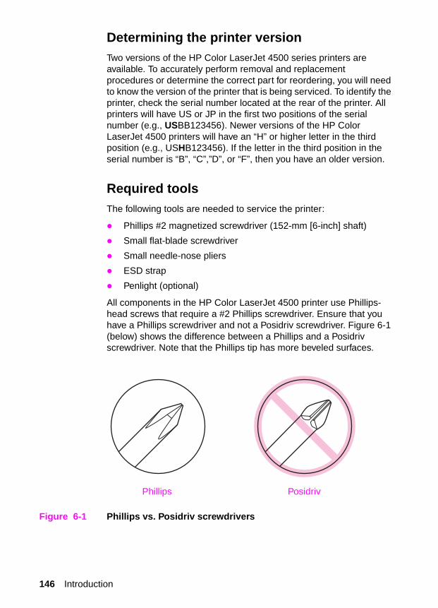
All components in the HP Color LaserJet 4500 printer use Phillips-head screws that require a #2 Phillips screwdriver. Ensure that you have a Phillips screwdriver and not a Posidriv screwdriver. Figure 6-1 (below) shows the difference between a Phillips and a Posidriv screwdriver. Note that the Phillips tip has more beveled surfaces.
Figure 6-1 Phillips vs. Posidriv screwdrivers
PosidrivPhillips
146 Introduction

Types of screwsTable 6-1 describes the screws used in the printer and provides guidelines to help determine where each type of screw is used. The screws can vary in length depending on the thickness of the material being fastened.
Always note where each type of screw is located and replace each one into its original location.
Table 6-1 Types of screws
Illustration Description Uses
Screw, machine w/washer To hold plastic to metal.
example: printer skins
Screw, self tapping To hold plastic to plastic.
example: control panel
Screw, trus head To hold sheet metal to sheet metal.
example: formatter pan
Retaining ring (e-type)
Chapter 6 Removal and replacement 147

Consumable assemblies
The user replaces consumable assemblies as part of periodic maintenance. Chapter 4 explains the maintenance procedures.
Note The printer tracks the amount of use on some of its user-replaceable parts by keeping a page count. Swapping consumable assemblies between printers might cause a misrepresentation of consumable assembly life values and is not recommended.
CAUTION Hewlett-Packard recommends the use of HP products in this printer. Use of non-HP products may cause problems requiring service that is not covered by the Hewlett-Packard warranty or service agreements.
Table 6-2 Approximate replacement interval for consumable items
Consumable Printer message Page count Approximate time period 1
1. Approximate lives are based on 2,000 pages per month.
To install
Black (K) toner cartridge
TONER K LOW or TONER K OUT
9,000 pages 2
2. The approximate average A4/letter-size page count is based on 5% coverage of individual toner colors. Page counts are only estimations; usage conditions and print patterns can cause results to vary.
4.5 months See page 80.
Cyan (C) toner cartridge
TONER C LOW or TONER C OUT
6,000 pages 2 3 months See page 80.
Magenta (M) toner cartridge
TONER M LOW or TONER M OUT
6,000 pages 2 3 months See page 80.
Yellow (Y) toner cartridge
TONER Y LOW or TONER Y OUT
6,000 pages 2 3 months See page 80.
Drum kit DRUM KIT LOW or DRUM KIT OUT
REPLACE DRUM KIT
25,000 black and white only pages, or 6,250 color pages.
12.5 months for black and white only pages, or 3 months for color pages.
See page 82.
Transfer kit TRANSFER KIT LOW or TRANSFER KIT OUT
REPLACE KIT
100,000 black and white only pages, or 25,000 color pages.
50 months for black and white only pages, or 12.5 months for color pages.
See page 83.
Fuser kit FUSER KIT LOW orFUSER KIT OUT
REPLACE KIT
100,000 black and white only pages, or 50,000 color pages.
50 months for black and white only pages, or 25 months for color pages.
See page 86.
148 Consumable assemblies

Covers, drawers, top, and front assemblies
Top cover
To remove the top cover
1 Open the drum drawer (top drawer) until it clears the top cover, and then remove the imaging drum, protecting it from light.
CAUTION Exposure to light for more than 15 seconds can seriously damage the imaging drum.
2 Push the release button on the left side of the printer and open the top cover.
3 Open the rear door(s) of the printer.
4 Remove the two screws from the top cover as shown in Figure 6-2.
5 Lift up on the rear corners of the top cover to release the plastic retaining tabs from the side cover.
6 Rotate the back of the cover toward the left side of the printer, then lift to remove it.
Top cover replacement tip� When replacing the top cover, be sure to properly seat the two
plastic retaining tabs on the front of the cover.
� Be sure to firmly seat the top cover.
Figure 6-2 Top cover removal and replacement (rear view of printer)
Chapter 6 Removal and replacement 149

Left side cover
To remove the left side cover
1 Remove the top cover.
2 Open the drum drawer (top drawer) and remove the imaging drum, protecting it from light.
CAUTION Exposure to light for more than 15 seconds can seriously damage the imaging drum.
3 Open the ITB drawer (middle drawer) and tray 2.
4 Remove the two screws as shown in callout 1.
5 Carefully pull out the bottom of the cover, disengage the two tab(s) located behind the cover (see callout 2), and then lift the cover up and off.
CAUTION Be careful to not break the tabs when pulling out the bottom of the cover.
Figure 6-3 Left side cover removal and replacement
1
2
150 Covers, drawers, top, and front assemblies

Right side cover
To remove the right side cover from the printer
1 Remove the top cover.
2 Open the drum drawer (top drawer) and remove the imaging drum, protecting it from light.
CAUTION Exposure to light for more than 15 seconds can seriously damage the imaging drum.
3 Open the ITB drawer (middle drawer) and tray 2.
4 Remove the two screws shown in callout 1, Figure 6-4.
5 Carefully pull out the bottom of the cover, and disengage the two tab(s) located behind the cover (see callout 2, Figure 6-4) by sliding the cover to the rear. Lift the cover up and off.
Reinstallation tip
CAUTION When reinstalling the cover, ensure that the tabs on the inside of the cover (callout 2, Figure 6-4) are seated properly by pushing in firmly on the tabs while sliding the cover forward into position.
Figure 6-4 Right side cover removal and replacement
1
2
Chapter 6 Removal and replacement 151

Rear door
To remove the rear door
1 Open the rear door of the printer.
2 Push in the retaining strap connectors to release the two plastic retaining straps attached to the inside of the rear door as shown in Figure 6-5.
3 Slide the bottom of the rear door to your right until the plastic guide-pin clears the guide-pin harness attached to the printer.
4 Remove the rear door.
Figure 6-5 Rear door removal and replacement
152 Covers, drawers, top, and front assemblies
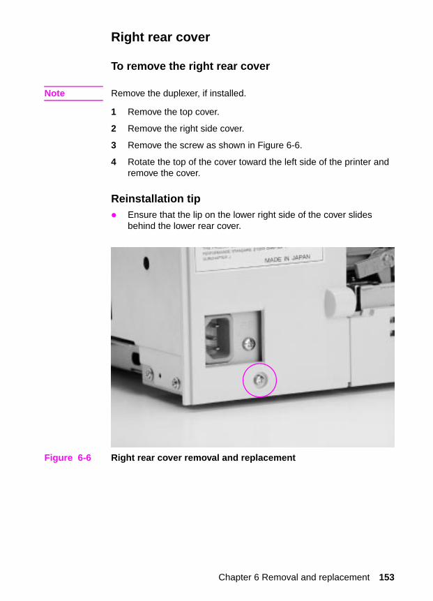
Right rear cover
To remove the right rear cover
Note Remove the duplexer, if installed.
1 Remove the top cover.
2 Remove the right side cover.
3 Remove the screw as shown in Figure 6-6.
4 Rotate the top of the cover toward the left side of the printer and remove the cover.
Reinstallation tip� Ensure that the lip on the lower right side of the cover slides
behind the lower rear cover.
Figure 6-6 Right rear cover removal and replacement
Chapter 6 Removal and replacement 153

Drum drawer (top drawer) cover
To remove the drum drawer (top drawer) cover
CAUTION Two versions of the HP Color LaserJet 4500 series printers are available. To identify which printer version you are servicing, see page 146.
1 Open the drum drawer (top drawer) and remove the imaging drum, protecting it from light.
CAUTION Exposure to light for more than 15 seconds can seriously damage the imaging drum.
2 Remove the two screws in the newer version printers (callout 1) or four screws in the older version printers (callout 2) from the inside of the drawer cover.
3 Reach beneath the drum drawer (top drawer) cover, firmly grasping beneath the center of the cover. Then, pull down slightly on the cover, rotating the bottom out toward you. Lift the cover up to remove.
Figure 6-7 Drum drawer (top drawer) cover removal and replacement
2
1
154 Covers, drawers, top, and front assemblies

Drum drawer (top drawer) cover replacement tip� When replacing the drum drawer (top drawer) cover, carefully
insert the black plastic tabs into the black plastic levers (Figure 6-8).
Note In newer version printers, insert the metal tabs (located just inside the black plastic tabs shown in Figure 6-8) into the drum drawer (top drawer) cover before latching the cover onto the bottom of the drum drawer.
Figure 6-8 Drum drawer (top drawer) cover tabs and levers
Chapter 6 Removal and replacement 155
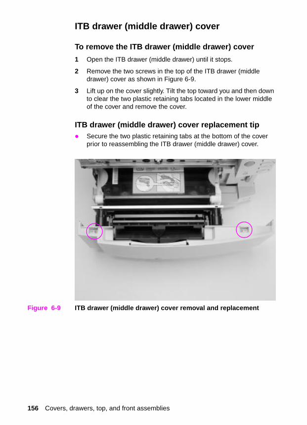
ITB drawer (middle drawer) cover
To remove the ITB drawer (middle drawer) cover
1 Open the ITB drawer (middle drawer) until it stops.
2 Remove the two screws in the top of the ITB drawer (middle drawer) cover as shown in Figure 6-9.
3 Lift up on the cover slightly. Tilt the top toward you and then down to clear the two plastic retaining tabs located in the lower middle of the cover and remove the cover.
ITB drawer (middle drawer) cover replacement tip� Secure the two plastic retaining tabs at the bottom of the cover
prior to reassembling the ITB drawer (middle drawer) cover.
Figure 6-9 ITB drawer (middle drawer) cover removal and replacement
156 Covers, drawers, top, and front assemblies

ITB drawer (middle drawer)
To remove the ITB drawer (middle drawer)
1 Pull the ITB drawer (middle drawer) completely out until it stops.
2 Remove the intermediate transfer belt (ITB).
3 Lift up on the drawer, clearing the first set of guide wheels from the guide rail (Figure 6-10). Pull the guide rails until the next set of guide wheels stop, and then lift to clear the second set of guide wheels from the guide rails.
Figure 6-10 ITB drawer (middle drawer) removal and replacement
Chapter 6 Removal and replacement 157

Control panel
To remove the control panel
1 Remove the top cover.
2 Open the ITB drawer (middle drawer).
3 Remove the black self-tapping screw as shown in Figure 6-11.
4 Pull the bottom of the control panel out to clear the alignment pin.
5 Lift the control panel up to access the cable.
6 Disconnect the cable.
Figure 6-11 Control panel removal and replacement
158 Covers, drawers, top, and front assemblies

Front right cover
To remove the front right cover
1 Remove Tray 2.
2 Open the drum drawer (top drawer) until it stops and remove the imaging drum, protecting it from light.
CAUTION Exposure to light for more than 15 seconds can seriously damage the imaging drum.
3 Open the ITB drawer (middle drawer).
4 Remove the control panel.
5 Remove the three screws as shown in callout 1, Figure 6-12.
6 Using a small flat-blade screwdriver, release the two plastic tabs (callout 2, Figure 6-12).
7 Remove the cover.
Figure 6-12 Front right cover removal and replacement
2
1
Chapter 6 Removal and replacement 159
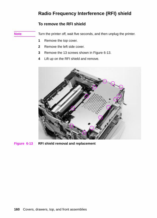
Radio Frequency Interference (RFI) shield
To remove the RFI shield
Note Turn the printer off, wait five seconds, and then unplug the printer.
1 Remove the top cover.
2 Remove the left side cover.
3 Remove the 13 screws shown in Figure 6-13.
4 Lift up on the RFI shield and remove.
Figure 6-13 RFI shield removal and replacement
160 Covers, drawers, top, and front assemblies

Laser/scanner assembly
To remove the laser/scanner assembly
Note Turn the printer off, wait five seconds, and then unplug the printer.
1 Remove the top cover.
2 Remove the left side cover.
3 Remove the RFI shield.
4 Disconnect the cable from the laser/scanner to the DC controller (J1006 on the DC controller). See callout 1, Figure 7-31 on page 347.
5 Free the cable harness from the two cable stays shown below in callout 1.
6 Disconnect the flat ribbon cable and the other cable from the laser/scanner PCB.
7 Remove the four long brass screws shown in callout 2.
8 Tilt the narrow end of the laser/scanner assembly up, pull it toward you, and lift slightly to remove it.
Figure 6-14 Laser/scanner assembly removal and replacement
1
2
Chapter 6 Removal and replacement 161

DC controller
To remove the DC controller
Note Turn the printer off, wait five seconds, and then unplug the printer.
1 Remove the top cover.
2 Remove the left side cover.
3 Remove the RFI shield.
4 Disconnect all connectors from the DC controller, including the two ribbon cables.
5 Remove the five screws from the DC controller shown in Figure 6-15.
6 Lift the DC controller up and out to remove.
DC controller replacement tip
The connectors are keyed and will fit in only one slot.
Figure 6-15 DC controller removal and replacement
162 Covers, drawers, top, and front assemblies

Developing PCB
To remove the developing PCB
Note Turn the printer off, wait five seconds, and then unplug the printer.
1 Remove the top cover.
2 Remove the left side cover.
3 Remove the RFI shield.
4 Remove the plastic shield (callout 1, Figure 6-16) by releasing the two tabs shown (callout 2, Figure 6-16). If necessary, insert a flatblade screwdriver between the shield and the frame to release the tab.
5 Lift up on the shield to remove it.
Figure 6-16 Developing PCB removal and replacement (1 of 2)
6 Disconnect the connectors from the developing PCB and release the cables from the metal cable stay (callout 2, Figure 6-17 on page 164).
7 Remove the five or four screws (depending on the version of printer that is being serviced) from the developing PCB (callout 1, Figure 6-17 on page 164).
8 Lift the developing PCB up and out.
1
2
Chapter 6 Removal and replacement 163

Reinstallation tip
When securing the developing PCB with the five or four screws, secure the metal cable stay (callout 2, Figure 6-17) at the location shown.
Figure 6-17 Developing PCB removal and replacement (2 of 2)
1
2
164 Covers, drawers, top, and front assemblies

Top cover switch assembly
Note Turn the printer off, wait five seconds, and then unplug the printer.
Two versions of the HP Color LaserJet 4500 series printers are available. To identify which printer version you are servicing, see page 146.
To remove the top cover switch assembly
1 Remove the top cover.
2 Remove the left side cover.
3 Remove the RFI shield.
4 Disconnect the sensor and switch cables from the top cover switch assembly (callout 1, Figure 6-18 on page 166).
5 Follow the instructions below, depending on the version of printer that is being serviced.
For printer serial numbers xx G or lower:
6 Free the sensor and switch cables from their cable stays.
7 Remove the two screws from the top cover switch assembly (callout 2, Figure 6-18 on page 166).
8 Slide the switch assembly to the left side of the printer, and then lift it up and out.
For printer serial numbers xx H or higher:
6 Open the drum drawer (top drawer) until it stops and remove the imaging drum, protecting it from light.
CAUTION Exposure to light for more than 15 seconds can seriously damage the imaging drum.
7 Free the cables from the five cable stays (callout 3, Figure 6-18 on page 166).
8 Remove the two screws that secure the switch assembly and lower cable guide to the printer frame (callout 1, Figure 6-19 on page 167).
9 Pull the rear door switch arm toward the front of the printer while lifting the switch assembly up and out slightly, taking care not to damage the cable guide.
Chapter 6 Removal and replacement 165
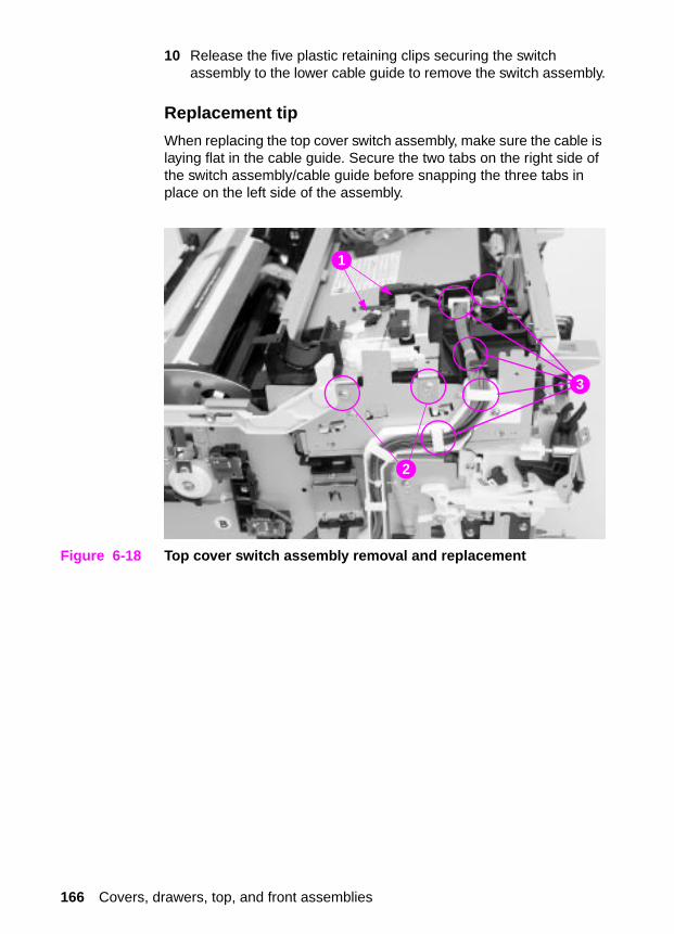
10 Release the five plastic retaining clips securing the switch assembly to the lower cable guide to remove the switch assembly.
Replacement tip
When replacing the top cover switch assembly, make sure the cable is laying flat in the cable guide. Secure the two tabs on the right side of the switch assembly/cable guide before snapping the three tabs in place on the left side of the assembly.
Figure 6-18 Top cover switch assembly removal and replacement
2
1
3
166 Covers, drawers, top, and front assemblies

Figure 6-19 Top cover switch assembly removal and replacement
1
Chapter 6 Removal and replacement 167
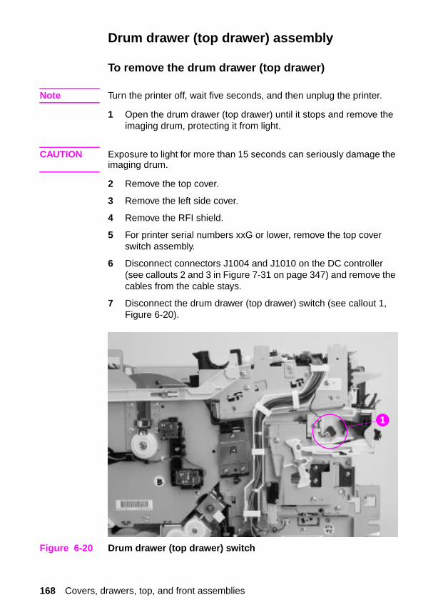
Drum drawer (top drawer) assembly
To remove the drum drawer (top drawer)
Note Turn the printer off, wait five seconds, and then unplug the printer.
1 Open the drum drawer (top drawer) until it stops and remove the imaging drum, protecting it from light.
CAUTION Exposure to light for more than 15 seconds can seriously damage the imaging drum.
2 Remove the top cover.
3 Remove the left side cover.
4 Remove the RFI shield.
5 For printer serial numbers xxG or lower, remove the top cover switch assembly.
6 Disconnect connectors J1004 and J1010 on the DC controller (see callouts 2 and 3 in Figure 7-31 on page 347) and remove the cables from the cable stays.
7 Disconnect the drum drawer (top drawer) switch (see callout 1, Figure 6-20).
Figure 6-20 Drum drawer (top drawer) switch
1
168 Covers, drawers, top, and front assemblies

8 Free the main cable from all cable stays at the top and left side of the printer; push the cables back toward the rear of the printer.
9 Remove the two screws from the black plastic housing shown in callout 1, Figure 6-21.
10 Lift the black plastic housing and slide it forward onto the front drawer.
Figure 6-21 Drum drawer (top drawer) assembly removal and replacement (1 of 3)
11 Slide a small flat-blade screwdriver under the black plastic retaining clips on the drawer guide rails. Then lift the tab and pull the drawer out slightly to clear the latch that holds the plastic retaining clips in place (see Figure 6-22 and Figure 6-23).
12 Pull the drum drawer (top drawer) straight out and away from the printer.
Reinstallation tip
When replacing the drum drawer (top drawer) assembly, make sure the cable is laying flat in the cable guide.
1
Chapter 6 Removal and replacement 169
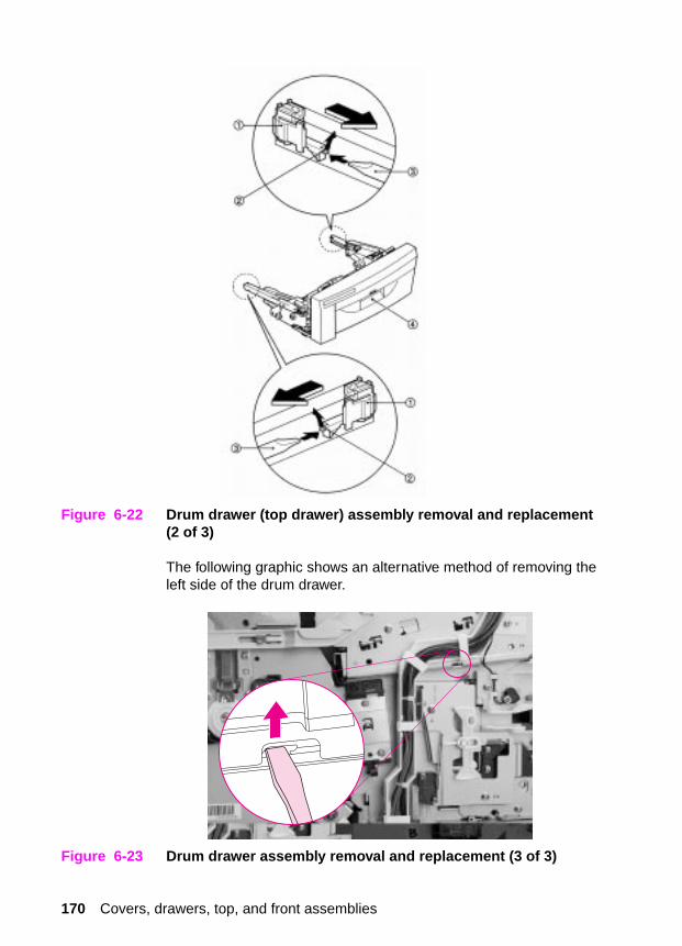
Figure 6-22 Drum drawer (top drawer) assembly removal and replacement (2 of 3)
The following graphic shows an alternative method of removing the left side of the drum drawer.
Figure 6-23 Drum drawer assembly removal and replacement (3 of 3)
170 Covers, drawers, top, and front assemblies
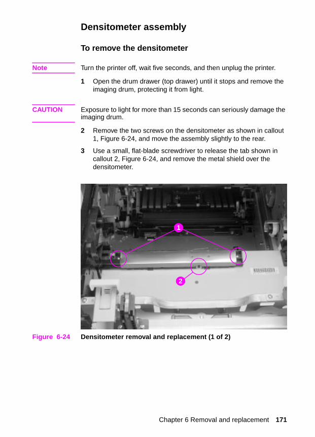
Densitometer assembly
To remove the densitometer
Note Turn the printer off, wait five seconds, and then unplug the printer.
1 Open the drum drawer (top drawer) until it stops and remove the imaging drum, protecting it from light.
CAUTION Exposure to light for more than 15 seconds can seriously damage the imaging drum.
2 Remove the two screws on the densitometer as shown in callout 1, Figure 6-24, and move the assembly slightly to the rear.
3 Use a small, flat-blade screwdriver to release the tab shown in callout 2, Figure 6-24, and remove the metal shield over the densitometer.
Figure 6-24 Densitometer removal and replacement (1 of 2)
1
2
Chapter 6 Removal and replacement 171

4 Remove the plastic cable cover as shown in Figure 6-25.
5 Remove the cable from the cable stays, and then disconnect the connector from the densitometer.
6 Remove the densitometer by sliding it toward the rear of the printer.
Figure 6-25 Densitometer removal and replacement (2 of 2)
172 Covers, drawers, top, and front assemblies

Right side assemblies
Formatter
To remove the formatter
1 Turn off the printer.
2 When the fans are turned off, unplug the printer.
CAUTION Power is applied to the formatter as long as the printer is plugged-in. Removing the formatter while power is supplied to the printer may damage the formatter.
3 Remove the six screws in the formatter shown in Figure 6-26.
4 Slide the formatter out of the rear of the printer.
Figure 6-26 Formatter removal and replacement
Chapter 6 Removal and replacement 173

Formatter PCB
To remove the formatter PCB from the cradle
Note Turn the printer off, wait five seconds, and then unplug the printer.
Before replacing the formatter or firmware, make sure to record the printer’s serial number, fuser maintenance count, transfer maintenance count, color page count, and total page count.
1 Remove the formatter from the printer by removing the six screws.
2 Remove the EIO cards (if any) from the EIO slots.
3 Disconnect the L-shaped (I/O) card from the formatter by lifting up on the narrow end of the PCB.
4 While lifting the two black plastic tabs located over the EIO connectors on the formatter PCB, slide the formatter PCB out of the cradle.
Note Lift the narrow end of the L-shaped (I/O) card so the connectors have clearance.
5 Install the new formatter PCB by sliding it into the cradle.
6 Reconnect the L-shaped (I/O) card to the formatter PCB.
7 Pull all DIMMs from the old formatter PCB and install them on the new formatter PCB, making sure the firmware DIMM is installed in the ROM ONLY DIMM slot.
8 Install the EIO cards (if any).
9 Install the formatter back into the printer.
10 Power up the printer in NVRAM initialization mode as follows:
Step 1 Hold down both the [Cancel Job] and [Select] keys until all the LED lights are on, then release the keys.
Step 2 Press [Cancel Job].
Step 3 Press [Select].
11 Once initialization is complete, turn off the printer, then turn it back on in service mode (see chapter 7, “Service mode” for more information).
12 Enter the printer’s serial number, fuser maintenance count, transfer maintenance count, color page count, and total page count.
13 Print a configuration page to verify printer operation.
174 Right side assemblies

Formatter pan assembly
To remove the formatter pan assembly
Note Turn the printer off, wait five seconds, and then unplug the printer.
1 Open the drum drawer (top drawer) until it stops and remove the imaging drum, protecting it from light.
CAUTION Exposure to light for more than 15 seconds can seriously damage the imaging drum.
2 Open the ITB drawer (middle drawer) and tray 2.
3 Remove the top cover.
4 Remove the right side cover.
5 Remove the right rear cover.
6 Remove the left side cover.
7 Remove the RFI shield.
8 Remove the control panel.
9 Remove the front right cover.
10 Remove the two screws for the connector cover shown in Figure 6-27.
Figure 6-27 Formatter pan assembly removal and replacement (1 of 4)
Chapter 6 Removal and replacement 175
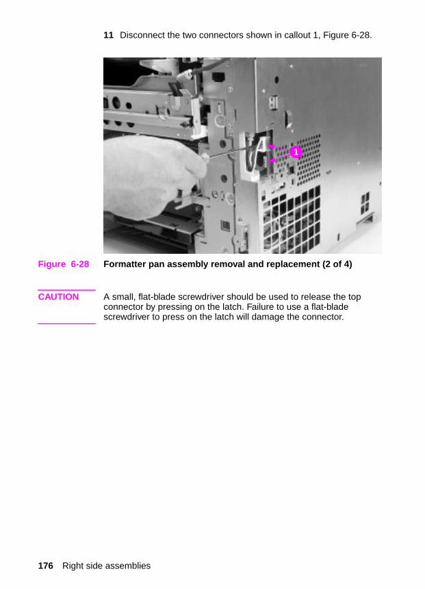
11 Disconnect the two connectors shown in callout 1, Figure 6-28.
Figure 6-28 Formatter pan assembly removal and replacement (2 of 4)
CAUTION A small, flat-blade screwdriver should be used to release the top connector by pressing on the latch. Failure to use a flat-blade screwdriver to press on the latch will damage the connector.
1
176 Right side assemblies

12 Disconnect the ribbon cable from the DC controller shown in callout 1, Figure 6-29.
Figure 6-29 Formatter pan assembly removal and replacement (3 of 4)
Note Although Figure 6-29 depicts the RFI shield still installed, make sure this shield was removed at step 7.
13 Remove the control panel cable from its cable stay, if necessary.
14 Remove the screws from the formatter pan assembly (shown in Figure 6-29 and Figure 6-30).
1
Chapter 6 Removal and replacement 177
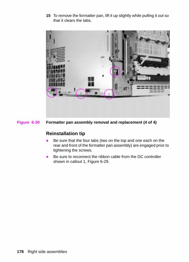
15 To remove the formatter pan, lift it up slightly while pulling it out so that it clears the tabs.
Figure 6-30 Formatter pan assembly removal and replacement (4 of 4)
Reinstallation tip� Be sure that the four tabs (two on the top and one each on the
rear and front of the formatter pan assembly) are engaged prior to tightening the screws.
� Be sure to reconnect the ribbon cable from the DC controller shown in callout 1, Figure 6-29.
178 Right side assemblies

Power supply
To remove the power supply
Note Turn the printer off, wait five seconds, and then unplug the printer.
Two versions of the HP Color LaserJet 4500 series printers are available. To identify which printer version you are servicing, see page 146.
1 Remove the formatter pan assembly.
2 Disconnect the four connectors (three in front and one in top rear of printer) from the power supply.
3 Free the cable harness from the cable stay.
4 Remove the five or eight screws (depending on the version of printer you are working on) from the power supply shown in Figure 6-31.
5 Slide the power supply forward slightly to clear the rear retaining tab and tilt the top of the assembly out. Lift the power supply up and out.
Figure 6-31 Power supply removal and replacement
Chapter 6 Removal and replacement 179

High-voltage power supply
To remove the high-voltage power supply (HVPS)
Note Turn the printer off, wait five seconds, and then unplug the printer.
Two versions of the HP Color LaserJet 4500 series printers are available. To identify which printer version you are servicing, see page 146.
1 Remove the formatter pan assembly.
2 Remove the power supply.
Note Some printers have a cover over the high-voltage power supply.
3 Remove the rear door.
4 Remove the fusing assembly.
5 Disconnect the four cables from their connectors (callout 1, Figure 6-32 or callout 1, Figure 6-33, depending on the version of printer being serviced).
6 Free the cable harness from the cable stays.
7 Remove the four brass screws shown in callout 2, Figure 6-32 from the HVPS.
8 Carefully pull the HVPS out. Ensure that the rear plastic retaining strap attached to the HVPS clears the chassis and its remaining components.
High-voltage power supply replacement tip
When reinstalling the HVPS, carefully insert the plastic retaining strap attached to the rear of the HVPS through the chassis.
180 Right side assemblies

Figure 6-32 High- volt age power supp ly rem oval and replacement (n ewer version printe rs)
Figure 6-33 High- volt age power supp ly rem oval and replacement (older version printe rs)
2 1
1
Chapter 6 Removal and replacement 181

Drum drive assembly
To remove the drum drive assembly
Note Turn the printer off, wait five seconds, and then unplug the printer.
1 Open both front drawers.
CAUTION Make sure the imaging drum is protected from light. Exposure to light for more than 15 seconds can seriously damage the imaging drum.
2 Remove the formatter pan assembly.
3 Remove the power supply.
4 Disconnect the two cables from the HVPS and free them from the cable stay.
5 Remove the screw that secures the cable trough to the drum drive assembly as shown in Figure 6-34.
Figure 6-34 Drum drive assembly removal and replacement (1 of 3)
6 Carefully release the cable trough by pulling out slightly on the bottom and releasing the clip. Depress the plastic v-shaped clip underneath the DC controller to loosen the cable guide. Slide the trough toward the rear of the printer until it is free.
182 Right side assemblies

7 Disconnect J204 on the developing PCB and free it from its cable stay.
8 Remove the eight black screws from the drum drive assembly shown in Figures 6-35 and 6-36.
9 Gently slide the drum drive assembly straight out from the printer assembly taking care not to damage the cable.
Figure 6-35 Drum drive assembly removal and replacement (2 of 3)
Chapter 6 Removal and replacement 183

Figure 6-36 Drum drive assembly removal and replacement (3 of 3)
184 Right side assemblies
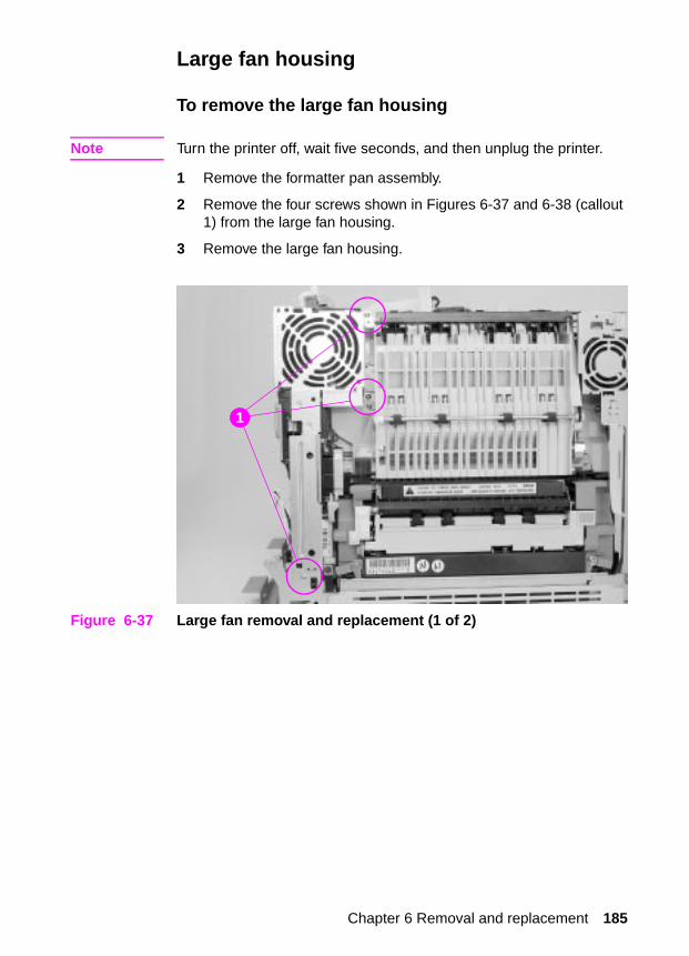
Large fan housing
To remove the large fan housing
Note Turn the printer off, wait five seconds, and then unplug the printer.
1 Remove the formatter pan assembly.
2 Remove the four screws shown in Figures 6-37 and 6-38 (callout 1) from the large fan housing.
3 Remove the large fan housing.
Figure 6-37 Large fan removal and replacement (1 of 2)
1
Chapter 6 Removal and replacement 185
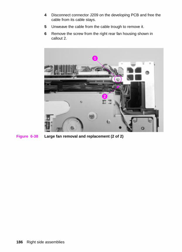
4 Disconnect connector J209 on the developing PCB and free the cable from its cable stays.
5 Unweave the cable from the cable trough to remove it.
6 Remove the screw from the right rear fan housing shown in callout 2.
Figure 6-38 Large fan removal and replacement (2 of 2)
1
2
186 Right side assemblies

Carousel drive assembly
To remove the carousel drive assembly
Note Turn the printer off, wait five seconds, and then unplug the printer.
1 Remove the formatter pan assembly.
2 Remove the rear door.
3 Remove the large fan housing.
4 Free the cables from the rear cable trough located beneath the large fan housing shown in callout 1.
5 Disconnect the two motor cables from their connectors (J203 and J205) located on the developing PCB and remove them from their trough.
6 Disconnect the sensor as shown in callout 2.
7 Disconnect the two high-voltage (red) cables from the HVPS and free the front cable from the cable stays.
8 Push up and out on the cable trough shown in callout 3 to release the lower tabs. Then tilt the bottom of the cable trough out slightly to gain access to the top screws on the carousel drive assembly.
Note To remove the cable trough, you may need to first loosen the screw on top of the developing PCB housing.
Figure 6-39 Carousel drive assembly removal and replacement (1 of 2)
2
3
1
Chapter 6 Removal and replacement 187
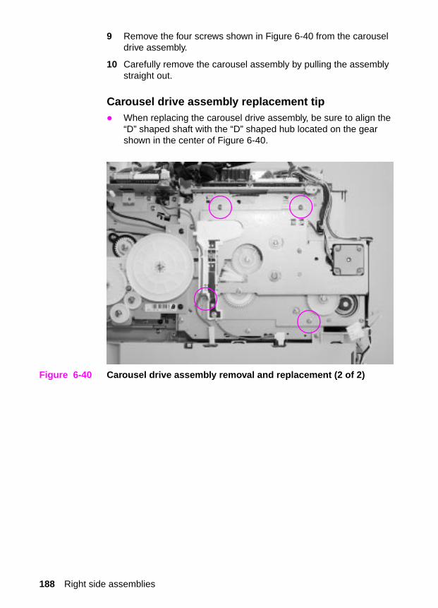
9 Remove the four screws shown in Figure 6-40 from the carousel drive assembly.
10 Carefully remove the carousel assembly by pulling the assembly straight out.
Carousel drive assembly replacement tip� When replacing the carousel drive assembly, be sure to align the
“D” shaped shaft with the “D” shaped hub located on the gear shown in the center of Figure 6-40.
Figure 6-40 Carousel drive assembly removal and replacement (2 of 2)
188 Right side assemblies

Paper size switch PCB
To remove the paper size switch PCB
Note Turn the printer off, wait five seconds, and then unplug the printer.
1 Pull tray 2 out.
2 Remove the high-voltage power supply.
3 Disconnect the connector as shown in callout 1.
4 Remove the black screw from the paper size switch PCB shown in callout 2. Remove the switch PCB.
Figure 6-41 Paper size switch removal and replacement
12
Chapter 6 Removal and replacement 189

Left side assemblies
Drawer switch assembly
To remove the drawer switch assembly
1 Remove the top cover.
2 Remove the left side cover.
3 Disconnect the connector shown in callout 1.
4 Remove the two screws from the drawer switch assembly shown in callout 2.
5 Pull the drawer switch assembly away from the chassis.
Replacement tip� Open both front drawers for easier installation.
Figure 6-42 Switch plate assembly removal and replacement
2
1
190 Left side assemblies

Paper feed PCB
To remove the paper feed PCB
Note Turn the printer off, wait five seconds, and then unplug the printer.
1 Remove the top cover.
2 Remove the left side cover.
3 Remove the rear door.
4 Remove the fusing assembly.
5 Disconnect the small fan connector shown in callout 1.
Figure 6-43 Paper feed PCB removal and replacement (1 of 3)
2
1
2 3
Chapter 6 Removal and replacement 191

6 Remove the three screws from the left rear sheet metal fan shield shown in Figure 6-43 and Figure 6-44 (callout 2) and remove the shield.
Figure 6-44 Paper feed PCB removal and replacement (2 of 3)
7 Remove the screw in the black plastic cover shown in callout 3, Figure 6-43.
8 Remove the black plastic cover.
2
192 Left side assemblies

9 Remove the eight cables from their connectors on the paper feed PCB shown in Figure 6-45.
10 Remove the screw from the rear of the paper feed PCB (callout 4, Figure 6-45).
11 Carefully remove the paper feed PCB by sliding the board backwards, then tilt the top of the board forward to clear the top of the board from the metal tab along the top of the PCB.
Paper feed PCB replacement tip� Carefully insert the paper feed PCB into the chassis ensuring that
the two paper feed PCB metal tabs sit in the open tab holders in the chassis.
Figure 6-45 Paper feed PCB removal and replacement (3 of 3)
4
Chapter 6 Removal and replacement 193
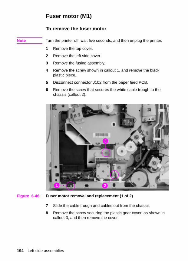
Fuser motor (M1)
To remove the fuser motor
Note Turn the printer off, wait five seconds, and then unplug the printer.
1 Remove the top cover.
2 Remove the left side cover.
3 Remove the fusing assembly.
4 Remove the screw shown in callout 1, and remove the black plastic piece.
5 Disconnect connector J102 from the paper feed PCB.
6 Remove the screw that secures the white cable trough to the chassis (callout 2).
Figure 6-46 Fuser motor removal and replacement (1 of 2)
7 Slide the cable trough and cables out from the chassis.
8 Remove the screw securing the plastic gear cover, as shown in callout 3, and then remove the cover.
21
3
194 Left side assemblies

9 Remove the three fuser motor screws shown in Figure 6-47.
10 Carefully pull to remove the fuser motor and free the cable from the cable trough.
Figure 6-47 Fuser motor removal and replacement (2 of 2)
Chapter 6 Removal and replacement 195
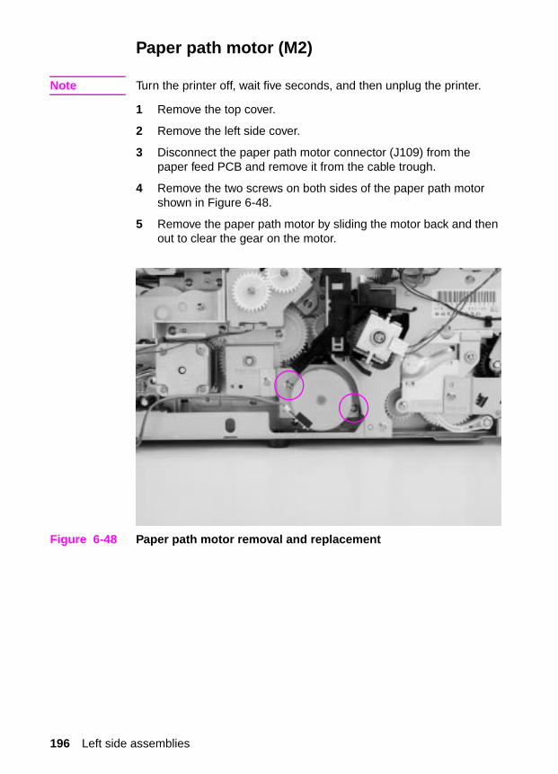
Paper path motor (M2)
Note Turn the printer off, wait five seconds, and then unplug the printer.
1 Remove the top cover.
2 Remove the left side cover.
3 Disconnect the paper path motor connector (J109) from the paper feed PCB and remove it from the cable trough.
4 Remove the two screws on both sides of the paper path motor shown in Figure 6-48.
5 Remove the paper path motor by sliding the motor back and then out to clear the gear on the motor.
Figure 6-48 Paper path motor removal and replacement
196 Left side assemblies

Paper pick solenoid (SL2)
To remove the paper pick solenoid
1 Remove the top cover.
2 Remove the left side cover.
3 Disconnect the solenoid connector (J106) from the paper feed PCB, and free the cable from the cable stays. Note the cable path when removing the cable.
4 Remove the screw (callout 1) and e-clip (callout 2) that hold the solenoid assembly in place, and then remove the solenoid assembly. For printers with serial numbers xxH or higher, also remove the screw shown in callout 3 to remove the solenoid assembly.
Replacement tip
CAUTION When reinstalling the solenoid assembly, make sure that the flat parts of the tray 2 pickup rollers are down and that the plastic spring-loaded gear is fully engaged.
Figure 6-49 Paper pick solenoid removal and replacement
1 23
Chapter 6 Removal and replacement 197
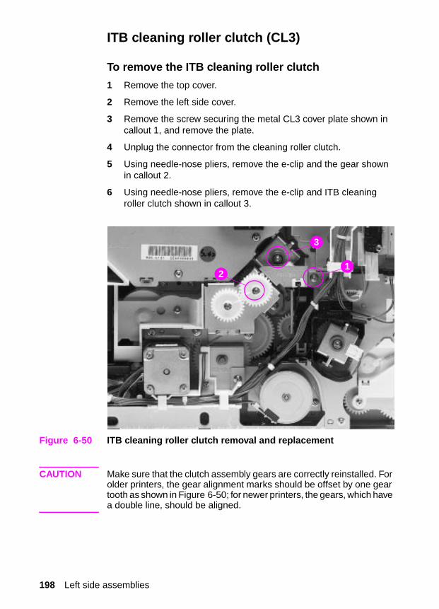
ITB cleaning roller clutch (CL3)
To remove the ITB cleaning roller clutch
1 Remove the top cover.
2 Remove the left side cover.
3 Remove the screw securing the metal CL3 cover plate shown in callout 1, and remove the plate.
4 Unplug the connector from the cleaning roller clutch.
5 Using needle-nose pliers, remove the e-clip and the gear shown in callout 2.
6 Using needle-nose pliers, remove the e-clip and ITB cleaning roller clutch shown in callout 3.
Figure 6-50 ITB cleaning roller clutch removal and replacement
CAUTION Make sure that the clutch assembly gears are correctly reinstalled. For older printers, the gear alignment marks should be offset by one gear tooth as shown in Figure 6-50; for newer printers, the gears, which have a double line, should be aligned.
2
3
1
198 Left side assemblies
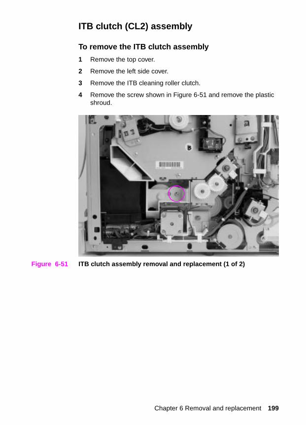
ITB clutch (CL2) assembly
To remove the ITB clutch assembly
1 Remove the top cover.
2 Remove the left side cover.
3 Remove the ITB cleaning roller clutch.
4 Remove the screw shown in Figure 6-51 and remove the plastic shroud.
Figure 6-51 ITB clutch assembly removal and replacement (1 of 2)
Chapter 6 Removal and replacement 199

5 Disconnect the cable from the clutch assembly.
6 Remove the three screws shown in Figure 6-52 and remove the clutch assembly.
Figure 6-52 ITB clutch assembly removal and replacement (2 of 2)
CAUTION Make sure that the clutch assembly gears are correctly reinstalled. For older printers, the gear alignment marks should be offset by one gear tooth as shown in Figure 6-50; for newer printers, the cams, which have a double line, should be aligned.
For proper operation, ensure that the ITB clutch (CL2) is connected to J103 on the Paper Feed PCB and that the ITB cleaning roller clutch (CL3) is connected to J104.
200 Left side assemblies

Transfer roller cam clutch (CL4)
To remove the transfer cam clutch
1 Remove the top cover.
2 Remove the left side cover.
3 Disconnect the connector (J105 at the Paper Feed PCB) from the clutch.
4 Remove the e-clip shown in Figure 6-53 with needle-nose pliers and remove the clutch.
Figure 6-53 Transfer roller cam clutch removal and replacement
Replacement tip
For proper operation, ensure that the cable is connected to J105 on the paper feed PCB.
Chapter 6 Removal and replacement 201

Left side gears
To remove the left side gears
1 Remove the top cover.
2 Remove the left side cover.
3 Remove the fusing assembly.
4 Remove the screw shown in callout 1, Figure 6-46 on page 194 and remove the black plastic piece.
5 Disconnect all connectors from the paper feed PCB and free the cables from the cable stays.
6 Remove the screw securing the gear cover and remove the cover shown in callout 3, Figure 6-46 on page 194.
7 Remove the fuser motor.
8 Remove the paper path motor.
9 Remove the three clutches: CL2, CL3, and CL4.
10 Remove the four screws (callout 1, Figure 6-54 on page 203) and remove the sheet metal over the gears.
11 Remove the one or two screws (shown in callout 2, Figure 6-54 on page 203) and e-clip (shown in callout 3, Figure 6-54 on page 203) that hold the solenoid assembly in place and then remove the solenoid assembly.
12 Remove any e-clips or bushings necessary to remove the affected gears.
Left side gear replacement
1 Install the back half of the large double gear shown in callout 1, Figure 6-55 with the small portion of the gear (18T) facing outward.
2 Install the two gears (shown in callout 2, Figure 6-55 on page 203) so they cover the back half of the large double gear.
3 Install the remaining gears and the front half of the large double gear so they appear as shown in Figure 6-55 on page 203.
CAUTION When reinstalling the solenoid assembly, make sure that the flat parts of the pickup rollers are down and that the plastic spring-loaded gear is fully engaged.
202 Left side assemblies

Figure 6-54 Left side gears removal and replacement (1 of 2)
Figure 6-55 Left side gears removal and replacement (2 of 2)
2
3
1
1
2
Chapter 6 Removal and replacement 203

Rear assemblies
Large right side fan
To remove the large right side fan
1 Remove the formatter pan assembly.
2 Remove the four screws as shown in Figures 6-56 and 6-57, and remove the fan shield.
3 Disconnect the fan cable (J209) from the developing PCB.
4 Unweave the fan cable from the cable stays.
5 Release the plastic tabs at the top and bottom of the fan housing, and then slide the fan out.
Large right side fan replacement tip� Ensure that the fan cable is facing out and located in the lower
corner.
Figure 6-56 Large right side fan removal and replacement (1 of 2)
204 Rear assemblies

Figure 6-57 Large right side fan removal and replacement (2 of 2)
Chapter 6 Removal and replacement 205

Left side fan
To remove the left side fan
1 Remove the top cover.
2 Remove the left side cover.
3 Remove the rear door.
4 Disconnect the cable shown in callout 1, Figure 6-58.
5 Remove the three screws from the left rear fan shield shown in Figures 6-58 and 6-59 (callout 2) and remove the fan shield.
6 Disconnect the cable shown in callout 1, Figure 6-60.
7 Remove the screw from the black plastic cover and remove the fan casing shown in callout 2,Figure 6-60.
8 Free the fan cable from the cable stay.
9 Press out on the three plastic tabs and slide the fan out.
Left side fan replacement tip
Make sure the label is facing out when replacing the left-side fan.
Figure 6-58 Left side fan removal and replacement (1 of 3)
1
2
2
206 Rear assemblies

Figure 6-59 Left side fan removal and replacement (2 of 3)
Figure 6-60 Left side fan removal and replacement (3 of 3)
2
1
2
Chapter 6 Removal and replacement 207

Face-down assembly
To remove the face-down assembly
1 Remove the top cover.
2 Remove the left side cover.
3 Remove the rear door.
4 Remove the left side fan.
5 Disconnect the bin full sensor shown in callout 1, Figure 6-61, and free the cable from the cable stay.
6 Remove the three screws from the face-down assembly shown in callouts 2 and 3, Figure 6-61.
7 With your right hand, lift up slightly on the assembly to release the tab. Then, pull the assembly out with your right hand while pushing the assembly to your right to release the plastic tab on your left.
Replacement tip
Note the position of the black shoulder screw and metal bracket shown in callout 3, Figure 6-61.
Figure 6-61 Rear paper path assembly removal and replacement
1
23
208 Rear assemblies

Internal assemblies
Carousel housing assembly
To remove the carousel housing assembly
1 Remove the toner cartridges from the carousel.
2 Remove the RFI shield.
3 Remove the formatter pan assembly.
4 Remove the rear door.
5 Remove the fusing assembly.
6 Remove the toner catch tray by pushing down on the clip in the middle of the tray as shown in callout 1, Figure 6-66, and then pull the tray out.
Figure 6-62 Carousel housing assembly removal and replacement (1 of 4)
7 Remove the carousel drive assembly.
8 Detach the cable guide just beneath the developing PCB by pushing up and out on the cable trough (Figure 6-57 on page 205) to release the lower tabs. Then push down to release the upper tabs.
Chapter 6 Removal and replacement 209

9 Detach all cables from the developing PCB and remove them from the cable stays and cable guide.
10 Remove the screw from the carousel brake assembly shown in Figure 6-62 and remove the brake assembly.
11 Remove the power supply.
12 Remove the HVPS.
13 Remove the left side fan assembly.
14 Open the drum drawer (top drawer) half way.
15 Open the drum drawer (top drawer) and remove the imaging drum, protecting it from light.
CAUTION Exposure to light for more than 15 seconds can seriously damage the imaging drum.
16 Close the drum drawer half way.
17 Remove the three brass screws shown in Figure 6-63. Release the two black tabs and pull out the drum ground plate.
18 Remove the two screws shown in Figure 6-64.
19 Remove the four screws shown in Figure 6-65.
WARNING! Use caution when removing the carousel assembly. The printer will tip forward if both the drum drawer (top drawer) and the ITB (middle drawer) are both fully open.
20 Working from the back of the printer, slide the carousel housing assembly toward your right, and then lift up and out.
210 Internal assemblies
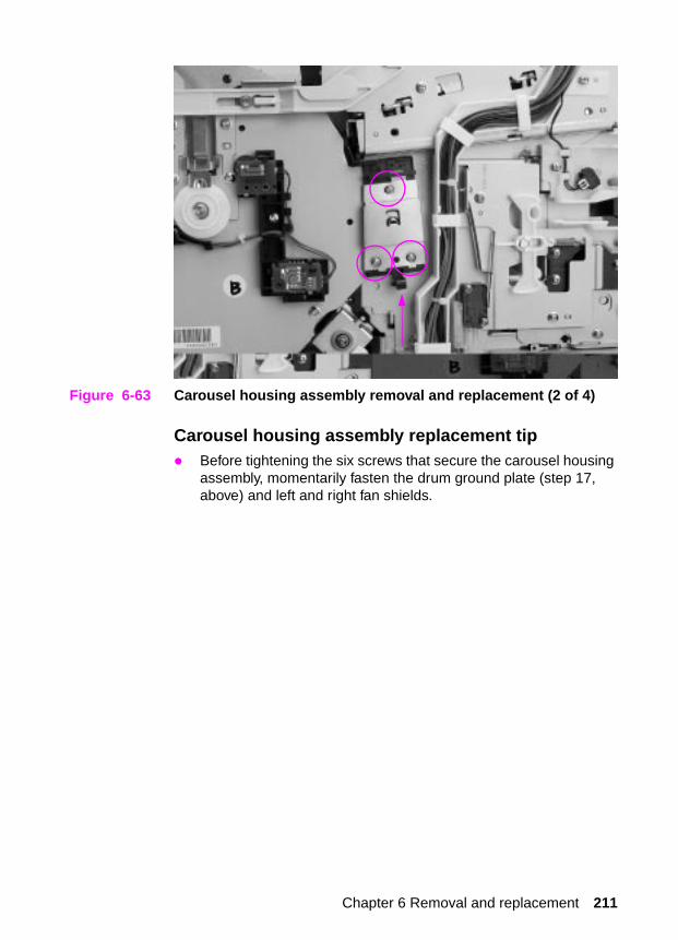
Figure 6-63 Carousel housing assembly removal and replacement (2 of 4)
Carousel housing assembly replacement tip� Before tightening the six screws that secure the carousel housing
assembly, momentarily fasten the drum ground plate (step 17, above) and left and right fan shields.
Chapter 6 Removal and replacement 211

Figure 6-64 Carousel housing assembly removal and replacement (left side view when facing printer) (3 of 4)
Figure 6-65 Carousel housing assembly removal and replacement (right side view when facing printer) (4 of 4)
212 Internal assemblies

Paper transport assembly
To remove the paper transport assembly
1 Remove the fusing assembly.
2 Remove the toner catch tray by pushing down on the clip in the middle and sliding it straight out as shown in callout 1, Figure 6-66.
3 Remove the screw from the rear of the assembly (callout 2).
4 Slide the paper transport assembly toward your left until it stops. Tilt the assembly up to clear the drive shaft coupler on your right and carefully work the assembly out of the printer.
Paper transport assembly replacement tip� Make sure that all tabs are under the metal slots (two on the right,
one on the left) and that the drive shaft coupler engages properly.
Figure 6-66 Paper transport assembly removal and replacement
1
2
Chapter 6 Removal and replacement 213

Paper pick rollers
To remove the paper pick rollers
1 Remove tray 2. Then, follow the instructions provided below, depending on the version of printer.
For printer serial numbers xx G or lower (The paper pick roller shaft is held in place with two white plastic clips.)
2 Pull the paper pick roller shaft down until it releases from the two plastic clips shown in callout 1, Figure 6-67.
For printer serial numbers xx H or higher (The paper pick roller shaft is held in place with two black plastic clips.)
2 Do not remove the roller shaft unless you have to replace it. To replace the individual pick rollers, rotate the shaft by hand so that the flat parts of the D-shaped rollers are facing up. Grasping the center of the D-shaped roller with one hand, press down on the roller clip on the flat portion of the roller with the other hand and pull it off of the shaft. If you need to remove the entire shaft, insert a small flat-blade screwdriver into both of the plastic clips (as shown in callout 2, Figure 6-67) to remove the roller.
Figure 6-67 Paper pick rollers removal and replacement
2 1
214 Internal assemblies
Paper pick roller replacement tip
When reinstalling the roller shaft, make sure that the flat parts of the D-shaped rollers are facing down.
Chapter 6 Removal and replacement 215