recent progress in dna origami - california institute of …pwkr/dna-nanotech-reviews/201… ·...
TRANSCRIPT

UNIT 12.8Recent Progress in DNA OrigamiTechnology
Masayuki Endo1 and Hiroshi Sugiyama1,2
1Institute for Integrated Cell-Material Sciences (iCeMS), Kyoto University, Kyoto, Japan2Department of Chemistry, Graduate School of Science, Kyoto University, Kyoto, Japan
ABSTRACT
DNA origami is an emerging technology for designing defined two-dimensional DNA nano-structures. In this review, we focus on and describe several types of DNA origami-related stud-ies, as follows: (1) programmed DNA origami assembly, (2) DNA origami-templated molecularassembly, (3) design and construction of various three-dimensional DNA origami structures,(4) programmed functionalization of DNA origami and combination with top-down nanotechnol-ogy, (5) single molecular observation on a designed DNA origami, and (6) DNA nanomachinesworking on a DNA origami. Curr. Protoc. Nucleic Acid Chem. 45:12.8.1-12.8.19. C© 2011 byJohn Wiley & Sons, Inc.
Keywords: DNA origami � designed nanospace � single molecular analysis �
DNA nanomachine � high-speed AFM
INTRODUCTIONRecent progress in DNA nanotechnology
allows the expansion of the practical designof various nanoscale structures and the appli-cation for the production of complicated mate-rials (Seeman, 2003; Feldkamp and Niemeyer,2006; Endo and Sugiyama, 2009). The field ofDNA nanotechnology was pioneered by NedSeeman, who created the various importantDNA motifs and strategies for self-assemblythat constitute the basics of structural DNAnanotechnology (Seeman, 2003). DNA nan-otechnology, now applied for the constructionof nanoscale structures and functionalized ma-terials, is further utilized in molecular mechan-ics, computation, imaging, synthetic chemistryand biochemical analysis, and continues todevelop in response to technology demands(Seeman, 2003; Feldkamp and Niemeyer,2006; Endo and Sugiyama, 2009). “DNAorigami,” a new DNA self-assembly systembased on well-established DNA nanotechnol-ogy, enables the design of two-dimensional(2D) nanostructures in a wide variety ofshapes with a defined size. Moreover, selectivepositioning of the functional molecules andnanoparticles onto the designed DNA nanos-tructures has been achieved, which shows thecapacity of the DNA origami system to in-stall the desired components into the nanoscalespace by programmed self-assembly.
Here, we highlight the latest research re-lated to DNA origami-based DNA nanotech-
nology, and describe the expansion of the DNAorigami method and its contribution to nan-otechnology. We focus on the design and con-struction of various 2D and 3D structures, theirfunctionalizations, and programmed arrange-ments, and describe the application for obser-vation of the movement of single biomoleculesand molecular machines on the designed DNAorigami scaffold.
TWO-DIMENSIONAL DNAORIGAMI
DNA origami, developed by Rothemundin 2006 (Rothemund, 2006), has enabled theconstruction of a wide variety of 2D struc-tures of ∼100 nm in size, including rectan-gles, triangles, and even a smiley face andfive-pointed star (Fig. 12.8.1). In this method,a long single-stranded DNA (M13mp18: 7249nucleotides) and the sequence-designed com-plementary strands (called “staple strands;”most of them are 32mer) are mixed and thenannealed from 95◦C to room temperature over2 hr, resulting in the formation of target struc-tures by self-assembly (Fig. 12.8.1A). Thestructure can be imaged by atomic force mi-croscopy (AFM), and the assembled struc-ture formed according to a design. To cre-ate 2D DNA origami structures, the adjacentdouble-stranded DNAs (dsDNA) should beconnected to each other via the crossover. Inthis design, the geometry of the double he-lices involved has a three-helical rotation in
Current Protocols in Nucleic Acid Chemistry 12.8.1-12.8.19, June 2011Published online June 2011 in Wiley Online Library (wileyonlinelibrary.com).DOI: 10.1002/0471142700.nc1208s45Copyright C© 2011 John Wiley & Sons, Inc.
NucleicAcid-BasedMicroarrays andNanostructures
12.8.1
Supplement 45

DNA OrigamiTechnology
12.8.2
Supplement 45 Current Protocols in Nucleic Acid Chemistry
~100 nm
~100 nm
22 1
template single-stranded DNA
B C
D
A
staple DNA strands
self-assembly ~70 nm
Figure 12.8.1 DNA origami structure. (A) The method for the preparation of a DNA origami structure from the templatesingle-stranded DNA and staple strands. (B) Design of a self-assembled DNA origami structure and geometry of theincorporated double-stranded DNAs. Colored strands and gray/black strands represent staple strands and template single-stranded DNA, respectively. Staple strands connect the adjacent duplexes with crossovers. Inset: structure of hairpin DNAfor AFM height marker. (C) Design and AFM images of self-assembled DNA origami structures. (D) Drawing of hemisphereon the DNA origami with hairpin DNAs (white dots) and AFM image of the assembled DNA origami. For the color versionof this figure go to http://www.currentprotocols.com/protocol/nc1208.
32 base pairs (Fig. 12.8.1B). For example,two neighboring crossovers of the central ds-DNA in the three adjacent dsDNAs should bethe directly opposite site (180◦ rotated, 0.5turns). Therefore, the crossovers should beseparated by 16 base pairs (1.5 turns). To keepthe stable planar structure, this rule shouldbe followed when placing multiple staplestrands.
DNA origami structures are formed usingmany different staple strands, so that hair-pin DNA markers can be placed at any po-sition on the surface of the DNA structure.Hairpin DNA is observed using AFM as adot on a height marker. In this case, hairpins
are placed perpendicular to the 2D plane ofthe origami; therefore, each hairpin should beplaced at a position eight base pairs from thecrossover (270◦ rotation). The distance be-tween the centers of the adjacent staples is∼6 nm, so the adjacent hairpins can be ob-served as different spots according to the spa-tial resolution of the AFM. Using the hairpinmarkers, patterns can be drawn precisely onthe DNA origami surface, such as the mapof a hemisphere (Fig. 12.8.1D). In addition,when functional molecules and nanoparticlesare conjugated to the specific staples, these canbe placed on the origami surface at selectedsites. Two-dimensional structures formed by

NucleicAcid-BasedMicroarrays andNanostructures
12.8.3
Current Protocols in Nucleic Acid Chemistry Supplement 45
100 nm
C
A
D
B
100 nm
convex connector300 nm
self-assembly
looploop
conc
avity
convex connectorconcavity
Figure 12.8.2 Programmed self-assembly of DNA origami. (A) Structure of DNA origami having concavity and convexconnector called “DNA jigsaw piece.” Structure of a hairpin DNA for AFM marker. (B) Three different DNA jigsaw piecescarrying alphabet letters and their programmed self-assembly to display a word, “DNA.” (C) Structure of DNA origamifor 2D-assembly. (D) 3 × 3 assembly from nine different origami tiles and the AFM image of the assembly. For the colorversion of this figure go to http://www.currentprotocols.com/protocol/nc1208.
the DNA origami system are not only shapevariation. The remarkable property of DNAorigami is that all the positions of the structurehave DNA sequence information (an address).Before DNA origami technology emerged, itwas difficult to create ∼100-nm-sized struc-tures by self-assembly of small DNA compo-nents. The DNA origami solved this problemand became a breakthrough that enabled theexpansion of shape design and the creation ofaddressable structures.
Because the DNA origami system uses along single-stranded template DNA, the sizeof the 2D structure is determined by the lengthof the template strand. Various single-strandedDNAs were isolated for use as a template forthe preparation of the DNA origami (Hogberget al., 2009; Pound et al., 2009). The strategyof using DNA tiles (17 × 16 nm) instead ofstaples has also been developed for size ex-pansion by the introduction of 25 to 56 DNAtiles (Zhao et al., 2010).
Programmed Arrangement of MultipleDNA Origami Components
The programmed arrangement of DNAorigami is an important technique for prepar-ing the desired large structures, which mustbe explored in order to achieve the expres-sion and integration of complicated functions.We explored techniques for arranging mul-tiple DNA origami components, and devel-oped methods to arrange rectangular DNAorigami tiles horizontally in a programmedfashion (Fig. 12.8.2; Endo et al., 2010c). Be-cause ends of the helical axes align at bothedges of the DNA origami rectangles, a rectan-gular origami assembles via the π -interactionat the edges. We introduced specific concaveand convex connectors into origami rectan-gles to align these rectangles precisely withthe neighboring origami tiles (Fig. 12.8.2A).DNA rectangles should correctly assemble byshape and sequence complementarity, wherethe complementary strands are introduced into

DNA OrigamiTechnology
12.8.4
Supplement 45 Current Protocols in Nucleic Acid Chemistry
the concave and convex connectors. After self-assembly, we observed that the DNA tiles werealigned and oriented in the same direction. Fur-thermore, to align origami tiles accurately, thepositions of the connectors and the concav-ity were changed to connect two specific tiles.Five tiles were designed to align horizontally.In this system, we adopted a two-step self-assembly: first, individual origami tiles wereprepared, and then the multiple tiles were as-sembled in the second stage by slower anneal-ing from 50◦C. The DNA origami is stableenough for heating even at 50◦C for the sec-ond annealing process. For identification of theDNA tiles, hairpin markers were introducedonto the individual tiles. After self-assembly,judging from the order of the markers, the fivetiles were aligned correctly. In addition, hair-pin markers were used to display letters ofthe alphabet on the origami surface. The let-ters D, N, A, N, O were each introduced ontoone of the five tiles. After self-assembly, usingthe first three tiles, the word “DNA” was dis-played (Fig. 12.8.2B). Using the last four tiles,the word “NANO” was observed on the self-assembled structure. Using five tiles with theletters K, Y, O, T, O, the five-letter word “KY-OTO” appeared in this order. We named thesedesigned DNA tiles “DNA jigsaw pieces.”This method was applied to prepare the 2D-assembly system (Rajendran et al., 2011). Us-ing the method described above, shape andsequence selectivity were introduced to bothlateral edges for extension into the vertical di-rection (Fig. 12.8.2C). Nine DNA tiles weredesigned and prepared, then three tiles wereprogrammed to be connected vertically or hor-izontally, and finally three sets of vertical orhorizontal trimers were assembled into a 3 ×3 assembly with ∼30% yield; this was con-firmed by hairpin markers introduced on theindividual origami tiles (Fig. 12.8.2D). Usinga different way, we explored novel 2D assem-blies. Four connection sites of the four-wayDNA origami connector were oriented to theexterior to facilitate connection between theedges of neighboring DNA jigsaw tiles via π -interaction. By using this four-way connector,five and eight origami monomers were assem-bled to form a cruciform and a hollow squarestructure, respectively (Endo et al., 2011b).We thus successfully created DNA origami-based 2D-assembly systems. The methodcan be extended to enable the construc-tion of any structures by programmed self-assembly.
Algorithmic Molecular AssemblyOne of the purposes of DNA origami is
to achieve algorithmic control over the self-assembly of small DNA components, whichis required for molecular computing. Whenusing traditional small DNA tiles, it is dif-ficult to set up large amounts of input in-formation to perform subsequent molecularassembly. Therefore, there were experimen-tal limitations such as high error rates of self-assembly and low yield of the self-assembledstructures (Rothemund et al., 2004). The self-assembly system using DNA origami is ableto solve these problems.
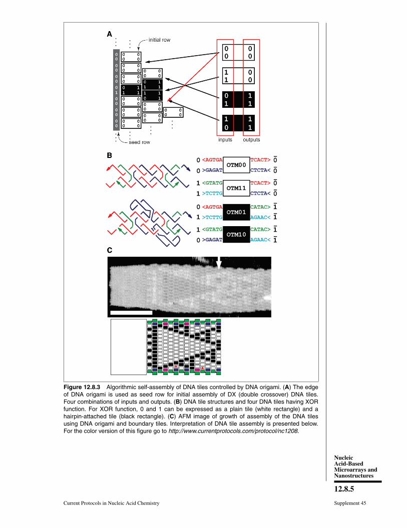
To control the crystal growth of a self-assembled pattern from DNA tiles, DNAorigami was used as a seed of the firstrow of input information, and then the log-ical operation exclusive disjunction (XOR)was performed with algorithmic self-assembly(Fig. 12.8.3; Fujibayashi et al., 2008). DNAsequence information representing 0 or 1 wasintroduced onto the four ends of the double-crossover (DX) tiles, and information repre-senting 0 or 1 was also displayed on theDX tiles using DNA hairpins for direct vi-sualization of the 0/1 patterns. When self-assembly of tiles occurs correctly, the pat-tern of the assembled DX tiles (Sierpinskitriangle) (Rothemund et al., 2004) is formedstarting from the first row of the template DNAorigami. Using border tiles to control the shapeof the self-assembly, about 300 DX tiles as-sembled to form a pattern, and the error rateper tile was 1.4%. In addition, using a similarmethod, DNA origami was used as a seed ofself-assembly of DX tiles, and the first row wasused for input information. The accuracy ofinformation transmission obtained by control-ling the width of the self-assembly was quitehigh (error rate 0.2%), and binary countingwas performed (Barish et al., 2009). Usingthe DNA origami system, accurate algorith-mic self-assembly and growth of assembliesof tiles can be performed with a low error rateduring self-assembly.
Three-Dimensional DNA OrigamiStructures
Considering the geometry of the periodicdouble-helical DNA structure, 3D structuresalso can be designed by the extension ofthe 2D DNA origami system. Two strate-gies to prepare the 3D DNA origami struc-tures have been developed; one is the bundlingof dsDNAs where the relative positioningbetween adjacent dsDNAs is controlled by
NucleicAcid-BasedMicroarrays andNanostructures
12.8.5
Current Protocols in Nucleic Acid Chemistry Supplement 45
Figure 12.8.3 Algorithmic self-assembly of DNA tiles controlled by DNA origami. (A) The edgeof DNA origami is used as seed row for initial assembly of DX (double crossover) DNA tiles.Four combinations of inputs and outputs. (B) DNA tile structures and four DNA tiles having XORfunction. For XOR function, 0 and 1 can be expressed as a plain tile (white rectangle) and ahairpin-attached tile (black rectangle). (C) AFM image of growth of assembly of the DNA tilesusing DNA origami and boundary tiles. Interpretation of DNA tile assembly is presented below.For the color version of this figure go to http://www.currentprotocols.com/protocol/nc1208.

DNA OrigamiTechnology
12.8.6
Supplement 45 Current Protocols in Nucleic Acid Chemistry
B
C
A
A B C
Figure 12.8.4 Design and construction of three-dimensional DNA origami structures.(A) Scheme for folding of the 2D pleated structure into the 3D multi-layered structure usingstaple strands connecting adjacent layers. Sectional views of the positions of the crossovers in themulti-layered structure sliced at 7 base-pair intervals. (B) Global twisted structures of 6-helix DNAbundles by selective deletion or insertion of nucleotides for changing the helical turns from normal10.5 base pairs to 10 or 11 base pairs. TEM images of the polymerized ribbons containing 10.5 bp,10 bp, and 11 bp helical pitches. (C) Global bending of 6-helix DNA bundles by deletion and inser-tion of nucleotides in the adjacent duplexes. Assembly of four components of quarter circle withthree-tooth (50-nm radius) and the TEM images of twelve-tooth gear. For the color version of thisfigure go to http://www.currentprotocols.com/protocol/nc1208.
crossovers; the other is the folding of 2Dorigami domains into 3D structures using in-terconnection strands. In the former method,developed by Shih and colleagues, relative po-sitioning of adjacent dsDNAs is geometricallycontrolled by the crossovers, and by arrang-ing the positions of the crossovers, tubularand multilayered structures were constructed(Fig. 12.8.4A) (Douglas et al., 2009a). Byincreasing or decreasing the number of basepairs between crossovers (in this case, two he-lical rotations in 21 base pairs), the relativepositional relationship between adjacent dsD-NAs is controlled. Using the rotational angle
of 240◦ for seven base pairs, three adjacentdsDNAs can be placed at a relative angle of±120◦ with crossovers separated every 7 or14 base pairs. By alternating this relative po-sitioning between adjacent dsDNAs, the du-plexes form a pleated surface. When adja-cent dsDNAs are placed to rotate in one di-rection, the contiguous duplexes finally forma six-helix bundled tubular structure. There-fore, when some parts of the pleated struc-tures are turned backward by introduction ofone-directional rotation of adjacent dsDNAs,the structures are folded to become a stackedlayer structure. In this case, to stabilize the 3D

NucleicAcid-BasedMicroarrays andNanostructures
12.8.7
Current Protocols in Nucleic Acid Chemistry Supplement 45
A
B
36 nm
keys
36 nm
42 nm
34 nm
48 nm
33 nm
Figure 12.8.5 Design and construction of three-dimensional structures from sequentially connected multiplerectangular plates. (A) DNA box structure made by folding of six DNA origami rectangles using interconnectionstrands introduced at the edges of the rectangles. The DNA box model reconstructed from cryo-EM images.(B) Controlled opening of the box lid using selective DNA strands (key). The lid opening event was monitored byFRET. For the color version of this figure go to http://www.currentprotocols.com/protocol/nc1208.
structures, adjacent layers of dsDNAs shouldbe further connected by crossovers. Becauseof the complexity and high density of the in-troduced crossovers, accurate folding into thetarget 3D structure requires week-long foldingtime. When the pleated structures were inte-grated as multi-layered structures, the repeat-ing units of six-helix bundled tubular struc-tures formed a honeycomb lattice, which wereviewed from the axial direction of the dou-ble helices. It was also possible to create morecomplex structures by perpendicularly joiningthese 3D structures. In addition, the wire-frame icosahedron structure was also assem-bled from the three double-triangle monomersmade of six helix-helix bundled tubes withconnections. The caDNAno software, which ispublicly available, has been developed to sup-port the design of these 3D structures (Douglaset al., 2009b).
Furthermore, using these layered struc-tures, new 3D structures were built by chang-ing the helical pitch of 11 or 10 base pairsfrom the perfect helical pitch of 10.5 basepairs (Dietz et al., 2009). When dsDNAshaving different helical pitches were bun-dled together, torque and repulsion betweenbase pairs caused overall structural changes
including twisting or 30◦ to 180◦ bending(Fig. 12.8.4B). Using these structures as build-ing blocks, left-handed or right-handed he-lical ribbon structures were prepared. In ad-dition, when angle-controlled duplex bundleswere connected to each other, a six-tooth gearand a spherical wireframe capsule were cre-ated (Fig. 12.8.4C).
Using a different strategy, a DNA boxstructure was created by folding multiple2D origami domains with interconnectingstrands (Andersen et al., 2009). Six inde-pendent rectangles were sequentially linked,and are designed to be folded using inter-connection strands in a programmed fashion(Fig. 12.8.5A). Analyses of the assembledstructure by AFM, cryo-electron microscopy,dynamic light scattering, and small-angle X-ray scattering indicated that the size was closeto the original design. The lid of the box couldbe opened using a specific DNA strand torelease the closing duplex, and the openingevent was monitored by FRET (Fig. 12.8.5B).Other types of DNA boxes have also beencreated using a similar method, which cancontrol inside and outside by adjusting thedirections of the crossovers at the connec-tion edges (Kuzuya and Komiyama, 2009).

DNA OrigamiTechnology
12.8.8
Supplement 45 Current Protocols in Nucleic Acid Chemistry
A tetrahedral structure was designed andconstructed from four preconnected alignedorigami triangles with an M13 scaffold strandand staples without folding independent 2Dplates (Ke et al., 2009).
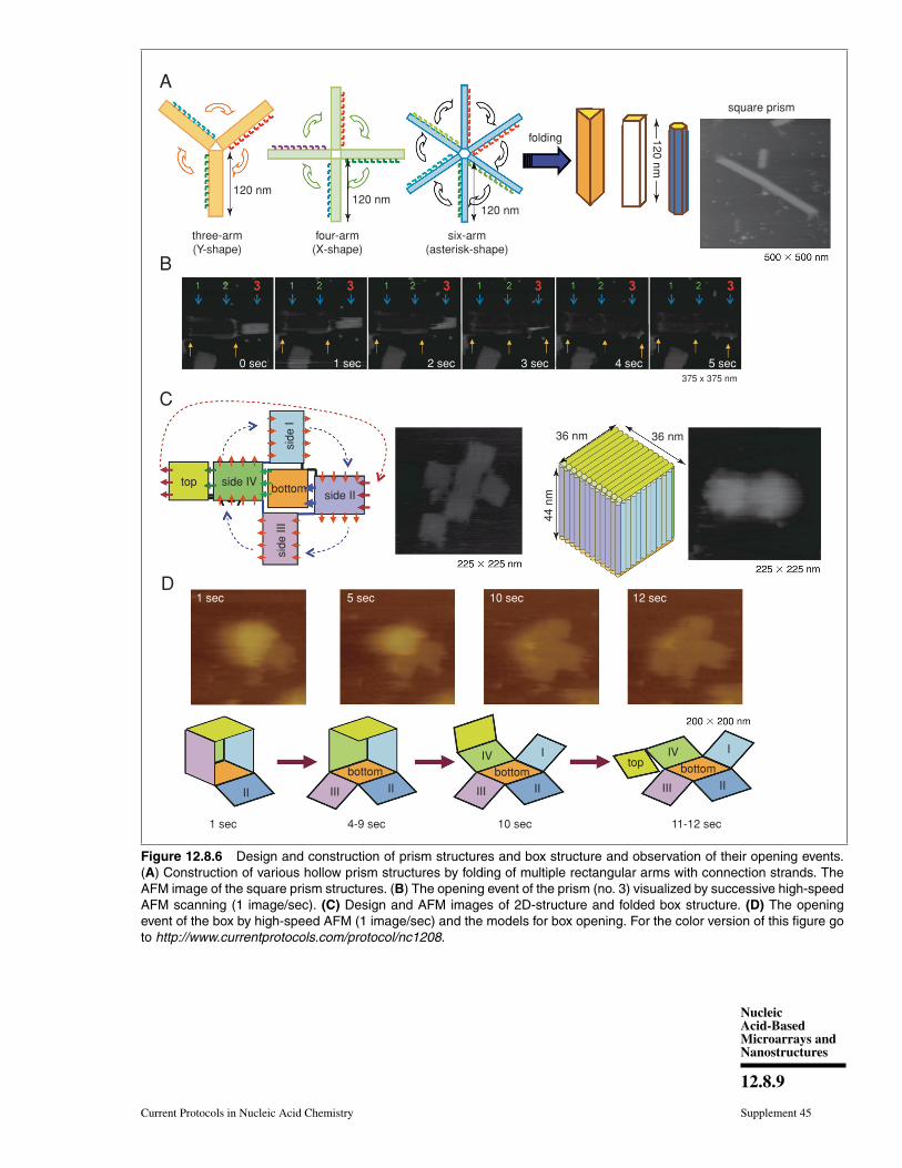
Using the strategy of folding the 2D origamistructures, we designed and prepared new hol-low prism structures (Fig. 12.8.6A) (Endoet al., 2009). To do this, we first preparednew DNA origami structures having three,four, or six arms, and then introduced connec-tion strands to these multi-arm DNA origamistructures to be folded into 3D structures. Af-ter introducing the interconnection strands onthe side edges of the arms and annealing,no original 2D structures were observed, andlinear fiber-like structures appeared. The 3Dstructures constructed by this method wereclosed tubular, and were characterized byAFM. Cryo-electron microscope images re-vealed that the 3D structures were hollowprisms. Successive AFM scanning of the sam-ple forced the closed structures to open into 2Dstructures (Fig. 12.8.6B). The tube-openingprocess was observed by high-speed AFMimaging, which can successively obtain oneAFM image per second. The prism struc-tures completely opened with different scan-ning numbers from once to 30 times, de-pending on the individual prisms. The openedprisms never reverted to their original multi-arm structures. After opening, the 2D structureformed a single rectangle of ∼130 × 90 nm,and the scaffold strand could be observed onthe opened 2D structure.
We further designed and constructed acuboid structure using the design of the squareprism structure (Endo et al., 2011a). We usedthe DNA origami method to prepare six rect-angular DNA origami plates that were foldedinto 3D box structures using interconnectionstrands (Fig. 12.8.6C). Six rectangular plateswere designed, and the connection strandswere introduced at the sides of the top andbottom plates to enable the prism structure tobe closed as a box structure of 36 × 36 × 44–nm in size. The six rectangles were formedafter annealing without connection strands.After annealing the staple strands with con-nection strands, the closed structures wereobserved by AFM. Dynamic light-scatteringanalysis showed the structure to be monodis-perse (89%) and about 68 nm in diameter,which was similar to the designed size (67 nm).The box-opening event was observed usinghigh-speed AFM. Successive scanning of the
sample converted the closed 3D structure into2D structures (Fig. 12.8.6D). The morphologi-cal changes occurred over 10 sec, which was adetectable time scale for our AFM instrument.AFM also enabled us to identify the individualplates involved in the opening process.
The time scale for morphological changesof the 3D structures was slow enough tobe observed and characterized by high-speedAFM imaging. Dimensional conversion of 2Dinto 3D could become a foundation tech-nology for the manipulation of nanostruc-tures; it is expected to cage and releasemolecules in the designed nanospace, and toenable chemical or enzymatic reactions to beperformed.
Modification and Functionalization ofTwo-Dimensional DNA OrigamiStructures
One of the most important features of DNAorigami is that each individual position onthe 2D structure contains different sequenceinformation. This means that the functionalmolecules and particles that are attached tothe staple strands can be positioned at desiredsites on the 2D structure.
To date, by directly coupling gold particleswith the staple DNA, gold nanoparticles havebeen selectively placed on a DNA origami(Sharma et al., 2008; Ding et al., 2010). Byconjugating ligands or aptamers with staplestrands, selective protein modification wasperformed on the 2D structures (Chhabraet al., 2007; Rinker et al., 2008; Kuzuya et al.,2009; Shen et al., 2009). Yan and colleaguesintroduced single-stranded DNAs comple-mentary to target RNAs to detect them on theDNA origami surface at the single molecularlevel by AFM (Fig. 12.8.7; Ke et al., 2008).Even though samples containing target RNAwith large amounts of cell-derived RNAswere used, the binding of target RNA couldonly be visualized, and nonspecific bindingwas not observed. Once DNA origami tilescarrying different types of complementaryDNAs were labeled with specific hairpinDNA markers, binding of RNA targets couldbe identified from the specific hairpin markerson the DNA origami even though the differentorigami tiles were mixed. In this study, thedetection limit of RNA molecules was about1000 molecules, meaning that the target RNAcould be directly detected from a single cellwithout PCR amplification.
NucleicAcid-BasedMicroarrays andNanostructures
12.8.9
Current Protocols in Nucleic Acid Chemistry Supplement 45
A
B
C
D
square prism
folding
120 nm120 nm
120 nm
six-arm(asterisk-shape)
four-arm(X-shape)
three-arm(Y-shape)
1 sec 5 sec
side IIbottom
4-9 sec 10 sec 11-12 sec1 sec
II II II IIIIIIIIIII
I IIVIVbottom bottom bottom
side IV
side
Isi
de II
I
top
top
10 sec 12 sec
36 nm 36 nm
44 n
m
120 nm
375 x 375 nm
0 sec 1 sec 2 sec 3 sec 4 sec 5 sec
Figure 12.8.6 Design and construction of prism structures and box structure and observation of their opening events.(A) Construction of various hollow prism structures by folding of multiple rectangular arms with connection strands. TheAFM image of the square prism structures. (B) The opening event of the prism (no. 3) visualized by successive high-speedAFM scanning (1 image/sec). (C) Design and AFM images of 2D-structure and folded box structure. (D) The openingevent of the box by high-speed AFM (1 image/sec) and the models for box opening. For the color version of this figure goto http://www.currentprotocols.com/protocol/nc1208.

DNA OrigamiTechnology
12.8.10
Supplement 45 Current Protocols in Nucleic Acid Chemistry
C
A B
60 nm
C-mycrag-1
C-mycrag-1
control
Withouttargets
Withtargets
controlstiffened probe with target
target
probe
index
AFM cantilever
90 nm
Figure 12.8.7 Detection of target RNA by hybridization with probe DNA strands introduced on the DNAorigami. (A) The method used for imaging the hybridization of target RNA to a probe DNA on the DNA origami.(B) Multiple DNA probes complementary to the target RNAs were introduced onto the DNA origami, andhairpin DNAs were also introduced as an index for identifying the probe strand. (C) AFM images of binding oftarget RNA to the probe strands. Specific DNA probes can be identified by the corresponding index. For thecolor version of this figure go to http://www.currentprotocols.com/protocol/nc1208.
Selective bond cleavage and bond forma-tion reactions were performed on the DNAorigami surface. Target organic molecules hav-ing specific reactivity were introduced intospecific positions on the DNA origami. Re-ductive cleavage of disulfide bonds and oxida-tive cleavage of olefin by singlet oxygen werecarried out on the DNA origami surface, andthe reactions quantitatively proceeded at thesingle molecular level (Voigt et al., 2010). Inaddition, the amide bond formation and clickreactions were performed with 80% to 90%yield, and three successive reactions were alsoperformed (Fig. 12.8.8; Voigt et al., 2010).The monitoring of these chemical reactionswas performed by cleavage of biotin-attachedchemical linkers and bond formation with
biotin-tethered functional groups, which canbe labeled with streptavidin for visualizationby AFM.
The selective placement of nanomaterialshas been carried out using the unique prop-erty of the DNA origami. Incorporated single-stranded DNAs on DNA origami controlledthe positioning of two DNA-modified carbonnanotubes into cross-junction on the both sidesof DNA origami (Maune et al., 2010). Theposition-controlled carbon nanotubes were ap-plied to create a single molecular device,which showed a field-effect transistor-like be-havior.
In another development, DNA origamitechnology met top-down nanotechnologyincluding semiconductor processing. Fine

NucleicAcid-BasedMicroarrays andNanostructures
12.8.11
Current Protocols in Nucleic Acid Chemistry Supplement 45
B
AAz
Es
Al
(AI)cu(I), THTA
(Az)cu(I), THTA
biotin biotin
HN
HN
NH
NH
NHHN
biotin
biotin
O
O
OO
O
O
OO
O
HN
HN
HN
O
O
S
S
S
OO
O
N NO
O
ON3
NH2N3
N3
(Es)
249 counted84% yield
300 nm 300 nm 300 nm 300 nm
197 counted90% yield
227 counted84% yield
180 counted69% yield
Figure 12.8.8 Single chemical reaction on the DNA origami. (A) Reactive groups (azido-, amino-, and alkyne) wereincorporated on the DNA origami by conjugation with staple DNA strands. Then, the coupling reactions were per-formed using the biotin-attached functional groups. The completion of the reactions was visualized by binding ofstreptavidin. (B) AFM images of the three individual reactions and three-successive reaction by treatment of threebiotin-attached functional groups. Yields are presented below the images. For the color version of this figure go tohttp://www.currentprotocols.com/protocol/nc1208.
triangular origami-binding sites on the surfacewere fabricated by electron-beam lithographyand dry etching. Origami-binding sites on theSiO2 surface passivated with TMS (trimethyl-silane) and single-layer or origami-bindingsites on the DLC (diamond-like carbon) wereused for the alignment of the triangularorigami tiles. By the addition of triangularorigami, origami tiles were selectively alignedto the binding sites depending on the size of thesites (Fig. 12.8.9) (Kershner et al., 2009). Thehydrophilic surface of the binding sites passi-vated with TMS is considered to be a drivingforce for binding the DNA origami, whereasthe interactions with binding sites on the DLCremained unclear. Using the various shapes of
binding sites on the surface, multiple origamitriangles were attached selectively dependingon the shape of the binding sites. Using a sim-ilar method, gold particles bound to the threevertices of a DNA triangle have been suc-cessfully aligned to the origami-binding siteswith controlled orientation and arrangements(Hung et al., 2010).
From these studies, functional moleculesand nanoparticles can be selectively placedonto specific positions on the DNA origamiin a programmed fashion. The DNA origamisystem can be integrated in combination withthe top-down nanotechnology. These methodscan be applied to create nanoscale deviceswith novel functionality when the functional

DNA OrigamiTechnology
12.8.12
Supplement 45 Current Protocols in Nucleic Acid Chemistry
A
B
~100 mMMgCl2
binding sites forDNA origami
Figure 12.8.9 Alignment of DNA triangles onto the fabricated surfaces. (A) Fabricated triangularorigami-binding sites were used for the alignment of DNA triangles. (B) Binding of DNA trianglesonto the binding sites of TMS-layered SiO2 surface (left) and DLC surface (right). Scale bar:500 nm. For the color version of this figure go to http://www.currentprotocols.com/protocol/nc1208.
origami is precisely integrated on the fabri-cated surface.
Application to Single BiomolecularImaging
Control of DNA methylation and DNArepair in the DNA nanospace
Direct observation of the enzymes inter-acting with DNA is expected to be one ofthe ultimate technologies for investigating themechanical behavior of enzymes. We createdan AFM-based observation system for singlemolecular observations of various enzymesusing a designed DNA origami scaffold. DNAmodification using enzymes often requiresbending specific DNA strands to facilitatethe reaction. The DNA methylation enzymeEcoRI methyltransferase (M.EcoRI) bendsdsDNA by 55◦ to 59◦ during the reaction, asthe methyl transfer reaction proceeds (Young-blood and Reich, 2006). To control the methyltransfer reaction of M.EcoRI and examine thestructural effect on methylation, we designedand prepared a 2D DNA scaffold nameda “DNA frame” that accommodates twodifferent lengths of dsDNA fragments, a tense64mer dsDNA and a relaxed 74mer dsDNA
(Fig. 12.8.10; Endo et al., 2010a). High-speed AFM revealed the different dynamicmovements of the dsDNAs and complexes ofM.EcoRI with 64mer and 74mer dsDNAs. Af-ter treatment of the dsDNA in the DNA framewith M.EcoRI and the subsequent digestionwith restriction enzyme EcoRI, AFM analysisrevealed that, compared with the 64merdsDNA, the 74mer dsDNA was less effec-tively cleaved, indicating that the methylationpreferentially occurred in the relaxed 74merdsDNA rather than in the tense 64mer dsDNA.Biochemical analysis of the products aftermethylation and specific digestion using real-time PCR supported the above results. Theseresults indicate the importance of structuralflexibility for the bending of dsDNA duringthe methyl transfer reaction with M.EcoRI.Therefore, the DNA methylation can be regu-lated using the structurally controlled dsDNAsconstructed in the DNA frame nanostructure.
We next developed a novel method forthe analysis of DNA repair by employ-ing a nanoscale DNA chip containing var-ious dsDNAs and using high-speed AFM(Endo et al., 2010b). We employed DNAbase-excision repair enzymes, 8-oxoguanineglycosylase, and T4 pyrimidine dimer

NucleicAcid-BasedMicroarrays andNanostructures
12.8.13
Current Protocols in Nucleic Acid Chemistry Supplement 45
A C D
E F
B
74mer duplex
64mer duplex100 nm
A
A
B
B
C
C
D
D
20 nm80
nm
40 nm
40 n
mFigure 12.8.10 Control of the enzyme reactions in the DNA origami scaffold. (A, B) DNA frame structure de-signed for incorporation of two different dsDNAs; tense 64mer dsDNA and relaxed 74mer dsDNA having thespecific sequence for M.EcoRI at the center. AFM images of the DNA frame (C), two-dsDNA attached DNA frame(D), and M.EcoRI bound to the 64mer dsDNA (E) and the 74mer (F) dsDNA. For the color version of this figure goto http://www.currentprotocols.com/protocol/nc1208.
glycosylase, for the analysis of the reactionon the defined DNA nanostructure. These en-zymes have glycosylase/AP–lyase activity forremoving the damaged nucleobases and cleav-ing the DNA strand. We placed various ds-DNAs with a damaged base onto a DNAnanochip as a dsDNA cassette and analyzedthe repair reaction at a single molecular level.We placed two different lengths of substratedsDNAs, tensed 64mer, and relaxed 74mer ds-DNAs, on a DNA nanochip to examine thestructural effect on the glycosylase/AP−lyaseactivity, including cleavage of the DNA strandand trapping of reaction intermediates. The re-laxed 74mer dsDNA was effectively trappedwith NaBH4 reduction and cleaved comparedwith the 64mer dsDNA. In addition, dynamicmovement of the enzymes and the single DNArepair reaction were directly observed on theDNA nanochip using a high-speed AFM imag-ing system. The DNA nanochip system servesto elucidate the detailed properties of the repairenzymes by direct observation of the events in-volved in DNA repair.
This method can be used for other DNA-modifying and repair enzymes that bend thedouble helix during the enzymatic reaction.The method can be extended to the direct ob-
servation of various enzymatic phenomena inthe designed nanoscale space.
Visualization of DNA structural changeThe formation and disruption of the sin-
gle G-quadruplex structure were observed inthe nanospace (Sannohe et al., 2010). For thispurpose, we employed a DNA frame scaffold.To place the G-rich sequences, we preparedtwo unique DNA strands (G-strands) that con-tained single-stranded G-rich overhangs at themiddle for the formation of the interstrandG-quadruplex (Fig. 12.8.11). Three G-tractswere placed in the upper G-strand, whereasthe lower strand had a single G-tract. The in-troduced strands were parallel to each other. Inthe presence of K+, the G-strands in the DNAframe clearly showed an X-shaped structure,which indicated the formation of an interstrandG-quadruplex (Fig. 12.8.11, right panel). Theefficiency of the X-shaped formation was 44%using relaxed dsDNA. We further tried to di-rectly observe the dynamic formation of the G-quadruplex in real time by high-speed AFM.During scanning of the sample in the pres-ence of K+, the two G-strands maintained aparallel state for a given period, and then they

DNA OrigamiTechnology
12.8.14
Supplement 45 Current Protocols in Nucleic Acid Chemistry
Figure 12.8.11 Visualization of G-quadruplex formation using the structural change of twodsDNAs placed in the DNA frame. In the presence of KCl, the parallel-shape changes to theX-shape by connection at the center of two dsDNAs via G-quadruplex formation. For the colorversion of this figure go to http://www.currentprotocols.com/protocol/nc1208.
suddenly formed an X shape. In a similar fash-ion, we tried to follow the disruption of theG-quadruplex in the absence of K+. The Xshape remained unchanged for a while, andthen it reverted to the parallel state under AFMscanning.
We thus successfully achieved the dynamicformation and disruption of G-quadruplexesby monitoring the changes in the DNA nanos-tructure by high-speed AFM imaging. This isthe first report of the real-time observation ofa reversible conformational change of a DNAstructure. The method is applicable for directobservation of various known conformationalchanges in nucleic acids.
Application to DNA molecular machinesOne of the goals of the artificial molec-
ular system is achieving fully controllablemovement of the molecular machine. DNAmolecular machines are operated by addingand removing specific DNA strands for com-plex movements. For this purpose, an ex-tra sequence called a “toehold” is attachedto the end of the DNA strand. If a DNAstrand complementary to a toehold-containingstrand is added, the toehold-containing onecan be selectively removed by DNA strand ex-change. The thermodynamic stabilization en-ergy works as “fuel” during hybridization to
provide the mechanical motion of DNA ma-chines. Using this strategy, DNA tweezers thatperform close-open motions were constructed(Yurke et al., 2000). Also created were twoexamples of a DNA walking device: a DNAwalker with two legs that can control the direc-tion of motion and a DNA motor that can moveforward autonomously by the cleavage of theDNA restriction enzyme (Bath and Turber-field, 2007).
Seeman and colleagues have developed acontrollable mechanical rotation device calleda “PX-JX2 device,” which can rotate two adja-cent ends of the dsDNAs by 180◦ in either thePX (paranemic crossover) or JX2 (its topoiso-mer) state (Yan et al., 2002; Liao and Seeman,2004; Ding and Seeman, 2006). Two PX-JX2 devices were introduced onto the origamiscaffold at two specific sites to capture DNAnanostructures with four sticky ends throughthe two sets of two complementary strandson the PX-JX2 devices (Gu et al., 2009). ThePX and JX2 states of the two devices allowedthe binding of four different capture moleculeswith four different patterns of sticky ends cor-responding to each rotational operation. LargeDNA triangles were introduced onto the cap-ture molecules as AFM markers for identifica-tion. Through the use of the four combinationsof the PX and the JX2 state, the specific capture

NucleicAcid-BasedMicroarrays andNanostructures
12.8.15
Current Protocols in Nucleic Acid Chemistry Supplement 45
molecules can be trapped between the devices.In addition, one target capture molecule out ofthe mixture of four different capture DNAs cancorrectly bind to the specific state of the deviceafter heating to dissociate nonspecific capturemolecules (error correction).
In addition, Seeman and colleagues ex-amined the movement of a two-legged DNAwalker along tracks constructed in DNAnanostructures (Omabegho et al., 2009),and created a new DNA walker to oper-ate the assembly line on the DNA origami(Fig. 12.8.12A; Gu et al., 2010). Three PX-JX2 devices were fixed onto the DNA origami,and the DNA walker moved along a path-way predetermined by the operation from out-side. The movements of all the devices andthe DNA walker were fully controlled by spe-cific DNA strands. PX-JX2 devices carryinggold particles (AuNPs) of various sizes andamounts can pass to the walker by rotationaloperation when the DNA walker is locatednearby. The DNA walker moved in one di-rection along the track. Three PX-JX2 devicesdelivered AuNPs to the walker by the opera-tion of the devices, and then the DNA walkerpicked up the AuNPs at the specific positions.The DNA walker, which eventually picked upthree AuNP-bound DNAs, had a 43% yield.Because the on-off operation of the PX-JX2
device delivering AuNPs was fully controlledby the specific DNA strand, the final targetproduct was obtained in high yield (90%) witha very low error rate (1%). Moreover, usingthe on-off operation of three PX-JX2 devices,eight patterns of AuNPs bound to the DNAwalker were obtained.
Stojanovic, Yan, and colleagues created aDNA nanomachine called a “DNA spider,”which has three legs and one capture strandand moves along various patterned tracks con-structed on the DNA origami (Fig. 12.8.12B;Lund et al., 2010). A DNAzyme that canhydrolyze RNA was incorporated in the threelegs of the DNA spider. Single-strandedDNA/RNA chimeras were incorporated intothe DNA origami as a track. A DNA spiderwas introduced and fixed at the startingposition in the DNA origami via a capturestrand, and was then released from the startpoint using a specific DNA strand. Thenthe DNA spider bound to the DNA/RNAchimeric strands in the track, and migratedalong the predetermined track with cleavingDNA/RNA chimeric strands by DNAzymesin the legs. Finally, the spider stopped at thespecific DNA strand, which did not containcleavable RNA. This study shows that start,
walk, and stop can be programmed intothe predesigned track and DNA spider. Themovements of the DNA spider were analyzedin real time by high-resolution total internalreflection microscopy, and the spiders werefound to have moved on the DNA origami at3 nm/min.
We have created a DNA nanomachine thatcan move along the designed track constructedin the DNA origami (Fig. 12.8.13); the track onthe DNA scaffold was constructed for obser-vation of the multistep movement of a specificDNA strand (Wickham et al., 2011). MultiplessDNAs (stators) were introduced as a track forhybridization of a complementary strand (mo-tor strand). When the motor strand hybridizesto the specific stator, subsequent cleavage ofthe stator/motor duplex by a restriction en-zyme, Nt.BbvCI, removes the short ssDNAof the stator; the motor strand binds to thenext stator by branch migration and then fi-nally steps forward. We expected the multistepmovement would be achieved by the turn-overof the enzymatic reactions. Seventeen statorswere introduced onto the DNA origami scaf-fold as a motor track to observe the move-ments of the motor strand. The stator/motorduplex was introduced into site 1 in the motortrack using a DNA scaffold lacking the sta-ple strand at site 1. After annealing, a singlespot was observed at site 1, and the incorpora-tion proceeded quantitatively. Then the DNAscaffold carrying the stator/motor at site 1 wasincubated for 0 to 3 hr with Nt.BbvCI to ex-amine migration of the motor strand along theDNA motor track. The motor strand was im-aged as a single spot of the duplex on the DNAorigami scaffold. We observed one-directionaland time-dependent movement of the motorstrand along the motor track. Furthermore, themovement of the motor strand along the mo-tor track was directly observed by high-speedAFM. The stator/motor duplex spot movedforward along the motor track with scanningevery 5 sec for each AFM image. From thekymograph analysis, the distance of the mo-tor strand movement corresponded to the dis-tance between the adjacent stators, indicatingthat the movement occurred stepwise on thetrack.
We thus designed and constructed a con-trolled DNA nanomachine system in whicha motor strand moves along the track in theDNA origami scaffold. We observed the au-tonomous movement of the motor strand byenzymatic cleavage. The stepwise movementof the motor strand was directly observed byhigh-speed AFM imaging. This method can

DNA OrigamiTechnology
12.8.16
Supplement 45 Current Protocols in Nucleic Acid Chemistry
A
B
PX PX
product
dA
rA
substrate
spider bodyspider body
8-17 DNA enzyme leg
8-17DNA
enzyme
origami origami
capture leg
25 nm
(vi)
(v)
(iv)
(iii)
(ii)
(i)
(vi)
(v)
(iv)
(iii)
(ii)
(i)
PX
C1 C1C1
H1H1H1
A-2 A-2 A-2A-4A-1
A-4A-1
A-4A-1
Figure 12.8.12 DNA nanomachines walking on the DNA origami. (A) Assembly line of gold nanoparticle (AuNP) usinga DNA walker. The DNA walker has four feet for walking on the selective position on the DNA origami and three handsto capture AuNP. AuNP is transferred to the DNA walker from the PX-JX2 device in the PX state by toehold-hybridization.The DNA walker stops at three specific places to capture AuNPs in PX state. Stepwise AFM images of AuNPs attachedon the DNA walker after the operations. (B) DNA spider has three legs consisting of a DNAzyme to cleave the RNA(rA)-containing DNA strand introduced on the DNA origami. The DNA spider starts by releasing from the starting point,which is placed with the capture leg, and then walking on the substrate track by cleaving the substrates. The walkerstops when it encounters the uncleavable substrate strands lacking RNA (dA). For the color version of this figure go tohttp://www.currentprotocols.com/protocol/nc1208.
be applied for the development of a nanoma-chine that can transport specific molecules andperform more complicated movements on ex-panded DNA nanostructures.
CONCLUSION AND PROSPECTSA wide variety of designs of 2D and 3D
structures around 100 nm in size has been ob-tained using DNA origami. Compared withthe use of small DNA assemblies, the DNAorigami method saves experimental labor and
eliminates uncertainties. In the relatively shorttime since the DNA origami method wasfirst reported in 2006 (Rothemund, 2006),the creation of multidimensional structures,functionalization, single molecular observa-tion, and the construction of molecular ma-chines have been achieved. Connection withtop-down nanotechnology, including semi-conductor processing techniques, has al-ready started using the functionalized DNAorigami.

NucleicAcid-BasedMicroarrays andNanostructures
12.8.17
Current Protocols in Nucleic Acid Chemistry Supplement 45
B
A Cmotor-strand
motor-track
site 1
site 1
site 17
site 17
3 hr2 hr1 hr0 hr site 1
site 10
site 13
site 17
~100 nm
Nt. BbvCl
Figure 12.8.13 DNA motor walking on the DNA origami. (A) Motor-track (green ssDNAs) was constructedon the DNA origami and the movement of the DNA motor (red ssDNA) was examined. (B) Time-dependentmovement of a DNA motor. (C) Stepwise movement of a DNA motor observed in real-time by high-speedAFM. For the color version of this figure go to http://www.currentprotocols.com/protocol/nc1208.
It would be possible to use a func-tional DNA origami as a module to expresshigher-level functionalities by assemblingthem in a programmed fashion. It is extremelydifficult to arrange small molecules to preparedesired structures; however, if preassembled100-nm-size structures can be organized andpurified to exclude the incomplete structures,the usefulness is greatly improved.
DNA origami allows precise placementand manipulation of functional molecules andbiomolecules and is also available for con-struction of a designed nanospace for chem-ical and biological reactions. Furthermore,since the observation of the movement ofbiomolecules in nanospace has become possi-ble, it is possible to create devices that visual-ize the reaction and behavior of biomoleculesin the designed nanospace. This technologyalso opens the way to express complex func-tionality caused by the programmed organiza-tion of many different modules seen in livingsystems.
LITERATURE CITEDAndersen, E.S., Dong, M., Nielsen, M.M., Jahn,
K., Subramani, R., Mamdouh, W., Golas,
M.M., Sander, B., Stark, H., Oliveira, C.L.,Pedersen, J.S., Birkedal, V., Besenbacher, F.,Gothelf, K.V., and Kjems, J. 2009. Self-assembly of a nanoscale DNA box with a con-trollable lid. Nature 459:73-76.
Barish, R.D., Schulman, R., Rothemund, P.W., andWinfree, E. 2009. An information-bearing seedfor nucleating algorithmic self-assembly. Proc.Natl. Acad. Sci. U.S.A. 106:6054-6059.
Bath, J. and Turberfield, A.J. 2007. DNA nanoma-chines. Nature Nanotechnol. 2:275-284.
Chhabra, R., Sharma, J., Ke, Y., Liu, Y., Rinker,S., Lindsay, S., and Yan, H. 2007. Spatially ad-dressable multiprotein nanoarrays templated byaptamer-tagged DNA nanoarchitectures. J. Am.Chem. Soc. 129:10304-10305.
Dietz, H., Douglas, S.M., and Shih, W.M. 2009.Folding DNA into twisted and curved nanoscaleshapes. Science 325:725-730.
Ding, B., Deng, Z., Yan, H., Cabrini, S.,Zuckermann, R.N., and Bokor, J. 2010. Goldnanoparticle self-similar chain structure orga-nized by DNA origami. J. Am. Chem. Soc.132:3248-3249.
Ding, B. and Seeman, N.C. 2006. Operation of aDNA robot arm inserted into a 2D DNA crys-talline substrate. Science 314:1583-1585.
Douglas, S.M., Dietz, H., Liedl, T., Hogberg, B.,Graf, F., and Shih, W.M. 2009a. Self-assembly

DNA OrigamiTechnology
12.8.18
Supplement 45 Current Protocols in Nucleic Acid Chemistry
of DNA into nanoscale three-dimensionalshapes. Nature 459:414-418.
Douglas, S.M., Marblestone, A.H., Teerapit-tayanon, S., Vazquez, A., Church, G.M.,and Shih, W.M. 2009b. Rapid prototyp-ing of 3D DNA-origami shapes withcaDNAno. Nucleic Acids Res. 37:5001-5006.
Endo, M. and Sugiyama, H. 2009. Chemicalapproaches to DNA nanotechnology. Chem-BioChem 10:2420-2443.
Endo, M. Hidaka, K. Kato, T., Namba, K., andSugiyama, H. 2009. DNA prism structures con-structed by folding of multiple rectangular arms.J. Am. Chem. Soc. 131:15570-15571.
Endo, M., Katsuda, Y., Hidaka, K., and Sugiyama,H. 2010a. Regulation of DNA methylation usingdifferent tensions of double strands constructedin a defined DNA nanostructure. J. Am. Chem.Soc. 132:1592-1597.
Endo, M., Katsuda, Y., Hidaka, K., and Sugiyama,H. 2010b. A versatile DNA nanochip for directanalysis of DNA base-excision repair. Angew.Chem. Int. Ed. 49:9412-9416.
Endo, M., Sugita, T., Katsuda, Y., Hidaka, K., andSugiyama, H. 2010c. Programmed-assemblysystem using DNA jigsaw pieces. Chem. Eur.J. 16:5362-5368.
Endo, M., Hidaka, K., and Sugiyama, H. 2011a.Direct AFM observation of an opening event ofa DNA cuboid constructed via a prism struc-ture.Org. Biomol. Chem. 9:2075-2077.
Endo, M., Sugita, T., Rajendran, A., Katsuda,Y., Emura, T., Hidaka, K., and Sugiyama, H.2011b. Two-dimensional DNA origami assem-blies using a four-way connector. Chem. Com-mun. 47:3213-3215.
Feldkamp, U. and Niemeyer, C.M. 2006. Ratio-nal design of DNA nanoarchitectures. Angew.Chem. Int. Ed. 45:1856-1876.
Fujibayashi, K., Hariadi, R., Park, S.H., Winfree, E.,and Murata, S. 2008. Toward reliable algorith-mic self-assembly of DNA tiles: A fixed-widthcellular automaton pattern. Nano Lett. 8:1791-1797.
Gu, H., Chao, J., Xiao, S., and Seeman, N.C. 2009.Dynamic patterning programmed by DNA tilescaptured on a DNA origami substrate. NatureNanotechnol. 4:245-248.
Gu, H., Chao, J., Xiao, S., and Seeman, N.C.2010. A proximity-based programmable DNAnanoscale assembly line. Nature 465:202-205.
Hogberg, B., Liedl, T., and Shih, W.M. 2009.Folding DNA origami from a double-strandedsource of scaffold. J. Am. Chem. Soc. 131:9154-9155.
Hung, A.M., Micheel, C.M., Bozano, L.D.,Osterbur, L.W., Wallraff, G.M., and Cha, J.N.2010. Large-area spatially ordered arrays of goldnanoparticles directed by lithographically con-fined DNA origami. Nature Nanotechnol. 5:121-126.
Ke, Y., Lindsay, S., Chang, Y., Liu, Y., and Yan,H. 2008. Self-assembled water-soluble nucleicacid probe tiles for label-free RNA hybridizationassays. Science 319:180-183.
Ke, Y., Sharma, J., Liu, M., Jahn, K., Liu, Y., andYan, H. 2009. Scaffolded DNA origami of aDNA tetrahedron molecular container. Nano.Lett. 9:2445-2447.
Kershner, R.J., Bozano1, L.D., Micheel, C.M.,Hung, A.M., Fornof, A.R., Cha, J.N.,Rettner, C.T., Bersani, M., Frommer, J.,Rothemund, P.W. and Wallraff, G.M. 2009.Placement and orientation of individual DNAshapes on lithographically patterned surfaces.Nature Nanotechnol. 4:557-561.
Kuzuya, A. and Komiyama, M. 2009. Design andconstruction of a box-shaped 3D-DNA origami.Chem. Commun. 28:4182-4184.
Kuzuya, A., Kimura, M., Numajiri, K., Koshi, N.,Ohnishi, T., Okada, F., and Komiyama, M. 2009.Precisely programmed and robust 2D strepta-vidin nanoarrays by using periodical nanometer-scale wells embedded in DNA origami assem-bly. ChemBioChem 10:1811-1815.
Liao, S. and Seeman, N.C. 2004. Translation ofDNA signals into polymer assembly instruc-tions. Science 306:2072-2074.
Lund, K., Manzo, A.J., Dabby, N., Michelotti, N.,Johnson-Buck, A., Nangreave, J., Taylor, S., Pei,R., Stojanovic, M.N., Walter, N.G., Winfree, E.,and Yan, H. 2010. Molecular robots guided byprescriptive landscapes. Nature 465:206-210.
Maune, H.T., Han, S.P., Barish, R.D., Bockrath,M., Iii, W.A., Rothemund, P.W., and Winfree,E. 2010. Self-assembly of carbon nanotubesinto two-dimensional geometries using DNAorigami templates. Nature Nanotechnol. 5:61-66.
Omabegho, T., Sha, R., and Seeman, N.C. 2009. Abipedal DNA Brownian motor with coordinatedlegs. Science 324:67-71.
Pound, E., Ashton, J.R., Becerril, H.A., andWoolley, A.T. 2009. Polymerase chain reactionbased scaffold preparation for the production ofthin, branched DNA origami nanostructures ofarbitrary sizes. Nano Lett. 9:4302-4305.
Rajendran, A., Endo, M., Katsuda, Y., Hidaka,K., and Sugiyama, H. 2011. Programmed two-dimensional self-assembly of multiple DNAorigami jigsaw pieces. ACS Nano 5:665-671.
Rinker, S., Ke, Y., Liu, Y., Chhabra, R., and Yan, H.2008. Self-assembled DNA nanostructures fordistance-dependent multivalent ligand-proteinbinding. Nature. Nanotechnol. 3:418-422.
Rothemund, P.W. 2006. Folding DNA to createnanoscale shapes and patterns. Nature 440:297-302.
Rothemund, P.W., Papadakis, N., and Winfree, E.2004. Algorithmic self-assembly of DNA Sier-pinski triangles. PLoS Biol. 2:e424.
Sannohe, Y., Endo, M., Katsuda, Y., Hidaka, K., andSugiyama, H. 2010. Visualization of dynamic

NucleicAcid-BasedMicroarrays andNanostructures
12.8.19
Current Protocols in Nucleic Acid Chemistry Supplement 45
conformational switching of the G-quadruplexin a DNA nanostructure. J. Am. Chem. Soc.132:16311-16313.
Seeman, N.C. 2003. DNA in a material world. Na-ture 421:427-431.
Sharma, J., Chhabra, R., Andersen, C.S., Gothelf,K.V., Yan, H., and Liu, Y. 2008. Toward re-liable gold nanoparticle patterning on self-assembled DNA nanoscaffold. J. Am. Chem.Soc. 130:7820-7821.
Shen, W., Zhong, H., Neff, D., and Norton, M.L.2009. NTA directed protein nanopatterning onDNA Origami nanoconstructs. J. Am. Chem.Soc. 131:6660-6661.
Voigt, N.V., Torring, T., Rotaru, A., Jacobsen, M.F.,Ravnsbak, J.B., Subramani, R., Mamdouh, W.,Kjems, J., Mokhir, A., Besenbacher, F., andGothelf, K.V. 2010. Single-molecule chemicalreactions on DNA origami. Nature Nanotech-nol. 5:200-203.
Wickham, S., Endo, M., Katsuda, Y., Hidaka, K.,Bath, J., Sugiyama, H., and Turberfield, A.J.2011. Direct observation of stepwise move-ment of a synthetic molecular transporter. Na-ture Nanotechnol. 6:166-169.
Yan, H., Zhang, X., Shen, Z., and Seeman,N.C. 2002. A robust DNA mechanical devicecontrolled by hybridization topology. Nature415:62-65.
Youngblood, B. and Reich, N.O. 2006, Conforma-tional transitions as determinants of specificityfor the DNA methyltransferase EcoRI. J. Biol.Chem. 281:26821-26831.
Yurke, B., Turberfield, A.J., Mills, A.P. Jr., Simmel,F.C., and Neumann, J.L. 2000. A DNA-fuelledmolecular machine made of DNA. Nature406:605-608.
Zhao, Z., Yan, H., and Liu, Y. 2010. A route to scaleup DNA origami using DNA tiles as foldingstaples. Angew. Chem. Int. Ed. 49:1414-1417.