rbca cover page
TRANSCRIPT
SUPPORTING INFORMATION FOR THE IMPLEMENTATION OF THE RISK BASED CORRECTIVE ACTION PROVISIONS FOR
MIAMI-DADE COUNTY
Department of Environmental Resources Management Pollution Remediation Section
Miami-Dade County
March 12, 2003

TABLE OF CONTENTS
Introduction Flow Charts Guidance Documents
SUPPORTING INFORMATION FOR THE IMPLEMENTATION OF THE CHAPTER 24 RISK BASED CORRECTIVE ACTION PROVISIONS
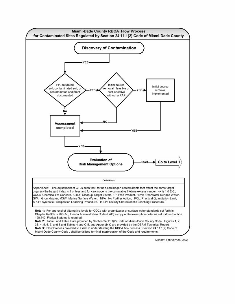
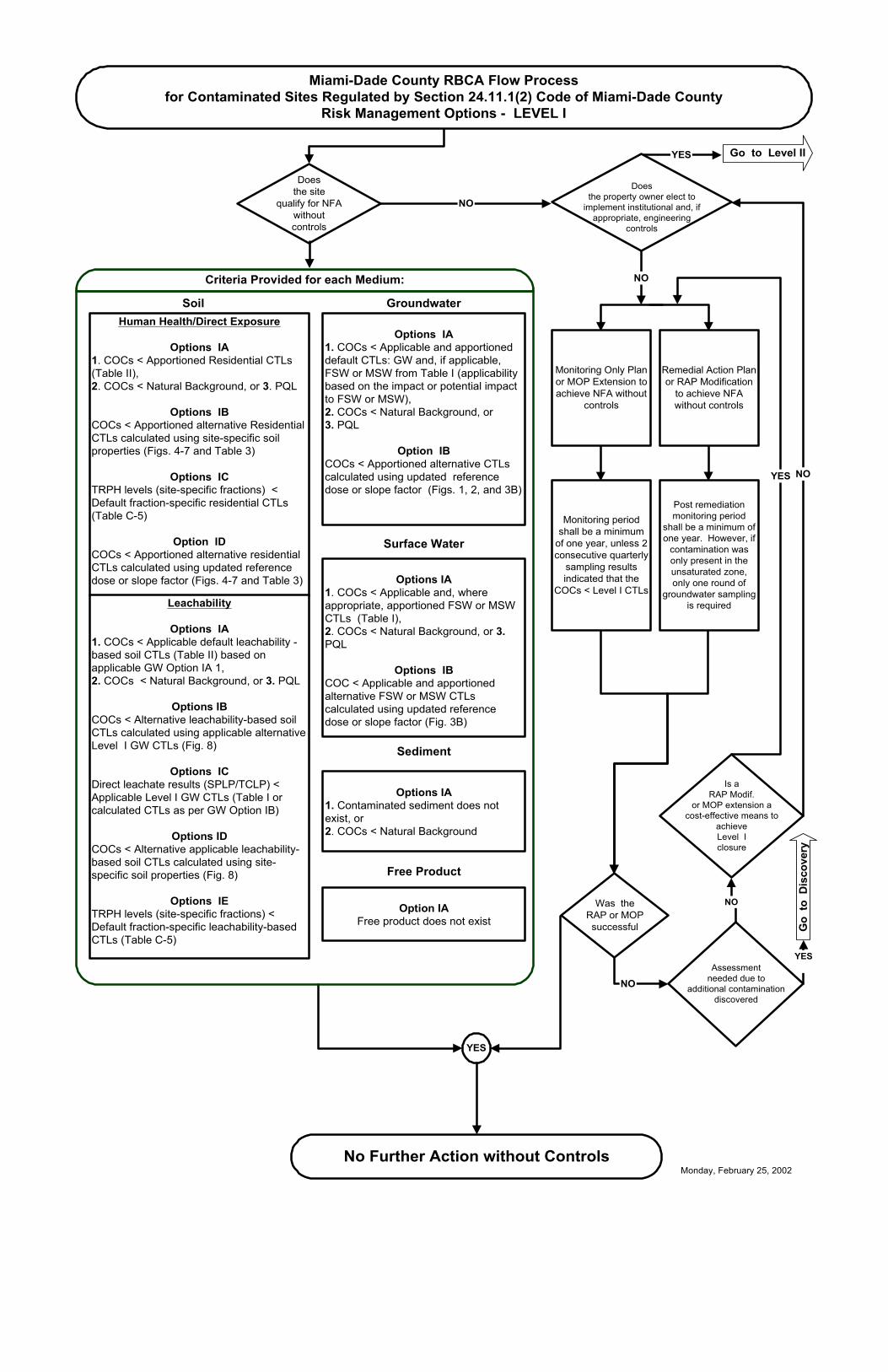
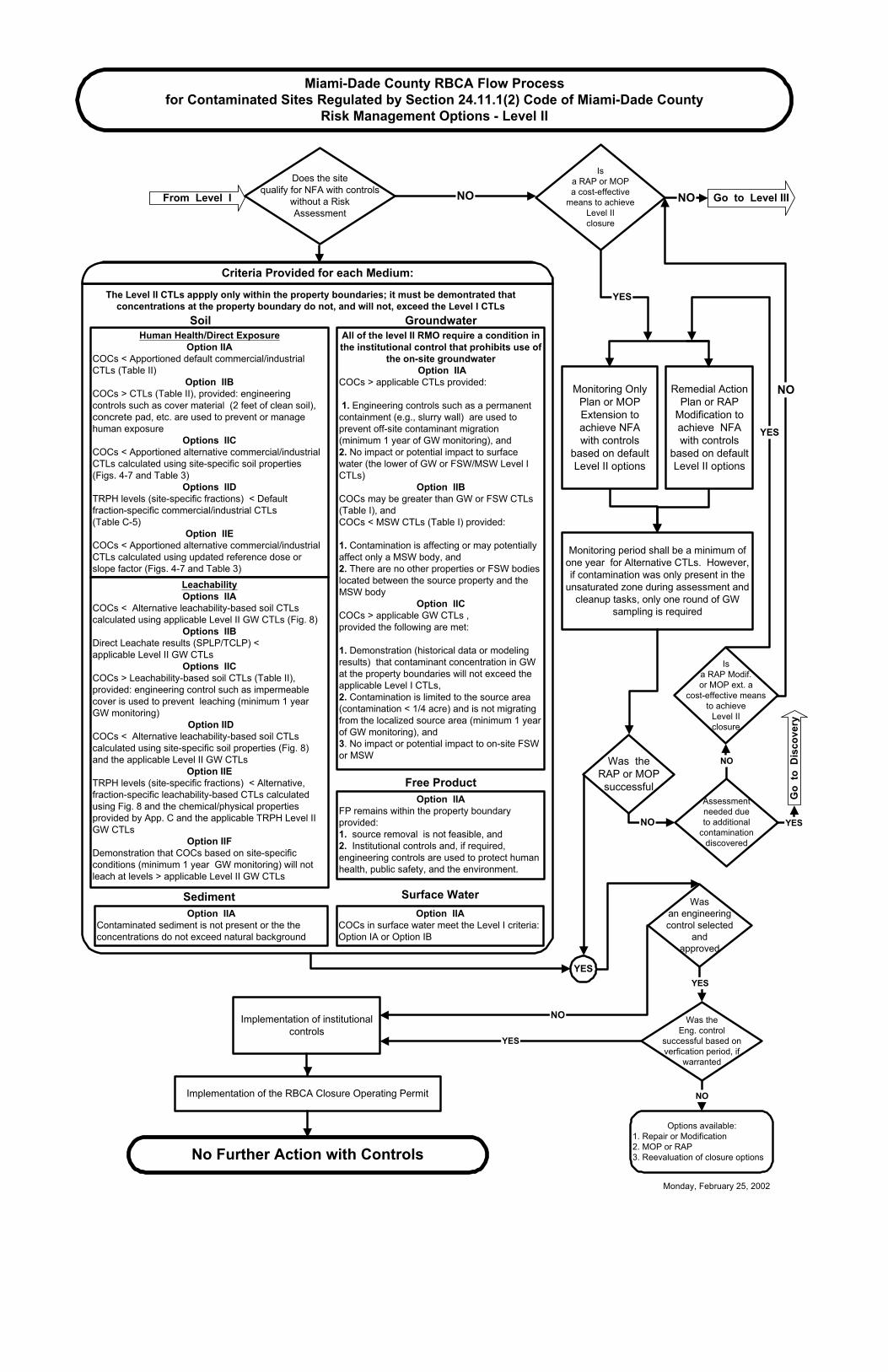
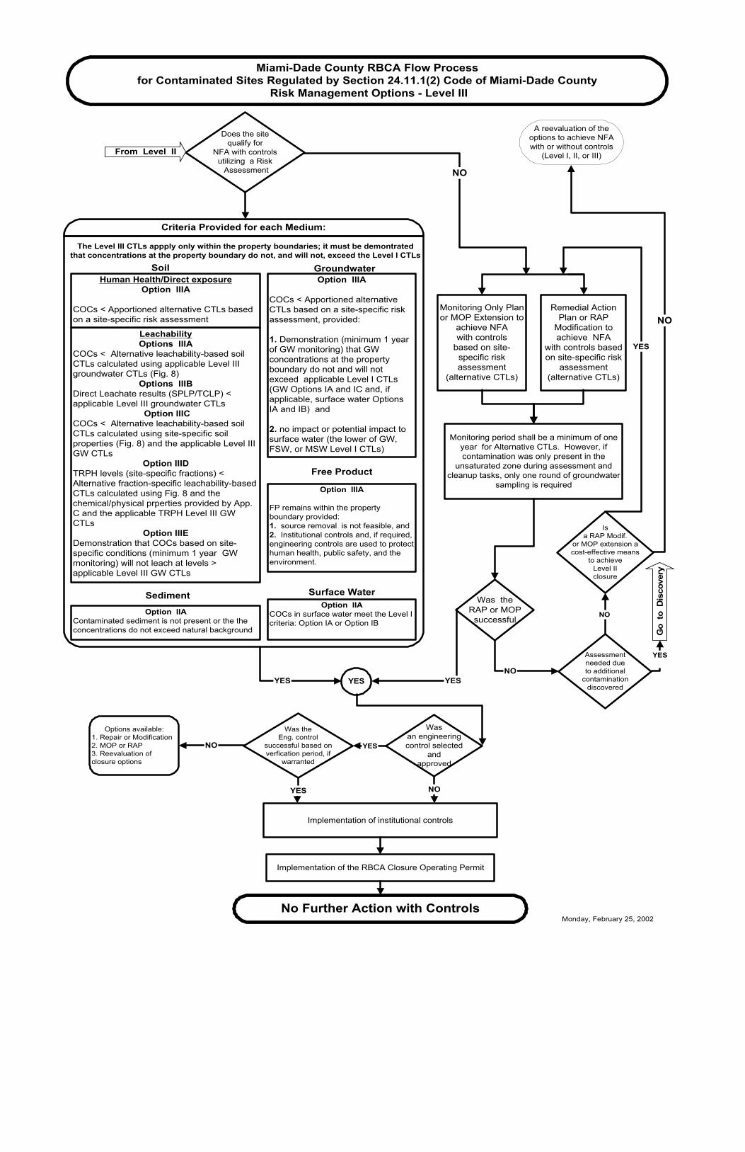
The flowcharts (Attachment A) and guidance documents (Attachment B) have been developed by DERM to facilitate the understanding and implementation of the risk based corrective action (RBCA) provisions, adopted by the Board of County Commissioners (BCC) on March 8, 2001 (Attachment C). These provisions, set forth in Section 24-11.1(2), Code of Miami-Dade County, Florida (“the Code”), provide numerical clean-up target levels (CTLs) for approximately four hundred contaminants and provide procedures for implementing and completing site rehabilitation activities (e.g., site assessment and remediation) to achieve a no further action status. The Chapter 24 RBCA provisions and the attached guidance documents apply to the cleanup of non-program sites; that is, sites that are not regulated by the State of Florida Petroleum, Brownfields or Drycleaning rules (Chapters 62-770, 785, and 782, F.A.C., respectively). Background In general, RBCA is a phased approach to site rehabilitation that integrates risk assessment principles and site-specific conditions with traditional assessment and remediation tasks to provide cost-effective options for site closure (i.e., no further action, NFA, or NFA with conditions) that are protective of human health and the environment. To enhance the clarity of the Chapter 24 RBCA process, the flowcharts depict the process in three distinct site rehabilitation levels, each of which offer a variety of risk management options (RMOs) for achieving site closure. Each level achieves the acceptable level of protection as set forth in Section 24-11.1(2)(A) of the Code. Level I provides RMOs for achieving NFAs without conditions. Level I RMOs are protective of all current and reasonably anticipated future exposures (e.g., groundwater and soil CTLs are based on a residential use scenario). Level II and Level III provide RMOs for achieving NFAs with conditions for property owners who elect to implement institutional controls (e.g., deed restriction) and, if appropriate, engineering controls (e.g., impervious surface seal) to manage or eliminate exposure to contaminants. Level II and Level III RMOs are protective under the site-specific conditions of the accompanying institutional and, if appropriate, engineering controls. Level II provides default RMOs (e.g., implementation of an engineering control or CTLs based on an industrial/commercial land use scenario) while Level III provides the option to perform a site-specific risk assessment. Process Overview In general, the RBCA process begins with a discovery of contamination subject to Section 24-11.1(2) of the Code (e.g., contaminants in water or soil at concentrations

Supporting Information for the Implementation of RBCA September 25, 2002 Page 2 of 3 that exceed the CTLs set forth in Section 24-11.1(2) of the Code or which are otherwise harmful to human health, public safety or the environment or which create a nuisance). Source removal, in accordance with Section 24-11.1(2)(I)(3) of the Code, is the first task depicted by the RBCA flow process. Although this task may be conducted at anytime, source removal is most effective at minimizing the spread of contamination when it is implemented as an early response action. The appropriateness and cost-effectiveness of implementing source removal prior to the assessment must be evaluated on a site-specific basis. The source removal activities provided in the Source Removal Guidance (RBCA Guidance No. 1) may be implemented without prior DERM approval. More aggressive techniques may also be utilized if approved by DERM in a source removal plan or a remedial action plan (RAP). Site assessment, in accordance with Section 24-11.1(2)(I)(4) of the Code and the Site Assessment Guidance (RBCA Guidance No. 2), is the next task illustrated by the flow process. The objective of the site assessment is to determine the nature, extent and degree of contamination in all environmental media. Upon completion of the site assessment, the available RMOs set forth in Section 24-11.1(2)(J) of the Code must be evaluated (see Risk Management Options Guidance No. 3) to determine if the site qualifies for site closure at the level desired by the property owner or if additional action (e.g., monitoring for natural attenuation, remediation or risk assessment) is necessary. The available options to achieve site closure are provided by the flowcharts in the Criteria boxes. The Criteria boxes for each level consist of several medium-specific subgroups (e.g., Level I: soil-direct exposure, soil-leachability, groundwater, surface water, sediment and free product). The medium-specific subgroups contain the RMOs that are available for each level. To be eligible for closure, the site must achieve one or more of the RMOs, as appropriate, in each medium-specific subgroup that has undergone site assessment. Final closure (i.e., NFA or NFA with conditions) will be determined by the medium with the highest RMO level. For example, if the groundwater at a particular site meets a Level I RMO (e.g., default CTLs) and soil meets a Level II RMO (e.g., default commercial/industrial CTLs), then the site would be eligible for an NFA with conditions (Level II closure). The site-specific conditions designated in the accompanying institutional control, however, would be limited to the appropriate restrictions on the soil. Evaluation of the RMOs should be conducted using a tiered approach; that is, evaluations should begin with Level I and move upwards as appropriate. Movement from a Level I to a Level II or Level III closure is based upon the decision by the property owner to implement institutional and, if appropriate, engineering controls. If the owner does not wish to apply an institutional control to the property, then the Level I criteria must be achieved. A monitoring only plan for natural attenuation, MOP (see Natural Attenuation Guidance No. 5), or a RAP (see Active Remediation Guidance No.
Supporting Information for the Implementation of RBCA September 25, 2002 Page 3 of 3 4) may be implemented as necessary to achieve the Level I criteria. Upon achieving the Level I criteria and, as applicable, completing verification monitoring, a no further action without conditions proposal may be submitted for DERM approval. Movement from a Level II to a Level III closure is based upon the decision by the property owner to invest in a site-specific risk assessment. The cost associated with developing the site-specific risk assessment and implementing the Level III closure (e.g., verification monitoring) should be compared with the cost of implementing a MOP or RAP to achieve the default Level I or Level II conditions and criteria. Upon achieving the Level II or Level III criteria and, as applicable, completing verification monitoring, the property owner must implement the institutional and, if appropriate, engineering controls. If an engineering control has been selected, a verification period may be required to confirm that the control is effective. Using the standard form approved by the BCC (see Attachment D), a draft of the institutional control (covenant running with the land) and any other necessary documentation (see Institutional Control Guidance No. 7F) must be submitted to DERM for approval. Subsequently, the DERM-approved covenant must be registered in the public records of Miami-Dade County. To ensure that the conditions of the institutional control are maintained, the property owner must also obtain a RBCA Site Closure permit from DERM. This permit is available as an annual permit ($150/year) or a ten-year permit ($1,000/10 years). After the institutional and, if appropriate, engineering controls have been implemented, the necessary verification monitoring has been successfully completed, and the permit has been acquired, an NFA with conditions proposal may be submitted for DERM approval. The attached guidance documents, RBCA ordinance, and standard institutional control form have been provided to facilitate the implementation of the RBCA provisions and the flowcharts have been provided to facilitate the understanding of the process. Final interpretation of the requirements, however, shall be based upon the provisions set forth in Chapter 24 of the Code.
Discovery of Contamination
Initial sourceremoval
implemented
FP, saturatedsoil, contaminated soil, orcontaminated sediment
documented
YES
Initial sourceremoval feasible or
cost-effectivewithout a RAP
YES
Assessmentcompleted
YES
NO
YES
Evaluation ofRisk Management Options Go to Level I
YES
Start
Definitions
Apportioned: The adjustment of CTLs such that for non-carcinogen contaminants that affect the same targetorgan(s) the hazard index is 1 or less and for carcinogens the cumulative lifetime excess cancer risk is 1.0 E-6.,COCs: Chemicals of Concern, CTLs: Cleanup Target Levels, FP: Free Product, FSW: Freshwater Surface Water,GW: Groundwater, MSW: Marine Surface Water, NFA: No Further Action, PQL: Practical Quantitation Limit,SPLP: Synthetic Precipitation Leaching Procedure, TCLP: Toxicity Characteristic Leaching Procedure.
No
Note 1: For approval of alternative levels for COCs with groundwater or surface water standards set forth inChapter 62-302 or 62-550, Florida Administrative Code (FAC) a copy of the exemption order as set forth in Section120.542, Florida Statutes is requiredNote 2: Table I and Table II are provided by Section 24.11.1(2) Code of Miami-Dade County Code. Figures 1, 2,3B, 4, 5, 6, 7, and 8 and Tables 4 and C-5, and Appendix C are provided by the DERM Technical Report.Note 3: Flow Process provided to assist in understanding the RBCA flow process. Section 24.11.1(2) Code ofMiami-Dade County Code , shall be utilized for final interpretation of the Code and requirements.
Miami-Dade County RBCA Flow Processfor Contaminated Sites Regulated by Section 24.11.1(2) Code of Miami-Dade County
Monday, February 25, 2002
Doesthe site
qualify for NFAwithoutcontrols
NO
YES
Miami-Dade County RBCA Flow Processfor Contaminated Sites Regulated by Section 24.11.1(2) Code of Miami-Dade County
Risk Management Options - LEVEL I
NO
YES
Human Health/Direct Exposure
Options IA1. COCs < Apportioned Residential CTLs(Table II),2. COCs < Natural Background, or 3. PQL
Options IBCOCs < Apportioned alternative ResidentialCTLs calculated using site-specific soilproperties (Figs. 4-7 and Table 3)
Options ICTRPH levels (site-specific fractions) <Default fraction-specific residential CTLs(Table C-5)
Option IDCOCs < Apportioned alternative residentialCTLs calculated using updated referencedose or slope factor (Figs. 4-7 and Table 3)
Leachability
Options IA1. COCs < Applicable default leachability -based soil CTLs (Table II) based onapplicable GW Option IA 1,2. COCs < Natural Background, or 3. PQL
Options IBCOCs < Alternative leachability-based soilCTLs calculated using applicable alternativeLevel I GW CTLs (Fig. 8)
Options ICDirect leachate results (SPLP/TCLP) <Applicable Level I GW CTLs (Table I orcalculated CTLs as per GW Option IB)
Options IDCOCs < Alternative applicable leachability-based soil CTLs calculated using site-specific soil properties (Fig. 8)
Options IETRPH levels (site-specific fractions) <Default fraction-specific leachability-basedCTLs (Table C-5)
Soil Groundwater
Options IA1. COCs < Applicable and apportioneddefault CTLs: GW and, if applicable,FSW or MSW from Table I (applicabilitybased on the impact or potential impactto FSW or MSW),2. COCs < Natural Background, or3. PQL
Option IBCOCs < Apportioned alternative CTLscalculated using updated referencedose or slope factor (Figs. 1, 2, and 3B)
Criteria Provided for each Medium:
NO
Surface Water
Options IA1. COCs < Applicable and, whereappropriate, apportioned FSW or MSWCTLs (Table I),2. COCs < Natural Background, or 3.PQL
Options IBCOC < Applicable and apportionedalternative FSW or MSW CTLscalculated using updated referencedose or slope factor (Fig. 3B)
NO
YES
NO
No Further Action without Controls
Free Product
Option IAFree product does not exist
Sediment
Options IA1. Contaminated sediment does notexist, or2. COCs < Natural Background
Remedial Action Planor RAP Modification
to achieve NFAwithout controls
Monitoring Only Planor MOP Extension toachieve NFA without
controls
Monitoring periodshall be a minimum
of one year, unless 2consecutive quarterly
sampling resultsindicated that the
COCs < Level I CTLs
Post remediationmonitoring period
shall be a minimum ofone year. However, if
contamination wasonly present in theunsaturated zone,only one round of
groundwater samplingis required
Doesthe property owner elect to
implement institutional and, ifappropriate, engineering
controls
Was theRAP or MOPsuccessful
Assessmentneeded due to
additional contaminationdiscovered
Is aRAP Modif.
or MOP extension acost-effective means to
achieveLevel Iclosure
Go
to D
isco
very
YES
Go to Level II
Monday, February 25, 2002
Remedial ActionPlan or RAP
Modification toachieve NFAwith controls
based on defaultLevel II options
Monitoring OnlyPlan or MOPExtension toachieve NFAwith controls
based on defaultLevel II options
Does the sitequalify for NFA with controls
without a RiskAssessment
Monitoring period shall be a minimum ofone year for Alternative CTLs. However,if contamination was only present in the
unsaturated zone during assessment andcleanup tasks, only one round of GW
sampling is required
NO
Miami-Dade County RBCA Flow Processfor Contaminated Sites Regulated by Section 24.11.1(2) Code of Miami-Dade County
Risk Management Options - Level II
YES
YES
Human Health/Direct ExposureOption IIA
COCs < Apportioned default commercial/industrialCTLs (Table II)
Option IIBCOCs > CTLs (Table II), provided: engineeringcontrols such as cover material (2 feet of clean soil),concrete pad, etc. are used to prevent or managehuman exposure
Options IICCOCs < Apportioned alternative commercial/industrialCTLs calculated using site-specific soil properties(Figs. 4-7 and Table 3)
Options IIDTRPH levels (site-specific fractions) < Defaultfraction-specific commercial/industrial CTLs(Table C-5)
Option IIECOCs < Apportioned alternative commercial/industrialCTLs calculated using updated reference dose orslope factor (Figs. 4-7 and Table 3)
LeachabilityOptions IIA
COCs < Alternative leachability-based soil CTLscalculated using applicable Level II GW CTLs (Fig. 8)
Options IIBDirect Leachate results (SPLP/TCLP) <applicable Level II GW CTLs
Options IICCOCs > Leachability-based soil CTLs (Table II),provided: engineering control such as impermeablecover is used to prevent leaching (minimum 1 yearGW monitoring)
Option IIDCOCs < Alternative leachability-based soil CTLscalculated using site-specific soil properties (Fig. 8)and the applicable Level II GW CTLs
Option IIETRPH levels (site-specific fractions) < Alternative,fraction-specific leachability-based CTLs calculatedusing Fig. 8 and the chemical/physical propertiesprovided by App. C and the applicable TRPH Level IIGW CTLs
Option IIFDemonstration that COCs based on site-specificconditions (minimum 1 year GW monitoring) will notleach at levels > applicable Level II GW CTLs
Soil GroundwaterAll of the level II RMO require a condition inthe institutional control that prohibits use of
the on-site groundwater Option IIA
COCs > applicable CTLs provided:
1. Engineering controls such as a permanentcontainment (e.g., slurry wall) are used toprevent off-site contaminant migration(minimum 1 year of GW monitoring), and2. No impact or potential impact to surfacewater (the lower of GW or FSW/MSW Level ICTLs)
Option IIBCOCs may be greater than GW or FSW CTLs(Table I), andCOCs < MSW CTLs (Table I) provided:
1. Contamination is affecting or may potentiallyaffect only a MSW body, and2. There are no other properties or FSW bodieslocated between the source property and theMSW body
Option IICCOCs > applicable GW CTLs ,provided the following are met:
1. Demonstration (historical data or modelingresults) that contaminant concentration in GWat the property boundaries will not exceed theapplicable Level I CTLs,2. Contamination is limited to the source area(contamination < 1/4 acre) and is not migratingfrom the localized source area (minimum 1 yearof GW monitoring), and3. No impact or potential impact to on-site FSWor MSW
Criteria Provided for each Medium:
Implementation of institutionalcontrols
Option IIAFP remains within the property boundaryprovided:1. source removal is not feasible, and2. Institutional controls and, if required,engineering controls are used to protect humanhealth, public safety, and the environment.
Free Product
Was theRAP or MOPsuccessful
Assessmentneeded dueto additional
contaminationdiscovered
Isa RAP Modif.or MOP ext. a
cost-effective meansto achieve
Level IIclosure
NO
NO
YES
No Further Action with Controls
Isa RAP or MOPa cost-effective
means to achieveLevel IIclosure
YES
Options available:1. Repair or Modification2. MOP or RAP3. Reevaluation of closure options
YES
Was theEng. control
successful based onverfication period, if
warranted
Wasan engineeringcontrol selected
andapproved
NO
NO
Go
to D
isco
very
Implementation of the RBCA Closure Operating Permit
NO Go to Level IIIFrom Level I
The Level II CTLs appply only within the property boundaries; it must be demontrated thatconcentrations at the property boundary do not, and will not, exceed the Level I CTLs
Monday, February 25, 2002
YES
NO
Surface WaterOption IIA
COCs in surface water meet the Level I criteria:Option IA or Option IB
SedimentOption IIA
Contaminated sediment is not present or the theconcentrations do not exceed natural background
Remedial ActionPlan or RAP
Modification toachieve NFA
with controls basedon site-specific risk
assessment(alternative CTLs)
Monitoring Only Planor MOP Extension to
achieve NFAwith controls
based on site-specific riskassessment
(alternative CTLs)
Monitoring period shall be a minimum of oneyear for Alternative CTLs. However, ifcontamination was only present in the
unsaturated zone during assessment andcleanup tasks, only one round of groundwater
sampling is required
NO
Miami-Dade County RBCA Flow Processfor Contaminated Sites Regulated by Section 24.11.1(2) Code of Miami-Dade County
Risk Management Options - Level III
YES
Groundwater
Implementation of institutional controls
Was theRAP or MOP
successful
Assessmentneeded dueto additional
contaminationdiscovered
Isa RAP Modif.
or MOP extension acost-effective means
to achieveLevel IIclosure
NO
NO
YES
No Further Action with Controls
Options available:1. Repair or Modification2. MOP or RAP3. Reevaluation ofclosure options
YES
Was theEng. control
successful based onverfication period, if
warranted
Wasan engineeringcontrol selected
andapproved
NO
YESG
o to
Dis
cove
ry
Implementation of the RBCA Closure Operating Permit
Does the sitequalify for
NFA with controlsutilizing a Risk Assessment
SoilOption IIIA
COCs < Apportioned alternativeCTLs based on a site-specific riskassessment, provided:
1. Demonstration (minimum 1 yearof GW monitoring) that GWconcentrations at the propertyboundary do not and will notexceed applicable Level I CTLs(GW Options IA and IC and, ifapplicable, surface water OptionsIA and IB) and
2. no impact or potential impact tosurface water (the lower of GW,FSW, or MSW Level I CTLs)
Criteria Provided for each Medium:
LeachabilityOptions IIIA
COCs < Alternative leachability-based soilCTLs calculated using applicable Level IIIgroundwater CTLs (Fig. 8)
Options IIIBDirect Leachate results (SPLP/TCLP) <applicable Level III groundwater CTLs
Option IIICCOCs < Alternative leachability-based soilCTLs calculated using site-specific soilproperties (Fig. 8) and the applicable Level IIIGW CTLs
Option IIIDTRPH levels (site-specific fractions) <Alternative fraction-specific leachability-basedCTLs calculated using Fig. 8 and thechemical/physical prperties provided by App.C and the applicable TRPH Level III GWCTLs
Option IIIEDemonstration that COCs based on site-specific conditions (minimum 1 year GWmonitoring) will not leach at levels >applicable Level III GW CTLs
Human Health/Direct exposureOption IIIA
COCs < Apportioned alternative CTLs basedon a site-specific risk assessment
NOYES
NO
YES YES
A reevaluation of theoptions to achieve NFAwith or without controls
(Level I, II, or III)
The Level III CTLs appply only within the property boundaries; it must be demontratedthat concentrations at the property boundary do not, and will not, exceed the Level I CTLs
Option IIIA
FP remains within the propertyboundary provided:1. source removal is not feasible, and2. Institutional controls and, if required,engineering controls are used to protecthuman health, public safety, and theenvironment.
Free Product
Monday, February 25, 2002
From Level II
Option IIAContaminated sediment is not present or the theconcentrations do not exceed natural background
Option IIACOCs in surface water meet the Level Icriteria: Option IA or Option IB
Surface WaterSediment

RBCA GUIDANCE No. 1
November 7, 2002POLLUTION REMEDIATION SECTION
SOURCE REMOVAL GUIDANCE FOR CONTAMINATED SITES REGULATED BY
SECTION 24-11.1(2), CODE OF MIAMI-DADE COUNTY This document provides the following: 1) descriptions of source removal activities that may be performed without a remedial action plan or source removal plan, 2) the conditions under which these activities may be implemented, and 3) general guidelines for preparing the source removal report. Early response through source removal is important, particularly for new discharges, to minimize the spread of contamination in soil and groundwater. Applicability These guidelines are applicable to the source removal methods provided below. These methods may be implemented, in accordance with Section 24-11.1(2)(I)(3), Code of Miami-Dade County (“the Code”), without prior approval from DERM. 1. Free Product Removal and Disposal: Free product removal shall be initiated within
seven (7) days for new discharges. For previous discharges, free product removal shall be initiated within the timeframes of the written orders issued by DERM or within the timeframes of the approved source removal plan. The following passive and active methods of product recovery may be implemented:
a. Absorbent pads; b. Skimmer pumps that include pumps with mechanical, electrical, or hand-bailed
purging operations; c. Hand or mechanical bailing; or d. Fluid vacuum techniques (for example, vacuum pump trucks) or total fluid
displacement pumps.
2. Short-term Groundwater Recovery: Short-term groundwater recovery though a pumping test or by overdeveloping water table wells may be implemented as a source removal activity provided that the following conditions are met:
a. Groundwater contamination is of a limited extent (i.e., less than ¼ acre), such
that the pumping of shallow aquifer well(s) within the plume may result in the site achieving the criteria for no further action in Section 24-11.1(2)(J) of the Code, or the criteria for natural attenuation with monitoring in Section 24-11.1(2)(K)(1)of the Code;

Source Removal Guidance November 7, 2002 Page 2 of 5
b. Free product is not present; c. Groundwater recovery is limited to a maximum duration of thirty (30) days; and d. Groundwater sample results, obtained from monitoring wells prior to
groundwater recovery, demonstrate that the sewer discharge standards set forth in Section 24-11(9) of the Code are met and a DERM approval letter for disposal at a publicly owned treatment works (POTW) is obtained. Recovered groundwater that meets the sewer discharge standards shall be hauled to the POTW by a DERM-licensed hauler. If the groundwater sampling results exceed the sewer discharge standards, a source removal plan shall be submitted for DERM approval.
3. Contaminated Soil/Sediment Removal and Disposal: Soil saturated with
contaminants or free product shall be removed prior to site closure. The responsible party may excavate saturated soil, contaminated soil or contaminated sediment at any time as a source removal activity in accordance with the provisions set forth in Section 24-11.1(2)(I)(3) of the Code. The excavated soil/sediment shall be characterized and properly disposed.
Source removal methods other than those provided herein may be proposed in a source removal plan or remedial action plan and submitted to DERM for approval. General Guidelines
1. Written notification shall be provided to DERM as follows:
a. Within three (3) days after initiation of free product removal activities, and b. At least three (3) days prior to initiation of short-term groundwater recovery or
contaminated soil or sediment removal. 2. Source removal activities shall not spread contamination into previously
uncontaminated or less contaminated areas; 3. Flammable products shall be handled in a safe manner; 4. Recovered product, recovered groundwater, excavated soil/sediment, and any
other waste generated during the source removal activities shall be characterized and shall be handled and disposed in accordance with all applicable federal, state and local regulations (e.g., 40 CFR 261, 40 CFR 761, Chapter 62-701, F.A.C., Chapter 62-730, F.A.C., Chapter 62-770, F.A.C., Chapter 62-782, F.A.C., Chapter
Source Removal Guidance November 7, 2002 Page 3 of 5
62-785, F.A.C., etc.). Table 1 provides total soil/sediment concentrations that require hazardous waste characterization by USEPA Test Method 1311, Toxicity Characteristic Leaching Procedure (TCLP).
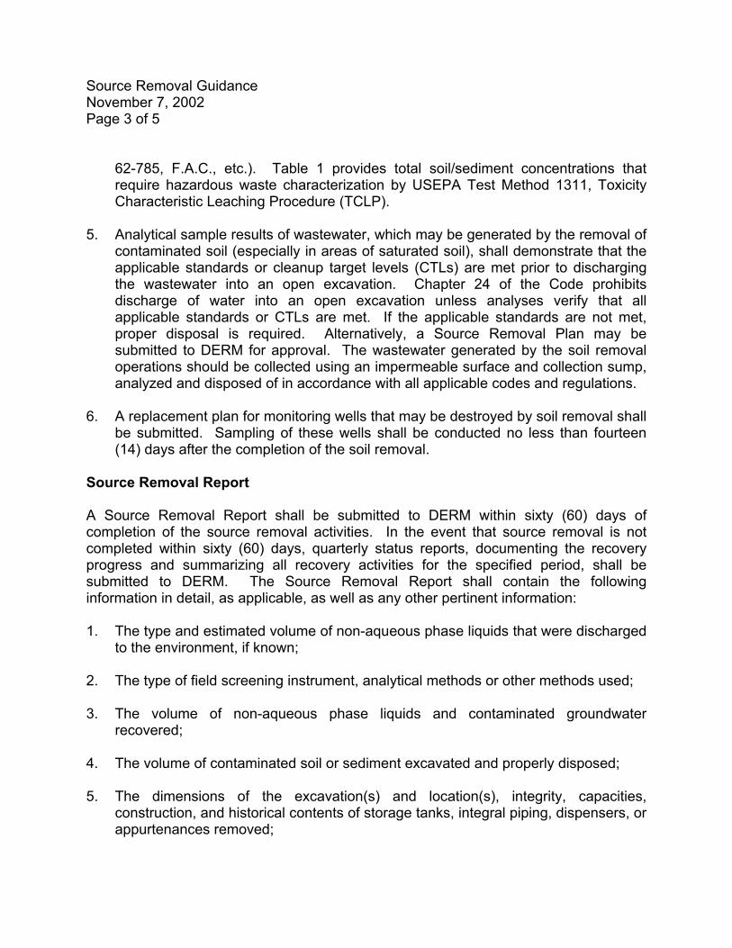
5. Analytical sample results of wastewater, which may be generated by the removal of
contaminated soil (especially in areas of saturated soil), shall demonstrate that the applicable standards or cleanup target levels (CTLs) are met prior to discharging the wastewater into an open excavation. Chapter 24 of the Code prohibits discharge of water into an open excavation unless analyses verify that all applicable standards or CTLs are met. If the applicable standards are not met, proper disposal is required. Alternatively, a Source Removal Plan may be submitted to DERM for approval. The wastewater generated by the soil removal operations should be collected using an impermeable surface and collection sump, analyzed and disposed of in accordance with all applicable codes and regulations.
6. A replacement plan for monitoring wells that may be destroyed by soil removal shall
be submitted. Sampling of these wells shall be conducted no less than fourteen (14) days after the completion of the soil removal.
Source Removal Report A Source Removal Report shall be submitted to DERM within sixty (60) days of completion of the source removal activities. In the event that source removal is not completed within sixty (60) days, quarterly status reports, documenting the recovery progress and summarizing all recovery activities for the specified period, shall be submitted to DERM. The Source Removal Report shall contain the following information in detail, as applicable, as well as any other pertinent information: 1. The type and estimated volume of non-aqueous phase liquids that were discharged
to the environment, if known; 2. The type of field screening instrument, analytical methods or other methods used; 3. The volume of non-aqueous phase liquids and contaminated groundwater
recovered; 4. The volume of contaminated soil or sediment excavated and properly disposed; 5. The dimensions of the excavation(s) and location(s), integrity, capacities,
construction, and historical contents of storage tanks, integral piping, dispensers, or appurtenances removed;
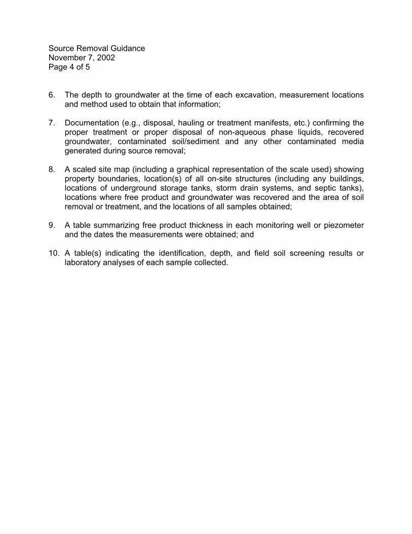
Source Removal Guidance November 7, 2002 Page 4 of 5 6. The depth to groundwater at the time of each excavation, measurement locations
and method used to obtain that information; 7. Documentation (e.g., disposal, hauling or treatment manifests, etc.) confirming the
proper treatment or proper disposal of non-aqueous phase liquids, recovered groundwater, contaminated soil/sediment and any other contaminated media generated during source removal;
8. A scaled site map (including a graphical representation of the scale used) showing
property boundaries, location(s) of all on-site structures (including any buildings, locations of underground storage tanks, storm drain systems, and septic tanks), locations where free product and groundwater was recovered and the area of soil removal or treatment, and the locations of all samples obtained;
9. A table summarizing free product thickness in each monitoring well or piezometer
and the dates the measurements were obtained; and 10. A table(s) indicating the identification, depth, and field soil screening results or
laboratory analyses of each sample collected.
Source Removal Guidance November 7, 2002 Page 5 of 5
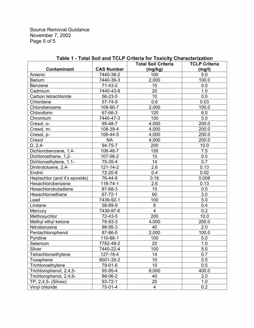
Table 1 - Total Soil and TCLP Criteria for Toxicity Characterization
Contaminant
CAS Number Total Soil Criteria
(mg/kg) TCLP Criteria
(mg/l) Arsenic 7440-38-2 100 5.0 Barium 7440-39-3 2,000 100.0 Benzene 71-43-2 10 0.5 Cadmium 7440-43-9 20 1.0 Carbon tetrachloride 56-23-5 10 0.5 Chlordane 57-74-9 0.6 0.03 Chlorobenzene 108-90-7 2,000 100.0 Chloroform 67-66-3 120 6.0 Chromium 7440-47-3 100 5.0 Cresol, o- 95-48-7 4,000 200.0 Cresol, m- 108-39-4 4,000 200.0 Cresol, p- 106-44-5 4,000 200.0 Cresol NA 4,000 200.0 D, 2,4- 94-75-7 200 10.0 Dichlorobenzene, 1,4- 106-46-7 150 7.5 Dichloroethane, 1,2- 107-06-2 10 0.5 Dichloroethylene, 1,1- 75-35-4 14 0.7 Dinitrotoluene, 2,4- 121-14-2 2.6 0.13 Endrin 72-20-8 0.4 0.02 Heptachlor (and it’s epoxide) 76-44-8 0.16 0.008 Hexachlorobenzene 118-74-1 2.6 0.13 Hexachlorobutadiene 87-68-3 10 0.5 Hexachloroethane 67-72-1 60 3.0 Lead 7439-92-1 100 5.0 Lindane 58-89-9 8 0.4 Mercury 7439-97-6 4 0.2 Methoxychlor 72-43-5 200 10.0 Methyl ethyl ketone 78-93-3 4,000 200.0 Nitrobenzene 98-95-3 40 2.0 Pentachlorophenol 87-86-5 2,000 100.0 Pyridine 110-86-1 100 5.0 Selenium 7782-49-2 20 1.0 Silver 7440-22-4 100 5.0 Tetrachloroethylene 127-18-4 14 0.7 Toxaphene 8001-35-2 10 0.5 Trichloroethylene 79-01-6 10 0.5 Trichlorophenol, 2,4,5- 95-95-4 8,000 400.0 Trichlorophenol, 2,4,6- 88-06-2 40 2.0 TP, 2,4,5- (Silvex) 93-72-1 20 1.0 Vinyl chloride 75-01-4 4 0.2
RBCA GUIDANCE No. 2
March 10, 2003POLLUTION REMEDIATION SECTION
SITE ASSESSMENT GUIDANCE FOR CONTAMINATED SITES REGULATED BY
SECTION 24-11.1(2), CODE OF MIAMI-DADE COUNTY This document provides general guidelines for implementing site assessment activities and for preparing the site assessment report (SAR). Applicability These guidelines are applicable to site assessments that are conducted in accordance with Section 24-11.1(2)(I)(4), Code of Miami-Dade County (“the Code”). Site Assessment Report One copy of the SAR, which may include information from previously submitted documents, shall be submitted by the responsible party in accordance with Section 24-11.1(2)(F), of the Code. In accordance with Section 24-11.1(2)(L) of the Code, the SAR shall be signed and sealed by a qualified Professional Engineer or Professional Geologist registered under Chapters 471 and 492, Florida Statutes (F.S.), respectively, certifying that the applicable portions of the SAR and associated work comply with standard professional practices and any other laws and rules governing the profession. Additionally, the company or business submitting the SAR must be registered as an engineering or geology business under Chapters 471 and 492, F.S., respectively. The SAR shall include the following sections, as applicable, as well as any other information that is pertinent to the assessment: 1. Facility and Discharge Information and Initial Abatement: This section shall provide
a site description, history of past and present operations (including those that involve the storage, treatment, use, disposal, processing or manufacturing of materials that may be potential contaminant sources), description of all products used or manufactured and all by-products and wastes (including water constituents) generated during the life of the facility, a summary of known spills or releases of materials, including permitted releases, that may be potential contaminant sources, a description of initial abatement or source removal activities, and a list of current permits.
Compiling the information above may involve the inspection of public records such as those at the local building department and DERM and the review of information such as historical land use records, Sanborne maps, and aerial photographs.
2. Background Site Assessment Information: This section shall provide a risk and receptor evaluation (e.g., potable and irrigation wells, surface water bodies, etc.), previous assessment information, and any previous remediation information.
Site Assessment Guidance March 10, 2003 Page 2 of 12
a.
Compiling the information above may involve inspection of public records (e.g.,
files located at DERM, the local Department of Health, the Water Management District, local municipalities, etc.) and performance of a field reconnaissance, as appropriate, to locate all water supply wells (e.g., potable, irrigation, industrial, etc.) and injection or drainage wells as defined in Chapter 62-528, Florida Administrative Code (F.A.C.). It may also involve review of information such as historical land use records, Sanborne maps and aerial photographs.
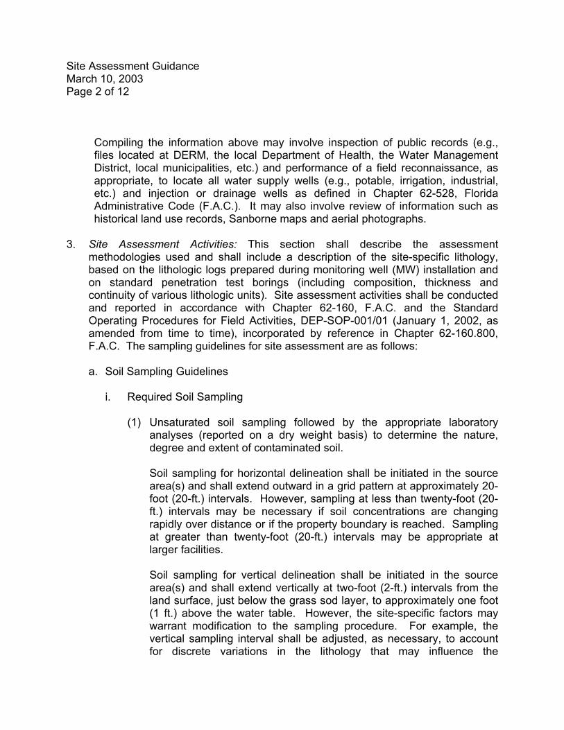
3. Site Assessment Activities: This section shall describe the assessment
methodologies used and shall include a description of the site-specific lithology, based on the lithologic logs prepared during monitoring well (MW) installation and on standard penetration test borings (including composition, thickness and continuity of various lithologic units). Site assessment activities shall be conducted and reported in accordance with Chapter 62-160, F.A.C. and the Standard Operating Procedures for Field Activities, DEP-SOP-001/01 (January 1, 2002, as amended from time to time), incorporated by reference in Chapter 62-160.800, F.A.C. The sampling guidelines for site assessment are as follows:
Soil Sampling Guidelines
i. Required Soil Sampling
(1) Unsaturated soil sampling followed by the appropriate laboratory
analyses (reported on a dry weight basis) to determine the nature, degree and extent of contaminated soil.
Soil sampling for horizontal delineation shall be initiated in the source area(s) and shall extend outward in a grid pattern at approximately 20-foot (20-ft.) intervals. However, sampling at less than twenty-foot (20-ft.) intervals may be necessary if soil concentrations are changing rapidly over distance or if the property boundary is reached. Sampling at greater than twenty-foot (20-ft.) intervals may be appropriate at larger facilities. Soil sampling for vertical delineation shall be initiated in the source area(s) and shall extend vertically at two-foot (2-ft.) intervals from the land surface, just below the grass sod layer, to approximately one foot (1 ft.) above the water table. However, the site-specific factors may warrant modification to the sampling procedure. For example, the vertical sampling interval shall be adjusted, as necessary, to account for discrete variations in the lithology that may influence the
Site Assessment Guidance March 10, 2003 Page 3 of 12
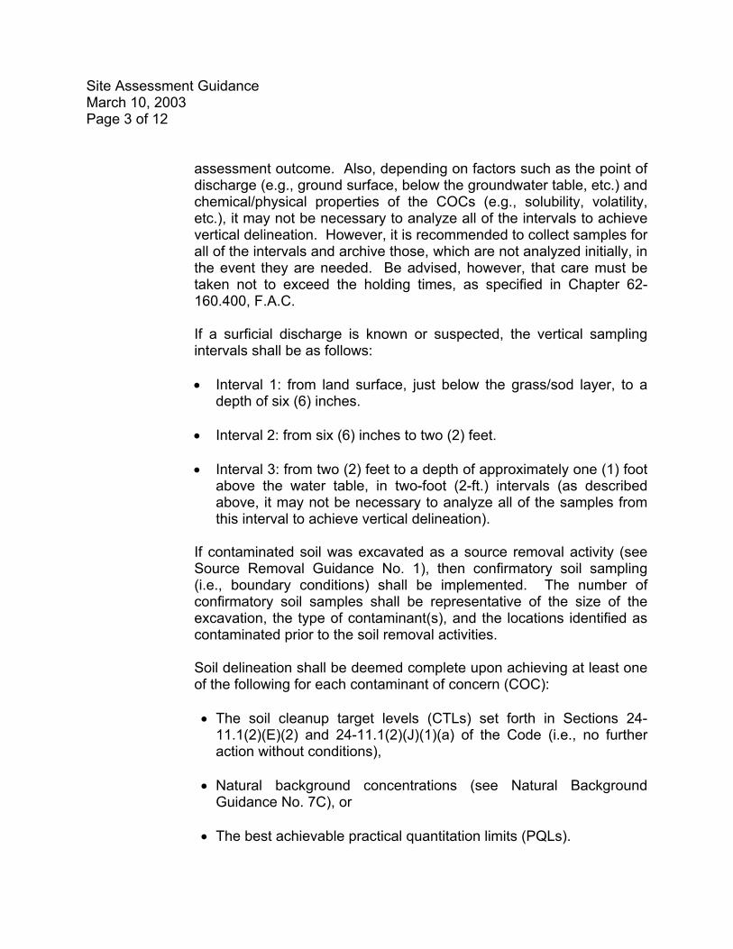
assessment outcome. Also, depending on factors such as the point of discharge (e.g., ground surface, below the groundwater table, etc.) and chemical/physical properties of the COCs (e.g., solubility, volatility, etc.), it may not be necessary to analyze all of the intervals to achieve vertical delineation. However, it is recommended to collect samples for all of the intervals and archive those, which are not analyzed initially, in the event they are needed. Be advised, however, that care must be taken not to exceed the holding times, as specified in Chapter 62-160.400, F.A.C.
If a surficial discharge is known or suspected, the vertical sampling intervals shall be as follows:
• Interval 1: from land surface, just below the grass/sod layer, to a
depth of six (6) inches. • Interval 2: from six (6) inches to two (2) feet. • Interval 3: from two (2) feet to a depth of approximately one (1) foot
above the water table, in two-foot (2-ft.) intervals (as described above, it may not be necessary to analyze all of the samples from this interval to achieve vertical delineation).
If contaminated soil was excavated as a source removal activity (see Source Removal Guidance No. 1), then confirmatory soil sampling (i.e., boundary conditions) shall be implemented. The number of confirmatory soil samples shall be representative of the size of the excavation, the type of contaminant(s), and the locations identified as contaminated prior to the soil removal activities. Soil delineation shall be deemed complete upon achieving at least one of the following for each contaminant of concern (COC):
• The soil cleanup target levels (CTLs) set forth in Sections 24-
11.1(2)(E)(2) and 24-11.1(2)(J)(1)(a) of the Code (i.e., no further action without conditions),
• Natural background concentrations (see Natural Background
Guidance No. 7C), or • The best achievable practical quantitation limits (PQLs).
Site Assessment Guidance March 10, 2003 Page 4 of 12
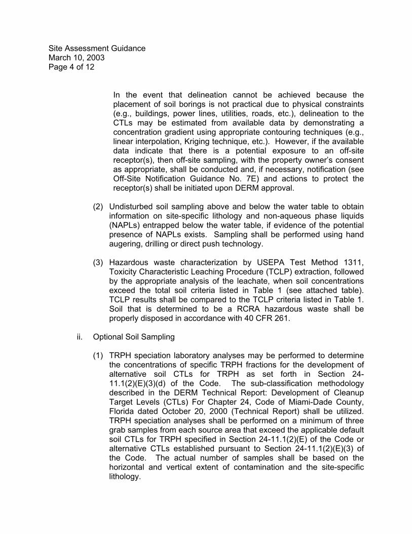
In the event that delineation cannot be achieved because the placement of soil borings is not practical due to physical constraints (e.g., buildings, power lines, utilities, roads, etc.), delineation to the CTLs may be estimated from available data by demonstrating a concentration gradient using appropriate contouring techniques (e.g., linear interpolation, Kriging technique, etc.). However, if the available data indicate that there is a potential exposure to an off-site receptor(s), then off-site sampling, with the property owner’s consent as appropriate, shall be conducted and, if necessary, notification (see Off-Site Notification Guidance No. 7E) and actions to protect the receptor(s) shall be initiated upon DERM approval.
(2) Undisturbed soil sampling above and below the water table to obtain
information on site-specific lithology and non-aqueous phase liquids (NAPLs) entrapped below the water table, if evidence of the potential presence of NAPLs exists. Sampling shall be performed using hand augering, drilling or direct push technology.
(3) Hazardous waste characterization by USEPA Test Method 1311,
Toxicity Characteristic Leaching Procedure (TCLP) extraction, followed by the appropriate analysis of the leachate, when soil concentrations exceed the total soil criteria listed in Table 1 (see attached table). TCLP results shall be compared to the TCLP criteria listed in Table 1. Soil that is determined to be a RCRA hazardous waste shall be properly disposed in accordance with 40 CFR 261.
ii. Optional Soil Sampling
(1) TRPH speciation laboratory analyses may be performed to determine
the concentrations of specific TRPH fractions for the development of alternative soil CTLs for TRPH as set forth in Section 24-11.1(2)(E)(3)(d) of the Code. The sub-classification methodology described in the DERM Technical Report: Development of Cleanup Target Levels (CTLs) For Chapter 24, Code of Miami-Dade County, Florida dated October 20, 2000 (Technical Report) shall be utilized. TRPH speciation analyses shall be performed on a minimum of three grab samples from each source area that exceed the applicable default soil CTLs for TRPH specified in Section 24-11.1(2)(E) of the Code or alternative CTLs established pursuant to Section 24-11.1(2)(E)(3) of the Code. The actual number of samples shall be based on the horizontal and vertical extent of contamination and the site-specific lithology.
Site Assessment Guidance March 10, 2003 Page 5 of 12
b.
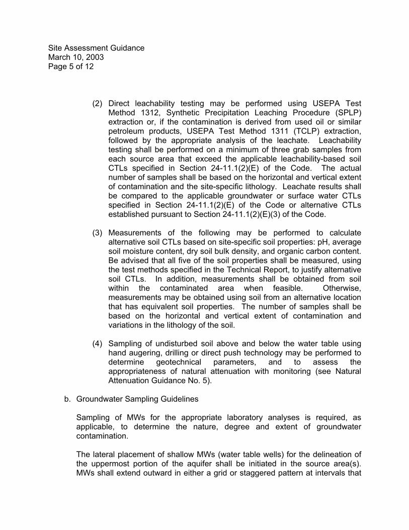
(2) Direct leachability testing may be performed using USEPA Test
Method 1312, Synthetic Precipitation Leaching Procedure (SPLP) extraction or, if the contamination is derived from used oil or similar petroleum products, USEPA Test Method 1311 (TCLP) extraction, followed by the appropriate analysis of the leachate. Leachability testing shall be performed on a minimum of three grab samples from each source area that exceed the applicable leachability-based soil CTLs specified in Section 24-11.1(2)(E) of the Code. The actual number of samples shall be based on the horizontal and vertical extent of contamination and the site-specific lithology. Leachate results shall be compared to the applicable groundwater or surface water CTLs specified in Section 24-11.1(2)(E) of the Code or alternative CTLs established pursuant to Section 24-11.1(2)(E)(3) of the Code.
(3) Measurements of the following may be performed to calculate
alternative soil CTLs based on site-specific soil properties: pH, average soil moisture content, dry soil bulk density, and organic carbon content. Be advised that all five of the soil properties shall be measured, using the test methods specified in the Technical Report, to justify alternative soil CTLs. In addition, measurements shall be obtained from soil within the contaminated area when feasible. Otherwise, measurements may be obtained using soil from an alternative location that has equivalent soil properties. The number of samples shall be based on the horizontal and vertical extent of contamination and variations in the lithology of the soil.
(4) Sampling of undisturbed soil above and below the water table using
hand augering, drilling or direct push technology may be performed to determine geotechnical parameters, and to assess the appropriateness of natural attenuation with monitoring (see Natural Attenuation Guidance No. 5).
Groundwater Sampling Guidelines
Sampling of MWs for the appropriate laboratory analyses is required, as applicable, to determine the nature, degree and extent of groundwater contamination. The lateral placement of shallow MWs (water table wells) for the delineation of the uppermost portion of the aquifer shall be initiated in the source area(s). MWs shall extend outward in either a grid or staggered pattern at intervals that
Site Assessment Guidance March 10, 2003 Page 6 of 12
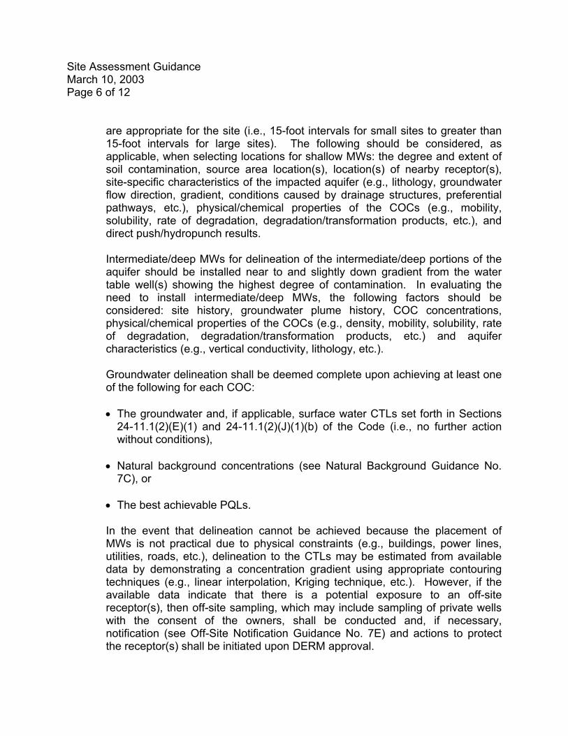
are appropriate for the site (i.e., 15-foot intervals for small sites to greater than 15-foot intervals for large sites). The following should be considered, as applicable, when selecting locations for shallow MWs: the degree and extent of soil contamination, source area location(s), location(s) of nearby receptor(s), site-specific characteristics of the impacted aquifer (e.g., lithology, groundwater flow direction, gradient, conditions caused by drainage structures, preferential pathways, etc.), physical/chemical properties of the COCs (e.g., mobility, solubility, rate of degradation, degradation/transformation products, etc.), and direct push/hydropunch results.
Intermediate/deep MWs for delineation of the intermediate/deep portions of the aquifer should be installed near to and slightly down gradient from the water table well(s) showing the highest degree of contamination. In evaluating the need to install intermediate/deep MWs, the following factors should be considered: site history, groundwater plume history, COC concentrations, physical/chemical properties of the COCs (e.g., density, mobility, solubility, rate of degradation, degradation/transformation products, etc.) and aquifer characteristics (e.g., vertical conductivity, lithology, etc.). Groundwater delineation shall be deemed complete upon achieving at least one of the following for each COC:
• The groundwater and, if applicable, surface water CTLs set forth in Sections
24-11.1(2)(E)(1) and 24-11.1(2)(J)(1)(b) of the Code (i.e., no further action without conditions),
• Natural background concentrations (see Natural Background Guidance No.
7C), or • The best achievable PQLs.
In the event that delineation cannot be achieved because the placement of MWs is not practical due to physical constraints (e.g., buildings, power lines, utilities, roads, etc.), delineation to the CTLs may be estimated from available data by demonstrating a concentration gradient using appropriate contouring techniques (e.g., linear interpolation, Kriging technique, etc.). However, if the available data indicate that there is a potential exposure to an off-site receptor(s), then off-site sampling, which may include sampling of private wells with the consent of the owners, shall be conducted and, if necessary, notification (see Off-Site Notification Guidance No. 7E) and actions to protect the receptor(s) shall be initiated upon DERM approval.
Site Assessment Guidance March 10, 2003 Page 7 of 12
c.
d.
a.
Surface/Sediment Sampling Guidelines
If surface waters are, or are reasonably expected to be, affected by either a direct discharge or by migration of contaminated groundwater (as demonstrated using groundwater MW data, groundwater flow rate and direction, or fate and transport modeling data), sampling and appropriate laboratory analyses of surface water and sediment (reported on a dry weight basis) is required to determine the nature, degree and extent of contamination. Surface water and sediment samples shall be collected nearest to, and downstream of, the point of entry of the COCs.
Contaminated Waste Disposal Guidelines
Drill cuttings, drilling mud, development water and purge water generated during MW installation, and any other contaminated waste generated during the assessment activities, shall be handled and disposed of in such a manner that contamination is not spread into previously uncontaminated or less contaminated media or areas. This guidance document does not relieve the responsible party from the obligation to comply with other applicable regulations for handling and disposing of contaminated media (e.g., 40 CFR 261, 40 CFR 761, Chapter 62-701, F.A.C., Chapter 62-730, F.A.C., Chapter 62-770, F.A.C., Chapter 62-782, F.A.C., Chapter 62-785, F.A.C., etc.).
4. Impacted Media: This section shall provide the results of the soil, groundwater,
surface water, sediment, and free product investigations and shall compare the results to the applicable criteria (e.g., CTLs, etc.) set forth in Section 24-11.1(2) of the Code. Site concentrations shall be compared to the applicable criteria on a point-by-point basis. However, if the direct exposure soil CTLs are exceeded, then calculation of the 95% upper confidence limit of the arithmetic mean (95% UCL) may be considered for comparison to the direct exposure soil CTLs (see 95% UCL Guidance No. 7B).
Be advised that in the event that contamination originating from the site extends beyond the property boundaries, off-site notification (see Off-Site Notification Guidance No. 7E) shall be provided in accordance with Section 24-11.1(2)(I)(2) of the Code.
5. Figures: All maps shall be drawn to scale, indicate the North direction, and include
a graphical representation of the scale used.
The following maps shall be included in all SARs:
Site Assessment Guidance March 10, 2003 Page 8 of 12
b.
i. Site map(s) showing all pertinent surface and subsurface features such as
utilities, current and past above and underground structures, current and past storage areas, local drainage features, natural or man-made structures that may influence mounding or plume migration, existing land cover, contaminant discharge location(s), sources of contamination, and source removal areas.
ii. A well location map showing the location(s) of all on-site supply wells (e.g.,
potable, irrigation, industrial, etc.). iii. Site map(s) showing all historical soil sampling locations for field screening
or laboratory analyses and illustrating the horizontal and vertical extent of vadose zone soil contamination.
iv. Site map(s) showing all historical sediment sampling locations and
illustrating the degree and extent of contamination. v. A site map showing the estimated horizontal extent of free product, if
present. vi. Site map(s) showing all historical groundwater and surface water sampling
locations and contours, and illustrating the degree and extent of groundwater and surface water contamination (including monitoring well locations and corresponding analytical data).
vii. At least two cross-sections per medium illustrating the site-specific lithology
and approximate COC concentrations.
viii. Site map(s) illustrating the water-level elevations (calculated from a minimum of two measurements obtained at least one month apart) for each MW, piezometer, and staff gauge where surface water is a concern, and depicting the estimated elevation contours and interpretation of groundwater flow direction. If different strata of the same aquifer, or if different aquifers are affected, separate figures shall be submitted for each date on which measurements were recorded, depicting flow in each stratum or aquifer. If the site’s groundwater is tidally-influenced, separate figures shall be submitted depicting flow at high and low tide.
The following additional maps shall be included, unless the site qualifies for site closure in accordance with Section 24-11.1(2)(J) of the Code (i.e., no further action or no further action with conditions):
Site Assessment Guidance March 10, 2003 Page 9 of 12
a.
b.
c.
d.
e.
f.
i. A copy of the portion of the most recent USGS topographic map, including
quadrangle name, which clearly identifies the site in relation to the surrounding area.
ii. A vicinity map showing pertinent features, such as land uses and property
boundaries.
iii. A well location map showing the approximate location(s) of all municipal/public wells and private supply well(s) (e.g., potable, irrigation, industrial, etc.) identified within ½ mile and ¼ mile, respectively, of the subject site.
6. Tables: The following shall be included in the SAR, as applicable:
A table summarizing all MW (including storage tank compliance wells or other compliance wells required by permit), piezometer, and recovery well construction details (including the top-of-casing elevation referenced to National Geodetic Vertical Datum (NGVD) of 1929 or North American Vertical Datum of 1988 (NAVD88), depth of the top of the screen below land surface, total depth and screen length, and ground surface elevation referenced to NGVD of 1929 or NAVD88). The table shall be updated each time additional MWs, piezometers, or recovery wells are installed.
Construction diagrams, including methods, materials, and lithologic logs.
Groundwater sampling log, including development/purging data, field sampling data, and volumes of groundwater removed during well development/purging (see FDEP SOPs for Field Activities, DEP-SOP-001/01 (January 1, 2002, as amended from time to time), FS 2200 Groundwater Sampling for a groundwater sampling log template).
Tables listing the top-of-casing elevations surveyed to the NGVD of 1929 or to the NAVD88, depths to groundwater, water-level elevations obtained at least twice, at least one month apart, and the dates the data were collected.
A table summarizing the capacity, use and well construction details, if available, of all the water supply wells identified during the well survey.
Table(s) summarizing the field screening and laboratory analytical results obtained at each soil sampling location and depth, sampling/analysis date(s), detection limits (i.e., method detection limits, MDLs, and PQLs), and method
Site Assessment Guidance March 10, 2003 Page 10 of 12
g.
h.
i.
a.
b.
c.
numbers for extraction/analyses performed (listing all contaminants detected and their corresponding CTLs).
Table(s) summarizing the laboratory analytical results obtained at each sediment sampling location, sampling/analyses date(s), detection limits (i.e., method detection limits, MDLs, and PQLs), and method numbers for extraction/analyses performed (listing all contaminants detected and their corresponding CTLs).
A current table that summarizes free product thickness measured, volumes recovered, and date(s) measurements were recorded, if applicable.
Table(s) summarizing the groundwater and surface water analytical results (with the most recent sampling of representative MWs having occurred within 270 days of the SAR submittal), sampling/analysis date(s), detection limits (i.e., MDLs and PQLs), and method numbers for extraction/analyses performed (listing all contaminants detected and their corresponding CTLs).
7. Calculations: The following calculations shall be included in the SAR, as applicable:
Data and calculations used to determine the top-of-casing elevations and the accuracy of the survey performed.
Pumping test results (to determine aquifer properties in all impacted strata of the aquifer), including a description of methods used, assumptions made, field data and calculations, unless 1) groundwater extraction is proposed, in which case the pumping test may be deferred until the Remedial Action Plan phase (see Active Remediation Guidance No. 4), or 2) the site meets the No Further Action criteria in Section 24-11.1(2)(J) of the Code.
The results of the calculation of horizontal groundwater flow velocity (v) for all impacted strata of the aquifer (using the formula v=KI/n, where K = average hydraulic conductivity, I = average hydraulic gradient, and n = estimated effective soil porosity), unless 1) a monitoring only plan for natural attenuation is proposed, in which case the calculation of groundwater velocity may be deferred until the monitoring only plan phase (see Natural Attenuation Guidance No. 5), or 2) the site meets the No Further Action criteria in Section 24-11.1(2)(J) of the Code.
8. Laboratory Data Sheets and Quality Assurance: The SAR shall include all
information required by Section 24-11.1(2)(M) of the Code, such as the original laboratory reports from a certified laboratory that include all information required in
Site Assessment Guidance March 10, 2003 Page 11 of 12
a.
b.
c.
d.
e.
Chapter 62-160, F.A.C., copies of the completed chain of custody records, copies of the completed water sampling log forms, and results from screening tests or on-site analyses.
9. Other: Any other information that is deemed relevant to the site assessment. 10. Recommendations: This section shall summarize the site assessment results and
shall include one of the following:
A no further action proposal (i.e., closure without institutional or engineering controls) if the site meets the applicable criteria in Section 24-11.1(2)(J)(1) of the Code,
A no further action with conditions proposal (i.e., closure with institutional and, if applicable, engineering controls) if the site meets the applicable criteria in Section 24-11.1(2)(J)(2) of the Code,
A recommendation to implement a monitoring only plan for natural attenuation in accordance with Section 24-11.1(2)(K)(1) of the Code (see Natural Attenuation Guidance No. 5),
A recommendation to prepare a risk assessment in accordance with Section 24-11.1(2)(K)(2) of the Code (see Risk Assessment Guidance No. 6), or
A recommendation to prepare a remedial action plan in accordance with Section 24-11.1(2)(K)(3) of the Code (see Active Remediation Guidance No. 4).
Site Assessment Guidance March 10, 2003 Page 12 of 12
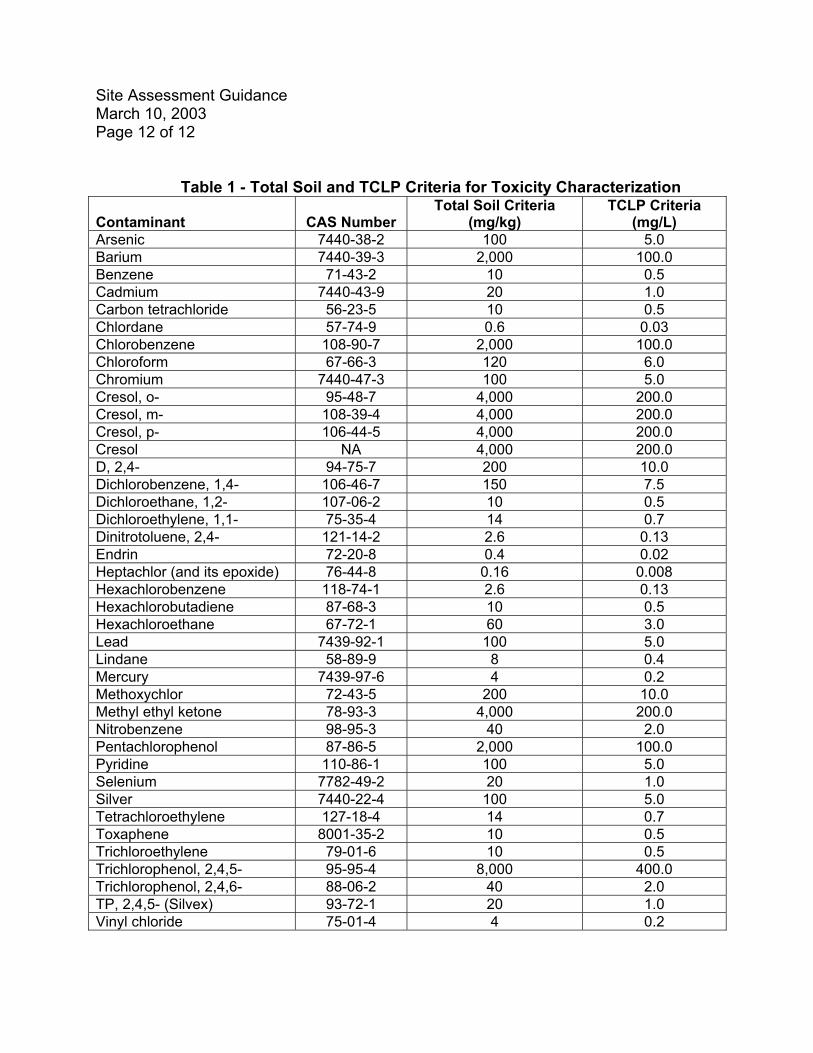
Table 1 - Total Soil and TCLP Criteria for Toxicity Characterization Contaminant
CAS Number
Total Soil Criteria (mg/kg)
TCLP Criteria (mg/L)
Arsenic 7440-38-2 100 5.0 Barium 7440-39-3 2,000 100.0 Benzene 71-43-2 10 0.5 Cadmium 7440-43-9 20 1.0 Carbon tetrachloride 56-23-5 10 0.5 Chlordane 57-74-9 0.6 0.03 Chlorobenzene 108-90-7 2,000 100.0 Chloroform 67-66-3 120 6.0 Chromium 7440-47-3 100 5.0 Cresol, o- 95-48-7 4,000 200.0 Cresol, m- 108-39-4 4,000 200.0 Cresol, p- 106-44-5 4,000 200.0 Cresol NA 4,000 200.0 D, 2,4- 94-75-7 200 10.0 Dichlorobenzene, 1,4- 106-46-7 150 7.5 Dichloroethane, 1,2- 107-06-2 10 0.5 Dichloroethylene, 1,1- 75-35-4 14 0.7 Dinitrotoluene, 2,4- 121-14-2 2.6 0.13 Endrin 72-20-8 0.4 0.02 Heptachlor (and its epoxide) 76-44-8 0.16 0.008 Hexachlorobenzene 118-74-1 2.6 0.13 Hexachlorobutadiene 87-68-3 10 0.5 Hexachloroethane 67-72-1 60 3.0 Lead 7439-92-1 100 5.0 Lindane 58-89-9 8 0.4 Mercury 7439-97-6 4 0.2 Methoxychlor 72-43-5 200 10.0 Methyl ethyl ketone 78-93-3 4,000 200.0 Nitrobenzene 98-95-3 40 2.0 Pentachlorophenol 87-86-5 2,000 100.0 Pyridine 110-86-1 100 5.0 Selenium 7782-49-2 20 1.0 Silver 7440-22-4 100 5.0 Tetrachloroethylene 127-18-4 14 0.7 Toxaphene 8001-35-2 10 0.5 Trichloroethylene 79-01-6 10 0.5 Trichlorophenol, 2,4,5- 95-95-4 8,000 400.0 Trichlorophenol, 2,4,6- 88-06-2 40 2.0 TP, 2,4,5- (Silvex) 93-72-1 20 1.0 Vinyl chloride 75-01-4 4 0.2

RBCA GUIDANCE No. 3
November 14, 2002POLLUTION REMEDIATION SECTION
RISK MANAGEMENT OPTIONS GUIDANCE FOR CONTAMINATED SITES REGULATED BY SECTION 24-11.1(2), CODE OF MIAMI-DADE COUNTY
This document provides general guidelines for evaluating the risk management options available for achieving site closure in the form of a no further action or no further action with conditions. Applicability These guidelines apply to contaminated site cleanups that are conducted in accordance with Section 24-11.1(2), Code of Miami-Dade County (“the Code”). Risk Management Options 1. Level I: A no further action (NFA) without institutional or engineering controls shall
apply if it is demonstrated to the satisfaction of DERM that the following conditions are met:
a.
b.
Free product does not exist and no fire or explosion hazard exists,
Contaminated soil is not present in the unsaturated zone, as demonstrated by the analyses of soil samples collected from representative sampling locations (see Site Assessment Guidance No. 2) that show that one or more of the options for direct exposure and one or more of the options for leachability are achieved, as appropriate:
i. Direct Exposure Options1:
(1) Option IA: Concentrations of the contaminants of concern (COCs) do not
exceed 1) the apportioned2 default residential direct exposure soil cleanup target levels (CTLs), 2) natural background concentrations or 3) the practical quantitation limits (PQLs). The CTLs are specified in Table 2, Section 24-11.1(2)(E)(5)(b) of the Code or developed in accordance with Section 24-11.1(2)(E)(5)(c) of the Code. Natural background concentrations shall be obtained from the Miami-Dade County Natural Background Study for Soil, dated February 8, 2002 (see Attachment E) or established in a site-specific background study approved by DERM (see Natural Background Guidance No. 7C). The PQLs shall be those specified in the Quality Manual for the State of Florida Department of Environmental Protection Central Chemistry Laboratory (CQAP #870688G, November 2000, or most recent update).
Risk Management Options Guidance November 14, 2002 Page 2 of 17
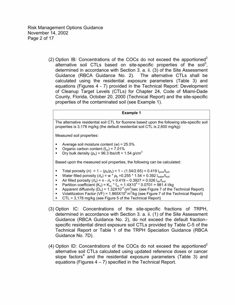
(2) Option IB: Concentrations of the COCs do not exceed the apportioned2
alternative soil CTLs based on site-specific properties of the soil3, determined in accordance with Section 3. a. ii. (3) of the Site Assessment Guidance (RBCA Guidance No. 2). The alternative CTLs shall be calculated using the residential exposure parameters (Table 3) and equations (Figures 4 - 7) provided in the Technical Report: Development of Cleanup Target Levels (CTLs) for Chapter 24, Code of Miami-Dade County, Florida, October 20, 2000 (Technical Report) and the site-specific properties of the contaminated soil (see Example 1).
Example 1
The alternative residential soil CTL for fluorene based upon the following site-specific soil properties is 3,178 mg/kg (the default residential soil CTL is 2,600 mg/kg): Measured soil properties: Average soil moisture content (w) = 25.5% Organic carbon content (foc) = 7.01% Dry bulk density (pb) = 96.3 lbs/cft = 1.54 g/cm3
Based upon the measured soil properties, the following can be calculated: Total porosity (n) = 1 – (pb/ps) = 1 – (1.54/2.65) = 0.419 lpore/lsoil Water filled porosity (θw) = w * pb =0.255 * 1.54 = 0.392 lwater/lsoil Air filled porosity (θa) = n - θw = 0.419 – 0.3927 = 0.026 lair/lsoil Partition coefficient (Kd) = Koc * foc = 1.4X104 * 0.0701 = 981.4 l/kg Apparent diffusivity (DA) = 1.32X10⁻⁹ cm2/sec (see Figure 7 of the Technical Report) Volatilization Factor (VF) = 1.865X10⁶ m3/kg (see Figure 7 of the Technical Report) CTL = 3,178 mg/kg (see Figure 5 of the Technical Report)
(3) Option IC: Concentrations of the site-specific fractions of TRPH,
determined in accordance with Section 3. a. ii. (1) of the Site Assessment Guidance (RBCA Guidance No. 2), do not exceed the default fraction–specific residential direct exposure soil CTLs provided by Table C-5 of the Technical Report or Table 1 of the TRPH Speciation Guidance (RBCA Guidance No. 7D).
(4) Option ID: Concentrations of the COCs do not exceed the apportioned2
alternative soil CTLs calculated using updated reference doses or cancer slope factors4 and the residential exposure parameters (Table 3) and equations (Figures 4 – 7) specified in the Technical Report.
Risk Management Options Guidance November 14, 2002 Page 3 of 17
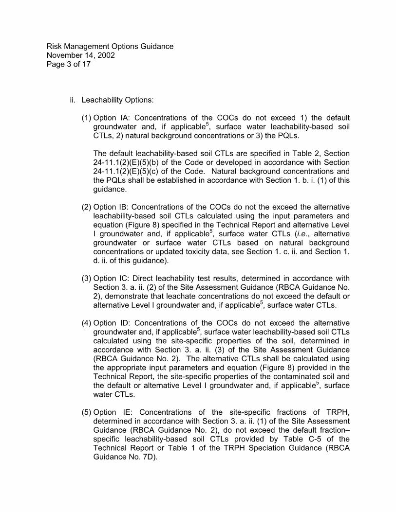
ii. Leachability Options:
(1) Option IA: Concentrations of the COCs do not exceed 1) the default groundwater and, if applicable5, surface water leachability-based soil CTLs, 2) natural background concentrations or 3) the PQLs. The default leachability-based soil CTLs are specified in Table 2, Section 24-11.1(2)(E)(5)(b) of the Code or developed in accordance with Section 24-11.1(2)(E)(5)(c) of the Code. Natural background concentrations and the PQLs shall be established in accordance with Section 1. b. i. (1) of this guidance.
(2) Option IB: Concentrations of the COCs do not the exceed the alternative
leachability-based soil CTLs calculated using the input parameters and equation (Figure 8) specified in the Technical Report and alternative Level I groundwater and, if applicable5, surface water CTLs (i.e., alternative groundwater or surface water CTLs based on natural background concentrations or updated toxicity data, see Section 1. c. ii. and Section 1. d. ii. of this guidance).
(3) Option IC: Direct leachability test results, determined in accordance with
Section 3. a. ii. (2) of the Site Assessment Guidance (RBCA Guidance No. 2), demonstrate that leachate concentrations do not exceed the default or alternative Level I groundwater and, if applicable5, surface water CTLs.
(4) Option ID: Concentrations of the COCs do not exceed the alternative
groundwater and, if applicable5, surface water leachability-based soil CTLs calculated using the site-specific properties of the soil, determined in accordance with Section 3. a. ii. (3) of the Site Assessment Guidance (RBCA Guidance No. 2). The alternative CTLs shall be calculated using the appropriate input parameters and equation (Figure 8) provided in the Technical Report, the site-specific properties of the contaminated soil and the default or alternative Level I groundwater and, if applicable5, surface water CTLs.
(5) Option IE: Concentrations of the site-specific fractions of TRPH,
determined in accordance with Section 3. a. ii. (1) of the Site Assessment Guidance (RBCA Guidance No. 2), do not exceed the default fraction–specific leachability-based soil CTLs provided by Table C-5 of the Technical Report or Table 1 of the TRPH Speciation Guidance (RBCA Guidance No. 7D).
Risk Management Options Guidance November 14, 2002 Page 4 of 17
c.
d.
Contaminated groundwater is not present, as demonstrated by the analyses of groundwater samples collected from representative sampling locations that show that one or both of the following options are achieved, as appropriate:
i. Option IA: Concentrations of the COCs do not exceed 1) the default
apportioned2 groundwater and, if applicable5, surface water CTLs, 2) natural background concentrations or 3) the PQLs. The groundwater and surface water CTLs are specified in Table 1, Section 24-11.1(2)(E)(5)(a) of the Code or developed in accordance with Section 24-11.1(2)(E)(5)(c) of the Code. Natural background concentrations and the PQLs shall be established in accordance with Section 1. b. i. (1) of this guidance.
ii. Option IB6: Concentrations of the COCs do not exceed the apportioned2
alternative groundwater and, if applicable5, surface water CTLs calculated using updated reference doses or cancer slope factors4 and the input parameters and equations (Figures 1, 2 and 3B) specified in the Technical Report.
Contaminated surface water is not present, as demonstrated by the analyses of surface water samples collected from representative sampling locations that show that one or both of the following options are achieved, as appropriate:
i. Option IA: Concentrations of the COCs do not exceed 1) the default and,
where appropriate, apportioned2 fresh or marine surface water CTLs, 2) natural background concentrations or 3) the PQLs.
The surface water CTLs are specified in Table 1, Section 24-11.1(2)(E)(5)(a) of the Code or developed in accordance with Section 24-11.1(2)(E)(5)(c) of the Code. Natural background concentrations shall be established in a site-specific background study approved by DERM. The PQLs shall be established in accordance with Section 1. b. i. (1) of this guidance.
ii. Option IB6: Concentrations of the COCs do not exceed the alternative surface
water CTLs calculated using updated reference doses or cancer slope factors4 and the input parameters and equation (Figure 3B) specified in the Technical Report. Documentation shall be provided which demonstrates that the alternative human health-based surface water CTLs do not exceed the appropriate surface water CTLs based upon the protection of aquatic life.
Risk Management Options Guidance November 14, 2002 Page 5 of 17
e.
a.
b.
Contaminated sediment is not present, as demonstrated by the analyses of sediment samples collected from representative sampling locations, that show that 1) the COCs are not present in concentrations that are reasonably expected to be injurious to humans, plants, animals, fish or other aquatic life, or property, or 2) concentrations of the COCs do not exceed natural background concentrations.
The demonstration that contaminated sediment does not exist may be based on the Threshold Limit Values specified in the Florida Department of Environmental Protection guideline “Approach to the Assessment of Sediment Quality in Florida Coastal Waters” (November 1994), site-specific bioassays, a site-specific risk assessment, a site-specific natural background study approved by DERM, or a combination thereof.
2. Level II: A no further action with institutional and, if appropriate, engineering controls
shall apply if the controls are protective of human health, public safety and the environment and are elected by the property owner. Fate and transport models, supported by a minimum of one year of monitoring, may be utilized to validate the no further action with conditions proposal. The Level II CTLs apply only within the real property boundaries; it shall be demonstrated, based on sampling results and, if appropriate, fate and transport modeling, that concentrations at the property boundary do not, and will not, exceed the Level I CTLs. It shall be demonstrated to the satisfaction of DERM that the following conditions are met:
Free product does not exist, unless it is demonstrated through an approved feasibility study that removal is not technologically feasible, and no fire or explosion hazard exists.
Alternative soil CTLs have been established by the real property owner and one or more of the options for direct exposure and one or more of the options for leachability are achieved, as appropriate:
i. Direct Exposure Options1:
(1) Option IIA: Concentrations of the COCs do not exceed the apportioned2
default commercial/industrial direct exposure soil CTLs specified in Table 2, Section 24-11.1(2)(E)(5)(b) of the Code or developed in accordance with Section 24-11.1(2)(E)(5)(c) of the Code.
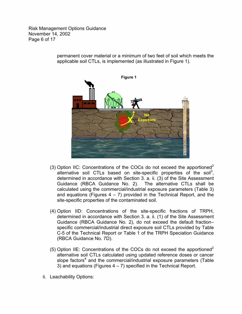
(2) Option IIB: Concentrations of the COCs may exceed the direct exposure
soil CTLs if an engineering control that prevents human exposure, such as
Risk Management Options Guidance November 14, 2002 Page 6 of 17
permanent cover material or a minimum of two feet of soil which meets the applicable soil CTLs, is implemented (as illustrated in Figure 1).
Figure 1
XNo
Exposure
(3) Option IIC: Concentrations of the COCs do not exceed the apportioned2 alternative soil CTLs based on site-specific properties of the soil3, determined in accordance with Section 3. a. ii. (3) of the Site Assessment Guidance (RBCA Guidance No. 2). The alternative CTLs shall be calculated using the commercial/industrial exposure parameters (Table 3) and equations (Figures 4 – 7) provided in the Technical Report, and the site-specific properties of the contaminated soil.
(4) Option IID: Concentrations of the site-specific fractions of TRPH,
determined in accordance with Section 3. a. ii. (1) of the Site Assessment Guidance (RBCA Guidance No. 2), do not exceed the default fraction–specific commercial/industrial direct exposure soil CTLs provided by Table C-5 of the Technical Report or Table 1 of the TRPH Speciation Guidance (RBCA Guidance No. 7D).
(5) Option IIE: Concentrations of the COCs do not exceed the apportioned2
alternative soil CTLs calculated using updated reference doses or cancer slope factors4 and the commercial/industrial exposure parameters (Table 3) and equations (Figures 4 – 7) specified in the Technical Report.
ii. Leachability Options:
Risk Management Options Guidance November 14, 2002 Page 7 of 17
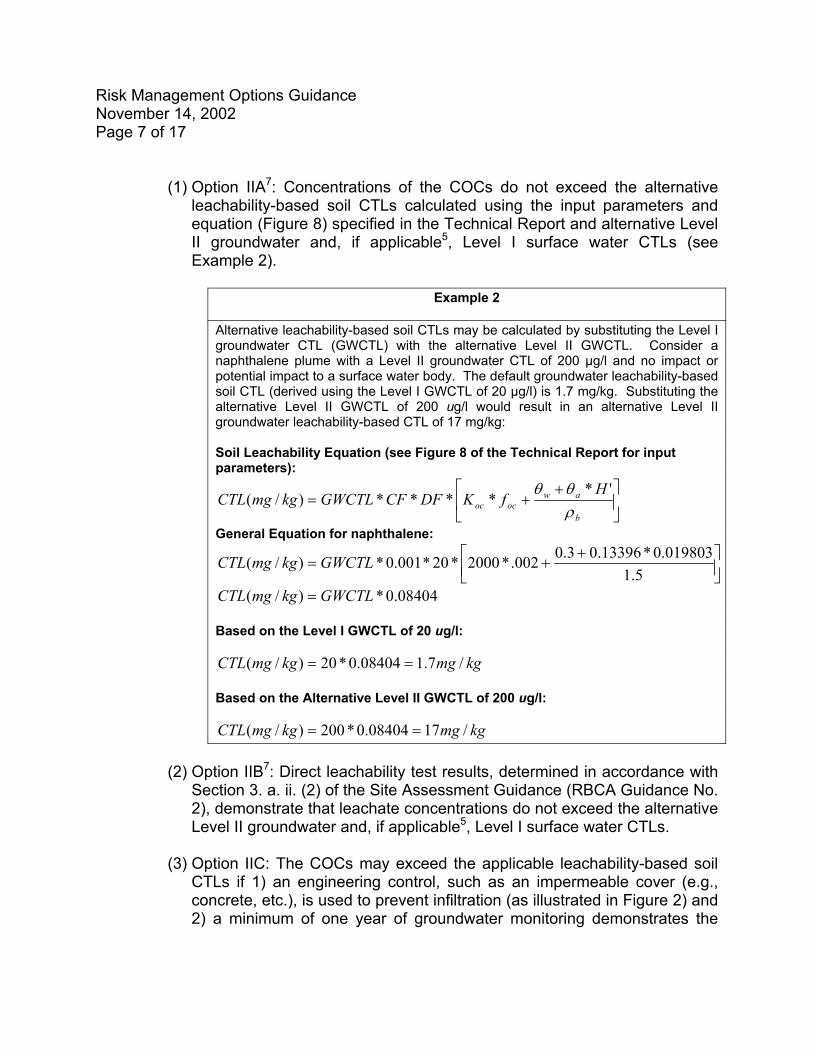
(1) Option IIA7: Concentrations of the COCs do not exceed the alternative leachability-based soil CTLs calculated using the input parameters and equation (Figure 8) specified in the Technical Report and alternative Level II groundwater and, if applicable5, Level I surface water CTLs (see Example 2).
Example 2
Alternative leachability-based soil CTLs may be calculated by substituting the Level I groundwater CTL (GWCTL) with the alternative Level II GWCTL. Consider a naphthalene plume with a Level II groundwater CTL of 200 µg/l and no impact or potential impact to a surface water body. The default groundwater leachability-based soil CTL (derived using the Level I GWCTL of 20 µg/l) is 1.7 mg/kg. Substituting the alternative Level II GWCTL of 200 ug/l would result in an alternative Level II groundwater leachability-based CTL of 17 mg/kg: Soil Leachability Equation (see Figure 8 of the Technical Report for input parameters):
++=
b
awococ
HfKDFCFGWCTLkgmgCTL
ρθθ '*
****)/(
General Equation for naphthalene:
+
+=5.1
019803.0*13396.03.0002.*2000*20*001.0*)/( GWCTLkgmgCTL
08404.0*)/( GWCTLkgmgCTL = Based on the Level I GWCTL of 20 ug/l:
kgmgkgmgCTL /7.108404.0*20)/( == Based on the Alternative Level II GWCTL of 200 ug/l:
kgmgkgmgCTL /1708404.0*200)/( ==
(2) Option IIB7: Direct leachability test results, determined in accordance with
Section 3. a. ii. (2) of the Site Assessment Guidance (RBCA Guidance No. 2), demonstrate that leachate concentrations do not exceed the alternative Level II groundwater and, if applicable5, Level I surface water CTLs.
(3) Option IIC: The COCs may exceed the applicable leachability-based soil
CTLs if 1) an engineering control, such as an impermeable cover (e.g., concrete, etc.), is used to prevent infiltration (as illustrated in Figure 2) and 2) a minimum of one year of groundwater monitoring demonstrates the

Risk Management Options Guidance November 14, 2002 Page 8 of 17
soil COCs will not leach to groundwater at concentrations that exceed the Level II groundwater and, if applicable5, Level I surface water CTLs.
Figure 2
(4) Option IID7: Concentrations of the COCs do not exceed the alternative CTLs based on site-specific properties of the soil, determined in accordance with Section 3. a. ii. (3) of the Site Assessment Guidance (RBCA Guidance No. 2). The alternative CTLs shall be calculated using the appropriate input parameters and equation (Figure 8) provided in the Technical Report, the Level II groundwater, and if applicable5, Level I surface water CTLs, and the site-specific properties of the contaminated soil.
(5) Option IIE7: Concentrations of the site-specific fractions of TRPH,
determined in accordance with Section 3. a. ii. (1) of the Site Assessment Guidance (RBCA Guidance No. 2), do not exceed the alternative, fraction–specific leachability-based soil CTLs calculated using the appropriate chemical/physical properties (Appendix C of the Technical Report or Table 3 of the TRPH Speciation Guidance No. 7D), the input parameters and equation (Figure 8) provided by Technical Report, and the Level II groundwater and, if applicable5, Level I surface water CTLs.
(6) Option IIF: Concentrations of the COCs may exceed the applicable
leachability-based soil CTLs if it is demonstrated by a minimum of one
Risk Management Options Guidance November 14, 2002 Page 9 of 17
c.
year of groundwater monitoring that the soil COCs will not leach to groundwater at concentrations that exceed the Level II groundwater and, if applicable5, Level I surface water CTLs.
Alternative groundwater CTLs have been established by the real property owner depending on the current or projected use of groundwater in the vicinity of the site6. All of the Level II risk management options for groundwater require a condition in the institutional control that prohibits use of on-site groundwater. One or more of the following options shall be achieved, as appropriate:
i. Option IIA: The groundwater COCs may exceed the groundwater CTLs if an
engineering control, such as permanent containment (e.g., slurry wall, etc.) is used to prevent migration of the plume. The following shall be demonstrated by a minimum of one year of groundwater monitoring
(1) Concentrations at the property boundary do not and will not exceed the
Level I groundwater CTLs, and (2) The plume has not impacted, and will not impact, a fresh or marine
surface water body at concentrations that exceed the Level I groundwater and appropriate fresh or marine surface water CTLs.
ii. Option IIB: For groundwater contamination that is affecting, or may potentially
affect, only a marine surface water body, concentrations of the COCs may exceed the groundwater and fresh surface water CTLs if the following are met:
(1) COCs do not exceed the Level I marine surface water CTLs, and
(2) No other properties or fresh surface water bodies exist between the
source property and the marine surface water body (see Example 3).

Risk Management Options Guidance November 14, 2002 Page 10 of 17
Example 3
For this RMO, the applicable groundwater CTLs are the marine surface water CTLs (i.e., the groundwater CTLs and fresh surface water CTLs do not apply). The following table provides some of the contaminants for which Groundwater Option IIB could be beneficial (i.e., the marine surface water CTLs are higher than the groundwater CTLs).
Figure 3
Groundwater Flow Marine Surface Water
Property Boundary
ContaminantGroundwater
CTL (ug/l)
Marine Surface Water
CTL (ug/l)
Applicable Groundwater
Option IIC CTL (ug/l)
Arsenic 10 50 50Cadmium 5 9.3 9.3Chloroform 5.7 470.8 470.8Tetrachloroethene (PCE) 3 8.85 8.85Trichloroethene (TCE) 3 80.7 80.7Toluene 40 475 475Xylene 20 370 370
iii. Option IIC: The COCs may exceed the groundwater CTLs if the following are met (see Figure 4):
(1) It is demonstrated based on historical data or modeling results that COC
concentrations at the property boundaries do not, and will not, exceed the Level I groundwater and, if applicable5, surface water CTLs,
(2) The COC plume is limited to the source area (i.e., less than ¼ acre in
size) and is not migrating from the localized source area, as demonstrated based on a minimum of one year of groundwater monitoring, and
(3) There is no impact or potential impact to an on-site fresh surface water
body or marine surface water body.

Risk Management Options Guidance November 14, 2002 Page 11 of 17
Figure 4
SourceConcentration = 200
ug/l napthalene
Groundwater Flow
PROPERTY BOUNDARIES
Sample results naphthaleneQSR1 30ug/lQSR2 25ug/lQSR3 10ug/lQSR4 10ug/lQSR5 10ug/lQSR6 10ug/l
DowngradientMonitoring
Well
UpgradientMonitoring
WellSource AreaMonitoring
Well
Sample results naphthaleneQSR1 450ug/lQSR2 300ug/lQSR3 200ug/lQSR4 250ug/lQSR5 200ug/lQSR6 200ug/l
Sample results naphthaleneQSR1 10ug/lQSR2 10ug/lQSR3 10ug/lQSR4 10ug/lQSR5 10ug/lQSR6 10ug/l
d.
e.
Concentrations of the COCs in surface water meet the Level I default or alternative surface water CTLs (see Section 1. d. of this guidance).
Contaminated sediment is not present (see Section 1. e. of this guidance).
3. Level III – A no further action with institutional and, if appropriate, engineering
controls shall apply if the controls are protective of human health, public safety and the environment and are elected by the real property owner. Fate and transport models, supported by a minimum of one year of groundwater monitoring, may be utilized to validate the no further action with conditions proposal. The Level III CTLs
Risk Management Options Guidance November 14, 2002 Page 12 of 17
a.
b.
apply only within the real property boundaries; it shall be demonstrated, based on sampling results and, if appropriate, fate and transport modeling, that concentrations at the property boundary do not, and will not, exceed the Level I CTLs. It shall be demonstrated to the satisfaction of DERM that the following conditions are met:
Free product does not exist, unless it is demonstrated through an approved feasibility study that removal is not technologically feasible, and no fire or explosion hazard exists
Alternative soil CTLs have been established by the real property owner and the following criteria are achieved, as appropriate:
i. Concentrations of COCs1 do not exceed the apportioned2 alternative direct
exposure soil CTLs justified by a site-specific risk assessment developed in accordance with Section 24-11.1(2)(K)(2) of the Code and the Risk Assessment Guidance (RBCA Guidance No. 6).
ii. One or more of the following options for leachability shall be met:
(1) Option IIIA7: Concentrations of the COCs do not exceed the alternative
leachability-based soil CTLs calculated using the input parameters and equation (Figure 8) specified in the Technical Report and alternative Level III groundwater and, if applicable5, Level I surface water CTLs.
(2) Option IIIB7: Direct leachability test results, determined in accordance with
Section 3. a. ii. (2) of the Site Assessment Guidance (RBCA Guidance No. 2), demonstrate that leachate concentrations do not exceed the alternative Level III groundwater and, if applicable5, Level I surface water CTLs.
(3) Option IIIC7: Concentrations of the COCs do not exceed the alternative
CTLs based on the site-specific properties of the soil, determined in accordance with Section 3. a. ii. (3) of the Site Assessment Guidance (RBCA Guidance No. 2). The alternative CTLs shall be calculated using the appropriate input parameters and equation (Figure 8) provided in the Technical Report, the Level III groundwater, and if applicable5, Level I surface water CTLs, and the site-specific properties of the contaminated soil.
(4) Option IIID7: Concentrations of the site-specific fractions of TRPH,
determined in accordance with Section 3. a. ii. (1) of the Site Assessment Guidance (RBCA Guidance No. 2), do not exceed the alternative, fraction–specific leachability-based soil CTLs calculated using the
Risk Management Options Guidance November 14, 2002 Page 13 of 17
c.
d.
e.
appropriate chemical/physical properties of each fraction (Appendix C of the Technical Report or Table 3 of the TRPH Speciation Guidance No. 7D), the input parameters and equation (Figure 8) provided by Technical Report, and the Level III groundwater and, if applicable5, Level I surface water CTLs.
(5) Option IIIE: Concentrations of the COCs may exceed the applicable
leachability-based soil CTLs if it is demonstrated by a minimum of one year of groundwater monitoring that the soil COCs will not leach to groundwater at concentrations that exceed the Level III groundwater and, if applicable5, Level I surface water CTLs.
Alternative groundwater CTLs have been established by the real property owner depending on the current or projected use of groundwater in the vicinity of the site6. The following conditions shall be achieved:
i. Groundwater COCs do not exceed the apportioned2 alternative groundwater
CTLs justified by a site-specific risk assessment developed in accordance with Section 24-11.1(2)(K)(2) of the Code and the Risk Assessment Guidance (RBCA Guidance No. 6),
ii. It has been demonstrated by a minimum of one year of groundwater
monitoring data and, if applicable, fate and transport modeling results, that concentrations of the COCs at the property boundary do not, and will not, exceed the Level I groundwater and, if applicable5, surface water CTLs, and
iii. The plume has not impacted, and will not impact, a fresh or marine surface
water body at concentrations that exceed the Level I surface water CTLs.
Concentrations of the COCs in surface water meet the Level I default or alternative surface water CTLs (see Section 1. d. of this guidance).
Contaminated sediment is not present (see Section 1. e. of this guidance).
Risk Management Options Guidance November 14, 2002 Page 14 of 17 Footnotes 1 In accordance with Section 4. of the Site Assessment Guidance (RBCA Guidance No. 2), the 95% upper confidence limit (95% UCL) of the arithmetic mean may be calculated for comparison to the direct exposure soil CLTs (see also 95% UCL Guidance No. 7B). 2 Apportioned means the adjustment of the CTLs to account for additive effects of two or more carcinogenic compounds or two or more noncarcinogenic compounds that affect the same target organ (see Table 2, Section 24-11.1(E)(5)(b) of the Code) such that the cumulative excess lifetime cancer risk is 1.0 X 10⁻⁶ and the hazard index is one or less. The methodology specified in the Technical Report shall be utilized.
3 Be advised that, for direct exposure, altering the soil properties will affect only the inhalation of volatiles portion of the equation. Therefore, the percent contribution of the inhalation of volatiles pathway for the COCs should be considered prior to selecting this option. The soil characteristics that must be measured include soil moisture content, dry soil bulk density, soil organic carbon and soil pH. 4 Updated toxicity values may be used in lieu of those specified by the Technical Report provided that the updated information is obtained from the same reference or from a reference that is higher in the toxicity data hierarchy described in Section II. B. 3. (for groundwater) and Section IV. B. 1. d (for soil) of the Technical Report. 5 The surface water leachability-based soil CTLs shall apply to soil and the surface water CTLs shall apply to groundwater when groundwater contamination is impacting, or is reasonably expected to impact, a surface water body based on groundwater monitoring results, groundwater flow rate and direction or fate and transport modeling results (see Example 4 on the next page). 6 For those COCs that have groundwater standards set forth in Chapter 62-550, F.A.C. or surface water quality standards set forth in Chapter 62-302, F.A.C., an FDEP exemption order, as set forth in Section 120.542, F.S., shall be submitted to DERM prior to approval of alternative groundwater or surface water CTLs. 7 Be advised that when the surface water leachability-based CTLs are applicable5 because of actual or potential impact to an on-site surface water body, the Level II/Level III options for leachability shall be based on the lower of the groundwater or surface water CTLs. For those contaminants with Level I surface water CTLs that are less than or equal to the Level I groundwater CTLs (e.g, chromium, TRPH), Level II/Level III options for leachability will be driven by the Level I surface water CTL and, thus, will yield a Level I option for leachability. In other words, Level II/Level III options for leachability are only practical for those contaminants that have Level I groundwater CTLs that are lower than the Level I surface water CTLs, for sites with plumes that are impacting, or may potentially impact, an on-site surface water body.
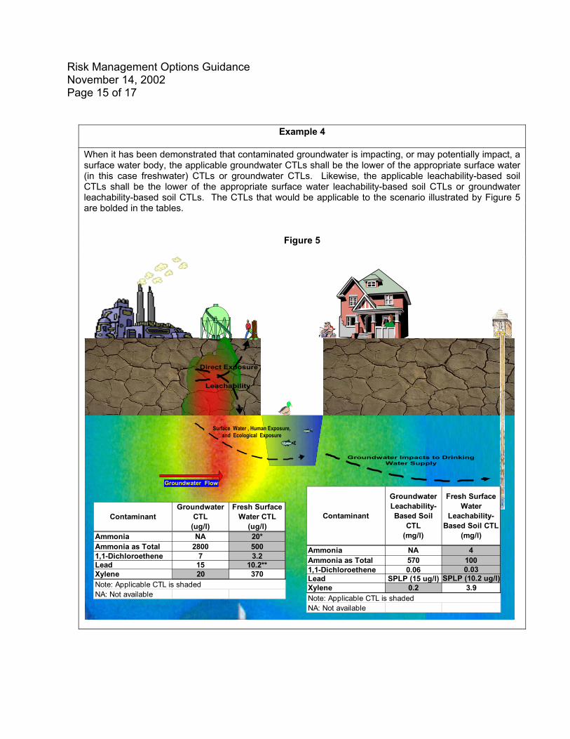
Risk Management Options Guidance November 14, 2002 Page 15 of 17
Example 4
When it has been demonstrated that contaminated groundwater is impacting, or may potentially impact, a surface water body, the applicable groundwater CTLs shall be the lower of the appropriate surface water (in this case freshwater) CTLs or groundwater CTLs. Likewise, the applicable leachability-based soil CTLs shall be the lower of the appropriate surface water leachability-based soil CTLs or groundwater leachability-based soil CTLs. The CTLs that would be applicable to the scenario illustrated by Figure 5 are bolded in the tables.
Figure 5
Leachability
Surface Water , Human Exposure,and Ecological Exposure
Direct Exposure/
Groundwater Flow
ContaminantGroundwater
CTL (ug/l)
Fresh Surface Water CTL
(ug/l)Ammonia NA 20*Ammonia as Total 2800 5001,1-Dichloroethene 7 3.2Lead 15 10.2**Xylene 20 370
NA: Not availableNote: Applicable CTL is shaded
Contaminant
Groundwater Leachability-Based Soil
CTL (mg/l)
Fresh Surface Water
Leachability-Based Soil CTL
(mg/l)
Ammonia NA 4Ammonia as Total 570 1001,1-Dichloroethene 0.06 0.03Lead SPLP (15 ug/l) SPLP (10.2 ug/l)Xylene 0.2 3.9
NA: Not availableNote: Applicable CTL is shaded
Groundwater Impacts to DrinkingWater Supply
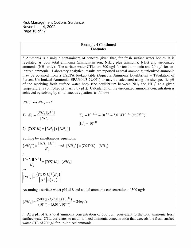
Risk Management Options Guidance November 14, 2002 Page 16 of 17
Example 4 Continued Footnotes
* Ammonia is a unique contaminant of concern given that, for fresh surface water bodies, it is regulated as both total ammonia (ammonium ion, NH4
+, plus ammonia, NH3) and un-ionized ammonia (NH3 only). The surface water CTLs are 500 ug/l for total ammonia and 20 ug/l for un-ionized ammonia. Laboratory analytical results are reported as total ammonia; unionized ammonia may be obtained from a USEPA lookup table (Aqueous Ammonia Equilibrium – Tabulation of Percent Un-Ionized Ammonia, EPA/600/3-79/091) or may be calculated using the site-specific pH of the receiving fresh surface water body (the equilibrium between NH3 and NH4
+ at a given temperature is controlled primarily by pH). Calculation of the un-ionized ammonia concentration is achieved by solving by simultaneous equations as follows:
++ +↔ HNHNH 34
1) ][
]][[
4
3+
+
=NH
HNHKa (at 25103.9 1001.51010 −−− === XK apK
aoC)
[H+] = 10-pH 2) [ ][][] 43
++= NHNHTOTAL Solving by simultaneous equations:
aKHNH
NH]][[
][ 34
++ = and [ ][][] 34 NHTOTALNH −=+
∴
][][]][[
33 NHTOTALKHNH
a
−=+
or
[ ] ( ) ([ ] ( )
)a
a
KHKTOTAL
NH+
= +
*3
Assuming a surface water pH of 8 and a total ammonia concentration of 500 ug/l:
lugXXlugNH /24
)1001.5()10()1001.5)(/500(][ 108
10
3 =+
= −−
−
∴ At a pH of 8, a total ammonia concentration of 500 ug/l, equivalent to the total ammonia fresh surface water CTL, correlates to an un-ionized ammonia concentration that exceeds the fresh surface water CTL of 20 ug/l for un-ionized ammonia.
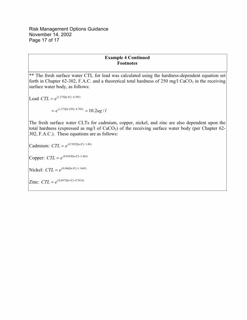
Risk Management Options Guidance November 14, 2002 Page 17 of 17
Example 4 Continued Footnotes
** The fresh surface water CTL for lead was calculated using the hardness-dependent equation set forth in Chapter 62-302, F.A.C. and a theoretical total hardness of 250 mg/l CaCO3 in the receiving surface water body, as follows: Lead CTL )705.4][ln273.1( −= He luge /2.10)705.4]250[ln273.1( == −
The fresh surface water CLTs for cadmium, copper, nickel, and zinc are also dependent upon the total hardness (expressed as mg/l of CaCO3) of the receiving surface water body (per Chapter 62-302, F.A.C.). These equations are as follows: Cadmium: )49.3][ln7852.0( −= HeCTL Copper: )465.1][ln8545.0( −= HeCTL Nickel: CTL )1645.1][ln846.0( −= He Zinc: CTL )7614.0][ln8473.0( −= He
RBCA GUIDANCE No. 4February 28, 2003
POLLUTION REMEDIATION SECTION ACTIVE REMEDIATION GUIDANCE FOR CONTAMINATED SITES REGULATED BY
SECTION 24-11.1(2), CODE OF MIAMI-DADE COUNTY This document provides general guidelines for preparing and implementing Remedial Action Plans (RAPs). Applicability This guidance is generally applicable to all RAPs; however, additional specific guidelines (RBCA Guidance Nos. 4A – 4L) are also available for the following: soil vapor extraction systems, groundwater recovery systems, granular activated carbon systems, bioremediation, in-situ air sparging, multi-phase extraction systems, air stripping towers, bioventing, biosparging, groundwater disposal systems, RAP status reports and post-RAP monitoring only plans (MOPs). Background The objective of active remediation is to meet the applicable no further action (NFA) or NFA with conditions criteria in Section 24-11.1(2)(J), Code of Miami-Dade County (“the Code”), or to qualify for natural attenuation with monitoring in accordance with Section 24-11.1(2)(K)(1)(a) of the Code (see also Natural Attenuation Guidance Document No. 5). The RAP shall provide a design (using a single remedial technology or a combination of remedial technologies) that addresses (simultaneously or in phases) all contaminants of concern (COCs) in all contaminated media (i.e., soil, sediment, groundwater, or surface water). Prior to submitting a RAP, a pilot test may be required to evaluate the feasibility of the technology and to effectively design the final system. RAP Requirements The RAP shall include the following general information, in addition to the requirements provided by the specific remediation guidance documents, as applicable: 1. The following information from the approved Site Assessment Report (SAR):
a. A summary of the conclusions and recommendations; b. A summary of the site lithology and hydrogeology; c. Summary table(s) of analytical results for all impacted media (including free
product, if present) obtained during site assessment; d. A summary of any additional data obtained since the approval of the SAR; and

Active Remediation Guidance February 28, 2003 Page 2 of 5
e. Site diagram(s) (indicating the North direction, drawn to scale, and including a graphical representation of the scale) depicting the horizontal and vertical delineation of the plumes for each impacted media, including monitoring wells (MWs) and soil boring locations and any other pertinent features (e.g., underground utilities, nearby surface water bodies or other potential receptors, backfill areas, drainage systems, surface seal, aquifer heterogeneities, etc.).
2. If groundwater contamination is present, analytical results for groundwater samples
collected from a number and location of MWs which is adequate to determine the distribution of COCs, to verify the horizontal and vertical extent of the plume, and to provide design data for the RAP or pilot test. Be advised that the groundwater data utilized to design the remedial system and, as applicable, the pilot test shall be no older than 270 days. If the results from the confirmatory round of sampling contradict earlier results (e.g., potential new source, free product, significant increase in COC concentrations, etc.), then applicable site assessment tasks (see Site Assessment Guidance No. 2) shall be performed.
3. The rationale for the active remediation method selected, including, as appropriate,
the results from any pilot studies or bench tests. Furthermore, a cost evaluation, considering all costs (e.g., pilot testing; system design, installation, operation and maintenance; monitoring, etc.) associated with all applicable alternatives (e.g., natural attenuation with monitoring, pump and treat, etc.), should be performed to support the selected remedial technology.
4. The remedial goals (i.e., applicable cleanup target levels, CTLs, alternative CTLs,
or natural attenuation criteria) and the estimated time of cleanup (including technical support). For groundwater, annual reductions of COC concentrations in all designated MWs shall be estimated in the proposal to verify annual progress.
5. An evaluation of the production of breakdown contaminants or by-products
resulting from bioremediation, oxidation, or other (including natural) processes, as applicable.
6. A summary of the design and construction details for all equipment. 7. The operational details of the remedial system(s) to be used during active
remediation, including the following, as appropriate:
a. The expected concentrations of COCs in the influent for each remedial component (e.g., soil vapor extraction system, air stripping tower, etc.), including supporting calculations (e.g., weighted average procedure, results of dynamic samples from the pilot test, etc.) for the estimated concentrations;
b. Design calculations for all remedial systems;
Active Remediation Guidance February 28, 2003 Page 3 of 5
c. The expected concentrations of COCs in the effluent for each remedial
component, including supporting calculations for the estimated concentrations; d. The disposition of any effluent (see Groundwater Disposal Systems Guidance
No. 4D); e. The method of air emissions treatment and the expected quantities in pounds
per day of any COCs discharged into air as a result of all on-site active remediation systems. A separate air permit will not be required if the total hazardous air pollutants (HAPs) from all on-site remediation equipment system(s) do not exceed 13.7 pounds per day. For on-site remediation equipment system(s) located at a facility that is a Title V source pursuant to Chapter 62-213, F.A.C., a separate permit under that chapter may be required;
f. The rates and concentrations of any in situ enhancement technologies
implemented. Be advised that the placement of any compound (other than air) into the soils or groundwater may require prior FDEP and DERM approval. To obtain DERM approval, a Product Submittal Application shall be submitted to the Pollution Remediation Section (PRS) of DERM. Questions regarding the need to submit a product application should be addressed to the PRS at (305) 372-6700; and
g. The schedule for maintenance of the remediation system.
8. A description of the monitoring plan that will be implemented during active
remediation. A thorough monitoring strategy is necessary to provide effective dynamic management of the system. When developing the monitoring strategy, the monitoring requirements provided in the specific remediation guidance documents shall be considered, as applicable, in addition to the general requirements provided by the RAP Status Reports Guidance (RBCA Guidance No. 4K).
9. The details of any proposed treatment or disposition of contaminated soil or
sediment. If contaminated soil exists at the site and active remediation does not include treatment or removal of such soil, the RAP shall include a proposal to implement an institutional and, if applicable, engineering control, pursuant to Section 24-11.1(2)(J)(2) of the Code.
10. A discussion of when the active remediation will be discontinued. The
discontinuation of active remediation may be appropriate at any time, depending on the site-specific characteristics and conditions.
Active Remediation Guidance February 28, 2003 Page 4 of 5
11. Copies of all applicable permits or authorizations required for site rehabilitation activities (e.g., underground injection control, UIC, permit, National Pollutant Discharge Elimination System permit, variance from Rule 62-522.300(3), F.A.C., etc.). Be advised that other federal or State requirements may apply to these activities.
RAP Implementation Requirements The following are required prior to or during implementation of the approved RAP: 1. Prior to constructing the remedial system, the responsible party shall submit
construction plans for DERM approval and obtain the appropriate permits and approvals, including those from other county departments or municipalities (e.g., building and zoning permits, electrical permits, etc.).
2. Within 120 days of the approval of the RAP, operation of the active remediation
system shall be initiated and engineering drawings (As-Built Drawings) shall be submitted for DERM approval. The engineering drawings shall include all construction and equipment design specifications of the installed active remediation system(s) and any operational parameters different from those in the approved RAP. Be advised that any modification to the approved RAP (e.g., recovery well flow rate, etc.) may require a RPA modification approval from DERM. A summary of the system(s) startup activities shall be attached to the engineering drawings.
3. During active remediation, the monitoring plan approved in the RAP shall be
implemented and status reports of the remedial action shall be submitted for DERM review in accordance with the RAP Status Reports Guidance (RBCA Guidance No. 4K).
4. If effluent concentrations or air emissions exceed those in the approved RAP,
plume migration occurs, major operational problems arise, or a new discharge is detected at startup or during operation of the remedial system, corrective actions shall be taken and DERM shall be notified by the responsible party within seven (7) days. If the condition represents a potential threat to human health, public safety or the environment, the responsible party shall immediately implement the necessary actions to eliminate the threat and shall notify DERM within twenty four (24) hours. Details of all such incidents shall be included in the status report (see RAP Status Reports Guidance No. 4K).
Completion or Discontinuation of the Approved RAP 1. Completion: Upon demonstrating that the remedial goals (i.e., the applicable CTLs
or alternative CTLs have been achieved or the site qualifies for natural attenuation
Active Remediation Guidance February 28, 2003 Page 5 of 5
a.
b.
with monitoring) specified in the approved RAP have been achieved, the responsible party shall submit for DERM approval one or more of the following: a RAP modification (e.g., to deactivate soil remediation but continue with groundwater remediation), a post-RAP groundwater MOP (see Post-RAP MOP Guidance No. 4L) or a monitoring plan for natural attenuation (see Natural Attenuation Guidance No. 5). Demonstration that the remedial goals have been achieved shall be based upon the following:
For soil contamination, a sufficient number of confirmation samples shall be collected from representative locations determined in accordance with the soil plume delineation depicted in the approved SAR. For groundwater contamination, samples from a sufficient number of MWs, adequate to determine the distribution of COCs and to verify the horizontal and vertical extent of the plume, shall be collected. Samples shall be collected, no earlier than ten (10) days after deactivation of the system.
2. Discontinuation: If the remedial goals specified in the approved RAP have not been
achieved, the responsible party shall submit for DERM approval a proposal including one or more of the following: a modification to the approved RAP, alternative technologies or approaches, alternative closure options (e.g., NFA with conditions, alternative CTLs based upon site-specific soil properties or risk assessment, etc.), or a supplemental assessment to determine new or previously unidentified source areas. Be advised that active remediation shall continue while DERM is reviewing the proposal, unless written approval to shut-down the system has been granted by DERM. The proposal shall include, as appropriate, an analyses or demonstration of the following:
a. The technical feasibility of continuing with the existing remedial technology
(considering factors such as COC mass reduction rates over time, etc.); b. The technical feasibility of enhancements to the existing remediation system; c. The technical feasibility of other proven groundwater or soil treatment
techniques to further reduce the concentrations of COCs at the site; d. The costs and timeframes involved to further reduce the concentrations of
applicable COCs employing the alternative method(s) proposed; and
e. The feasibility of implementing institutional and, if applicable, engineering controls to achieve a no further action with conditions, in accordance with Section 24-11.1(2)(J)(2) of the Code and the Risk Management Options Guidance (RBCA Guidance No. 3).
RBCA GUIDANCE No. 4A
March 7, 2003POLLUTION REMEDIATION SECTION
SOIL VAPOR EXTRACTION SYSTEM GUIDANCE FOR CONTAMINATED SITES REGULATED BY SECTION 24-11.1(2), CODE OF MIAMI-DADE COUNTY
This document provides general guidelines for soil vapor extraction (SVE) systems. Applicability SVE is a cleanup technology that is applicable to volatile and semi-volatile contaminants of concern (COCs) in the vadose zone (i.e., unsaturated soil). SVE may be utilized as a sole remedial technique or incorporated with other technologies (e.g., prior to bioventing or natural attenuation, etc.) to provide a cost effective remedial approach. Pilot Testing A pilot test is required for SVES designs which do not include an impermeable surface seal and may be required in other situations, for example, at sites with expansive plumes (i.e., greater than one half acre) or complex lithologies, to evaluate the feasibility of the technology and effectively design the treatment system. Proper technical justification shall be provided at the time of the Remedial Action Plan (RAP) submittal if a pilot test is not performed. Prior to implementation of the pilot test, a pilot test plan shall be submitted for DERM approval. The pilot test plan shall include, at a minimum, the following information: 1. A site diagram (indicating the North direction, drawn to scale, and including a
graphical representation of the scale) depicting the following:
a. The horizontal and vertical delineation of the plumes for each impacted medium and any other pertinent features (e.g., underground utilities, nearby surface water bodies, backfill areas, drainage systems, surface seal, aquifer heterogeneities, etc.); and
b. The location of the test well network, consisting of dedicated vacuum extraction
wells (VEWs) and observation wells, and the location of the impervious surface seal.
2. Dedicated VEWs are required to effectively implement the pilot test. Consider the
following during the VEW design:
a. VEW(s) shall be located within the most contaminated area (i.e., highest concentration of COCs) of the plume, or as close is as physically possible;
SVES Guidance March 7, 2003 Page 2 of 6
b. VEW(s) shall be screened in accordance with the concentration profile of the COCs, considering the depth to groundwater and stratification of soil, as applicable; and
c. The pilot test VEW(s) should be utilized, if feasible, in the final design.
3. Observation wells are required to accurately monitor the observed vacuum readings
throughout the test. Dedicated observation wells are recommended. Consider the following during the observation well design:
a. The number of observation wells shall be sufficient to properly evaluate the
operational conditions; b. The screen interval of the observation wells shall be equivalent to the screen
interval of the VEWs;
c. Observation wells shall be located in a radial pattern, to evaluate the influence of the SVES in all directions, and shall be located at appropriate distances from the VEW(s) (e.g., 5 ft., 10 ft., 20 ft., 30 ft., etc.); and
d. The observation wells shall be appropriately located to evaluate the following: 1)
anisotropic conditions (e.g., backfill, tank farms, drainage structures, etc.), and 2) areas of potential preferential pathways resulting from varying surface seals (e.g., grassy areas, dispenser islands, etc.).
4. The impervious surface seal (e.g., concrete), if utilized, should be representative of
the final design. Be advised that if a surface seal is not utilized in the final design, the pilot test results must demonstrate that the seal is unnecessary.
5. Construction details of all the VEWs and observations wells. 6. Off-gas discharge and, if necessary, treatment design. A minimum off-gas
discharge stack of fifteen (15) feet is required. The discharge stack shall not be located in close proximity to any potential receptors (e.g., workers, air intake systems, etc.).
Off-gas treatment shall be provided if any of the following conditions exist: a. The system is operated for more than eight (8) hours (therefore, limiting the
length of pilot test to no more than eight (8) hours is recommended); b. The site of the pilot test is in close proximity to inhabited areas; or

SVES Guidance March 7, 2003 Page 3 of 6
a.
b.
c.
d.
c. Operation of the system is likely to result in adverse health effects or nuisance
conditions. 7. A monitoring proposal, including parameters and frequency. A step increase
application, performed using a minimum of four (4) step increases in the applied vacuum/flow, is required to fully evaluate the flow processes within the vadose zone. Equipment shall be properly designed to adequately influence the vadose zone at the highest steps. The following should be measured at each step interval:
Applied vacuum at the vacuum extraction wellhead;
Flow rate, including the flow stream temperature and pressure at the location of the flow rate measurement to accurately convert the rate to standard temperature and pressure;
Observed vacuum at each observation well; and
Volume of groundwater recovered.
8. A minimum of two (2) off-gas samples for COCs and total hazardous air pollutants
(HAPs) shall be obtained during the step that is considered to be most representative of the final design.
SVES Design The results of the pilot test, as appropriate, shall be summarized in the RAP and utilized to support the final design (see also “Soil Vapor Extraction Technology, Reference Handbook”, 1991, EPA/540/2-91/003, USEPA Office of Research and Development for more information regarding SVES design). In addition to the pilot test requirements, a full-scale SVES proposal requires the following: 1. The general information specified in Active Remediation Guidance No. 4. 2. All data from the SVES pilot test (e.g., vacuum readings, flow rates, VEW and
observation well construction details, etc.) and any other relevant observations documented during the pilot test (e.g., rain, excessive groundwater recovery, fluctuations in vacuum readings, etc.). If a pilot test was not conducted, provide the proper justification.
3. A demonstration that the SVES design features (e.g., number of VEWs, screen
length, location, size, flow rate, applied vacuum, etc.) are justified by the results of
SVES Guidance March 7, 2003 Page 4 of 6
the pilot test. If the pilot test was not conducted or is not representative of the proposed system (e.g., vertical to horizontal VEWs, etc.), detailed calculations are required to support the final design. Be advised that if a surface seal is not used in the final design, the design must be fully supported by a representative pilot test.
4. All proposed SVES construction details and technical specifications (e.g., VEW
screen depth and slot size, piping layout, gauge and sample port locations, air/water separator, filters, etc.).
5. Off-gas treatment design. The design shall consider the results of the dynamic
samples obtained during the pilot study, the design flow rate and, as applicable, potential generation of products of incomplete destruction (e.g., chlorine gas, dioxins, etc.). All supporting technical calculations and manufacturer’s specifications shall be included. Off-gas treatment shall be implemented in accordance with all applicable federal, state and local codes and regulations.
Note that if the intent of the SVE system is solely to supply oxygen for purposes of bioremediation (i.e., See Bioventing Guidance No. 4I), off-gas treatment may not be required. The site-specific oxygen mass loading requirements for bioremediation shall be justified within the technical design. Proposals to bypass off-gas treatment must be supported by off-gas sample analyses obtained during the pilot test.
6. An evaluation of the noise levels based upon the proposed equipment and the
surroundings. A noise abatement device may be required to avoid nuisance conditions.
7. The calculations and methodology used to determine the radius of influence for the
final design, using a recommended terminus vacuum of 0.5 inches of water gauge (wg) and considering, as applicable, the effects of superimposition on multiple VEW systems. This may include empirical calculations (see Johnson, et. al., 1992) to determine the air conductivity or a graphical interpretation of the step test results (i.e., vacuum vs. distance, vacuum vs. time).
8. Calculations of head loss (e.g., from friction, etc.) using the final design flow rate and
manufacturer technical specifications for the selected blower. Note that flow rates obtained during the pilot testing may require a conversion to standard pressure and temperature for blower selection. For sites with multiple extraction points and piping manifolds, a stepped increase in the piping diameter may be required to reduce friction losses. Manufacturer specifications shall be provided for the estimated friction losses through all equipment (e.g., air/water separators, filters, carbon vessels, pipe fittings, etc.). In addition, proper technical justification shall be presented if an explosion proof blower is not proposed.

SVES Guidance March 7, 2003 Page 5 of 6
d.
9. Site diagram(s) (indicating the North direction, drawn to scale and including a
graphical representation of the scale) depicting the location of the impervious surface seal, as applicable, the proposed SVES layout, and the predicted vacuum contours superimposed over the delineated soil plume.
Monitoring Requirements The SVES monitoring schedule set forth in the RAP shall include, at a minimum, the following: 1. The general monitoring requirements provided by the RAP Status Reports Guidance
No. 4K. 2. The following parameters, recorded weekly during the first month, monthly for next
two months, and quarterly thereafter:
a. Applied vacuum measurements obtained at the vacuum extraction wellhead; b. Observed vacuum measurements obtained from approved monitoring locations; c. Air/Vapor flow rates; and
Volume of recovered fluids. Off-Gas Treatment Removal A proposal to discontinue off-gas treatment may be submitted after the first thirty (30) days of system operation per extraction area if the mass of total HAPs in the emissions from all on-site remediation equipment does not exceed 13.7 pounds per day. Writenn DERM approval is required prior to removing the off-gas treatment and a minimum off-gas discharge stack of fifteen (15) feet is required after the off-gas treatment removal proposal is approved. The following items shall be submitted in the SVES off-gas treatment removal proposal: 1. All dynamic influent sample results for all approved parameters for the duration of
the system operations. 2. Flow rates, vacuum readings per VEW, and vacuum readings from
observation/monitoring wells for the duration of the system operations.
SVES Guidance March 7, 2003 Page 6 of 6
3. A contour map (indicating North direction, drawn to scale and including a graphical representation of the scale) depicting the radial influence of the active system to verify the treatment of contaminated soil throughout the site. Include the observed vacuum at each observation well that was used to generate the contours.
4. A diagram (indicating the North direction, drawn to scale, and including a graphical
representation of the scale) depicting any on-site or off-site receptors (e.g., workers, air intake systems, etc.) in the vicinity of the off-gas discharge stack.
5. System maintenance and down time summaries per area of treatment, including a
summation of the total number of days the system has been operating. 6. Mass removal rates in pounds per day for all remedial activities on site (e.g., SVES,
stripping towers, etc.). Include the flow rates and concentrations per system that were used to estimate the mass removal rates.
7. An evaluation of the system performance and mass contaminant removal, providing
technical justification for the off-gas treatment termination (i.e., mass removal efficiency vs. time of operation). Note that off-gas treatment removal may not be terminated if the mass removal rate has been determined to be increasing with time.
RBCA GUIDANCE No. 4BFebruary 28, 2003
POLLUTION REMEDIATION SECTION GROUNDWATER RECOVERY SYSTEMS GUIDANCE FOR CONTAMINATED SITES
REGULATED BY SECTION 24-11.1(2), CODE OF MIAMI-DADE COUNTY This document provides general guidelines for designing groundwater recovery systems. Applicability This guidance is applicable to pump and treat (or disposal) systems for the purpose of remediating contaminated groundwater in accordance with Section 24-11.1(2)(K)(3) of the Code of Miami-Dade County. Groundwater recovery systems are used to recover (“pump”) contaminated groundwater for ex-situ treatment (e.g., see Granular Activated Carbon Guidance No. 4C, Air Stripping Guidance 4H, etc.) and subsequent discharge (see Groundwater Disposal Systems Guidance No. 4D) or for direct disposal. Pumping Test A groundwater pumping test is required to evaluate the feasibility of a groundwater recovery system and to determine the aquifer characteristics in the area of contamination, unless the aquifer characteristics from a nearby site with a similar recovery well design and lithology are available. The following are general guidelines for implementing the pumping test: 1. The following, at a minimum, shall be considered during the recovery well (RW)
design: a. A capacity test shall be conducted prior to commencing the pumping test to
determine the maximum yield of the RW. b. The RW shall be located, in general, within the most contaminated area (i.e.,
highest concentration of COCs) of the plume, or as close as is physically possible, considering the following: i. Groundwater plume distribution (horizontal and vertical) and COC
concentration history; ii. Estimated time for cleanup and travel time from the edge of the plume to the
RW; iii. Physical and chemical properties of the COCs (e.g., retardation factor, RF,
etc.); iv. Groundwater transmissivity and its variation with depth;
Groundwater Recovery Systems Guidance February 28, 2003 Page 2 of 4
v. Required radii of influence, accounting for the accuracy of the plume
delineation, and a recommended terminus groundwater drawdown of 0.1 feet;
vi. The need for multiple RWs and multiple screen depths to add flexibility to
the system, considering factors such as the size of the plume and vertical flow;
vii. Location of drainage systems; viii. Estimated influent concentration. The recovery wells should be located to
maximize the influent concentration (i.e., within the most contaminated area of the plume);
ix. Stagnation areas. Stagnation areas may be addressed by varying the flow
rate, recharge gallery location or on/off operation; and x. Treatment system recharge areas (e.g., infiltration gallery, recharge well,
etc.) and their impact on the recovery system and contaminant migration. c. The pump shall be capable of an extraction flow rate that is adequate to stress
the aquifer; d. A grout seal, sampling port, flow meter, check valve, and throttling valve are
required; and
e. The pumping test RW should be utilized, if feasible, in the final design.
2. The following, at a minimum, shall be considered during the observation well design:
a. The number of observation wells shall be sufficient to properly evaluate the operational conditions;
b. The screen interval of the observation well shall be similar to the screen interval
of the RWs and shall be based upon the expected horizontal and vertical area of influence of the RW (considering factors such as flow rate and groundwater transmissivity). Multiple screen intervals may be necessary to evaluate all impacted strata of the aquifer or the influence of multiple extraction points (i.e., RWs);
c. Observation wells shall be located in a radial pattern, to evaluate the influence of
the RW in all directions, and shall be located at appropriate distances from the RW (e.g., 5 ft., 15 ft., 30 ft, 50 ft., etc.); and
Groundwater Recovery Systems Guidance February 28, 2003 Page 3 of 4
d. The observation wells shall be appropriately located to evaluate 1) any
anisotropic conditions (e.g., backfill, tank farms, drainage structures, etc.), and 2) areas of potential preferential pathways (e.g., utilities, etc.).
3. Groundwater elevation measurements shall be taken from the RW, observation
wells and, if necessary, a background well (located beyond the predicted influence of the pump test to correct for outside influences such as tidal canals and levees).
These measurements should be taken under both static conditions (i.e., prior to the test) and dynamic conditions (i.e., throughout the test). When taking measurements under dynamic conditions, the following frequency is recommended (see “Analysis and Evaluation of Pumping Test Data” Second Edition, 1990, by G. P. Kruseman and N. A. de Ridder):
TIME FREQUENCY 0-2 min. 10 sec. 2-5 min. 30 sec. 5-15 min. 1 min. 15-50 min. 5 min. 50-100 min. 10 min. 100 min. - 5 hr. 30 min. 5-48 hr. 60 min. 4. Flow rate measurements shall be taken throughout the test. 5. Dynamic samples shall be collected, at a minimum, at the midpoint and end of the
pump test and shall be analyzed for all COCs to evaluate the effectiveness of the recovery system and to aid in the design of the treatment system. In addition, the sample collected at the end of the pumping test shall be analyzed for background data (e.g, iron, total organic carbon, total hardness, suspended solids, etc.).
Groundwater Recovery System Design The results of the pumping test shall be summarized in the Remedial Action Plan (RAP). In addition to the pumping test requirements, a groundwater recovery system proposal requires the following: 1. The general information specified in Active Remediation Guidance No. 4. 2. All data from the pumping test (e.g., flow rates, groundwater elevation
measurements, RW and observation well construction details, etc.) and any other relevant observations documented during the pumping test (e.g., rain, nearby surface water bodies, etc.).
Groundwater Recovery Systems Guidance February 28, 2003 Page 4 of 4
3. RW design (e.g., flow rate, number of RWs, screen length, location, etc.),
demonstrating that the system will capture the dissolved plume based on the pumping test data. Multiple recovery wells and screen depths may be appropriate (e.g, for COCs with high retardation factors, large plumes, etc.). If additional RWs are required, the RWs should be designed and located using the criteria provided in the Pumping Test section of this guidance.
4. All proposed groundwater recovery system construction details and technical
specifications (e.g., RW screen depth, diameter, location, slot size, etc.). 5. Calculations for the selection of the RW pump and manufacturer’s specifications,
including performance curves. 6. Calculations for groundwater transmissivity. Pumping test data interpretation should
consider, at a minimum, the following: unconfined aquifer, partially penetrating well(s), tidal influence, heterogeneous hydraulic conditions, RW construction, screen length, conductivity/transmissivity variation with depth, aquifer thickness, and lithology (see “Aquifer Testing: Design and Analysis of Pumping and Slug Tests” by K. J. Dawson and J. D. Istok, 1991 and “Analysis and Evaluation of Pumping Test Data” Second Edition, 1990, by G. P. Kruseman and N. A. de Ridder).
7. A site diagram (indicating the North direction, drawn to scale and including a
graphical representation of the scale) depicting contours with the estimated drawdowns (based upon the pumping test data), the superimposition effect for multiple recovery well systems, and the effect of the groundwater disposal system.
Monitoring Requirements The monitoring schedule set forth in the RAP shall include, at a minimum, the following: 1. The general monitoring requirements provided by the RAP Status Reports Guidance
No. 4K. 2. The following, recorded monthly for the first year and quarterly thereafter:
a. RW downtime (i.e., hours of operation); b. Flow rates per recovery well; and c. Volume of groundwater treated.
3. Groundwater elevations from designated monitoring wells, RWs, and recharge
gallery piezometers, recorded quarterly.
RBCA GUIDANCE No. 4COctober 16, 2002
POLLUTION REMEDIATION SECTION
GRANULAR ACTIVATED CARBON SYSTEMS GUIDANCE FOR CONTAMINATED SITES REGULATED BY SECTION 24-11.1(2), CODE OF MIAMI-DADE COUNTY
This document provides general guidelines for granular activated carbon (GAC) systems. Applicability GAC systems may be utilized, for dissolved and gaseous contaminants of concern (COCs), as an exclusive primary remedial technology, in combination with other technologies (e.g., off-gas treatment following soil vapor extraction, air stripping, etc.), or as a polishing unit after a primary system to ensure that cleanup standards are met. Depending on the specific use, the guidelines provided by Groundwater Recovery Systems Guidance No. 4B and Groundwater Disposal Systems Guidance No. 4D may also be applicable. Polishing Units GAC may be useful or, in some cases (e.g., sites with significant levels of non-volatile COCs such as TRPH, PAHs, etc.), may be required for effluents that require polishing prior to discharge (e.g., discharge to surface waters, discharge via an injection well, etc., see Groundwater Disposal Systems Guidance No. 4D). The following information regarding the polishing unit design shall be submitted in the Remedial Action Plan (RAP): 1. The general information specified in Active Remediation Guidance No. 4. 2. The selection criteria for the carbon-polishing unit, as follows:
a. Empty bed contact time (EBCT). In general, the EBCT should be no less than 7 – 12 minutes;
b. Liquid loading rate (2 – 10 gpm/ft2); c. Length of column; d. Applicable isotherms;
e. Carbon usage rate, accounting for all groundwater background constituents (e.g.,
suspended solids, iron, etc.) and considering the effect (adsorption competition) of seasonal variation of Total Organic Carbon (TOC);
Granular Activated Carbon Systems Guidance October 16, 2002 Page 2 of 4
f. Pressure drop; and g. Manufacturer specifications.
2. A detailed description of the GAC system design, considering, at a minimum, the following: a. A multistage carbon system, consisting of a minimum of two (2) canisters in
series with a sampling port located prior to the final canister, is required to enable monitoring of the treated water prior to complete system breakthrough and to maximize the absorption capacity;
b. A filtration system is required prior to the activated carbon. Iron and calcium
precipitation shall be evaluated for polishing units following an aeration system and, if necessary, alternate treatment methodologies should be considered; and
c. A pressure gauge and pressure release valve is required. A safety system is
required to shutdown the remedial system if the carbon unit pressure approaches the manufacturer specifications for the carbon vessel.
3. An evaluation of the need for a backwash system and supporting calculations for the
final alternative, as appropriate. 4. The schedule for sampling between carbon adsorption units, considering the
absorption capacity and the estimated time for breakthrough. Primary System The following information regarding the primary system design shall be submitted in the RAP: 1. All the information described in the Polishing Units section of the guidance, except
that the EBCT should be no less than fifteen (15) minutes. 2. Site-specific isotherm data for the COCs. The isotherms may be generated from a
pilot study or an appropriate laboratory test. Laboratory bench tests shall provide sufficient contact time so as to allow the test cell to approach equilibrium conditions. The isotherm should be generated with a range of concentration so as to include the expected initial concentration.
Granular Activated Carbon Systems Guidance October 16, 2002 Page 3 of 4 Off-gas Treatment The following information regarding the off-gas treatment design shall be submitted in the RAP:
1. The general information specified in Active Remediation Guidance No. 4. 2. Carbon usage rates, considering the following:
a. total hazardous air pollutants (HAPs) in the waste stream. Total HAPs should be obtained during the pilot test. The design shall account for the treatment of at least 99% of the emissions during the initial thirty (30) days of operation (see Soil Vapor Extraction System Guidance No. 4A);
b. The temperature increase, if the carbon units are installed following the vacuum blower. The blower manufacturer must provide waste stream temperature estimates; and
c. The reduced pressure (vacuum) and humidity, if the carbon units are installed
prior to the vacuum blower. 3. A detailed description of the design, considering, at a minimum, the following:
a. A multistage carbon system, consisting of a minimum of two (2) canisters in series with a sampling port located prior to the final canister, is required to enable monitoring of the treated waste stream prior to complete system breakthrough; and
b. A pressure gauge and pressure release valve is required. A safety system is
required to shut down the remedial system if the carbon unit pressure approaches the manufacturer specifications for the carbon vessel.
4. The schedule for sampling between carbon adsorption units, considering the
absorption capacity and the estimated time for breakthrough. Monitoring Requirements The monitoring schedule set forth in the RAP shall include, at a minimum, the following: 1. The general monitoring requirements required by the RAP Status Reports Guidance
No. 4K.

Granular Activated Carbon Systems Guidance October 16, 2002 Page 4 of 4
2. Pressure in the carbon vessel, as applicable, monitored monthly for the first quarter, and quarterly thereafter.

RBCA GUIDANCE No. 4DFebruary 28, 2003
POLLUTION REMEDIATION SECTION
GROUNDWATER DISPOSAL SYSTEMS GUIDANCE FOR CONTAMINATED SITES REGULATED BY SECTION 24-11.1(2), CODE OF MIAMI-DADE COUNTY
This document provides general guidelines for designing groundwater disposal systems. Applicability This guidance document is applicable to the discharge of remedial system effluents at contaminated sites that are remediated in accordance with Section 24-11.1(2)(K)(3) of the Code of Miami-Dade County. To protect and conserve the groundwater resources of Miami-Dade County, DERM strongly encourages on-site disposal of remedial system effluent via a recharge gallery, when feasible and cost-effective. Alternate disposal methods, however, may be required based on site-specific constraints. Recharge Gallery The following minimum information regarding the recharge gallery design shall be provided in the Remedial Action Plan (RAP): 1. The general information specified in Active Remediation Guidance No. 4. 2. The location of the proposed recharge gallery with respect to the groundwater and
soil contaminant plume, based upon the site assessment data. In general, the recharge gallery should not be located within the contaminant plume. However, if the recharge gallery is intended to aid in contaminant recovery, then the recharge gallery may be situated within the contaminant plume area provided that hydraulic control of the plume is maintained.
3. The results of a minimum of two (2) percolation tests per recharge area (e.g., area <
500 sq. ft.), considering the following:
a. The depth and location of the tests shall be representative of the proposed recharge gallery. Provide all data (e.g., lithology, flow rate, water elevation, etc.), observations (e.g., weather conditions, etc.), and the location of the percolation tests;
b. The appropriate test method shall be applied. In general, constant head tests
are recommended in highly permeable formations (typical of Miami-Dade County) and falling head tests are recommended in less permeable formations. Tests should be performed in accordance with the South Florida Water

Groundwater Disposal Systems Guidance February 28, 2003 Page 2 of 4
Management District, Environmental Resource Permit Information Manual, Volume IV; and
c. Additional percolation tests or alternative test methods (e.g., trench test, etc.)
may be required if significant inconsistencies are documented in test results from the same area or if warranted based upon the size of the recharge gallery. Historical background data and supporting data from neighboring sites under similar conditions (e.g., lithology, liquid loading rate, etc.) may be utilized.
4. Recharge gallery design calculations, construction details, and specifications,
considering the following: a. A minimum safety factor of 50% is recommended in the sizing of the gallery; b. A parallel looped distribution system is recommended for increased recharge
distribution (rather than a single perforated drainage line) and a minimum twelve-inch (12 in.) diameter perforated disposal pipe is recommended;
c. A minimum of one (1) piezometer per 100 feet of recharge gallery shall be
located within the recharge gallery. This piezometer shall be outfitted with a high water shutoff probe for the remedial system;
d. Geotextile filter fabric shall be installed on the sides and top of the recharge
gallery; and e. A minimum of one (1) cleanout port is required.
5. An analysis of mounding. The most conservative hydraulic conductivity value obtained from the field test shall be used in this analysis. Further efforts to verify the estimated mound value using operating recharge galleries in the vicinity that are equivalent (e.g., similar lithology, liquid loading, etc.) are recommended.
6. An evaluation and discussion of the recharge gallery's effect on the contaminant
movement and recovery system. 7. An evaluation of the need for a sedimentation chamber (or alternative method) to
prevent the recharge gallery from clogging. 8. A detailed evaluation for shallow water table (i.e., less than 2 - 3 feet below land
surface) and tidally influenced areas to ensure an effective design. Other methods of water disposal may have to be considered for these areas.
Groundwater Disposal Systems Guidance February 28, 2003 Page 3 of 4 Injection Well Prior to DERM approval of the injection well, a Florida Department of Environmental Protection, FDEP, underground injection control, UIC, permit shall be obtained and a copy of the UIC permit shall be submitted to DERM. The following minimum information regarding the injection well design shall be provided in the RAP: 1. West of the Isochlor Line
a. The screen interval depth of the injection well(s). The screen interval shall be representative of the groundwater recovery well(s);
b. The results of a constant head percolation test performed in the area of proposed
injection wells(s). The constant head test should be representative of the final design (e.g., screened interval, flow rate, etc.) and should be of a sufficient duration as to reach or approach asymptotic conditions;
c. An evaluation of the operational data of recharge wells in the vicinity of the site
(e.g., capacity, required maintenance, etc.); d. Injection well construction details and location, including support calculations,
based upon the results of the percolation/capacity test. Reductions in the recharge capacity as a result of clogging and fouling of the well screen shall be considered in the final design;
e. A description of the filtration system. A filtration system is required prior to the
injection well(s). In addition, injection wells shall be gravity fed and a high water shutoff probe for the remedial system shall be installed in the injection well; and
f. The general information specified in Active Remediation Guidance No. 4.
2. East of the Isochlor Line
a. The screen interval of the well. The screen shall extend within a depth of 10,000 ppm total dissolved solids (TDS) or 3,000 ppm chloride (usually encountered at a depth of 80 feet or more). A State of Florida licensed drill operator shall record TDS and chloride levels at the time of well installation;
b. A verification of the recharge capacity at the time of the installation by a State of
Florida licensed driller;

Groundwater Disposal Systems Guidance February 28, 2003 Page 4 of 4
c. Details of the monitoring well installed to the depth of the injection well, if required; and
d. Items c., d., e., and f. provided above for West of the Isochlor Line.
Surface Water Discharge The use of surface waters as a groundwater disposal method at contaminated sites requires a National Pollutant Discharge Elimination System (NPDES) permit from the FDEP. Any proposal to discharge to surface waters shall demonstrate that surface water disposal is the only feasible alternative. The RAP shall provide justification that all other disposal options have been fully investigated (e.g., percolation test results, recharge gallery design alternatives, etc.) to support the feasibility statement.

RBCA GUIDANCE No. 4E
March 10, 2003POLLUTION REMEDIATION SECTION
An appropriate environment must be maintained in order for the microorganisms to successfully degrade the COCs. Detailed site characterization and testing shall be performed to determine the site-specific feasibility of the technology, and to provide sufficient data (e.g., geochemical indications, subsurface sources, etc.) for the remedial design.
IN-SITU BIOREMEDIATION GUIDANCE FOR CONTAMINATED SITES REGULATED BY SECTION 24-11.1(2), CODE OF MIAMI-DADE COUNTY
This document provides general guidelines for in-situ bioremediation of contaminated soil or groundwater. Bioremediation is a complex process utilizing microorganisms (e.g., engineered, formulated, indigenous, etc.) and other enhancements (e.g., nutrients, electron acceptors/donors, oxygen, etc.), as necessary, to convert toxic contaminants into harmless end-products. Applicability Bioremediation is a cleanup technology that is suitable for a variety of organic contaminants of concern (COCs). Bioremediation may not be applicable when immediate control of the groundwater plume is required to prevent migration to a known receptor. Site Characterization
Bench Test/Pilot Test Appropriate testing (i.e., on-site pilot test, laboratory bench test or both, as applicable and feasible) is required to assess the feasibility of bioremediation and to obtain critical data (e.g., identification of any limiting parameters, such as oxygen, nutrients or electron acceptors/donors, in the degradation process, etc.) for the final design. The bench test/pilot test proposal shall be approved by DERM prior to implementation. The on-site pilot test provides information that is necessary to properly evaluate the technology under actual site conditions, while the laboratory bench test provides the data necessary to design the pilot test and to determine the feasibility of the technology. A pilot test alone is generally sufficient for cleanups at less complex sites, such as sites with limited contamination (approximately ¼ acre or less), readily degradable contaminants (e.g., hydrocarbons, etc.), or shallow contamination. For more complicated applications, however, a laboratory bench test may be required prior to the pilot test. The following are general guidelines for performing laboratory bench tests and pilot tests.
In-Situ Bioremediation Guidance March 10, 2003 Page 2 of 6
Laboratory Bench Test The following shall be provided in a laboratory bench test proposal: 1. A detailed description of the procedures and equipment to be used. 2. A discussion justifying the selection of an aerobic or anaerobic operation, as
appropriate. Under aerobic conditions, the application of oxygen and, as necessary, nutrients and microorganisms shall be fully evaluated. Under anaerobic conditions, the optimization of the appropriate electron acceptor shall be identified and justified.
3. The sampling parameters and frequency. 4. A description of the different amendment studies including, at a minimum, the
following: a. A control sample without any biodegradation enhancement; b. Samples with the addition of electron acceptors only; c. Samples with the addition of nutrients only; d. Samples with only microorganisms or a specific product/formulation, if
determined necessary; and e. Samples with the addition of a combination of amendments or a specific
product/formulation (e.g., microorganisms, electron acceptors, nutrients, etc.), if determined necessary.
5. A description of the laboratory conditions and a comparison to the actual field
conditions (Note: every effort must be made to ensure that the laboratory conditions are as representative of the field conditions as possible.).
6. A description (e.g., COC concentrations, locations, etc.) of the groundwater samples
to be used for the test. The samples shall be representative of the dissolved COC distribution at the site. All samples shall be monitored under the same conditions for all applicable parameters.
7. A list of the parameters to be monitored during the bench test, including, at a
minimum, the following: electron acceptors; temperature; pH; COC concentrations;

In-Situ Bioremediation Guidance March 10, 2003 Page 3 of 6
nutrient levels; oxidation-reduction potential; and, as appropriate, microbial population count (optional).
Pilot Test The following shall be provided in a Pilot Test Proposal:
1. A site diagram(s) (indicating the North direction, drawn to scale, and including a
graphical representation of the scale) depicting the horizontal and vertical delineation of the plumes for each impacted medium and any other pertinent features (e.g., utilities, surface seals, buildings and potential receptors, etc.).
2. Construction details and locations of all injection points and observation wells. 3. A demonstration that horizontal and vertical plume control will be maintained
during the pilot test (Note: if a pump and treat system is needed to maintain plume control, the cost effectiveness of bioremediation as an enhancement should be considered).
4. A description of all design parameters, clearly defined, including, at a minimum, the
following:
a. A discussion of the processes involved in the biodegradation of the COCs, including potential by-products and daughter products, to determine the environment (i.e., aerobic or anaerobic) that is optimal for degradation and to determine the optimum operational levels. Under aerobic conditions, the application of oxygen and, as necessary, nutrients and microorganisms, shall be fully evaluated. Under anaerobic conditions, the appropriated electron acceptor shall be identified and justified;
b. Verification of transport mechanisms considering all introduced parameters
(e.g., electron acceptors, nutrients, microorganisms, etc.) and other pertinent factors such as aquifer characteristics, optimum ranges and radial influence. The method(s) to verify these mechanisms in the pilot study shall be included;
c. A discussion of the optimization of the soil moisture content in the vadose zone,
evaluated in locations where bioremediation of the soils is considered; and d. If combinations of products are proposed, an evaluation of 1) potential
interactions among the products, and 2) the effect the proposed quantities will
In-Situ Bioremediation Guidance March 10, 2003 Page 4 of 6
have on the environment where the biochemical reactions will occur (e.g., pH changes, hydrocarbon mass, oxygen depletion, need for microorganisms, etc.).
5. Complete technical justification for the loading requirements of any enhancements
to be introduced (e.g., electron acceptors, nutrients, cometoblic compounds, micro organisms, etc.) This technical justification shall include, at a minimum, the following:
a. the stoichiometric requirements of each enhancement needed to degrade the
contaminants in the groundwater (including unregulated compounds and daughter products);
b. any additional demands within the aquifer. This may include sampling source
area and background monitoring wells for biological oxygen demand (BOD), chemical oxygen demand (COD), or other relevant parameters; and
c. any mass transfer from the introduced medium to the applicable medium (e.g.,
the mass transfer of gaseous enhancements to the aquifer). 6. Identification of the control area (i.e., a location where no enhancements are
administered) to be monitored for all applicable parameters. The control area, if feasible, shall be representative of the pilot test area (e.g., similar COCs, concentrations of COCs, lithology, surface seal, etc.).
7. A discussion detailing how representative the proposed pilot study is of the full-
scale design. 8. A description of the techniques (e.g. sampling parameters, frequency, procedures,
etc) to evaluate the effectiveness and progress (e.g., radius of influence, reduction in COC concentrations, minimum acceptable concentrations of the introduced or monitored parameters, etc.) of the bioremediation system during the pilot study.
9. A completed UIC Notification Form for any injection-type aquifer remediation plan
(e.g. magnesium peroxide, re-injection of treated water, etc.), and copies of any applicable variances (e.g., variance from Rule 62-522.300(2)(a)) and approvals (e.g., DERM product approvals) detailing all conditions.

In-Situ Bioremediation Guidance March 10, 2003 Page 5 of 6
Remedial Design: The results of the pilot test/bench test shall be summarized in the remedial action plan (RAP) and utilized to support the final design. In addition to the pilot test/bench test requirements, the RAP shall include, at a minimum, the following information: 1. The general information specified in Active Remediation Guidance No. 4. 2. Results of the pilot test/bench test, including, at a minimum, all laboratory results,
measurements, degradation kinetics of the different amendments (e.g., nutrients, electron acceptors, microorganisms, etc. at different mass loading), and a discussion of the applicability of the results of the test(s) to the site-specific conditions.
3. A discussion of the processes involved in the biodegradation of the COCs, including
potential by-products and daughter products, to determine the environment (i.e., aerobic or anaerobic) that is optimal for degradation and to determine the optimum operational levels.
Under aerobic conditions, the application of oxygen and, as necessary, nutrients and microorganisms, shall be fully evaluated. Dissolved oxygen (DO) concentrations shall be obtained (using an appropriate sampling technique to avoid aerating the sample) from monitoring wells located within the source area as well as from background monitoring wells. These results shall be evaluated to determine the site-specific suitability of utilizing the oxygen enhancement approach. Under anaerobic conditions, the appropriated electron acceptor shall be identified and justified.
4. Complete technical justification for the loading requirements of any enhancements to
be introduced (e.g., electron acceptors, nutrients, cometoblic compounds, micro organisms, etc.) This technical justification, supported by the results of the pilot/bench test, shall include the following:
a. The stoichiometric requirements of each enhancement needed to degrade the
contaminants in the groundwater (including unregulated compounds and daughter products);
b. Any additional demands within the aquifer. This may include sampling source
area and background monitoring wells for BOD, COD, or other relevant parameters; and
In-Situ Bioremediation Guidance March 10, 2003 Page 6 of 6
c. Any mass transfer from the introduced medium to the applicable medium (e.g., the mass transfer of gaseous enhancements to the aquifer).
5. The methodology selected to supply the enhancements to the aquifer. Be advised
that wells used for the distribution of enhancements to the aquifer are no longer representative of the surrounding aquifer conditions, and may not be used for monitoring the reduction of COCs in the aquifer.
6. Construction details and locations of all injection points. A site diagram(s) including
information such as utilities, surface seals, buildings, surface water bodies and possible receptors shall be provided.
7. A completed UIC Notification Form for any injection-type aquifer remediation plan
(e.g. magnesium peroxide, re-injection of treated water, etc.), and copies of any applicable variances (e.g., variance from Rule 62-522.300(2)(a)) and approvals (e.g., DERM product approvals) detailing all conditions.
8. A description of the techniques to evaluate the effectiveness and progress of the
bioremediation system during the full-scale system (e.g. sampling parameters, frequency, procedures, etc.).
9. A discussion detailing the transport of the enhancement into the aquifer. This
discussion shall include the optimum concentrations of the enhancement in the aquifer and justification for the estimated radial influence of the enhancement transport based on results of the pilot test.
Monitoring Requirements Monitoring for bioremediation systems shall include the general monitoring requirements provided by the RAP Status Reports Guidance No. 4K. In addition, monitoring shall include sampling of designated monitoring wells or soil sampling points representative of the impacted area for applicable bioremediation indicators (e.g., DO, rates of biological, chemical or nutrient enhancement additions, etc.), COCs, and any parameters required per applicable permits, variances or approvals. Monitoring shall be performed weekly for the first month, monthly for the next two months and quarterly for the remainder of the initial year. The monitoring frequency for subsequent years may be evaluated based on the results of the initial year.
RBCA GUIDANCE No. 4FMarch 11, 2003
POLLUTION REMEDIATION SECTION
IN-SITU AIR SPARGING GUIDANCE FOR CONTAMINATED SITES REGULATED
BY SECTION 24-11.1(2), CODE OF MIAMI-DADE COUNTY This document provides general guidelines for in-situ air sparging (IAS). Applicability IAS is a technology primarily used for the remediation of volatile and semi-volatile contaminants of concern (COCs) in the saturated zone (i.e, COCs dissolved in groundwater, within the capillary fringe or absorbed to soil below the water table). Be advised that IAS is not applicable to sites with free product. While the primary remediation mechanism for IAS is volatilization of the volatile compounds, enhancement of the bioremediation process may also be induced as a consequence of the injection of oxygen into the subsurface. In order to control the migration of the contaminated vapors from the saturated zone, the IAS is generally used in combination with a soil vapor extraction system, SVES (see Soil Vapor Extraction System Guidance No. 4A). Pilot Testing A pilot test may be required based on the suitability of the site for IAS and the complexity and extent of the COC plume. A pilot test may be elected to optimize the efficiency of the IAS system design. Proper technical justification shall be provided at the time of the Remedial Action Plan (RAP) submittal if a pilot test is not performed. Prior to implementation of the pilot test, a pilot test plan shall be submitted for DERM approval. The pilot test plan shall include, at a minimum, the following information: 1. A site diagram (indicating the North direction, drawn to scale, and including a
graphical representation of the scale) depicting the following:
a.
b.
a.
The horizontal and vertical delineation of the plumes for each impacted medium and any other pertinent features (e.g., underground utilities, nearby surface water bodies, backfill areas, drainage systems, surface seal, aquifer heterogeneities, etc.); and
The location of the test well network, consisting of dedicated vapor extraction well(s) (VEWs), air sparging well(s) (ASWs), and observation wells.
2. Guidelines for the design of the VEWs are provided in the Soil Vacuum Extraction
System Guidance No. 4A.
3. Dedicated ASWs are required to effectively implement the pilot test. Consider the following during the ASW design:
The screen interval of the ASW(s) shall be positioned below the delineated vertical extent of the dissolved COC plume;
In-Situ Air Sparging Guidance March 11, 2003 Page 2 of 5
b.
c.
d.
e.
a.
b.
c.
The ASWs shall be properly grouted immediately above the screened interval to eliminate shout-circuiting of the injected air to the atmosphere;
ASW(s) shall be located within the most contaminated area (i.e., area of highest COC concentration) of the plume;
Multiple ASWs and multiple injection points at various depths within a single ASW shall be considered, based upon the horizontal and vertical distribution of the COCs and geologic heterogeneities; and
The pilot test ASW(s) should be utilized, if feasible, in the final design.
4. Dedicated observation wells are required to accurately monitor the system
throughout the test. Consider the following during the observation well design:
A minimum of four (4) observation wells shall be utilized;
The screen interval of the observation wells shall be designed to properly monitor the vadose zone and the expected area of influence throughout the aquifer; and
Observation wells shall be located in a radial pattern at appropriate distances (e.g., 10, 20, 30 ft., etc.) from the ASWs to evaluate the influence of the IAS in all directions and to evaluate any anisotropic conditions (e.g., backfill, utilities, tank farms, drainage structures, etc.).
5. Construction details for all the VEW(s), ASW(s) and observation wells. 6. A demonstration that horizontal and vertical plume control will be maintained. 7. A monitoring proposal for the IAS system, including parameters and frequency as
follows:
a. At a minimum, the following data shall be obtained before, during and after the test:
i. Pressure/vacuum readings obtained at the wellheads of the VEW(s), ASW(s)
and observation wells; ii. Water elevation;
iii. Visual observations (e.g., bubbles, etc.);
iv. Dissolved oxygen; and
In-Situ Air Sparging Guidance March 11, 2003 Page 3 of 5
v. Field measured vapor concentrations in wells and system off-gas concentrations.
b. Groundwater samples shall be collected and analyzed for the COCs before and
after the test. c. A baseline off-gas sample for the COCs and total hazardous air pollutants shall
be obtained with only the SVES operating. d. At a minimum, one additional vapor sample for analyses shall be obtained at the
end of the combined operation of the IAS/SVES.
d. Periodic monitoring of vapor concentrations in areas of potential risk (e.g., buildings, etc.) shall be implemented during the performance of the test.
8. The safety mechanism or procedure (e.g., manual shut-down) to ensure that the IAS
will be under a sustained vacuum. The safety feature shall discontinue the IAS operations if positive readings are measured in any of the observation wells.
9. The proposed system flow rates. Note that the SVES shall operate at flow rates that
are at least 50% greater than the IAS flow rates. 10. Specifications of the equipment. Note that the air compressor shall have a sufficient
capacity to inject air at pressures that allow overcoming the sum of the hydrostatic pressure and the air-entry pressure of the formation. However, use of highly pressurized compressors shall be avoided. The pressure exerted by the weight of the soil column shall be estimated to establish a safe range of operation. Calculations supporting the proposed operating conditions shall be included.
11. Off-gas treatment design, as applicable. All supporting technical calculations and
manufacturer’s specifications shall be included. Off-gas treatment shall be implemented in accordance with all applicable federal, state and local codes and regulations.
Off-gas treatment shall be provided if any of the following conditions exist:
a. The system is operated for more than eight (8) hours (therefore, limiting the pilot test to no more than eight (8) hours is recommended);
b. The site of the pilot test is in close proximity to inhabited areas; or
c. Operation of the system is likely to result in adverse health effects or nuisance
conditions. Note that if the intent of the IAS system is solely to supply oxygen for purposes of
bioremediation (see Biosparging Guidance No. 4J), off-gas treatment may not be

In-Situ Air Sparging Guidance March 11, 2003 Page 4 of 5
required. The site-specific oxygen mass loading requirements for bioremediation shall be justified within the technical design. Proposals to bypass off-gas treatment shall be supported by off-gas sample analyses obtained during the pilot test.
IAS Design The results of the pilot test, as appropriate, shall be summarized in the RAP and utilized to support the final design. In addition to the pilot test requirements, a full-scale IAS proposal requires the following:
1. The general information specified in Active Remediation Guidance No. 4. 2. All data from the IAS pilot test (e.g., flow rates, ASW and observation well
construction details, etc.) and any other relevant observations documented during the pilot test (e.g., rain, etc.). If a pilot test was not conducted, provide the proper justification.
3. A demonstration that the IAS design features (e.g., number, construction and
location of ASWs, VEWs, observation wells, flow rates, applied pressure, etc.) are justified by the results of the pilot test. If the pilot test was not conducted or is not representative of the proposed system, detailed calculations are required to support the final design.
4. A site diagram(s) (indicating the North direction, drawn to scale and including a
graphical representation of the scale) depicting the proposed layout and all the components of the system (e.g., wells, piping, sampling ports, valves, etc.).
5. All proposed IAS construction details and technical specifications (e.g., well screen
depth and slot size, piping layout, gauge and sample port locations, etc.). Note that the vacuum blower and compressor shall be explosion-proof, unless otherwise technically justified. A pressure gauge and pressure release valve at the location of the discharge of compressor are required. In addition, a safety system shall be provided to discontinue the IAS operations in the event that the SVES fails.
6. An evaluation of the need for groundwater recovery wells in conjunction with IAS to
recover off-site groundwater contamination, to prevent off-site migration or to recover the vertical extent of the COC plume.
7. Off-gas treatment design. Off-gas treatment is required for, at least, the first thirty
(30) days of operation. The design shall consider the results of the dynamic samples obtained during the pilot study, the design flow rate and, as applicable, potential generation of products of incomplete destruction (e.g., chlorine gas, dioxins, etc.). All supporting technical calculations and manufacturer’s specifications shall be included. Off-gas treatment shall be implemented in accordance with all applicable federal, state and local codes and regulations.

In-Situ Air Sparging Guidance March 11, 2003 Page 5 of 5
8. An evaluation of the noise levels based upon the proposed equipment and the surroundings. A noise abatement device may be required to avoid nuisance conditions.
9. Calculation of the radius of influence for the final IAS design, using a graphical
interpretation of the step test results (e.g., dissolved oxygen vs. distance, pressure vs. distance) or an appropriate model. The radius of influence for the SVES shall be determined in accordance with the SVES Guidance No. 4A.
10. Calculations of head loss (e.g., from friction, etc.) and the manufacturer’s technical
specifications for the selected blower and compressor. Note that flow rates obtained during the pilot testing may require a conversion to standard pressure and temperature for blower and compressor selection. For sites with multiple extraction/injection points and piping manifolds, a stepped increase in the piping diameter may be required to reduce friction losses. Manufacturer specifications shall be provided for the estimated friction losses through all equipment (e.g., air/water separators, filters, carbon vessels, pipe fittings, etc.). In addition, proper technical justification shall be presented if an explosion-proof blower and compressor are not proposed.
Monitoring Requirements The IAS monitoring schedule set forth in the RAP shall include, at a minimum, the following: 1. The general monitoring requirements provided by the RAP Status Reports Guidance
No. 4K. 2. The following parameters, recorded weekly during the first month, monthly for the
next two months and quarterly thereafter:
a. Injection pressure/vacuum readings obtained at the wellheads of the VEW(s), ASW(s) and observation wells;
b. Dissolved oxygen; and
c. Groundwater elevation (mounding).
Off-Gas Treatment Removal Refer to Soil Vapor Extraction System Guidance No. 4A for removal of off-gas treatment.
RBCA GUIDANCE No. 4GMarch 10, 2003
POLLUTION REMEDIATION SECTION
MULTI-PHASE EXTRACTION SYSTEM GUIDANCE FOR CONTAMINATED SITES REGULATED BY SECTION 24-11.1(2), CODE OF MIAMI-DADE COUNTY
This documents provides general guidelines for designing multi-phase extraction (MPE) systems. Applicability MPE is an in-situ remedial technology for light non-aqueous phase liquids (LNAPLs) and for volatile and semi-volatile contaminants of concern (COCs) in groundwater and the vadose zone (i.e., unsaturated soil). It may be utilized as a sole remedial technique or incorporated with other technologies (e.g. prior to bioventing, in-situ air sparging, or natural attenuation, etc.). Pilot Testing A MPE system pilot test is required to evaluate the feasibility of the technology and to effectively design the final treatment system. Prior to implementation of the pilot test, a pilot test plan must be submitted for DERM approval. The pilot test plan shall include, at a minimum, the following information: 1. A site diagram (indicating the North direction, drawn to scale, and including a
graphical representation of the scale) depicting the following:
a. The horizontal and vertical delineation of the plumes for each impacted medium and any other pertinent features (e.g., underground utilities, nearby surface water bodies, backfill areas, drainage systems, surface seal, aquifer heterogeneities, etc.); and
b. The location of the test well network, consisting of dedicated extraction wells and
observation wells, and the location of the impervious surface seal. 2. Dedicated extraction well(s) are required to effectively implement the pilot test.
Consider the following during the extraction well design.
a. The extraction well(s) shall be located within the most contaminated area (i.e., area of highest COC concentration) of the plume, or as close as is physically possible;
b. The extraction well(s) shall be screened based on site specific factors (e.g., the
concentration profile of the COCs in soil and groundwater, LNAPL thickness, the depth to groundwater, tidal fluctuations, etc.) to optimize COC recovery; and
c. The pilot test extraction well(s) should be utilized, if feasible, in the final design.
Multi-Phase Extraction Guidance March 10, 2003 Page 2 of 5 3. Dedicated vadose zone and aquifer observation wells are recommended to
accurately monitor the parameters throughout the test. Consider the following during the observation well design:
a. The number of observation wells shall be sufficient to properly evaluate the
operational conditions; b. The observation well screen intervals shall be appropriate to monitor vadose
zone or groundwater conditions;
c. The observation wells shall be located at appropriate distances from the VEW(s) (e.g., 10, 20, 30, and 40 feet); and
d. The observation wells shall be appropriately located to evaluate any anisotropic
conditions (e.g. backfill, tank farms, drainage structures, etc.), considering areas of potential preferential pathways resulting from varying surface seals (e.g., grassy areas, dispenser islands, etc.).
4. The impervious surface seal (e.g., concrete), if utilized, should be representative of
the final design. Be advised that if a surface seal is not used in the final design, the pilot test results must demonstrate that a seal is unnecessary.
5. Construction details of all the extraction and observations wells. 6. Off-gas discharge and, if necessary, treatment design. A minimum off-gas
discharge stack of fifteen (15) feet is required. The discharge stack shall not be located in close proximity to any potential receptors (e.g., workers, air intake systems, etc.).
Off-gas treatment must be provided if any of the following conditions exist:
a. The system is operated for more than eight (8) hours (therefore, limiting the pilot
test to no more than eight (8) hours is recommended); b. The site of the pilot test is in close proximity to inhabited areas; or
c. Operation of the system is likely to result in adverse health effects or nuisance
conditions. 7. A monitoring proposal, including parameters and frequency, considering the
following:
a. A step increase application, performed using a minimum of four (4) step increases in the applied vacuum/flow, is required to fully evaluate the flow processes. Equipment must be properly designed to adequately influence the

Multi-Phase Extraction Guidance March 10, 2003 Page 3 of 5
contaminant zone (e.g., soil/groundwater interface, etc.) at the highest steps. The following should be measured at each step interval:
i. Applied vacuum at the vacuum extraction wellhead;
ii. Observed vacuum at each observation well;
iii. Vapor flow rate, including the flow stream temperature and pressure at the location of the flow rate measurement to accurately convert the rate to standard temperature and pressure;
iv. Recovered fluids flow rate;
v. Volume of groundwater recovered and LNAPL recovered; and
vi. Water table and LNAPL measurements at each observation well.
b. A minimum of two off-gas samples for COCs and total hazardous air pollutants
must be obtained during the step that is considered to be most representative of the final design; and
c. A minimum of two (2) groundwater samples for COCs must be obtained during
the step that is considered to be most representative of the final design. 8. An evaluation of the efficiency of the air/water separator and, if applicable,
separation of product/water. 9. Method of groundwater disposal and treatment, if applicable. DPES Design The results of the pilot test must be summarized in the RAP and utilized to support the final design. In addition to the pilot test requirements, a full-scale DPES proposal requires the following: 1. The general information specified in Active Remediation Guidance No. 4. 2. All data from the DPES pilot test (e.g., vacuum readings, flow rates, extraction and
observation well construction details, etc.) and any other relevant observations documented during the test (e.g., rain, excessive groundwater recovery, fluctuations in readings, etc.).
3. A demonstration that the DPES design features (number of extraction wells,
screen length, location, size, flow rate, applied vacuum, etc.) are justified by the results of the pilot test. If the pilot test is not representative of the proposed system (e.g., vertical to horizontal VEWs, etc.), detailed calculations are required
Multi-Phase Extraction Guidance March 10, 2003 Page 4 of 5
to support the final design. Be advised that if a surface seal is not used in the final design, the design must be fully supported by a pilot test.
4. All proposed DPES construction details and technical specifications (e.g.,
extraction well screen depth and slot size, piping layout, gauge and sample port locations, air/water separator, filters, etc.).
5. Off-gas treatment design. Off-gas treatment is required for, at least, the first thirty
(30) days of operation. The design must consider the results of the dynamic samples obtained during the pilot study, the design flow rate and, as applicable, potential generation of products of incomplete destruction (e.g., chlorine gas, dioxins, etc.). All supporting technical calculations and manufacturer’s specifications must be included. Off-gas treatment must be implemented in accordance with all applicable federal, state and local codes and regulations.
6. An evaluation of the noise levels based upon the proposed equipment and the
surroundings. A noise abatement device may be required to avoid nuisance conditions.
7. Justification for the proposed radius of influence based upon the results of the pilot
test. 8. Calculations of loss (e.g., from friction, etc.) and the manufacturer’s technical
specifications for the selected recovery equipment. Note that flow rates obtained during the pilot testing may require a conversion to standard pressure and temperature for recovery equipment selection. For sites with multiple extraction points and piping manifolds, a stepped increase in the piping diameter may be required to reduce friction losses. Manufacturer specifications must be provided for the estimated friction losses through all equipment (e.g., air/water separators, filters, carbon vessels, pipe fittings, etc.). In addition, proper technical justification must be presented if explosion-proof recovery equipment is not proposed.
9. A site diagram(s) (indicating the North direction, drawn to scale and including a
graphical representation of the scale) depicting the location of the impervious surface seal, the proposed DPES layout and the predicted vacuum and groundwater contours.
10. The design of the air/water separator. The efficiency of the air/water separator
must be provided by the manufacturer and verified by the pilot test results. Based upon the proposed flow rate and the equipment separation efficiency, the impact of fluids on the DPES equipment located down stream of the air/water separator must be evaluated.
11. The design of the oil/water separator, considering the use of a coalescing unit as
appropriate. 12. A description of the operation and maintenance of the proposed DPES equipment.
Multi-Phase Extraction Guidance March 10, 2003 Page 5 of 5 13. A discussion and technical design of the separation of product and groundwater, if
LNAPL exists. Monitoring Requirements The monitoring schedule set forth in the RAP must include, at a minimum, the following: 1. The general monitoring requirements provided by the RAP Status Reports Guidance
No. 4K. 2. The following, recorded weekly during the first month, monthly for the first quarter
and quarterly thereafter:
a. Applied vacuum measurements obtained at the extraction wellhead; b. Observed vacuum measurements obtained from approved monitoring locations; c. Flow rates; and d. Volume of recovered fluids (report groundwater and free product volumes
separately) and disposal information, as appropriate; Off-Gas Treatment Removal Refer to Soil Vapor Extraction System Guidance No. 4A for removal of off-gas treatment.
RBCA GUIDANCE No. 4H
March 7, 2003POLLUTION REMEDIATION SECTION
PACKED COLUMN AIR STRIPPING TOWER GUIDANCE FOR CONTAMINATED SITES REGULATED BY SECTION 24-11.1(2), CODE OF MIAMI-DADE COUNTY
This document provides general guidelines for designing packed column air stripping towers (ASTs). Applicability Air stripping is a remedial technology that is most applicable to volatile organic contaminants of concern (COCs) in groundwater. Pilot Testing A pilot test is not generally required prior to final design of the AST, except for COCs that are not readily stripped (e.g., ammonia, etc.) or complex mixtures. Prior to implementation of the pilot test, a pilot test plan must be submitted to DERM for approval. AST Design The following information must be submitted in the remedial action plan (RAP): 1. All the general information specified in Active Remediation Guidance No. 4. 2. Results from the pilot test, as applicable. 3. The technical specifications and calculations to support the AST design, including
selection of the following process variables (defined, justified and referenced, as applicable):
a. Identification of the COC controlling the stripping design, considering the COC
with the lowest Henry’s Law Constant (H), the COC with the highest influent concentration, and the COC with the lowest required effluent concentration (i.e., applicable cleanup target level, CTL, or alternative CTL);
b. Henry’s Law Constant (H) for all COCs. Note that H is very sensitive to
temperature and can be a major contributor to design error. H should be selected at 70oF;
c. Diffusion coefficients for all COCs obtained from the DERM Technical Report:
Development of Cleanup Target Levels (CTLs) for Chapter 24, Code of Miami-Dade County, Florida (October 20, 2000), predicted using the method described in Table 15-4 of Chemical Property Estimation Methods (Lyman, W.J., W.F.
Air Stripping Tower Guidance March 7, 2003 Page 2 of 3
Reehl, and D.H. Rosenblatt, 1982, Mc-Graw-Hill Publishers), or, if necessary and possible, determined experimentally;
d. Air-to-water ratio (A/W), based upon a stripping factor (S) of 5 to 10.
e. Packing depth (z), plus a 25% safety factor. Note that for packing depths greater
than 20 to 25 ft., an intermediate packing support and liquid redistributor may be required.
The packing depth shall be determined using the Onda model to calculate the overall transfer coefficient (KL), the specific interfacial area of packing (a), and the gas phase transfer coefficient (KG). The Onda model, based upon its inherent assumptions, is suitable under the following circumstances:
i. No interaction between COCs; ii. Tower contains packing media (e.g., spheres, saddles, etc.), not structured
packing;
iii. Stripping factor (S) greater than 1 (S < 1 yields questionable results);
iv. Henry’s Law constant, air-to-water ratio and temperature are constant throughout the tower (e.g., minimal evaporation, no elevated temperature stripping, etc.); and
v. Surface tension is not affected by the COCs (e.g., oily wastes or detergents
could cause poor model results);
f. Packing size and type;
g. Pressure drop through the tower, using the packing manufacturer’s pressure drop curves. Note that a ∆p < 0.02 in water/foot may cause short-circuiting through the tower and a ∆p > 0.25 in water/foot may require high blower power. A lower ∆p is recommended to allow flexibility to increase air flow through the tower if COC influent concentrations increase or if the necessary removal is not achieved; and
h. Tower diameter (approximately 1 ft. to 12 ft.) and liquid loading factor. As a
practical rule of thumb, a minimum tower diameter of twelve times the packing diameter should be selected. The tower diameter shall be based on a hydraulic loading rate of 5 to 30 gpm/ft2. Note that for COCs that are easily stripped (i.e., H
Air Stripping Tower Guidance March 7, 2003 Page 3 of 3
≥ 300 atm/mole fraction) a hydraulic loading rate of 20 to 30 gpm/ft2 should be used.
4. A discussion of potential environmental impacts. 5. A discussion of potential interferences (e.g., biological fouling, iron precipitation,
calcium carbonate precipitation, surfactants, etc.) and treatment methods (e.g., chlorination, acid washing, etc.).
6. A discussion of the effect of complex mixtures (e.g., multiple COCs, TRPH, etc.), as
applicable. 7. Blower selection criteria (e.g., friction loss calculations) and manufacturer
specifications. 8. Off-gas treatment design, if necessary. The design must consider the design flow
rate and influent concentration. All supporting technical calculations and manufacturer’s specifications must be included. Off-gas treatment must be implemented in accordance with all applicable federal, state and local codes and regulations.
9. Description of the pressure gauge, mist eliminator, liquid distribution system and
observation port. Manufacturer’s specifications for the nozzle must be provided as applicable.
Monitoring Requirements The AST monitoring schedule set forth in the RAP must include, at a minimum, the following: 1. The general monitoring requirements provided by the Status Reports Guidance No.
4K. 2. Pressure drop, measured monthly for the first quarter, and quarterly thereafter.
RBCA GUIDANCE No. 4I
March 10, 2003POLLUTION REMEDIATION SECTION
a.
b.
BIOVENTING GUIDANCE FOR CONTAMINATED SITES REGULATED BY SECTION
24-11.1(2), CODE OF MIAMI-DADE COUNTY This document provides general guidelines for designing bioventing systems. Applicability Bioventing is an in-situ technology primarily used for the remediation of aerobically biodegradable organic contaminants of concern (COCs) in the vadose zone (i.e., unsaturated soil). Note that COCs present in the capillary fringe and saturated zone are unaffected by this technology. In bioventing, bioremediation is enhanced by inducing air (or oxygen) flow (using injection or extraction wells). A bioventing system (using extraction wells) is similar to a soil vapor extraction (SVE) system, except that a lower air flow rate and pressure/vacuum is used. The lower air flow rate enhances the bioremediation process (the primary mechanism of bioventing), while minimizing volatilization (the primary mechanism of SVE). Pilot Testing A bioventing permeability and respiratory pilot test is required to evaluate the feasibility and effectiveness of the technology and to provide data for the design of the final treatment system. Prior to implementation of the pilot test, a pilot test plan shall be submitted for DERM approval. The pilot test plan shall include, at a minimum, the following information: 1. A site diagram (indicating the North direction, drawn to scale, and including a
graphical representation of the scale) depicting the following:
The horizontal and vertical delineation of the plumes in each impacted medium and other pertinent information such as utilities, surface seals, and potential receptors (e.g., workers, air intake systems, buildings, etc.); and
The test well network, consisting of dedicated air injection well(s) (AIWs)/extraction wells and observation wells.
2. Dedicated AIWs/extraction wells are required to effectively implement the pilot test.
Consider the following during AIW/extraction well design:
Bioventing Guidance March 10, 2003 Page 2 of 5
a.
b.
c.
a.
b.
c.
d.
A minimum of one AIW/extraction well located within the most contaminated area and a minimum of one AIW/extraction well of similar construction located within an area with no documented contamination (i.e., background well) are required. The lithology and surface seal of the background well location shall be representative of the contaminated area; The AIW/extraction well screen length shall be in accordance with the contaminant concentration profile; and
The AIWs/extraction wells shall be properly grouted immediately above the screened interval to eliminate short-circuiting of the injected air to the atmosphere.
3. Dedicated observation wells are required to accurately monitor the system
throughout the test. Consider the following during the observation well design:
The number of observation wells shall be sufficient to properly evaluate the operational conditions;
The observation wells shall have a screened interval equivalent to the AIWs/extraction wells;
The observation wells shall be located in a radial pattern, to evaluate the influence of the system in all directions, and shall be located at appropriate distances from the AIWs/extraction wells (e.g., 5 ft., 10 ft., 20 ft., etc.); and
The observation wells shall be appropriately located to evaluate the following: 1) anisotropic conditions (e.g., backfill, tank farms, drainage structures, etc.), and 2) possible migration of COCs, based upon vapor monitoring results during the pressure/vacuum testing and 3) areas of potential preferential pathways resulting from varying surface seals (e.g., grassy areas, dispenser islands, etc.).
4. Construction details of all AIWs/extraction wells and observation wells. 5. A description of the baseline monitoring (i.e., prior to the initiation of any testing) of
the AIWs/extraction wells and observation wells, including oxygen (O2), carbon dioxide (CO2), COCs, and methane (CH4). Note that appropriate precautions shall be taken to minimize aeration during the gas sampling procedures. These precautions shall be described in detail. The feasibility of the bioventing technology should be evaluated based upon the baseline results.
Bioventing Guidance March 10, 2003 Page 3 of 5
6. A description of the permeability and respiratory testing, which shall include, at a minimum, the following:
a. Injection of air and an inert tracer gas (typically 1 to 2% of the final air mixture)
and monitoring at the AIW for applied pressure and flow rate throughout the test;
b. Monitoring at the observation points for concentrations of O2, CO2, CH4, tracer gas and COCs and for observed pressure/vacuum at specific intervals until O2 and CO2 concentrations in all observation wells approach 20% and 2% respectively. Injection should be terminated when these conditions are met. Injections shall be terminated prior to these conditions if any evidence of contaminant migration or concentrations of COC in the vapor is observed. The monitoring frequency during injection shall be determined by the rate of the O2 and CO2 percent increase and decrease, respectively; and
c. Upon completion of the permeability testing (injection), respiratory monitoring at
all AIW and observation wells. Parameters shall include O2, CO2, COCs, CH4, and tracer gas. Frequency shall be hourly for the initial six (6) hours. Frequency of monitoring thereafter shall be determined by the rate of oxygen utilization (approximately 12 hr. intervals). Monitoring shall be terminated when oxygen levels approach 5% or after five (5) days.
7. Description of all specific goals and objectives of the pilot test (e.g., minimum radial
influence, maximum rate of diffusion of the tracer gas, minimum rate of reduction of oxygen concentrations, etc.).
Remedial Design: In addition to the pilot test requirements, the RAP shall include, at a minimum, the following information: 1. The general information specified in Active Remediation Guidance No. 4. 2. All data from the pilot test, including, at a minimum, all laboratory results,
measurements, degradation kinetics and O2 utilization rates; and a discussion of the applicability of the results of the test(s) to the site-specific conditions. O2 utilization rates may be calculated in accordance with the method described in Kittel, et. al, 1993; Hinchee and Ong, 1992a; and Hinchee and Ong, 1992b.
3. A demonstration that the design features (e.g., number of wells, screen length,
wellhead pressure/vacuum, flow rate, etc.) are justified by the results of the pilot test.
Bioventing Guidance March 10, 2003 Page 4 of 5
4. All proposed bioventing system construction details and technical specifications
(e.g., well screen depth and slot size, piping layout, gauge and sample port locations, air/water separator, filters, etc.).
5. Calculations of loss (e.g., from friction, etc.) using the final design flow rate and the
manufacturer’s technical specifications for the selected blower. Note that flow rates obtained during the pilot testing may require a conversion to standard pressure and temperature for blower selection. For sites with multiple injection/extraction points and piping manifolds, a stepped increase in the piping diameter may be required to reduce friction losses. Manufacturer’s specifications shall be provided for the estimated friction losses through all equipment (e.g., air/water separators, filters, carbon vessels, pipe fittings, etc.). In addition, proper technical justification shall be presented if an explosion-proof blower is not proposed.
6. Calculations of pore volume. Monitoring Requirements The monitoring schedule set forth in the RAP shall include, at a minimum, the following: 1. The general monitoring requirements provided by the RAP Status Reports Guidance
No. 4K. 2. The following parameters, recorded weekly during the first month, monthly for next
two months, and quarterly thereafter:
a. Applied pressure/vacuum measurements obtained at the air injection/extraction wellhead;
b.
c.
d.
e.
Observed vacuum measurements obtained from approved monitoring locations;
CO2 and O2 concentrations in extracted vapor;
Temperature; and
Air/vapor flow rates.

Bioventing Guidance March 10, 2003 Page 5 of 5
References 1. Kittel, J. A., Hinchee, R. E., Miller, R., Vogel, C. and Hoeppel, R., 1993. “In Situ
Respiration Testing: A Field Treatability Test for Bioventing,” Proceedings of the 1993 Petroleum Hydrocarbons and Organic Chemicals in Groundwater: Prevention, Detection, and Restoration. November 10-12, 1993, Houston, Texas.
2. Hinchee, R.E. and Ong, S.K., 1992a. “Test Plan and Technical Protocol for a Field
Treatability Test for Bioventing,” Document prepared for U.S. Air Force Center for Environmental Excellence, Brooks Air Force Based, Texas, 1992.
3. Hinchee, R.E. and Ong, S.K., 1992b. “A Rapid In Situ Respiration Test for
Measuring Aerobic Biodegradation rates of Hydorcarbons in Soil,” Journal of Air Waste Management Association, vol. 42, p. 1305.
RBCA GUIDANCE No. 4J
March 7, 2003POLLUTION REMEDIATION SECTION
A field biosparging treatability pilot test is required to evaluate the feasibility and effectiveness of the technology and to provide data for the design of the final treatment system.
BIOSPARGING GUIDANCE FOR CONTAMINATED SITES REGULATED BY SECTION 24-11.1(2), CODE OF MIAMI-DADE COUNTY
This document provides general guidelines for designing biosparging systems. Applicability Biosparging is an in-situ technology primarily used for the remediation of aerobically biodegradable organic contaminants of concern (COCs) within the saturated zone (i.e., COCs dissolved in groundwater, within the capillary fringe or absorbed to saturated soils). Note that biosparging is not applicable to sites with free product. In biosparging, bioremediation is enhanced by inducing air (or oxygen) flow (using air injection wells) and, if necessary, by adding nutrients into the saturated zone. A biosparging system is similar to an in-situ air sparging (IAS) system, except that a lower air flow rate is used. The lower air flow rate enhances the bioremediation process (the primary mechanism of biosparging), while minimizing volatilization (the primary mechanism of IAS). Pilot Testing
Prior to implementation of the pilot test, a pilot test plan shall be submitted for DERM approval. The pilot test plan shall include, at a minimum, the following information: 1. A site diagram (indicating the North direction, drawn to scale, and including a
graphical representation of the scale) depicting the following:
a.
b.
The horizontal and vertical delineation of the plumes in each impacted medium and other pertinent information such as utilities, surface seals, and potential receptors (e.g., workers, air intake systems, buildings, sewer systems or other subsurface confined spaces, etc.); and
The test well network, consisting of dedicated air sparging well(s) (ASW) and observation wells.
2. Dedicated ASWs are required to effectively implement the pilot test. Consider the
following during ASW design:
Biosparging Guidance March 7, 2003 Page 2 of 4
a.
b.
c.
d.
a.
b.
c.
A minimum of one ASW located within the most contaminated area and a minimum of one AIW of similar construction located within an area with no documented contamination (i.e., background AIW) are required. The lithology and surface seal of the background AIW location shall be representative of the contaminated area;
The screen interval of the ASW(s) shall be positioned below the delineated vertical extent of the dissolved COC plume;
Consideration shall be given to multiple ASWs and to multiple injection points at various depths within a single ASW, based upon the horizontal and vertical distribution of the COCs and geologic heterogeneities; and
The pilot test ASW(s) should be utilized, if feasible, in the final design.
3. Dedicated observation wells are required to accurately monitor the system
throughout the pilot test. Consider the following during observation well design:
The number of observation wells shall be sufficient to properly evaluate the operational conditions;
The screen interval of the observation wells shall be designed to properly monitor the vadose zone and the expected area of influence throughout the aquifer; and
The observation wells shall be located in a radial pattern at appropriate distances (e.g. 5, 10, 20 ft., etc.) from the AIW to properly monitor and evaluate the following: 1) the biosparging test parameters in all directions 2) anisotropic conditions, and 3) possible migration of COCs during the pressure testing.
4. Construction details of all ASWs and observation wells. 5. A demonstration that horizontal and vertical plume control will be maintained. 6. A monitoring proposal for the system, including parameters and frequency. At a
minimum, the following data shall be obtained before, during and after the test:
a. Pressure reading, measured at the wellheads of the ASW(s) and observation wells;
b. Water elevation, measured in the observation wells;

Biosparging Guidance March 7, 2003 Page 3 of 4
c. Visual observations (e.g., bubbles, etc.);
d. Dissolved oxygen (O2) and carbon dioxide (CO2), measured in the observation wells;
e. CO2 levels in the exhaust vapors;
f. Groundwater concentrations;
g. Sparging rate, measured at the compressor discharge flow gauge;
h. Radius of influence; and
i. Sparging vapor concentrations of COCs, measured in the observation wells.
7. Description of all specific goals and objectives of the pilot test (e.g., minimum radial
influence, minimum rate of reduction of oxygen concentrations, etc.). Remedial Design: In addition to the pilot test requirements, the Remedial Action Plan (RAP) shall include, at a minimum, the following information: 1. The general information specified in Active Remediation Guidance No. 4. 2. All data from the pilot test, including, at a minimum, all laboratory results,
measurements, degradation kinetics, and a discussion of the applicability of the results of the test(s) to the site-specific conditions.
3. A demonstration that the design features (e.g., number of wells, screen length,
sparging air pressure, sparging air flow rate, etc.) are justified by the results of the pilot test.
4. All proposed bioventing system construction details and technical specifications
(e.g., well screen depth and slot size, piping layout, gauge and sample port locations, air/water separator, filters, etc.).
5. The calculations and methodology used to determine the radius of influence for the
final design, using a graphical interpretation of the step test results (e.g., dissolved oxygen vs. distance, pressure vs. distance) or an appropriate model.

Biosparging Guidance March 7, 2003 Page 4 of 4
b.
c.
d.
6. Calculations of loss (e.g., from friction, etc.) using the final design flow rate and manufacturer’s technical specifications for the selected blower. Note that flow rates obtained during the pilot testing may require a conversion to standard pressure and temperature for blower selection. For sites with multiple injection/extraction points and piping manifolds, a stepped increase in the piping diameter may be required to reduce friction losses. Manufacturer specifications shall be provided for the estimated friction losses through all equipment (e.g., air/water separators, filters, carbon vessels, pipe fittings, etc.). In addition, proper technical justification shall be presented if an explosion-proof blower is not proposed.
Monitoring Requirements The monitoring schedule set forth in the approved RAP shall include, at a minimum, the following: 1. The general monitoring requirements provided by the RAP Status Reports Guidance
No. 4K. 2. The following parameters, recorded weekly during the first month, monthly for next
two months, and quarterly thereafter:
a. Applied pressure, measured at the ASW(s);
CO2 and O2 concentrations in soil vapor and groundwater;
COC concentrations in soil vapor and groundwater; and
Air/vapor flow rates.
RBCA GUIDANCE No. 4KMarch 10, 2003
OLLUTION REMEDIATION SECTIOP N
RAP STATUS REPORTS GUIDANCE FOR CONTAMINATED SITES
REGULATED BY SECTION 24-11.1(2), CODE OF MIAMI-DADE COUNTY This document provides general monitoring requirements and guidelines for preparing remedial system status reports. Applicability This guidance document is applicable to remediation activities that are performed in accordance with Section 24-11.1(2)(K)(3), Code of Miami-Dade County (“the Code”). Monitoring Requirements To provide effective dynamic management of the remedial system, a thorough monitoring strategy shall be implemented throughout the duration of the active remediation, the results of which shall be submitted in the remedial system status reports. If staggering of the remedial system is conducted, the monitoring requirements shall be applied to the specific active areas/phases. Be advised that any alteration of the approved monitoring plan (e.g., changes in the designated wells or sampling parameters, etc.) requires DERM approval. The following are general monitoring requirements (See the specific remediation guidance documents, RBCA Guidance Nos. 4A-4J, for additional monitoring requirements, as applicable): 1. The total volume of free product recovered and the thickness and horizontal
extent of free product shall be recorded during each month of the reporting period until free product is no longer detected in monitoring wells (MWs) or recovery wells.
2. Contaminant mass removal rates, as applicable, shall be estimated for each
quarter. 3. The total volume of groundwater recovered from each extraction/recovery well
shall be recorded during each month of the operating period for the first year, and quarterly thereafter.
4. For groundwater samples (e.g., groundwater recovery, multi-phase extraction,
etc.), the influent per extraction/recovery well (i.e., individual influent samples) and effluent from the treatment system shall be sampled daily for the first three (3) days with a 24 hour turnaround on analytical results, weekly for the next
RAP Status Reports Guidance March 10, 2003 Page 2 of 4
three (3) weeks, monthly for the next two (2) months, quarterly for the next two (2) years and semi-annually thereafter. Samples shall be analyzed for all COCs, except that COCs that do not exceed background concentrations or the applicable CTLs for three (3) consecutive quarters may be omitted from subsequent monitoring events. Note: for multi-phase extraction systems, combined influent samples may be collected if collecting individual influent samples is not feasible.
5. For vapor samples (e.g., soil vapor extraction, in-situ air sparging, granular
activated carbon, multi-phase extraction, etc.), concentrations of recovered vapors from the remedial system and, as applicable, post-treatment air emissions from the emissions treatment system shall be sampled weekly for the first month, monthly for the first quarter and quarterly thereafter as follows:
a. Concentrations of recovered vapors from individual extraction wells shall
be determined using an organic vapor analyzer with a flame ionization detector, or another appropriate field detection device, to optimize the air flow rate and hydrocarbon recovery;
b. Combined influent and effluent samples shall be analyzed for all COCs
using appropriate analytical methods and sampling procedures
c. For granular activated carbon (GAC) systems, additional sampling events may be required based on the estimated time of breakthrough. Effluent sampling for GAC systems shall be performed prior to the final canister, and breakthrough shall be determined at this point. Canister replacement shall be performed as necessary (see Granular Activated Carbon Guidance No. 4C); and
d. For thermal and catalytic units, temperature readings shall also be provided
to determine the destruction efficiency if obtaining samples is not feasible due to temperature constraints.
6. For groundwater contamination, monitoring wells (MWs) and, as applicable,
surface water sampling stations shall be sampled as follows:
a. To monitor the rehabilitation progress during active remediation, designated MWs and, as applicable, surface water sampling stations shall be sampled and analyzed for all COCs, except that COCs that do not exceed background concentrations or the applicable CTLs for three (3) consecutive quarters may be omitted from subsequent monitoring events.
The monitoring frequency shall be based upon the expected duration of cleanup. For cleanups expected to last greater than two years, MWs shall
RAP Status Reports Guidance March 10, 2003 Page 3 of 4
be sampled quarterly for the first year and semiannually thereafter. For cleanups expected to last less than two years, MWs shall be sampled quarterly. The designated MWs shall include at least one MW located at the downgradient edge of the plume and one MW in the area of maximum groundwater contamination or directly adjacent to it if the area of highest groundwater contamination is inaccessible (for example, under a structure).
b. To redefine the plume and fully evaluate the effectiveness and efficiency of the remediation system, a representative number of previously contaminated MWs shall be sampled once a year.
7. Water-level data from all designated MWs, piezometers, and, as applicable,
surface water staff gauge locations shall be collected each time MWs, recovery wells and, as applicable, surface water stations are sampled. If water-level data remain unchanged, a proposal to modify or discontinue the requirement may be submitted for DERM approval.
8. Operational parameters for biological/chemical treatment system(s), including
at a minimum measurements of biological, chemical, or physical indicators that will verify radius of influence at representative monitoring locations shall be measured weekly for the first month, monthly for the next two months, quarterly for the first two years, and semi-annually thereafter. If operational parameters remain unchanged, a proposal to modify or discontinue the monitoring may be submitted for DERM approval.
9. Percentage of system operation time and treatment efficiency shall be
recorded for all operating treatment systems and a summary of all equipment problems shall be provided.
10. Analytical results for all COCs in soil samples shall be collected to verify that
the applicable CTLs or alternative CTLs have been achieved, as follows:
a. When both field screening and laboratory results using the most sensitive method for the COCs indicate no detectable concentrations of COCs in the recovered vapors,
b. When the screening or bioventing parameters indicates that the bioventing
is complete; or
c. When the system performance or monitoring indicate that the alternative soil CTLs have been achieved.
RAP Status Reports Guidance March 10, 2003 Page 4 of 4 Remedial System Status Report Requirements Remedial system status reports shall be submitted within thirty (30) days of the conclusion of each quarter, unless otherwise approved in the RAP, and shall include the following information in addition to any other data required in the approved RAP: 1. A summary of all monitoring results, an interpretation of the data (providing the
methodology used to evaluate the effectiveness of the remedial system), and any conclusions or recommendations.
2. A site diagram (indicating the North direction, drawn to scale, and including a
graphical representation of the scale) depicting the site plan, and COC plume (with concentration contours showing recent sampling results, groundwater elevation, and concentration history for the designated MWs and recovery wells).
3. A summary table illustrating the concentration history, including the original
laboratory reports and all information required by Chapter 62-160, Florida Administrative Code and estimated mass recovery.
4. A figure depicting the operational parameters (e.g., dissolved oxygen,
groundwater elevation, vacuum, pressure, etc.) plotted per impacted medium to verify the effectiveness of the system (e.g., radius of influence, influent concentration, effluent concentration, etc.).
RBCA GUIDANCE No. 4LNovember 6, 2002
POLLUTION REMEDIATION SECTION
POST-RAP MONITORING ONLY PLAN GUIDANCE FOR CONTAMINATED SITES REGULATED BY SECTION 24-11.1(2), CODE OF MIAMI-DADE COUNTY
This document provides general guidelines for groundwater monitoring only plans (MOPs) following active groundwater or soil remediation. Applicability As set forth in Section 24-11.1(2)(K)(1)(b), Code of Miami-Dade County (“the Code”), implementation of a groundwater MOP is required following active groundwater or soil remediation to verify compliance with the approved Remedial Action Plan (RAP). This guidance applies to RAPs that were designed to achieve applicable no further action or no further action with conditions criteria as set forth in Section 24-11.1(2)(J) of the Code. Note: If the goal of the RAP was to qualify for natural attenuation, then refer to the Natural Attenuation Guidance (RBCA Guidance No. 5). Post-RAP MOP A post-RAP MOP shall be submitted for DERM review following the completion of active groundwater or soil remediation (e.g., upon achieving the applicable no further action or no further action with conditions criteria set forth in Section 24-11.1(2)(J) of the code). For the duration of the post-RAP monitoring period, the remediation equipment shall be maintained in an inactive but operational status. A post-RAP MOP shall consider, at a minimum, the following: 1. The designated monitoring wells (MWs) shall be sampled for a minimum of one year
consisting of four quarterly sampling events. However, if contamination was only present in the vadose zone (i.e., unsaturated soil) during the site assessment and active remediation tasks, only one round of groundwater sampling is required.
2. Samples collected from the designated MWs shall be analyzed for the contaminants
of concern (COCs) that were present prior to the initiation of active remediation. 3. A minimum of two designated MWs are required, as follows:
a. At least one MW shall be located at the downgradient edge of the plume; and b. At least one MW shall be located in the area(s) of maximum COC concentrations
or directly adjacent to it if the area of highest groundwater contamination is inaccessible (for example, under a structure).
Post RAP Monitoring Only Plan Guidance November 6, 2002 Page 2 of 2
4. A representative number of previously contaminated MWs shall be sampled at the end of the post-RAP MOP to fully evaluate the effectiveness of the remedial system.
Post-RAP MOP Reports Post-RAP MOP reports shall be submitted within thirty (30) days of the conclusion of each quarter for the duration of the monitoring period specified in the approved post-RAP MOP. The reports shall include, at a minimum, the following information: the original analytical results (laboratory report), chain of custody record form, table summarizing the analytical results, site map(s) illustrating the analytical results, and groundwater elevation tables. Post-RAP MOP Completion or Discontinuation 1. The post-RAP MOP shall be deemed complete when sample analyses demonstrate
that the applicable CTLs or alternative CTLs have been achieved. A no further action or no further action with conditions proposal shall be submitted for DERM approval within sixty (60) days of the completion of the monitoring period specified in the approved post-RAP MOP and shall contain documentation adequate to support the opinion that site RAP objectives have been achieved.
2. If sample analyses indicate that COC concentrations exceed the applicable CTLs or
alternative CTLs specified in the post-RAP MOP approval, the MW(s) shall be re-sampled thirty (30) days after the initial results. If the re-sampling results confirm the initial results, then a proposal shall be submitted for DERM approval to implement one of the following: additional site assessment, continued groundwater monitoring, or additional active remediation.

RBCA GUIDANCE No. 5
March 10, 2003POLLUTION REMEDIATION SECTION
NATURAL ATTENUATION GUIDANCE FOR CONTAMINATED SITES REGULATED BY SECTION 24-11.1(2), CODE OF MIAMI-DADE COUNTY
This guidance provides general guidelines for preparing and implementing a monitoring only plan for natural attenuation. Natural attenuation is a recognized strategy for the rehabilitation of contaminated sites. It has been shown to be a cost effective, viable remedial alternative under the appropriate site-specific conditions. A thorough understanding of the historic and current site conditions is required to evaluate the feasibility of the process and appropriate monitoring is necessary to verify the original predictions. Applicability Natural attenuation, in accordance with Section 24-11.1(2)(K)(1)(a) of the Code of Miami-Dade County (“the Code”) and the following guidelines, is applicable to sites that meet the following general criteria: 1. A Site Assessment Report (SAR), prepared in accordance with Section 24-
11.1(2)(I)(4) of the Code and the Site Assessment Guidance (RBCA Guidance No. 2) has been approved by DERM;
2. Free product does not exist; 3. Soils that exceed the applicable direct exposure CTLs set forth in Section 24-11.1(2)
of the Code will be addressed prior to implementation of natural attenuation; 4. For cases with off-site contamination, the plume does not extend further than the
lateral extent of the plume as defined at the time of the approved site assessment (i.e., the plume is not expanding);
5. The plume is not an immediate threat to any potential human or environmental
receptors (e.g., current or future potable or non-potable supply wells, surface water, under ground structures, utilities and other potential confined spaces, etc.); and
6. The chemical, biological and physical characteristics of the contaminants of concern
(COCs) support attenuation through natural processes. COCs are defined as all contaminants documented during the SAR as well as all potential daughter products. All attenuation processes shall be thoroughly evaluated for compounds that may not be readily biodegraded.
Natural Attenuation Guidance March 10, 2003 Page 2 of 7
a.
b.
Practical applications of natural attenuation may include utilizing the process in the following manner: 1. As an exclusive remedial approach; 2. As a follow-up process to an active remedial system; 3. As a designed remedial alternative following an aggressive removal of the bulk of
the mass of contamination (e.g., source removal including floating product, contaminated soils, high concentrations of dissolved contamination, etc.); or
4. In combination with active remediation at sites with multiple plumes or widely varying
levels of contamination. Procedures For Verification of Natural Attenuation A monitoring only for natural attenuation proposal shall demonstrate that the applicable CTLs or alternative CTLs will be achieved, and shall establish annual milestones and the estimated time to achieve the applicable no further action criteria. In addition, a cost comparison with alternative remedial technologies (or combination of technologies), to confirm that natural attenuation is the most cost-effective and suitable remedial technology, is recommended. The following incremental approach should be utilized, as appropriate, based upon the availability of existing data and the degree of site complexities: 1. Examination of Historic Data
Verification of the appropriateness of natural attenuation should begin with an examination of historical data. For some sites, this evaluation alone may be sufficient to justify the appropriateness of natural attenuation. Examination of the historical data shall include the following information:
An evaluation of the aerial and vertical extent of the contaminant plume over time, if sufficient historical data is available. The examination of the data shall establish if the plume is expanding, stable, or shrinking. An expanding plume shall be evaluated following the guidelines in Section 3., Fate and Transport Modeling, of this guidance.
A discussion of potential explanations for any variations in historical COC concentrations (e.g., source removal events or other remedial activities, groundwater table fluctuations, etc.), considering only relevant data.
Natural Attenuation Guidance March 10, 2003 Page 3 of 7
c.
d.
An evaluation to determine the decay rate kinetics as a function of time (shrinking plume) or distance (stable plume or limited historical data) for all COCs. These evaluations should utilize applicable reaction order equations to establish decay rates, as derived in References 1,2,3 and 7, of this guidance.
If decay rate kinetics as a function of distance are evaluated, the following information is required:
i. The groundwater flow direction (if necessary, based on multiple monitoring
events covering the tidal cycle).
ii. Concentration data from a minimum of three monitoring wells along the direction of groundwater flow.
iii. A historical representation of the data (i.e., concentrations over time) in tabular and graphical format.
iv. The calculation of hydraulic conductivity (K), using the estimated groundwater
velocity. In the absence of a reliable velocity estimate (i.e., no pump test performed), the (k/v) factor may be useful relative to comparable sites with available data.
An evaluation of the statistical and practical relevance of the expected attenuation rate.
2. Evaluation of Natural Attenuation Indicators
If sufficient historical data is not available to support natural attenuation, assessment of the appropriate natural attenuation indicators, such as electron acceptors and donors, dissolved oxygen (DO), pH, sulfate, nitrate, iron, redox potential, and pH, may be performed to demonstrate the role of naturally occurring degradation processes. The appropriate natural attenuation indicators to assess should be selected based upon the preferred biodegradation process of the COCs (see References 5, 9, 10, 12, 13 and 15 of this guideline for recommended parameters). Parameters such as DO, redox potential, and pH shall be analyzed in the field utilizing an appropriate sampling procedure that minimizes aeration of the groundwater sample (see References 5, 8, and 9, of this guideline). An evaluation of each of the COCs shall be performed to determine the most appropriate environment (e.g. aerobic, anaerobic, etc.) for complete degradation to innocuous end products. In areas
Natural Attenuation Guidance March 10, 2003 Page 4 of 7
where DO concentrations are below 1-2 mg/l, it should be assumed that an anaerobic environment exists.
Based upon the results of the initial site assessment, representative monitoring wells indicating groundwater contamination, as well as a sufficient number of up gradient and down gradient wells, should be sampled for the COCs and all appropriate indicators. The selection criteria for representative monitoring wells should include all pertinent information, such as concentration distribution of the COCs, areas of potential aeration (e.g., drainage structures, etc.), backfill areas and other heterogeneities, and monitoring well construction. The analytical data should be utilized to properly evaluate concentration trends between contaminated and non-contaminated areas and an evaluation should be performed to determine if more data, such as microbial enumeration and nutrients, should be considered.
3. Fate And Transport Modeling
For cases with complex site conditions (e.g., on-site expanding plume, multiple sources, preferential pathways/complex hydrology, mixed plumes, deep contamination, continuing source, etc.), a scientific evaluation consisting of a fate and transport model addressing all appropriate attenuation processes may be required. In addition, based upon site-specific conditions, a pump test may be required to determine aquifer characteristics (See Site Assessment Guidance No. 2). All fate and transport model input parameters shall be fully justified based upon site specific field-testing, bio-laboratory verification/studies, or sound technical assumptions. If sufficient data exist, the model or applicable portions of the model shall be properly calibrated. For expanding plumes that are defined within the property boundary (on-site), sufficient monitoring points shall be provided to assure that the plume does not expand beyond the property boundary. If receptors exist down gradient from an on-site expanding plume, down gradient monitoring wells (sentinel wells) shall be properly located to allow a sufficient period of time to implement active remediation if pre-defined trigger concentrations are exceeded. For plumes that already extend beyond the property boundary, sufficient monitoring points shall be provided to assure that the plume does not extend further than the lateral extent of the plume as defined at the time of the approved site assessment.
Monitoring
Natural Attenuation Guidance March 10, 2003 Page 5 of 7
a.
b.
c.
a.
b.
c.
1. Initial Year Monitoring
If sufficient historic data do not exist, quarterly sampling shall be performed for the initial year of monitoring. At a minimum, a representative number of source wells and one down gradient well should be included. Parameters should include:
Water table elevation, COCs, and Appropriate natural attenuation indicators (note: these parameters may be eliminated once DERM has determined that sufficient data exist to support natural attenuation).
2. Subsequent Year(s) Monitoring
Semiannual or annual monitoring for the parameters stipulated in the initial year monitoring shall be required. The frequency shall be based upon the results of the initial year data or historic data and upon the estimated time to achieve the applicable no further action criteria.
3. Monitoring Status Reports
Monitoring status reports shall be submitted quarterly for the initial year and semiannually or annually thereafter, as determined by DERM and shall include, at a minimum, the following information:
An evaluation of the original models or analytical predictions. All models and original analytical predictions shall be properly calibrated or verified once the monitoring data is available. The results of the monitoring and evaluation shall be compared to the established annual milestone reductions of concentrations in monitoring wells. An evaluation should be performed to determine whether costs incurred during the remaining monitoring period would exceed costs associated with active remediation.
An evaluation of the sample results from any sentinel wells, as discussed in the Fate and Transport section above, to determine if receptors are at risk. Based upon the results of the evaluation, a determination of whether the estimated annual rate of clean-up has been achieved or if additional assessment or a more aggressive remedial approach is necessary.
Natural Attenuation Guidance March 10, 2003 Page 6 of 7
REFERENCES 1. Yang, X; Jeng, C; Kremesec, V; Fisher, F; Curran, L, “Natural Attenuation as
a Remedial Alternative Technical Guidance”. July 31, 1995. 2. Norvick, N; Payne, R.E.; Hill, J.G.; Douthit, T.L., “A Tiered Approach to
Demonstrate Intrinsic Bioremediation of Petroleum Hydrocarbons in Groundwater” in Proceedings of the Petroleum Hydrocarbons and Organic Chemicals in Groundwater, NGWA, 493-508, 1995.
3. Buscheck, T.E.; O’Reilly, K.T.; Nelson, S.N., “Evaluation of Intrinsic
Bioremediation at Field Sites”, in Proceedings of the Petroleum Hydrocarbons and Organic Chemicals in Groundwater, NGWA, 367-381, 1995.
4. ASTM Draft Guide for Remediation by Natural Attenuation at Petroleum
Release Sites, March 8, 1996. 5. Wiedemeier, T.H.; Wilson J.T.; Kampbell, D.H.; Miller, R.N.; Hansen, J.E.,
“Technical Protocol for Implementing Intrinsic Remediation with Long-Term Monitoring for Natural Attenuation of Fuel Contamination Dissolved in Groundwater”, Air Force Center for Environmental Excellence, November 11, 1995.
6. Chiang, C.Y.; Salanitro, J.P.; Chai, E.Y.; Colthart, J.D.; Klein, C. L., “Aerobic
Biodegradation of Benzene, Toluene, and Xylene in a Sandy Aquifer-Data Analyses and Computer Modeling”, Groundwater, 823-833, November-December, 1989.
7. Chapelle, F.H.; Bradley, P.M.; Lovley, D.R.; Vroblesky, D.A., “Measuring
Rates of Biodegradation in a Contaminated Aquifer Using Field and Laboratory Methods” Ground Water, 691-698, July-August, 1996.
8. Piontek, K.; Sale, T.; Maloney, T.; “An Evaluation of Field Methods for
Intrinsic Bioremediation Measurements”, in Proceedings of the Petroleum Hydrocarbons and Organic Chemicals in Groundwater, NGWA, 3-17, 1995.
9. Piontek, K.; Maloney, T.; Miller T.; “Evaluation of Sampling and Analytical
Methods for Measuring Indicators of Intrinsic Bioremediation”. in Proceedings of the Petroleum Hydrocarbons and Organic Chemicals in Groundwater, NGWA, 207-220, 1996.
Natural Attenuation Guidance March 10, 2003 Page 7 of 7
10. United States Environmental Protection Agency (USEPA) Office of Research
and Development, EPA/600/R-98/128, Technical Protocol for Evaluating Natural Attenuation of Chlorinated Solvents in Ground Water, September 1998
11. United States Environmental Protection Agency (USEPA) Office of Solid
Waste and Emergency Response OSWER Directive 9200.4-17, Use of Monitored Natural Attenuation at Superfund, RCRA Corrective Action, and Underground Storage Tank Sites, November 1997
12. Brady, P.; Spalding, B.; Krupka, K.; Water, R.; Zhang, P.; Borns, D.; Brady,
W.: Site Screening and Technical Guidance for Monitored Natural Attenuation at DOE Sites, Sandia National Laboratories, SAND 99-0464, March 1999
13. Remediation Technologies Development Forum (RTDF), Guidance Handbook
on Natural Attenuation of Chlorinated Solvents, September 1996 14. Wiedemeier, T.; Lucas, M.; Haas,P.: Designing Monitoring Programs to
Effectively Evaluate the Performance of Natural Attenuation, Air Force Center for Environmental Ecellence, January 2000
15. Natural Attenuation of Chlorinated Solvents in Groundwater; Principles and
Practices, Interstate Technology Regulatory Cooperation Insitu Bioremediation Work Group, May 1999
RBCA GUIDANCE No. 6
September 26, 2002POLLUTION REMEDIATION SECTION
RISK ASSESSMENT GUIDANCE FOR CONTAMINATED SITES REGULATED BY
SECTION 24-11.1(2), CODE OF MIAMI-DADE COUNTY This document provides general guidelines for the development of alternative cleanup target levels (CTLs) based on a site-specific human health risk assessment. Applicability These guidelines are applicable to the development of human health-based alternative CTLs for soil and groundwater, in accordance with Section 24-11.1(2)(E)(3)(a), Code of Miami-Dade County (“the Code”). Alternative CTLs may be developed for sites where the exposure assumptions used to derive the default CTLs set forth in Section 24-11.1(2)(E)(1) and (2) of the Code are not consistent with the actual exposure. Deviation from the default assumptions is permissible when it can be demonstrated that the institutional and, if applicable, engineering controls can ensure that the acceptable level of protection is achieved, as set forth in Section 24-11.1(2)(E)(1) and (2) of the Code. Examples of scenarios which may warrant the development of alternative CTLs include the following: park (recreational) scenarios, sites to which access is limited by use of an approved engineering control (e.g., fence, etc.), and groundwater extraction for purposes other than domestic use (e.g., irrigation, etc.). The alternative CTLs developed in accordance with this guidance are applicable only within the property boundaries of the site; the CTLs and conditions (e.g., default residential CTLs, etc.) set forth in Section 24-11.1(2)(J)(1) of the Code must be achieved at the property boundary. Exposure Pathways A conceptual site model (CSM) shall be developed to evaluate all potential exposure pathways and to determine which of the potential pathways are complete. The CSM shall include the following components, as applicable: 1. Primary source(s) of contamination (e.g., underground storage tank, etc.); 2. Release mechanism(s) (e.g., leaking, etc.); 3. Secondary source(s) (e.g., contaminated soil, groundwater, etc.); 4. Transport mechanism(s) (e.g., fugitive dust, leaching to groundwater, etc.); 5. Exposure routes (e.g., ingestion, inhalation, dermal contact, etc.); and 6. Receptors (e.g., park visitors, lawn care workers, trespassers, etc.).

Risk Assessment Guidance September 26, 2002 Page 2 of 4 Development of the CSM requires the following site-specific information, which can be obtained from the Site Assessment Report: contaminated media, contaminants of concern (COCs), and site activity and land use. The COCs shall include all contaminants detected at the site. Although some of the contaminants may not exceed the default CTLs set forth in Section 24-11.1(2)(E)(1) and (2) of the Code, they must be considered in the development of the alternative CTLs, as applicable, for the purpose of addressing additivity. The activity and land use on site and, as applicable, in the area surrounding the site (e.g., for development of trespasser scenario, etc.) shall be described so that the appropriate exposure pathways, parameters, and equations may be selected. The site-specific activity and land use on-site shall be specified as conditions in the institutional control. The alternative soil CTLs apply on-site throughout the vertical and horizontal extent of contamination. For the leachability-based soil CTLs, the soil is considered to be a single exposure unit (i.e., from ground surface to the groundwater table). However, when developing alternative direct exposure soil CTLs, multiple exposure units may be justifiable under some scenarios. For example, surface soil, soil from ground surface to two feet below land surface (0 to 2 ft. BLS), and subsurface soil, soil from two (2) feet BLS to the groundwater table, may be considered two distinct exposure units, provided that the conditions of the institutional control prohibit disturbance of surface soil or require proper handling of subsurface soil. Likewise, it may be reasonable to develop individual soil CTLs for various areas of the site based on different activity use (e.g., exposure to an area that is fenced could differ from exposure to the remainder of the site, etc.), provided that the institutional control contains conditions necessary to ensure the acceptable level of protection. The alternative groundwater CTLs apply on-site throughout the vertical and horizontal extent of contamination. In general, the contaminated aquifer is considered to be a single exposure unit, although in some circumstances it may be justifiable to consider shallow and deep layers of the aquifer separate units (e.g., saltwater intrusion into deep layers of the aquifer may be relevant for some coastal sites, etc.). Exposure Equations Equations for deriving alternative CTLs shall be identified for each of the complete exposure pathways. For soil, the direct exposure equations provided by Figures 4 through 7 and the leachability equation provided by Figure 8 of the DERM Technical Report: Development of Cleanup Target Levels for Chapter 24, Code of Miami-Dade County, Florida, dated October 20, 2000, (the Technical Report) shall be utilized. These equations integrate chronic exposures from the ingestion, inhalation, and dermal contact exposure routes.

Risk Assessment Guidance September 26, 2002 Page 3 of 4 For some scenarios, such as those that involve children (e.g., park scenario, etc.) acute toxicity may also be a concern. Acute toxicity-based soil CTLs are based on protection during a one-time ingestion of a large amount of soil. In these situations the acute toxicity soil CTLs set forth in Section 24-11.1(2)(E)(2) of the Code shall be utilized. There are seven contaminants (barium, cadmium, copper, cyanide, fluoride, nickel, phenol, and vanadium) in Section 24-11.1(2) of the Code for which acute toxicity residential direct exposure soil CTLs are provided. For groundwater, the equations set forth in Figures 1 and 2 of the Technical Report are based upon a drinking water scenario and are limited to the ingestion route of exposure. Therefore, these equations will require modification for sites at which inhalation of volatiles or dermal contact with COCs in groundwater is applicable. Exposure equations for pathways other than those specified in the Technical Report (e.g., food ingestion, plant uptake, vapor migration into buildings, etc.) must be developed on a site-specific basis as appropriate. Input Parameters Target Risk and Target Hazard Quotient: Individual alternative CTLs shall be developed using a target risk of one in one million (1 X 10⁻⁶) for carcinogens and a target hazard quotient of one (1) or less for noncarcinogens. However, if more than one contaminant is present, then the alternative CTLs shall be adjusted such that, for carcinogens, the cumulative risk level is 1 X 10⁻⁶ and, for noncarcinogens that have the same toxicological effect/target organ, the hazard index (sum of the hazard quotients) is one (1) or less. Please see Section V. of the Technical Report for more information regarding methods for addressing potential chemical interactions. Toxicity Data: Toxicity Data (i.e., cancer slope factors for carcinogens and reference doses for noncarcinogens) shall be obtained from the Technical Report, when available. For those COCs that are not included in the Technical Report, toxicity data shall be obtained using the hierarchy set forth in the Technical Report. Updated toxicity values may be utilized in lieu of those provided by the Technical Report provided that the updated information is obtained from the same reference or from a reference that is higher in the hierarchy. Please note that, for each contaminant, both the noncarcinogenic CTL and, if a cancer slope factor is available, the carcinogenic CTL shall be calculated and the lower of the two CTLs shall be utilized as the alternative CTL. Exposure Parameters: Input values shall be chosen to represent the upper limit of exposures possible within the restrictions of the site-specific institutional control. The
Risk Assessment Guidance September 26, 2002 Page 4 of 4 Technical Report provides a number of USEPA references (e.g., Exposure Factors Handbook, USEPA 1997 and Risk Assessment Guidance for Superfund, Volume I, Part E, Supplemental Guidance for Dermal Risk Assessment, USEPA 2000, etc.) that may be useful in selecting input values for exposure parameters. However, some exposure parameters, such as exposure frequency and exposure duration, may require site-specific input values that cannot be found in published literature. Site-specific input values shall be supported by proper documentation. It is important to note that the values for averaging time for carcinogens and body weight (except as it relates to the age of the receptors) may not be altered. Furthermore, the methodology set forth in the Technical Report is based on chronic exposure and, therefore, may not be appropriate when exposure is of a short duration or intermittent (e.g., construction worker scenario, etc.). Physical/Chemical Properties: Physical/chemical parameters shall be obtained from the Technical Report when available. For those COCs that are not included in the Technical Report, the physical/chemical parameters shall be obtained using the hierarchy set forth in the Technical Report. Updated physical/chemical properties may be utilized in lieu of those provided by the Technical Report provided that the updated information is obtained from the same reference or from a reference that is higher in the hierarchy. Report Requirements The risk assessment report shall contain the following information, as well as any other pertinent information: 1. A list of the COCs in each impacted media, as identified in the site assessment report; 2. An exposure assessment, including potential receptors, exposure pathways and
exposure routes (i.e., conceptual site model) and exposure parameters with appropriate documentation;
3. A toxicity assessment, specifying toxicity values for each of the COCs; 4. Calculations of the cleanup target levels for each impacted media.
RBCA GUIDANCE No. 7A
March 11, 2003POLLUTION REMEDIATION SECTION
MONITORING WELL CONSTRUCTION GUIDANCE FOR CONTAMINATED SITES
REGULATED BY SECTION 24-11.1(2), CODE OF MIAMI-DADE COUNTY This document provides general guidelines for assessment monitoring well (MW) construction. Applicability These guidelines are applicable to the construction of MWs installed for the purpose of conducting site rehabilitation tasks in accordance with Section 24-11.1(2), Code of Miami-Dade County. Monitoring Well Location MWs should be placed in accordance with the guidelines provided by the Site Assessment Guidance (RBCA Guidance No. 2) Drilling Methods Drilling methods shall be selected by the consultant based in part on the procedures developed for installing MWs pursuant to 40 CFR Part 264, Subpart F and the procedures and practices described in the referenced documents. Drilling shall be performed by a State of Florida licensed drill operator. Drilling of MWs shall comply with the following: 1. Drilling shall be performed in a manner that preserves the natural properties of the
subsurface materials. 2. Contamination and/or cross-contamination of groundwater and aquifer materials
during drilling shall be avoided. 3. The drilling method shall allow the consultant to determine when the appropriate
location for the screened interval has been encountered. 4. The drilling method shall allow for proper placement of the filter pack and annular
sealants. The borehole shall be large enough to allow adequate space for placement of the filter pack and annular sealants.
5. Drilling fluids (including air) should be used only when minimal impact to the
surrounding formation and groundwater can be ensured. The consultant shall provide a discussion of the potential impact of drilling fluids, drilling fluid additives, and lubricants on the physical and chemical characteristics of the subsurface and on groundwater quality. The volume of drilling fluids, drilling fluid additives, and
Monitoring Well Construction Guidance March 11, 2003 Page 2 of 8
lubricants used during the drilling of a MW shall be recorded and substantiated with documentation.
Direct Push Results from direct push investigations can be used to guide placement of permanent groundwater MWs and direct remediation efforts. Direct Push water sampling equipment can be grouped into two classes, either with a sealed protected screen or exposed screen. The exposed-screen samplers consist of a simple exposed well screen and riser pipe that allows grab sampling with bailers or pumps. Protected well screen and simple riser pipes for grab sampling are also deployed. Prepacked Microwells Drilling technologies can also be utilized to install microwells with prepacked screens to collect groundwater samples. The prepacked screens are available in two outside diameters: 1.4 and 2.5 inches. The construction details of the prepacked screens shall follow the same requirements as other MWs (e.g., screen interval, filter pack, annular seal, etc.). These microwells can be used in place of typical 2 inch (2 in.) MWs. Materials of Construction MW casing and screen materials shall meet the following performance specifications: 1. MW casing and screen materials shall be capable of maintaining their structural
integrity and durability in the environment in which they are used over their operating life.
2. MW casings and screens shall be resistant to chemical and microbiological
corrosion and degradation in contaminated and uncontaminated waters. 3. MW casings and screens shall be able to withstand the physical forces acting upon
them during and following their installation, and during their use including forces due to suspension in the borehole, grouting, development, purging, pumping, and sampling, and forces exerted on them by the surrounding geologic materials. MW casing and screen materials shall be chosen such that they do not chemically alter groundwater samples, especially with respect to the analytes of concern, as a result of their sorbing, desorbing, or leaching analytes.
4. Materials available for well construction include steel, stainless steel, polyvinyl
chloride (PVC), and various fluoropolymer materials including polytetrafluorethylene

Monitoring Well Construction Guidance March 11, 2003 Page 3 of 8
(PTFE), fluorinated ethylene propylene (FEP), perfluoroalkoxy (PFA), and polyvinylidene fluoride (PVDF). The selection should be based on factors such as the contaminants of concern (COC), groundwater pH and aquifer characteristics.
5. The slot size and arrangement should retain at least 90% (preferably 99%) of the
filter pack. Filter Pack & Annular Seal This section was taken from the United States Environmental Protection Agency RCRA Ground-Water Monitoring: Technical Guidance, November 1992. The annular space between the borehole wall and the screen or slotted casing should be filled in a manner that minimizes the passage of formation materials into the well. Filter pack material should be chemically inert (non-reactive). The best filter packs are made from industrial grade glass (quartz) sand or beads (Barcelona, 1985a). Any other type of sand should be analyzed for cation exchange capacity and volatile organic compounds (VOCs) to determine whether it will interact with analytes of concern in the groundwater. Therefore, it is recommended to use silica sand of appropriate size. Filter pack material should be installed in a manner that prevents bridging and particle-size segregation. Filter pack material installed below the water table should generally be tremied into the annular space. Allowing filter pack material to fall by gravity (free fall) into the annular space is only appropriate when wells are relatively shallow, when the filter pack has a uniform grain size, and when the filter pack material can be poured continuously into the well without stopping. To be effective, the filter pack should extend above the screen for a distance of about 20% of the length of the well screen but not less than two feet (2 ft.) unless the depth to the water table is less than two feet (2 ft.) in which case the solid riser shall be adjusted to provide a minimum effective seal between the land surface and the screened well. The filter pack is usually selected to have a 30% finer (d-30) grain size that is about fout (4) to ten (10) times greater than the 30% finer (d-30) grain size of the hydrologic unit being filtered. Proper sealing of the annular space between the well casing and the borehole wall is required to prevent contamination of samples and the groundwater. Adequate sealing will prevent hydraulic connection within the well annulus. The materials used for annular sealants should be chemically inert. In general, the permeability of the sealing material should be one (1) to two (2) orders of magnitude lower than the least permeable part of the formation in contact with the well.

Monitoring Well Construction Guidance March 11, 2003 Page 4 of 8 When the screened interval is within the saturated zone, a minimum of two feet (2 ft.) of sealant material such as raw (>10% solids) bentonite should be placed immediately over the protective sand layer overlying the filter pack. Granular bentonite, bentonite pellets, and bentonite chips may be placed around the casing by means of a tremie pipe in deep wells (greater than approximately 30 feet deep), or by dropping them directly down the annulus in shallow wells (less than approximately 30 feet deep). Dropping the bentonite pellets down the annulus presents a potential for bridging (from premature hydration of the bentonite), leading to gaps in the seal below the bridge. In shallow MWs, a tamping device should be used to prevent bridging from occurring. Caution shall be used when using bentonite as a “seal”. If bentonite contacts formation water, sorption of electrically charged organic and inorganic contaminants and clay particles may occur, causing concentrations of contaminants in the well to be underestimated. A physical barrier between the filter pack and the bentonite may solve this problem. A secondary filter pack may be installed above the primary filter pack to prevent the intrusion of the bentonite grout seal into the primary filter pack. To be effective, an appropriate volume, measured and recorded, of secondary filter material should be added to extend one to two feet (1 - 2 ft.) above the primary filter pack. Bentonite/cement mixtures that contact formation water may raise the pH of the water causing cation precipitation and, consequently, yielding unrepresentative groundwater samples. Inadequate time for hydration of bentonite and incompletely hydrated bentonite may leave gaps for contaminants to enter the well. Also, bentonite installed in the vadose zone may not remain hydrated and may form cracks that provide pathways for contaminant entry. A neat cement or shrinkage-compensated neat cement grout seal should be installed on top of the bentonite seal and extend vertically up the annular space between the well casing and the borehole wall to within a few feet of land surface. Annular sealants in slurry form (e.g., cement grout, bentonite slurry) should be placed by the tremie/pump (from the bottom up) method. The bottom of the placement pipe should be equipped with a side discharge deflector to prevent the slurry from jetting a hole through the protective sand layer, filter pack, or bentonite seal. The bentonite seal should be allowed to completely hydrate, set, or cure in conformance with the manufacturer’s specifications prior to installing the grout seal in the annular space. The time required for the bentonite seal to completely hydrate, set, or cure will differ with the materials used and the specific conditions encountered, but is generally a minimum of four to twenty-four hours. Allowing the bentonite seal to hydrate, set, or cure prevents the invasion of the more viscous and more chemically reactive grout seal into the screened area. Shallow Monitoring Well Slot Size and Screen Intervals
Monitoring Well Construction Guidance March 11, 2003 Page 5 of 8 Ideally, screen slot-size should be determined in the field by grain-size sieve analysis of the layer or layers containing the smallest grain-size(s). The slot size and arrangement should retain at least 90% and preferably 99% of the filter pack and should minimize siltation of the well. The screen length is dependent upon the purpose of the well, although most wells function as groundwater sampling points and piezometers for discrete intervals. Although site-specific variability is allowed, shallow MWs typically contain a minimum of 10 feet of screen placed beneath a solid riser designed so the screened interval intersects the water table at all times despite seasonal and/or tidal fluctuations. The solid riser should be a minimum of two feet (2 ft.) unless the water table is shallower than two feet (2 ft.), in which case the solid riser need only be long enough to allow for appropriate isolation from surface contamination. The bottom end of the well shall be closed by a pointed or blunt-end closure. Vertical Extent (Deep) Wells Construction of vertical extent wells is very similar to that of a standard MW. The screened section of the well, however, should be five feet (5 ft.) in length and placed at the depth of interest within the aquifer. Additional screen length may be added if the interval of interest has a very low transmissivity, to increase the rate of recharge. In situations of suspected high concentrations of contaminants, especially petroleum products that have a density lower than that of water and may form a floating layer at the soil/water interface, double or triple cased wells (an outer permanent or temporary casing is set in place and cleared of fluids and cuttings prior to proceeding into a deeper interval) may be required to prevent dragging down, smearing or otherwise contaminating lower regions of the borehole. Surface Finish MWs are completed at the surface in one of two ways: as above-ground completions or as flush-to-ground completions. The purposes of both types of completion are to prevent infiltration of surface runoff into the well annulus and to prevent accidental damage or vandalism of the well. A MW surface seal should be installed on top of the annular seal and extend vertically up the well annulus between the well casing and the borehole to the land surface. An apron should be constructed with a slight slope to drain surface water radially away from the well casing to prevent leakage down the outer casing wall. The tops of permanent wells should be protected by either a standup metal casing or flushmount manhole set in a concrete pad that is sloped away from the well to prevent surface infiltration. The top of casing should be sealed with a watertight cap for
Monitoring Well Construction Guidance March 11, 2003 Page 6 of 8 flushmount wells, whereas PVC slip caps are sufficient inside standup, lockable, metal protective casings. All permanent MWs shall be secured at all times (except during purging and sampling) by means of quality locks. Once it is determined that the wells are no longer needed, the MWs shall be abandoned in accordance with the requirements of Rule 62-532.500(4), Florida Administrative Code (F.A.C.). Well Development Development should be continued until representative water, free of the drilling fluids, cuttings, or other materials introduced during well construction, is obtained. Representative water may be assumed when pH, temperature, dissolved oxygen, turbidity, and specific conductivity readings stabilize and the water is visually clear of suspended solids. Be advised that failure to measure all five parameters may result in a rejection of the sampling data. Sampling should be performed at least twenty-four (24) hours after development. Furthermore, groundwater sampling shall be performed in accordance with Chapter 62-160, F.A.C., and Florida Department of Environmental Protection Standard Operating Procedures for Field Activities, DEP –SOP-001/01 (January 1, 2002, or as amended from time to time), Groundwater Sampling, FS 2200.

Monitoring Well Construction Guidance March 11, 2003 Page 7 of 8
Typical Monitoring Well(Not to Scale)
Existing Concrete orpavement
Reinforced Concrete Pad
Watertight LockableCap
Manhole Assembly
Filter Pack & Slot Size:The filter pack should extend above the screen for adistance of about 20% of the length of the well screen, but no less than 2 feet unless the depth to the water table is less than 2 feet. The filter pack is usually selected to have a 30% finer (d-30) grain size that is about 4 to 10 times greater than the 30% finer (d-30) grain size of the hydrologic unit being filtered. Ideally, screen slot-size should be determined in the field by grain-size sieve analysisof the layer or layers containing the smallest grain-size(s).
The slot size and arrangement should retain at least 90% and preferably 99% of the filter pack and should minimize siltation of the well.
Solid Riser:The solid riser shall provide aminimum effective seal betweenthe land surface and the screenedwell.
Well Screen:Although site-specific variability is allowed, shallow monitoring wells typically contain a minimum of 10 feet of screen placed beneath a solid riser designed so the screened interval intersects the water table at all times despite seasonal and/or tidal fluctuations.
Cap Bottom:The bottom end of the well shall be closed by a pointed or blunt-end closure to allow for sedimentaccumulation.
Bentonite or Fine Sand Sealant
Groundwater Table
Note:All details regarding drilling methods,materials of construction and any other informationpertaining to monitoring well construction details can be foundin the Pollution Remediation Section-Technical Guidance Document Number 7A titled “Monitoring Well Construction Guidance for Contaminated Sites Regulated by Section 24-11.1(2), Code of Miami-Dade County.
Monitoring Well Construction Guidance March 11, 2003 Page 8 of 8
References Ground Water Sampling: A Workshop Summary, November 30 through December 2, 1993 by United States Environmental Protection Agency. Handbook of Suggested Practices for the Design and Installation of Ground-Water Monitoring Wells, March 1991 by Linda Aller, Truman W. Bennett & Glen Hackett. Monitoring Well construction specifications and related issues, FDEP, Bureau of waste cleanup, August 16, 1993 RCRA Ground-Water Monitoring Technical Enforcement Guidance Document, September 1986 by United States Environmental Protection Agency. RCRA Ground-Water Monitoring: Draft Technical Guidance, November 1992 by United States Environmental Protection Agency. The Yellow Field Book by Geoprobe Systems (www.geoprobesystems.com), 2001.
RBCA GUIDANCE No. 7B
March 10, 2003POLLUTION REMEDIATION SECTION
95% UPPER CONFIDENCE LIMIT OF THE MEAN (95% UCL) GUIDANCE FOR
CONTAMINATED SITES REGULATED BY SECTION 24-11.1(2), CODE OF MIAMI-DADE COUNTY
This document provides general guidelines for calculating the 95% upper confidence limit of the mean (95% UCL) for contaminants of concern (COCs) detected in soil. Applicability These guidelines are applicable to cleanups that are conducted in accordance with the provisions set forth in Section 24-11.1(2), Code of Miami-Dade County (“the Code”). The 95% UCL calculated in accordance with this guidance may be used as the exposure point concentration (EPC) for comparison to the direct exposure soil cleanup target levels (CTLs) based on chronic toxicity.
The 95% UCL shall not be used for comparison to the acute toxicity-based direct exposure soil CTLs. Since these CTLs are based on protection during a one-time ingestion of a large amount of soil, they may not be exceeded in any single soil sample collected from locations to which a child may be exposed. There are seven contaminants (barium, cadmium, copper, cyanide, fluoride, nickel, phenol, and vanadium) in Section 24-11.1(2) of the Code for which acute toxicity residential direct exposure soil CTLs are provided. In addition, the 95% UCL shall not be used for comparison the leachability-based soil CTLs or the groundwater CTLs. Calculating the 95% UCL Most of the direct exposure soil CTLs have been derived using chronic toxicity values; that is, cancer slope factors and chronic reference doses that are based on lifetime average exposures. Under chronic exposure conditions, the receptor (e.g., resident, worker, etc.) is not exposed to a single soil location but rather is randomly exposed to contaminated soil within a spatial area called the exposure unit. Therefore, the average concentration within that exposure unit is most representative of the concentration that would be contacted over time. Ideally, the EPC should be the true average concentration within that exposure unit. However, because of the uncertainty in estimating the true average concentration, the 95% UCL is used as the EPC. The 95% UCL provides reasonable confidence that the true average concentration will not be underestimated. There are situations (e.g., data sets that have high variability, etc.) where the 95% UCL could exceed the maximum detected concentration, in which case the maximum concentration should be used as the EPC. Please refer to the updated recommendations by the USEPA for guidance in calculating 95% UCLs (USEPA, 2001; Singh, et. al., 1997 and 1999).
95% UCL Guidance March 10, 2003 Page 2 of 3 Identification of “Hot Spots” Identification of “hot spots”, even though the 95% UCL may be less than or equal to the soil CTLs, may be necessary to ensure protection from toxicity that may occur as a result of brief exposure to a location with high contaminant concentrations. One option to identify hot spots is to perform an outlier test. The selection of the most appropriate test shall be determined on a site-specific basis by considering such factors as the number of samples, distribution of the data and percent of “non-detect” sample results. Specific guidance on the selection and use of statistical methods may be obtained from statistics books (e.g., Gilbert, 1987, Gibbons, 1994, etc.) and software packages (e.g., SAS, Statgraphics, Statistica, Minitab, etc.), as well as from readily available USEPA guidance documents (e.g., USEPA, 1998, etc.). Locations with concentrations that are determined to be “hot spots” shall be addressed through risk management or remediation and the sample results from these locations should be eliminated from the data set prior to calculating the 95% UCL. Alternative approaches to identifying outliers may be proposed on a site-specific basis. Defining the Exposure Unit Generally, the 95% UCL should be estimated using all of the data collected during the contamination assessment phase. However, for large plumes with concentration gradients, it may be necessary to separate the assessment data into multiple exposure units to ensure an acceptable level of protection in the event that the site is subdivided. Consider, for example, a site with a contaminated area of five acres with a point source discharge area. Averaging concentrations detected at the center of the point source discharge area with those detected from the remainder of the site could underestimate the risk in the event that the site is subdivided (e.g., into 0.5 acre residential lots, etc.). In this situation, it would be necessary to divide the site into 0.5 acre exposure units prior to calculation of the 95% UCL. Report Requirements Calculations of the 95% UCLs for COCs in soil, including statistical methods used, appropriate statistical parameters and documentation of the assumed distribution, shall be provided in the site assessment report.
95% UCL Guidance March 10, 2003 Page 3 of 3
References Gibbons, R.D., 1994. Statistical Methods for Groundwater Monitoring. John Wiley & Sons, Inc., New York, NY. Gilbert, R.O., 1987. Statistical Methods for Environmental Pollution Monitoring. Van Nostrand Reinhlod, New York, NY. Singh, Ashok K., Singh, Anita, and Engelhardt, Max (1997). EPA Technology Support Center Issue. “The Lognormal Distribution in Environmental Applications,” EPA/600/R-97/006, December 1997. Singh, Ashok K., Singh, Anita, and Engelhardt, Max (1999). EPA Technology Support Center Issue. “Some Practical Aspects of Sample Size and Power Computations for Estimating the Mean of Positively Skewed Distributions in Environmental Applications,” EPA/600/S-99/006, November 1999. USEPA, 1998. Guidance for Data Quality Assessment: Practical Methods for Data Analysis. EPA QA/G-9, QA97 Version, EPA/600/R-96/084, January 1998. Available for download from following address http://es.epa.gov/ncerqa/qa/qa_docs.html USEPA, 2001. ProUCL, version 2.0. Copyright Lockheed Martin, May 2001. USEPA Region 9, Las Vegas, Nevada.

RBCA GUIDANCE No. 7C
March 10, 2003POLLUTION REMEDIATION SECTION
NATURAL BACKGROUND GUIDANCE FOR CONTAMINATED SITES REGULATED
BY SECTION 24-11.1(2), CODE OF MIAMI-DADE COUNTY
This document provides general guidelines for the development of a site-specific, natural background sampling plan and report and for data analysis. Applicability These guidelines are applicable for the determination of natural background concentrations in groundwater and soil for use as cleanup endpoints in accordance with the provisions set forth in Sections 24-11.1(2)(E)(1) and (2), Code of Miami-Dade County. The site-specific sampling plan shall be submitted to DERM for approval prior to sample collection. Natural Background Sampling Plan Sample Locations - Background sampling locations should be as geographically close to the contaminated site as possible, but not in the area(s) suspected to have been impacted by the site or other anthropogenic activities (e.g., background samples shall not be collected within point source discharge areas, in rainfall runoff areas, etc.), and shall have similar characteristics to those of the site. Background samples may be collected from unimpacted areas of the site, or from unimpacted areas adjacent to the site, if appropriate. Plume concentration gradients, established during the site assessment phase, may be useful in determining appropriate sampling locations. Samples which have been collected during the site assessment phase may be used in the background study if it is confirmed by plume concentration gradients and additional background sampling results that the samples were collected from unimpacted areas and are, therefore, indicative of natural background conditions. Background sampling locations should be geographically dispersed around the site and should be collected from the same depth intervals as site samples, although an exception would be where there is clear evidence of vertical mechanical mixing of site soils. Although either discrete or composite samples may be used for determining the background concentrations in soil, composite sampling is recommended because it provides a better estimate of the mean background concentration. Composite sampling is not appropriate for groundwater or for samples collected for volatile organic compounds. General sampling areas around the site should be chosen randomly, although issues of practicality must be considered. For example, sample collection on private property may not be an option since prior approval by the property owner is required. Once a general sampling area is selected, an appropriate technique should be used to ensure that representative sampling locations are chosen from within the sampling area. For

Natural Background Guidance March 10, 2003 Page 2 of 4 example, a three-by-three grid with points approximately five feet (5 ft.) apart may be utilized to represent potential sample collection locations. A random number generator may then be used to select actual sample locations. If discrete sampling is used, only one (1) sample location is chosen. However, if composite sampling is used (soil only), then five to nine (5 – 9) sub-sample locations (from the same vertical depth) are chosen which are then combined to produce one sample. Composite samples must consist of discrete samples from the same vertical subsection. Number of Samples - To statistically justify natural background concentrations higher than the default CTLs, a minimum of ten (10) sampling locations is required. However, since the number of statistical methods available for use on small sample sizes is somewhat limited, it may be in the best interest of the responsible party to collect additional samples. This decision must be made on a site-specific basis. Sample Collection - Sampling techniques shall be in accordance with methods described in the Site Assessment Guidance (RBCA Guidance No. 2). The subsections may be analyzed as discrete samples or, for soil, may be composited. Composite samples shall consist of discrete samples from the same vertical subsection. Each composite sample should consist of five to nine (5 – 9) adjacent discrete samples, with a distance between neighboring discrete samples of five feet (5 ft.) or less. Natural Background Report Statistical Methods for Data Analysis - The intent of this section is not to provide required or recommended approaches to statistical analysis, but rather to present the basic framework upon which the statistics should be based. A number of statistical methods may be acceptable for processing data from a particular site. The selection of the most appropriate test must be determined on a site-specific basis by considering such factors as the number of samples, distribution of the data and percent of “non-detect” (ND) sample results. Specific guidance on the selection and use of statistical methods may be obtained from statistics books (e.g., Gilbert, 1987, Gibbons, 1994, etc.) and software packages (e.g., SAS, Statgraphics, Statistica, Minitab, etc.), as well as from readily available USEPA guidance documents (e.g., USEPA, 1998, etc.). Detecting Outliers - Although background sample locations are intended to be in uncontaminated areas, it is possible that the area(s) chosen may have been impacted by an unknown, unsuspected source. In the event that background sampling produces results that appear to be unrepresentative of natural background conditions, an outlier test should be performed. Data that are considered outliers should be eliminated from the data set prior to calculating the background concentrations for use as alternative cleanup target levels (see below). Be advised that elimination of one or more suspect samples may require collection of additional background samples.

Natural Background Guidance March 10, 2003 Page 3 of 4 Tests for detecting outliers from small data sets can be obtained from any of the above mentioned references. The site-specific data set must be carefully evaluated to determine which test, or combination of tests, is most appropriate for the site. If a parametric test is used, it must be demonstrated that the data, or transformed data, fit the distribution assumed in the selected test. Alternatively, a nonparametric method may be employed. Handling “Non-Detects” - Background sampling is likely to yield at least some “non-detect” (ND) sample results. The background data set must be evaluated to determine whether a simple substitution method (e.g., substituting NDs with one half the practical quantitation limit, etc.) is acceptable or if a more complex statistical approach is warranted. Guidance on making this determination and on selecting and utilizing more sophisticated statistical methods, if warranted, is provided in the previously mentioned references. Alternative Cleanup Target Levels Based on Background Concentrations - The background concentration data for each contaminant must be processed statistically in order to establish background concentrations for use as alternative cleanup target levels. The recommended statistical parameter to use as the natural background concentration for lognormally distributed data sets is the minimum variance unbiased estimate of the mean (MVUE). The previously mentioned references provide methods for computing the MVUE for lognormal distributions (see Finney correction MVUE method described in Gilbert, 1987). An alternative approach must be justified for data sets that do not fit a lognormal distribution. The previously mentioned references provide other statistical methods, such as methods for comparing two populations (site data and background data), which may be appropriate. As stated above, if a parametric test is used, it must be demonstrated that the data, or transformed data, fit the distribution assumed in the selected test. Alternatively, a nonparametric method may be employed. Report Requirements - The natural background report shall include the following information, as applicable, as well as any other pertinent information: 1. The applicable tables and figures referenced in the Site Assessment Guidance
(RBCA Guidance No. 2), including both site data and background data; 2. A detailed description of the statistical methods employed for data analysis and the
results of the data analysis.
Natural Background Guidance March 10, 2003 Page 4 of 4 References Gibbons, R.D., 1994. Statistical Methods for Groundwater Monitoring. John Wiley & Sons, Inc., New York, NY. Gilbert, R.O., 1987. Statistical Methods for Environmental Pollution Monitoring. Van Nostrand Reinhlod, New York, NY. USEPA, 1998. Guidance for Data Quality Assessment: Practical Methods for Data Analysis. EPA QA/G-9, QA97 Version, EPA/600/R-96/084, January 1998. Available for download from following address http://es.epa.gov/ncerqa/qa/qa_docs.html
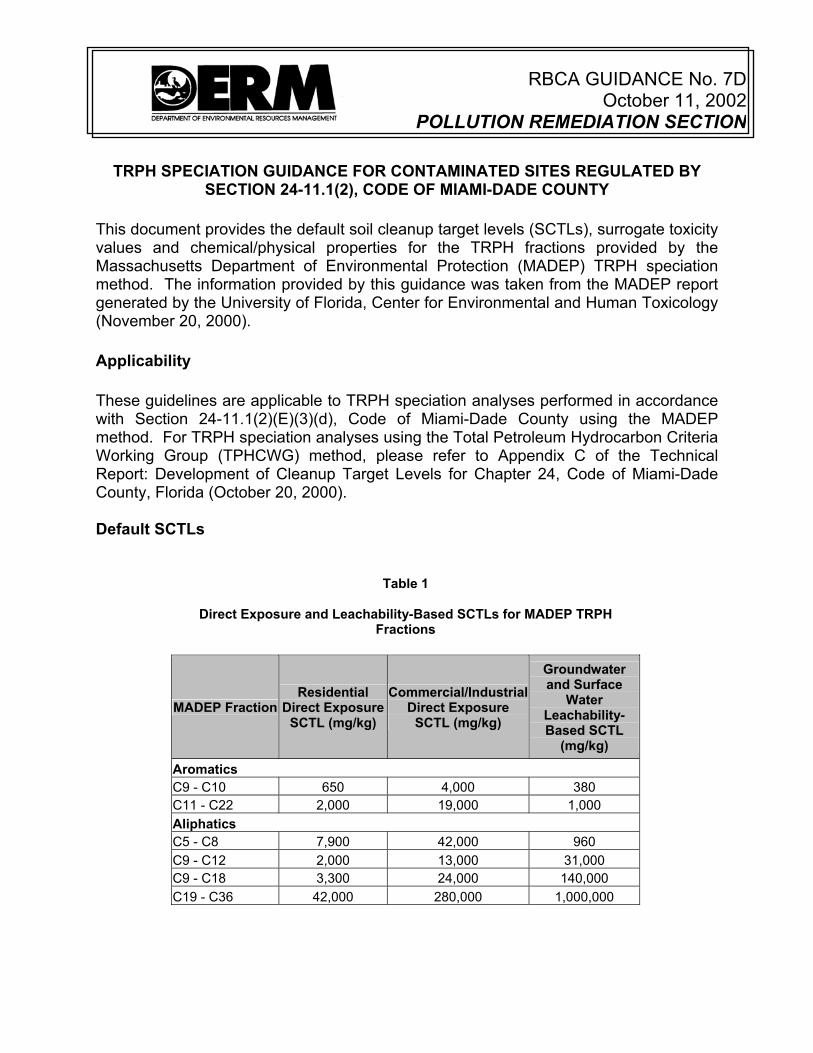
RBCA GUIDANCE No. 7D
October 11, 2002POLLUTION REMEDIATION SECTION
TRPH SPECIATION GUIDANCE FOR CONTAMINATED SITES REGULATED BY
SECTION 24-11.1(2), CODE OF MIAMI-DADE COUNTY This document provides the default soil cleanup target levels (SCTLs), surrogate toxicity values and chemical/physical properties for the TRPH fractions provided by the Massachusetts Department of Environmental Protection (MADEP) TRPH speciation method. The information provided by this guidance was taken from the MADEP report generated by the University of Florida, Center for Environmental and Human Toxicology (November 20, 2000). Applicability These guidelines are applicable to TRPH speciation analyses performed in accordance with Section 24-11.1(2)(E)(3)(d), Code of Miami-Dade County using the MADEP method. For TRPH speciation analyses using the Total Petroleum Hydrocarbon Criteria Working Group (TPHCWG) method, please refer to Appendix C of the Technical Report: Development of Cleanup Target Levels for Chapter 24, Code of Miami-Dade County, Florida (October 20, 2000). Default SCTLs
Table 1
Direct Exposure and Leachability-Based SCTLs for MADEP TRPH Fractions
MADEP Fraction Residential
Direct Exposure SCTL (mg/kg)
Commercial/Industrial Direct Exposure
SCTL (mg/kg)
Groundwater and Surface
Water Leachability-Based SCTL
(mg/kg) Aromatics C9 - C10 650 4,000 380 C11 - C22 2,000 19,000 1,000 Aliphatics C5 - C8 7,900 42,000 960 C9 - C12 2,000 13,000 31,000 C9 - C18 3,300 24,000 140,000 C19 - C36 42,000 280,000 1,000,000

TRPH Speciation Guidance October 11, 2002 Page 2 of 2
Chemical/Physical Properties and Toxicity Values for Use in Calculating Alternative SCTLs
Table 2
Reference Doses for Calculating Alternative SCTLs for MADEP TRPH Fractions
MADEP Fraction Oral Reference
Dose (mg/kg-day)
Dermal Reference Dose
(mg/kg-day)
Inhalation Reference Dose
(mg/kg-day) Aromatics C9 - C10 0.04 0.02 0.05714 C11 - C22 0.04 0.02 0.05714 Aliphatics C5 - C8 5.0 2.5 5.275 C9 - C12 0.1 0.05 0.2857 C9 - C18 0.1 0.05 0.2857 C19 - C36 2.0 1.0 1.0
Table 3
Chemical Physical Properties for MADEP TRPH Fractions
MADEP Fraction
Average Equivalent
Carbon Number
Molecular Weight (g/mol)
Vapor Pressure
(atm) Solubility
(mg/l)
Henry's Law
Constant (atm-
m3/mol)
Organic Carbon
Partition Coefficient
(mL/g)
Diffusivity (cm2/s)
Aromatics C9 - C10 9.5 120 2.9E-03 51 0.33 1,778 0.07 C11 - C22 14 150 3.2E-05 5.8 0.03 5,000 0.06 Aliphatics C5 - C8 6.5 94 1.0E-01 11 54 2,265 0.08 C9 - C12 10.5 149 8.7E-04 0.07 65 1.5E+05 0.07 C9 - C18 12 170 1.4E-04 0.01 69 6.8E+05 0.07 C19 - C36 18.5 270 1.1E-06 2.5E-06 4,900 6.3E+08 6.9E-06
RBCA GUIDANCE No. 7E
October 11, 2002POLLUTION REMEDIATION SECTION
OFF-SITE NOTIFICATION GUIDANCE FOR CONTAMINATED SITES REGULATED
BY SECTION 24-11.1(2), CODE OF MIAMI-DADE COUNTY
This document provides the party or parties responsible for site rehabilitation actions (SRAs) at a contaminated site with general guidelines for notifying owners, residents and tenants of properties onto which contamination has migrated from the source site. The notification requirements are set forth in Section 24-11.1(2)(I)(2), Code of Miami-Dade County (“the Code”). Applicability These guidelines apply to sites, at which SRAs in accordance with Section 24-11.1(2) of the Code are ongoing, where contamination has migrated beyond the site property boundaries. Although off-site contamination may exist temporarily while SRAs are ongoing, the cleanup target levels and conditions set forth in Section 24-11.1(2)(J)(1) of the Code must be achieved at the property boundaries prior to site closure (i.e., no further action or no further action with conditions). Notification Procedures Notification shall be given by the party or parties responsible for the SRAs within sixty (60) days of DERM’s approval of the site assessment report. The responsible party or parties shall provide actual notice to the owner(s) and constructive notice to residents and business tenants of any property into or onto which the contamination has extended. Actual notice shall be in written form and mailed by “Certified Mail, Return Receipt Requested” to the current real property owner(s) at the owner’s address listed in the County property tax roles. Constructive notice shall be achieved by 1) posting copies of the notice (at least 81/2 inches by 11 inches in size) in prominent common areas throughout the properties and 2) publishing the notice (at least 16 square inches in size) in a newspaper(s) of common circulation in the area affected by the contamination (e.g., the “Miami Herald,” appropriate ethnic newspapers, local community bulletins, etc.). Section 24-11.1(2)(I)(2) of the Code specifies the minimum information to be included in the notice and the timeframes for persons receiving notice to comment. A copy of the actual notice, the constructive notice and the published notice shall be submitted to DERM no later than ten (10) days after these notices are issued/published.
RBCA GUIDANCE No. 7F Revised October 3, 2013
Pollution Control Division Department of Permitting, Environment and Regulatory Affairs
INSTITUTIONAL CONTROL GUIDANCE FOR CONTAMINATED SITES REGULATED BY
SECTION 24-44(2), CODE OF MIAMI-DADE COUNTY
This document provides general guidelines for preparing an institutional control, in the form of
a covenant running with the land (“covenant”) and recorded in the public records of Miami-
Dade County, to qualify for a No Further Action (NFA) with conditions as set forth in Section
24-44 (2)(k)(ii), Code of Miami-Dade County (“the Code”). Institutional controls are restrictions
on the use of or access to a site to eliminate or manage exposure of human and environmental
receptors to contaminants of concern (COCs). Engineering controls, such as caps, barriers,
fences or slurry walls, may be used in conjunction with institutional controls to eliminate or
minimize exposure to or migration of COCs.
Applicability
These guidelines apply to contaminated sites at which the property owner(s) has/have elected
to implement an institutional control to qualify for an NFA with conditions.
Process Checklist
The following items shall be provided to the Department of Permitting, Environment and
Regulatory Affairs (hereinafter referred to as “Department”) for approval prior to recording the
covenant:
1. A draft (unsigned) copy of the proposed covenant, consistent with the covenant
template attached and available on the Department’s website. The covenant shall
include the following:
a. A copy of the legal description of the property (Exhibit A). If only a portion of
the site is to be restricted, then in addition to the legal description for the entire
property, a copy of either a survey or a legal description of that portion of the
site which is subject to the restrictions;
b. A summary of the contamination assessment report including summary table(s)
of analytical results, site map(s) (indicating the north direction, drawn to scale,
and including a graphical representation of the scale) with property boundaries,
institutional control boundaries, sample locations and sample results (Exhibit
B); and
Institutional Control Guidance Revised October 3, 2013 Page 2 of 3
c. If applicable, a summary of the Department-approved engineering control plan,
including the contaminant of concern plume map, drawn to scale, with the
engineering control superimposed and a detailed description of the
construction, maintenance, and, as appropriate, monitoring of the engineering
control (Exhibit C).
Additional guidance for covenant completion:
I. The owner(s) name on the proposed covenant must match the name of the current
property owner(s) at the time the covenant is filed in the public records.
II. The correct signature block on the covenant shall be selected (i.e., individual or
corporation), and the option not used shall be deleted. Note that if the property
owner is neither an individual nor a corporation (i.e., LLC, LLP, etc.), then the
covenant shall substitute the type of entity that owns the property. For all entities,
please indicate the state where the entity was formed and the required signatories,
as stated in the Opinion of Title.
III. Note that on the standard covenant form, the language within brackets shall be
modified, as appropriate; the language and format of the remaining portions of the
covenant should be consistent with the template covenant, except as provided
above with respect to the signature block.
2. A draft (unsigned) Opinion of Title. A sample Opinion of Title is attached. Note the
following:
a. A joinder must be provided for and executed by any person or entity who must
join (for example, a mortgage company), as specified in the Opinion of Title. All
required joinders must be recorded along with the restrictive covenant. The
joinder cannot be executed until there is a final version of the restricted covenant.
A sample Joinder is attached.
b. If an easement intersects with the restricted area, the Opinion of Title shall
identify what right(s) the easement holder has. Additionally, a scaled site
diagram shall be provided identifying the easement in reference to the restricted
area. If the restriction could affect or be affected by the easement holder’s rights,
then the owner will need to acquire a joinder.
c. Copies of all leases/subleases or assigned leases shall be provided along with
the Opinion of Title. Note that the conditions of the covenant may not conflict with
the rights of the leasees/tenants.
Institutional Control Guidance Revised October 3, 2013 Page 3 of 3
d. The Opinion of Title shall state who is authorized to sign the restrictive covenant
on behalf of each property owner.
e. The Opinion of Title shall be current (i.e., must be signed no more than 30 days
prior to the recording of the restrictive covenant).
Be advised that the covenant and opinion of title will be reviewed for legal sufficiency by the
Miami-Dade County Attorney’s Office before final approval.
After written approval of the covenant by the Department, the property owner executes the
covenant and records the fully executed covenant in the public records of Miami-Dade County.
A receipt (i.e., copy of the covenant stamped with the book and page number in the upper right
hand corner) indicating where and when the covenant was recorded shall be submitted to the
Department prior to issuance of the RBCA site closure permit and subsequently the NFA with
conditions letter.
If the covenant designates water supply well prohibitions, a copy of the recorded covenant
shall be submitted to the South Florida Water Management District and the Miami-Dade
County Health Department.
Enforcement of Controls
The RBCA site closure permit constitutes a lawful order of the Director of the Department and
provides the means by which the institutional and, if appropriate, engineering controls shall be
maintained and monitored. Compliance with the conditions of the permit and the covenant are
required by law and are necessary to protect human health and the environment. If conditions
of the permit or the covenant are violated, enforcement action may be initiated and, if
corrective action is not taken within thirty (30) days or as otherwise approved by the
Department, the NFA with conditions may be rescinded.
Removing Institutional and Engineering Controls
To remove an institutional or engineering control, the current property owner must submit a
written request to the Department with appropriate sampling data demonstrating that the
conditions set forth in Section 24-44 (2)(k)(i) of the Code have been achieved qualifying the
site for an NFA without conditions. If this is demonstrated to the satisfaction of the Department,
Director or the Director’s designee shall, as appropriate, modify or release the restrictive
covenant in accordance with Section 24-44 (2)(k)(ii) of the Code.
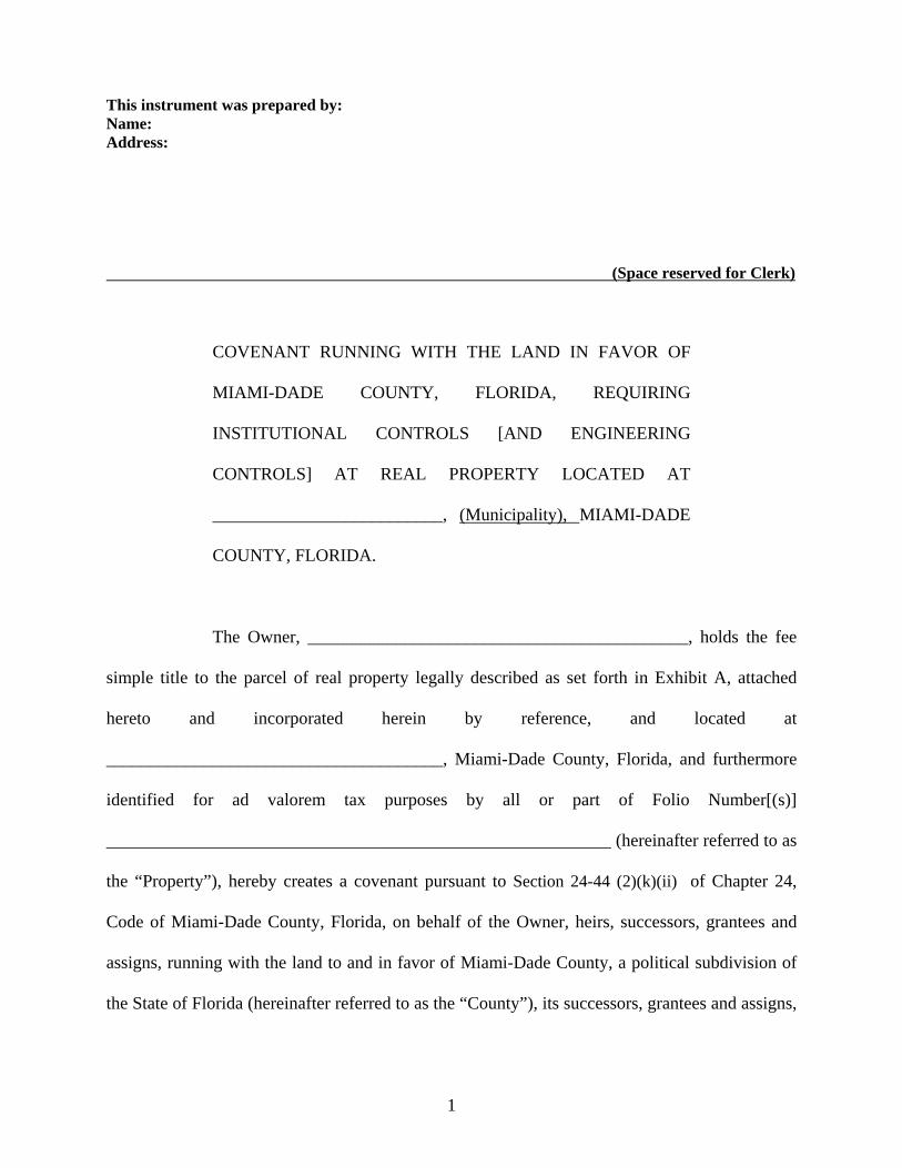
This instrument was prepared by: Name: Address:
(Space reserved for Clerk)
COVENANT RUNNING WITH THE LAND IN FAVOR OF
MIAMI-DADE COUNTY, FLORIDA, REQUIRING
INSTITUTIONAL CONTROLS [AND ENGINEERING
CONTROLS] AT REAL PROPERTY LOCATED AT
__________________________, (Municipality), MIAMI-DADE
COUNTY, FLORIDA.
The Owner, ___________________________________________, holds the fee
simple title to the parcel of real property legally described as set forth in Exhibit A, attached
hereto and incorporated herein by reference, and located at
______________________________________, Miami-Dade County, Florida, and furthermore
identified for ad valorem tax purposes by all or part of Folio Number[(s)]
_________________________________________________________ (hereinafter referred to as
the “Property”), hereby creates a covenant pursuant to Section 24-44 (2)(k)(ii) of Chapter 24,
Code of Miami-Dade County, Florida, on behalf of the Owner, heirs, successors, grantees and
assigns, running with the land to and in favor of Miami-Dade County, a political subdivision of
the State of Florida (hereinafter referred to as the “County”), its successors, grantees and assigns,
1
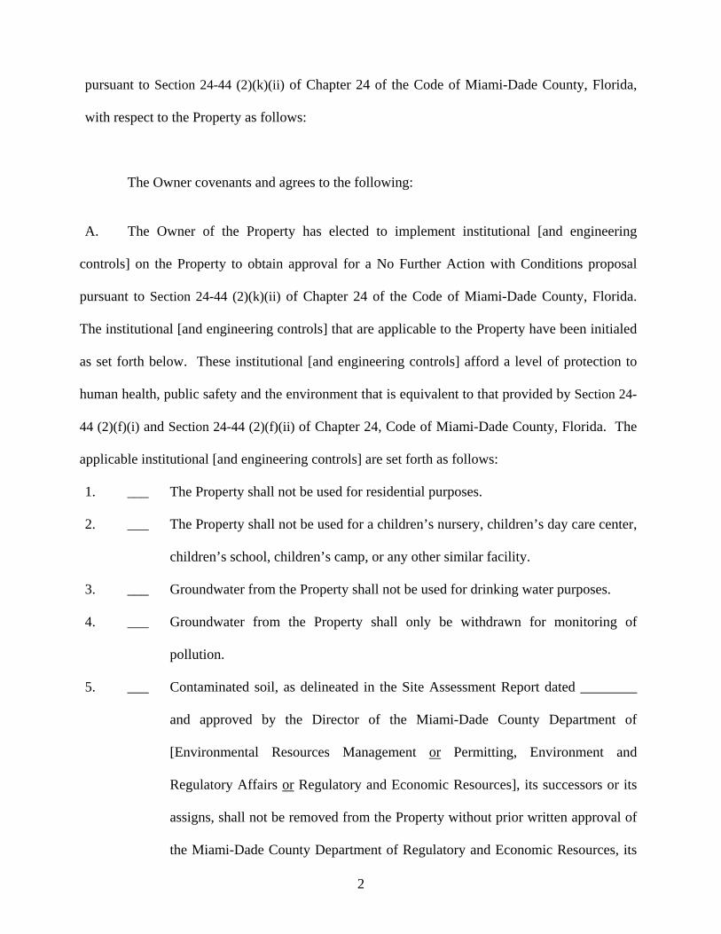
pursuant to Section 24-44 (2)(k)(ii) of Chapter 24 of the Code of Miami-Dade County, Florida,
with respect to the Property as follows:
The Owner covenants and agrees to the following:
A. The Owner of the Property has elected to implement institutional [and engineering
controls] on the Property to obtain approval for a No Further Action with Conditions proposal
pursuant to Section 24-44 (2)(k)(ii) of Chapter 24 of the Code of Miami-Dade County, Florida.
The institutional [and engineering controls] that are applicable to the Property have been initialed
as set forth below. These institutional [and engineering controls] afford a level of protection to
human health, public safety and the environment that is equivalent to that provided by Section 24-
44 (2)(f)(i) and Section 24-44 (2)(f)(ii) of Chapter 24, Code of Miami-Dade County, Florida. The
applicable institutional [and engineering controls] are set forth as follows:
1. ___ The Property shall not be used for residential purposes.
2. ___ The Property shall not be used for a children’s nursery, children’s day care center,
children’s school, children’s camp, or any other similar facility.
3. ___ Groundwater from the Property shall not be used for drinking water purposes.
4. ___ Groundwater from the Property shall only be withdrawn for monitoring of
pollution.
5. ___ Contaminated soil, as delineated in the Site Assessment Report dated ________
and approved by the Director of the Miami-Dade County Department of
[Environmental Resources Management or Permitting, Environment and
Regulatory Affairs or Regulatory and Economic Resources], its successors or its
assigns, shall not be removed from the Property without prior written approval of
the Miami-Dade County Department of Regulatory and Economic Resources, its
2

successors or its assigns. The Site Assessment report is summarized in Exhibit B,
which is incorporated by reference.
6. ___ Other applicable institutional controls as set forth below:
__________________________________________________________________
__________________________________________________________________
__________________________________________________________________
__________________________________________________________________
__________________________________________________________________
__________________________________________________________________
7. ___ Engineering control[(s)], detailed in the Engineering Control Plan dated
_________ and approved by the Director of the Miami-Dade County Department
of [Environmental Resources Management or Permitting, Environment and
Regulatory Affairs or Regulatory and Economic Resources], its successors or its
assigns. The Engineering Control Plan is summarized in Exhibit C, which is
incorporated by reference.
B. Prior to the entry into a landlord-tenant relationship with respect to the Property,
the Owner agrees to notify in writing all proposed tenants of the Property of the existence
and contents of this Covenant.
C. For the purpose of inspecting for compliance with the institutional [and
engineering controls] contained herein, the Miami-Dade County Department of
Regulatory and Economic Resources, its successors or its assigns, shall have access to the
Property at reasonable times and with reasonable notice to the Owner of the Property. In
3
the event that the Owner does not or will not be able to comply with any of the
institutional [and engineering controls] contained herein, the Owner shall notify in
writing the Miami-Dade County Department of Regulatory and Economic Resources, its
successors or its assigns, within three (3) calendar days.
D. This Covenant may be enforced by the Director of the Miami-Dade County
Department of Regulatory and Economic Resources, its successors or its assigns, by
permanent, temporary, prohibitory, and mandatory injunctions as well as otherwise
provided for by law or ordinance.
E. The provisions of this instrument shall constitute a covenant running with the
land, shall be recorded, at the Owner’s expense, in the public records of Miami-Dade
County and shall remain in full force and effect and be binding upon the undersigned,
their heirs, legal representatives, estates, successors, grantees and assigns until a release
of this Covenant is executed and recorded in the Public Records of Miami-Dade County,
Florida.
F. This Covenant is to run with the land and shall be binding on all parties and all
persons claiming under it for a period of thirty (30) years after the date this Covenant is
recorded, after which time it shall be extended automatically for successive periods of ten
(10) years each, unless the Covenant is modified or released by Miami-Dade County.
G. Upon demonstration to the satisfaction of the Director of the Department of
Regulatory and Economic Resources, its successors or its assigns, that the institutional
4
controls [and engineering controls] set forth in this Covenant are no longer necessary for
the purposes herein intended because the criteria set forth in Section 24-44 (2)(k)(i) of
Chapter 24 of the Code of Miami-Dade County, Florida have been met, the Director of
the Department of Regulatory and Economic Resources, its successors or its assigns,
shall, upon written request of the Owner, release this Covenant.
H. The Owner shall notify the Director of the Miami-Dade County Department of
Regulatory and Economic Resources, its successors or its assigns, within thirty (30) days
of any conveyance, sale, granting or transfer of the Property or portion thereof, to any
heirs, successors, assigns or grantees, including, without limitation, the conveyance of
any security interest in said Property.
I. The term Owner shall include the Owner and its heirs, successors and assigns.
IN WITNESS WHEREOF, the undersigned, being the Owner of the Property,
agrees to the provisions of this Covenant, hereby create same as a Covenant Running
with the Land in favor of Miami-Dade County, Florida, and set their hands and seal unto
this Covenant this ______ day of __________________, _______.
INDIVIDUAL WITNESSES: OWNER: sign __________________________________ sign __________________________ print __________________________________ print _________________________ sign __________________________________ Address ______________________ print __________________________________ ______________________ STATE OF FLORIDA COUNTY OF MIAMI-DADE
5
6
The foregoing instrument was acknowledged before me this ______________ day of __________________________, _______ by ________________________________, who is personally known to me or who has produced _________________________________ as identification and who did take an oath. NOTARY PUBLIC: sign _________________________ print _________________________ State of Florida at Large (Seal) My Commission Expires: _____ IN WITNESS WHEREOF, the undersigned, being the Owner of the Property, agrees to the terms of this Covenant, hereby create same as a Covenant Running with the Land, and set their hands and seal unto this Covenant this ________ day of ___________________, ______. CORPORATION WITNESSES: sign ______________________________ Corporation _____________________, Inc. print ______________________________ sign _______________________________ sign ______________________________ print _______________________________ print ______________________________ Title _______________________________ sign ______________________________ Address ____________________________ print ______________________________ (corporate seal) STATE OF FLORIDA COUNTY OF MIAMI-DADE The foregoing instrument was acknowledged before me this ______________ day of ______________________, ______ by _____________________________, as _____________________________ of _______________________________, Inc., a Florida corporation, on behalf of the corporation. He or she is personally known to me or has produced _____________________________ as identification and who take an oath. NOTARY PUBLIC: sign _______________________________ print _______________________________ State of Florida at Large (Seal) My Commission Expires: ___________

I am of the opinion that on the last mentioned date, the fee simple title to the above-described real property was vested in:
Note: For Limited Partnership, Limited Liability Company or Joint Venture indicate parties comprising the Limited Partnership, Limited Liability Company or Joint Venture and identify who is authorized to execute.
Subject to the following encumbrances, liens and other exceptions (If "none" please indicate):
OPINION OF TITLE
To: Miami-Dade County
With the understanding that this Opinion of Title is furnished to Miami-Dade County, as inducement for acceptance of a Covenant Running With the Land pursuant to Chapter 24, Code of Miami-Dade County, covering the real property, hereinafter described, it is hereby certified that I have examined a complete Abstract of Title covering the period from the beginning to the _________ day of _________________________, ______, at the hour of ___________________________, inclusive, of the following described property:
1. RECORDED MORTGAGES:
2. RECORDED CONSTRUCTION LIENS, CONTRACT LIENS AND JUDGMENTS:
3. GENERAL EXCEPTIONS:
4. SPECIAL EXCEPTIONS:

I HEREBY CERTIFY that I have reviewed all the aforementioned encumbrances and exceptions and that none of them hinder or affect the recording or enforcement of the _________________________.
Therefore, it is my opinion that the following party(ies) must join in the agreement in order to make the ___________ a valid and binding covenant on the lands described herein.
Name Interest Special Exception Number
The following is a description of the aforementioned abstract and its continuations:
Number Company Certifying No. of Entries Period Covered
I HEREBY CERTIFY that the legal description contained in this Opinion of Title coincides with, and is the same as, the legal description in the proffered, recordable agreement.
I, the undersigned, further certify that I am an attorney-at-law duly admitted to practice in the State of Florida and a member in good standing of the Florida Bar.
Respectfully submitted this ________ day of __________________, _______. _________________________________
Name
_________________________________
Print Name
Florida Bar No. ___________________
Address:
________________________________
________________________________
STATE OF FLORIDA
COUNTY OF MIAMI-DADE
The foregoing instrument was acknowledged before me this ______ day of ____________________________, ______, by _______________________________, who is personally known to me or has produced ______________________________, as identification.
_________________________________
Notary Public
_________________________________
My Commission Expires: Print Name

(Space reserved for Clerk)
JOINDER BY MORTGAGEE
CORPORATION The undersigned ___________________________________, a ____________________ (state) corporation and Mortgagee under that certain mortgage from ____________________________ ________________________________ dated the ______ day of _________________________, _______, and recorded in Official Records Book ______________, Page _____________, of the Public Records of Miami-Dade County, Florida, covering all/or a portion of the property described in the foregoing agreement, does hereby acknowledge that the terms of this agreement are and shall be binding upon the undersigned and its successors in title. IN WITNESS WHEREOF, these presents have been executed this __________ day of _________________________, ________.
Witnesses: _____________________________ __________________________________
Signature Name of Corporation _____________________________ Address: Print Name __________________________________ _____________________________ __________________________________ Signature __________________________________ _____________________________ By _______________________________
Print Name (President, Vice-President or CEO*)
Print Name: _______________________
[*Note: All others require attachment of original
corporate resolution of authorization]
STATE OF ____________________
COUNTY OF __________________ The foregoing instrument was acknowledged before me by ________________________ (Name)
the ______________________________ of ____________________________ corporation, on (Title) (Name)
behalf of the corporation. He/She is personally known to me or has produced ___________________________, as identification.
Witness my signature and official seal this ______ day of _____________________________, _________, in the County and State aforesaid.
_____________________________________ (Signature)
Notary Public-State of ___________________
_____________________________________ (Print Name)
My Commission Expires: _________________
[f:\forms\Joinder by Mortgagee Corporation.doc (9/9/04)]