quick start guides - carlson software
TRANSCRIPT
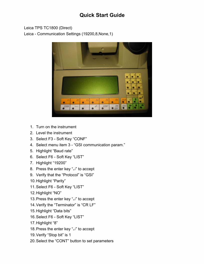
Quick Start Guide Leica TPS TC1800 (Direct) Leica - Communication Settings (19200,8,None,1)
1. Turn on the instrument 2. Level the instrument 3. Select F3 - Soft Key “CONF” 4. Select menu item 3 - “GSI communication param.” 5. Highlight “Baud rate” 6. Select F6 - Soft Key “LIST” 7. Highlight “19200” 8. Press the enter key “↵” to accept 9. Verify that the “Protocol” is “GSI” 10. Highlight “Parity” 11. Select F6 - Soft Key “LIST” 12. Highlight “NO” 13. Press the enter key “↵” to accept 14. Verify the “Terminator” is “CR LF” 15. Highlight “Data bits” 16. Select F6 - Soft Key “LIST” 17. Highlight “8” 18. Press the enter key “↵” to accept 19. Verify “Stop bit” is 1 20. Select the “CONT” button to set parameters

21. Select F6 - Soft Key “MEAS” 22. In SurvCE, select the “Leica TPS Series” driver from “Equip Instrument” 23. Verify the SurvCE communication settings by selecting “Equip Comm Setup”
(This only needs to be set the first time you use this equipment)
24. Set “Equip Settings” as shown below:
25. Select the “OK” button

Quick Start Guide Leica TPS TCA1800 (Remote) Leica - Communication Settings (19200,8,None,1)
1. Turn on the instrument 2. Level the instrument 3. Select F3 - Soft Key “CONF” 4. Select menu item 4 - “GeoCOM communication param.” 5. Highlight “Baud rate” 6. Select F6 - Soft Key “LIST” 7. Highlight “19200” 8. Press the enter key “↵” to accept 9. Verify that the “Protocol” is “GeoCOM” 10. Highlight “Parity” 11. Select F6 - Soft Key “LIST” 12. Highlight “NO” 13. Press the enter key “↵” to accept 14. Verify the “Terminator” is “CR LF” 15. Highlight “Data bits” 16. Select F6 - Soft Key “LIST” 17. Highlight “8” 18. Press the enter key “↵” to accept 19. Verify “Stop bit” is 1 20. Select the “CONT” button to set parameters

21. Select F1 - Soft Key “EXTRA” 22. Select menu item 1 - “On-Line mode <GeoCOM> 23. Select F5 - Soft Key “YES” 24. In SurvCE, select the “Leica Robotic Instrument” driver from “Equip
Instrument” 25. Verify the SurvCE communication settings by selecting “Equip Comm Setup”
(This only needs to be set the first time you use this equipment)
26. Set “Equip Settings” as shown below:
27. Select the “OK” button
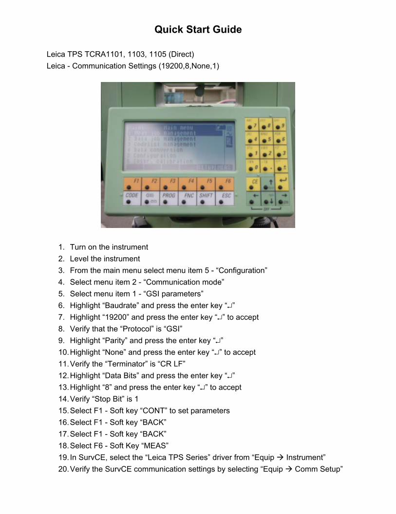
Quick Start Guide Leica TPS TCRA1101, 1103, 1105 (Direct) Leica - Communication Settings (19200,8,None,1)
1. Turn on the instrument 2. Level the instrument 3. From the main menu select menu item 5 - “Configuration” 4. Select menu item 2 - “Communication mode” 5. Select menu item 1 - “GSI parameters” 6. Highlight “Baudrate” and press the enter key “↵” 7. Highlight “19200” and press the enter key “↵” to accept 8. Verify that the “Protocol” is “GSI” 9. Highlight “Parity” and press the enter key “↵” 10. Highlight “None” and press the enter key “↵” to accept 11. Verify the “Terminator” is “CR LF” 12. Highlight “Data Bits” and press the enter key “↵” 13. Highlight “8” and press the enter key “↵” to accept 14. Verify “Stop Bit” is 1 15. Select F1 - Soft key “CONT” to set parameters 16. Select F1 - Soft key “BACK” 17. Select F1 - Soft key “BACK” 18. Select F6 - Soft Key “MEAS” 19. In SurvCE, select the “Leica TPS Series” driver from “Equip Instrument” 20. Verify the SurvCE communication settings by selecting “Equip Comm Setup”

(This only needs to be set the first time you use this equipment)
21. Set “Equip Settings” as shown below. If the instrument has any of the options shown in the dialog below, select as desired. Make sure “Powersearch” enabled machines have this option selected and instruments without “Powersearch” do not.
22. Select the “OK” button

Quick Start Guide Leica TPS TCRA1101, 1103, 1105 (Robotic) Leica - Communication Settings (19200,8,None,1)
1. Turn on the instrument 2. Level the instrument 3. From the main menu select menu item 5 - “Configuration” 4. Select menu item 2 - “Communication mode” 5. Select menu item 2 - “GeoCOM parameters” 6. Highlight “Baudrate” and press the enter key “↵” 7. Highlight “19200” and press the enter key “↵” to accept 8. Verify that the “Protocol” is “GeoCOM” 9. Highlight “Parity” and press the enter key “↵” 10. Highlight “None” and press the enter key “↵” to accept 11. Verify the “Terminator” is “CR LF” 12. Highlight “Data Bits” and press the enter key “↵” 13. Highlight “8” and press the enter key “↵” to accept 14. Verify “Stop Bit” is 1 15. Select F1 - Soft key “CONT” to set parameters 16. Select menu item 3 - “GeoCOM On-Line mode” 17. At the prompt “Do you want to switch?”, select F4 - Soft key “YES” 18. In SurvCE, select the “Leica Robotic Instrument” driver from “Equip
Instrument” 19. Verify the SurvCE communication settings by selecting “Equip Comm Setup”

(This only needs to be set the first time you use this equipment)
20. Set “Equip Settings” as shown below. If the instrument has any of the options shown in the dialog below, select as desired. Make sure “Powersearch” enabled machines have this option selected and instruments without “Powersearch” do not.
28. Select the “OK” button

Quick Start Guide Trimble 5600 DR200+ (Station Mode) - Firmware version 696-03.05 To check firmware version, Menu 5, 4, 1 Trimble - Communication Settings (9600,8,None,1)
1. Turn on the instrument 2. Level the instrument If communication settings need to be set continue with step 3, if not, go to measurement screen. 3. Select MNU, ENT, 4 (Data com), 1 (Select device), 2 (Serial) 4. At prompt “Serial ON?”, select ENT 5. Verify COM=1.8.0.9600 followed by ENT 6. At prompt “Table no=”, select ENT 7. At prompt “Length=”, do what’s right and get back to the measure screen 8. In SurvCE, select the Trimble 5600 driver from “Equip Instrument”
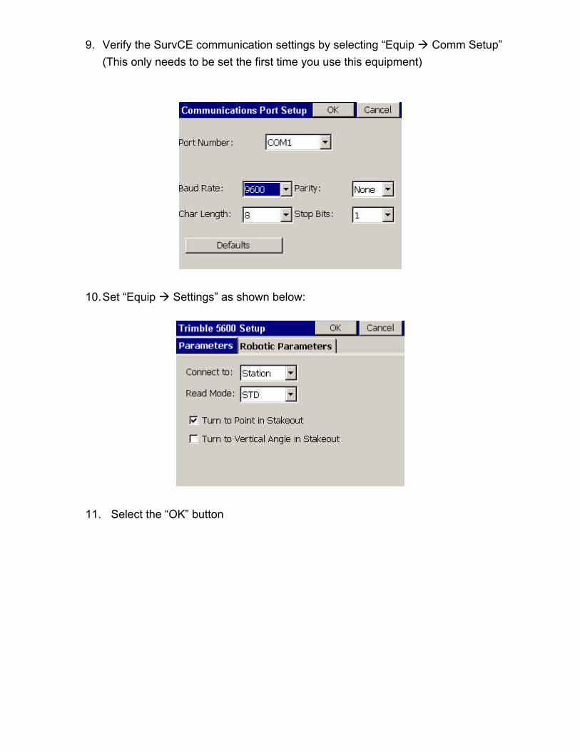
9. Verify the SurvCE communication settings by selecting “Equip Comm Setup” (This only needs to be set the first time you use this equipment)
10. Set “Equip Settings” as shown below:
11. Select the “OK” button

Quick Start Guide Trimble 5600 DR200+ (Robotic Mode) - Firmware version 696-03.05 To check firmware version, Menu 5, 4, 1 Trimble - Communication Settings (9600,8,None,1)
1. Turn on the instrument 2. Level the instrument and allow instrument to compensate If communication settings need to be set continue with step 3, if not, go to step 7. 3. Select MNU, ENT, 4 (Data com), 1 (Select device), 2 (Serial) 4. At prompt “Serial ON?”, select ENT 5. Verify COM=1.8.0.9600 followed by ENT 6. At prompt “Table no=”, select ENT 7. Select the RPU button on the instrument and select 3 for Remote 8. Once the instrument shuts down in remote mode, remove the faceplate 9. Make sure the handheld is on and SurvCE is running 10. In SurvCE, select the “Trimble 5600” driver from “Equip Instrument” 11. Verify the SurvCE communication settings by selecting “Equip Comm Setup”
(This only needs to be set the first time you use this equipment)

12. Set “Equip Settings” as shown below. The radio channel and station addresses are user definable. The “Connect to: Direct Robotic” option allows the instrument to work exactly like it does with the GeoRadio but allows the user to connect using a cable instead of the radio.
13. Select the “Initialize GeoRadio” or “Initialize Instrument” button shown above. 14. Select the “OK” button.
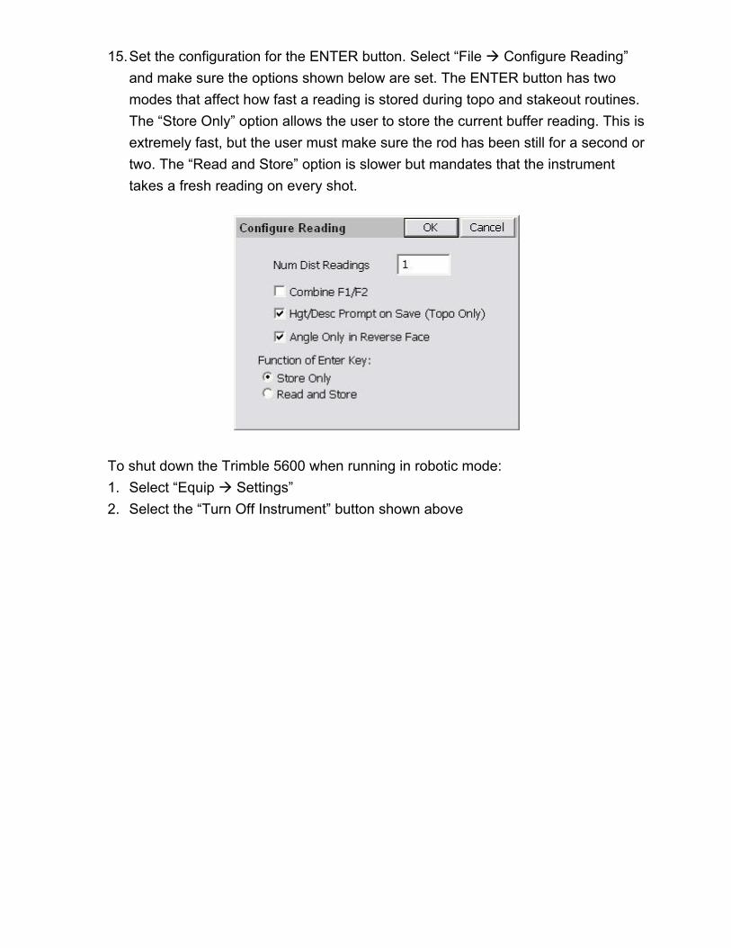
15. Set the configuration for the ENTER button. Select “File Configure Reading” and make sure the options shown below are set. The ENTER button has two modes that affect how fast a reading is stored during topo and stakeout routines. The “Store Only” option allows the user to store the current buffer reading. This is extremely fast, but the user must make sure the rod has been still for a second or two. The “Read and Store” option is slower but mandates that the instrument takes a fresh reading on every shot.
To shut down the Trimble 5600 when running in robotic mode: 1. Select “Equip Settings” 2. Select the “Turn Off Instrument” button shown above

Quick Start Guide Topcon GTS-802A (Direct) Topcon GTS-802A communication settings (19200,8,None,1)
1. Turn on instrument 2. Level the instrument If the communication parameters need to be set, proceed with step 3, if not, go to step 21. 3. From the main menu screen, select F6 - Soft Key “Para” 4. Select F2 - Soft Key “Communication” 5. Select 1 “Serial Port” 6. Select “RS232C” 7. Select F1 - Soft Key “Set” 8. At prompt “Parameters - Set OK?”, select F5 - Soft Key “YES” 9. Select 2 “Set RS232C” 10. Set “B. Rate” to “9600” followed by the ENT button 11. Set “Data L.” to “8” followed by the ENT button 12. Set “Parity” to “None” followed by the ENT button 13. Set “Stop Bit” to “1” followed by the ENT button 14. Set “Delimit” to “CRLF” followed by the ENT button 15. Set “REC-A/B” to “A” followed by the ENT button 16. Set “Protocol” to “On” followed by the ENT button

17. Set “NEZ-REC” to “Std” followed by the ENT button 18. Set “TrkState” to “Off” followed by the ENT button 19. At prompt “Parameters - Set OK?”, select F5 - Soft Key “YES” 20. ESC to main menu 21. From the main menu, Select F2 - Soft Key “STD” 22. Select the “Topcon 800 Direct” driver from “Equip Instrument” 23. Verify the SurvCE communication settings by selecting “Equip Comm Setup”
(This only needs to be set the first time you use this equipment)
24. Set “Equip Settings” as shown below (Fine, Course and Track are optional)
25. Select the “OK” button
Quick Start Guide Angle sets with the Trimble 5600 (Station mode) Note: When using “Station” mode, the faceplate must be on the instrument. SurvCE can only perform angle sets using “Set Collection” with the Trimble 5600 if the following settings and procedures are followed.
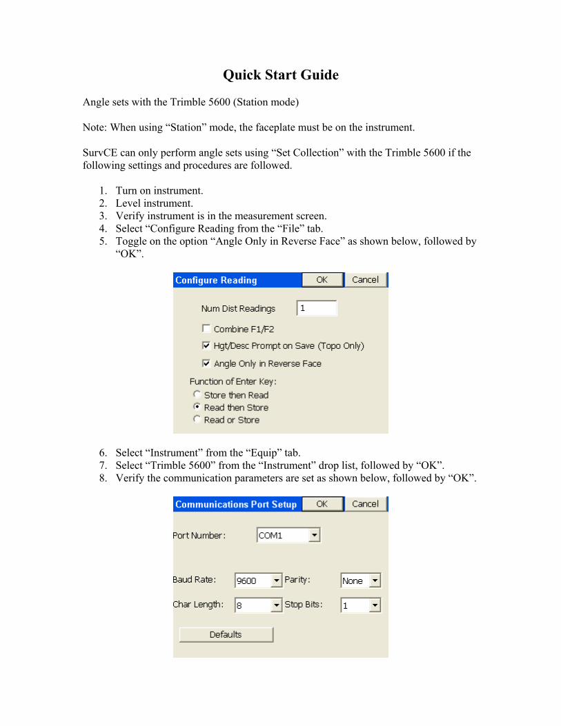
1. Turn on instrument. 2. Level instrument. 3. Verify instrument is in the measurement screen. 4. Select “Configure Reading from the “File” tab. 5. Toggle on the option “Angle Only in Reverse Face” as shown below, followed by
“OK”.
6. Select “Instrument” from the “Equip” tab. 7. Select “Trimble 5600” from the “Instrument” drop list, followed by “OK”. 8. Verify the communication parameters are set as shown below, followed by “OK”.
9. Select “Settings” from the “Equip” tab and configure as shown below, followed
by “OK”.
10. Select “Set Collection” from “Surv” tab. 11. At the confirm orientation dialog, select “No”. 12. In the “Instrument Setup” dialog, key in the occupied point ID, instrument height,
backsight point ID and the backsight target height. Note that the backsight point ID must be entered even if the backsight point does not exist.
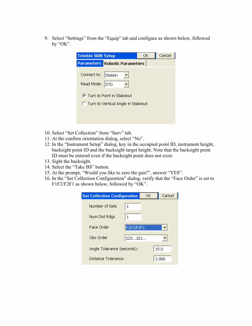
13. Sight the backsight. 14. Select the “Take BS” button. 15. At the prompt, “Would you like to zero the gun?”, answer “YES”. 16. In the “Set Collection Configuration” dialog, verify that the “Face Order” is set to
F1F2/F2F1 as shown below, followed by “OK”.

17. In the “Set Collection Point Order” dialog, key in the foresight point ID’s into the input boxes starting with the top left input box working down and to the right as shown below followed by “OK”.
In this example the user will sight the points in the following order:
• BS Direct 2 • FS Direct 1005 • FS Direct 3 • FS Reverse 3 • FS Reverse 1005 • BS Reverse 2
18. At the resulting dialog shown below, enter in the backsight target height and press enter on the keyboard or select “OK” to read the instrument.
19. At the “Shot Review” dialog, verify the data is correct and answer “YES” to
continue.
20. At the next dialog, enter in the foresight target height, sight the foresight point and press enter to read the instrument.
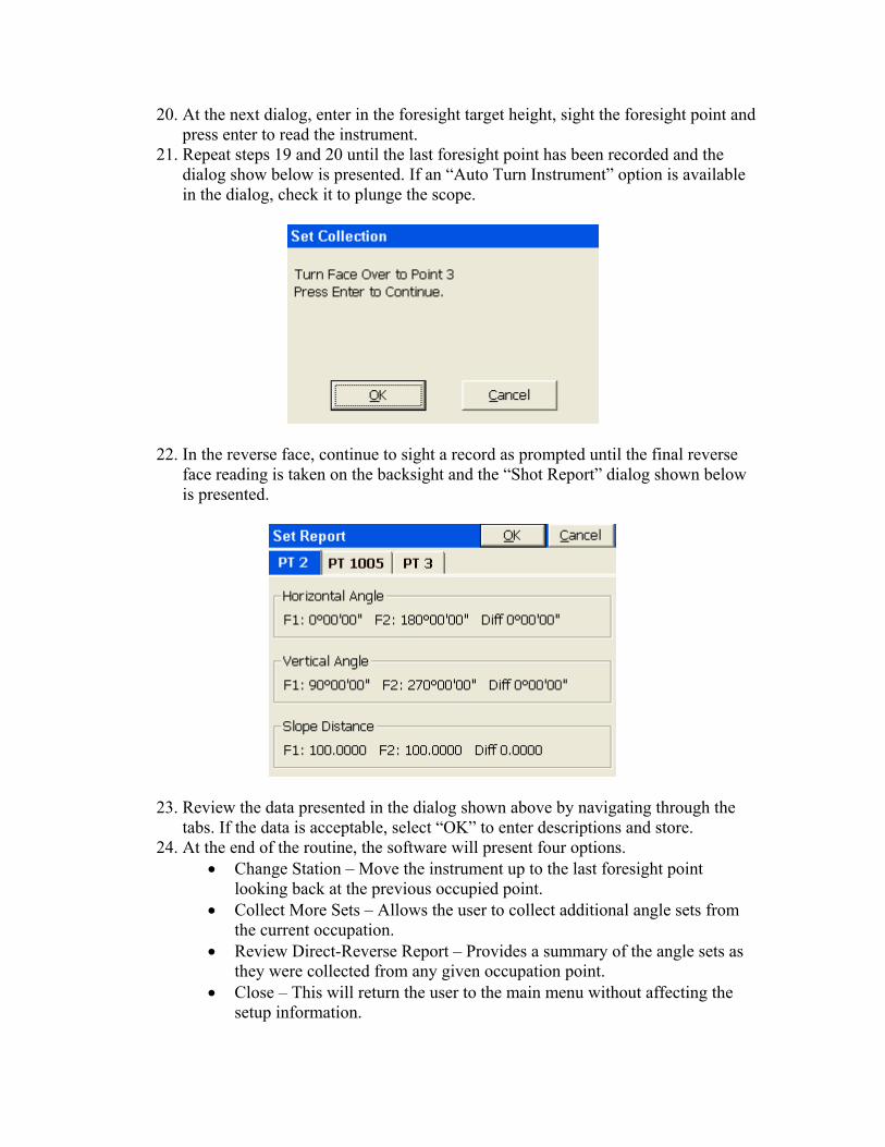
21. Repeat steps 19 and 20 until the last foresight point has been recorded and the dialog show below is presented. If an “Auto Turn Instrument” option is available in the dialog, check it to plunge the scope.
22. In the reverse face, continue to sight a record as prompted until the final reverse face reading is taken on the backsight and the “Shot Report” dialog shown below is presented.
23. Review the data presented in the dialog shown above by navigating through the tabs. If the data is acceptable, select “OK” to enter descriptions and store.
24. At the end of the routine, the software will present four options. • Change Station – Move the instrument up to the last foresight point
looking back at the previous occupied point. • Collect More Sets – Allows the user to collect additional angle sets from
the current occupation. • Review Direct-Reverse Report – Provides a summary of the angle sets as
they were collected from any given occupation point. • Close – This will return the user to the main menu without affecting the
setup information.

Quick Start Guide Trimble 4800 GPS used as Base with External Pacific Crest PDL Radio The Trimble 4800 can be operated as a base station using a Pacific Crest PDL radio. The following settings must be applied.
1. Verify that the base and rover radios are programmed to communicate as follows: a. Over-the-air baud rate = 9600 b. Trimtalk Mode c. Turn off scrambling. d. Verify frequencies match between the base and rover.
2. Connect the PDL radio to the 4800 using a serial cable. This can be put together by using a DB9 to Trimble data collector cable, a null modem adapter and a gender changer connected to the PDL DB9 programming cable.
3. Turn on the 4800 and the PDL. 4. From the “Equip” tab in SurvCE, select the “Instrument” button and choose
“Trimble GPS General”. 5. When prompted for the “Communication Port Setup”, set the parameters as
shown below, followed by “OK”.

6. Select “Configure Base” from the “Equip” tab and set the parameters as shown below, followed by “OK”.
7. At the “Base Configuration” dialog, complete the base setup as needed. Make sure that you do not enter a “Reference Station ID” when prompted. Leave the input box blank and select “OK” to continue.
8. SurvCE should connect to the receiver and the radio should begin broadcasting corrections. If you receive an error message, go back into “Configure Base” and select “OK” and repeat step 7.