quartz: a new design element for low-latency dcns
TRANSCRIPT
Quartz: A New Design Element for Low-Latency DCNs
Yunpeng James LiuUniversity of Waterloo
Peter Xiang GaoUC Berkeley
[email protected] Wong
University of [email protected]
Srinivasan KeshavUniversity of Waterloo
ABSTRACTMost datacenter network (DCN) designs focus on maximizing bi-section bandwidth rather than minimizing server-to-server latency.We explore architectural approaches to building low-latency DCNsand introduce Quartz, a design element consisting of a full meshof switches. Quartz can be used to replace portions of either ahierarchical network or a random network. Our analysis showsthat replacing high port-count core switches with Quartz can sig-nificantly reduce switching delays, and replacing groups of top-of-rack and aggregation switches with Quartz can significantly re-duce congestion-related delays from cross-traffic. We overcome thecomplexity of wiring a complete mesh using low-cost optical mul-tiplexers that enable us to efficiently implement a logical mesh as aphysical ring. We evaluate our performance using both simulationsand a small working prototype. Our evaluation results confirm ouranalysis, and demonstrate that it is possible to build low-latencyDCNs using inexpensive commodity elements without significantconcessions to cost, scalability, or wiring complexity.
Categories and Subject DescriptorsC.2.1 [Network Architecture and Design ]: Network topology
KeywordsOptical Technologies; WDM; Datacenter; Latency
1. IntroductionNetwork latency is a critical factor in determining the perfor-
mance of many datacenter-scale, distributed applications. For ex-ample, in most distributed realtime computation frameworks suchas MPI [24] and Storm [13], network latency manifests as a sub-stantial component of coordination delay and is therefore on thecritical path. In realtime or interactive applications such as searchengines, social networks, and high frequency financial trading, awide-area request may trigger hundreds of message exchanges in-side a datacenter. For example, in a measurement study from Face-book, servicing a remote HTTP request can require as many as 88cache lookups, 35 database lookups, and 392 backend remote pro-cedure calls [23]. Therefore, there is an urgent, market-driven needfor reducing network latency.
Permission to make digital or hard copies of all or part of this work for personal orclassroom use is granted without fee provided that copies are not made or distributedfor profit or commercial advantage and that copies bear this notice and the full cita-tion on the first page. Copyrights for components of this work owned by others thanACM must be honored. Abstracting with credit is permitted. To copy otherwise, or re-publish, to post on servers or to redistribute to lists, requires prior specific permissionand/or a fee. Request permissions from [email protected]’14, August 17–22, 2014, Chicago, IL, USA.Copyright 2014 ACM 978-1-4503-2836-4/14/08 ...$15.00.http://dx.doi.org/10.1145/2619239.2626332 .
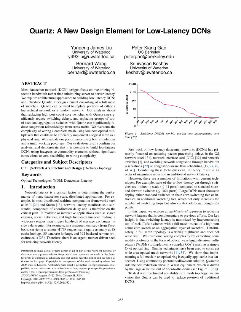
Figure 1: Backbone DWDM per-bit, per-km cost improvements overtime [20].
Past work on low-latency datacenter networks (DCNs) has pri-marily focussed on reducing packet processing delays in the OSnetwork stack [31], network interface card (NIC) [32] and networkswitches [3], and avoiding network congestion through bandwidthreservations [29] or congestion-aware flow scheduling [19, 27, 40,41, 43]. Combining these techniques can, in theory, result in anorder of magnitude reduction in end-to-end network latency.
However, there are a number of limitations with current tech-niques. For example, state-of-the-art low-latency cut-through swit-ches are limited in scale (≤ 64 ports) compared to standard store-and-forward switches (≤ 1024 ports). Large DCNs must choose todeploy either standard switches in their core-switching tier or in-troduce an additional switching tier, which not only increases thenumber of switching hops but also creates additional congestionpoints.
In this paper, we explore an architectural approach to reducingnetwork latency that is complementary to previous efforts. Our keyinsight is that switching latency is minimized by interconnectingtop-of-rack (ToR) switches with a full mesh instead of a high-portcount core switch or an aggregation layer of switches. Unfortu-nately, a full mesh topology is a wiring nightmare and does notscale well. We overcome wiring complexity by exploiting com-modity photonics in the form of optical wavelength division multi-plexers (WDMs) to implement a complex O(n2) mesh as a simpleO(n) optical ring. Similar techniques have been used to constructwide-area optical mesh networks [11, 34]. We show that imple-menting a full mesh in an optical ring is equally applicable in a dat-acenter. Using commodity photonics allows our solution, Quartz toride the cost reduction curve in WDM equipment, which is drivenby the large-scale roll out of fiber-to-the-home (see Figure 1 [20]).
To deal with the limited scalability of a mesh topology, we en-vision that Quartz can be used to replace portions of traditionalDCNS:
283
Component Standard State of ArtOS Network Stack 15µs [36] 1 - 4 µs [31]
NIC 2.5 - 32µs [36] 0.5µs [32]Switch 6 µs [5] 0.5µs [3]
Congestion 50µs [31]Table 2: Network latencies of different network components.
• Replacing large top-of-rack (ToR) switches in single-tier net-works with a single Quartz mesh to reduce latency and allowincremental upgrades.
• Replacing both ToR and aggregation switches in a standard3-tier network with a single Quartz tier to significantly re-duce the impact of cross-traffic.
• Replacing core switches to provide a large-scale, low-latency,and incrementally upgradable core switching tier.
• Replacing sets of switches in a randomized DCN [37, 38] toprovide lower latency for traffic with strong locality.
We evaluate Quartz through both simulations using a packet-level simulator and experiments on a working prototype consist-ing of four switches and six WDM muxes/demuxes. Our resultsdemonstrate that Quartz can significantly reduce both switchingand queuing latencies on various application workloads. We evalu-ate the cost of Quartz and show that it is cost competitive for manydeployment scenarios. Moreover, we expect the cost of our solutionto diminish over time as WDM shipping volumes rise.
Overall, our work makes three contributions:
• We present a novel use of commodity photonics in DCNsto build Quartz, a WDM-based design element for reducingcommunication latency.
• We show how Quartz can be used in different topologies toreduce latency and congestion.
• We evaluate performance using both simulations and a smallworking prototype and find that Quartz can reduce latency by50% in many scenarios.
2. Background and Related WorkThis section describes the different sources of network latency
and the previous work to address each source. It also introducesthe optical network technologies used in Quartz.
2.1 Sources of LatencyThere are many sources of latency in DCNs (see Table 2 for a
summary). We discuss each in turn.
2.1.1 Network StackPackets often need to wait for one or more context switches be-
fore they are received by a user-space application. Techniques suchas kernel bypass and zero-copy processing can reduce this latency.In recent work, the Chronos [31] system uses these techniques tosignificantly reduce the operating system kernel latency for data-center applications.
2.1.2 Network Interface CardsCommodity Network Interface Cards (NICs) can introduce tens
of microseconds of latency from performing basic buffering andpacket processing. Recent work shows that by offloading packetprocessing to a FPGA and optimizing the communication betweenthe FPGA and the host processor, NIC latency can be reduced to
hundreds of nanoseconds [32]. Alternatively, RDMA over Infini-band or Ethernet [28] can reduce latency by eliminating communi-cation between the NIC and the host processor for certain opera-tions.
2.1.3 Switch LatencySwitching delay is a significant source of network latency. For
example, the Cisco Catalyst 4948 10 Gigabit Ethernet Switch, whichis commonly used in modern datacenters, has a switching latency ofat least 6µs. In a typical three-tier network architecture, switchingdelay can therefore be as high as 30µs. Switching delay can be re-duced by having fewer network tiers, and adopting low-latency cut-through switches. Unlike store-and-forward switches, cut-throughswitches start to send a frame before fully receiving it. Low-latencyswitches, such as the Arista 7100 [3], have a switching delay of ap-proximately 500 ns. Cut-through switches command only a smallprice premium over the same port density store-and-forward swit-ches [2, 6]. Unfortunately, they are currently limited to 64 ports,compared to more than 1000 ports for standard switches, and aretherefore mainly used as ToR or aggregation switches.
2.1.4 CongestionAlthough current datacenter networks support high bisection ban-
dwidths, bursty traffic can still increase queuing delay over shorttime scales adding tens of microseconds to end-to-end latency. Re-cent work has identified several techniques for reducing networkcongestion. For example, DCTCP [19] utilizes Explicit Conges-tion Notifications (ECN) as congestion signals. However, DCTCPis only partially effective at reducing congestion delays over timescales shorter than a few round-trip-times. Recent proposals suchas D2TCP [40] and PDQ [27] use distributed congestion avoidancealgorithms to manage flows at end-hosts and switches respectively.
DeTail [43] reduces network latency by detecting congestion andselecting alternative uncongested paths to reduce queuing delay.Deadline Driven Delivery (D3) [41] is deadline-driven protocol wh-ere the sender requests the amount of bandwidth equal to the totalamount of data divided by the time to the deadline. D3 does not co-exist with legacy TCP and requires that the user application knowsthe size and deadline of each of its flows, which in practice can leadto significant underutilization.
These protocol-based techniques require significant changes tothe application, are unable to scale to a large number of short flows,and are limited by the amount of path diversity in the underlyingnetwork topology.
2.1.5 TopologyTopology is a critical factor in determining a network’s equip-
ment and deployment cost, wiring complexity, scalability, and per-formance characteristics (bisection and end-to-end latency). Weoutline the latency characteristics of different topologies next.
Tree Networks: Tree topologies, such as the standard multi-roottree structure [1] and Fat-Tree [17], organize the network into mul-tiple switch tiers. Switches in each tier are only connected to swit-ches in adjacent tiers, with the lowest tier of ToR switches con-nected to servers. This topology is scalable and, at least for the stan-dard multi-root tree structure, has relatively low wiring complexity.However, each tier increases the maximum hop-count by two. Theadditional switching tiers also create focal points for congestion be-cause the path diversity is very low. Even for Fat-Tree, where thereis significant path diversity, congestion due to cross-traffic from dif-ferent racks is still possible unless every flow is scheduled to usecompletely independent paths, which is difficult for short flows.
Server-Centric Networks: DCell [26], BCube [25] and CamCube [16]are networks that use servers as switches to assist in packet for-
284
WDM
Switch
WDM
Transceivers
λ12 λ23
S1 S2 S3 S4 S5 S6 S7 Sn
λ 13
λ12 λ23
Servers Rack 1 Rack 2 Rack 3
λ13 λ13
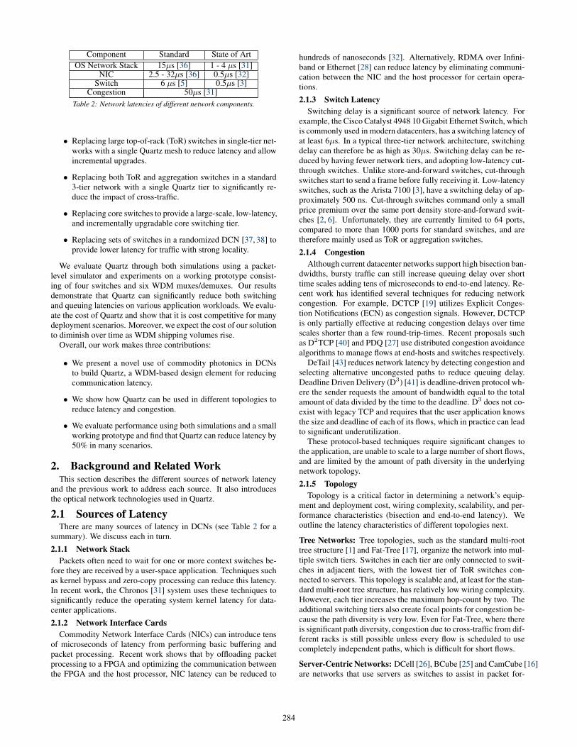
Figure 3: Quartz switches with n = 8 and k = 6. Each switch is onlyphysically connected to two nearby switches by an optical cable. Switch 1and switch 2 are connected using channel λ12. Switch 1 and switch 3 areconnected using wavelength channel λ13.
warding. These are scalable networks with high bisection band-width and path diversity. However, using servers to perform packetforwarding can introduce substantial delays in the OS network stack.Furthermore, server-centric networks can reduce the performanceof computationally-intensive jobs, because high-bandwidth packetforwarding requires a significant number of CPU cycles [16, 37].
Randomized Networks: SWDC [37] and Jellyfish [38] propose torandomly connect servers or switches in a datacenter network. Ran-dom topologies usually have high path diversity and high bisectionbandwidth. However, the worst case network diameter is typicallymuch larger than a similar size tree network, even if the averagepath length is smaller. Randomized networks are also difficult todeploy and manage as they have very high wiring complexity.
Mesh Networks: Mesh networks directly connect every node toevery other node, where a node can either be a server or a switch.A full mesh network provides the lowest possible network diame-ter and eliminates congestion arising from cross-traffic from othernodes. These properties make mesh networks an attractive optionfor low-latency DCNs. However, mesh topologies are rarely usedin DCNs because the O(n2) connections requirement greatly limitsscalability and increases wiring complexity.
2.2 Optical Network TechnologiesOur work takes advantage of optical multiplexers and demul-
tiplexers (mux/demux) to reduce the wiring complexity of meshnetworks. An optical mux/demux uses Wavelength Division Multi-plexing (WDM) to carry multiple network connections using dif-ferent wavelengths in a single optical cable. Through judiciousselection of wavelengths, it is possible to implement a full meshnetwork as a small set of optical rings that share a single physicalring. Importantly, unlike packet switching approaches, optical mul-tiplexing and demultiplexing does not introduce additional switch-ing or queuing latency.
It is also important to distinguish between a WDM and an op-tical switch. A WDM is a low-cost commodity photonic elementthat is deployed at mass-scale to build fiber-to-the-home networks.Figure 1 (taken from [20]) shows that the cost of DWDMs (DenseWDMs) have fallen at an exponential rate since 1993. Assum-ing this trend continues to hold, Quartz will only become morecost-competitive over time. In contrast, optical switches are com-plex, low-volume, and expensive to build due to the use of customASICs.
3. QuartzQuartz is a WDM-ring network that implements a full mesh as a
single physical ring. We now describe it in more detail.
Rack 6
Rack 1 Rack 2
Rack 3
Rack 4 Rack 5
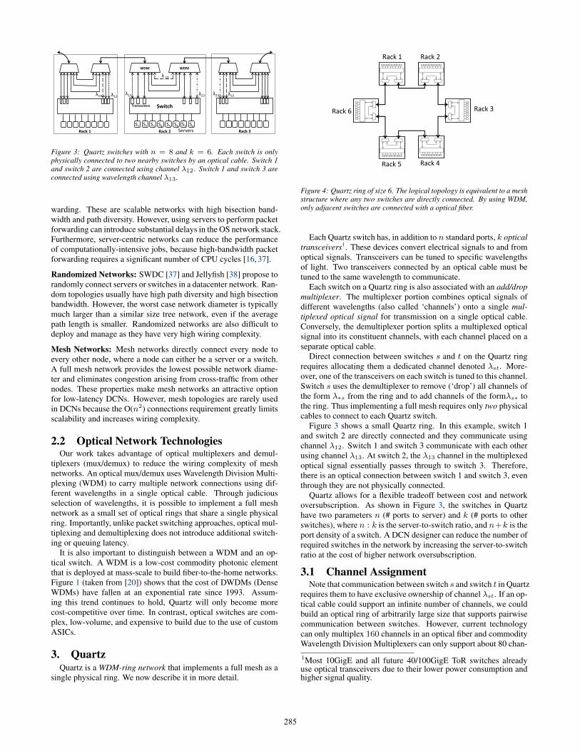
Figure 4: Quartz ring of size 6. The logical topology is equivalent to a meshstructure where any two switches are directly connected. By using WDM,only adjacent switches are connected with a optical fiber.
Each Quartz switch has, in addition to n standard ports, k opticaltransceivers1. These devices convert electrical signals to and fromoptical signals. Transceivers can be tuned to specific wavelengthsof light. Two transceivers connected by an optical cable must betuned to the same wavelength to communicate.
Each switch on a Quartz ring is also associated with an add/dropmultiplexer. The multiplexer portion combines optical signals ofdifferent wavelengths (also called ‘channels’) onto a single mul-tiplexed optical signal for transmission on a single optical cable.Conversely, the demultiplexer portion splits a multiplexed opticalsignal into its constituent channels, with each channel placed on aseparate optical cable.
Direct connection between switches s and t on the Quartz ringrequires allocating them a dedicated channel denoted λst. More-over, one of the transceivers on each switch is tuned to this channel.Switch s uses the demultiplexer to remove (‘drop’) all channels ofthe form λ∗s from the ring and to add channels of the formλs∗ tothe ring. Thus implementing a full mesh requires only two physicalcables to connect to each Quartz switch.
Figure 3 shows a small Quartz ring. In this example, switch 1and switch 2 are directly connected and they communicate usingchannel λ12. Switch 1 and switch 3 communicate with each otherusing channel λ13. At switch 2, the λ13 channel in the multiplexedoptical signal essentially passes through to switch 3. Therefore,there is an optical connection between switch 1 and switch 3, eventhrough they are not physically connected.
Quartz allows for a flexible tradeoff between cost and networkoversubscription. As shown in Figure 3, the switches in Quartzhave two parameters n (# ports to server) and k (# ports to otherswitches), where n : k is the server-to-switch ratio, and n+k is theport density of a switch. A DCN designer can reduce the number ofrequired switches in the network by increasing the server-to-switchratio at the cost of higher network oversubscription.
3.1 Channel AssignmentNote that communication between switch s and switch t in Quartz
requires them to have exclusive ownership of channel λst. If an op-tical cable could support an infinite number of channels, we couldbuild an optical ring of arbitrarily large size that supports pairwisecommunication between switches. However, current technologycan only multiplex 160 channels in an optical fiber and commodityWavelength Division Multiplexers can only support about 80 chan-
1Most 10GigE and all future 40/100GigE ToR switches alreadyuse optical transceivers due to their lower power consumption andhigher signal quality.
285
nels. Therefore, we need to determine the optimal way to assignchannels such that we can build a ring of size K using the mini-mum number of channels.
Quartz attempts to assign Λ available channels to each pair ofswitches in a ring of size M using two principles: (1) For anytwo switches s, t in the ring, there exists an optical path betweenthem using wavelength λst. (2) For all optical links on the path be-tween s and t, there is no other channel using the same wavelengthλst. For example, in Figure 4 if switch 1 and switch 3 are usingwavelength λ13, then using λ13 between rack 2 and rack 4 shouldbe avoided, because λ13 would be used twice on the link betweenswitch 2 and switch 3.
Given these constraints, the wavelength assignment problem canbe formulated as an Integer Linear Program (ILP) similar to [42].The ILP problem is known to be NP-Complete. However, for asmall ring, we can still find the optimal solution by ILP. We alsointroduce a greedy packing algorithm to calculate the minimumnumber of wavelengths needed for building such a ring for largerring sizes. The ILP Formulation and our greedy algorithm are asfollows:
Let Cs,t,i denote the clockwise path from s to t using channeli ∈ {1, ...,Λ} and let Ct,s,i denote the anti-clockwise path. Vari-able Cs,t,i is set to 1 if channel i is used for communication be-tween s and t. Each s, t switch pair should use one channel fortheir communication on either clockwise or counter-clockwise di-rection (Eq. 2).
Variable Ls,t,i,m is the indicator variable of whether link m, thelink between switchm and (m+ 1)modM , is using channel i forthe path between switch s and t. We define static value Ps,t,m = 1if the clockwise path between s and t passes through linkm. If linkm is on the path between switch s and switch t, and wavelength iis used for their communication Ls,t,i,m. This is guaranteed by Eq.3.
On each link m, a single channel i should be only used at mostonce. We ensure this set of constraints by Eq. 4. To count the totalnumber of channels used, variable λi is created to show whetherchannel i is used in the ring. Eq. 5 makes sure that λi equals 1 ifchannel i is used in the ring.
minimize:∑i
λi (1)
subject to:
∀s < t,∑i
Cs,t,i +∑i
Ct,s,i = 1 (2)
∀s, t, i,m, Ls,t,i,m = Ps,t,mCs,t,i (3)
∀m, i,∑s,t
Ls,t,i,m ≤ 1 (4)
∀i,∑
Ls,t,i,m ≤Mλi (5)
∀ variable ∈ {0, 1} (6)
The goal is to minimize the total number of used channels. If theILP is solvable, it means all switch pairs can communicate witheach other. The optimization result is the minimum number ofchannels required for the given ring size.
3.1.1 Greedy Channel AssignmentWe outline a simple, greedy algorithm to solve the channel as-
signment problem. For all the paths between switch pairs (s, t),they are first sorted by their length. For a ring with M nodes, themaximum path length between two switches is bM/2c, so there arebM/2c sets of path lengths. Consider an algorithm with bM/2c it-
0
50
100
150
200
250
300
1 6 11 16 21 26 31 36 41
Wav
elen
gth
req
uir
ed
Ring Size
Greedy Approximation
Optimal by ILP
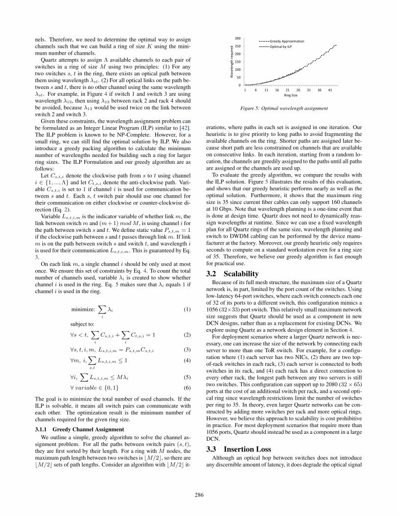
Figure 5: Optimal wavelength assignment
erations, where paths in each set is assigned in one iteration. Ourheuristic is to give priority to long paths to avoid fragmenting theavailable channels on the ring. Shorter paths are assigned later be-cause short path are less constrained on channels that are availableon consecutive links. In each iteration, starting from a random lo-cation, the channels are greedily assigned to the paths until all pathsare assigned or the channels are used up.
To evaluate the greedy algorithm, we compare the results withthe ILP solution. Figure 5 illustrates the results of this evaluation,and shows that our greedy heuristic performs nearly as well as theoptimal solution. Furthermore, it shows that the maximum ringsize is 35 since current fiber cables can only support 160 channelsat 10 Gbps. Note that wavelength planning is a one-time event thatis done at design time. Quartz does not need to dynamically reas-sign wavelengths at runtime. Since we can use a fixed wavelengthplan for all Quartz rings of the same size, wavelength planning andswitch to DWDM cabling can be performed by the device manu-facturer at the factory. Moreover, our greedy heuristic only requiresseconds to compute on a standard workstation even for a ring sizeof 35. Therefore, we believe our greedy algorithm is fast enoughfor practical use.
3.2 ScalabilityBecause of its full mesh structure, the maximum size of a Quartz
network is, in part, limited by the port count of the switches. Usinglow-latency 64-port switches, where each switch connects each oneof 32 of its ports to a different switch, this configuration mimics a1056 (32×33) port switch. This relatively small maximum networksize suggests that Quartz should be used as a component in newDCN designs, rather than as a replacement for existing DCNs. Weexplore using Quartz as a network design element in Section 4.
For deployment scenarios where a larger Quartz network is nec-essary, one can increase the size of the network by connecting eachserver to more than one ToR switch. For example, for a configu-ration where (1) each server has two NICs, (2) there are two top-of-rack switches in each rack, (3) each server is connected to bothswitches in its rack, and (4) each rack has a direct connection toevery other rack, the longest path between any two servers is stilltwo switches. This configuration can support up to 2080 (32× 65)ports at the cost of an additional switch per rack, and a second opti-cal ring since wavelength restrictions limit the number of switchesper ring to 35. In theory, even larger Quartz networks can be con-structed by adding more switches per rack and more optical rings.However, we believe this approach to scalability is cost prohibitivein practice. For most deployment scenarios that require more than1056 ports, Quartz should instead be used as a component in a largeDCN.
3.3 Insertion LossAlthough an optical hop between switches does not introduce
any discernible amount of latency, it does degrade the optical signal
286
due to insertion loss from the WDMs. Quartz compensates for thissignal degradation by adding pump laser-based signal amplifiers asneeded between optical hops.
To determine the feasibility of this approach, we evaluate thecost of adding signal amplifiers in a 24-node Quartz ring. In thisexample, we use 10Gbps DWDM transceivers [7], and 80 channelDWDMs [8]. The transceiver has a maximum output power of 4dBm and a receiver sensitivity of -15 dBm. A typical 80 channelDWDM has an insertion loss of 6 dB. Therefore, the number ofDWDMs that a channel can pass through without amplification is:
(4dBm− (−15dBm))/6dB = 3.17
In this configuration, we need to add a signal amplifier [12] af-ter every sequence of three DWDMs. Since each optical hop inthe ring requires traversing two DWDMs, we need one amplifierfor every two switches. This only increases the cost of a 24-nodeQuartz ring by three percent. To avoid overloading the amplifiersand transceivers, we also need to add optical attenuators to the ring.However, attenuators [10] are simple passive devices that do notmeaningfully affect the cost of the network.
3.4 Routing in QuartzWe now discuss the integration of Quartz into link layer address-
ing and routing. A naïve approach to routing in Quartz would beto treat all servers as being in the same L2 Ethernet network. How-ever, because Ethernet creates a single spanning tree to determinethe forwarding path of packets, it can only utilize a small frac-tion of the links in the network. To utilize all direct paths betweenswitches, we advocate using ECMP routing in the Quartz’s mesh.Since there is a single shortest path between any pair of switches ina full mesh, ECMP always selects the direct one-hop path, whichminimizes hop count and interference from cross-traffic.
A possible problem with only using the direct paths in Quartzis the amount of bandwidth oversubscription between each pair ofswitches. In a Quartz configuration using 64-port switches where32 ports from each switch are connected to servers, there is a 32:1oversubscription between racks, which can be a problem for certainworkloads. However, workloads that spread traffic across differ-ent racks, such as standard scatter/gather workloads in large-scalecomputational platforms such as MPI [24] and MapReduce [21],are unaffected by this kind of independent, rack-to-rack bandwidthoversubscription.
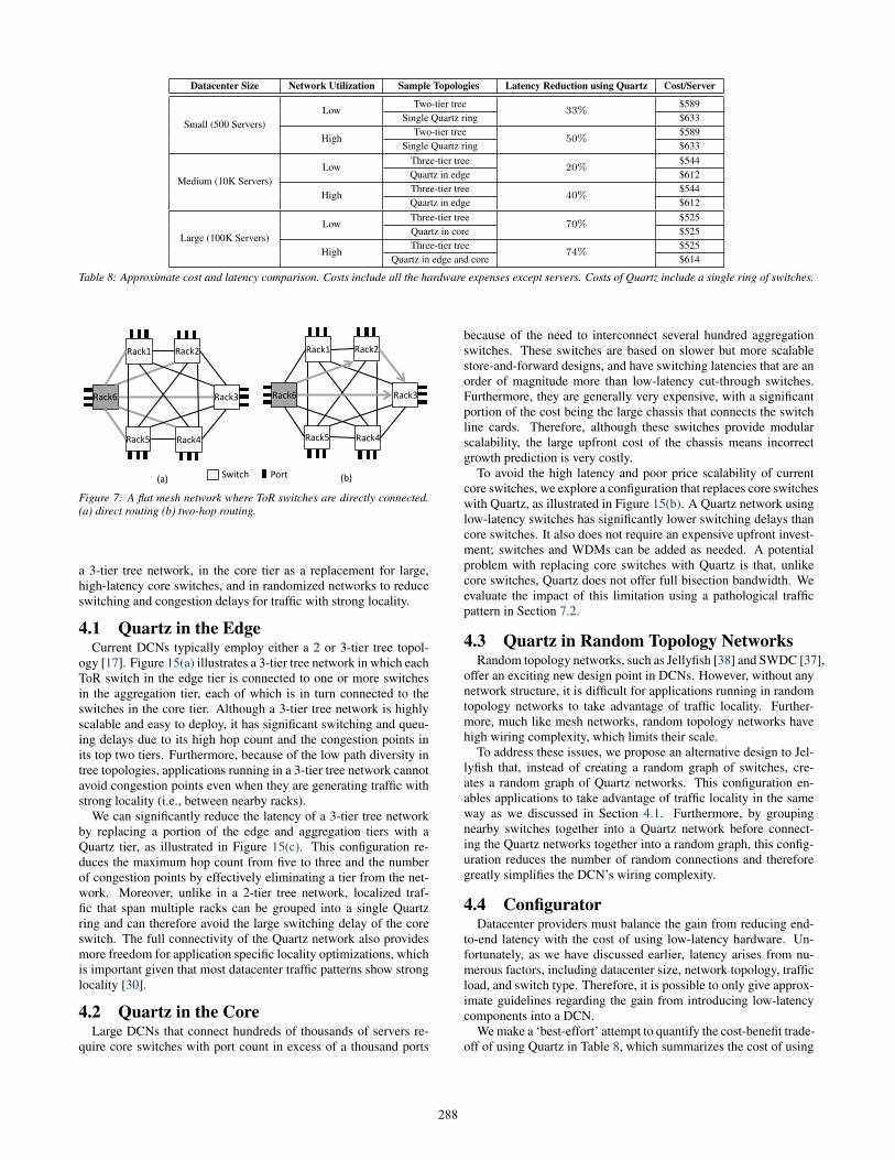
For workloads that concentrate traffic between two racks, onecan significantly reduce rack-to-rack oversubscription by using Val-iant Load Balancing (VLB) [22,33] to make use of two-hop routes.We configure each switch to send k fraction of the traffic throughthe n − 2 two-hop paths and the remaining fraction through thedirect path. For instance, if there is a large amount of traffic fromrack 6 to rack 3 in Figure 7(b), VLB will send k fraction of thistraffic through Rack 1, 2, 4, and 5 over two-hop paths. The param-eter k can be adaptive depending on the traffic characteristics. Weprovide a detailed bandwidth analysis of Quartz and different treetopologies in Section 5.1. Quartz not only reduces transmissiondelay, it also reduces queuing delay by reducing congestion due tocross-traffic. We evaluate the impact of cross-traffic on latency inSection 6.1.
3.5 Fault ToleranceRings are well known to be less fault tolerant than a multi-rooted
tree: two link failures in a ring partition the network. However,by using multiple physical optical fibers to interconnect switchesand multi-hop paths, we can significantly reduce the likelihood ofpartitioning the network. For example, if a Quartz network with 33
0
0.2
0.4
0.6
0.8
1
1 2 3 4Pre
cen
tage
of
Ban
dw
idth
Lo
ss
Number of Rings
1 2 3 4Number of Broken Fiber Links
0
0.1
0.2
0.3
0.4
0.5
0.6
0.7
0.8
0.9
1
1 2 3 4
Pro
bab
ility
of
Part
itio
n
Number of Rings
1 2 3 4
Number of Broken Fiber Links
0 0 0 0 0 0 0 0 0 0 0 0
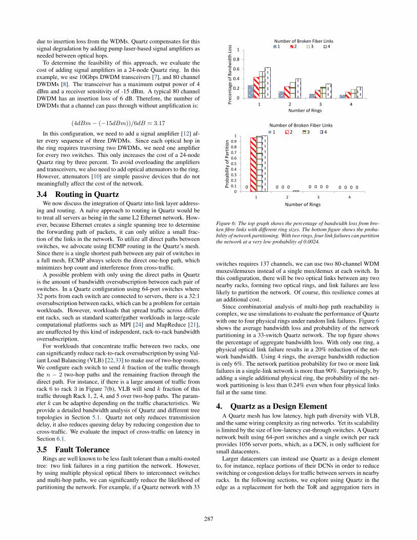
Figure 6: The top graph shows the percentage of bandwidth loss from bro-ken fibre links with different ring sizes. The bottom figure shows the proba-bility of network partitioning. With two rings, four link failures can partitionthe network at a very low probability of 0.0024.
switches requires 137 channels, we can use two 80-channel WDMmuxes/demuxes instead of a single mux/demux at each switch. Inthis configuration, there will be two optical links between any twonearby racks, forming two optical rings, and link failures are lesslikely to partition the network. Of course, this resilience comes atan additional cost.
Since combinatorial analysis of multi-hop path reachability iscomplex, we use simulations to evaluate the performance of Quartzwith one to four physical rings under random link failures. Figure 6shows the average bandwidth loss and probability of the networkpartitioning in a 33-switch Quartz network. The top figure showsthe percentage of aggregate bandwidth loss. With only one ring, aphysical optical link failure results in a 20% reduction of the net-work bandwidth. Using 4 rings, the average bandwidth reductionis only 6%. The network partition probability for two or more linkfailures in a single-link network is more than 90%. Surprisingly, byadding a single additional physical ring, the probability of the net-work partitioning is less than 0.24% even when four physical linksfail at the same time.
4. Quartz as a Design ElementA Quartz mesh has low latency, high path diversity with VLB,
and the same wiring complexity as ring networks. Yet its scalabilityis limited by the size of low-latency cut-through switches. A Quartznetwork built using 64-port switches and a single switch per rackprovides 1056 server ports, which, as a DCN, is only sufficient forsmall datacenters.
Larger datacenters can instead use Quartz as a design elementto, for instance, replace portions of their DCNs in order to reduceswitching or congestion delays for traffic between servers in nearbyracks. In the following sections, we explore using Quartz in theedge as a replacement for both the ToR and aggregation tiers in
287
Datacenter Size Network Utilization Sample Topologies Latency Reduction using Quartz Cost/Server
Small (500 Servers)Low
Two-tier tree33%
$589Single Quartz ring $633
HighTwo-tier tree
50%$589
Single Quartz ring $633
Medium (10K Servers)Low
Three-tier tree20%
$544Quartz in edge $612
HighThree-tier tree
40%$544
Quartz in edge $612
Large (100K Servers)Low
Three-tier tree70%
$525Quartz in core $525
HighThree-tier tree
74%$525
Quartz in edge and core $614
Table 8: Approximate cost and latency comparison. Costs include all the hardware expenses except servers. Costs of Quartz include a single ring of switches.
Rack1 Rack2
Rack6 Rack3
Rack5 Rack4
Port Switch (a) (b)
Rack1 Rack2
Rack6 Rack3
Rack5 Rack4
Figure 7: A flat mesh network where ToR switches are directly connected.(a) direct routing (b) two-hop routing.
a 3-tier tree network, in the core tier as a replacement for large,high-latency core switches, and in randomized networks to reduceswitching and congestion delays for traffic with strong locality.
4.1 Quartz in the EdgeCurrent DCNs typically employ either a 2 or 3-tier tree topol-
ogy [17]. Figure 15(a) illustrates a 3-tier tree network in which eachToR switch in the edge tier is connected to one or more switchesin the aggregation tier, each of which is in turn connected to theswitches in the core tier. Although a 3-tier tree network is highlyscalable and easy to deploy, it has significant switching and queu-ing delays due to its high hop count and the congestion points inits top two tiers. Furthermore, because of the low path diversity intree topologies, applications running in a 3-tier tree network cannotavoid congestion points even when they are generating traffic withstrong locality (i.e., between nearby racks).
We can significantly reduce the latency of a 3-tier tree networkby replacing a portion of the edge and aggregation tiers with aQuartz tier, as illustrated in Figure 15(c). This configuration re-duces the maximum hop count from five to three and the numberof congestion points by effectively eliminating a tier from the net-work. Moreover, unlike in a 2-tier tree network, localized traf-fic that span multiple racks can be grouped into a single Quartzring and can therefore avoid the large switching delay of the coreswitch. The full connectivity of the Quartz network also providesmore freedom for application specific locality optimizations, whichis important given that most datacenter traffic patterns show stronglocality [30].
4.2 Quartz in the CoreLarge DCNs that connect hundreds of thousands of servers re-
quire core switches with port count in excess of a thousand ports
because of the need to interconnect several hundred aggregationswitches. These switches are based on slower but more scalablestore-and-forward designs, and have switching latencies that are anorder of magnitude more than low-latency cut-through switches.Furthermore, they are generally very expensive, with a significantportion of the cost being the large chassis that connects the switchline cards. Therefore, although these switches provide modularscalability, the large upfront cost of the chassis means incorrectgrowth prediction is very costly.
To avoid the high latency and poor price scalability of currentcore switches, we explore a configuration that replaces core switcheswith Quartz, as illustrated in Figure 15(b). A Quartz network usinglow-latency switches has significantly lower switching delays thancore switches. It also does not require an expensive upfront invest-ment; switches and WDMs can be added as needed. A potentialproblem with replacing core switches with Quartz is that, unlikecore switches, Quartz does not offer full bisection bandwidth. Weevaluate the impact of this limitation using a pathological trafficpattern in Section 7.2.
4.3 Quartz in Random Topology NetworksRandom topology networks, such as Jellyfish [38] and SWDC [37],
offer an exciting new design point in DCNs. However, without anynetwork structure, it is difficult for applications running in randomtopology networks to take advantage of traffic locality. Further-more, much like mesh networks, random topology networks havehigh wiring complexity, which limits their scale.
To address these issues, we propose an alternative design to Jel-lyfish that, instead of creating a random graph of switches, cre-ates a random graph of Quartz networks. This configuration en-ables applications to take advantage of traffic locality in the sameway as we discussed in Section 4.1. Furthermore, by groupingnearby switches together into a Quartz network before connect-ing the Quartz networks together into a random graph, this config-uration reduces the number of random connections and thereforegreatly simplifies the DCN’s wiring complexity.
4.4 ConfiguratorDatacenter providers must balance the gain from reducing end-
to-end latency with the cost of using low-latency hardware. Un-fortunately, as we have discussed earlier, latency arises from nu-merous factors, including datacenter size, network topology, trafficload, and switch type. Therefore, it is possible to only give approx-imate guidelines regarding the gain from introducing low-latencycomponents into a DCN.
We make a ‘best-effort’ attempt to quantify the cost-benefit trade-off of using Quartz in Table 8, which summarizes the cost of using
288
Quartz in various network configurations. We consider differentdatacenter sizes, ranging from 500 servers to 100,000 servers. Forall of the tree-based configurations, we use cut-through switches [4]in the edge and aggregation tiers, and high-port density store-and-forward switches [9] in the core tier. We also use commerciallyavailable amplifiers [12], DWDMs [8], and transceivers [7]. Tosimplify the evaluation, the prices include all the hardware ex-penses except for the cost of the servers.
We take into account (at a very high level) the network utiliza-tion of a datacenter; we consider when the network’s utilizationis ‘high,’ which corresponds to a mean link utilization of 70%,and ‘low,’ which corresponds to a mean link utilization of 50%.We also investigate various network topologies including a two-tier tree, three-tier tree, a single Quartz ring, and the use of Quartzin the edge or core layer (or both). We present the approximatepacket latency reduction from using Quartz based on our simula-tion results in Section 7 and the cost per server for these variousnetwork configurations.
We first analyse the use of Quartz for small datacenters, whichhave approximately 500 servers. We observe that the use of Quartzincreases the cost per server by 7% compared to a two-tier treestructure. However, we can achieve a latency reduction of at least33% in an environment with low network utilization and more than50% with high network utilization.
In the case for medium-sized datacenters, which consists of 10,000servers, we find that the use of Quartz increases the cost of the dat-acenter by 13% and reduces the datacenter’s latency by 20% withlow traffic, and more than 40% with high traffic. The cost of usingQuartz is higher in a medium-sized datacenter than a small-sizeddatacenter because of the larger size of the Quartz ring needed toserve more servers; thus, more optical hardware is required.
Finally, we consider a large datacenter that contains 100,000servers. We find that using Quartz at the core layer does not in-crease cost per server since the three-tier tree requires a high portdensity switch. As high port density switches are also expensive,their cost is similar to the optical hardware that is found in a Quartzring. By replacing high port density switches with Quartz rings,we see a 70% improvement in latency with low traffic. We alsoconsider the use of Quartz at the both edge and core layer in anenvironment with high network utilization. We see that the costincreases by 17% and latency is reduced by more than 74%.
To summarize, we realize that it is impossible to give exact cost-benefit tradeoffs due to the numerous sources of network latency.We demonstrate however that (a) Quartz can be used as a designelement in many different standard DCNs (b) the additional (one-time) cost due to introducing Quartz is fairly small and (c) in allcases, using Quartz significantly reduces end-to-end latency.
5. AnalysisWe analyze the properties of five representative network topolo-
gies (2-tier tree, Fat-Tree [17], BCube [25], Jellyfish [38] and mesh)and determine their suitability as a low-latency network design el-ement. In this analysis, we configure each topology to mimic asingle switch with approximately 1000 ports. We compute the pathdiversity of each topology using the metric defined in [39]. Notethat Jellyfish’s path diversity depends on both the chosen routingalgorithm (k-shortest-path or ECMP) and the number of switch-to-switch links. We define wiring complexity as the number of cross-rack links. Table 9 shows a summary of their key properties.
Out of the five network topologies, the 2-tier tree structure re-quires the fewest switches to provide 1k usable ports and thereforehas the lowest relative equipment cost. It is also the simplest struc-ture to wire; each ToR switch only has a small constant number of
0
0.2
0.4
0.6
0.8
1
Random Permutation Incast Rack Level Shuffle
No
rmal
ized
Th
rou
ghp
ut
Full Bisection Bandwidth Quartz
1/2 Bisection Bandwidth 1/4 Bisection Bandwidth
Figure 10: Normalized throughput for three different traffic patterns
connections to each of the second tier switches. However, as estab-lished by previous work [17], providing high bisection bandwidthin a tree network requires high port count second tier switches thatare both expensive and, more importantly, have high latency. Thisproblem, combined with its low path diversity, which can resultin significant congestive delays, make 2-tier tree networks a poorchoice for a low-latency design element.
By increasing path diversity, Fat-Tree, BCube, and Jellyfish havelower congestive delays and offer significantly more bisection band-width than 2-tier tree networks without requiring high port countswitches. Fat-tree is the most expensive of the three structures,but provides full bisection bandwidth without requiring server-sidepacket switching. BCube’s use of server-side packet switching re-sults in the highest latency of the five topologies. All three systemshave relatively high wiring complexity.
Finally, a mesh network offers the highest path diversity, lowesthop count and latency when using direct routing, and relatively highbisection bandwidth when using indirect routing with VLB. It alsohas relatively high wiring complexity, but by implementing it usinga WDM ring, the wiring complexity can be simplified to be as lowas a 2-tier tree network.
5.1 Bisection BandwidthGiven Quartz’s high path diversity, it is difficult to analytically
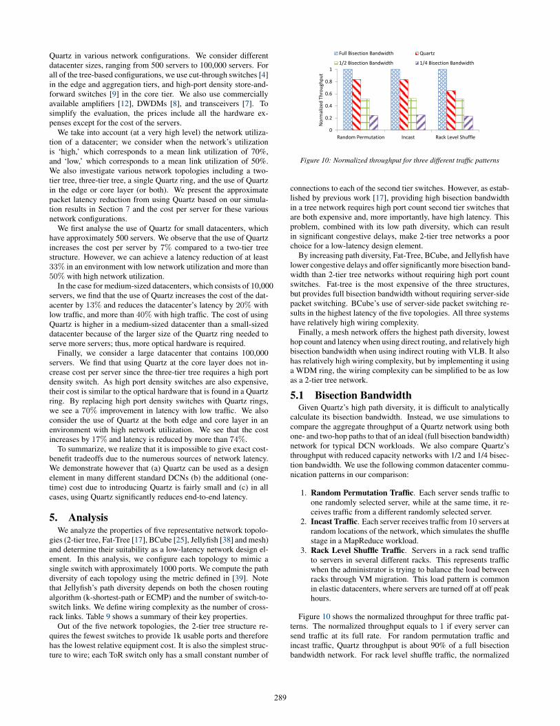
calculate its bisection bandwidth. Instead, we use simulations tocompare the aggregate throughput of a Quartz network using bothone- and two-hop paths to that of an ideal (full bisection bandwidth)network for typical DCN workloads. We also compare Quartz’sthroughput with reduced capacity networks with 1/2 and 1/4 bisec-tion bandwidth. We use the following common datacenter commu-nication patterns in our comparison:
1. Random Permutation Traffic. Each server sends traffic toone randomly selected server, while at the same time, it re-ceives traffic from a different randomly selected server.
2. Incast Traffic. Each server receives traffic from 10 servers atrandom locations of the network, which simulates the shufflestage in a MapReduce workload.
3. Rack Level Shuffle Traffic. Servers in a rack send trafficto servers in several different racks. This represents trafficwhen the administrator is trying to balance the load betweenracks through VM migration. This load pattern is commonin elastic datacenters, where servers are turned off at off peakhours.
Figure 10 shows the normalized throughput for three traffic pat-terns. The normalized throughput equals to 1 if every server cansend traffic at its full rate. For random permutation traffic andincast traffic, Quartz throughput is about 90% of a full bisectionbandwidth network. For rack level shuffle traffic, the normalized
289
Network Latency without Congestion # of 64-port Switches Wiring Complexity Path Diversity2-Tier Tree 1.5µs (3 Switch Hops) 17 16 1
Fat-Tree 1.5µs (3 Switch Hops) 48 1024 32BCube 16µs (2 Switch Hops & 1 Server Hop) 32 960 2
Jellyfish 1.5µs (3 Switch Hops) 24 240 ≤32
Mesh 1.0µs (2 Switch Hops) 33 528 3232 (with WDMs)Table 9: Summary of different network structures with 1k servers
Figure 11: Quartz with 4 switches, connected by WDMs
throughput is about 0.75. We conclude that Quartz’s bisection band-width is less than full bisection bandwidth but greater than 1/2 bi-section bandwidth. Overall, Quartz provides significantly higherthroughput than the other oversubscribed network topologies forall three traffic patterns.
6. PrototypeIn this section, we validate the Quartz design by building a small
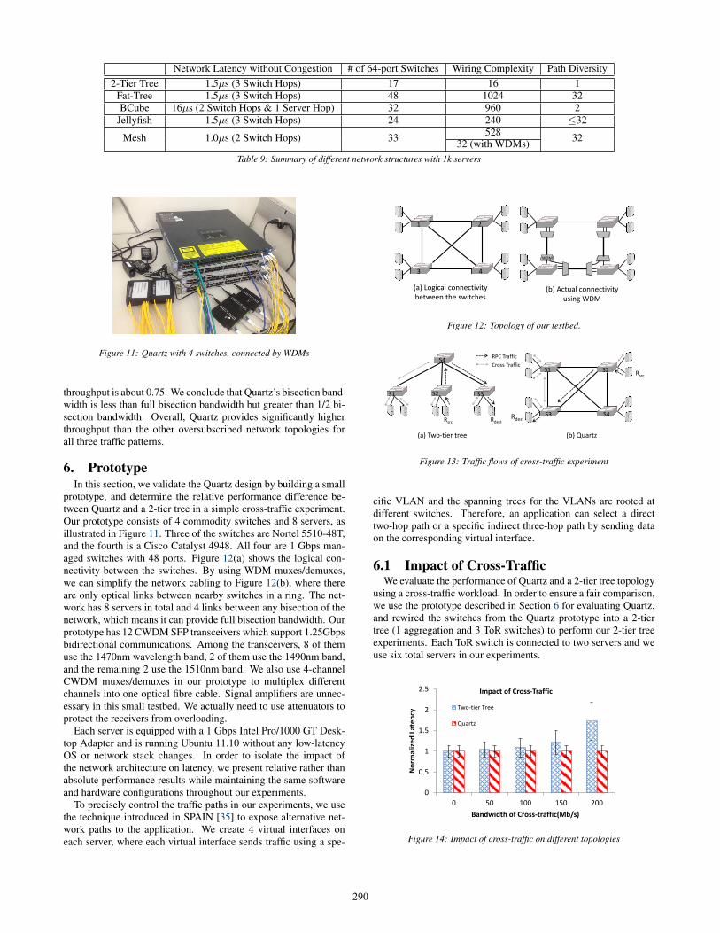
prototype, and determine the relative performance difference be-tween Quartz and a 2-tier tree in a simple cross-traffic experiment.Our prototype consists of 4 commodity switches and 8 servers, asillustrated in Figure 11. Three of the switches are Nortel 5510-48T,and the fourth is a Cisco Catalyst 4948. All four are 1 Gbps man-aged switches with 48 ports. Figure 12(a) shows the logical con-nectivity between the switches. By using WDM muxes/demuxes,we can simplify the network cabling to Figure 12(b), where thereare only optical links between nearby switches in a ring. The net-work has 8 servers in total and 4 links between any bisection of thenetwork, which means it can provide full bisection bandwidth. Ourprototype has 12 CWDM SFP transceivers which support 1.25Gbpsbidirectional communications. Among the transceivers, 8 of themuse the 1470nm wavelength band, 2 of them use the 1490nm band,and the remaining 2 use the 1510nm band. We also use 4-channelCWDM muxes/demuxes in our prototype to multiplex differentchannels into one optical fibre cable. Signal amplifiers are unnec-essary in this small testbed. We actually need to use attenuators toprotect the receivers from overloading.
Each server is equipped with a 1 Gbps Intel Pro/1000 GT Desk-top Adapter and is running Ubuntu 11.10 without any low-latencyOS or network stack changes. In order to isolate the impact ofthe network architecture on latency, we present relative rather thanabsolute performance results while maintaining the same softwareand hardware configurations throughout our experiments.
To precisely control the traffic paths in our experiments, we usethe technique introduced in SPAIN [35] to expose alternative net-work paths to the application. We create 4 virtual interfaces oneach server, where each virtual interface sends traffic using a spe-
(a) Logical connectivity between the switches
WDM
(b) Actual connectivity using WDM
1 2
3 4
Figure 12: Topology of our testbed.
(b) Quartz
S1 S2
S3 S4
S1 S3
(a) Two-tier tree
S2
Rsrc Rdest
Rsrc
S4
Rdest
RPC Traffic
Cross Traffic
Figure 13: Traffic flows of cross-traffic experiment
cific VLAN and the spanning trees for the VLANs are rooted atdifferent switches. Therefore, an application can select a directtwo-hop path or a specific indirect three-hop path by sending dataon the corresponding virtual interface.
6.1 Impact of Cross-TrafficWe evaluate the performance of Quartz and a 2-tier tree topology
using a cross-traffic workload. In order to ensure a fair comparison,we use the prototype described in Section 6 for evaluating Quartz,and rewired the switches from the Quartz prototype into a 2-tiertree (1 aggregation and 3 ToR switches) to perform our 2-tier treeexperiments. Each ToR switch is connected to two servers and weuse six total servers in our experiments.
0
0.5
1
1.5
2
2.5
0 50 100 150 200
No
rmal
ize
d L
ate
ncy
Bandwidth of Cross-traffic(Mb/s)
Impact of Cross-Traffic
Two-tier Tree
Quartz
Figure 14: Impact of cross-traffic on different topologies
290
Core
Aggregate
ToR
(a) Three-tier tree
Quartz Core
Aggregate
ToR
(b) Quartz in core
Core
Quartz Ring
(c) Quartz in edge
Quartz Ring
Quartz Core
(d) Quartz in edge and core
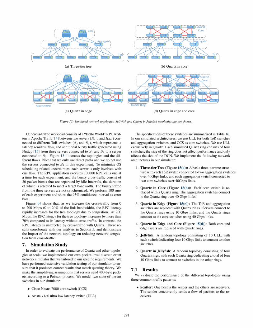
Figure 15: Simulated network topologies. Jellyfish and Quartz in Jellyfish topologies are not shown..
Our cross-traffic workload consists of a “Hello World” RPC writ-ten in Apache Thrift [14] between two servers (Rsrc andRdst) con-nected to different ToR switches (S2 and S3), which represents alatency sensitive flow, and additional bursty traffic generated usingNuttcp [15] from three servers connected to S1 and S2 to a serverconnected to S3. Figure 13 illustrates the topologies and the dif-ferent flows. Note that we only use direct paths and we do not usethe servers connected to S4 in this experiment. To minimize OSscheduling related uncertainties, each server is only involved withone flow. The RPC application executes 10, 000 RPC calls one ata time for each experiment, and the bursty cross-traffic consist of20 packet bursts that are separated by idle intervals, the durationof which is selected to meet a target bandwidth. The bursty trafficfrom the three servers are not synchronized. We perform 100 runsof each experiment and show the 95% confidence interval as errorbars.
Figure 14 shows that, as we increase the cross-traffic from 0to 200 Mbps (0 to 20% of the link bandwidth), the RPC latencyrapidly increases for the tree topology due to congestion. At 200Mbps, the RPC latency for the tree topology increases by more than70% compared to its latency without cross-traffic. In contrast, theRPC latency is unaffected by cross-traffic with Quartz. These re-sults corroborate with our analysis in Section 5, and demonstratethe impact of the network topology on reducing network conges-tion from cross-traffic.
7. Simulation StudyIn order to evaluate the performance of Quartz and other topolo-
gies at scale, we implemented our own packet-level discrete eventnetwork simulator that we tailored to our specific requirements. Wehave performed extensive validation testing of our simulator to en-sure that it produces correct results that match queuing theory. Wemake the simplifying assumptions that servers send 400-byte pack-ets according to a Poisson process. We model two state-of-the-artswitches in our simulator:
• Cisco Nexus 7000 core switch (CCS)
• Arista 7150 ultra low latency switch (ULL)
The specifications of these switches are summarized in Table 16.In our simulated architectures, we use ULL for both ToR switchesand aggregation switches, and CCS as core switches. We use ULLexclusively in Quartz. Each simulated Quartz ring consists of fourswitches; the size of the ring does not affect performance and onlyaffects the size of the DCN. We implement the following networkarchitectures in our simulator:
1. Three-tier Tree (Figure 15(a)): A basic three-tier tree struc-ture with each ToR switch connected to two aggregation switchesover 40Gbps links, and each aggregation switch connected totwo core switches over 40Gbps links.
2. Quartz in Core (Figure 15(b)): Each core switch is re-placed with a Quartz ring. The aggregation switches connectto the Quartz ring over 40 Gbps links.
3. Quartz in Edge (Figure 15(c)): The ToR and aggregationswitches are replaced with Quartz rings. Servers connect tothe Quartz rings using 10 Gbps links, and the Quartz ringsconnect to the core switches using 40 Gbps links.
4. Quartz in Edge and Core (Figure 15(d)): Both core andedge layers are replaced with Quartz rings.
5. Jellyfish: A random topology consisting of 16 ULL, witheach switch dedicating four 10 Gbps links to connect to otherswitches.
6. Quartz in Jellyfish: A random topology consisting of fourQuartz rings, with each Quartz ring dedicating a total of four10 Gbps links to connect to switches in the other rings.
7.1 ResultsWe evaluate the performance of the different topologies using
three common traffic patterns:
• Scatter: One host is the sender and the others are receivers.The sender concurrently sends a flow of packets to the re-ceivers.
291
Switch Latency Port CountCisco Nexus 7000 (CCS) 6 us 768 10Gbps or
192 40GbpsArista 7150S-64 (ULL) 380 ns 64 10Gbps or
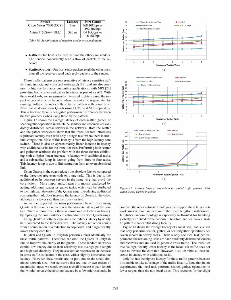
16 40GbpsTable 16: Specifications of switches used in our simulations.
• Gather: One host is the receiver and the others are senders.The senders concurrently send a flow of packets to the re-ceiver.
• Scatter/Gather: One host sends packets to all the other hosts,then all the receivers send back reply packets to the sender.
These traffic patterns are representative of latency sensitive traf-fic found in social networks and web search [19], and are also com-mon in high-performance computing applications, with MPI [24]providing both scatter and gather functions as part of its API. Withthese workloads, we are primarily interested in determining the im-pact of cross-traffic on latency, where cross-traffic is generated byrunning multiple instances of these traffic patterns at the same time.Note that we do not show Quartz using ECMP and VLB separately.This is because there is negligible performance difference betweenthe two protocols when using these traffic patterns.
Figure 17 shows the average latency of each scatter, gather, orscatter/gather operation in which the senders and receivers are ran-domly distributed across servers in the network. Both the scatterand the gather workloads show that the three-tier tree introducessignificant latency even with only a single task where there is min-imal congestion. Most of this latency is from the high-latency coreswitch. There is also an approximately linear increase in latencywith additional tasks for the three-tier tree. Performing both scatterand gather exacerbates the problem with the three-tier tree exhibit-ing both a higher linear increase in latency with additional tasks,and a substantial jump in latency going from three to four tasks.This latency jump is due to link saturation from an oversubscribedlink.
Using Quartz in the edge reduces the absolute latency comparedto the three-tier tree even with only one task. This is due to theadditional paths between servers in the same ring that avoid thecore switch. More importantly, latency is mostly unaffected byadding additional scatter or gather tasks, which can be attributedto the high path diversity of the Quartz ring. Introducing additionalscatter/gather task does increase the latency of Quartz in the edge,although at a lower rate than the three-tier tree.
As we had expected, the main performance benefit from usingQuartz in the core is a reduction in the absolute latency of the coretier. There is more than a three microsecond reduction in latencyby replacing the core switches in a three-tier tree with Quartz rings.
Using Quartz in both the edge and core reduces latency by nearlyhalf compared to the three-tier tree. The latency reduction comesfrom a combination of a reduction in hop-count, and a significantlylower latency core tier.
Jellyfish and Quartz in Jellyfish perform almost identically forthese traffic patterns. Therefore, we omit the Quartz in Jellyfishline to improve the clarity of the graphs. These random networksexhibit low latency due to their relatively low average path lengthand high path diversity. They have a similar response to an increasein cross-traffic as Quartz in the core, with a slightly lower absolutelatency. However, these results are, in part, due to the small sim-ulated network size. For networks that are one or two orders ofmagnitude larger, we would expect a small increase in path lengththat would increase the absolute latency by a few microseconds. In
0
2
4
6
8
10
12
14
16
18
20
1 2 3 4 5 6 7 8
Late
ncy
pe
r P
acke
t (u
s)
Number of Scatter Tasks
Three-tier Multi-root Tree Jellyfish
Quartz in Core Quartz in Edge
Quartz in Edge and Core
(a)
0
2
4
6
8
10
12
14
16
18
20
1 2 3 4 5 6 7 8
Late
ncy
pe
r P
acke
t (u
s)
Number of Gather Tasks
Three-tier Multi-root Tree Jellyfish
Quartz in Edge Quartz in Core
Quartz in Edge and Core
(b)
0
20
40
60
80
100
120
140
160
180
1 2 3 4
Late
ncy
pe
r P
acke
t (u
s)
Number of Scatter/gather Tasks
Three-tier Multi-root Tree Jellyfish
Quartz in Edge Quartz in Core
Quartz in Edge and Core
(c)
Figure 17: Average latency comparison for global traffic pattern. Thisgraph is best viewed in colour.
contrast, the other network topologies can support these larger net-work sizes without an increase to their path lengths. Furthermore,Jellyfish’s random topology is especially well-suited for handlingglobally distributed traffic patterns. Therefore, we next look at traf-fic patterns that exhibit strong locality.
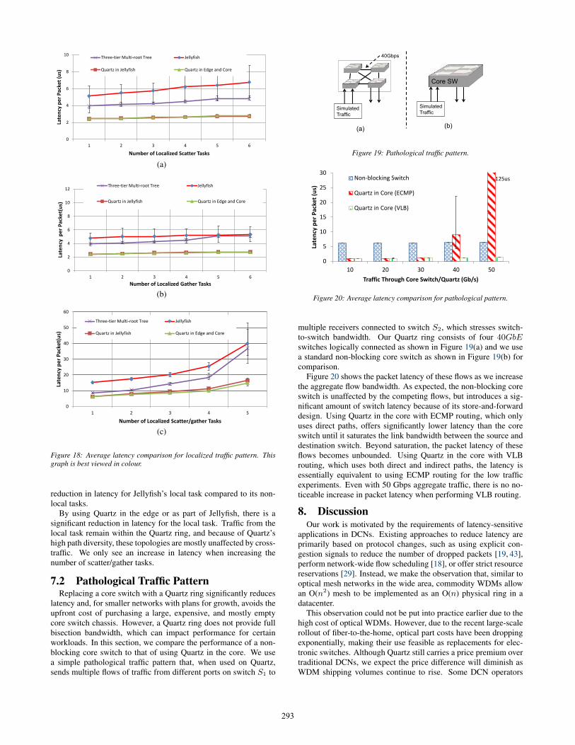
Figure 18 shows the average latency of a local task, that is, a taskthat only performs scatter, gather, or scatter/gather operations be-tween servers in nearby racks. There is only one local task per ex-periment; the remaining tasks are have randomly distributed sendersand receivers and are used to generate cross-traffic. The three-tiertree has significantly lower latency as the local task traffic does nothave to traverse the core tier. However, it still exhibits a linear in-crease in latency with additional tasks.
Jellyfish has the highest latency for these traffic patterns becauseit is unable to take advantage of the traffic locality. Note that in ourexperiments, the local task performs scatter, gather, operations tofewer targets than the non-local tasks. This accounts for the slight
292
0
2
4
6
8
10
1 2 3 4 5 6
Late
ncy
pe
r P
acke
t (u
s)
Number of Localized Scatter Tasks
Three-tier Multi-root Tree Jellyfish
Quartz in Jellyfish Quartz in Edge and Core
(a)
0
2
4
6
8
10
12
1 2 3 4 5 6
Late
ncy
pe
r P
acke
t(u
s)
Number of Localized Gather Tasks
Three-tier Multi-root Tree Jellyfish
Quartz in Jellyfish Quartz in Edge and Core
(b)
0
10
20
30
40
50
60
1 2 3 4 5
Late
ncy
pe
r P
acke
t(u
s)
Number of Localized Scatter/gather Tasks
Three-tier Multi-root Tree Jellyfish
Quartz in Jellyfish Quartz in Edge and Core
(c)
Figure 18: Average latency comparison for localized traffic pattern. Thisgraph is best viewed in colour.
reduction in latency for Jellyfish’s local task compared to its non-local tasks.
By using Quartz in the edge or as part of Jellyfish, there is asignificant reduction in latency for the local task. Traffic from thelocal task remain within the Quartz ring, and because of Quartz’shigh path diversity, these topologies are mostly unaffected by cross-traffic. We only see an increase in latency when increasing thenumber of scatter/gather tasks.
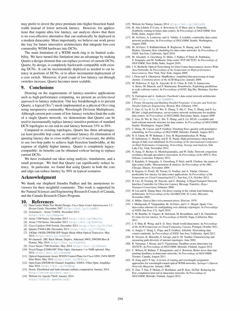
7.2 Pathological Traffic PatternReplacing a core switch with a Quartz ring significantly reduces
latency and, for smaller networks with plans for growth, avoids theupfront cost of purchasing a large, expensive, and mostly emptycore switch chassis. However, a Quartz ring does not provide fullbisection bandwidth, which can impact performance for certainworkloads. In this section, we compare the performance of a non-blocking core switch to that of using Quartz in the core. We usea simple pathological traffic pattern that, when used on Quartz,sends multiple flows of traffic from different ports on switch S1 to
40Gbps
Simulated
Traffic
Core SW
Simulated
Traffic
(a) (b)
Figure 19: Pathological traffic pattern.
0
5
10
15
20
25
30
10 20 30 40 50
Late
ncy
pe
r P
acke
t (u
s)
Traffic Through Core Switch/Quartz (Gb/s)
Non-blocking Switch
Quartz in Core (ECMP)
Quartz in Core (VLB)
125us
Figure 20: Average latency comparison for pathological pattern.
multiple receivers connected to switch S2, which stresses switch-to-switch bandwidth. Our Quartz ring consists of four 40GbEswitches logically connected as shown in Figure 19(a) and we usea standard non-blocking core switch as shown in Figure 19(b) forcomparison.
Figure 20 shows the packet latency of these flows as we increasethe aggregate flow bandwidth. As expected, the non-blocking coreswitch is unaffected by the competing flows, but introduces a sig-nificant amount of switch latency because of its store-and-forwarddesign. Using Quartz in the core with ECMP routing, which onlyuses direct paths, offers significantly lower latency than the coreswitch until it saturates the link bandwidth between the source anddestination switch. Beyond saturation, the packet latency of theseflows becomes unbounded. Using Quartz in the core with VLBrouting, which uses both direct and indirect paths, the latency isessentially equivalent to using ECMP routing for the low trafficexperiments. Even with 50 Gbps aggregate traffic, there is no no-ticeable increase in packet latency when performing VLB routing.
8. DiscussionOur work is motivated by the requirements of latency-sensitive
applications in DCNs. Existing approaches to reduce latency areprimarily based on protocol changes, such as using explicit con-gestion signals to reduce the number of dropped packets [19, 43],perform network-wide flow scheduling [18], or offer strict resourcereservations [29]. Instead, we make the observation that, similar tooptical mesh networks in the wide area, commodity WDMs allowan O(n2) mesh to be implemented as an O(n) physical ring in adatacenter.
This observation could not be put into practice earlier due to thehigh cost of optical WDMs. However, due to the recent large-scalerollout of fiber-to-the-home, optical part costs have been droppingexponentially, making their use feasible as replacements for elec-tronic switches. Although Quartz still carries a price premium overtraditional DCNs, we expect the price difference will diminish asWDM shipping volumes continue to rise. Some DCN operators
293
may prefer to invest the price premium into higher bisection band-width instead of lower network latency. However, for applica-tions that require ultra low latency, our analysis shows that thereis no cost-effective alternative that can realistically be deployed ina modern datacenter. More importantly, we believe our work pavesthe way for future innovative architectures that integrate low-costcommodity WDM hardware into DCNs.
The main limitation of a WDM mesh ring is its limited scala-bility. We have turned this limitation into an advantage by makingQuartz a design element that can replace portions of current DCNs.Quartz, by design, is completely backwards compatible with exist-ing DCNs. It can be incrementally deployed as needed to cut la-tency in portions of DCNs, or to allow incremental deployment ofa core switch. Moreover, if port count of low-latency cut-throughswitches increase, Quartz becomes more scalable.
9. ConclusionsDrawing on the requirements of latency-sensitive applications
such as high-performance computing, we present an architecturalapproach to latency reduction. Our key breakthrough is to presentQuartz, a logical O(n2) mesh implemented as a physical O(n) ringusing inexpensive commodity Wavelength Division Multiplexers.Although current port counts of low-latency switches limit the scaleof a single Quartz network, we demonstrate that Quartz can beused to incrementally replace latency-sensitive portions of standardDCN topologies to cut end-to-end latency between 33% to 50%.
Compared to existing topologies, Quartz has three advantages:(a) least possible hop count, so minimal latency (b) elimination ofqueuing latency due to cross traffic and (c) if necessary, the abilityto use two-hop paths to achieve high bisection bandwidths, at theexpense of slightly higher latency. Quartz is completely legacy-compatible: its benefits can be obtained without having to replacecurrent DCNs.
We have evaluated our ideas using analysis, simulations, and asmall prototype. We find that Quartz can significantly reduce la-tency. In particular, we found that using Quartz in both the coreand edge can reduce latency by 50% in typical scenarios.
AcknowledgmentWe thank our shepherd Jitendra Padhye and the anonymous re-viewers for their insightful comments. This work is supported bythe Natural Sciences and Engineering Research Council of Canada,and the Canada Research Chairs Program.
10. References[1] Data Center Multi-Tier Model Design. Cisco Data Center Infrastructure 2.5
Design Guide, December 2007. http://bit.ly/11usMXi.[2] Acmemicro - Arista 7148SX, December 2013.
http://bit.ly/14xquvm.[3] Arista 7100 Series. December 2013. http://bit.ly/VBo1Ll.[4] Arista 7150 Series. December 2013. http://bit.ly/PUH7uD.[5] Cisco Catalyst 4948 Switch. December 2013. http://bit.ly/VtlIbf.[6] Quanta T3048-LB8, December 2013. http://bit.ly/173tPpz.[7] 10Gbps 10GHz DWDM SFP Single Mode 40km Optical Transceivr, May
2014. http://bit.ly/1hAwCXP.[8] 80 channels, 2RU Rack Mount, Duplex, Athermal AWG, DWDM Mux &
Demux, May 2014. http://bit.ly/1iaUSzG.[9] Cisco Nexus 7700 Switches. May 2014. http://bit.ly/SZGzs2.
[10] Fixed Flange E2000/APC Fiber Optic Attenuator 1 to 30dB optional, May2014. http://bit.ly/1r0skSW.
[11] Optical Impairment-Aware WSON Control Plane for Cisco ONS 15454 MSTPData Sheet, May 2014. http://bit.ly/RC8Ljo.
[12] OpticTrans DWDM 80 Channel Amplifier / EDFA / Fiber Optic Amplifier,June 2014. http://bit.ly/TxiMjg.
[13] Storm: Distributed and fault-tolerant realtime computation, January 2014.http://storm-project.net/.
[14] Website for Apache Thrift, January 2014.http://thrift.apache.org/.
[15] Website for Nuttcp, January 2014. http://bit.ly/1bDluG9.[16] H. Abu-Libdeh, P. Costa, A. Rowstron, G. O’Shea, and A. Donnelly.
Symbiotic routing in future data centers. In Proceedings of SIGCOMM, NewDelhi, India, August 2010.
[17] M. Al-Fares, A. Loukissas, and A. Vahdat. A scalable, commodity data centernetwork architecture. In Proceedings of SIGCOMM, Seattle, Washington,August 2008.
[18] M. Al-Fares, S. Radhakrishnan, B. Raghavan, N. Huang, and A. Vahdat.Hedera: Dynamic flow scheduling for data center networks. In Proceedings ofNSDI, San Jose, California, April 2010.
[19] M. Alizadeh, A. Greenberg, D. Maltz, J. Padhye, P. Patel, B. Prabhakar,S. Sengupta, and M. Sridharan. Data center TCP (DCTCP). In Proceedings ofSIGCOMM, New Delhi, India, August 2010.
[20] J. E. Berthold. Optical Networking for Data Center Interconnects Across WideArea Networks. In Proceedings of the Symposium on High-performanceInterconnects, New York, New York, August 2009.
[21] J. Dean and S. Ghemawat. MapReduce: simplified data processing on largeclusters. Communications of the ACM Magazine, January 2008.
[22] M. Dobrescu, N. Egi, K. Argyraki, B.-G. Chun, K. Fall, G. Iannaccone,A. Knies, M. Manesh, and S. Ratnasamy. Routebricks: Exploiting parallelismto scale software routers. In Proceedings of SOSP, Big Sky, Montana, October2009.
[23] N. Farrington and A. Andreyev. Facebook’s data center network architecture.2013. http://bit.ly/1mABW01.
[24] I. Foster. Designing and Building Parallel Programs: Concepts and Tools forParallel Software Engineering. Boston, MA, Feburary 1995.
[25] C. Guo, G. Lu, D. Li, H. Wu, X. Zhang, Y. Shi, C. Tian, Y. Zhang, and S. Lu.BCube: a high performance, server-centric network architecture for modulardata centers. In Proceedings of SIGCOMM, Barcelona, Spain, August 2009.
[26] C. Guo, H. Wu, K. Tan, L. Shi, Y. Zhang, and S. Lu. DCell: a scalable andfault-tolerant network structure for data centers. In Proceedings of SIGCOMM,Seattle, Washington, August 2008.
[27] C. Hong, M. Caesar, and P. Godfrey. Finishing flows quickly with preemptivescheduling. In Proceedings of SIGCOMM, Helsinki, Finland, August 2012.
[28] N. S. Islam, M. W. Rahman, J. Jose, R. Rajachandrasekar, H. Wang,H. Subramoni, C. Murthy, and D. K. Panda. High performance rdma-baseddesign of hdfs over infiniband. In Proceedings of the International Conferenceon High Performance Computing, Networking, Storage and Analysis, SaltLake City, Utah, November 2012.
[29] N. Jiang, D. Becker, G. Michelogiannakis, and W. Dally. Network congestionavoidance through speculative reservation. In Proceedings of the HPCA, NewOrleans, Louisiana, Feburary 2012.
[30] S. Kandula, S. Sengupta, A. Greenberg, P. Patel, and R. Chaiken. the nature ofdata center traffic: Measurements & analysis. In Proceedings of the IMC,Chicago, Illinois, November 2009.
[31] R. Kapoor, G. Porter, M. Tewari, G. Voelker, and A. Vahdat. Chronos:predictable low latency for data center applications. In Proceedings of theSymposium on Cloud Computing(SoCC), San Jose, CA, October 2012.
[32] H. Litz, H. Froning, M. Nuessle, and U. Bruning. A HyperTransport NetworkInterface Controller for Ultra-low Latency Message Transfers. HyperTransport Consortium, Feburary 2008.
[33] H. Liu and R. Zhang-Shen. On direct routing in the valiant load-balancingarchitecture. In Proceedings of the GLOBECOM, St. Louis, Missouri,November 2005.
[34] S. Miller. Optical fiber telecommunications. Elsevier, 1979.[35] J. Mudigonda, P. Yalagandula, M. Al-Fares, and J. C. Mogul. Spain: Cots
data-center ethernet for multipathing over arbitrary topologies. In Proceedingsof NSDI, San Jose, CA, April 2010.
[36] S. M. Rumble, D. Ongaro, R. Stutsman, M. Rosenblum, and J. K. Ousterhout.It’s time for low latency. In Proceedings of HotOS, Napa, California, May2011.
[37] J.-Y. Shin, B. Wong, and E. G. Sirer. Small-world datacenters. In Proceedingsof the ACM Symposium on Cloud Computing, Cascais, Portugal, October 2011.
[38] A. Singla, C. Hong, L. Popa, and P. Godfrey. Jellyfish: Networking datacenters randomly. In Proceedings of NSDI, San Jose, California, April 2012.
[39] R. Teixeira, K. Marzullo, S. Savage, and G. M. Voelker. Characterizing andmeasuring path diversity of internet topologies. June 2003.
[40] B. Vamanan, J. Hasan, and T. Vijaykumar. Deadline-aware datacenter tcp(D2TCP). In Proceedings of SIGCOMM, Helsinki, Finland, August 2012.
[41] C. Wilson, H. Ballani, T. Karagiannis, and A. Rowtron. Better never than late:meeting deadlines in datacenter networks. In Proceedings of SIGCOMM,Toronto, Canada, August 2011.
[42] H. Zang and J. P. Jue. A review of routing and wavelength assignmentapproaches for wavelength-routed optical WDM networks. Springer’s OpticalNetworks Magazine, January 2000.
[43] D. Zats, T. Das, P. Mohan, D. Borthakur, and R. Katz. DeTail: Reducing theflow completion time tail in datacenter networks. In Proceedings ofSIGCOMM, Helsinki, Finland, August 2012.
294