ptes ingles screen
DESCRIPTION
Protective Relay TestingTRANSCRIPT

Gama PTEs ingles v5_SMC fichas 30/5/15 13:22 Página 1

2
ELECTRONIC PTE RANGE
Protective relay test sets with direct on-board control and computer-based test automation
THE ELECTRONIC PTE TEST EQUIPMENT RANGEThe electronic PTE test equipment range has been designed for maximum efficiency andsimplicity when testing protective relays in the field. These universal, rugged and powerfulunits provide the required accuracy and performance to test any electromechanical, static, ornumerical relay. Output waveforms are digitally synthesized, and completely isolated from themains supply. The signal is then electronically amplified to attain up to 50 A or 300 V with aneffective power of 100 VA.
FLEXIBILITYThe range includes four products: the PTE-300-V, with three output channels, and the smaller PTE-100-V, with one channel only, are mainly designed for voltage-related protections like generator,motor and synchronizing relays. The other two (PTE-50-CET and the one-channel version PTE-50-CE)are specially powerful in current-based testing .
Each output channel in these units can be switched between current and voltage injection by justpressing a button. Amplitude and phase angle can also be adjusted independently in eachchannel. One of the biggest advantages in the PTE sets is their ability to communicate to eachother, in order to use all their output channels simultaneously. You can purchase several simpleunits for the most frequent testing and, when time arrives for more demanding tasks, interconnecttwo or three according to the application’s requirements. This is a cost-effective solution when youneed more than one test set.
Furthermore, the PTE units can also be used in combination with equipment from othermanufacturers, thanks to their built-in external synchronization input.
Need computer-generated reports? Not only does the PTE range feature the best manual controlboard in the market, but also the possibility to operate automatically under the control of optionalsoftware from a standard computer. This capability is especially useful when a great number ofdifferent protections must be tested periodically. Relay types and test routines are stored in acustom-defined database, so that you only need to double-click on each installed relay’s entry toperform the complete test process and to save and produce a report in a fully unattended manner.The automatic testing software can also control combinations of several PTE units as if it was asingle device.
POWERBehind the 100-VA output power in the PTE channels, you will find a generous duty cycle and agreat number of test resources. For example, several channels can be controlled from a singlebutton, even if they belong to various interconnected units, thanks to the master/slave function.And you can refer the phase angle of each channel or the base frequency of the harmonics functionto an incoming signal from an external generator, or setup ROCOF frequency ramps in less than oneminute without a computer.
The PTEs feature an idle power mode to save energy and keep the amplifiers cool when testing low impedance relays. Each output channel provides an independent neutral, which enables theinterconnection of two or more channels in series or in parallel with absolute freedom. The optional PTE-SER plug allows the injection of up to 50A with a compliance voltage of up to 60Vin the PTE-50-CET.
PTE-50-CET
PTE-300-V
PTE-100-V
PTE-50-CE
OUTPUT CHARACTERISTICSPTE-50-CE PTE-50-CE Pro PTE-50-CET PTE-100-V PTE-300-V
Output channels 1 2 3 1 3
Current per channel 0-50 A 3 x 0-50 A 0-8 A 3 x 0-8 A
Voltage per channel 0-150 V 0-150 V, 0-140 V 3 x 0-150V 0-300 V 3 x 0-300 V
Frequency 1º - 7º harm. 1º - 7º harm., 40-70 Hz 1º - 7º harm. 40-420 Hz
Chronometer Yes No
Gama PTEs ingles v5_SMC fichas 30/5/15 13:23 Página 2

3
ASSISTED MANUAL CONTROLThe comprehensive and well-designed control board in the PTE unitsprovides fast and accurate operation for the simplest one-shot testing to themost complex dynamic fault simulation. The board’s design and the studiedposition of each control and button is uniform and coherent, so that all theunits are operated in the same way. The three-channel versions feature amaster/slave function that allows to control and adjust two or threechannels simultaneously from channel #1. You just adjust the pre-fault andfault quantities, launch the simulation and note the reading from thechronometer.
Dynamic simulation
Each channel can store two sets of amplitude (voltage or current) andphase angle parameters in memory. You can then step into fault state fromzero or from non-fault values. You can also edit and playback digitizedtransients in COMTRADE format from an external PC using optional software.
Control BUS
The EuroSMC’s exclusive PTE BUS, supplied as standard equipment, allowsthe interconnection of up to five PTE units in order to use all their outputchannels simultaneously. Phase and frequency synchronization signals, aswell as output control messages, timer start/stop commands and trip signaldetection messages, are transmitted by this high-speed bus in real time. Anyunit can be set as master or slave in the system’s operational hierarchy.
The PTE BUS integrates the resources of each individual unit into a singlevirtual system that can be operated from themaster unit or from an external computer.
Digital Instrumentation
All the instruments are digital, including thechronometer, the frequency generator and theinjection measurement displays. Quantities areadjusted with contact-free digital encoders onhigh-contrast LED indicators. The adjustmentspeed and resolution is easily controlled byselecting the digit to be modified. Thechronometer features six start/stop modesselectable by pressing a button, and can be set todisplay milliseconds or cycles of the workingfrequency. The frequency generation modulefeatures a fully programmable ramp for ROCOFtesting and a direct adjustment method with twomodes: absolute frequency and delta(incremental) mode referred to an externalsignal’s frequency.
UNO(PTE-50-CE + PTE-100-V)
Complete single-phase system withchronometer, frequency generator and
two reversible channels (50 A + 300 V, 50 A + 8 A,
150 V + 300 V or 150 V + 8 A)
OTRO(PTE-50-CET + PTE-100-V)
4-channel system with chronometerand frequency generator
(3 x 50 A + 300 V, 150 A + 300 V, 3 x 150 V + 8 A, 450 V + 8 A etc.)
TRES(PTE-50-CET + PTE-300-V)
Complete three-phase system with upto 6 current or 6 voltage channels
(3 x 50 A + 3 x 300 V, 150 A + 900 V, 3 x 50 A + 3 x 8 A,
3 x 50 A + 900 V, etc.)
Current / voltage channelHarmonics selector
Digital timer
Gama PTEs ingles v5_SMC fichas 30/5/15 13:23 Página 3

Selectable frequency and phase angle reference
The frequency and phase reference for the generation of the sinusoidal output can be chosen fromvarious sources by just pushing a toggle button. You can select, for example, an internal frequencygenerator, the supply’s line, an external signal at the synch input or the active source in another PTEunit connected to the bus.
INTEGRAL PROTECTIONOutput amplifiers are safeguarded against overheating and overload by electronic protections thatresume the output automatically when the trouble is cleared out. Furthermore, the completeisolation between amplifiers prevent accidental damages from being propagated between channels,so that the healthy channels in the unit can still be used while the damaged module is repaired.
Lightweight nylon bag
ELECTRONIC PTE RANGE
4PTE-300-V
Gama PTEs ingles v5_SMC fichas 30/5/15 13:23 Página 4

PTE-50-CE PROAny test set in the PTE range can be upgraded with an additional voltagesource, the PTE-FCN option. This electronic, independent source can beadjusted in amplitude, frequency, and phase angle. It comes installed asstandard with the 'Pro' versions of the PTE sets, but it can also bepurchased separately and mounted by the user inside the unit's lid in a fewminutes.
The PTE-FCN will dramatically increase the relay types that can be tested,usually avoiding unnecessary investment in three-phase equipment. ThePTE-50-CE Pro, for example, is an unbeatable single-phase test set fordirectional, frequency, synchronisation and generator protection relays.
APPLICATIONS OVERVIEW(See Compatibility Chart on the next page)
• Single- and three-phase testing of electromechanical,static and numerical protective relays
• Motor protection testing
• Differential protections testing
• Generator protection testing
• Reclosing and synchronization relay testing
• Low-voltage protections testing at line levels
• Impedance relay testing
• Directional protection testing
• COMTRADE transient playback
• Automatic relay testing and reporting
Current / voltage reversible channels
100 VA power per channel
Up to 50 A and up to 300 V per channel
Manual, direct or automatic, pc-controlled operation
Multi-unit bus architecture with centralized control
External signal synchronization input
Electronic protection against overload and overheating
Supply-independent digitally generated waveform
Automatic generation of 2nd to 7th harmonics
Digital multimode chronometer
Programmable frequency ramp
Serial and parallel interconnection of channels
Up to 150 A and 900 V single-phase injection
Depending on model
In three-channel models
5
PTE-FCN optional voltage source
Gama PTEs ingles v5_SMC fichas 30/5/15 13:23 Página 5
6
ELECTRONIC PTE RANGE
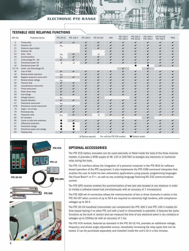
TESTABLE IEEE RELAYING FUNCTIONSIEEE No. Protective device PTE-50-CE PTE-100-V PTE-300-V PTE-50-CET UNO PTE-100-V
PTE-100-CPTE-300-VPTE-50-CE
PTE-300-VPTE-100-C
PTE-50-CET PTE-100-V TRES
2 Timing relay ✔ ✔ ✔ ✔ ✔ ✔ ✔ ✔ ✔ ✔
21 Distance 1Ø Pro ✔ ✔ ✔ ✔ ✔ ✔ ✔ ✔
21 Distance (open delta) ✔ ✔ ✔ ✔ ✔ ✔ ✔ ✔
21 Distance 3Ø ✔ ✔ ✔ ✔ ✔ ✔ ✔
24 Volts / Herz Pro ✔ ✔ ❏ ✔ ✔ ✔ ✔ ✔ ✔
25 Synchronization Pro ✔ ✔ ✔ ✔ ✔ ✔ ✔ ✔ ✔
27 Undervoltage AC / DC ✔ ✔ ✔ ✔ ✔ ✔ ✔ ✔ ✔ ✔
32 Directional power 1Ø ❏ ❏ ✔ ✔ ✔ ✔ ✔ ✔ ✔ ✔
32 Directional power 3Ø ■ ■ ✔ ✔
37/76 Under- and Overvoltage DC ✔ ✔
40 Loss of field ✔ ✔ ✔ ✔ ✔ ✔ ✔ ✔ ✔ ✔
46 Reverse phase sequence Pro ✔ ✔ ✔ ✔ ✔ ✔ ✔ ✔
46N Negative sequence overcurrent ✔ ✔ ✔ ✔ ✔ ✔ ✔ ✔ ✔ ✔
47 Reverse phase voltage Pro ✔ ✔ ✔ ✔ ✔ ✔ ✔ ✔
49 Thermal relay ✔ ✔ ✔ ✔ ✔ ✔ ✔ ✔ ✔ ✔
50 Instantaneous overcurrent ✔ ✔ ✔ ✔ ✔ ✔ ✔ ✔ ✔ ✔
51 Timed overcurrent ✔ ✔ ✔ ✔ ✔ ✔ ✔ ✔ ✔ ✔
55 Power factor relay ✔ ✔ ✔ ✔ ✔ ✔ ✔ ✔ ✔ ✔
59 Overvoltage ✔ ✔ ✔ ✔ ✔ ✔ ✔ ✔ ✔ ✔
60 Voltage balance Pro ✔ ✔ ✔ ✔ ✔ ✔
64 Neutral detection ✔ ✔ ✔ ✔ ✔ ✔ ✔ ✔ ✔ ✔
67 Directional overcurrent Pro ✔ ✔ ✔ ✔ ✔ ✔ ✔ ✔
67N Directional neutral overcurrent ✔ ✔ ✔ ✔ ✔ ✔ ✔ ✔ ✔ ✔
78 Angle / out of step ✔ ✔ ✔ ✔ ✔ ✔ ✔ ✔ ✔ ✔
79 Reclosing relay ✔ ✔ ✔ ✔ ✔ ✔ ✔ ✔ ✔ ✔
81 Frequency relay Pro ✔ ✔ ❏ ✔ ✔ ✔ ✔ ✔ ✔
82 DC reclosers. ✔ ✔
85 Carrier or pilot wire protection ■ ✔ ✔ ✔ ✔ ✔ ✔ ✔ ✔ ✔
87 Differential protection ■ ■ ✔ ✔ ✔ ✔ ✔ ✔ ✔ ✔
91 Directional voltage ■ ■ ✔ ✔ ✔ ✔ ✔ ✔ ✔ ✔
92 Directional power and voltage ■ ■ ✔ ✔ ✔ ✔ ✔ ✔ ✔ ✔
94 Tripping relay ✔ ✔ ✔ ✔ ✔ ✔ ✔ ✔ ✔ ✔
❏ Options required Pro: with the PTE-FCN module ■ Partially tested
OPTIONAL ACCESSORIESThe PTE-FCG battery simulator can be used externally or fitted inside the lead of the three-channelmodels. It provides a 60W supply of 48, 125 or 250 VDC to energize any electronic or numericalrelay during the tests.
The PTE-12 interface allows the integration of a personal computer in the PTE-BUS for softwarebased operation of the PTE equipment. It also implements the PTE-COM command interpreter thatenables the user to build his own automation applications using popular programming languageslike Visual Basic® or C++, as well as any scripting language featuring RS-232 communicationscontrol.
The PTE-GPS receiver enables the synchronization of two test sets located at any distance in orderto initiate a software-based test simultaneously with an accuracy of 1 microsecond.
The PTE-SER set of connectors allows the interconnection of two or three channels in series in thePTE-50-CET when currents of up to 50 A are required on extremely high burdens, with compliancevoltages up to 60 V.
The PTE-30-CH handheld chronometer can complement the PTE-300-V and PTE-100-V models fortime-based testing if no other PTE unit with a built-in chronometer is available. It features the samefunctions as the built-in version and can measure the time of any electrical event in dry contacts orvoltages up to 250Vac/dc with an accuracy of 1 ms.
The PTE-FCN module, featured as standard in the PTE-50-CE Pro, provides an additional voltage,frequency and phase angle adjustable source, remarkably increasing the relay types that can betested. It can be purchased separately and installed inside the unit's lid in a few minutes.
PTE-FCG
PTE-12
PTE-SER
PTE-30-CHPTE-GPS
Gama PTEs ingles v5_SMC fichas 30/5/15 13:23 Página 6
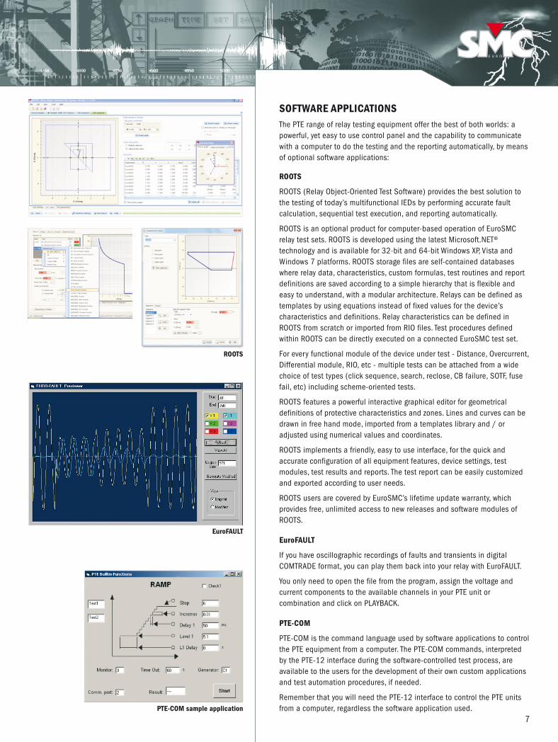
SOFTWARE APPLICATIONSThe PTE range of relay testing equipment offer the best of both worlds: apowerful, yet easy to use control panel and the capability to communicatewith a computer to do the testing and the reporting automatically, by meansof optional software applications:
ROOTS
ROOTS (Relay Object-Oriented Test Software) provides the best solution tothe testing of today’s multifunctional IEDs by performing accurate faultcalculation, sequential test execution, and reporting automatically.
ROOTS is an optional product for computer-based operation of EuroSMCrelay test sets. ROOTS is developed using the latest Microsoft.NET®technology and is available for 32-bit and 64-bit Windows XP, Vista andWindows 7 platforms. ROOTS storage files are self-contained databaseswhere relay data, characteristics, custom formulas, test routines and reportdefinitions are saved according to a simple hierarchy that is flexible andeasy to understand, with a modular architecture. Relays can be defined astemplates by using equations instead of fixed values for the device’scharacteristics and definitions. Relay characteristics can be defined inROOTS from scratch or imported from RIO files. Test procedures definedwithin ROOTS can be directly executed on a connected EuroSMC test set.
For every functional module of the device under test - Distance, Overcurrent,Differential module, RIO, etc - multiple tests can be attached from a widechoice of test types (click sequence, search, reclose, CB failure, SOTF, fusefail, etc) including scheme-oriented tests.
ROOTS features a powerful interactive graphical editor for geometricaldefinitions of protective characteristics and zones. Lines and curves can bedrawn in free hand mode, imported from a templates library and / oradjusted using numerical values and coordinates.
ROOTS implements a friendly, easy to use interface, for the quick andaccurate configuration of all equipment features, device settings, testmodules, test results and reports. The test report can be easily customizedand exported according to user needs.
ROOTS users are covered by EuroSMC’s lifetime update warranty, whichprovides free, unlimited access to new releases and software modules ofROOTS.
EuroFAULT
If you have oscillographic recordings of faults and transients in digitalCOMTRADE format, you can play them back into your relay with EuroFAULT.
You only need to open the file from the program, assign the voltage andcurrent components to the available channels in your PTE unit orcombination and click on PLAYBACK.
PTE-COM
PTE-COM is the command language used by software applications to controlthe PTE equipment from a computer. The PTE-COM commands, interpretedby the PTE-12 interface during the software-controlled test process, areavailable to the users for the development of their own custom applicationsand test automation procedures, if needed.
Remember that you will need the PTE-12 interface to control the PTE unitsfrom a computer, regardless the software application used.
7
ROOTS
EuroFAULT
PTE-COM sample application
Gama PTEs ingles v5_SMC fichas 30/5/15 13:23 Página 7

SPECIFICATIONS
EuroSMC, S.A.Polígono industrial P-29, Calle Buril, 6928400 Collado Villalba. Madrid (Spain).Tels: +34 91 849 89 80 Fax: +34 91 851 25 53 www.eurosmc.com e-mail: [email protected]
DISTRIBUTED BY:
REVERSIBLE OUTPUT CHANNELS
STANDARD ACCESSORIESComplete 2-m / 6,5 ft. test lead set
1.5-m / 4,9 ft. power cord
4-mm terminal adapters
4-mm crocodile clip set
RS-232 communications cable
PTE BUS interconnection cable
Set of replacement fuses
Coaxial BNC to 4-mm connection cable
Nylon bag for test set and accessories
Calibration software
User manual in English
Certificate of calibration
TRIP MONITORDry contact input Open circuit voltage: 10.2 Vdc
Short circuit current: 25 mA
Fuse protected
Voltage input 5 - 250 Vac/dc
Impedance: 19 kΩ
Fuse protected
DIGITAL CHRONOMETER (PTE-50-CET, PTE-50-CE)Range 0.001 - 99999 s. o 0.1 – 9999.9 cycles
Accuracy ±0.01% of reading ±1 digit
Start modes
Output ON or OFFPre-fault / fault state switching
PTE BUS eventExternal START signal
Stop modesNO or NC contactVoltage ON / OFF
PTE BUS event
FREQUENCY GENERATOR (PTE-300-V, PTE-100-V)Modo normal Modo diferencial
Range 40-420 Hz 0.001-10 Hz
Resolution 0.01 / 0.1 / 1 Hz 0.001 / 0.01 / 0.1 Hz
Accuracy 1 digit ±0.003 Hz 1 digit ±0.001 Hz
Ramp limits 0.1 – 10.0 Hz/s. _
Ramp lapses 0.1 – 10.0 s. _
EXTERNAL REFERENCE INPUTVoltage input Current input
Input impedance 47 kΩ 25 mΩ
Signal range 5 – 300 Vac 0.1 – 25 Aac
Frequency range 40 - 70 Hz
PTE-50-CET PTE-50-CE PTE-300-V PTE-100-VNumber of channels 3 1 3 1
Interconnections Serial or parallel Serial or parallel
Current ranges 0-0.330 A / 0-8.000A / 0-25.00A / 0-50.00A 0-0.330A / 0-8.000A
Voltage ranges 0-6.25V / 0-150.0V 0-6.25V / 0-150 V / 0-300V
Harmonics generated 1st – 7th automatic in each channel Manual, up to 420 Hz
Phase angle 0-359.9º
Frequency range Parametric: 40.00-420.0 Hz Transient: 0.5-5000 Hz
Power per channel 100 VA
Accuracy ±0.5%
Distortion 1% máx.
ELECTRONIC PTE RANGE
Plea
se n
ote:
Due
to th
e co
ntin
uous
rese
arch
and
dev
elop
men
t by
Euro
SMC,
spe
cific
atio
ns in
this
cat
alog
may
be
chan
ged
with
out p
revi
ous
notic
e.
PT
ECCE
N -
Vers
ion
5
PTE-FCN OPTIONOutput power 30 VA (70 – 140 Vac)
Voltage output 0 – 140 Vac (res.: 0.1V)
Max. current 0.45 A (0 – 70 Vac)
Phase angle 0 – 359.9º (res.: 0.1º, Vout> 5V)
Frequency 40 – 70 Hz (res.: 0.1 Hz)
Phase reference AC supply or internal generator
GENERALPTE-50-CET PTE-300-V PTE-50-CE PTE-100-V
Weight 25 Kg / 55.1 lb. 22 Kg. / 48.5 lb. 13.5 Kg. / 29.7 lb. 13.5 Kg. / 29.7 lb.
Dimensions (mm)inches
442 x 327 x 20017.4 x 12.8 x 7.8 in
300 x 200 x 20011.8 x 7.8 x 7.8
Auxiliary voltage output 110 Vca / 0.3 A máx.
Supply power 230 / 110 Vca ±10%
Temperature range Storage : -20 to 70ºC / -4º F - 158º F / Operation: 0 to 50ºC / 32ºF - 122º F
Gama PTEs ingles v5_SMC fichas 30/5/15 13:23 Página 8