protonode fpc-n34 and protonode fpc-n35 and lonworks files/pv500-43.pdf · web configurator...
TRANSCRIPT

PV500-43 03/2017
Document Revision: 2 Web Configurator
Template Revision: 51
ProtoNode FPC-N34 and ProtoNode FPC-N35 Startup Guide
For Interfacing Customer Products: OnTrac, TempTrac, XR10CX and EOS Water Heater
To Building Automation Systems: BACnet MS/TP, BACnet/IP, Modbus TCP/IP, Modbus RTU
and LonWorks
APPLICABILITY & EFFECTIVITY
Explains ProtoNode FPC-N34 and FPC-N35 hardware and how to install it.
The instructions are effective for the above as of January 2016.

PVI ProtoNode Startup Guide
Page 2 of 40 PV500-43 03/2017
Technical Support: Thank you for purchasing the ProtoNode for PVI. Please call PVI for Technical support of the ProtoNode product. Sierra Monitor Corporation does not provide direct support. If PVI needs to escalate the concern, they will contact Sierra Monitor Corporation for assistance. Support Contact Information:
PVI Industries, LLC 3209 Galvez Avenue Fort Worth, TX 76111 Customer Service:
(800) 433-5654 Email: [email protected] Website: www.PVI.com

PVI ProtoNode Startup Guide
Page 3 of 40 PV500-43 03/2017
A Quick Start Guide
1. Record the information about the unit. (Section 2.1)
2. Set the device’s Modbus RTU serial settings (i.e. baud rate, parity, stop bits and Modbus Node-
ID’s for each of the devices that will be connected to ProtoNode FPC-N34 or FPC-N35. (Section
2.3)
3. ProtoNode FPC-N34 units: Select the Field Protocol (BACnet MS/TP, BACnet/IP, Modbus TCP/IP
or Modbus RTU) on the S Bank Dip Switches. (Section 2.4)
4. BACnet MS/TP (FPC-N34): Set the MAC Address on DIP Switch Bank A. (Section 2.5.1)
5. BACnet MS/TP or BACnet/IP (FPC-N34): Set the BACnet Device Instance. (Section 2.5.2)
6. Metasys N2 (FPC-N34): Set the Node-ID. (Section 2.5.3)
7. BACnet MS/TP (FPC-N34): Set the BAUD rate of the BACnet MS/TP Field Protocol on DIP Switch
Bank B. (Section 2.5.4)
8. Connect ProtoNode FPC-N34’s 3 pin RS-485 port to the Field Protocol cabling,
or connect ProtoNode FPC-N35’s 2 pin LonWorks port to the Field Protocol cabling. (Section
3.1)
9. Connect ProtoNode 6 pin RS-485 connector to the Modbus RS-485 network that is connected to
each of the devices. (Section 3.2)
10. Connect Power to ProtoNode 6 pin connector. (Section 3.5)
11. Use a browser to access the ProtoNode’s embedded tool, which is referred to in this manual as the
Web Configurator, to select the devices that will be attached to ProtoNode and set the current
Modbus Node-ID for each these products. Once the devices are selected, the ProtoNode
Automatically builds and loads the Configuration for the devices. (Section 4)
12. BACnet/IP or Modbus TCP/IP (FPC-N34): Use a browser to access the ProtoNode Web
Configurator to change the IP Address. No changes to the configuration are necessary. (Section
5)
13. LonWorks (FPC-N35): The ProtoNode must be commissioned on the LonWorks Network. This
needs to be done by the LonWorks administrator using a LonWorks Commissioning tool. (Section
7)

PVI ProtoNode Startup Guide
Page 4 of 40 PV500-43 03/2017
Certifications
BTL MARK – BACNET TESTING LABORATORY
LONMARK CERTIFICATION
The BTL Mark on ProtoNode is a symbol that indicates that a product
has passed a series of rigorous tests conducted by an independent
laboratory which verifies that the product correctly implements the
BACnet features claimed in the listing. The mark is a symbol of a high-
quality BACnet product.
Go to http://www.BACnetInternational.net/btl/ for more information
about the BACnet Testing Laboratory. Click here for BACnet PIC
Statement.
LonMark International is the recognized authority for certification, education,
and promotion of interoperability standards for the benefit of manufacturers,
integrators and end users. LonMark International has developed extensive
product certification standards and tests to provide the integrator and user
with confidence that products from multiple manufacturers utilizing LonMark
devices work together. Sierra Monitor has more LonMark Certified gateways
than any other gateway manufacturer, including the ProtoCessor,
ProtoCarrier and ProtoNode for OEM applications and the full featured,
configurable gateways.

PVI ProtoNode Startup Guide
Page 5 of 40 PV500-43 03/2017
TABLE OF CONTENTS
1 Introduction .......................................................................................................................................... 7 1.1 ProtoNode Gateway ....................................................................................................................... 7
2 BACnet/LonWorks Setup for ProtoCessor ProtoNode FPC-N34/FPC-N35 .................................... 8 2.1 Record Identification Data .............................................................................................................. 8 2.2 Point Count Capacity and Registers per Device ............................................................................ 8 2.3 Configuring Device Communications ............................................................................................. 9
2.3.1 Set Modbus COM setting on all of the devices connected to the ProtoNode ........................... 9 2.3.2 Set Modbus Node-ID for each of the Devices attached to the ProtoNode ............................... 9
2.4 Selecting the Desired Field Protocol ............................................................................................ 10 2.5 BMS Network Settings: MAC Address, Device Instance and Baud Rate .................................... 11
2.5.1 BACnet MS/TP (FPC-N34): Setting the MAC Address for BMS Network .............................. 11 2.5.2 BACnet MS/TP and BACnet/IP (FPC-N34): Setting the Device Instance .............................. 12 2.5.3 Modbus TCP/IP (FPC-N34): Setting the Node-ID ................................................... 12 2.5.4 BACnet MS/TP (FPC-N34): Setting the Baud Rate for BMS Network .................................... 13
3 Interfacing ProtoNode to Devices .................................................................................................... 14 3.1 ProtoNode FPC-N34 and FPC-N35 Showing Connection Ports .................................................. 14 3.2 Device Connections to ProtoNode ............................................................................................... 15
3.2.1 Biasing the Modbus RS-485 Device Network ......................................................................... 16 3.2.2 End of Line Termination Switch for the Modbus RS-485 Device Network.............................. 17
3.3 BACnet MS/TP (FPC-N34): Wiring Field Port to RS-485 Network .............................................. 18 3.4 LonWorks (FPC-N35): Wiring Field Port to LonWorks Network ................................................... 18 3.5 Power-Up ProtoNode.................................................................................................................... 19
4 Use ProtoNode Web Configurator to Select Device Profiles ........................................................ 20 4.1 Connect the PC to ProtoNode via the Ethernet Port .................................................................... 20 4.2 Connecting to ProtoNode Web Configurator ................................................................................ 21
4.2.1 Selecting Profiles for Devices Connected to ProtoNode......................................................... 21 4.3 BACnet/IP and Modbus TCP/IP: Setting IP Address for Field Network ....................................... 23
5 BACnet MS/TP and BACnet/IP: Setting Node_Offset to Assign Specific Device Instances ..... 25
6 How to Start the Installation Over: Clearing Profiles ..................................................................... 26
7 LonWorks (FPC-N35): Commissioning ProtoNode on a lonworks Network ............................... 27 7.1 Commissioning ProtoNode FPC-N35 on a LonWorks Network ................................................... 27
7.1.1 Instructions to Download XIF File from ProtoNode FPC-N35 Using Browser ........................ 27
8 CAS BACnet Explorer for Validating ProtoNode in the Field ........................................................ 29 8.1 Downloading the CAS Explorer and Requesting an Activation Key ............................................. 29 8.2 CAS BACnet Setup....................................................................................................................... 30
8.2.1 CAS BACnet MS/TP Setup ..................................................................................................... 30 8.2.2 CAS BACnet BACnet/IP Setup ............................................................................................... 30
Appendix A. Troubleshooting .................................................................................................................. 31 Lost or Incorrect IP Address ............................................................................................ 31 Viewing Diagnostic information ........................................................................................ 32 Check Wiring and Settings............................................................................................... 33 Take Diagnostic Capture With the FieldServer Utilities ................................................... 33 BACnet: Setting Network_Number for more than one ProtoNode on Subnet ................. 36 LED Diagnostics for Communications Between ProtoNode and Devices ....................... 37 Passwords ....................................................................................................................... 37
Appendix B. Vendor Information - PVI .................................................................................................... 38 OnTrac Modbus TCP/IP Mappings to BACnet and LonWorks ........................................ 38 TempTrac Modbus RTU Mappings to BACnet and LonWorks ........................................ 38 XR10CX Modbus RTU Mappings to BACnet and LonWorks .......................................... 38 EOS Water Heater Modbus RTU Mappings to BACnet and LonWorks .......................... 38

PVI ProtoNode Startup Guide
Page 6 of 40 PV500-43 03/2017
Appendix C. “A” Bank DIP Switch Settings ........................................................................................... 39
Appendix D. Reference ............................................................................................................................. 40 Specifications ................................................................................................................... 40
Appendix D.1.1. Compliance with UL Regulations ........................................................................... 40
LIST OF FIGURES
Figure 1: ProtoCessor Part Numbers ............................................................................................................ 8 Figure 2: Supported Point Count Capacity ................................................................................................... 8 Figure 3: Modbus Registers per Device ........................................................................................................ 8 Figure 4: Modbus COM Settings ................................................................................................................... 9 Figure 5: S Bank DIP Switches ................................................................................................................ 10 Figure 6: MAC Address DIP Switches ........................................................................................................ 11 Figure 7: Baud Rate DIP Switches ............................................................................................................. 13 Figure 8: BMS Baud Rate ........................................................................................................................... 13 Figure 9: ProtoNode BACnet FPC-N34 (upper) and ProtoNode FPC-N35 (lower) .................................... 14 Figure 10: Power and RS-485 Connections ............................................................................................... 15 Figure 11: Modbus RS-485 Biasing Switch on the ProtoNode N34 (left) and ProtoNode N35 (right)........ 16 Figure 12: Modbus RS-485 End-Of-Line Termination Switch on the ProtoNode N34 (left) and ....... 17 Figure 13: Connection from ProtoNode to RS-485 Field Network ....................................................... 18 Figure 14: RS-485 BMS Network EOL Switch ............................................................................................ 18 Figure 15: LonWorks Terminal ................................................................................................................ 18 Figure 16: Required current draw for the ProtoNode .................................................................................. 19 Figure 17: Power Connections ................................................................................................................ 19 Figure 18: Web Configurator Showing no Active Profiles ........................................................................... 21 Figure 19: Web Configurator Showing Available Profile Selection ..................................................... 22 Figure 20: Web Configurator Showing an Active Profile Addition ...................................................... 22 Figure 21: Web Configurator Screen ...................................................................................................... 23 Figure 22: Changing IP Address via Web GUI ....................................................................................... 24 Figure 23: Web Configurator screen ....................................................................................................... 25 Figure 24: LonWorks Service Pin Location ............................................................................................ 27 Figure 25: Sample of Fserver.XIF File Generated .................................................................................. 28 Figure 26: Downloading the CAS Explorer ............................................................................................. 29 Figure 27: Requesting CAS Activation Key............................................................................................ 29 Figure 28: Ethernet Port Location ............................................................................................................... 31 Figure 29: Error messages screen .......................................................................................................... 32 Figure 30: Ethernet Port Location ............................................................................................................... 33 Figure 31: Web Configurator – Setting Network Number for BACnet ................................................. 36 Figure 32: Diagnostic LEDs ..................................................................................................................... 37 Figure 33: Specifications ............................................................................................................................. 40

PVI ProtoNode Startup Guide
Page 7 of 40 PV500-43 03/2017
1 INTRODUCTION
1.1 ProtoNode Gateway
ProtoNode is an external, high performance Building Automation multi-protocol gateway that is
preconfigured to automatically communicate between PVI’s products (hereafter called “device”)
connected to the ProtoNode and automatically configures them for BACnet®1MS/TP, BACnet/IP
Modbus TCP/IP, Modbus RTU or LonWorks®2.
It is not necessary to download any configuration files to support the required applications. The
ProtoNode is pre-loaded with tested Profiles/Configurations for the supported devices.
1 BACnet is a registered trademark of ASHRAE 2 LonWorks is a registered trademark of Echelon Corporation

PVI ProtoNode Startup Guide
Page 8 of 40 PV500-43 03/2017
2 BACNET/LONWORKS SETUP FOR PROTOCESSOR PROTONODE FPC-
N34/FPC-N35
2.1 Record Identif ication Data
Each ProtoNode has a unique part number located on the side or the back of the unit. This number
should be recorded, as it may be required for technical support. The numbers are as follows:
Model Part Number
ProtoNode FPC-N34 FPC-N34-0481
ProtoNode FPC-N35 FPC-N35-0589
Figure 1: ProtoCessor Part Numbers
FPC-N34 units have the following 3 ports: RS-485 + Ethernet + RS-485
FPC-N35 units have the following 3 ports: LonWorks + Ethernet + RS-485
2.2 Point Count Capacity and Registers per Device
The total number of Modbus Registers presented by all of the devices attached to the
ProtoNode cannot exceed:
Part number Total Registers
FPC-N34-0481 1,500
FPC-N35-0589 1,500
Figure 2: Supported Point Count Capacity
Devices Registers Per Device
OnTrac 757
TempTrac 38
XR10CX 11
EOS Water Heater 63
Figure 3: Modbus Registers per Device

PVI ProtoNode Startup Guide
Page 9 of 40 PV500-43 03/2017
2.3 Configuring Device Communications
2.3.1 Set Modbus COM setting on all of the devices connected to the ProtoNode
All of the serial devices connected to ProtoNode MUST have the same Baud Rate, Data Bits,
Stop Bits, and Parity settings.
Modbus TCP/IP device must be on the same subnet as the ProtoNode.
Figure 4 specifies the device serial port settings required to communicate with the ProtoNode.
Serial Port Setting OnTrac TempTrac XR10CX EOS Water Heater
Protocol Modbus TCP/IP Modbus RTU Modbus RTU Modbus RTU
Baud Rate N/A 9600 9600 19200
Parity N/A None None Even
Data Bits N/A 8 8 8
Stop Bits N/A 1 1 1
Figure 4: Modbus COM Settings
2.3.2 Set Modbus Node-ID for each of the Devices attached to the ProtoNode
Set Modbus RTU Node-ID for each of the devices attached to ProtoNode. The Modbus Node-
ID’s need to be uniquely assigned between 1 and 255.
o The Modbus Node-ID that is assigned for each device needs to be documented.
The Modbus Node-ID’s assigned are used for designating the Device Instance for
BACnet/IP and BACnet MS/TP (Section 2.5.2)
Modbus TCP/IP Node-ID will be set to same value as the Node-ID of the Modbus RTU device.

PVI ProtoNode Startup Guide
Page 10 of 40 PV500-43 03/2017
2.4 Selecting the Desired Field Protocol
ProtoNode FPC-N34 units use the “S” bank of DIP switches (S0 – S3) to select the Field
Protocol.
o See the table in Figure 5 for the switch settings to select BACnet MS/TP, BACnet/IP,
Modbus TCP/IP or Modbus RTU.
o The OFF position is when the DIP switches are set closest to the outside of the box.
ProtoNode FPC-N35 units do not use the “S” bank DIP switches (S0 – S3) to select a Field
Protocol.
o On ProtoNode FPC-N35 units, these switches are disabled; the Field Protocol is always
LonWorks.
ProtoNode FPC-N34 S Bank DIP Switches
Profile S0 S1 S2 S3
BACnet/IP Off Off Off Off
BACnet MS/TP On Off Off Off
Modbus TCP/IP Off On Off Off
Modbus RTU On On Off Off
S0 – S3 DIP Switches
S Bank DIP Switch Location
BACnet MS/TP, BACnet/IP, Modbus TCP/IP, or Modbus RTU for ProtoNode FPC-N34
Figure 5: S Bank DIP Switches
S0
S1
S2
S3

PVI ProtoNode Startup Guide
Page 11 of 40 PV500-43 03/2017
2.5 BMS Network Settings: MAC Address, Device Instance and Baud Rate
2.5.1 BACnet MS/TP (FPC-N34): Setting the MAC Address for BMS Network
Only 1 MAC address is set for ProtoNode regardless of how many devices are connected to
ProtoNode.
Set the BACnet MS/TP MAC address of the ProtoNode to a value between 1 to 127 (Master
MAC address); this is so that the BMS Front End can find ProtoNode via BACnet auto
discovery.
NOTE: Never set a BACnet MS/TP MAC Address of the ProtoNode to a value from 128 to 255.
Addresses from 128 to 255 are Slave Addresses and can not be discovered by BMS Front
Ends that support Auto-Discovery of BACnet MS/TP devices.
Set “A” bank DIP switches A0 – A7 to assign a MAC Address to the ProtoNode for BACnet
MS/TP.
Please refer to Error! Reference source not found. for the complete range of MAC Addresses
nd DIP switch settings.
When using Modbus TCP/IP, the A Bank of DIP switches are disabled and not used. They
should be set to OFF.
A0
A1
A2
A3
A4
A5
A6
A7
NOTE: When setting DIP Switches, please ensure that power to the board is OFF.
Figure 6: MAC Address DIP Switches
PVI ProtoNode Startup Guide
Page 12 of 40 PV500-43 03/2017
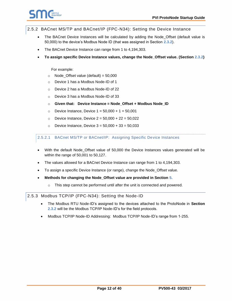
2.5.2 BACnet MS/TP and BACnet/IP (FPC-N34): Setting the Device Instance
The BACnet Device Instances will be calculated by adding the Node_Offset (default value is
50,000) to the device’s Modbus Node ID (that was assigned in Section 2.3.2).
The BACnet Device Instance can range from 1 to 4,194,303.
To assign specific Device Instance values, change the Node_Offset value. (Section 2.3.2)
For example:
o Node_Offset value (default) = 50,000
o Device 1 has a Modbus Node-ID of 1
o Device 2 has a Modbus Node-ID of 22
o Device 3 has a Modbus Node-ID of 33
o Given that: Device Instance = Node_Offset + Modbus Node_ID
o Device Instance, Device 1 = 50,000 + 1 = 50,001
o Device Instance, Device 2 = 50,000 + 22 = 50,022
o Device Instance, Device 3 = 50,000 + 33 = 50,033
2.5.2.1 BACnet MS/TP or BACnet/IP: Assigning Specific Device Instances
With the default Node_Offset value of 50,000 the Device Instances values generated will be
within the range of 50,001 to 50,127.
The values allowed for a BACnet Device Instance can range from 1 to 4,194,303.
To assign a specific Device Instance (or range), change the Node_Offset value.
Methods for changing the Node_Offset value are provided in Section 5.
o This step cannot be performed until after the unit is connected and powered.
2.5.3 Modbus TCP/IP (FPC-N34): Setting the Node-ID
The Modbus RTU Node-ID’s assigned to the devices attached to the ProtoNode in Section
2.3.2 will be the Modbus TCP/IP Node-ID’s for the field protocols.
Modbus TCP/IP Node-ID Addressing: Modbus TCP/IP Node-ID’s range from 1-255.
PVI ProtoNode Startup Guide
Page 13 of 40 PV500-43 03/2017
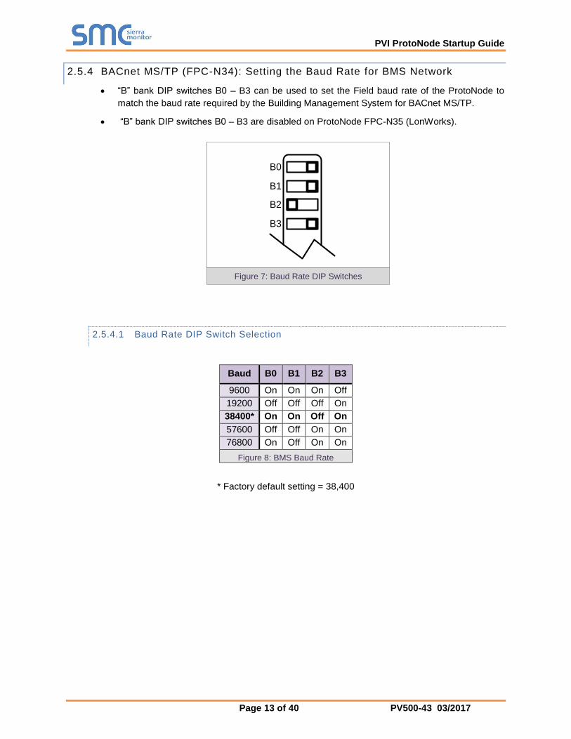
2.5.4 BACnet MS/TP (FPC-N34): Setting the Baud Rate for BMS Network
“B” bank DIP switches B0 – B3 can be used to set the Field baud rate of the ProtoNode to
match the baud rate required by the Building Management System for BACnet MS/TP.
“B” bank DIP switches B0 – B3 are disabled on ProtoNode FPC-N35 (LonWorks).
B0
B1
B2
B3
2.5.4.1 Baud Rate DIP Switch Selection
Baud B0 B1 B2 B3
9600 On On On Off
19200 Off Off Off On
38400* On On Off On
57600 Off Off On On
76800 On Off On On
Figure 8: BMS Baud Rate
* Factory default setting = 38,400
Figure 7: Baud Rate DIP Switches

PVI ProtoNode Startup Guide
Page 14 of 40 PV500-43 03/2017
3 INTERFACING PROTONODE TO DEVICES
3.1 ProtoNode FPC-N34 and FPC-N35 Showing Connection Ports
Figure 9: ProtoNode BACnet FPC-N34 (upper) and ProtoNode FPC-N35 (lower)

PVI ProtoNode Startup Guide
Page 15 of 40 PV500-43 03/2017
3.2 Device Connections to ProtoNode
ProtoNode 6 Pin Phoenix connector for RS-485 Devices
The 6 pin Phoenix connector is the same for ProtoNode FPC-N34 (BACnet) and FPC-N35
(LonWorks).
Pins 1 through 3 are for Modbus RS-485 devices.
o The RS-485 GND (Pin 3) is not typically connected.
Pins 4 through 6 are for power. Do not connect power (wait until Section 3.5).
Device Pins ProtoNode Pin
#
Pin
assignment
Pin RS-485 + Pin 1 RS-485 +
Pin RS-485 - Pin 2 RS-485 -
Pin GND Pin 3 RS-485 GND
Power In (+) Pin 4 V +
Power In (-) Pin 5 V -
Frame Ground Pin 6 FRAME GND
Figure 10: Power and RS-485 Connections

PVI ProtoNode Startup Guide
Page 16 of 40 PV500-43 03/2017
3.2.1 Biasing the Modbus RS-485 Device Network
An RS-485 network with more than one device needs to have biasing to ensure proper
communication. The biasing only needs to be done on one device.
The ProtoNode has 510 Ohm resistors that can be used to set the biasing. The ProtoNode’s
default positions from the factory for the biasing jumpers are OFF.
The OFF position is when the 2 RED biasing jumpers straddle the 4 pins closest to the outside
of the board of the ProtoNode. (Figure 11).
Only turn biasing ON:
o IF the BMS cannot see more than one device connected to the ProtoNode
o AND all the settings (Modbus COM settings, wiring, and DIP switches) have been
checked.
To turn biasing ON, move the 2 RED biasing jumpers to straddle the 4 pins closest to the inside
of the board of the ProtoNode.
RS-485 Bias Switch
(off)
Figure 11: Modbus RS-485 Biasing Switch on the ProtoNode N34 (left) and ProtoNode N35 (right)

PVI ProtoNode Startup Guide
Page 17 of 40 PV500-43 03/2017
3.2.2 End of Line Termination Switch for the Modbus RS-485 Device Network
On long RS-485 cabling runs, the RS-485 trunk must be properly terminated at each end.
The ProtoNode has an End Of Line (EOL) blue jumper. The default setting for this Blue EOL
switch is OFF with the jumper straddling the pins closest to the inside of the board of the
ProtoNode.
o On short cabling runs the EOL switch does not to need to be turned ON.
If the ProtoNode is placed at one of the ends of the trunk, set the blue EOL jumper to the
ON position straddling the pins closest to the outside of the board of the ProtoNode.
Always leave the single Red Jumper in the A position (default factory setting).
Modbus RS-485
EOL Switch
(off)
Leave in Position A
Figure 12: Modbus RS-485 End-Of-Line Termination Switch on the ProtoNode N34 (left) and ProtoNode N35 (right)
PVI ProtoNode Startup Guide
Page 18 of 40 PV500-43 03/2017
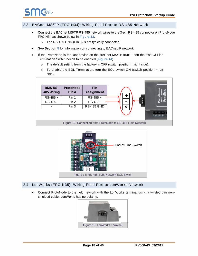
3.3 BACnet MS/TP (FPC-N34): Wiring Field Port to RS-485 Network
Connect the BACnet MS/TP RS-485 network wires to the 3-pin RS-485 connector on ProtoNode
FPC-N34 as shown below in Figure 13.
o The RS-485 GND (Pin 3) is not typically connected.
See Section 5 for information on connecting to BACnet/IP network.
If the ProtoNode is the last device on the BACnet MS/TP trunk, then the End-Of-Line
Termination Switch needs to be enabled (Figure 14).
o The default setting from the factory is OFF (switch position = right side).
o To enable the EOL Termination, turn the EOL switch ON (switch position = left
side).
3.4 LonWorks (FPC-N35): Wiring Field Port to LonWorks Network
Connect ProtoNode to the field network with the LonWorks terminal using a twisted pair non-
shielded cable. LonWorks has no polarity.
BMS RS-
485 Wiring
ProtoNode
Pin #
Pin
Assignment
RS-485 + Pin 1 RS-485 +
RS-485 - Pin 2 RS-485 -
- Pin 3 RS-485 GND
Figure 15: LonWorks Terminal
End-of-Line Switch
Figure 14: RS-485 BMS Network EOL Switch
G
-
+
Figure 13: Connection from ProtoNode to RS-485 Field Network

PVI ProtoNode Startup Guide
Page 19 of 40 PV500-43 03/2017
3.5 Power-Up ProtoNode
Apply power to ProtoNode as show below in Figure 17. Ensure that the power supply used complies
with the specifications provided in Appendix D.1.
ProtoNode accepts either 9-30VDC or 12-24 VAC on pins 4 and 5.
Frame GND should be connected.
Power Requirement for ProtoNode External Gateway
Current Draw Type
ProtoNode Family 12VDC/VAC 24VDC/VAC 30VDC
FPC – N34 170mA 100mA 80mA
FPC – N34 (Maximum) 240mA 140mA 100mA
FPC – N35 (Typical) 210mA 130mA 90mA
FPC – N35 (Maximum) 250mA 170mA 110mA
NOTE: These values are ‘nominal’ and a safety margin should be added to the power supply of the host system. A safety margin of 25% is recommended.
Figure 16: Required current draw for the ProtoNode
Power to
ProtoNode
ProtoNode
Pin #
Pin
Assignment
Power In (+) Pin 4 V +
Power In (-) Pin 5 V -
Frame Ground Pin 6 FRAME GND
Figure 17: Power Connections

PVI ProtoNode Startup Guide
Page 20 of 40 PV500-43 03/2017
4 USE PROTONODE WEB CONFIGURATOR TO SELECT DEVICE PROFILES
4.1 Connect the PC to ProtoNode via the Ethernet Port
Connect a CAT5 Ethernet cable (Straight through or Cross-Over) between the PC and ProtoNode.
The Default IP Address of ProtoNode is 192.168.1.24, Subnet Mask is 255.255.255.0. If the PC
and ProtoNode are on different IP Networks, assign a static IP Address to the PC on the
192.168.1.xxx network.
Go to > >
Right-click on Local Area Connection > Properties
Highlight >
Select: Use the following IP Address
Click twice

PVI ProtoNode Startup Guide
Page 21 of 40 PV500-43 03/2017
4.2 Connecting to ProtoNode Web Configurator
After setting a local PC on the same subnet as the ProtoNode (Section 4.1), open a web browser
on the PC and enter the IP Address of the ProtoNode; the default address is 192.168.1.24.
If the IP Address of the ProtoNode has been changed by previous configuration, the assigned IP
Address must be gathered from the network administrator.
4.2.1 Selecting Profiles for Devices Connected to ProtoNode
NOTE: If Modbus TCP/IP was selected in Section 2.4 for the Field/BMS protocol, skip this section. Device profiles are NOT used for Modbus TCP/IP.
In the Web Configurator, the Active Profiles section is shown on the lower left side of the screen.
The Active Profiles section lists the currently active device profiles, including previous Web
Configurator additions and any devices identified by Auto-Discovery configuration methods. This
list will be empty for new installations, or after clearing all configurations. (Figure 18)
To add an active profile to support a device, click the ADD button under Active Profiles. This will
present a drop-down box underneath the Current Profile column that lists all the available profiles.
(Figure 19)
For every device that is added, assign a unique Modbus Node-ID. This specification must match the device’s network settings.
NOTE: If multiple devices are connected to the ProtoNode, set the BACnet Virtual Server Nodes field to “Yes”; otherwise leave the field on the default “No” setting.
Figure 18: Web Configurator Showing no Active Profiles
PVI ProtoNode Startup Guide
Page 22 of 40 PV500-43 03/2017
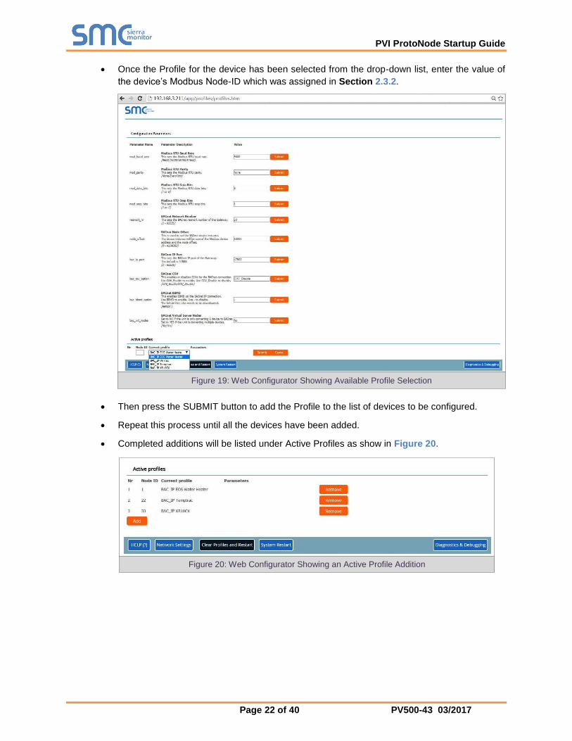
Once the Profile for the device has been selected from the drop-down list, enter the value of
the device’s Modbus Node-ID which was assigned in Section 2.3.2.
Then press the SUBMIT button to add the Profile to the list of devices to be configured.
Repeat this process until all the devices have been added.
Completed additions will be listed under Active Profiles as show in Figure 20.
Figure 19: Web Configurator Showing Available Profile Selection
Figure 20: Web Configurator Showing an Active Profile Addition

PVI ProtoNode Startup Guide
Page 23 of 40 PV500-43 03/2017
4.3 BACnet/IP and Modbus TCP/IP: Setting IP Address for Field Network
After setting a local PC to the same subnet as the ProtoNode (Section 4.1), open a web browser
on the PC and enter the IP Address of the ProtoNode; the default address is 192.168.1.24.
The Web Configurator is displayed as the landing page. (Figure 21)
To access the Web GUI, click on the “Diagnostics & Debugging” button in the bottom right
side of the page.
Figure 21: Web Configurator Screen

PVI ProtoNode Startup Guide
Page 24 of 40 PV500-43 03/2017
From the Web GUI landing page, click on “Setup” to expand the navigation tree and then select
“Network Settings” to access the IP Settings menu. (Figure 22)
Modify the IP Address (N1 IP Address field) of the ProtoNode Ethernet port.
If necessary, change the Netmask (N1 Netmask field).
Type in a new Subnet Mask.
If necessary, change the IP Gateway (Default Gateway field).
Type in a new IP Gateway.
NOTE: If the ProtoNode is connected to a router, the IP Gateway of the ProtoNode should be set to the IP Address of that router.
Reset ProtoNode.
Unplug Ethernet cable from PC and connect it to the network hub or router.
Record the IP Address assigned to the ProtoNode for future reference.
Figure 22: Changing IP Address via Web GUI

PVI ProtoNode Startup Guide
Page 25 of 40 PV500-43 03/2017
5 BACNET MS/TP AND BACNET/IP: SETTING NODE_OFFSET TO ASSIGN
SPECIFIC DEVICE INSTANCES
After setting a local PC to be on the same subnet as the ProtoNode (Section 4.1), open a web
browser on the PC and enter the IP Address of the ProtoNode; the default address is
192.168.1.24.
If the IP Address of the ProtoNode has been changed by previous configuration, the assigned IP
Address must be gathered from the network administrator.
The Web Configurator is displayed as the landing page. (Figure 21)
Node_Offset field will be presented displaying the current value (default = 50,000).
Change the value of Node_Offset to establish the desired Device Instance values, and click
SUBMIT.
o Given that: Device Instance = Node_Offset + Modbus Node_ID
o Then: Node_Offset (required) = Device Instance (desired) – Modbus Node_ID
For example, if the desired Device Instance for the 1st device is 1,001:
o Device 1 has a Modbus Node-ID of 1
o Device 2 has a Modbus Node-ID of 22
o Device 3 has a Modbus Node-ID of 33
o Node_Offset (required) = 1,001 – (Modbus Node_ID) = 1,001 – 1 = 1,000
NOTE: The Node_Offset value will be applied to all devices.
o Device 1 Instance will then be = 1,000 + Modbus Node_ID = 1,000 + 1 = 1,001
o Device 2 Instance will then be = 1,000 + Modbus Node_ID = 1,000 + 22 = 1,022
o Device 3 Instance will then be = 1,000 + Modbus Node_ID = 1,000 + 33 = 1,033
Figure 23: Web Configurator screen

PVI ProtoNode Startup Guide
Page 26 of 40 PV500-43 03/2017
6 HOW TO START THE INSTALLATION OVER: CLEARING PROFILES
After setting a local PC to the same subnet as the ProtoNode (Section 4.1), open a web browser
on the PC and enter the IP Address of the ProtoNode; the default address is 192.168.1.24.
If the IP Address of the ProtoNode has been changed by previous configuration, the assigned IP
Address must be gathered from the network administrator.
The Web Configurator is displayed as the landing page.
At the bottom-left of the page, click the “Clear Profiles and Restart” button.
Once restart is complete, all past profiles discovered and/or added via Web configurator are
deleted. The unit can now be reinstalled.

PVI ProtoNode Startup Guide
Page 27 of 40 PV500-43 03/2017
7 LONWORKS (FPC-N35): COMMISSIONING PROTONODE ON A LONWORKS NETWORK
Commissioning may only be performed by the LonWorks administrator.
7.1 Commissioning ProtoNode FPC-N35 on a LonWorks Network
The User will be prompted by the LonWorks Administrator to hit the Service Pin on the ProtoNode
FPC-N35 at the correct step of the Commissioning process which is different for each LonWorks
Network Management Tool.
If an XIF file is required, see steps in Section 7.1.1 to generate XIF.
7.1.1 Instructions to Download XIF File from ProtoNode FPC-N35 Using Browser
Connect a CAT5 Ethernet cable (Straight through or Cross-Over) between the PC and
ProtoNode.
The Default IP Address of ProtoNode is 192.168.1.24, Subnet Mask is 255.255.255.0. If the
PC and ProtoNode are on different IP Networks, assign a static IP Address to the PC on the
192.168.1.xxx network.
For Windows XP:
Go to > >
Right-click on Local Area Connection > Properties
Highlight >
For Windows 7:
Go to > >
> >
Right-click on Local Area Connection > Properties
Highlight >
For Windows XP and Windows 7, use the following IP Address:
Figure 24: LonWorks Service Pin Location

PVI ProtoNode Startup Guide
Page 28 of 40 PV500-43 03/2017
Click twice.
Open a web browser and go to the following address: IP Address of ProtoCessor/fserver.xif
Example: 192.168.1.24/fserver.xif
If the web browser prompts to save the file, save the file onto the PC. If the web browser
displays the xif file as a web page, save the file onto the local PC as “fserver.xif”.
Figure 25: Sample of Fserver.XIF File Generated

PVI ProtoNode Startup Guide
Page 29 of 40 PV500-43 03/2017
8 CAS BACNET EXPLORER FOR VALIDATING PROTONODE IN THE FIELD
ProtoCessor has arranged a complementary 2 week fully functional copy of CAS BACnet Explorer
(through Chipkin Automation) that can be used to validate BACnet MS/TP and/or BACnet/IP
communications of ProtoNode in the field without having to have the BMS Integrator on site. A serial
or USB to RS-485 converter is needed to test BACnet MS/TP.
8.1 Downloading the CAS Explorer and Requesting an Activation Key
To request the complementary BACnet CAS key, go to
http://app.chipkin.com/activation/twoweek/ and fill in all the information. Enter Vendor Code
“PVI2BACnet”. Once completed, the email address that was submitted will be registered.
Go to the following web site, download and install the CAS BACnet Explorer to the local PC:
http://www.chipkin.com/technical-resources/cas-bacnet-explorer/
Open CAS BACnet Explorer; in the CAS Activation form, enter the email address that was
registered and click on “Request a key”. The CAS key will then be emailed to the registered
address. Cut/paste key from email into the Product key field and click “Activate”.
Figure 26: Downloading the CAS Explorer
Figure 27: Requesting CAS Activation Key

PVI ProtoNode Startup Guide
Page 30 of 40 PV500-43 03/2017
8.2 CAS BACnet Setup
These are the instructions to set CAS Explorer up for the first time on BACnet MS/ST and
BACnet/IP.
8.2.1 CAS BACnet MS/TP Setup
Using the serial or USB to RS-485 converter, connect it to the local PC and the 3 Pin BACnet
MS/TP connector on ProtoNode FPC-N34.
In CAS Explorer, do the following:
o Click on settings
o Check the BACnet MS/TP box and uncheck the BACnet/IP and BACnet Ethernet
boxes
o Set the BACnet MS/TP MAC address to 0
o Set the BACnet MS/TP Baud Rate to 38400
o Click Ok
o On the bottom right-hand corner, make sure that the BACnet MS/TP box is green
o Click on discover
o Check all 4 boxes
o Click Send
8.2.2 CAS BACnet BACnet/IP Setup
See Section 7.1 to set the IP Address and subnet of the PC that will be running the CAS
Explorer.
Connect a straight through or cross Ethernet cable from the PC to ProtoNode.
In CAS Explorer, do the following:
o Click on settings
o Check the BACnet/IP box and uncheck the BACnet MS/TP and BACnet Ethernet
boxes
o In the “Select a Network Device” box, select the network card of the PC
o Click Ok
o On the bottom right-hand corner, make sure that the BACnet/IP box is green
o Click on discover
o Check all 4 boxes
o Click Send

PVI ProtoNode Startup Guide
Page 31 of 40 PV500-43 03/2017
Appendix A. Troubleshooting
Lost or Incorrect IP Address
Ensure that FieldServer Toolbox is loaded onto the local PC. If not, download FieldServer-
Toolbox.zip on the Sierra Monitor webpage, under Customer Care-Resource Center, Software
Downloads:
http://www.sierramonitor.com/customer-care/resource-center?filters=software-downloads
Extract the executable file and complete the installation.
Disable any wireless Ethernet adapters on the PC/Laptop.
Disable firewall and virus protection software if possible.
Connect a standard CAT5 Ethernet cable between the PC and ProtoNode.
Double click on the FS Toolbox Utility.
Check IP Addresses from the Device listings.
Correct IP Address(es) by right clicking the settings icon and changing the IP Address.
Ethernet Port
Figure 28: Ethernet Port Location

PVI ProtoNode Startup Guide
Page 32 of 40 PV500-43 03/2017
Viewing Diagnostic information
Type the IP Address of the ProtoNode into the web browser or use the FieldServer Toolbox to
connect to the ProtoNode.
Click on Diagnostics and Debugging Button, then click on view, and then on connections.
If there are any errors showing on the Connection page, please refer to 0 for the relevant wiring
and settings.
Figure 29: Error messages screen

PVI ProtoNode Startup Guide
Page 33 of 40 PV500-43 03/2017
Check Wiring and Settings
No COMS on Modbus RTU side. If Tx/Rx are not flashing rapidly then there is a COM issue on
the Modbus side. To fix, check the following:
o Visual observations of LEDs on ProtoNode (Appendix A.5)
o Check baud rate, parity, data bits, stop bits
o Check Modbus device address
o Verify wiring
o Verify all the Modbus RTU devices were discovered in Web Configurator (Section 0)
No COMS on Modbus TCP/IP side. To fix, check the following:
o Visual observations of LEDs on ProtoNode (Appendix A.5)
o Check Modbus device address
o Verify wiring
o Verify all the Modbus TCP/IP devices were discovered in Web Configurator (Section 0)
Field COM problems:
o Visual observations of LEDs on ProtoNode (Appendix A.5)
o Visual dipswitch settings (using correct baud rate and device instance)
o Verify IP Address setting
o Verify wiring
If the problem still exists, a Diagnostic Capture needs to be taken and sent to Sierra Monitor
Corporation. (Appendix A.4)
Take Diagnostic Capture With the FieldServer Utilities
Once the Diagnostic Capture is complete, email it to [email protected]. The
Diagnostic Capture will allow us to rapidly diagnose the problem.
Ensure that FieldServer Toolbox is Loaded on the PC that is currently being used, or download
FieldServer-Toolbox.zip on the Sierra Monitor webpage, under Customer Care: Resource Center,
Software Downloads:
http://www.sierramonitor.com/customer-care/resource-center?filters=software-downloads
Extract the executable file and complete the installation.
Disable any wireless Ethernet adapters on the PC/Laptop.
Disable firewall and virus protection software if possible.
Ethernet Port
Figure 30: Ethernet Port Location

PVI ProtoNode Startup Guide
Page 34 of 40 PV500-43 03/2017
Connect a standard CAT5 Ethernet cable between the PC and ProtoNode.
Double click on the FS Toolbox Utility.
Step 1: Take a Log
o Click on the diagnose icon of the desired device.
o Select full Diagnostic.
o If desired, the default capture period can be changed.
PVI ProtoNode Startup Guide
Page 35 of 40 PV500-43 03/2017
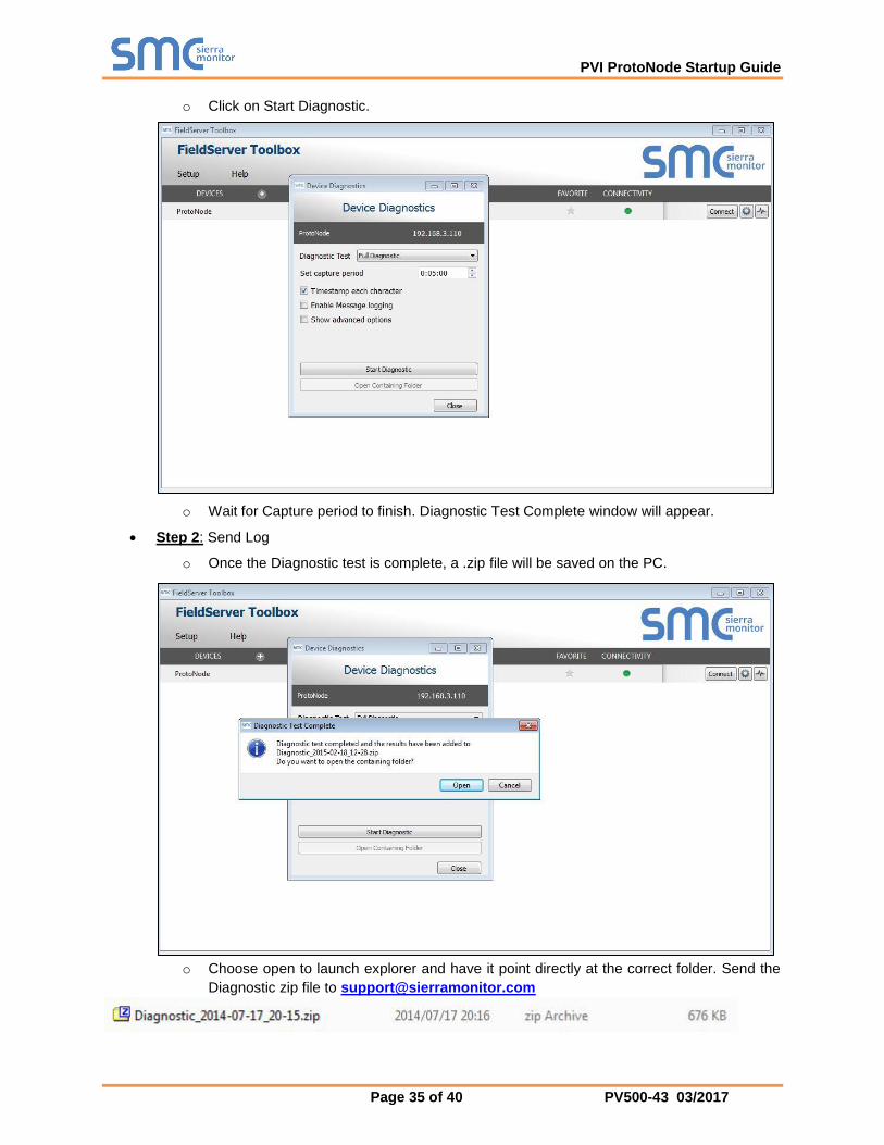
o Click on Start Diagnostic.
o Wait for Capture period to finish. Diagnostic Test Complete window will appear.
Step 2: Send Log
o Once the Diagnostic test is complete, a .zip file will be saved on the PC.
o Choose open to launch explorer and have it point directly at the correct folder. Send the
Diagnostic zip file to [email protected]

PVI ProtoNode Startup Guide
Page 36 of 40 PV500-43 03/2017
BACnet: Setting Network_Number for more than one ProtoNode on Subnet
For both BACnet MS/TP and BACnet/IP, if more than one ProtoNode is connected to the same subnet,
they must be assigned unique Network_Number values.
On the main Web Configuration screen, update the Network Number with the “network_nr” field and
click submit. The default value is 50.
Figure 31: Web Configurator – Setting Network Number for BACnet

PVI ProtoNode Startup Guide
Page 37 of 40 PV500-43 03/2017
LED Diagnostics for Communications Between ProtoNode and Devices
Please see the diagram below for ProtoNode FPC-N34 and FPC-N35 LED Locations.
Tag Description
SPL
The SPL LED will light if the ProtoNode is not getting a response from one or more of the configured devices.
For FPC-N35, the LED will also light until ProtoNode is Commissioned on the LonWorks network.
RUN The RUN LED will start flashing 20 seconds after power indicating normal operation.
ERR
The SYS ERR LED will go on solid 15 seconds after power up. It will turn off after 5 seconds. A steady red light will indicate there is a system error on ProtoNode. If this occurs, immediately report the related “system error” shown in the error screen of the GUI interface to Sierra Monitor Corporation for evaluation.
RX The RX LED will flash when a message is received on the host port.
TX The TX LED will flash when a message is sent on the host port.
PWR This is the power light and should show steady green at all times when ProtoNode is powered.
Passwords
Access to the ProtoNode can be restricted by enabling a password. There are 2 access levels defined
by 2 account names: Admin and User.
The Admin account has unrestricted access to the ProtoNode.
The User account can view any ProtoNode information, but cannot make any changes or
restart the ProtoNode.
The password needs to be a minimum of eight characters and is case sensitive.
If the password is lost, click cancel on the password authentication popup window, and e-mail the
Password recovery token to [email protected] to receive a temporary password from the
Sierra Monitor support team. Access the ProtoNode to set a new password.
Diagnostic LEDs
Figure 32: Diagnostic LEDs

PVI ProtoNode Startup Guide
Page 38 of 40 PV500-43 03/2017
Appendix B. Vendor Information - PVI
OnTrac Modbus TCP/IP Mappings to BACnet and LonWorks
OnTrac Interface Guide (PV7069-O-…PDF) contains information on wiring connections to the OnTrac and from the OnTrac to the boilers. Points List is also contained in this interface guide.
TempTrac Modbus RTU Mappings to BACnet and LonWorks
TempTrac Interface Guide (PV7069-T-…PDF) contains information on wiring connection to the TempTrac and specific applications and products the TempTrac may be installed with. TempTrac Points List is also contained in the interface guide.
XR10CX Modbus RTU Mappings to BACnet and LonWorks
XR10CX Interface Guide (PV7069-X-…PDF) contain information on wiring connection to the XR10CX and specific application and products the XR10CX may be installed with. XR10CX Points List is also contained in the interface guide.
EOS Water Heater Modbus RTU Mappings to BACnet and LonWorks
Reference the EOS Interface Guide (PV7069-E-…PDF) for interface guidance on the BTCII EOS wiring connections and specific applications. The EOS Points List is also contained in this document.

PVI ProtoNode Startup Guide
Page 39 of 40 PV500-43 03/2017
Appendix C. “A” Bank DIP Switch Settings
Address A0
1
A1
2
A2
4
A3
8
A4
16
A5
32
A6
64
A7
128
1 On Off Off Off Off Off Off Off
2 Off On Off Off Off Off Off Off
3 On On Off Off Off Off Off Off
4 Off Off On Off Off Off Off Off
5 On Off On Off Off Off Off Off
6 Off On On Off Off Off Off Off
7 On On On Off Off Off Off Off
8 Off Off Off On Off Off Off Off
9 On Off Off On Off Off Off Off
10 Off On Off On Off Off Off Off
11 On On Off On Off Off Off Off
12 Off Off On On Off Off Off Off
13 On Off On On Off Off Off Off
… … … … … … … … …
245 On Off On Off On On On On
246 Off On On Off On On On On
247 On On On Off On On On On
248 Off Off Off On On On On On
249 On Off Off On On On On On
250 Off On Off On On On On On
251 On On Off On On On On On
252 Off Off On On On On On On
253 On Off On On On On On On
254 Off On On On On On On On
255 On On On On On On On On
Address is made by using binary weighted switch settings. A0 = 1, A1=2, A2=4, A3=8, A4=16, A5=32, A6=64, A7=128. Sum of ON switches = address. For BACNET MSTP valid address range is 1-127 For MODBUS RTU valid address range is 1-247

PVI ProtoNode Startup Guide
Page 40 of 40 PV500-43 03/2017
Appendix D. Reference
Specifications
ProtoNode FPC-N34 ProtoNode FPC-N35
Electrical Connections
One 6-pin Phoenix connector with: RS-485 port (+ / - / gnd) Power port (+ / - / Frame-gnd)
One 3-pin Phoenix connector with: RS-485 port (+ / - / gnd)
One Ethernet 10/100 BaseT port
One 6-pin Phoenix connector with: RS-485 port (+ / - / gnd) Power port (+ / - / Frame-gnd)
One Ethernet 10/100 BaseT port
One FTT-10 LonWorks port
Approvals:
CE Certified; TUV approved to UL 916, EN 60950-1,
EN 50491-3 and CSA C22-2 standards; FCC Class A Part 15;
DNP3 Conformance Tested; RoHS Compliant; CSA 205 Approved
BTL Marked LonMark Certified
Power Requirements Multi-mode power adapter: 9-30VDC or 12 - 24VAC
Physical Dimensions 11.5 cm L x 8.3 cm W x 4.1 cm H (4.5 x 3.2 x 1.6 in.)
Weight 0.2 kg (0.4 lbs)
Operating Temperature -40°C to 75°C (-40°F to167°F)
Surge Suppression EN61000-4-2 ESD EN61000-4-3 EMC EN61000-4-4 EFT
Humidity 5 - 90% RH (non-condensing)
(Specifications subject to change without notice) Figure 33: Specifications
Appendix D.1.1. Compliance with UL Regulations
For UL compliance, the following instructions must be met when operating ProtoNode.
The units shall be powered by listed LPS or Class 2 power supply suited to the expected operating temperature range.
The interconnecting power connector and power cable shall: o Comply with local electrical code
o Be suited to the expected operating temperature range
o Meet the current and voltage rating for ProtoNode/Net
Furthermore, the interconnecting power cable shall: o Be of length not exceeding 3.05m (118.3”)
o Be constructed of materials rated VW-1, FT-1 or better
If the unit is to be installed in an operating environment with a temperature above 65 °C, it should be installed in a Restricted Access Area requiring a key or a special tool to gain access.
This device must not be connected to a LAN segment with outdoor wiring.