thank you for purchasing the protonode for eaton-cooper ... · eaton-cooper protonode startup guide...
TRANSCRIPT

Document Revision: 1.H Auto Discovery
Template Revision: 53
ProtoNode FPC-N34 and ProtoNode FPC-N35 Startup Guide
For Interfacing Eaton-Cooper Products: Greengate and iLUMIN
To Building Automation Systems: BACnet MS/TP, BACnet/IP, Modbus TCP/IP, Modbus RTU
and LonWorks
APPLICABILITY & EFFECTIVITY
Explains ProtoNode FPC-N34 and FPC-N35 hardware and how to install it.
The instructions are effective for the above as of February 2016.

Eaton-Cooper ProtoNode Startup Guide
Page 2 of 60
Technical Support:
Thank you for purchasing the ProtoNode for Eaton-Cooper.
Please call Eaton-Cooper for Technical support of the ProtoNode product.
SMC does not provide direct support. If Eaton-Cooper needs to escalate the concern, they will contact
Sierra Monitor Corporation for assistance.
Support Contact Information:
Eaton Lighting Systems
203 Cooper Circle
Peachtree City, GA 30269
Eaton-Cooper Service:
800-553-3879
Email: [email protected]
Website: www.eaton.com/lightingsystems

Eaton-Cooper ProtoNode Startup Guide
Page 3 of 60
A Quick Start Guide
1. Record the information about the unit. (Section 2.1)
2. Set the Device COM setting that will be connected to ProtoNode. (Section 2.3.2)
3. Connect ProtoNode FPC-N34’s 3 pin RS-485 port to the Field Protocol cabling (Section 3.2),
or connect ProtoNode FPC-N35’s 2 pin LonWorks port to the Field Protocol cabling. (Section 3.3)
4. Connect Power to ProtoNode’s 6 pin connector. (Section 3.4)
5. Connect a PC to the ProtoNode via Ethernet cable and change the IP Address of the PC to the same
subnet as the ProtoNode. (Section 4.1)
6. Set the IP Address of the ProtoNode to the subnet of the intended Network and reset IP details of
the PC. (Section 4.3)
7. Set the BACnet settings via the Web Configurator GUI. (Section 4.3.1)
8. Use the Web Configurator Discovery function to configure the ProtoNode and to find any light panels
connected to the Device. (Section 4.3.1.2)
9. LonWorks (FPC-N35): The ProtoNode must be commissioned on the LonWorks Network. This
needs to be done by the LonWorks administrator using a LonWorks Commissioning tool. (Section
6)

Eaton-Cooper ProtoNode Startup Guide
Page 4 of 60
Certifications
BTL MARK – BACNET TESTING LABORATORY
LONMARK CERTIFICATION
The BTL Mark on ProtoNode is a symbol that indicates that a product has
passed a series of rigorous tests conducted by an independent laboratory
which verifies that the product correctly implements the BACnet features
claimed in the listing. The mark is a symbol of a high-quality BACnet product.
Go to http://www.BACnetInternational.net/btl/ for more information about the
BACnet Testing Laboratory. Click here for BACnet PIC Statement
LonMark International is the recognized authority for certification, education,
and promotion of interoperability standards for the benefit of manufacturers,
integrators and end users. LonMark International has developed extensive
product certification standards and tests to provide the integrator and user with
confidence that products from multiple manufacturers utilizing LonMark
devices work together. FieldServer Technologies has more LonMark Certified
gateways than any other gateway manufacturer, including the ProtoCessor,
ProtoCarrier and ProtoNode for OEM applications and the full featured,
configurable gateways.

Eaton-Cooper ProtoNode Startup Guide
Page 5 of 60
TABLE OF CONTENTS
1 Introduction .......................................................................................................................................... 6 1.1 ProtoNode Gateway ....................................................................................................................... 7
2 BACnet/LonWorks Setup for ProtoCessor ProtoNode FPC-N34/FPC-N35 .................................... 8 2.1 Record Identification Data .............................................................................................................. 8 2.2 Point Count Capacity and Registers per Device ............................................................................ 8 2.3 Configuring Device IP Communications ......................................................................................... 9
2.3.1 Set Greengate or iLUMIN IP Address Connected to the ProtoNode ........................................ 9 2.3.2 Configure Device IP Address settings ...................................................................................... 9
3 Interfacing ProtoNode to Devices .................................................................................................... 10 3.1 ProtoNode FPC-N34 and FPC-N35 Showing Connection Ports .................................................. 10 3.2 BACnet MS/TP (FPC-N34): Wiring Field Port to RS-485 BMS Network ...................................... 11 3.3 LonWorks (FPC-N35): Wiring Field Port to LonWorks Network ................................................... 11 3.4 Power-Up ProtoNode.................................................................................................................... 12
4 Configure the Protonode via Web Configurator GUI ..................................................................... 13 4.1 Connect the PC to ProtoNode via the Ethernet Port .................................................................... 13 4.2 Connecting to the ProtoNode Web Configurator GUI ..................................................... 14 4.3 Set BACnet/IP and Modbus TCP/IP Address of ProtoNode to Same Switch/Router of the Device ........................................................................................................................................ 15
4.3.1 Select Network Protocol ................................................................................................ 16 4.3.2 Configure the Device on the ProtoNode and Automatically Discover Light Panels Connected to the Device ................................................................................................. 20
5 BACnet MS/TP and BACnet/IP: Setting Node_Offset to Assign Specific Device Instances ..... 25
6 LonWorks (FPC-N35): Commissioning ProtoNode on a lonworks Network ............................... 26 6.1 Commissioning ProtoNode FPC-N35 on a LonWorks Network ................................................... 26
6.1.1 Instructions to Download XIF File from ProtoNode FPC-N35 Using Browser ........................ 26
7 CAS BACnet Explorer for Validating ProtoNode in the Field ........................................................ 28 7.1 Downloading the CAS Explorer and Requesting an Activation Key ............................................. 28 7.2 CAS BACnet Setup....................................................................................................................... 29
7.2.1 CAS BACnet MS/TP Setup ..................................................................................................... 29 7.2.2 CAS BACnet BACnet/IP Setup ............................................................................................... 29
Appendix A. Troubleshooting .................................................................................................................. 30 Appendix A.1. Lost or Incorrect IP Address ............................................................................................ 30 Appendix A.2. Viewing Diagnostic information ........................................................................................ 31 Appendix A.3. Check Wiring and Settings............................................................................................... 32 Appendix A.4. Take Diagnostic Capture With the FieldServer Utilities ................................................... 32 Appendix A.5. BACnet: Setting Network_Number for more than one ProtoNode on Subnet ................. 35 Appendix A.6. LED Diagnostics for Communications Between ProtoNode and Devices ....................... 36 Appendix A.7. Passwords ....................................................................................................................... 36
Appendix B. Vendor Information – Eaton-Cooper ................................................................................. 37 Appendix B.1. 3264640000 Greengate Mappings to BACnet, Modbus and LonWorks ......................... 37 Appendix B.2. 4864643204 Greengate Mappings to BACnet, Modbus and LonWorks ......................... 40 Appendix B.3. 808640000 Greengate Mappings to BACnet, Modbus and LonWorks ........................... 45 Appendix B.4. 344640003 Greengate Mappings to BACnet, Modbus and LonWorks ........................... 46 Appendix B.5. 1664643204 Greengate Mappings to BACnet, Modbus and LonWorks ......................... 49 Appendix B.6. 6464643200 Greengate Mappings to BACnet, Modbus and LonWorks ......................... 53 Appendix B.7. Scene iLUMIN Mappings to BACnet, Modbus and LonWorks ........................................ 58 Appendix B.8. Channel iLUMIN Mappings to BACnet, Modbus and LonWorks ..................................... 58
Appendix C. Reference ............................................................................................................................. 59 Appendix C.1. Specifications ................................................................................................................... 59
Appendix C.1.1. Compliance with UL Regulations ........................................................................... 59

Eaton-Cooper ProtoNode Startup Guide
Page 6 of 60
Appendix D. Limited 2 Year Warranty ..................................................................................................... 60
LIST OF FIGURES
Figure 1: ProtoCessor Part Numbers ............................................................................................................ 8 Figure 2: Supported Point Count Capacity ................................................................................................... 8 Figure 3: Greengate Point Count per Device ................................................................................................ 8 Figure 4: iLUMIN Point Count per Device ..................................................................................................... 8 Figure 5: ProtoNode BACnet FPC-N34 (upper) and ProtoNode FPC-N35 (lower) .................................... 10 Figure 6: Connection from ProtoNode to RS-485 Field Network ................................................................ 11 Figure 7: RS-485 BMS Network EOL Switch .............................................................................................. 11 Figure 8: LonWorks Terminal ...................................................................................................................... 11 Figure 9: Required Current Draw for the ProtoNode .................................................................................. 12 Figure 10: Power Connections .................................................................................................................... 12 Figure 11: Select System Page .................................................................................................................. 14 Figure 12: Web Configurator GUI ............................................................................................................... 14 Figure 13: IP Address Settings via Web GUI .............................................................................................. 15 Figure 14: BMS settings Window ................................................................................................................ 16 Figure 15: BACnet/IP Settings Window ...................................................................................................... 17 Figure 16: BACnet MS/TP Settings Window............................................................................................... 18 Figure 17: Modbus TC/IP Settings Window ................................................................................................ 19 Figure 18: Modbus RTU Settings Window .................................................................................................. 19 Figure 19: Start Discovery Fields ................................................................................................................ 20 Figure 20: Discovery Bar ............................................................................................................................. 20 Figure 21: The Discovery Tree.................................................................................................................... 21 Figure 22: View & Edit Gateway Parameters .............................................................................................. 21 Figure 23: View Light Panel Parameters .................................................................................................... 22 Figure 24: View & Edit BACnet Parameters on a Lighting Panel ............................................................... 22 Figure 25: Saving Configurations Bar ......................................................................................................... 23 Figure 26: Saved Configurations ................................................................................................................ 23 Figure 27: Clear Configuration Window ...................................................................................................... 24 Figure 28: Clearing Configurations ............................................................................................................. 24 Figure 29: Web Configurator Settings Window ........................................................................................... 25 Figure 30: LonWorks Service Pin Location ................................................................................................. 26 Figure 31: Sample of Fserver.XIF File Being Generated ............................................................................ 27 Figure 32: Downloading the CAS Explorer ................................................................................................. 28 Figure 33: Requesting CAS Activation Key ................................................................................................ 28 Figure 34: Ethernet Port Location ............................................................................................................... 30 Figure 35: Error messages screen .............................................................................................................. 31 Figure 36: Ethernet Port Location ............................................................................................................... 32 Figure 37: Web Configurator showing Network Number Setting for BACnet/IP ......................................... 35 Figure 38: Diagnostic LEDs ........................................................................................................................ 36 Figure 39: Specifications ............................................................................................................................. 59

Eaton-Cooper ProtoNode Startup Guide
Page 7 of 60
1 INTRODUCTION
1.1 ProtoNode Gateway
ProtoNode is an external, high performance Building Automation multi-protocol gateway that is
preconfigured to Auto-Discover any of the Eaton-Cooper’s products (hereafter called “device”) connected
to the ProtoNode and automatically configures them for BACnet®1MS/TP, BACnet/IP, Modbus TCP/IP or
LonWorks®2.
It is not necessary to download any configuration files to support the required applications. The
ProtoNode is pre-loaded with tested Profiles/Configurations for the supported devices.
1 BACnet is a registered trademark of ASHRAE
2 LonWorks is a registered trademark of Echelon Corporation

Eaton-Cooper ProtoNode Startup Guide
Page 8 of 60
2 BACNET/LONWORKS SETUP FOR PROTOCESSOR PROTONODE FPC-
N34/FPC-N35
2.1 Record Identif ication Data
Each ProtoNode has a unique part number located on the side or the back of the unit. This number
should be recorded, as it may be required for technical support. The numbers are as follows:
Model Part Number
ProtoNode N34 FPC-N34-1130
ProtoNode N35 FPC-N35-1131
Figure 1: ProtoCessor Part Numbers
FPC-N34 units have the following 3 ports: RS-485 + Ethernet + RS-485.
FPC-N35 units have the following 3 ports: LonWorks + Ethernet + RS-485.
2.2 Point Count Capacity and Registers per Device
The total number of points presented by all of the devices attached to the ProtoNode cannot
exceed:
Part number Total Point Capacity
FPC-N34-1130 10,000
FPC-N35-1131 4,096
Figure 2: Supported Point Count Capacity
Greengate Devices Point Count Per Device
3264640000 161
4864643204 213
808640000 81
344640003 115
1664643204 181
6464643200 225
Figure 3: Greengate Point Count per Device
iLUMIN Devices Point Count Per Device
Scene 2
Channel 2
Figure 4: iLUMIN Point Count per Device

Eaton-Cooper ProtoNode Startup Guide
Page 9 of 60
2.3 Configuring Device IP Communications
2.3.1 Set Greengate or iLUMIN IP Address Connected to the ProtoNode
The Greengate or iLUMIN device needs to be on the same IP subnet as the ProtoNode and the
configuration PC.
2.3.2 Configure Device IP Address settings
Record the following to start the setup:
o IP Address
o IP port
o Panel Address
o Number of Panels
Note: This information is required for Section 4.

Eaton-Cooper ProtoNode Startup Guide
Page 10 of 60
3 INTERFACING PROTONODE TO DEVICES
3.1 ProtoNode FPC-N34 and FPC-N35 Showing Connection Ports
Figure 5: ProtoNode BACnet FPC-N34 (upper) and ProtoNode FPC-N35 (lower)

Eaton-Cooper ProtoNode Startup Guide
Page 11 of 60
3.2 BACnet MS/TP (FPC-N34): Wiring Field Port to RS-485 BMS Network
Connect the BACnet MS/TP RS-485 network wires to the 3-pin RS-485 connector on
ProtoNode FPC-N34 as shown below in Figure 6.
o The RS-485 GND (Pin 3) is not typically connected.
See Section 5 for information on connecting to BACnet/IP network.
If the ProtoNode is the last device on the BACnet MS/TP, then the End-Of-Line
Termination Switch needs to be enabled. (Figure 7)
o The default setting from the factory is OFF (switch position = right side).
o To enable the EOL Termination, turn the EOL switch ON (switch position = left
side).
3.3 LonWorks (FPC-N35): Wiring Field Port to LonWorks Network
Connect ProtoNode to the field network with the LonWorks terminal using a twisted pair non-
shielded cable. LonWorks has no polarity.
BMS RS-
485 Wiring
ProtoNode
Pin #
Pin
Assignment
RS-485 + Pin 1 RS-485 +
RS-485 - Pin 2 RS-485 -
- Pin 3 RS-485 GND
Figure 8: LonWorks Terminal
End-of-Line Switch
Figure 7: RS-485 BMS Network EOL Switch
G
-
+ Figure 6: Connection from ProtoNode to RS-485 Field Network

Eaton-Cooper ProtoNode Startup Guide
Page 12 of 60
3.4 Power-Up ProtoNode
Apply power to ProtoNode as show below in Figure 10. Ensure that the power supply used
complies with the specifications provided in Appendix C.1.
ProtoNode accepts either 9-30VDC or 12-24 VAC on pins 4 and 5.
Frame GND should be connected.
Power Requirement for ProtoNode External Gateway
Current Draw Type
ProtoNode Family 12VDC/VAC 24VDC/VAC 30VDC
FPC – N34 (Typical) 170mA 100mA 80mA
FPC – N34 (Maximum) 240mA 140mA 100mA
FPC – N35 (Typical) 210mA 130mA 90mA
FPC – N35 (Maximum) 250mA 170mA 110mA
Note: These values are ‘nominal’ and a safety margin should be added to the power supply of the host system. A safety margin of 25% is recommended.
Figure 9: Required Current Draw for the ProtoNode
Power to
ProtoNode
ProtoNode
Pin #
Pin
Assignment
Power In (+) Pin 4 V +
Power In (-) Pin 5 V -
Frame Ground Pin 6 FRAME GND
Figure 10: Power Connections

Eaton-Cooper ProtoNode Startup Guide
Page 13 of 60
4 CONFIGURE THE PROTONODE VIA WEB CONFIGURATOR GUI
4.1 Connect the PC to ProtoNode via the Ethernet Port
Connect a Cat 5 Ethernet cable (Straight through or Cross-Over) between the PC and
ProtoNode.
The Default IP Address of ProtoNode is 192.168.1.24, Subnet Mask is 255.255.255.0. If the PC
and ProtoNode are on different IP Networks, assign a static IP Address to the PC on the
192.168.1.xxx network.
For Windows XP:
Go to > >
Right-click on Local Area Connection > Properties
Highlight >
For Windows 7:
Go to > >
> >
Right-click on Local Area Connection > Properties
Highlight >
For Windows XP and Windows 7, use the following IP Address:
Click twice.

Eaton-Cooper ProtoNode Startup Guide
Page 14 of 60
4.2 Connecting to the ProtoNode Web Configurator GUI
After setting the PC on the same subnet as the ProtoNode (Section 4.1), open a web browser
on the PC and enter the IP Address of the ProtoNode; the default address is 192.168.1.24.
The Configurator Web GUI will now appear when entering the device’s IP Address on the
browser.
Select the desired protocol.
The Configurator Web GUI landing page will now appear.
NOTE: If the wrong protocol was selected, click the Clear Configuration button to reset the GUI and go
back to the Select System Page.
Figure 12: Web Configurator GUI
Figure 11: Select System Page

Eaton-Cooper ProtoNode Startup Guide
Page 15 of 60
4.3 Set BACnet/IP and Modbus TCP/IP Address of ProtoNode to Same
Switch/Router of the Device
From the Web GUI’s landing page, click on “Network Settings” Tab to access the IP Settings
menu. (Figure 13)
Enter new IP Address (N1 IP Address field) of the ProtoNode Ethernet port to the same switch or router’s subnet that the device is connected.
If necessary, change the Netmask (N1 Netmask field).
Type in a new subnet mask.
If necessary, change the IP Gateway (Default Gateway field).
Type in a new IP Gateway.
Reset ProtoNode.
Connect the ProtoNode to same switch or router that the Device is connected.
Connect the PC to the same switch or router and change the IP Address of the PC to be
on the same subnet of the Device and the ProtoNode.
Record the IP Address assigned to the ProtoNode for future reference.
After setting the PC to be on the same subnet as the ProtoNode and the Device, open a web browser on the PC and enter the new IP of the ProtoNode.
Figure 13: IP Address Settings via Web GUI

Eaton-Cooper ProtoNode Startup Guide
Page 16 of 60
4.3.1 Select Network Protocol
Going back to the Discovery and Configuration tab, and press BMS Settings button to view/ Change the Building Management System (BMS) Settings.
Select BACnet/IP, BACnet MS/TP, Modbus TCP/IP, or Modbus RTU protocols.
Figure 14: BMS settings Window

Eaton-Cooper ProtoNode Startup Guide
Page 17 of 60
4.3.1.1 Set Device Instance for each lighting panel attached to the Device
The Device Instance can be set independently of the site administrator.
As an example:
A Device Instance is a BACnet Node-ID which is obtained by the network administrator.
Each lighting panel connected to the Device will have its own BACnet Device Instance.
The values allowed for a BACnet Device Instance can range from 1 to 4,194,303.
With the default BACnet Device Instance value of 50,000 the Device Instances values
generated will be within the range of 50,000 plus the incremental number of lighting panels that
are connected to the ProtoNode. The first lighting panel will therefore be 50,000.
To assign a specific Device Instance (or range); change the Device instance value to assigned
value of the first lighting panel.
The Web Configurator will be displayed as the landing page.
Figure 15: BACnet/IP Settings Window

Eaton-Cooper ProtoNode Startup Guide
Page 18 of 60
4.3.1.2 BACnet MS/TP (FPC-N34): Setting the MAC Address BACnet Network
Only 1 MAC address is set for ProtoNode regardless of how many light panels are connected to
ProtoNode.
Set the BACnet MS/TP MAC address of the ProtoNode to a value between 1 to 127 (MAC
Master Addresses); this is so that the BMS Front End can find the ProtoNode via BACnet auto
discovery.
Note: Never set a BACnet MS/TP MAC Address from 128 to 255. Addresses from 128 to
255 are Slave Addresses and can not be discovered by BMS Front Ends that support auto
discovery of BACnet MS/TP devices.
Enter the following details into the web configuration as per Figure 16 below:
Device Instance – Enter a range between 1 and 4,194,303.
Name – Enter the name of the Device.
Location – Enter the location of the lighting panel.
Device Instance Offset – Default of 50000 so that Device Instance begins at 50001.
Network Number – Leave as default unless instructed by BMS integrator.
Baud Rate – Enter a value of 9600, 19200, 38400, or 76800.
Figure 16: BACnet MS/TP Settings Window

Eaton-Cooper ProtoNode Startup Guide
Page 19 of 60
4.3.1.3 Modbus TC/IP and Modbus RTU Settings
Modbus TC/IP
Modbus RTU
Figure 17: Modbus TC/IP Settings Window
Figure 18: Modbus RTU Settings Window

Eaton-Cooper ProtoNode Startup Guide
Page 20 of 60
4.3.2 Configure the Device on the ProtoNode and Automatically Discover Light
Panels Connected to the Device
Click on the “Start Discovery” button to enter the port, network address, Panel Address and
Number of Panels for the Device.
o After entering the Device details, click on the “Start Discovery” button and the discovery
progress bar will display.
o The discovery of a Device may take a few minutes depending on the number of items it
contains.
Figure 19: Start Discovery Fields
Figure 20: Discovery Bar

Eaton-Cooper ProtoNode Startup Guide
Page 21 of 60
After the discovery process is complete, the discovery tree will immediately come up.
The items being marked as green indicate that they have not been configured for protocol conversion.
o When clicking on gateways or gateways containing light panels a tick box will check or
uncheck items for Protocol conversion.
o By clicking on a gateway the parameters will be shown and can be edited.
Figure 21: The Discovery Tree
Figure 22: View & Edit Gateway Parameters

Eaton-Cooper ProtoNode Startup Guide
Page 22 of 60
o By clicking on a light panel, parameters for that panel will be shown.
o Clicking on a light displays and allows editing of the preconfigured BACnet parameters.
Figure 23: View Light Panel Parameters
Figure 24: View & Edit BACnet Parameters on a Lighting Panel

Eaton-Cooper ProtoNode Startup Guide
Page 23 of 60
Once the items for configuration are chosen, click on the “Save Configuration” button. The save
configuration progress bar will appear. This process may take several minutes.
When this process is complete, the items on the tree will change from green to black to show
that they have been configured.
Figure 25: Saving Configurations Bar
Figure 26: Saved Configurations

Eaton-Cooper ProtoNode Startup Guide
Page 24 of 60
In order to clear a configuration, click on the “Clear Configuration” button. An additional option
to clear all other device configurations will appear.
After clicking on the Clear & Restart button the following message will appear.
After this process is complete, the ProtoNode will automatically restart.
Figure 27: Clear Configuration Window
Figure 28: Clearing Configurations

Eaton-Cooper ProtoNode Startup Guide
Page 25 of 60
5 BACNET MS/TP AND BACNET/IP: SETTING NODE_OFFSET TO ASSIGN
SPECIFIC DEVICE INSTANCES
After setting your PC to be on the same subnet as the ProtoNode (Section 4), open a web
browser on your PC and enter the IP Address of the ProtoNode; the default address is
192.168.1.24.
If the IP Address of the ProtoNode has been changed by previous configuration get the
assigned IP Address from the network administrator.
The Web Configurator will be displayed, click “BMS Settings”. (Figure 29)
Node_Offset field will be presented displaying the current value (default = 50,000).
Change the value of the Node_Offset to establish the desired Device Instance values, then
click “SUBMIT”.
o Given that: Node_Offset + Greengate Node_ID = Device Instance
o Then: Node_Offset (required) = Device Instance (desired) – Greengate Node_ID
For example:
o Device 1 has a Greengate Node-ID of 1
o Device 2 has a Greengate Node-ID of 22
o Device 3 has a Greengate Node-ID of 33
o Desired Device Instance for 1st device = 1,001
o Node_Offset (required) = 1,001 – (Greengate Node_ID) = 1,001 – 1 = 1,000
o The Node_Offset value will be applied to all devices.
o Device 1 Instance will then be = 1,000 + Greengate Node_ID = 1,000 + 1 = 1,001
o Device 2 Instance will then be = 1,000 + Greengate Node_ID = 1,000 + 22 = 1,022
o Device 3 Instance will then be = 1,000 + Greengate Node_ID = 1,000 + 33 = 1,033
Figure 29: Web Configurator Settings Window

Eaton-Cooper ProtoNode Startup Guide
Page 26 of 60
6 LONWORKS (FPC-N35): COMMISSIONING PROTONODE ON A LONWORKS NETWORK
Commissioning may only be performed by the LonWorks administrator.
6.1 Commissioning ProtoNode FPC-N35 on a LonWorks Network
The User will be prompted by the LonWorks Administrator to hit the Service Pin on the ProtoNode
FPC-N35 at the correct step of the Commissioning process which is different for each LonWorks
Network Management Tool.
If an XIF file is required, see steps in Section 6.1.1 to generate XIF.
6.1.1 Instructions to Download XIF File from ProtoNode FPC-N35 Using Browser
Connect a Cat 5 Ethernet cable (Straight through or Cross-Over) between the PC and
ProtoNode.
The Default IP Address of ProtoNode is 192.168.1.24, Subnet Mask is 255.255.255.0. If the
PC and ProtoNode are on different IP Networks, assign a static IP Address to the PC on the
192.168.1.xxx network.
For Windows XP:
Go to > >
Right-click on Local Area Connection > Properties
Highlight >
For Windows 7:
Go to > >
> >
Right-click on Local Area Connection > Properties
Highlight >
Figure 30: LonWorks Service Pin Location

Eaton-Cooper ProtoNode Startup Guide
Page 27 of 60
For Windows XP and Windows 7, select: Use the following IP Address
Click twice.
Open a web browser and go to the following address: IP Address of ProtoCessor/fserver.xif
Example: 192.168.1.24/fserver.xif.
If the web browser prompts you to save file, save the file onto the PC. If the web browser
displays the xif file as a web page, save the file on your PC as fserver.xif.
Figure 31: Sample of Fserver.XIF File Being Generated

Eaton-Cooper ProtoNode Startup Guide
Page 28 of 60
7 CAS BACNET EXPLORER FOR VALIDATING PROTONODE IN THE FIELD
ProtoCessor has arranged a complementary 2 week fully functional copy of CAS BACnet Explorer
(through Chipkin Automation) that can be used to validate BACnet MS/TP and/or BACnet/IP
communications of ProtoNode in the field without having to have the BMS Integrator on site. A
Serial or USB to RS-485 converter is needed to test BACnet MS/TP.
7.1 Downloading the CAS Explorer and Requesting an Activation Key
To request the complementary BACnet CAS key, go to
http://app.chipkin.com/activation/twoweek/ and fill in all the information. Enter Vendor Code
“Eaton2BACnet”. Once completed, the email address that was submitted will be registered.
Go to the following web site, download and install the CAS BACnet Explorer to your PC:
http://www.chipkin.com/technical-resources/cas-bacnet-explorer/
Open CAS BACnet Explorer; in the CAS Activation form, enter the email address that was
registered and click on “Request a key”. The CAS key will then be emailed to the registered
address. Cut/paste key from email into the Product key field and click “Activate”.
Figure 32: Downloading the CAS Explorer
Figure 33: Requesting CAS Activation Key

Eaton-Cooper ProtoNode Startup Guide
Page 29 of 60
7.2 CAS BACnet Setup
These are the instructions to set CAS Explorer up for the first time on BACnet MS/TP and
BACnet/IP.
7.2.1 CAS BACnet MS/TP Setup
Using the Serial or USB to RS-485 converter, connect it to your PC and the 3 Pin BACnet
MS/TP connector on ProtoNode FPC-N34.
In CAS Explorer, do the following:
o Click on settings
o Check the BACnet MS/TP box and uncheck the BACnet/IP and BACnet Ethernet
boxes
o Set the BACnet MS/TP MAC address to 0
o Set the BACnet MS/TP Baud Rate to 38400
o Click Ok
o On the bottom right-hand corner, make sure that the BACnet MS/TP box is green
o Click on discover
o Check all 4 boxes
o Click Send
7.2.2 CAS BACnet BACnet/IP Setup
See Section 4.1 to set the IP Address and subnet of the PC that will be running the CAS
Explorer.
Connect a straight through or cross Ethernet cable from the PC to ProtoNode.
In CAS Explorer, do the following:
o Click on settings
o Check the BACnet/IP box and uncheck the BACnet MS/TP and BACnet Ethernet
boxes
o In the “Select a Network Device” box, select the network card of the PC by clicking on
it
o Click Ok
o On the bottom right-hand corner, make sure that the BACnet/IP box is green
o Click on discover
o Check all 4 boxes
o Click Send

Eaton-Cooper ProtoNode Startup Guide
Page 30 of 60
Appendix A. Troubleshooting
Appendix A.1. Lost or Incorrect IP Address
Ensure that FieldServer Toolbox is Loaded on the PC that is currently being used, or download FieldServer-Toolbox.zip on the Sierra Monitor webpage, under Customer Care: Resource Center, Software Downloads: http://www.sierramonitor.com/customer-care/resource-center?filters=software-downloads
Extract the executable file and complete the installation.
Disable any wireless Ethernet adapters on the PC/Laptop.
Disable firewall and virus protection software if possible.
Connect a standard Cat 5 Ethernet cable between the PC and ProtoNode.
Double click on the FS Toolbox Utility.
Check IP Addresses from the Device listings.
Correct IP Address(es) by right clicking the settings icon and changing the IP Address.
Ethernet Port
Figure 34: Ethernet Port Location

Eaton-Cooper ProtoNode Startup Guide
Page 31 of 60
Appendix A.2. Viewing Diagnostic information
Type the IP Address of the ProtoNode into your web browser or use the FieldServer Toolbox to
connect to the ProtoNode.
Click on Diagnostics and Debugging Button, then click on view, and then on connections.
If there are any errors showing on the Connection page, please refer to Appendix A.3 for the
relevant wiring and settings.
Figure 35: Error messages screen

Eaton-Cooper ProtoNode Startup Guide
Page 32 of 60
Appendix A.3. Check Wiring and Settings
No COMS on Greengate or iLUMIN side. Check the following:
o Check Greengate or iLUMIN IP Address
o Check Ethernet Switch
o Check Ethernet LEDs
o Verify Ethernet Cable
Field COM problems:
o Visual observations of LEDs on ProtoNode. (Appendix A.6)
o Verify IP Address setting
o Verify wiring
If the problem still exists, a Diagnostic Capture needs to be taken and sent to Sierra Monitor
Corporation. (Appendix A.4)
Appendix A.4. Take Diagnostic Capture With the FieldServer Utilities
Once the Diagnostic Capture is complete, email it to [email protected]. The
Diagnostic Capture will allow us to rapidly diagnose the problem.
Ensure that FieldServer Toolbox is Loaded on the PC that is currently being used, or download
FieldServer-Toolbox.zip on the Sierra Monitor Corporation webpage, under Customer Care:
Resource Center, Software Downloads:
http://www.sierramonitor.com/customer-care/resource-center?filters=software-downloads
Extract the executable file and complete the installation.
Disable any wireless Ethernet adapters on the PC/Laptop.
Disable firewall and virus protection software if possible.
Connect a standard cat5 Ethernet cable between the PC and ProtoNode.
Double click on the FS Toolbox Utility.
Ethernet Port
Figure 36: Ethernet Port Location

Eaton-Cooper ProtoNode Startup Guide
Page 33 of 60
Step 1: Take a Log
o Click on the diagnose icon of the desired device.
o Select full Diagnostic.

Eaton-Cooper ProtoNode Startup Guide
Page 34 of 60
o If desired, the default capture period can be changed.
o Click on Start Diagnostic.
o Wait for Capture period to finish. Diagnostic Test Complete window will appear.
Step 2: Send Log
o Once the Diagnostic test is complete, a .zip file will be saved on the PC.
o Choose open to launch explorer and have it point directly at the correct folder. Send the
Diagnostic zip file to [email protected]

Eaton-Cooper ProtoNode Startup Guide
Page 35 of 60
Appendix A.5. BACnet: Setting Network_Number for more than one ProtoNode on Subnet
For both BACnet MS/TP and BACnet/IP, if more than one ProtoNode is connected to the same subnet,
they must be assigned unique Network_Number values.
On the main Web Configuration screen, update the Network Number with the “network_nr” field and click
submit. The default value is 50.
Figure 37: Web Configurator showing Network Number Setting for BACnet/IP

Eaton-Cooper ProtoNode Startup Guide
Page 36 of 60
Appendix A.6. LED Diagnostics for Communications Between ProtoNode and Devices
Please see the diagram below for ProtoNode FPC-N34 and FPC-N35 LED Locations.
Tag Description
SPL The SPL LED will light if the ProtoNode is off line. For FPC-N35, the LED will also light until ProtoNode is Commissioned on the LonWorks network.
RUN The RUN LED will start flashing 20 seconds after power indicating normal operation.
ERR
The SYS ERR LED will go on solid 15 seconds after power up. It will turn off after 5 seconds. A steady red light will indicate there is a system error on ProtoNode. If this occurs, immediately report the related “system error” shown in the error screen of the GUI interface to FieldServer Technologies for evaluation.
RX Not Used.
TX Not Used.
PWR This is the power light and should show steady green at all times when ProtoNode is powered.
Appendix A.7. Passwords
Access to the ProtoNode can be restricted by enabling a password. There are 2 access levels defined by
2 account names: Admin and User.
The Admin account has unrestricted access to the ProtoNode.
The User account can view any ProtoNode information, but cannot make any changes or
restart the ProtoNode.
The password needs to be a minimum of eight characters and is case sensitive.
If you forgot your password, click cancel on the password authentication popup window, and e-mail the Password recovery token to [email protected] to receive a temporary password from the Sierra Monitor support team. You can now access the ProtoNode to set a new password.
Diagnostic LEDs
Figure 38: Diagnostic LEDs

Eaton-Cooper ProtoNode Startup Guide
Page 37 of 60
Appendix B. Vendor Information – Eaton-Cooper
Appendix B.1. 3264640000 Greengate Mappings to BACnet, Modbus and LonWorks
Point Name
BACnet
Object
Type
BACnet
Object
ID
Modbus
Register Lon Name Lon SNVT
Reset BV 1001 201 nviXXX_Reset SNVT_switch
Relay01 BV 1 1 nvi/nvoXXX_Relay001 SNVT_switch
Relay02 BV 2 2 nvi/nvoXXX_Relay002 SNVT_switch
Relay03 BV 3 3 nvi/nvoXXX_Relay003 SNVT_switch
Relay04 BV 4 4 nvi/nvoXXX_Relay004 SNVT_switch
Relay05 BV 5 5 nvi/nvoXXX_Relay005 SNVT_switch
Relay06 BV 6 6 nvi/nvoXXX_Relay006 SNVT_switch
Relay07 BV 7 7 nvi/nvoXXX_Relay007 SNVT_switch
Relay08 BV 8 8 nvi/nvoXXX_Relay008 SNVT_switch
Relay09 BV 9 9 nvi/nvoXXX_Relay009 SNVT_switch
Relay010 BV 10 10 nvi/nvoXXX_Relay010 SNVT_switch
Relay011 BV 11 11 nvi/nvoXXX_Relay011 SNVT_switch
Relay012 BV 12 12 nvi/nvoXXX_Relay012 SNVT_switch
Relay013 BV 13 13 nvi/nvoXXX_Relay013 SNVT_switch
Relay014 BV 14 14 nvi/nvoXXX_Relay014 SNVT_switch
Relay015 BV 15 15 nvi/nvoXXX_Relay015 SNVT_switch
Relay016 BV 16 16 nvi/nvoXXX_Relay016 SNVT_switch
Relay017 BV 17 17 nvi/nvoXXX_Relay017 SNVT_switch
Relay018 BV 18 18 nvi/nvoXXX_Relay018 SNVT_switch
Relay019 BV 19 19 nvi/nvoXXX_Relay019 SNVT_switch
Relay020 BV 20 20 nvi/nvoXXX_Relay020 SNVT_switch
Relay021 BV 21 21 nvi/nvoXXX_Relay021 SNVT_switch
Relay022 BV 22 22 nvi/nvoXXX_Relay022 SNVT_switch
Relay023 BV 23 23 nvi/nvoXXX_Relay023 SNVT_switch
Relay024 BV 24 24 nvi/nvoXXX_Relay024 SNVT_switch
Relay025 BV 25 25 nvi/nvoXXX_Relay025 SNVT_switch
Relay026 BV 26 26 nvi/nvoXXX_Relay026 SNVT_switch
Relay027 BV 27 27 nvi/nvoXXX_Relay027 SNVT_switch
Relay028 BV 28 28 nvi/nvoXXX_Relay028 SNVT_switch
Relay029 BV 29 29 nvi/nvoXXX_Relay029 SNVT_switch
Relay030 BV 30 30 nvi/nvoXXX_Relay030 SNVT_switch
Relay031 BV 31 31 nvi/nvoXXX_Relay031 SNVT_switch
Relay032 BV 32 32 nvi/nvoXXX_Relay032 SNVT_switch
Remote01 BV 101 101 nvi/nvoXXX_Remote001 SNVT_switch
Remote02 BV 102 102 nvi/nvoXXX_Remote002 SNVT_switch
Remote03 BV 103 103 nvi/nvoXXX_Remote003 SNVT_switch
Remote04 BV 104 104 nvi/nvoXXX_Remote004 SNVT_switch
Remote05 BV 105 105 nvi/nvoXXX_Remote005 SNVT_switch
Remote06 BV 106 106 nvi/nvoXXX_Remote006 SNVT_switch
Remote07 BV 107 107 nvi/nvoXXX_Remote007 SNVT_switch
Remote08 BV 108 108 nvi/nvoXXX_Remote008 SNVT_switch

Eaton-Cooper ProtoNode Startup Guide
Page 38 of 60
Remote09 BV 109 109 nvi/nvoXXX_Remote009 SNVT_switch
Remote010 BV 110 110 nvi/nvoXXX_Remote010 SNVT_switch
Remote011 BV 111 111 nvi/nvoXXX_Remote011 SNVT_switch
Remote012 BV 112 112 nvi/nvoXXX_Remote012 SNVT_switch
Remote013 BV 113 113 nvi/nvoXXX_Remote013 SNVT_switch
Remote014 BV 114 114 nvi/nvoXXX_Remote014 SNVT_switch
Remote015 BV 115 115 nvi/nvoXXX_Remote015 SNVT_switch
Remote016 BV 116 116 nvi/nvoXXX_Remote016 SNVT_switch
Remote017 BV 117 117 nvi/nvoXXX_Remote017 SNVT_switch
Remote018 BV 118 118 nvi/nvoXXX_Remote018 SNVT_switch
Remote019 BV 119 119 nvi/nvoXXX_Remote019 SNVT_switch
Remote020 BV 120 120 nvi/nvoXXX_Remote020 SNVT_switch
Remote021 BV 121 121 nvi/nvoXXX_Remote021 SNVT_switch
Remote022 BV 122 122 nvi/nvoXXX_Remote022 SNVT_switch
Remote023 BV 123 123 nvi/nvoXXX_Remote023 SNVT_switch
Remote024 BV 124 124 nvi/nvoXXX_Remote024 SNVT_switch
Remote025 BV 125 125 nvi/nvoXXX_Remote025 SNVT_switch
Remote026 BV 126 126 nvi/nvoXXX_Remote026 SNVT_switch
Remote027 BV 127 127 nvi/nvoXXX_Remote027 SNVT_switch
Remote028 BV 128 128 nvi/nvoXXX_Remote028 SNVT_switch
Remote029 BV 129 129 nvi/nvoXXX_Remote029 SNVT_switch
Remote030 BV 130 130 nvi/nvoXXX_Remote030 SNVT_switch
Remote031 BV 131 131 nvi/nvoXXX_Remote031 SNVT_switch
Remote032 BV 132 132 nvi/nvoXXX_Remote032 SNVT_switch
Remote033 BV 133 133 nvi/nvoXXX_Remote033 SNVT_switch
Remote034 BV 134 134 nvi/nvoXXX_Remote034 SNVT_switch
Remote035 BV 135 135 nvi/nvoXXX_Remote035 SNVT_switch
Remote036 BV 136 136 nvi/nvoXXX_Remote036 SNVT_switch
Remote037 BV 137 137 nvi/nvoXXX_Remote037 SNVT_switch
Remote038 BV 138 138 nvi/nvoXXX_Remote038 SNVT_switch
Remote039 BV 139 139 nvi/nvoXXX_Remote039 SNVT_switch
Remote040 BV 140 140 nvi/nvoXXX_Remote040 SNVT_switch
Remote041 BV 141 141 nvi/nvoXXX_Remote041 SNVT_switch
Remote042 BV 142 142 nvi/nvoXXX_Remote042 SNVT_switch
Remote043 BV 143 143 nvi/nvoXXX_Remote043 SNVT_switch
Remote044 BV 144 144 nvi/nvoXXX_Remote044 SNVT_switch
Remote045 BV 145 145 nvi/nvoXXX_Remote045 SNVT_switch
Remote046 BV 146 146 nvi/nvoXXX_Remote046 SNVT_switch
Remote047 BV 147 147 nvi/nvoXXX_Remote047 SNVT_switch
Remote048 BV 148 148 nvi/nvoXXX_Remote048 SNVT_switch
Remote049 BV 149 149 nvi/nvoXXX_Remote049 SNVT_switch
Remote050 BV 150 150 nvi/nvoXXX_Remote050 SNVT_switch
Remote051 BV 151 151 nvi/nvoXXX_Remote051 SNVT_switch
Remote052 BV 152 152 nvi/nvoXXX_Remote052 SNVT_switch
Remote053 BV 153 153 nvi/nvoXXX_Remote053 SNVT_switch
Remote054 BV 154 154 nvi/nvoXXX_Remote054 SNVT_switch
Remote055 BV 155 155 nvi/nvoXXX_Remote055 SNVT_switch
Remote056 BV 156 156 nvi/nvoXXX_Remote056 SNVT_switch
Remote057 BV 157 157 nvi/nvoXXX_Remote057 SNVT_switch
Remote058 BV 158 158 nvi/nvoXXX_Remote058 SNVT_switch

Eaton-Cooper ProtoNode Startup Guide
Page 39 of 60
Remote059 BV 159 159 nvi/nvoXXX_Remote059 SNVT_switch
Remote060 BV 160 160 nvi/nvoXXX_Remote060 SNVT_switch
Remote061 BV 161 161 nvi/nvoXXX_Remote061 SNVT_switch
Remote062 BV 162 162 nvi/nvoXXX_Remote062 SNVT_switch
Remote063 BV 163 163 nvi/nvoXXX_Remote063 SNVT_switch
Remote064 BV 164 164 nvi/nvoXXX_Remote064 SNVT_switch
Switch01 BI 1 10001 nvoXXX_Switch001 SNVT_switch
Switch02 BI 2 10002 nvoXXX_Switch002 SNVT_switch
Switch03 BI 3 10003 nvoXXX_Switch003 SNVT_switch
Switch04 BI 4 10004 nvoXXX_Switch004 SNVT_switch
Switch05 BI 5 10005 nvoXXX_Switch005 SNVT_switch
Switch06 BI 6 10006 nvoXXX_Switch006 SNVT_switch
Switch07 BI 7 10007 nvoXXX_Switch007 SNVT_switch
Switch08 BI 8 10008 nvoXXX_Switch008 SNVT_switch
Switch09 BI 9 10009 nvoXXX_Switch009 SNVT_switch
Switch010 BI 10 10010 nvoXXX_Switch010 SNVT_switch
Switch011 BI 11 10011 nvoXXX_Switch011 SNVT_switch
Switch012 BI 12 10012 nvoXXX_Switch012 SNVT_switch
Switch013 BI 13 10013 nvoXXX_Switch013 SNVT_switch
Switch014 BI 14 10014 nvoXXX_Switch014 SNVT_switch
Switch015 BI 15 10015 nvoXXX_Switch015 SNVT_switch
Switch016 BI 16 10016 nvoXXX_Switch016 SNVT_switch
Switch017 BI 17 10017 nvoXXX_Switch017 SNVT_switch
Switch018 BI 18 10018 nvoXXX_Switch018 SNVT_switch
Switch019 BI 19 10019 nvoXXX_Switch019 SNVT_switch
Switch020 BI 20 10020 nvoXXX_Switch020 SNVT_switch
Switch021 BI 21 10021 nvoXXX_Switch021 SNVT_switch
Switch022 BI 22 10022 nvoXXX_Switch022 SNVT_switch
Switch023 BI 23 10023 nvoXXX_Switch023 SNVT_switch
Switch024 BI 24 10024 nvoXXX_Switch024 SNVT_switch
Switch025 BI 25 10025 nvoXXX_Switch025 SNVT_switch
Switch026 BI 26 10026 nvoXXX_Switch026 SNVT_switch
Switch027 BI 27 10027 nvoXXX_Switch027 SNVT_switch
Switch028 BI 28 10028 nvoXXX_Switch028 SNVT_switch
Switch029 BI 29 10029 nvoXXX_Switch029 SNVT_switch
Switch030 BI 30 10030 nvoXXX_Switch030 SNVT_switch
Switch031 BI 31 10031 nvoXXX_Switch031 SNVT_switch
Switch032 BI 32 10032 nvoXXX_Switch032 SNVT_switch
Switch033 BI 33 10033 nvoXXX_Switch033 SNVT_switch
Switch034 BI 34 10034 nvoXXX_Switch034 SNVT_switch
Switch035 BI 35 10035 nvoXXX_Switch035 SNVT_switch
Switch036 BI 36 10036 nvoXXX_Switch036 SNVT_switch
Switch037 BI 37 10037 nvoXXX_Switch037 SNVT_switch
Switch038 BI 38 10038 nvoXXX_Switch038 SNVT_switch
Switch039 BI 39 10039 nvoXXX_Switch039 SNVT_switch
Switch040 BI 40 10040 nvoXXX_Switch040 SNVT_switch
Switch041 BI 41 10041 nvoXXX_Switch041 SNVT_switch
Switch042 BI 42 10042 nvoXXX_Switch042 SNVT_switch
Switch043 BI 43 10043 nvoXXX_Switch043 SNVT_switch

Eaton-Cooper ProtoNode Startup Guide
Page 40 of 60
Switch044 BI 44 10044 nvoXXX_Switch044 SNVT_switch
Switch045 BI 45 10045 nvoXXX_Switch045 SNVT_switch
Switch046 BI 46 10046 nvoXXX_Switch046 SNVT_switch
Switch047 BI 47 10047 nvoXXX_Switch047 SNVT_switch
Switch048 BI 48 10048 nvoXXX_Switch048 SNVT_switch
Switch049 BI 49 10049 nvoXXX_Switch049 SNVT_switch
Switch050 BI 50 10050 nvoXXX_Switch050 SNVT_switch
Switch051 BI 51 10051 nvoXXX_Switch051 SNVT_switch
Switch052 BI 52 10052 nvoXXX_Switch052 SNVT_switch
Switch053 BI 53 10053 nvoXXX_Switch053 SNVT_switch
Switch054 BI 54 10054 nvoXXX_Switch054 SNVT_switch
Switch055 BI 55 10055 nvoXXX_Switch055 SNVT_switch
Switch056 BI 56 10056 nvoXXX_Switch056 SNVT_switch
Switch057 BI 57 10057 nvoXXX_Switch057 SNVT_switch
Switch058 BI 58 10058 nvoXXX_Switch058 SNVT_switch
Switch059 BI 59 10059 nvoXXX_Switch059 SNVT_switch
Switch060 BI 60 10060 nvoXXX_Switch060 SNVT_switch
Switch061 BI 61 10061 nvoXXX_Switch061 SNVT_switch
Switch062 BI 62 10062 nvoXXX_Switch062 SNVT_switch
Switch063 BI 63 10063 nvoXXX_Switch063 SNVT_switch
Switch064 BI 64 10064 nvoXXX_Switch064 SNVT_switch
Appendix B.2. 4864643204 Greengate Mappings to BACnet, Modbus and LonWorks
Point Name
BACnet
Object
Type
BACnet
Object
ID
Modbus
Register Lon Name Lon SNVT
Reset BV 1001 201 nviXXX_Reset SNVT_switch
Relay01 BV 1 1 nvi/nvoXXX_Relay001 SNVT_switch
Relay02 BV 2 2 nvi/nvoXXX_Relay002 SNVT_switch
Relay03 BV 3 3 nvi/nvoXXX_Relay003 SNVT_switch
Relay04 BV 4 4 nvi/nvoXXX_Relay004 SNVT_switch
Relay05 BV 5 5 nvi/nvoXXX_Relay005 SNVT_switch
Relay06 BV 6 6 nvi/nvoXXX_Relay006 SNVT_switch
Relay07 BV 7 7 nvi/nvoXXX_Relay007 SNVT_switch
Relay08 BV 8 8 nvi/nvoXXX_Relay008 SNVT_switch
Relay09 BV 9 9 nvi/nvoXXX_Relay009 SNVT_switch
Relay010 BV 10 10 nvi/nvoXXX_Relay010 SNVT_switch
Relay011 BV 11 11 nvi/nvoXXX_Relay011 SNVT_switch
Relay012 BV 12 12 nvi/nvoXXX_Relay012 SNVT_switch
Relay013 BV 13 13 nvi/nvoXXX_Relay013 SNVT_switch
Relay014 BV 14 14 nvi/nvoXXX_Relay014 SNVT_switch
Relay015 BV 15 15 nvi/nvoXXX_Relay015 SNVT_switch
Relay016 BV 16 16 nvi/nvoXXX_Relay016 SNVT_switch
Relay017 BV 17 17 nvi/nvoXXX_Relay017 SNVT_switch
Relay018 BV 18 18 nvi/nvoXXX_Relay018 SNVT_switch
Relay019 BV 19 19 nvi/nvoXXX_Relay019 SNVT_switch
Relay020 BV 20 20 nvi/nvoXXX_Relay020 SNVT_switch

Eaton-Cooper ProtoNode Startup Guide
Page 41 of 60
Relay021 BV 21 21 nvi/nvoXXX_Relay021 SNVT_switch
Relay022 BV 22 22 nvi/nvoXXX_Relay022 SNVT_switch
Relay023 BV 23 23 nvi/nvoXXX_Relay023 SNVT_switch
Relay024 BV 24 24 nvi/nvoXXX_Relay024 SNVT_switch
Relay025 BV 25 25 nvi/nvoXXX_Relay025 SNVT_switch
Relay026 BV 26 26 nvi/nvoXXX_Relay026 SNVT_switch
Relay027 BV 27 27 nvi/nvoXXX_Relay027 SNVT_switch
Relay028 BV 28 28 nvi/nvoXXX_Relay028 SNVT_switch
Relay029 BV 29 29 nvi/nvoXXX_Relay029 SNVT_switch
Relay030 BV 30 30 nvi/nvoXXX_Relay030 SNVT_switch
Relay031 BV 31 31 nvi/nvoXXX_Relay031 SNVT_switch
Relay032 BV 32 32 nvi/nvoXXX_Relay032 SNVT_switch
Relay033 BV 33 33 nvi/nvoXXX_Relay033 SNVT_switch
Relay034 BV 34 34 nvi/nvoXXX_Relay034 SNVT_switch
Relay035 BV 35 35 nvi/nvoXXX_Relay035 SNVT_switch
Relay036 BV 36 36 nvi/nvoXXX_Relay036 SNVT_switch
Relay037 BV 37 37 nvi/nvoXXX_Relay037 SNVT_switch
Relay038 BV 38 38 nvi/nvoXXX_Relay038 SNVT_switch
Relay039 BV 39 39 nvi/nvoXXX_Relay039 SNVT_switch
Relay040 BV 40 40 nvi/nvoXXX_Relay040 SNVT_switch
Relay041 BV 41 41 nvi/nvoXXX_Relay041 SNVT_switch
Relay042 BV 42 42 nvi/nvoXXX_Relay042 SNVT_switch
Relay043 BV 43 43 nvi/nvoXXX_Relay043 SNVT_switch
Relay044 BV 44 44 nvi/nvoXXX_Relay044 SNVT_switch
Relay045 BV 45 45 nvi/nvoXXX_Relay045 SNVT_switch
Relay046 BV 46 46 nvi/nvoXXX_Relay046 SNVT_switch
Relay047 BV 47 47 nvi/nvoXXX_Relay047 SNVT_switch
Relay048 BV 48 48 nvi/nvoXXX_Relay048 SNVT_switch
Remote01 BV 101 101 nvi/nvoXXX_Remote001 SNVT_switch
Remote02 BV 102 102 nvi/nvoXXX_Remote002 SNVT_switch
Remote03 BV 103 103 nvi/nvoXXX_Remote003 SNVT_switch
Remote04 BV 104 104 nvi/nvoXXX_Remote004 SNVT_switch
Remote05 BV 105 105 nvi/nvoXXX_Remote005 SNVT_switch
Remote06 BV 106 106 nvi/nvoXXX_Remote006 SNVT_switch
Remote07 BV 107 107 nvi/nvoXXX_Remote007 SNVT_switch
Remote08 BV 108 108 nvi/nvoXXX_Remote008 SNVT_switch
Remote09 BV 109 109 nvi/nvoXXX_Remote009 SNVT_switch
Remote010 BV 110 110 nvi/nvoXXX_Remote010 SNVT_switch
Remote011 BV 111 111 nvi/nvoXXX_Remote011 SNVT_switch
Remote012 BV 112 112 nvi/nvoXXX_Remote012 SNVT_switch
Remote013 BV 113 113 nvi/nvoXXX_Remote013 SNVT_switch
Remote014 BV 114 114 nvi/nvoXXX_Remote014 SNVT_switch
Remote015 BV 115 115 nvi/nvoXXX_Remote015 SNVT_switch
Remote016 BV 116 116 nvi/nvoXXX_Remote016 SNVT_switch
Remote017 BV 117 117 nvi/nvoXXX_Remote017 SNVT_switch
Remote018 BV 118 118 nvi/nvoXXX_Remote018 SNVT_switch
Remote019 BV 119 119 nvi/nvoXXX_Remote019 SNVT_switch
Remote020 BV 120 120 nvi/nvoXXX_Remote020 SNVT_switch
Remote021 BV 121 121 nvi/nvoXXX_Remote021 SNVT_switch

Eaton-Cooper ProtoNode Startup Guide
Page 42 of 60
Remote022 BV 122 122 nvi/nvoXXX_Remote022 SNVT_switch
Remote023 BV 123 123 nvi/nvoXXX_Remote023 SNVT_switch
Remote024 BV 124 124 nvi/nvoXXX_Remote024 SNVT_switch
Remote025 BV 125 125 nvi/nvoXXX_Remote025 SNVT_switch
Remote026 BV 126 126 nvi/nvoXXX_Remote026 SNVT_switch
Remote027 BV 127 127 nvi/nvoXXX_Remote027 SNVT_switch
Remote028 BV 128 128 nvi/nvoXXX_Remote028 SNVT_switch
Remote029 BV 129 129 nvi/nvoXXX_Remote029 SNVT_switch
Remote030 BV 130 130 nvi/nvoXXX_Remote030 SNVT_switch
Remote031 BV 131 131 nvi/nvoXXX_Remote031 SNVT_switch
Remote032 BV 132 132 nvi/nvoXXX_Remote032 SNVT_switch
Remote033 BV 133 133 nvi/nvoXXX_Remote033 SNVT_switch
Remote034 BV 134 134 nvi/nvoXXX_Remote034 SNVT_switch
Remote035 BV 135 135 nvi/nvoXXX_Remote035 SNVT_switch
Remote036 BV 136 136 nvi/nvoXXX_Remote036 SNVT_switch
Remote037 BV 137 137 nvi/nvoXXX_Remote037 SNVT_switch
Remote038 BV 138 138 nvi/nvoXXX_Remote038 SNVT_switch
Remote039 BV 139 139 nvi/nvoXXX_Remote039 SNVT_switch
Remote040 BV 140 140 nvi/nvoXXX_Remote040 SNVT_switch
Remote041 BV 141 141 nvi/nvoXXX_Remote041 SNVT_switch
Remote042 BV 142 142 nvi/nvoXXX_Remote042 SNVT_switch
Remote043 BV 143 143 nvi/nvoXXX_Remote043 SNVT_switch
Remote044 BV 144 144 nvi/nvoXXX_Remote044 SNVT_switch
Remote045 BV 145 145 nvi/nvoXXX_Remote045 SNVT_switch
Remote046 BV 146 146 nvi/nvoXXX_Remote046 SNVT_switch
Remote047 BV 147 147 nvi/nvoXXX_Remote047 SNVT_switch
Remote048 BV 148 148 nvi/nvoXXX_Remote048 SNVT_switch
Remote049 BV 149 149 nvi/nvoXXX_Remote049 SNVT_switch
Remote050 BV 150 150 nvi/nvoXXX_Remote050 SNVT_switch
Remote051 BV 151 151 nvi/nvoXXX_Remote051 SNVT_switch
Remote052 BV 152 152 nvi/nvoXXX_Remote052 SNVT_switch
Remote053 BV 153 153 nvi/nvoXXX_Remote053 SNVT_switch
Remote054 BV 154 154 nvi/nvoXXX_Remote054 SNVT_switch
Remote055 BV 155 155 nvi/nvoXXX_Remote055 SNVT_switch
Remote056 BV 156 156 nvi/nvoXXX_Remote056 SNVT_switch
Remote057 BV 157 157 nvi/nvoXXX_Remote057 SNVT_switch
Remote058 BV 158 158 nvi/nvoXXX_Remote058 SNVT_switch
Remote059 BV 159 159 nvi/nvoXXX_Remote059 SNVT_switch
Remote060 BV 160 160 nvi/nvoXXX_Remote060 SNVT_switch
Remote061 BV 161 161 nvi/nvoXXX_Remote061 SNVT_switch
Remote062 BV 162 162 nvi/nvoXXX_Remote062 SNVT_switch
Remote063 BV 163 163 nvi/nvoXXX_Remote063 SNVT_switch
Remote064 BV 164 164 nvi/nvoXXX_Remote064 SNVT_switch
Switch01 BI 1 10001 nvoXXX_Switch001 SNVT_switch
Switch02 BI 2 10002 nvoXXX_Switch002 SNVT_switch
Switch03 BI 3 10003 nvoXXX_Switch003 SNVT_switch
Switch04 BI 4 10004 nvoXXX_Switch004 SNVT_switch
Switch05 BI 5 10005 nvoXXX_Switch005 SNVT_switch
Switch06 BI 6 10006 nvoXXX_Switch006 SNVT_switch

Eaton-Cooper ProtoNode Startup Guide
Page 43 of 60
Switch07 BI 7 10007 nvoXXX_Switch007 SNVT_switch
Switch08 BI 8 10008 nvoXXX_Switch008 SNVT_switch
Switch09 BI 9 10009 nvoXXX_Switch009 SNVT_switch
Switch010 BI 10 10010 nvoXXX_Switch010 SNVT_switch
Switch011 BI 11 10011 nvoXXX_Switch011 SNVT_switch
Switch012 BI 12 10012 nvoXXX_Switch012 SNVT_switch
Switch013 BI 13 10013 nvoXXX_Switch013 SNVT_switch
Switch014 BI 14 10014 nvoXXX_Switch014 SNVT_switch
Switch015 BI 15 10015 nvoXXX_Switch015 SNVT_switch
Switch016 BI 16 10016 nvoXXX_Switch016 SNVT_switch
Switch017 BI 17 10017 nvoXXX_Switch017 SNVT_switch
Switch018 BI 18 10018 nvoXXX_Switch018 SNVT_switch
Switch019 BI 19 10019 nvoXXX_Switch019 SNVT_switch
Switch020 BI 20 10020 nvoXXX_Switch020 SNVT_switch
Switch021 BI 21 10021 nvoXXX_Switch021 SNVT_switch
Switch022 BI 22 10022 nvoXXX_Switch022 SNVT_switch
Switch023 BI 23 10023 nvoXXX_Switch023 SNVT_switch
Switch024 BI 24 10024 nvoXXX_Switch024 SNVT_switch
Switch025 BI 25 10025 nvoXXX_Switch025 SNVT_switch
Switch026 BI 26 10026 nvoXXX_Switch026 SNVT_switch
Switch027 BI 27 10027 nvoXXX_Switch027 SNVT_switch
Switch028 BI 28 10028 nvoXXX_Switch028 SNVT_switch
Switch029 BI 29 10029 nvoXXX_Switch029 SNVT_switch
Switch030 BI 30 10030 nvoXXX_Switch030 SNVT_switch
Switch031 BI 31 10031 nvoXXX_Switch031 SNVT_switch
Switch032 BI 32 10032 nvoXXX_Switch032 SNVT_switch
Switch033 BI 33 10033 nvoXXX_Switch033 SNVT_switch
Switch034 BI 34 10034 nvoXXX_Switch034 SNVT_switch
Switch035 BI 35 10035 nvoXXX_Switch035 SNVT_switch
Switch036 BI 36 10036 nvoXXX_Switch036 SNVT_switch
Switch037 BI 37 10037 nvoXXX_Switch037 SNVT_switch
Switch038 BI 38 10038 nvoXXX_Switch038 SNVT_switch
Switch039 BI 39 10039 nvoXXX_Switch039 SNVT_switch
Switch040 BI 40 10040 nvoXXX_Switch040 SNVT_switch
Switch041 BI 41 10041 nvoXXX_Switch041 SNVT_switch
Switch042 BI 42 10042 nvoXXX_Switch042 SNVT_switch
Switch043 BI 43 10043 nvoXXX_Switch043 SNVT_switch
Switch044 BI 44 10044 nvoXXX_Switch044 SNVT_switch
Switch045 BI 45 10045 nvoXXX_Switch045 SNVT_switch
Switch046 BI 46 10046 nvoXXX_Switch046 SNVT_switch
Switch047 BI 47 10047 nvoXXX_Switch047 SNVT_switch
Switch048 BI 48 10048 nvoXXX_Switch048 SNVT_switch
Switch049 BI 49 10049 nvoXXX_Switch049 SNVT_switch
Switch050 BI 50 10050 nvoXXX_Switch050 SNVT_switch
Switch051 BI 51 10051 nvoXXX_Switch051 SNVT_switch
Switch052 BI 52 10052 nvoXXX_Switch052 SNVT_switch
Switch053 BI 53 10053 nvoXXX_Switch053 SNVT_switch
Switch054 BI 54 10054 nvoXXX_Switch054 SNVT_switch
Switch055 BI 55 10055 nvoXXX_Switch055 SNVT_switch
Switch056 BI 56 10056 nvoXXX_Switch056 SNVT_switch

Eaton-Cooper ProtoNode Startup Guide
Page 44 of 60
Switch057 BI 57 10057 nvoXXX_Switch057 SNVT_switch
Switch058 BI 58 10058 nvoXXX_Switch058 SNVT_switch
Switch059 BI 59 10059 nvoXXX_Switch059 SNVT_switch
Switch060 BI 60 10060 nvoXXX_Switch060 SNVT_switch
Switch061 BI 61 10061 nvoXXX_Switch061 SNVT_switch
Switch062 BI 62 10062 nvoXXX_Switch062 SNVT_switch
Switch063 BI 63 10063 nvoXXX_Switch063 SNVT_switch
Switch064 BI 64 10064 nvoXXX_Switch064 SNVT_switch
AI_State01 BI 101 10101 nvoXXX_State01 SNVT_switch
AI_State02 BI 102 10102 nvoXXX_State02 SNVT_switch
AI_State03 BI 103 10103 nvoXXX_State03 SNVT_switch
AI_State04 BI 104 10104 nvoXXX_State04 SNVT_switch
AI_State05 BI 105 10105 nvoXXX_State05 SNVT_switch
AI_State06 BI 106 10106 nvoXXX_State06 SNVT_switch
AI_State07 BI 107 10107 nvoXXX_State07 SNVT_switch
AI_State08 BI 108 10108 nvoXXX_State08 SNVT_switch
AI_State09 BI 109 10109 nvoXXX_State09 SNVT_switch
AI_State010 BI 110 10110 nvoXXX_State10 SNVT_switch
AI_State011 BI 111 10111 nvoXXX_State11 SNVT_switch
AI_State012 BI 112 10112 nvoXXX_State12 SNVT_switch
AI_State013 BI 113 10113 nvoXXX_State13 SNVT_switch
AI_State014 BI 114 10114 nvoXXX_State14 SNVT_switch
AI_State015 BI 115 10115 nvoXXX_State15 SNVT_switch
AI_State016 BI 116 10116 nvoXXX_State16 SNVT_switch
AI_State017 BI 117 10117 nvoXXX_State17 SNVT_switch
AI_State018 BI 118 10118 nvoXXX_State18 SNVT_switch
AI_State019 BI 119 10119 nvoXXX_State19 SNVT_switch
AI_State020 BI 120 10120 nvoXXX_State20 SNVT_switch
AI_State021 BI 121 10121 nvoXXX_State21 SNVT_switch
AI_State022 BI 122 10122 nvoXXX_State22 SNVT_switch
AI_State023 BI 123 10123 nvoXXX_State23 SNVT_switch
AI_State024 BI 124 10124 nvoXXX_State24 SNVT_switch
AI_State025 BI 125 10125 nvoXXX_State25 SNVT_switch
AI_State026 BI 126 10126 nvoXXX_State26 SNVT_switch
AI_State027 BI 127 10127 nvoXXX_State27 SNVT_switch
AI_State028 BI 128 10128 nvoXXX_State28 SNVT_switch
AI_State029 BI 129 10129 nvoXXX_State29 SNVT_switch
AI_State030 BI 130 10130 nvoXXX_State30 SNVT_switch
AI_State031 BI 131 10131 nvoXXX_State31 SNVT_switch
AI_State032 BI 132 10132 nvoXXX_State32 SNVT_switch
AI01 AI 1 30001 nvoXXX_AI01 SNVT_count_f
AI02 AI 2 30002 nvoXXX_AI02 SNVT_count_f
AI03 AI 3 30003 nvoXXX_AI03 SNVT_count_f
AI04 AI 4 30004 nvoXXX_AI04 SNVT_count_f

Eaton-Cooper ProtoNode Startup Guide
Page 45 of 60
Appendix B.3. 808640000 Greengate Mappings to BACnet, Modbus and LonWorks
Point Name
BACnet
Object
Type
BACnet
Object
ID
Modbus
Register Lon Name Lon SNVT
Reset BV 1001 201 nviXXX_Reset SNVT_switch
Relay01 BV 1 1 nvi/nvoXXX_Relay001 SNVT_switch
Relay02 BV 2 2 nvi/nvoXXX_Relay002 SNVT_switch
Relay03 BV 3 3 nvi/nvoXXX_Relay003 SNVT_switch
Relay04 BV 4 4 nvi/nvoXXX_Relay004 SNVT_switch
Relay05 BV 5 5 nvi/nvoXXX_Relay005 SNVT_switch
Relay06 BV 6 6 nvi/nvoXXX_Relay006 SNVT_switch
Relay07 BV 7 7 nvi/nvoXXX_Relay007 SNVT_switch
Relay08 BV 8 8 nvi/nvoXXX_Relay008 SNVT_switch
Remote01 BV 101 101 nvi/nvoXXX_Remote001 SNVT_switch
Remote02 BV 102 102 nvi/nvoXXX_Remote002 SNVT_switch
Remote03 BV 103 103 nvi/nvoXXX_Remote003 SNVT_switch
Remote04 BV 104 104 nvi/nvoXXX_Remote004 SNVT_switch
Remote05 BV 105 105 nvi/nvoXXX_Remote005 SNVT_switch
Remote06 BV 106 106 nvi/nvoXXX_Remote006 SNVT_switch
Remote07 BV 107 107 nvi/nvoXXX_Remote007 SNVT_switch
Remote08 BV 108 108 nvi/nvoXXX_Remote008 SNVT_switch
Remote09 BV 109 109 nvi/nvoXXX_Remote009 SNVT_switch
Remote010 BV 110 110 nvi/nvoXXX_Remote010 SNVT_switch
Remote011 BV 111 111 nvi/nvoXXX_Remote011 SNVT_switch
Remote012 BV 112 112 nvi/nvoXXX_Remote012 SNVT_switch
Remote013 BV 113 113 nvi/nvoXXX_Remote013 SNVT_switch
Remote014 BV 114 114 nvi/nvoXXX_Remote014 SNVT_switch
Remote015 BV 115 115 nvi/nvoXXX_Remote015 SNVT_switch
Remote016 BV 116 116 nvi/nvoXXX_Remote016 SNVT_switch
Remote017 BV 117 117 nvi/nvoXXX_Remote017 SNVT_switch
Remote018 BV 118 118 nvi/nvoXXX_Remote018 SNVT_switch
Remote019 BV 119 119 nvi/nvoXXX_Remote019 SNVT_switch
Remote020 BV 120 120 nvi/nvoXXX_Remote020 SNVT_switch
Remote021 BV 121 121 nvi/nvoXXX_Remote021 SNVT_switch
Remote022 BV 122 122 nvi/nvoXXX_Remote022 SNVT_switch
Remote023 BV 123 123 nvi/nvoXXX_Remote023 SNVT_switch
Remote024 BV 124 124 nvi/nvoXXX_Remote024 SNVT_switch
Remote025 BV 125 125 nvi/nvoXXX_Remote025 SNVT_switch
Remote026 BV 126 126 nvi/nvoXXX_Remote026 SNVT_switch
Remote027 BV 127 127 nvi/nvoXXX_Remote027 SNVT_switch
Remote028 BV 128 128 nvi/nvoXXX_Remote028 SNVT_switch
Remote029 BV 129 129 nvi/nvoXXX_Remote029 SNVT_switch
Remote030 BV 130 130 nvi/nvoXXX_Remote030 SNVT_switch
Remote031 BV 131 131 nvi/nvoXXX_Remote031 SNVT_switch
Remote032 BV 132 132 nvi/nvoXXX_Remote032 SNVT_switch
Remote033 BV 133 133 nvi/nvoXXX_Remote033 SNVT_switch
Remote034 BV 134 134 nvi/nvoXXX_Remote034 SNVT_switch

Eaton-Cooper ProtoNode Startup Guide
Page 46 of 60
Remote035 BV 135 135 nvi/nvoXXX_Remote035 SNVT_switch
Remote036 BV 136 136 nvi/nvoXXX_Remote036 SNVT_switch
Remote037 BV 137 137 nvi/nvoXXX_Remote037 SNVT_switch
Remote038 BV 138 138 nvi/nvoXXX_Remote038 SNVT_switch
Remote039 BV 139 139 nvi/nvoXXX_Remote039 SNVT_switch
Remote040 BV 140 140 nvi/nvoXXX_Remote040 SNVT_switch
Remote041 BV 141 141 nvi/nvoXXX_Remote041 SNVT_switch
Remote042 BV 142 142 nvi/nvoXXX_Remote042 SNVT_switch
Remote043 BV 143 143 nvi/nvoXXX_Remote043 SNVT_switch
Remote044 BV 144 144 nvi/nvoXXX_Remote044 SNVT_switch
Remote045 BV 145 145 nvi/nvoXXX_Remote045 SNVT_switch
Remote046 BV 146 146 nvi/nvoXXX_Remote046 SNVT_switch
Remote047 BV 147 147 nvi/nvoXXX_Remote047 SNVT_switch
Remote048 BV 148 148 nvi/nvoXXX_Remote048 SNVT_switch
Remote049 BV 149 149 nvi/nvoXXX_Remote049 SNVT_switch
Remote050 BV 150 150 nvi/nvoXXX_Remote050 SNVT_switch
Remote051 BV 151 151 nvi/nvoXXX_Remote051 SNVT_switch
Remote052 BV 152 152 nvi/nvoXXX_Remote052 SNVT_switch
Remote053 BV 153 153 nvi/nvoXXX_Remote053 SNVT_switch
Remote054 BV 154 154 nvi/nvoXXX_Remote054 SNVT_switch
Remote055 BV 155 155 nvi/nvoXXX_Remote055 SNVT_switch
Remote056 BV 156 156 nvi/nvoXXX_Remote056 SNVT_switch
Remote057 BV 157 157 nvi/nvoXXX_Remote057 SNVT_switch
Remote058 BV 158 158 nvi/nvoXXX_Remote058 SNVT_switch
Remote059 BV 159 159 nvi/nvoXXX_Remote059 SNVT_switch
Remote060 BV 160 160 nvi/nvoXXX_Remote060 SNVT_switch
Remote061 BV 161 161 nvi/nvoXXX_Remote061 SNVT_switch
Remote062 BV 162 162 nvi/nvoXXX_Remote062 SNVT_switch
Remote063 BV 163 163 nvi/nvoXXX_Remote063 SNVT_switch
Remote064 BV 164 164 nvi/nvoXXX_Remote064 SNVT_switch
Switch01 BI 1 10001 nvoXXX_Switch001 SNVT_switch
Switch02 BI 2 10002 nvoXXX_Switch002 SNVT_switch
Switch03 BI 3 10003 nvoXXX_Switch003 SNVT_switch
Switch04 BI 4 10004 nvoXXX_Switch004 SNVT_switch
Switch05 BI 5 10005 nvoXXX_Switch005 SNVT_switch
Switch06 BI 6 10006 nvoXXX_Switch006 SNVT_switch
Switch07 BI 7 10007 nvoXXX_Switch007 SNVT_switch
Switch08 BI 8 10008 nvoXXX_Switch008 SNVT_switch
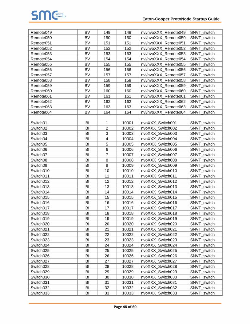
Appendix B.4. 344640003 Greengate Mappings to BACnet, Modbus and LonWorks
Point Name
BACnet
Object
Type
BACnet
Object
ID
Modbus
Register Lon Name Lon SNVT
Reset BV 1001 201 nviXXX_Reset SNVT_switch
Relay01 BV 1 1 nvi/nvoXXX_Relay001 SNVT_switch
Relay02 BV 2 2 nvi/nvoXXX_Relay002 SNVT_switch

Eaton-Cooper ProtoNode Startup Guide
Page 47 of 60
Relay03 BV 3 3 nvi/nvoXXX_Relay003 SNVT_switch
Remote01 BV 101 101 nvi/nvoXXX_Remote001 SNVT_switch
Remote02 BV 102 102 nvi/nvoXXX_Remote002 SNVT_switch
Remote03 BV 103 103 nvi/nvoXXX_Remote003 SNVT_switch
Remote04 BV 104 104 nvi/nvoXXX_Remote004 SNVT_switch
Remote05 BV 105 105 nvi/nvoXXX_Remote005 SNVT_switch
Remote06 BV 106 106 nvi/nvoXXX_Remote006 SNVT_switch
Remote07 BV 107 107 nvi/nvoXXX_Remote007 SNVT_switch
Remote08 BV 108 108 nvi/nvoXXX_Remote008 SNVT_switch
Remote09 BV 109 109 nvi/nvoXXX_Remote009 SNVT_switch
Remote010 BV 110 110 nvi/nvoXXX_Remote010 SNVT_switch
Remote011 BV 111 111 nvi/nvoXXX_Remote011 SNVT_switch
Remote012 BV 112 112 nvi/nvoXXX_Remote012 SNVT_switch
Remote013 BV 113 113 nvi/nvoXXX_Remote013 SNVT_switch
Remote014 BV 114 114 nvi/nvoXXX_Remote014 SNVT_switch
Remote015 BV 115 115 nvi/nvoXXX_Remote015 SNVT_switch
Remote016 BV 116 116 nvi/nvoXXX_Remote016 SNVT_switch
Remote017 BV 117 117 nvi/nvoXXX_Remote017 SNVT_switch
Remote018 BV 118 118 nvi/nvoXXX_Remote018 SNVT_switch
Remote019 BV 119 119 nvi/nvoXXX_Remote019 SNVT_switch
Remote020 BV 120 120 nvi/nvoXXX_Remote020 SNVT_switch
Remote021 BV 121 121 nvi/nvoXXX_Remote021 SNVT_switch
Remote022 BV 122 122 nvi/nvoXXX_Remote022 SNVT_switch
Remote023 BV 123 123 nvi/nvoXXX_Remote023 SNVT_switch
Remote024 BV 124 124 nvi/nvoXXX_Remote024 SNVT_switch
Remote025 BV 125 125 nvi/nvoXXX_Remote025 SNVT_switch
Remote026 BV 126 126 nvi/nvoXXX_Remote026 SNVT_switch
Remote027 BV 127 127 nvi/nvoXXX_Remote027 SNVT_switch
Remote028 BV 128 128 nvi/nvoXXX_Remote028 SNVT_switch
Remote029 BV 129 129 nvi/nvoXXX_Remote029 SNVT_switch
Remote030 BV 130 130 nvi/nvoXXX_Remote030 SNVT_switch
Remote031 BV 131 131 nvi/nvoXXX_Remote031 SNVT_switch
Remote032 BV 132 132 nvi/nvoXXX_Remote032 SNVT_switch
Remote033 BV 133 133 nvi/nvoXXX_Remote033 SNVT_switch
Remote034 BV 134 134 nvi/nvoXXX_Remote034 SNVT_switch
Remote035 BV 135 135 nvi/nvoXXX_Remote035 SNVT_switch
Remote036 BV 136 136 nvi/nvoXXX_Remote036 SNVT_switch
Remote037 BV 137 137 nvi/nvoXXX_Remote037 SNVT_switch
Remote038 BV 138 138 nvi/nvoXXX_Remote038 SNVT_switch
Remote039 BV 139 139 nvi/nvoXXX_Remote039 SNVT_switch
Remote040 BV 140 140 nvi/nvoXXX_Remote040 SNVT_switch
Remote041 BV 141 141 nvi/nvoXXX_Remote041 SNVT_switch
Remote042 BV 142 142 nvi/nvoXXX_Remote042 SNVT_switch
Remote043 BV 143 143 nvi/nvoXXX_Remote043 SNVT_switch
Remote044 BV 144 144 nvi/nvoXXX_Remote044 SNVT_switch
Remote045 BV 145 145 nvi/nvoXXX_Remote045 SNVT_switch
Remote046 BV 146 146 nvi/nvoXXX_Remote046 SNVT_switch
Remote047 BV 147 147 nvi/nvoXXX_Remote047 SNVT_switch
Remote048 BV 148 148 nvi/nvoXXX_Remote048 SNVT_switch
Eaton-Cooper ProtoNode Startup Guide
Page 48 of 60
Remote049 BV 149 149 nvi/nvoXXX_Remote049 SNVT_switch
Remote050 BV 150 150 nvi/nvoXXX_Remote050 SNVT_switch
Remote051 BV 151 151 nvi/nvoXXX_Remote051 SNVT_switch
Remote052 BV 152 152 nvi/nvoXXX_Remote052 SNVT_switch
Remote053 BV 153 153 nvi/nvoXXX_Remote053 SNVT_switch
Remote054 BV 154 154 nvi/nvoXXX_Remote054 SNVT_switch
Remote055 BV 155 155 nvi/nvoXXX_Remote055 SNVT_switch
Remote056 BV 156 156 nvi/nvoXXX_Remote056 SNVT_switch
Remote057 BV 157 157 nvi/nvoXXX_Remote057 SNVT_switch
Remote058 BV 158 158 nvi/nvoXXX_Remote058 SNVT_switch
Remote059 BV 159 159 nvi/nvoXXX_Remote059 SNVT_switch
Remote060 BV 160 160 nvi/nvoXXX_Remote060 SNVT_switch
Remote061 BV 161 161 nvi/nvoXXX_Remote061 SNVT_switch
Remote062 BV 162 162 nvi/nvoXXX_Remote062 SNVT_switch
Remote063 BV 163 163 nvi/nvoXXX_Remote063 SNVT_switch
Remote064 BV 164 164 nvi/nvoXXX_Remote064 SNVT_switch
Switch01 BI 1 10001 nvoXXX_Switch001 SNVT_switch
Switch02 BI 2 10002 nvoXXX_Switch002 SNVT_switch
Switch03 BI 3 10003 nvoXXX_Switch003 SNVT_switch
Switch04 BI 4 10004 nvoXXX_Switch004 SNVT_switch
Switch05 BI 5 10005 nvoXXX_Switch005 SNVT_switch
Switch06 BI 6 10006 nvoXXX_Switch006 SNVT_switch
Switch07 BI 7 10007 nvoXXX_Switch007 SNVT_switch
Switch08 BI 8 10008 nvoXXX_Switch008 SNVT_switch
Switch09 BI 9 10009 nvoXXX_Switch009 SNVT_switch
Switch010 BI 10 10010 nvoXXX_Switch010 SNVT_switch
Switch011 BI 11 10011 nvoXXX_Switch011 SNVT_switch
Switch012 BI 12 10012 nvoXXX_Switch012 SNVT_switch
Switch013 BI 13 10013 nvoXXX_Switch013 SNVT_switch
Switch014 BI 14 10014 nvoXXX_Switch014 SNVT_switch
Switch015 BI 15 10015 nvoXXX_Switch015 SNVT_switch
Switch016 BI 16 10016 nvoXXX_Switch016 SNVT_switch
Switch017 BI 17 10017 nvoXXX_Switch017 SNVT_switch
Switch018 BI 18 10018 nvoXXX_Switch018 SNVT_switch
Switch019 BI 19 10019 nvoXXX_Switch019 SNVT_switch
Switch020 BI 20 10020 nvoXXX_Switch020 SNVT_switch
Switch021 BI 21 10021 nvoXXX_Switch021 SNVT_switch
Switch022 BI 22 10022 nvoXXX_Switch022 SNVT_switch
Switch023 BI 23 10023 nvoXXX_Switch023 SNVT_switch
Switch024 BI 24 10024 nvoXXX_Switch024 SNVT_switch
Switch025 BI 25 10025 nvoXXX_Switch025 SNVT_switch
Switch026 BI 26 10026 nvoXXX_Switch026 SNVT_switch
Switch027 BI 27 10027 nvoXXX_Switch027 SNVT_switch
Switch028 BI 28 10028 nvoXXX_Switch028 SNVT_switch
Switch029 BI 29 10029 nvoXXX_Switch029 SNVT_switch
Switch030 BI 30 10030 nvoXXX_Switch030 SNVT_switch
Switch031 BI 31 10031 nvoXXX_Switch031 SNVT_switch
Switch032 BI 32 10032 nvoXXX_Switch032 SNVT_switch
Switch033 BI 33 10033 nvoXXX_Switch033 SNVT_switch
Eaton-Cooper ProtoNode Startup Guide
Page 49 of 60
Switch034 BI 34 10034 nvoXXX_Switch034 SNVT_switch
Switch035 BI 35 10035 nvoXXX_Switch035 SNVT_switch
Switch036 BI 36 10036 nvoXXX_Switch036 SNVT_switch
Switch037 BI 37 10037 nvoXXX_Switch037 SNVT_switch
Switch038 BI 38 10038 nvoXXX_Switch038 SNVT_switch
Switch039 BI 39 10039 nvoXXX_Switch039 SNVT_switch
Switch040 BI 40 10040 nvoXXX_Switch040 SNVT_switch
Switch041 BI 41 10041 nvoXXX_Switch041 SNVT_switch
Switch042 BI 42 10042 nvoXXX_Switch042 SNVT_switch
Switch043 BI 43 10043 nvoXXX_Switch043 SNVT_switch
Switch044 BI 44 10044 nvoXXX_Switch044 SNVT_switch
AI01 AI 1 30001 nvoXXX_AI01 SNVT_count_f
AI02 AI 2 30002 nvoXXX_AI02 SNVT_count_f
AI03 AI 3 30003 nvoXXX_AI03 SNVT_count_f
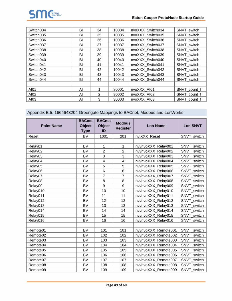
Appendix B.5. 1664643204 Greengate Mappings to BACnet, Modbus and LonWorks
Point Name
BACnet
Object
Type
BACnet
Object
ID
Modbus
Register Lon Name Lon SNVT
Reset BV 1001 201 nviXXX_Reset SNVT_switch
Relay01 BV 1 1 nvi/nvoXXX_Relay001 SNVT_switch
Relay02 BV 2 2 nvi/nvoXXX_Relay002 SNVT_switch
Relay03 BV 3 3 nvi/nvoXXX_Relay003 SNVT_switch
Relay04 BV 4 4 nvi/nvoXXX_Relay004 SNVT_switch
Relay05 BV 5 5 nvi/nvoXXX_Relay005 SNVT_switch
Relay06 BV 6 6 nvi/nvoXXX_Relay006 SNVT_switch
Relay07 BV 7 7 nvi/nvoXXX_Relay007 SNVT_switch
Relay08 BV 8 8 nvi/nvoXXX_Relay008 SNVT_switch
Relay09 BV 9 9 nvi/nvoXXX_Relay009 SNVT_switch
Relay010 BV 10 10 nvi/nvoXXX_Relay010 SNVT_switch
Relay011 BV 11 11 nvi/nvoXXX_Relay011 SNVT_switch
Relay012 BV 12 12 nvi/nvoXXX_Relay012 SNVT_switch
Relay013 BV 13 13 nvi/nvoXXX_Relay013 SNVT_switch
Relay014 BV 14 14 nvi/nvoXXX_Relay014 SNVT_switch
Relay015 BV 15 15 nvi/nvoXXX_Relay015 SNVT_switch
Relay016 BV 16 16 nvi/nvoXXX_Relay016 SNVT_switch
Remote01 BV 101 101 nvi/nvoXXX_Remote001 SNVT_switch
Remote02 BV 102 102 nvi/nvoXXX_Remote002 SNVT_switch
Remote03 BV 103 103 nvi/nvoXXX_Remote003 SNVT_switch
Remote04 BV 104 104 nvi/nvoXXX_Remote004 SNVT_switch
Remote05 BV 105 105 nvi/nvoXXX_Remote005 SNVT_switch
Remote06 BV 106 106 nvi/nvoXXX_Remote006 SNVT_switch
Remote07 BV 107 107 nvi/nvoXXX_Remote007 SNVT_switch
Remote08 BV 108 108 nvi/nvoXXX_Remote008 SNVT_switch
Remote09 BV 109 109 nvi/nvoXXX_Remote009 SNVT_switch

Eaton-Cooper ProtoNode Startup Guide
Page 50 of 60
Remote010 BV 110 110 nvi/nvoXXX_Remote010 SNVT_switch
Remote011 BV 111 111 nvi/nvoXXX_Remote011 SNVT_switch
Remote012 BV 112 112 nvi/nvoXXX_Remote012 SNVT_switch
Remote013 BV 113 113 nvi/nvoXXX_Remote013 SNVT_switch
Remote014 BV 114 114 nvi/nvoXXX_Remote014 SNVT_switch
Remote015 BV 115 115 nvi/nvoXXX_Remote015 SNVT_switch
Remote016 BV 116 116 nvi/nvoXXX_Remote016 SNVT_switch
Remote017 BV 117 117 nvi/nvoXXX_Remote017 SNVT_switch
Remote018 BV 118 118 nvi/nvoXXX_Remote018 SNVT_switch
Remote019 BV 119 119 nvi/nvoXXX_Remote019 SNVT_switch
Remote020 BV 120 120 nvi/nvoXXX_Remote020 SNVT_switch
Remote021 BV 121 121 nvi/nvoXXX_Remote021 SNVT_switch
Remote022 BV 122 122 nvi/nvoXXX_Remote022 SNVT_switch
Remote023 BV 123 123 nvi/nvoXXX_Remote023 SNVT_switch
Remote024 BV 124 124 nvi/nvoXXX_Remote024 SNVT_switch
Remote025 BV 125 125 nvi/nvoXXX_Remote025 SNVT_switch
Remote026 BV 126 126 nvi/nvoXXX_Remote026 SNVT_switch
Remote027 BV 127 127 nvi/nvoXXX_Remote027 SNVT_switch
Remote028 BV 128 128 nvi/nvoXXX_Remote028 SNVT_switch
Remote029 BV 129 129 nvi/nvoXXX_Remote029 SNVT_switch
Remote030 BV 130 130 nvi/nvoXXX_Remote030 SNVT_switch
Remote031 BV 131 131 nvi/nvoXXX_Remote031 SNVT_switch
Remote032 BV 132 132 nvi/nvoXXX_Remote032 SNVT_switch
Remote033 BV 133 133 nvi/nvoXXX_Remote033 SNVT_switch
Remote034 BV 134 134 nvi/nvoXXX_Remote034 SNVT_switch
Remote035 BV 135 135 nvi/nvoXXX_Remote035 SNVT_switch
Remote036 BV 136 136 nvi/nvoXXX_Remote036 SNVT_switch
Remote037 BV 137 137 nvi/nvoXXX_Remote037 SNVT_switch
Remote038 BV 138 138 nvi/nvoXXX_Remote038 SNVT_switch
Remote039 BV 139 139 nvi/nvoXXX_Remote039 SNVT_switch
Remote040 BV 140 140 nvi/nvoXXX_Remote040 SNVT_switch
Remote041 BV 141 141 nvi/nvoXXX_Remote041 SNVT_switch
Remote042 BV 142 142 nvi/nvoXXX_Remote042 SNVT_switch
Remote043 BV 143 143 nvi/nvoXXX_Remote043 SNVT_switch
Remote044 BV 144 144 nvi/nvoXXX_Remote044 SNVT_switch
Remote045 BV 145 145 nvi/nvoXXX_Remote045 SNVT_switch
Remote046 BV 146 146 nvi/nvoXXX_Remote046 SNVT_switch
Remote047 BV 147 147 nvi/nvoXXX_Remote047 SNVT_switch
Remote048 BV 148 148 nvi/nvoXXX_Remote048 SNVT_switch
Remote049 BV 149 149 nvi/nvoXXX_Remote049 SNVT_switch
Remote050 BV 150 150 nvi/nvoXXX_Remote050 SNVT_switch
Remote051 BV 151 151 nvi/nvoXXX_Remote051 SNVT_switch
Remote052 BV 152 152 nvi/nvoXXX_Remote052 SNVT_switch
Remote053 BV 153 153 nvi/nvoXXX_Remote053 SNVT_switch
Remote054 BV 154 154 nvi/nvoXXX_Remote054 SNVT_switch
Remote055 BV 155 155 nvi/nvoXXX_Remote055 SNVT_switch
Remote056 BV 156 156 nvi/nvoXXX_Remote056 SNVT_switch
Remote057 BV 157 157 nvi/nvoXXX_Remote057 SNVT_switch
Remote058 BV 158 158 nvi/nvoXXX_Remote058 SNVT_switch
Remote059 BV 159 159 nvi/nvoXXX_Remote059 SNVT_switch

Eaton-Cooper ProtoNode Startup Guide
Page 51 of 60
Remote060 BV 160 160 nvi/nvoXXX_Remote060 SNVT_switch
Remote061 BV 161 161 nvi/nvoXXX_Remote061 SNVT_switch
Remote062 BV 162 162 nvi/nvoXXX_Remote062 SNVT_switch
Remote063 BV 163 163 nvi/nvoXXX_Remote063 SNVT_switch
Remote064 BV 164 164 nvi/nvoXXX_Remote064 SNVT_switch
Switch01 BI 1 10001 nvoXXX_Switch001 SNVT_switch
Switch02 BI 2 10002 nvoXXX_Switch002 SNVT_switch
Switch03 BI 3 10003 nvoXXX_Switch003 SNVT_switch
Switch04 BI 4 10004 nvoXXX_Switch004 SNVT_switch
Switch05 BI 5 10005 nvoXXX_Switch005 SNVT_switch
Switch06 BI 6 10006 nvoXXX_Switch006 SNVT_switch
Switch07 BI 7 10007 nvoXXX_Switch007 SNVT_switch
Switch08 BI 8 10008 nvoXXX_Switch008 SNVT_switch
Switch09 BI 9 10009 nvoXXX_Switch009 SNVT_switch
Switch010 BI 10 10010 nvoXXX_Switch010 SNVT_switch
Switch011 BI 11 10011 nvoXXX_Switch011 SNVT_switch
Switch012 BI 12 10012 nvoXXX_Switch012 SNVT_switch
Switch013 BI 13 10013 nvoXXX_Switch013 SNVT_switch
Switch014 BI 14 10014 nvoXXX_Switch014 SNVT_switch
Switch015 BI 15 10015 nvoXXX_Switch015 SNVT_switch
Switch016 BI 16 10016 nvoXXX_Switch016 SNVT_switch
Switch017 BI 17 10017 nvoXXX_Switch017 SNVT_switch
Switch018 BI 18 10018 nvoXXX_Switch018 SNVT_switch
Switch019 BI 19 10019 nvoXXX_Switch019 SNVT_switch
Switch020 BI 20 10020 nvoXXX_Switch020 SNVT_switch
Switch021 BI 21 10021 nvoXXX_Switch021 SNVT_switch
Switch022 BI 22 10022 nvoXXX_Switch022 SNVT_switch
Switch023 BI 23 10023 nvoXXX_Switch023 SNVT_switch
Switch024 BI 24 10024 nvoXXX_Switch024 SNVT_switch
Switch025 BI 25 10025 nvoXXX_Switch025 SNVT_switch
Switch026 BI 26 10026 nvoXXX_Switch026 SNVT_switch
Switch027 BI 27 10027 nvoXXX_Switch027 SNVT_switch
Switch028 BI 28 10028 nvoXXX_Switch028 SNVT_switch
Switch029 BI 29 10029 nvoXXX_Switch029 SNVT_switch
Switch030 BI 30 10030 nvoXXX_Switch030 SNVT_switch
Switch031 BI 31 10031 nvoXXX_Switch031 SNVT_switch
Switch032 BI 32 10032 nvoXXX_Switch032 SNVT_switch
Switch033 BI 33 10033 nvoXXX_Switch033 SNVT_switch
Switch034 BI 34 10034 nvoXXX_Switch034 SNVT_switch
Switch035 BI 35 10035 nvoXXX_Switch035 SNVT_switch
Switch036 BI 36 10036 nvoXXX_Switch036 SNVT_switch
Switch037 BI 37 10037 nvoXXX_Switch037 SNVT_switch
Switch038 BI 38 10038 nvoXXX_Switch038 SNVT_switch
Switch039 BI 39 10039 nvoXXX_Switch039 SNVT_switch
Switch040 BI 40 10040 nvoXXX_Switch040 SNVT_switch
Switch041 BI 41 10041 nvoXXX_Switch041 SNVT_switch
Switch042 BI 42 10042 nvoXXX_Switch042 SNVT_switch
Switch043 BI 43 10043 nvoXXX_Switch043 SNVT_switch
Switch044 BI 44 10044 nvoXXX_Switch044 SNVT_switch

Eaton-Cooper ProtoNode Startup Guide
Page 52 of 60
Switch045 BI 45 10045 nvoXXX_Switch045 SNVT_switch
Switch046 BI 46 10046 nvoXXX_Switch046 SNVT_switch
Switch047 BI 47 10047 nvoXXX_Switch047 SNVT_switch
Switch048 BI 48 10048 nvoXXX_Switch048 SNVT_switch
Switch049 BI 49 10049 nvoXXX_Switch049 SNVT_switch
Switch050 BI 50 10050 nvoXXX_Switch050 SNVT_switch
Switch051 BI 51 10051 nvoXXX_Switch051 SNVT_switch
Switch052 BI 52 10052 nvoXXX_Switch052 SNVT_switch
Switch053 BI 53 10053 nvoXXX_Switch053 SNVT_switch
Switch054 BI 54 10054 nvoXXX_Switch054 SNVT_switch
Switch055 BI 55 10055 nvoXXX_Switch055 SNVT_switch
Switch056 BI 56 10056 nvoXXX_Switch056 SNVT_switch
Switch057 BI 57 10057 nvoXXX_Switch057 SNVT_switch
Switch058 BI 58 10058 nvoXXX_Switch058 SNVT_switch
Switch059 BI 59 10059 nvoXXX_Switch059 SNVT_switch
Switch060 BI 60 10060 nvoXXX_Switch060 SNVT_switch
Switch061 BI 61 10061 nvoXXX_Switch061 SNVT_switch
Switch062 BI 62 10062 nvoXXX_Switch062 SNVT_switch
Switch063 BI 63 10063 nvoXXX_Switch063 SNVT_switch
Switch064 BI 64 10064 nvoXXX_Switch064 SNVT_switch
AI_State01 BI 101 10101 nvoXXX_State01 SNVT_switch
AI_State02 BI 102 10102 nvoXXX_State02 SNVT_switch
AI_State03 BI 103 10103 nvoXXX_State03 SNVT_switch
AI_State04 BI 104 10104 nvoXXX_State04 SNVT_switch
AI_State05 BI 105 10105 nvoXXX_State05 SNVT_switch
AI_State06 BI 106 10106 nvoXXX_State06 SNVT_switch
AI_State07 BI 107 10107 nvoXXX_State07 SNVT_switch
AI_State08 BI 108 10108 nvoXXX_State08 SNVT_switch
AI_State09 BI 109 10109 nvoXXX_State09 SNVT_switch
AI_State010 BI 110 10110 nvoXXX_State10 SNVT_switch
AI_State011 BI 111 10111 nvoXXX_State11 SNVT_switch
AI_State012 BI 112 10112 nvoXXX_State12 SNVT_switch
AI_State013 BI 113 10113 nvoXXX_State13 SNVT_switch
AI_State014 BI 114 10114 nvoXXX_State14 SNVT_switch
AI_State015 BI 115 10115 nvoXXX_State15 SNVT_switch
AI_State016 BI 116 10116 nvoXXX_State16 SNVT_switch
AI_State017 BI 117 10117 nvoXXX_State17 SNVT_switch
AI_State018 BI 118 10118 nvoXXX_State18 SNVT_switch
AI_State019 BI 119 10119 nvoXXX_State19 SNVT_switch
AI_State020 BI 120 10120 nvoXXX_State20 SNVT_switch
AI_State021 BI 121 10121 nvoXXX_State21 SNVT_switch
AI_State022 BI 122 10122 nvoXXX_State22 SNVT_switch
AI_State023 BI 123 10123 nvoXXX_State23 SNVT_switch
AI_State024 BI 124 10124 nvoXXX_State24 SNVT_switch
AI_State025 BI 125 10125 nvoXXX_State25 SNVT_switch
AI_State026 BI 126 10126 nvoXXX_State26 SNVT_switch
AI_State027 BI 127 10127 nvoXXX_State27 SNVT_switch
AI_State028 BI 128 10128 nvoXXX_State28 SNVT_switch
AI_State029 BI 129 10129 nvoXXX_State29 SNVT_switch

Eaton-Cooper ProtoNode Startup Guide
Page 53 of 60
AI_State030 BI 130 10130 nvoXXX_State30 SNVT_switch
AI_State031 BI 131 10131 nvoXXX_State31 SNVT_switch
AI_State032 BI 132 10132 nvoXXX_State32 SNVT_switch
AI01 AI 1 30001 nvoXXX_AI01 SNVT_switch
AI02 AI 2 30002 nvoXXX_AI02 SNVT_switch
AI03 AI 3 30003 nvoXXX_AI03 SNVT_switch
AI04 AI 4 30004 nvoXXX_AI04 SNVT_switch
Appendix B.6. 6464643200 Greengate Mappings to BACnet, Modbus and LonWorks
Point Name
BACnet
Object
Type
BACnet
Object
ID
Modbus
Register Lon Name Lon SNVT
Reset BV 1001 201 nviXXX_Reset SNVT_switch
Relay01 BV 1 1 nvi/nvoXXX_Relay001 SNVT_switch
Relay02 BV 2 2 nvi/nvoXXX_Relay002 SNVT_switch
Relay03 BV 3 3 nvi/nvoXXX_Relay003 SNVT_switch
Relay04 BV 4 4 nvi/nvoXXX_Relay004 SNVT_switch
Relay05 BV 5 5 nvi/nvoXXX_Relay005 SNVT_switch
Relay06 BV 6 6 nvi/nvoXXX_Relay006 SNVT_switch
Relay07 BV 7 7 nvi/nvoXXX_Relay007 SNVT_switch
Relay08 BV 8 8 nvi/nvoXXX_Relay008 SNVT_switch
Relay09 BV 9 9 nvi/nvoXXX_Relay009 SNVT_switch
Relay010 BV 10 10 nvi/nvoXXX_Relay010 SNVT_switch
Relay011 BV 11 11 nvi/nvoXXX_Relay011 SNVT_switch
Relay012 BV 12 12 nvi/nvoXXX_Relay012 SNVT_switch
Relay013 BV 13 13 nvi/nvoXXX_Relay013 SNVT_switch
Relay014 BV 14 14 nvi/nvoXXX_Relay014 SNVT_switch
Relay015 BV 15 15 nvi/nvoXXX_Relay015 SNVT_switch
Relay016 BV 16 16 nvi/nvoXXX_Relay016 SNVT_switch
Relay017 BV 17 17 nvi/nvoXXX_Relay017 SNVT_switch
Relay018 BV 18 18 nvi/nvoXXX_Relay018 SNVT_switch
Relay019 BV 19 19 nvi/nvoXXX_Relay019 SNVT_switch
Relay020 BV 20 20 nvi/nvoXXX_Relay020 SNVT_switch
Relay021 BV 21 21 nvi/nvoXXX_Relay021 SNVT_switch
Relay022 BV 22 22 nvi/nvoXXX_Relay022 SNVT_switch
Relay023 BV 23 23 nvi/nvoXXX_Relay023 SNVT_switch
Relay024 BV 24 24 nvi/nvoXXX_Relay024 SNVT_switch
Relay025 BV 25 25 nvi/nvoXXX_Relay025 SNVT_switch
Relay026 BV 26 26 nvi/nvoXXX_Relay026 SNVT_switch
Relay027 BV 27 27 nvi/nvoXXX_Relay027 SNVT_switch
Relay028 BV 28 28 nvi/nvoXXX_Relay028 SNVT_switch
Relay029 BV 29 29 nvi/nvoXXX_Relay029 SNVT_switch
Relay030 BV 30 30 nvi/nvoXXX_Relay030 SNVT_switch
Relay031 BV 31 31 nvi/nvoXXX_Relay031 SNVT_switch
Relay032 BV 32 32 nvi/nvoXXX_Relay032 SNVT_switch
Relay033 BV 33 33 nvi/nvoXXX_Relay033 SNVT_switch

Eaton-Cooper ProtoNode Startup Guide
Page 54 of 60
Relay034 BV 34 34 nvi/nvoXXX_Relay034 SNVT_switch
Relay035 BV 35 35 nvi/nvoXXX_Relay035 SNVT_switch
Relay036 BV 36 36 nvi/nvoXXX_Relay036 SNVT_switch
Relay037 BV 37 37 nvi/nvoXXX_Relay037 SNVT_switch
Relay038 BV 38 38 nvi/nvoXXX_Relay038 SNVT_switch
Relay039 BV 39 39 nvi/nvoXXX_Relay039 SNVT_switch
Relay040 BV 40 40 nvi/nvoXXX_Relay040 SNVT_switch
Relay041 BV 41 41 nvi/nvoXXX_Relay041 SNVT_switch
Relay042 BV 42 42 nvi/nvoXXX_Relay042 SNVT_switch
Relay043 BV 43 43 nvi/nvoXXX_Relay043 SNVT_switch
Relay044 BV 44 44 nvi/nvoXXX_Relay044 SNVT_switch
Relay045 BV 45 45 nvi/nvoXXX_Relay045 SNVT_switch
Relay046 BV 46 46 nvi/nvoXXX_Relay046 SNVT_switch
Relay047 BV 47 47 nvi/nvoXXX_Relay047 SNVT_switch
Relay048 BV 48 48 nvi/nvoXXX_Relay048 SNVT_switch
Relay049 BV 49 49 nvi/nvoXXX_Relay049 SNVT_switch
Relay050 BV 50 50 nvi/nvoXXX_Relay050 SNVT_switch
Relay051 BV 51 51 nvi/nvoXXX_Relay051 SNVT_switch
Relay052 BV 52 52 nvi/nvoXXX_Relay052 SNVT_switch
Relay053 BV 53 53 nvi/nvoXXX_Relay053 SNVT_switch
Relay054 BV 54 54 nvi/nvoXXX_Relay054 SNVT_switch
Relay055 BV 55 55 nvi/nvoXXX_Relay055 SNVT_switch
Relay056 BV 56 56 nvi/nvoXXX_Relay056 SNVT_switch
Relay057 BV 57 57 nvi/nvoXXX_Relay057 SNVT_switch
Relay058 BV 58 58 nvi/nvoXXX_Relay058 SNVT_switch
Relay059 BV 59 59 nvi/nvoXXX_Relay059 SNVT_switch
Relay060 BV 60 60 nvi/nvoXXX_Relay060 SNVT_switch
Relay061 BV 61 61 nvi/nvoXXX_Relay061 SNVT_switch
Relay062 BV 62 62 nvi/nvoXXX_Relay062 SNVT_switch
Relay063 BV 63 63 nvi/nvoXXX_Relay063 SNVT_switch
Relay064 BV 64 64 nvi/nvoXXX_Relay064 SNVT_switch
Remote01 BV 101 101 nvi/nvoXXX_Remote001 SNVT_switch
Remote02 BV 102 102 nvi/nvoXXX_Remote002 SNVT_switch
Remote03 BV 103 103 nvi/nvoXXX_Remote003 SNVT_switch
Remote04 BV 104 104 nvi/nvoXXX_Remote004 SNVT_switch
Remote05 BV 105 105 nvi/nvoXXX_Remote005 SNVT_switch
Remote06 BV 106 106 nvi/nvoXXX_Remote006 SNVT_switch
Remote07 BV 107 107 nvi/nvoXXX_Remote007 SNVT_switch
Remote08 BV 108 108 nvi/nvoXXX_Remote008 SNVT_switch
Remote09 BV 109 109 nvi/nvoXXX_Remote009 SNVT_switch
Remote010 BV 110 110 nvi/nvoXXX_Remote010 SNVT_switch
Remote011 BV 111 111 nvi/nvoXXX_Remote011 SNVT_switch
Remote012 BV 112 112 nvi/nvoXXX_Remote012 SNVT_switch
Remote013 BV 113 113 nvi/nvoXXX_Remote013 SNVT_switch
Remote014 BV 114 114 nvi/nvoXXX_Remote014 SNVT_switch
Remote015 BV 115 115 nvi/nvoXXX_Remote015 SNVT_switch
Remote016 BV 116 116 nvi/nvoXXX_Remote016 SNVT_switch
Remote017 BV 117 117 nvi/nvoXXX_Remote017 SNVT_switch
Remote018 BV 118 118 nvi/nvoXXX_Remote018 SNVT_switch

Eaton-Cooper ProtoNode Startup Guide
Page 55 of 60
Remote019 BV 119 119 nvi/nvoXXX_Remote019 SNVT_switch
Remote020 BV 120 120 nvi/nvoXXX_Remote020 SNVT_switch
Remote021 BV 121 121 nvi/nvoXXX_Remote021 SNVT_switch
Remote022 BV 122 122 nvi/nvoXXX_Remote022 SNVT_switch
Remote023 BV 123 123 nvi/nvoXXX_Remote023 SNVT_switch
Remote024 BV 124 124 nvi/nvoXXX_Remote024 SNVT_switch
Remote025 BV 125 125 nvi/nvoXXX_Remote025 SNVT_switch
Remote026 BV 126 126 nvi/nvoXXX_Remote026 SNVT_switch
Remote027 BV 127 127 nvi/nvoXXX_Remote027 SNVT_switch
Remote028 BV 128 128 nvi/nvoXXX_Remote028 SNVT_switch
Remote029 BV 129 129 nvi/nvoXXX_Remote029 SNVT_switch
Remote030 BV 130 130 nvi/nvoXXX_Remote030 SNVT_switch
Remote031 BV 131 131 nvi/nvoXXX_Remote031 SNVT_switch
Remote032 BV 132 132 nvi/nvoXXX_Remote032 SNVT_switch
Remote033 BV 133 133 nvi/nvoXXX_Remote033 SNVT_switch
Remote034 BV 134 134 nvi/nvoXXX_Remote034 SNVT_switch
Remote035 BV 135 135 nvi/nvoXXX_Remote035 SNVT_switch
Remote036 BV 136 136 nvi/nvoXXX_Remote036 SNVT_switch
Remote037 BV 137 137 nvi/nvoXXX_Remote037 SNVT_switch
Remote038 BV 138 138 nvi/nvoXXX_Remote038 SNVT_switch
Remote039 BV 139 139 nvi/nvoXXX_Remote039 SNVT_switch
Remote040 BV 140 140 nvi/nvoXXX_Remote040 SNVT_switch
Remote041 BV 141 141 nvi/nvoXXX_Remote041 SNVT_switch
Remote042 BV 142 142 nvi/nvoXXX_Remote042 SNVT_switch
Remote043 BV 143 143 nvi/nvoXXX_Remote043 SNVT_switch
Remote044 BV 144 144 nvi/nvoXXX_Remote044 SNVT_switch
Remote045 BV 145 145 nvi/nvoXXX_Remote045 SNVT_switch
Remote046 BV 146 146 nvi/nvoXXX_Remote046 SNVT_switch
Remote047 BV 147 147 nvi/nvoXXX_Remote047 SNVT_switch
Remote048 BV 148 148 nvi/nvoXXX_Remote048 SNVT_switch
Remote049 BV 149 149 nvi/nvoXXX_Remote049 SNVT_switch
Remote050 BV 150 150 nvi/nvoXXX_Remote050 SNVT_switch
Remote051 BV 151 151 nvi/nvoXXX_Remote051 SNVT_switch
Remote052 BV 152 152 nvi/nvoXXX_Remote052 SNVT_switch
Remote053 BV 153 153 nvi/nvoXXX_Remote053 SNVT_switch
Remote054 BV 154 154 nvi/nvoXXX_Remote054 SNVT_switch
Remote055 BV 155 155 nvi/nvoXXX_Remote055 SNVT_switch
Remote056 BV 156 156 nvi/nvoXXX_Remote056 SNVT_switch
Remote057 BV 157 157 nvi/nvoXXX_Remote057 SNVT_switch
Remote058 BV 158 158 nvi/nvoXXX_Remote058 SNVT_switch
Remote059 BV 159 159 nvi/nvoXXX_Remote059 SNVT_switch
Remote060 BV 160 160 nvi/nvoXXX_Remote060 SNVT_switch
Remote061 BV 161 161 nvi/nvoXXX_Remote061 SNVT_switch
Remote062 BV 162 162 nvi/nvoXXX_Remote062 SNVT_switch
Remote063 BV 163 163 nvi/nvoXXX_Remote063 SNVT_switch
Remote064 BV 164 164 nvi/nvoXXX_Remote064 SNVT_switch
Switch01 BI 1 10001 nvoXXX_Switch001 SNVT_switch
Switch02 BI 2 10002 nvoXXX_Switch002 SNVT_switch
Switch03 BI 3 10003 nvoXXX_Switch003 SNVT_switch

Eaton-Cooper ProtoNode Startup Guide
Page 56 of 60
Switch04 BI 4 10004 nvoXXX_Switch004 SNVT_switch
Switch05 BI 5 10005 nvoXXX_Switch005 SNVT_switch
Switch06 BI 6 10006 nvoXXX_Switch006 SNVT_switch
Switch07 BI 7 10007 nvoXXX_Switch007 SNVT_switch
Switch08 BI 8 10008 nvoXXX_Switch008 SNVT_switch
Switch09 BI 9 10009 nvoXXX_Switch009 SNVT_switch
Switch010 BI 10 10010 nvoXXX_Switch010 SNVT_switch
Switch011 BI 11 10011 nvoXXX_Switch011 SNVT_switch
Switch012 BI 12 10012 nvoXXX_Switch012 SNVT_switch
Switch013 BI 13 10013 nvoXXX_Switch013 SNVT_switch
Switch014 BI 14 10014 nvoXXX_Switch014 SNVT_switch
Switch015 BI 15 10015 nvoXXX_Switch015 SNVT_switch
Switch016 BI 16 10016 nvoXXX_Switch016 SNVT_switch
Switch017 BI 17 10017 nvoXXX_Switch017 SNVT_switch
Switch018 BI 18 10018 nvoXXX_Switch018 SNVT_switch
Switch019 BI 19 10019 nvoXXX_Switch019 SNVT_switch
Switch020 BI 20 10020 nvoXXX_Switch020 SNVT_switch
Switch021 BI 21 10021 nvoXXX_Switch021 SNVT_switch
Switch022 BI 22 10022 nvoXXX_Switch022 SNVT_switch
Switch023 BI 23 10023 nvoXXX_Switch023 SNVT_switch
Switch024 BI 24 10024 nvoXXX_Switch024 SNVT_switch
Switch025 BI 25 10025 nvoXXX_Switch025 SNVT_switch
Switch026 BI 26 10026 nvoXXX_Switch026 SNVT_switch
Switch027 BI 27 10027 nvoXXX_Switch027 SNVT_switch
Switch028 BI 28 10028 nvoXXX_Switch028 SNVT_switch
Switch029 BI 29 10029 nvoXXX_Switch029 SNVT_switch
Switch030 BI 30 10030 nvoXXX_Switch030 SNVT_switch
Switch031 BI 31 10031 nvoXXX_Switch031 SNVT_switch
Switch032 BI 32 10032 nvoXXX_Switch032 SNVT_switch
Switch033 BI 33 10033 nvoXXX_Switch033 SNVT_switch
Switch034 BI 34 10034 nvoXXX_Switch034 SNVT_switch
Switch035 BI 35 10035 nvoXXX_Switch035 SNVT_switch
Switch036 BI 36 10036 nvoXXX_Switch036 SNVT_switch
Switch037 BI 37 10037 nvoXXX_Switch037 SNVT_switch
Switch038 BI 38 10038 nvoXXX_Switch038 SNVT_switch
Switch039 BI 39 10039 nvoXXX_Switch039 SNVT_switch
Switch040 BI 40 10040 nvoXXX_Switch040 SNVT_switch
Switch041 BI 41 10041 nvoXXX_Switch041 SNVT_switch
Switch042 BI 42 10042 nvoXXX_Switch042 SNVT_switch
Switch043 BI 43 10043 nvoXXX_Switch043 SNVT_switch
Switch044 BI 44 10044 nvoXXX_Switch044 SNVT_switch
Switch045 BI 45 10045 nvoXXX_Switch045 SNVT_switch
Switch046 BI 46 10046 nvoXXX_Switch046 SNVT_switch
Switch047 BI 47 10047 nvoXXX_Switch047 SNVT_switch
Switch048 BI 48 10048 nvoXXX_Switch048 SNVT_switch
Switch049 BI 49 10049 nvoXXX_Switch049 SNVT_switch
Switch050 BI 50 10050 nvoXXX_Switch050 SNVT_switch
Switch051 BI 51 10051 nvoXXX_Switch051 SNVT_switch
Switch052 BI 52 10052 nvoXXX_Switch052 SNVT_switch
Switch053 BI 53 10053 nvoXXX_Switch053 SNVT_switch

Eaton-Cooper ProtoNode Startup Guide
Page 57 of 60
Switch054 BI 54 10054 nvoXXX_Switch054 SNVT_switch
Switch055 BI 55 10055 nvoXXX_Switch055 SNVT_switch
Switch056 BI 56 10056 nvoXXX_Switch056 SNVT_switch
Switch057 BI 57 10057 nvoXXX_Switch057 SNVT_switch
Switch058 BI 58 10058 nvoXXX_Switch058 SNVT_switch
Switch059 BI 59 10059 nvoXXX_Switch059 SNVT_switch
Switch060 BI 60 10060 nvoXXX_Switch060 SNVT_switch
Switch061 BI 61 10061 nvoXXX_Switch061 SNVT_switch
Switch062 BI 62 10062 nvoXXX_Switch062 SNVT_switch
Switch063 BI 63 10063 nvoXXX_Switch063 SNVT_switch
Switch064 BI 64 10064 nvoXXX_Switch064 SNVT_switch
AI_State01 BI 101 10101 nvoXXX_State01 SNVT_switch
AI_State02 BI 102 10102 nvoXXX_State02 SNVT_switch
AI_State03 BI 103 10103 nvoXXX_State03 SNVT_switch
AI_State04 BI 104 10104 nvoXXX_State04 SNVT_switch
AI_State05 BI 105 10105 nvoXXX_State05 SNVT_switch
AI_State06 BI 106 10106 nvoXXX_State06 SNVT_switch
AI_State07 BI 107 10107 nvoXXX_State07 SNVT_switch
AI_State08 BI 108 10108 nvoXXX_State08 SNVT_switch
AI_State09 BI 109 10109 nvoXXX_State09 SNVT_switch
AI_State010 BI 110 10110 nvoXXX_State10 SNVT_switch
AI_State011 BI 111 10111 nvoXXX_State11 SNVT_switch
AI_State012 BI 112 10112 nvoXXX_State12 SNVT_switch
AI_State013 BI 113 10113 nvoXXX_State13 SNVT_switch
AI_State014 BI 114 10114 nvoXXX_State14 SNVT_switch
AI_State015 BI 115 10115 nvoXXX_State15 SNVT_switch
AI_State016 BI 116 10116 nvoXXX_State16 SNVT_switch
AI_State017 BI 117 10117 nvoXXX_State17 SNVT_switch
AI_State018 BI 118 10118 nvoXXX_State18 SNVT_switch
AI_State019 BI 119 10119 nvoXXX_State19 SNVT_switch
AI_State020 BI 120 10120 nvoXXX_State20 SNVT_switch
AI_State021 BI 121 10121 nvoXXX_State21 SNVT_switch
AI_State022 BI 122 10122 nvoXXX_State22 SNVT_switch
AI_State023 BI 123 10123 nvoXXX_State23 SNVT_switch
AI_State024 BI 124 10124 nvoXXX_State24 SNVT_switch
AI_State025 BI 125 10125 nvoXXX_State25 SNVT_switch
AI_State026 BI 126 10126 nvoXXX_State26 SNVT_switch
AI_State027 BI 127 10127 nvoXXX_State27 SNVT_switch
AI_State028 BI 128 10128 nvoXXX_State28 SNVT_switch
AI_State029 BI 129 10129 nvoXXX_State29 SNVT_switch
AI_State030 BI 130 10130 nvoXXX_State30 SNVT_switch
AI_State031 BI 131 10131 nvoXXX_State31 SNVT_switch
AI_State032 BI 132 10132 nvoXXX_State32 SNVT_switch

Eaton-Cooper ProtoNode Startup Guide
Page 58 of 60
Appendix B.7. Scene iLUMIN Mappings to BACnet, Modbus and LonWorks
Point Name
BACnet
Object
Type
BACnet
Object
ID
Modbus
Register Lon Name Lon SNVT
scene AO 1 40001 nvi/nvoXXXscene SNVT_count_f
sceneFT AO 2 40002 nvi/nvoXXXsceneFT SNVT_count_f
Appendix B.8. Channel iLUMIN Mappings to BACnet, Modbus and LonWorks
Point Name
BACnet
Object
Type
BACnet
Object
ID
Modbus
Register Lon Name Lon SNVT
channel AO 1 40001 nvi/nvoXXXchannel SNVT_count_f
channelFT AO 2 40002 nvi/nvoXXXchannelFT SNVT_count_f

Eaton-Cooper ProtoNode Startup Guide
Page 59 of 60
Appendix C. Reference
Appendix C.1. Specifications
ProtoNode FPC-N34 ProtoNode FPC-N35
Electrical Connections
One 6-pin Phoenix connector with: RS-485 port (+ / - / gnd) Power port (+ / - / Frame-gnd) One 3-pin Phoenix connector with: RS-485 port (+ / - / gnd) One Ethernet 10/100 BaseT port
One 6-pin Phoenix connector with: RS-485 port (+ / - / gnd) Power port (+ / - / Frame-gnd) One Ethernet 10/100 BaseT port One FTT-10 LonWorks port
Approvals:
CE Certified; TUV approved to UL 916, EN 60950-1, EN 50491-3 and CSA C22-2 standards; FCC Class A Part 15; DNP3 Conformance Tested; RoHS Compliant; CSA 205 Approved
BTL Marked LonMark Certified
Power Requirements
Multi-mode power adapter: 9-30VDC or 12 - 24VAC
Physical Dimensions
11.5 cm L x 8.3 cm W x 4.1 cm H (4.5 x 3.2 x 1.6 in.)
Weight: 0.2 kg (0.4 lbs)
Operating Temperature:
-40°C to 75°C (-40°F to167°F)
Surge Suppression EN61000-4-2 ESD EN61000-4-3 EMC EN61000-4-4 EFT
Humidity: 5 - 90% RH (non-condensing)
(Specifications subject to change without notice)
Figure 39: Specifications
Appendix C.1.1. Compliance with UL Regulations
For UL compliance, the following instructions must be met when operating ProtoNode.
The units shall be powered by listed LPS or Class 2 power supply suited to the expected operating temperature range.
The interconnecting power connector and power cable shall: o Comply with local electrical code
o Be suited to the expected operating temperature range
o Meet the current and voltage rating for ProtoNode/Net
Furthermore, the interconnecting power cable shall: o Be of length not exceeding 3.05m (118.3”)
o Be constructed of materials rated VW-1, FT-1 or better
If the unit is to be installed in an operating environment with a temperature above 65 °C, it should be installed in a Restricted Access Area requiring a key or a special tool to gain access
This device must not be connected to a LAN segment with outdoor wiring.

Eaton-Cooper ProtoNode Startup Guide
Page 60 of 60
Appendix D. Limited 2 Year Warranty
Sierra Monitor Corporation warrants its products to be free from defects in workmanship or
material under normal use and service for two years after date of shipment. Sierra Monitor
Corporation will repair or replace any equipment found to be defective during the warranty
period. Final determination of the nature and responsibility for defective or damaged equipment
will be made by Sierra Monitor Corporation personnel.
All warranties hereunder are contingent upon proper use in the application for which the product
was intended and do not cover products which have been modified or repaired without Sierra
Monitor Corporation’s approval or which have been subjected to accident, improper
maintenance, installation or application, or on which original identification marks have been
removed or altered. This Limited Warranty also will not apply to interconnecting cables or wires,
consumables or to any damage resulting from battery leakage.
In all cases Sierra Monitor Corporation’s responsibility and liability under this warranty shall be
limited to the cost of the equipment. The purchaser must obtain shipping instructions for the
prepaid return of any item under this warranty provision and compliance with such instruction
shall be a condition of this warranty.
Except for the express warranty stated above, Sierra Monitor Corporation disclaims all
warranties with regard to the products sold hereunder including all implied warranties of
merchantability and fitness and the express warranties stated herein are in lieu of all obligations
or liabilities on the part of Sierra Monitor Corporation for damages including, but not limited to,
consequential damages arising out of/or in connection with the use or performance of the
product.