project report latest
TRANSCRIPT

1.0 INTRODUCTION
An electric power system is a network of electrical components that generate
electrical power from any source of power (such as coal, water, gas, wind, nuclear energy and
oil) which then transmitted and distribute the power to nearby homes and industries. There
are three main parts in electrical power system network which is generation system,
transmission system and distribution system.
Figure 1.1 : Electrical Power System
Distribution systems are the link from the distribution substation to the customer
which consists of transformer, feeder circuit, switches, protective equipment, primary
circuits, secondary circuits and service line. Distribution feeder circuits usually consist of
overhead and underground circuits in a mix of branching laterals from the station to the
various customers. The circuit was designed by considering the required peak load, voltage,
distance to customers, and other local conditions such as terrain, visual regulations, or
customer requirements. In distribution, there are two type of system that been used that is
overhead lines and underground cables. High-density urban areas are often connected in a
complex distribution underground network providing a highly redundant and reliable means
connecting to customers.

Figure 1.2 : Component of the Distribution System
One important part in distribution system is the distribution layout. Distribution
Layout is the connection network from substation to the customers or usually been called as
the distribution systems scheme of connections. Since all distribution of electrical energy is
done by constant voltage system, there are several classification of connection scheme that
commonly been used which are radial system, ring main system and inter-connected system.
The connection scheme for DC and AC distribution system also differ whereas the DC
distribution system doesn’t have transformer.
2.0 PROBLEM STATEMENT
There are several problem that we’ve been faced in completing this project which is
we are lack of knowledge in distribution system concept whereas we unable to find any
information about distribution layout in internet. But then, we discover that the distribution
layout is the distribution system scheme connection. We also unaware the distribution
system been used in Malaysia.
3.0 OBJECTIVE
1- To identify the type of distribution layout.
2- Able to explain the distribution layout.
3- To identify main component in distribution layout.
4- To identify which distribution network system been used in Malaysia.
4.0 CHARACTERISTICS
4.1 MAIN COMPONENT
Distribution system consists of all the facilities and equipment connecting a
transmission system to the customer's equipment. A typical distribution system can consist
of:
4.1.1 SUBSTATIONS
A substation is a high-voltage electric system facility. It is used to switch generators,
equipment, and circuits or lines in and out of a system. It also is used to change AC voltages
from one level to another, and/or change alternating current to direct current or direct current
to alternating current. Some substations are small with little more than a transformer and
associated switches. Others are very large with several transformers and dozens of switches
and other equipment. There are three aspects to substations:

Figure 4.1 : Typical substation
Substation Types: Although, there are generally four types of substations there are
substations that are a combination of two or more types.
Step-up Transmission Substation
Step-down Transmission Substation
Distribution Substation
Underground Distribution Substation
Substation Functions
Substation Equipment
4.1.2. DISTRIBUTION FEEDER CIRCUIT
Distribution feeder circuits are the connections between the output terminals of a
distribution substation and the input terminals of primary circuits. The distribution feeder
circuit conductors leave the substation from a circuit breaker or circuit reclosed via
underground cables, called substation exit cables. The underground cables connect to a
nearby overhead primary circuit outside the substation. This eliminates multiple circuits on
the poles adjacent to the substations thereby improving the overall appearance of the
substation.

Several distribution feeder circuits can leave a substation extending in different
directions to serve customers. The underground cables are connected to the primary circuit
via a nearby riser pole.
The distribution feeder bay routes power from the substation to the distribution
primary feeder circuits. In the photo of the distribution main feeder the primary circuit is fed
underground to a nearby distribution system overhead line. The yellow cables are the primary
feeder lines going underground.
Figure 4.2 : Phase Distribution Feeder Bay
Figure 4.3 : Distribution Main Feeder

Figure 4.4 : Distribution Feeder Recloser
4.1.3. SWITCHES
Distribution systems have switches installed at strategic locations to redirect or cut-off
power flows for load balancing or sectionalizing. Also, this permits repairing of damaged
lines or equipment or upgrading work on the system. The many types of switches include:
Circuit-breaker switches
Single-pole disconnect switches
Three-pole group-operated switches
Pad-mounted switchgear
Figure 4.5 : Air circuit-breaker switches

Figure 4.6 : Air-break isolator switch
Figure 4.7 : Circuit switchers
Figure 4.8 : Single-pole disconnect switch combined with a fuse is called a fused cut-out

Figure 4.10 Circuit breakers
Figure 4.11 Pad mounted switchgear
Figure 4.12 : Group-operated three-pole air break switch

4.1.4. PROTECTIVE EQUIPMENT
Protective equipment in a distribution system consists of protective relays, cut-out
switches; disconnect switches, lightning arresters, and fuses. These work individually or may
work in concert to open circuits whenever a short circuit, lightning strikes or other disruptive
event occurs.
When circuit breakers open, the entire distribution circuit is de-energized. Since this
can disrupt power to many customers, the distribution system is often designed with many
layers of redundancy. Through redundancy, power can be shut off in portions of the system
only, but not the entire system, or can be redirected to continue to serve customers. Only in
extreme events, or failure of redundant systems, does an entire system become de-energized,
shutting off power to large numbers of customers.
The redundancy consists of the many fuses and fused cu-touts throughout the system
that can disable parts of the system but not the entire system. Lightning arresters also act
locally to drain off electrical energy from a lightning strike so that the larger circuit breakers
are not actuated.
Figure 4.13 : Substation bus lightning arresters

Figure 4.14 : Fused cut-out
Figure 4.15 Substation disconnect switch
Figure 4.16 Pole mounted type - lightning arrester

Figure 4.17 : Air-break isolator switch
Figure 4.18 : Non load-break fuse
Figure 4.19 : Load-break fuse

4.1.5. PRIMARY CIRCUIT
Primary circuits are the distribution circuits that carry power from substations to local
load areas. They are also called express feeders or distribution main feeders. The distribution
feeder bay routes power from the substation to the distribution primary feeder circuits.
In the photo of the distribution main feeder the primary circuit is fed underground to a
nearby distribution system overhead line. The yellow cables are the primary feeder lines
going underground.
Figure 4.20 : Phase distribution feeder bay
Figure 4.21 : Distribution main feeder

Figure 4.22 : Overhead primary feeder
Figure 4.23 : Distribution primary feeder under build

4.1.6. DISTRIBUTION TRANSFORMER
Distribution transformers reduce the voltage of the primary circuit to the voltage
required by customers. This voltage varies and is usually:
- 120/240 volts single phase for residential customers,
- 480Y/277 or 208Y/120 for commercial or light industry customers.
Three-phase pad mounted transformers are used with an underground primary circuit and
three single-phase pole type transformers for overhead service. Network service can be
provided for areas with large concentrations of businesses. These are usually transformers
installed in an underground vault. Power is then sent via underground cables to the separate
customers.
Figure 4.24 Air Distribution transformer

Figure 4.25 : Industrial facility distribution transformer
- commercial facility
Figure 4.26 : Residential distribution transformer
Figure 4.27 : Pad-mounted residential distribution transformer

4.1.7. SECONDARIES
Secondary’s are the conductors originating at the low-voltage secondary winding of a
distribution transformer. Secondary’s for residential service are three-wire single-phase
circuits. They extend along the rear lot lines, alleys, or streets past customer's premises. The
secondary’s can be overhead lines or underground lines.
Overhead secondary lines are usually strung below the primary lines and typically in a
vertical plane. When secondary’s are strung in a vertical plane, they are directly attached to
the support pole one above the other. This is in contrast to the primary lines which are often
strung on a cross bar or other attachment in a horizontal or "V" shaped plane.
Figure 4.28 Cabled secondary’s

Figure4.28 : Secondaries in a vertical plane
Figure 4.29 : Cabled secondaries, primaries in a "V" plane

4.1.8. SERVICES
The wires extending from the secondaries or distribution transformer to a customer's
location are called a service. A service can be above or below ground. Underground services
have a riser connection at the distribution pole. Commercial and residential services are much
the same and can be either 120 or 220 or both.
Figure 4.30 : Distribution system lines and associated equipment

4.2 TYPE OF DISTRIBUTION NETWORK
Distribution system is a circuit of users linked to a generating station and substations that
is typically arranged in either a radial or interconnected manner. Local distribution systems
transport power within a building. All distribution of electrical energy is done by constant
voltage system. In practice, the following distribution circuit are generally used
4.2.1 RING DISTRIBUTION SYSTEM
Figure 1 : Operation of Ring Distribution System
The loop or ring system of distribution starts at the substation and is connected to or
encircles an area serving one or more distribution transformers or load centre. The conductor
of the system returns to the same substation. The loop system (figure 1) is more expensive to
build than the radial type, but it is more reliable. It may be justified in an area where
continuity of service is of considerable importance, for example a medical centre. In the loop
system, circuit breakers sectionalize the loop on both sides of each distribution transformer
connected to the loop. The two primary feeder breakers and the sectionalizing breakers
associated with the loop feeder are ordinarily controlled by pilot wire relaying or directional
overcurrent relays. Pilot wire relaying is used when there are too many secondary substations
to obtain selective timing with directional overcurrent relays.
A fault in the primary loop is cleared by the breakers in the loop nearest the fault,
and power is supplied the other way around the loop without interruption to most of the
connected loads. Because the load points can be supplied from two or more directions, it is
possible to remove any section of the loop from service for maintenance without causing an
outage at other load points.
If a fault occurs in a section adjacent to the distribution substation, the entire load may
have to be fed from one side of the loop until repairs are made. Sufficient conductor capacity
must be provided in the loop to permit operation without excessive voltage drop or
overheating of the feeder when either side of the loop is out of service. If a fault occurs in the
distribution transformer, it is cleared by the breaker in the primary leads; and the loop
remains intact.
Advantages of Ring Distribution System
a) Less copper is required as each part of the ring carries less current than that in radial
system.
b) Less voltage fluctuations.
c) It is more reliable. In the event of fault on any one section the continuity of supply to
all consumers can be maintained by isolating the faulty section
Disadvantages of Ring Distribution System
a) High cost of maintenance
b) It only used in urban place.
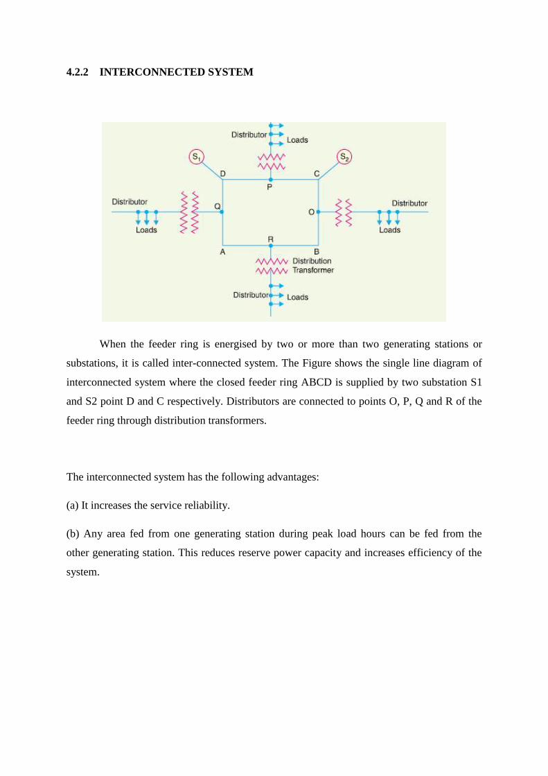
4.2.2 INTERCONNECTED SYSTEM
When the feeder ring is energised by two or more than two generating stations or
substations, it is called inter-connected system. The Figure shows the single line diagram of
interconnected system where the closed feeder ring ABCD is supplied by two substation S1
and S2 point D and C respectively. Distributors are connected to points O, P, Q and R of the
feeder ring through distribution transformers.
The interconnected system has the following advantages:
(a) It increases the service reliability.
(b) Any area fed from one generating station during peak load hours can be fed from the
other generating station. This reduces reserve power capacity and increases efficiency of the
system.

4.2.3 RADIAL DISTRIBUTION SYSTEM
A representative schematic of a radial distribution system is shown in figure 4-1. You
should note that the independent feeders branch out to several distribution centers without
intermediate connections between feeders.
Figure 4-2 Radial distribution system.
The most frequently used system is the radial distribution system because it is the
simplest and least expensive system to build. Operation and expansion are simple. It is not as
reliable as most systems unless quality components are used. The fault or loss of a cable,
primary supply, or transformer will result in an outage on all loads served by the feeder.
Furthermore, electrical service is interrupted when any piece of service equipment must be
de-energized to perform routine maintenance and service.
Service on this type of feeder can be improved by installing automatic circuit breakers
that will reclose the service at predetermined intervals. If the fault continues after a
predetermined number of closures, the breaker will lock out until the fault is cleared and
service is restored by hand reset.

4.3 Distribution Network System In Malaysia
National Grid System
Primary electricity transmission network linking the electricity generation,
transmission, distribution and consumption in Malaysia. It operated and owned by TNB. It
have more than 420 substation in Peninsular Malaysia are linked together by the extensive
network of transmission lines operating at 132kV, 275kV and 500kV.
Power generated by TNB and IPP is carried by the National Grid towards customers
connected to the various distribution networks. The electrically interconnected to the
transmission network of the Electricity Generating Authority of Thailand (EGAT) and also to
Singapore Power.
4.3.1 Advantages of national grid system
a) Provide multiple paths between various generation sources and loads
b) Provide for power transfers from one geographic area to another to achieve overall
system operating economics.
c) Interconnect the bulk power facilities of individual power station/utilities so that they
can better withstand major disturbances.
d) Cheap and efficient

Figure 1: National Grid System in Peninsular Malaysia

Figure 2: Grid System in Sabah
Figure 3: Grid System in Sarawak

5.0 CONCLUSION
Distribution layout is very important in design in electrical system. In Malaysia, we
use National Grid, Malaysia (Malay: Grid Nasional). It is the high-voltage electric power
transmission network in Peninsular Malaysia. It is operated and owned by Tenaga Nasional
Berhad (TNB) by its Transmission Division. There are two other electrical grids in Sabah and
Sarawak operated by Sabah Electricity Sdn Bhd and Sarawak Electricity Supply
Corporation respectively. The system spans the whole of Peninsular Malaysia, connecting
electricity generation stations owned by TNB and Independent Power Producers (IPPs) to
energy consumers. A small number of consumers, mainly steel mills and shopping malls also
take power directly from the National Grid.
The distribution substation receives power from one or more transmission or sub
transmission lines at the corresponding transmission or sub transmission voltage level and
provides that power to one or more distribution feeders that originate in the substation and
comprise the primary network. Most feeders emanate radically from the substation to supply
the load. There is the main component in distribution layout, which is substation, distribution
feeder circuit, switches, protective equipment, distribution transformers, secondary and
services. There are five main functions of the distribution substation, Voltage transformation,
Switching and protection, Voltage regulation and Metering. Most distribution substations
carry between 5 and 60 MVA. In Malaysia, Distribution lines of 33 kV, 22 kV, 11 kV, 6.6
kV and 400/230 volt in the Malaysia distribution network connect to the National Grid via
transmission substations where voltages are stepped down by transformers.

The distribution substation consist of Distribution Intakes (33kV, 22kV). Distribution
Substations (22kV, 11kV, 6.6kV). Which is Indoor substation, Outdoor substation, Pole
mounted substation, Compact substation and Underground substation. The transformer
capacity will be 100kVA, 300kVA, 500kVA, 750kVA and 1000kVA.
Distribution intake.

Indoor Sub-station
Underground substation

Compact substation
Outdoor Sub-station

Pole-Mounted Sub-station
Number of consumer used
The advantages of national grid system is to provide multiple paths between various
generation sources and loads, to provide for power transfers from one geographic area to
another to achieve overall system operating economics, Interconnect the bulk power facilities

of individual power station/utilities so that they can better withstand major disturbances.
Other advantages is Stability ( Load sharing ) , Continuity of service ,Maintenance,
breakdown ,Economy , Cheap and efficient