production avt development: lotus and eaton’s...
TRANSCRIPT

J.W.G. Turner and S.A. KenchingtonLotus Engineering, Norwich, UK
D.A. StretchEaton Automotive, Southfield, Michigan, USA
Production AVT Development: Lotus and Eaton's ElectrohydraulicClosed-Loop Fully Variable Valve Train System
Entwicklung eines Serien-AVT-Systems: Lotus’ und Eatonselektrohydraulischer voll variabler Ventiltrieb (AVT)
1. Introduction
Lotus and Eaton are collaborating to bring a production closed loop control FullyVariable Valve Timing system, known as Active Valve Train (AVT), to market in the2008-9 timeframe. The system uses electrohydraulic operation, movement of theengine poppet valves being initiated by oil flow into and out of a hydraulic chamberwhich is controlled by fast acting electrohydraulic servo valves developed by the twocompanies. This in turn allows infinitely variable timing, duration and lift.
The system, which is currently being engineered in prototype form for an OEM, willallow ready application of many advanced engine control strategies, such as throttlelessoperation, Controlled Auto Ignition (or Homogeneous Charge Compression Ignition),fast start, variable firing order, differential cylinder loading and ultimately airhybridisation. However, to gain acceptance in the marketplace, the two partnersunderstand that productionisation must not come at the expense of high Bill OfMaterials cost, and in controlling that requirement, the performance of the system mustnot be allowed to suffer.
This paper relates the present developmental status of the system from a valve controlstandpoint and describes some of the design features which have been adopted to fulfilthe above requirements. An estimate of BOM costs for a typical light duty automotiveapplication is also given.
1. Vorwort
Lotus und Eaton entwickeln zusammen einen voll variablen Ventiltrieb, auch ’activevalve train’ oder AVT genannt, der etwa 2008 / 2009 Serienreife haben wird. DasSystem verfügt über einen ’closed loop Controller’ und benutzt eine Elektrohydraulik,die die Bewegung der Ventile durch Ölfluss steuert. Der Ölfluss in und aus derHydraulikkammer wird durch schnell schaltende elektrohydraulische Servoventilekontrolliert, die Lotus und Eaton miteinander entwickelt haben. Hierdurch werden einvariabler Ventilhub sowie variable Öffnungszeiten ermöglicht.
Das System, das sich derzeit im Prototypenstadium befindet und für einen großenFahrzeughersteller entwickelt wird, wird die Applikation von vielen unterschiedlichenSteuerungsstrategien wie Motoren ohne Drosselklappe, HCCI, CAI, variable Zündfolge,gesteuerter zylinderspezifischer Mitteldruck und Luftdruck-Hybridisation ermöglichen.Um jedoch eine hohe Marktakzeptanz zu erreichen, muss das System nicht nur

technisch, sondern auch wirtschaftlich machbar sein. Beide Entwicklungspartnerverstehen diesen Zielkonflikt und entwickeln ein System, dass beide Seitengleichermaßen berücksichtigt.
In diesem Paper werden der derzeitige Entwicklungsstatus des AVT Systems, dieStrategie der Ventilkontrolle sowie einige Entwicklungsmerkmale dargestellt, die dazudienen, die oben genannten Forderungen zu erfüllen. Eine Abschätzung der Kostendes Systems am Beispiel eines kleinen Nutzfahrzeugdieselmotors beschließen diePräsentation.
2. The Benefits and Drivers leading to the Choice of a Fully VariableValve Train System
There are many theoretical advantages to having continuous control over the threebasic dimensions governing intake and exhaust valve events in poppet valve four-strokeengines. Variation of valve opening point, valve closing point and valve lift directlyeffects the gas exchange process, so that the pumping losses and, in somecircumstances, the combustion timing of the engine are affected [1,2]. Together with avariable intake system, the correct intake valve closing point (IVC) can lead tosignificant increases in full load torque in addition to the part load improvements whichhave been observed [3]. Optimising exhaust valve opening (EVO) can lead toincreased expansion and therefore improved efficiency, and varying exhaust valveclosure (EVC) directly controls the amount of exhaust gas trapped inside the cylinderand can therefore have a major effect on NOx emissions.
At present, the only variable valve train capable of varying the intake valve openingduration continuously between limits is BMW’s “Valvetronic” mechanism, which alsorequires an inlet cam phasing device to realise the full benefits of Miller Cycle Early InletValve Closure operation (EIVC). Other cam switching mechanisms exist which providea degree of these EIVC benefits, such as the INA switching tappet [5], manufacturedunder licence from Lotus, and Honda’s V-Tec mechanisms [6].
One common trait shared by all of these Mechanically Variable Valve Trains is that, foreach extra level of flexibility, another degree of complication is unavoidable. This isillustrated in Figure 1, which shows an oscillating cam mechanism with the samefunctionality as Valvetronic, but which is clearly far more complicated than the simpledirect acting cam profile switching tappet arrangement embodied by the Lotus-INAmechanism also shown. Both of these devices also need intake cam phasing to realisepart load reductions in pumping losses.
Given that completely flexible control of valve events is a very desirable concept from athermodynamic and engine control standpoint, and that a purely mechanical systemwould be inordinately complex (if indeed possible to arrange), one has to look to otheractuating media to obtain the desired functionality. Coupled to this, the cost ofdevelopment and manufacture of purely-mechanical systems is likely to increase fordiminishing returns, whereas a Fully Variable Valve Train is likely to become cheaper astake-up is increased. Hence Lotus and Eaton, in the production AVT project, have setout to develop a practical, cost-effective FVVT system.

Fig. 1: Lotus “Oscillating Cam” Early Inlet Valve Closure Mechanism (left) andLotus-INA “Cam Profile Switching” Coaxial Tappet (right) [Courtesy INA-Schaeffler KG]Bild 1: Lotus “Schwenknocken” frihe einlass Ventil schliessen Einrichtung (Links) undLotus-INA “Nocken Profil Schaltend” koaxialen Nocke (Rechts) [Bedankum zum INA-
Schaeffler KG]
2.1 Production AVT System Selection Considerations
Lotus is a pioneer in the engineering of fast-acting electrohydraulic systems and hasover 25 years experience of developing them. It was the first manufacturer in Formula 1racing to win a race with an Active Suspension car (Figure 2). Since then, Lotus’Control Systems department has engineered many “Active” systems, including Anti-Noise and Active Rear-Wheel Steer. Where high force authority is required, hydraulicshave generally been the preferred actuating medium, but the selection of actuationpower source for a Fully Variable Valve Train system was not automatically madefavouring hydraulics.
Fig. 2: Lotus Active Suspension F1 CarBild 2: Lotus ablauffährig Aufhängung F1 Auto
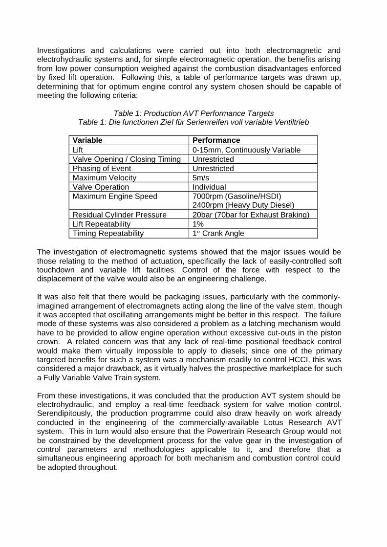
Investigations and calculations were carried out into both electromagnetic andelectrohydraulic systems and, for simple electromagnetic operation, the benefits arisingfrom low power consumption weighed against the combustion disadvantages enforcedby fixed lift operation. Following this, a table of performance targets was drawn up,determining that for optimum engine control any system chosen should be capable ofmeeting the following criteria:
Table 1: Production AVT Performance TargetsTable 1: Die functionen Ziel für Serienreifen voll variable Ventiltrieb
Variable PerformanceLift 0-15mm, Continuously VariableValve Opening / Closing Timing UnrestrictedPhasing of Event UnrestrictedMaximum Velocity 5m/sValve Operation IndividualMaximum Engine Speed 7000rpm (Gasoline/HSDI)
2400rpm (Heavy Duty Diesel)Residual Cylinder Pressure 20bar (70bar for Exhaust Braking)Lift Repeatability 1%Timing Repeatability 1° Crank Angle
The investigation of electromagnetic systems showed that the major issues would bethose relating to the method of actuation, specifically the lack of easily-controlled softtouchdown and variable lift facilities. Control of the force with respect to thedisplacement of the valve would also be an engineering challenge.
It was also felt that there would be packaging issues, particularly with the commonly-imagined arrangement of electromagnets acting along the line of the valve stem, thoughit was accepted that oscillating arrangements might be better in this respect. The failuremode of these systems was also considered a problem as a latching mechanism wouldhave to be provided to allow engine operation without excessive cut-outs in the pistoncrown. A related concern was that any lack of real-time positional feedback controlwould make them virtually impossible to apply to diesels; since one of the primarytargeted benefits for such a system was a mechanism readily to control HCCI, this wasconsidered a major drawback, as it virtually halves the prospective marketplace for sucha Fully Variable Valve Train system.
From these investigations, it was concluded that the production AVT system should beelectrohydraulic, and employ a real-time feedback system for valve motion control.Serendipitously, the production programme could also draw heavily on work alreadyconducted in the engineering of the commercially-available Lotus Research AVTsystem. This in turn would also ensure that the Powertrain Research Group would notbe constrained by the development process for the valve gear in the investigation ofcontrol parameters and methodologies applicable to it, and therefore that asimultaneous engineering approach for both mechanism and combustion control couldbe adopted throughout.

3. Production AVT System Philosophy and Design
3.1 Research AVT Baseline
Photographs of an engine fitted with the Research AVT system, which Lotus has beenproviding to clients for 13 years, are shown in Figure 3.
Fig. 3: Photographs of Research AVT System fitted to a Single Cylinder EngineBild 3: Bilde vom Forschungs AVT System auf ein einzel Zylinder Motor
The valves are hydraulically opened and closed in a desmodromic fashion; there is noreturn spring in this system. The actuator valve block with its hydraulic drillings used toachieve this is shown fitted with the 4-way servo valve in Figure 4.
Fig. 4: Valve Block of Research AVT Actuator (4-Way EHSV at Bottom,Displacement Transducer at Top Right)
Bild 4: Ventil Block vom den Forschungs AVT Bedienteil (4 Weg EHSV untern,Ablösung Sensor oben)

The 4-way electrohydraulic servo valve switches pressure to either the top or the bottomchamber (depending upon whether the valve is being commanded to open or close,respectively), simultaneously venting fluid from the bottom or top chamber. Figure 4also shows the position sensor fitted to the top of the actuator rod which feeds back inreal time to the valve control computer, allowing it in turn to alter the position of the 4-way valve to achieve the desired valve displacement for any given crank angle.
The 4-way electrohydraulic servo valve is extremely expensive, being developed forcontrolling the flow of fuel and oxidant systems in rocket engines, and so is not a viableoption for any production system. Furthermore, it does not offer sufficient speed foraccuracy at engine speeds above 4000rpm. A new approach was required which wouldsimultaneously minimise cost and markedly improve performance.
3.2 Production AVT Actuator Layout
For the production AVT programme, the hydraulic system determined to offer thefunctionality targeted in Table 1 is shown schematically in Figure 5. Immediately onecan see that the hydraulic complexity of Research AVT has been halved by the use of areturn spring. The remaining functionality of the Research AVT system’s 4-way valve isthen split into two. A ‘switching valve’ is used to direct flow either to or from ‘actuatorvalves’ (one per engine poppet valve) depending upon whether the poppet valve is tobe commanded to move open or closed.
Fig. 5: Schematic of Hydraulic Circuit of Production AVT SystemBild 5: Schema von hydraulischen AVT Kreislauf den serienreife AVT System
A typical sequence of operation from a closed position would occur thus (see alsoFigure 6): the switching valve would move to “pressure”, the actuator valves remaining
Switching Valve
Actuator Valve
Actuator with IntegralDisplacement Transducer

closed. Some controlled leakage through the actuator valves would lift the valve fromthe seat. The actuator valve would then positively open to enable a faster opening rate,and then close near to peak lift. The valve would continue to open slowly because ofthe controlled leakage mentioned above. At approximately half way through the valveevent the switching valve would move to “return” and the controlled leakage would startto allow the valve slowly to close due to the strain energy stored in the spring during theopening event. Positive opening of the actuator valve now allows the valve to closefaster. Near to the seat the actuator valve closes, and the controlled leak and reducedspring load now gives soft touch down and with it the facility to tailor valve overlap.
Fig. 6: Production AVT Control Valve Sequencing versus Crank AngleBild 6: Die Ablaufsteuerung den serienreife AVT kontrol ventil gegen den Kurbelwinkel
Valve position is controlled via a closed loop, with the position sensor being inside theactuator body: it is wrapped around the hydraulic chamber, with the target for the sensorbeing the hydraulic piston. The piston itself is not rigidly attached to the valve; instead itbutts up against the valve tip, and the whole AVT cassette can be mounted in one unitto the top of what is a cylinder head of largely conventional architecture, albeit onewithout the complication of cams and tappets and their associated components.
The return spring brings other significant advantages, as well as providing aconventional cylinder head arrangement and assembly procedure. When the engine isswitched off, setting all of the control valves to “return” ensures that the poppet valvespark on their seats (cf. the electromagnetic systems needing an additional lockingmechanism to achieve this, otherwise having to park half-open). This means that atstart up the system automatically has a baseline, and during start procedures the valvescan be held closed if required to allow the crankshaft to spin to a higher speed beforeallowing the admission of air. Parking closed also means that SHED test results arelikely to improve, there now being no leakage path from intake to exhaust system forbackflow of uncatalysed exhaust gases. Finally, the reduction in closing force near tothe seat means that soft seating is easier to arrange.

It was decided very early on in the programme that the system would not be engineeredto attempt to reproduce polynomial valve profiles, as these are only a function of thelimitations of a spring system being operated by a mechanical cam. Instead it wasintended to provide trapezoidal profiles with an opening and closing ramp of minimumfixed rate, and opening and closing flanks of variable velocity up to the target maximumof 5m/s. Clearly, the amount of valve lift is variable as well. All of this will allow controlof touchdown, overlap, duration and time-area to suit an engine’s mechanical andairflow requirements within the limitations of the system.
3.3 Balance of System
A complete AVT system is shown schematically in Figure 7, which represents thehydraulic circuit of a 4-cylinder, 16 valve engine.
Fig. 7: Hydraulic System Schematic for 4-Cylinder, 16 Valve EngineBild 7: Das Schema den hydraulische System für 4 Zylinder, 16 Ventile Motor
The pump is a variable displacement unit supplied by Eaton-Vickers, a subsidiary ofEaton Automotive, and is shown in Figure 8. Since (to a first degree of approximation)the power necessary to drive the valves is linearly proportional to the lift demanded, andthe pump will never pressurise more fluid than required to a pressure greater thanrequired, substantial savings in hydraulic drive power can be expected at light load.This is discussed in more detail later in this paper.
Fig. 8: Variable Displacement Pump supplied by Eaton-VickersBild 8: Variable Verschiebepumpe von Eaton-Vickers

The remaining hardware comprises flow lines, accumulators and attenuators, togetherwith a cooler and possibly a heater for low temperature operation. This may or may notbe necessary as, firstly, flowing hydraulic fluid through orifices, even at low rates,generates significant heat, and, secondly, the coils in the control valves could briefly beused as heaters to enable a better start.
The cassette-type construction of the hydraulic valve drive mechanism (which will bebolted to the cylinder head and could possibly be provided as an assembly with it),means that the number of potential leakage paths has been minimised. The onlymoving seal is that running against the actuating piston, because, unlike the researchsystem, there is no need to have the positional feedback sensor on the end of the valve(Figure 4).
Mock-ups of the system suggest that the package of an engine with Production AVTcould be reduced in size; additionally, the valves could be placed at an angle so thatlowering the overall engine height, and with it increasing the clearance to the bonnet, isalso a possibility.
Currently the actuators are at an advanced state of prototype development, ready forfitment to a cylinder head for rig and engine testing for an OEM.
The hydraulic oil system is designed to be completely separate from the crankcaselubrication system, but the oil is compatible with existing engine oil should anycrossover occur. In the long term it is envisaged that the formulation of crankcase oilsfor engines with this type of valve gear could be modified, as there will no longer be anyneed to have friction modifiers commonly associated with cam-to-tappet pressureresistance, etc. present in current oil blends.
3.4 Modelling for Performance and Power Consumption
In order to develop the control strategy, and to assess the impact of design changes onsystem performance, a Simulink model was built utilising control algorithms developedand used on the Research AVT system. In addition to establishing whether the systemwould meet its target performance, this modelling work allowed estimates to be made ofthe degree of phase advance necessary for the switching and actuator valves to obtainthe desired valve motion.
The Simulink model allowed initial estimates of power consumption to be made. Thiswas found to be in the order of 5.5kW at 6000rpm crankshaft speed for a conventionalEuropean-type 2 litre 16 valve engine, running full-lift valve events for maximum power.This is obviously a high amount (piston friction might be expected to be about 6.5kWhere), and would be expected to reduce for the lower lift values needed at part load.Further reductions in power consumption can be expected with reduced systempressure at low engine speed and valve lift rates, and valve deactivation (on the inlet orexhaust) or skip-firing operation in some areas of the operating map. Further benefitswould accrue on pressure charged downsized engines, which would seek to reduce thenumber of cylinders for a given power output, and hence the number of engine poppetvalves and the total hydraulic flow rate.

For the typical range of valve lifts and number of cycles per second of the engine typestargeted for this technology, oil flow rates of 20 litres per minute for the actuator valveand 40 litres per minute for the switching valve will be required.
3.5 Control Valve Detail Design
With the philosophy decided upon and the initial control valve modelling complete, detaildesign of the control valves could begin.
Lotus’ initial intention was not to perform the detail design of the hydraulic control valvesitself. However, a study of available products from existing manufacturers, anddiscussions with most of them, revealed that nothing was commercially available thatmet the demanding requirements in terms of overall flow capacity and frequencyresponse. Consequently Lotus has had to carry out initial design and testing itself.
A CAD representation and photograph of a sub-module for the inlet or exhaust valve isshown in Figure 9. The switching valve can be seen to the left in each picture and thetwo actuator valves are above the actuator pistons which would in turn be above thevalve stems. The feed and return galleries are visible in the right-hand CADrepresentation, communicating with the switching valve.
Fig. 9: CAD Models and Photograph of AVT Sub-Module forInlet or Exhaust Valves of a Single Cylinder
Bild 9: CAD Modelle und ein Bild den AVT Baugruppe fürEinlass oder Auslaß Ventile vom ein Zylinder

These modules are in the final stages of prototype development prior to fitment to anOEM’s engine cylinder head for rig testing and then on an engine for fired testing.
4. Rig Testing and System Power Consumption
4.1 Actuator Rig Testing
Rig testing has been conducted throughout the actuator development programme togauge the actuators’ response to input commands [7]. This has been carried out on adedicated rig. The current performance of the latest level of development is shown inFigure 10.
0
2
4
6
8
10
12
14
16
90 180 270 360 450
Crank Angle (°)
Valve Lift (mm)
0
Fig. 10: Performance of Production AVT Actuators: 1000rpm, 140bar System PressureBild 10: Die functionen den Serienreife AVT Ablösungen:
1000rpm, 140bar System druck
From this rig work, knowledge of oil flow paths and the Matlab Simulink modellingdiscussed above, estimates of hydraulic power for a 4-cylinder, 16 valve engine hasbeen derived (Figure 11). These are shown for different system pressures which wouldcorrespond to different engine operating conditions; they reveal that whereas valve lift(and hence hydraulic oil flowrate) is a major driver on system power consumption, therate of valve lift is also a driver (as it affects the system pressure and hence the flowlosses through the system).
This estimation has been conducted with the assumption that all of the valves operateall of the time, and so represents something of a worst case, since valve deactivation,skip firing, single exhaust valve operation at light load etc., could be expected to yieldfurther benefits. Regardless of this, it does compare favourably with published data onpower consumption for electromagnetic systems [9], suggesting that 0.8kW per valvemay be needed for electromagnetic actuation for a ‘low power consumption’

configuration – i.e. 12.8kW in total for a 16 valve engine, far in excess of what might beexpected for the piston friction of such an engine.
Figure 11(a) clearly shows that if valve lift can be held to a minimum the powerconsumption will be very low at light load.
Fig. 11(a): Predicted AVT RMS Power Consumption for 4-Cylinder 16 Valve Engine -50bar System Pressure [Low Engine Speed, Low Rate of Rise for Valve Lift]
Bild 11(a): Ervatate RMS leistungs Verbrauch den AVT System von 4 Zylinder16 Ventile Motor – 50bar druck [neidrige Motoren drehzahl,
neidrige Geschwindigkeit für Ventilerhebung]
Fig. 11(b): Predicted AVT RMS Power Consumption for 4-Cylinder 16 Valve Engine -100bar System Pressure [Full Map Operation, Intermediate Rate of Rise for Valve Lift]
Bild 11(b): Ervatate RMS leistungs Verbrauch den AVT System von 4 Zylinder16 Ventile Motor – 100bar druck [voll Motorkennfeld,
dazwischen Geschwindigkeit für Ventilerhebung]

Fig. 11(c): Predicted AVT RMS Power Consumption for 4-Cylinder 16 Valve Engine -120bar System Pressure [High Engine Speed, High Rate of Rise for Valve High Lift]
Bild 11(c): Ervatate RMS leistungs Verbrauch den AVT System von 4 Zylinder16 Ventile Motor – 120bar druck [hochturiger Motor,
schnell gschwindigkeit für Ventilerhebung]
4.2 Supporting Engine Work
In parallel with the work to design the actuator valves, Lotus’ Powertrain ResearchGroup has conducted work into engine control with trapezoidal valve events on a sparkignition engine. Engine modelling work for full load operation to support this hadalready been conducted [8]. The intention of this dynamometer-based work was toprovide an initial study into the minimum amount of valve lift necessary to provide agiven load, as valve lift is the most important driver on hydraulic power consumption fora given engine speed and number of valves.
This is clearly an enormous task because of the number of variables to be controlled. Itwas decided to limit test speeds from 1500 to 3500rpm in 500rpm steps, and toapproach the test work with the limitation of spark ignition only (i.e. not to investigateControlled Auto Ignition yet) and of fixed exhaust closure and intake opening timing (i.e.constant overlap). Furthermore, the exhaust and intake valves both operated as pairs,and the exhaust lift was held to inlet lift minus 0.25mm.
For each engine speed, lifts were tested at 1mm increments for the inlet valves, fuellingwas fixed at 14:1 Air-Fuel Ratio (UEGO), and ignition was set to MBT or Border LineDetonation timing, whichever occurred first. The test fuel was standard 95RONUnleaded Gasoline. The flank duration was fixed at 80° for each test speed, giving amaximum velocity of 2.1m/s for 3500rpm. Results at 1500rpm and 3500rpm arepresented in Figure 12.

0
1
2
3
4
5
6
7
8
9
10
11
12
13
0 1 2 3 4 5 6 7 8 9
Valve Lift (mm)
Mea
n E
ffec
tive
Pre
ssur
e (b
ar)
0
400
800
1200
1600
2000
2400
To
tal A
ng
le A
rea
(deg
.cm
2 )
1500rpm NMEP1500rpm IMEP3500rpm NMEP3500rpm IMEPInlet Angle AreaExhaust Angle Area
Fig. 12: Mean Effective Pressures and Angle Areas versus Lift at 1500rpm and3500rpm using Trapezoidal Valve Profiles
Bild 12: Mittlere Arbeitsdruck under Arbeitbereichwinkeln gegen Ventilerhebung aus1500rpm und 3500rpm benutzend trapezoid Ventil Profile
Immediately apparent is the low level of lift necessary to achieve a high level of brakemean effective pressure at low engine speed. This is to be expected, but the keyconclusion to be drawn from this is that hydraulic power consumption for the AVTsystem can be arranged to be extremely low and is likely to be exceeded by enginepumping at light loads. It is entirely likely that, with optimisation, system powerconsumption could approach or be less than that of a mechanical camshaft system inthe drive-cycle area of operation.
Finally the system, as specified at present, incorporates no power recovery facility.Once in production, investigations will be conducted to incorporate some means ofachieving this to the primary benefit of reduced high load power consumption.
5. System Cost
5.1 Bill-Of-Materials Estimation
The performance, reliability and power consumption characteristics of the AVT systemmust be balanced by a degree of production feasibility, chiefly in the area of Bill OfMaterials (BOM) cost. An initial estimate is presented in Table 2, below.
Table 2: Estimate of On-Cost for AVT on In-Line 4-Cylinder 16 Valve Light Duty EngineTable 2: Eine Abschätzung der Kosten des Systems auf eine 4 Zylinder 16 Ventile eines
kleinen Nutzfahrzeugmotors
Actuation Modules $ 450Hydraulic System $ 475Electrical System $ 65Electronics System $ 250(not supplied by Eaton, OEM directed)Total $1245

This is on-cost for an In-Line 4-cylinder 16 valve application, and does not includesavings due to deletion of camshafts and their drive system, the associated machiningand assembly, and further savings due to smaller numbers of base enginecombinations, reduced assembly line lengths, and extra potential savings throughprocuring the entire cylinder head as one pre-tested assembly delivered just-in-time tothe production line.
It should be noted that at present this does not compare very favourably to publishedestimates for an equivalent electromagnetic system which has less functionality (novariable lift capability) [10]. However, the deletion of components is significant, andthere are other savings to be made as suggested above.
It is expected that some engine types – heavy-duty diesel, for example – will be the firstto adopt this type of technology, and that further take-up may be expected as a result inrelated fields – i.e. light-duty diesel. Homogeneous Charge Compression Ignition, andits relevance in the area of emissions control, may be a significant driver on this [11].From this base, high-value-added four-stroke gasoline might be expected to follow, andthe ‘trickle-down’ effect may then be expected to lead to greater numbers of gasolineengines adopting the technology. This will be enabled by both volume andtechnological advances driving the cost down. At present it would be over optimistic tosee an immediate and large scale uptake in gasoline engines.
A significant driver on market acceptance could be Air Hybridisation, i.e. operating theengine as an air compressor under braking to store energy in a receiver which can beutilised later by running the engine as an air motor [8,12]. This is afforded by FullyVariable Valve Trains and has the potential to offer significant fuel consumptionimprovements without the mass or complication of an electric hybrid system. Such asystem might offer cost advantages as well, while allowing the efficiency of the heatengine itself to improve through the presence of the Fully Variable Valve Train.
6. Conclusions
6.1 Lotus and Eaton are collaborating to bring AVT, a Fully Variable Valve Train, tothe market, offering packaging and fuel consumption benefits over conventionalcamshaft-driven valve actuation mechanisms.
6.2 Improved combustion control and reduced parasitic loss due to the combination ofvariable lift and a variable displacement pump will be possible with AVT.
6.3 Estimated power consumption for the AVT system may be significantly lower thansome estimates of power consumption for electromagnetic valve trains.
6.4 BOM on-cost for the system is expected to be in the region of $1245 per enginefor an In-Line 4-cylinder 16 valve engine. This does not include deletions of thecamshafts, their drives, etc., and is expected to fall as the technology is taken upand develops further.
6.5 Production AVT could enable Air Hybridisation, which would allow regenerativebraking in a vehicle, and hence fuel consumption improvement, without recourse
to an electric hybridisation system. This functionality would be in addition to thecombustion efficiency improvements which having a Fully Variable Valve Train onthe engine would also bring.
References
1. Turner J., Blundell B., Bassett M., Pearson R. and Chen R., “The Impact onEngine Performance of Controlled Auto Ignition versus Spark Ignition with TwoMethods of Load Control”, Global Powertrain Congress, 2002
2. Allen J. and Law D., “Variable Valve Actuated Controlled Auto-Ignition: SpeedLoad Maps and Strategic Regimes of Operation”, SAE Paper Number 2002-01-0422, 2002.
3. Hofmann R., Borgmann K., Liebl J. and Hall W., “The new BMW 8-cylinderpowertrains”. 10th Aachener Kolloquium und Motortechnik, 2001.
4. Schausberger C., Bachmann P., Borgmann K., Hofmann R. and Liebl J., “The newBMW Otto Engine Generation“. 10th Aachener Kolloquium und Motortechnik,2001.
5. Brüstle C. and Schwarzenthal D., “VarioCam Plus – A highlight of the Porsche911 turbo engine”. SAE Paper No. 2001-01-0245, 2001.
6. Hosaka T. and Hamazaki M., “Development of the variable valve timing and lift(VTEC) engine for Honda NSX.” SAE Paper No. 910008, 1991.
7. Allen J. and Law D., “Production Electro-Hydraulic Variable Valve-Train for a newGeneration of I.C. Engines.” SAE Paper No. 2002-01-1109, 2002.
8. Turner J.W.G., Bassett M.D., Pearson R.J., Pitcher G. and Douglas K.J., “NewOperating Strategies afforded by Fully Variable Valve Trains”. SAE Paper No.2004-01-1386, 2004.
9. Pontoppidan M., Gaviani G., Bella G., Schilardi M. and Rocco V., “EnhancedMixture Preparation Approach for Lean Stratified SI-Combustion by a CombinedUse of GDI and Electronically Controlled Valve-Timing”. SAE Paper No. 2000-01-0532, 2000.
10. Hofbauer, P., “Variable Valve Actuation: New Issues, Solutions and Technology”,Presentation at the California Air Resources Board International VehicleTechnology Symposium, Sacramento, March 2003.
11. Duret, P., Gatellier, B., Miche, M., Monteiro, L., Zima, P., Maroteaux, D., Blundell,D., Ganser, M., Zhao, H., Perotti, M., Araneo, L., “Innovative Diesel HCCICombustion Process for Passenger Cars: the European SPACE LIGHT Project”.EAEC Congress, Paris, June 2003.
12. Tai C., Tsao T.-C., Levin M.B., Barta G. and Schechter M.M., “Using CamlessValvetrain for Air Hybrid Optimization”, SAE Paper Number 2003-01-0038, 2003.