product informationproduct … solarbayer-gasifying log burner 1. sizing the boiler please note that...
TRANSCRIPT

PRODUCT INFORMATIONPRODUCT INFORMATION
Technical Hand Book
We design for your future
SOLARBAYER-BOILER

2 Solarbayer-Gasifying Log Burner
Welcome among the log wood heaters
Thank you for choosing a Solarbayer product.Your Solarbayer-gasifying log wood burner is a proven and innovative heating unit that can bepurchased in different alternatives in benefits Therefore, the log wood burner can be adjusted tothe particular heating situation. The log wood burner is easy to handle and after a few days ofusage you will fully be accustomed with it.
This product information is arranged in such a way that the most important elements are quickand easy to find and detect. It is necessary that you carefully read this handbook before the firstusage.
We hope that you will enjoy your new boiler. Feel free to contact us if you have any questions orhelpful suggestions to our products.
Now that you have purchased a log wood boiler you have to know a lot about wood itself there-fore we would like to introduce you to the secrets of perfect log wood heating.
It is important to use only untreated wood for combustion, no wood with colour, no wood withtransparent coating, no wood with chemical binders - just neither wood-fibre boards nor compressed fibreboards.
You have to be aware of the fact that only absolutely dry wood can be combusted in an ecolo-gically compatible and effective way.
The moisture percentage of wood is an essential criterion. A moisture percentage of 20% is theupper limit. Wood needs time to season. Weather the split logs under a roof and pay attentionto the fact that the wind can circulate through the wood piles.
The Solarbayer log wood boiler can be filled most effectively when your wood is split to a lengthof 50-100m (depending on the boiler size) and an edge length of 10 cm.
Birch, beech, pine, fir and spruce wood timber need at least 2 years of seasoning under ideal conditions (consolidated under a roof).
Oak and robinia instead need at least 3 years of seasoning. Split timbers of oak trees should bestored outside during the first year of seasoning before consolidating. Oak and robinia are onlyto be combusted in combination with coniferous wood.
If the remaining humidity is too high the heat output is clearly diminished and leads to an in-creasing excess of tar which condenses at the boilers’ walls and leads to the sooting of the chim-ney.
In case of doubt use a moisture meter.
The combustion of beech wood is long-lasting and clean. A stacked cubic metre with a moisturepercentage of less than 20% replaces approximately 190 litres of fuel oil. 1 stacked cubic metreof coniferous wood, e.g. fir, can replace approx. 135 litres of fuel oil.
If you have chosen your Solarbayer log wood burner according to your energy needs and if youuse it as exclusive heating system you should provide yourself with approx. 2 stacked cubic metres of wood per calculated kW. (calculated heat output of approx. 10 kW => 20 stacked cubicmetres of wood).

Solarbayer-Gasifying Log Burner 3
1 ControlSimple controller for efficient burncycle
2 Large fuel chamber door3 Forced draught fan
A variable speed motor supplies the air needed for the gasification process in the burner.
4 Bottom doorEasy access to bottom of the burner for cleaning
5 Fuel chamberFor logs sizes from 50 cm up to 100 cm (depending on model)
6 Primary air ductDue to the air channel at the back,pre heated air is added to achieveclean combustion.
7 Ceramic nozzle with secondary air ductBrings about the right air to gas mix, which creates the best possible flame
8 Combustion chamber Made of high temperatureresistant fireclay bricks, tocomplete gasification pro-cess which results in mini-mal amount of ashes
9 Ash chamber10 Exhaust gas heat
exchangerFor best energy transfer tothe heating system
11 DamperTo be used when lighting up the burner (Draft Regulation)
12 Safety Heat ExchangerWill cool down burner incase of overheating
13 Flow14 Return15 Chimney flap
Upper Fire Box Gasification at the jet in theLower Chamber
15
1
2
13
3
4
5
12
11
10
14
7
8
6
9
Inside the burner
7
1

4 Solarbayer-Gasifying Log Burner
Contents 1 Sizing your Boiler 6
2 General Information SOLARBAYER boiler2.1 Technical Description 72.2 Construction 72.3 Technical Details 82.4 Dimensions 92.5 Boiler Diagram 9
3 Safety Regulations3.1 Mounting and Setup 103.2 Safety Measures - Fire Protection 103.3 Safety Instruction for Operation and Maintenance 11
4 Additional Equipment for SOLARBAYER boiler4.1 Safety Heat Exchanger 124.2 Boiler Circuit Pump, Laddomat 144.3 Induced draught fan (optional) 15
5 Main Parts of the SOLARBAYER boiler5.1 Adjusting the Doors 175.2 Door Seal of the Fuel Chamber 185.3 Cover plates of the Boiler Body 195.4 Forced draught fan 205.5 Secondary Air Adjustment 215.6 Fireclay bricks in the Combustion and Ash Chamber 225.7 Nozzle and Linig made of Refractory Bricks 235.8 Primary and Secondary Air Ducts 235.9 Safety Temperature Limiter STB 245.10. Boiler Control Unit 245.11. Sensor Parameters 26
6 Control Menu6.1 Directions for Use 276.2 Flow Chart of the Control Unit 286.3 Presetting and Changing of Parameters 29
6.3.1 Adjusting the Boiler Temperature 306.3.2 Adjusting the Switch Off Temperature 316.3.3 Setting the Time 32
6.4 Adjustment of the SOLARBAYER-Abgastronic 336.4.1 Adjusting the Exhaust Gas Temperature 346.4.2 Adjusting the Minimum Fan Speed 356.4.3 Selecting the Burner Type 36

Solarbayer-Gasifying Log Burner 5
7 Control Unit of the SOLARBAYER boiler7.1 Factory Settings (standard settings) 37
8 Initial Operation of the SOLARBAYER boiler8.1 Heating Up the Boiler 388.2 Refuelling the Boiler 418.4 Shutting off the Boiler 428.3 Heat Value Chart / Storing of Firewood 43
9 Boiler Maintenance9.1 Cleaning the Boiler 449.2 How to Measure the Exhaust Gases 479.3 Boiler and Exhaust Gas Temperatures during Operation 48
10 Maintenance and Repair of the Boiler 49
11 Trouble Shooting 50
12 Wiring Diagrams12.1 Typical wiring diagrams without oil-fired boiler 5212.2 Typical wiring diagrams with oil/fired boiler 54
13 Technical Service13.1 Software Adjustment 5613.2 Wiring diagram 56
Warranty 58
Declaration of Conformity 59

6 Solarbayer-Gasifying Log Burner
1. Sizing the Boiler Please note that the boiler output specified can only be achieved under full load. To heat up theboiler will take approx. 30 min until full load is reached. The boiler output is kept for a period ofapprox. 2 hours, after that the burn-out phase follows with reduced output for a period of approx.1.5 hours. The residual embers in the combustion chamber coasts the temperature for aboutone more hour, after that the fuel is completely used up. Hence, the duration of the burn cycle isapprox. 4 hours.
The boiler will be heated up in the morning and in the evening, thus a burning time of approx.8 hours is achieved. Warning: This is imperative for the rating of the boiler to avoid that the boiler output is ratedtoo weak.
Rough estimate of boiler size by means of living space:Example: building with 150 m! living space
desired boiler size Solarbayer 25 kWrequired heat output per square metre living space*
Old building 0.12 kilowatt per m!
New building 0.08 kilowatt per m!
Low energy house 0.05 kilowatt per m!
Calculation of the daily output of the building e.g. living space 150 m!, e.g. new building => 0.08 kW/h per m!
150 m! x 0,08 kW/m2
= 12 kW
The hourly output for the new building with an outdoor temperature of -16°C results in 12 kW/h
Daily requirements 24 hrs x 12 kW=288 kWh
The heat output required at -16°C outdoor temperature is 288 kW per day.
Calculation of the boiler output: e.g. SOLARBAYER 25:Output 25 kW x 4 hrs (full load)
= 100 kWh
The burning-down heat output of a 25 kW solid fuel boiler at approx. 4 hrs full load results in 100kW.
Daily requirements of the new building 288 kWh : 100 kW h (burning-down heat output)= 2,88 boiler fillings
to achieve the necessary heat output of the building
With this building you must fill the boiler around 3 times per day with an outdoor temperature of-16°C. An average of 2 fillings per day should be sufficient..
This calculation is for general information only and does not replace professional design!
* If the boiler is dimensioned too small you will achieve boiler temperatures of 70 - 80°C, but the desired heating supply line temperature will not be achieved, e.g. building size 220 m2 old building: boiler output 25 kW (wrong rating!) Correct would beSOLARBAYER 50kW.
Solarbayer-Gasifying Log Burner 7
2. General Information SOLARBAYER boiler
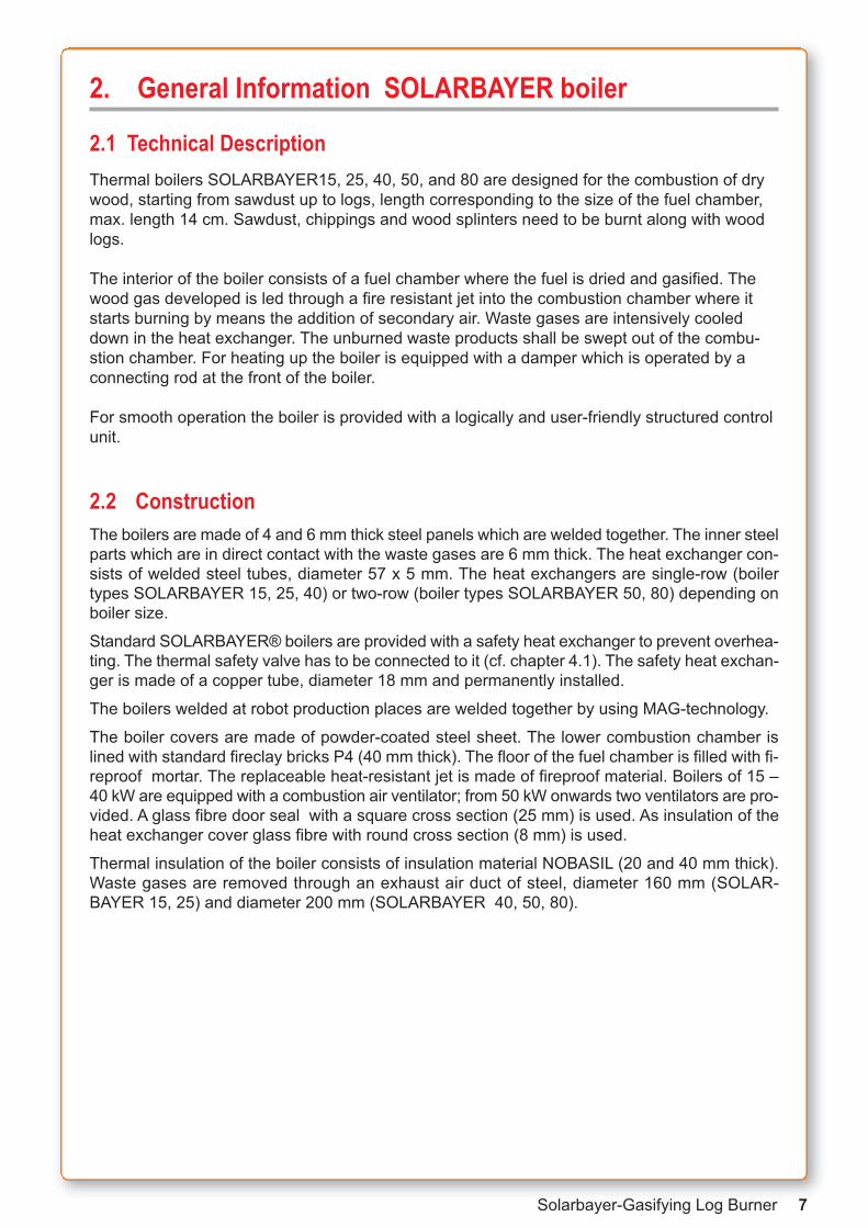
2.1 Technical DescriptionThermal boilers SOLARBAYER15, 25, 40, 50, and 80 are designed for the combustion of drywood, starting from sawdust up to logs, length corresponding to the size of the fuel chamber,max. length 14 cm. Sawdust, chippings and wood splinters need to be burnt along with woodlogs.
The interior of the boiler consists of a fuel chamber where the fuel is dried and gasified. Thewood gas developed is led through a fire resistant jet into the combustion chamber where itstarts burning by means the addition of secondary air. Waste gases are intensively cooleddown in the heat exchanger. The unburned waste products shall be swept out of the combu-stion chamber. For heating up the boiler is equipped with a damper which is operated by aconnecting rod at the front of the boiler.
For smooth operation the boiler is provided with a logically and user-friendly structured controlunit.
2.2 ConstructionThe boilers are made of 4 and 6 mm thick steel panels which are welded together. The inner steelparts which are in direct contact with the waste gases are 6 mm thick. The heat exchanger con-sists of welded steel tubes, diameter 57 x 5 mm. The heat exchangers are single-row (boilertypes SOLARBAYER 15, 25, 40) or two-row (boiler types SOLARBAYER 50, 80) depending onboiler size.
Standard SOLARBAYER® boilers are provided with a safety heat exchanger to prevent overhea-ting. The thermal safety valve has to be connected to it (cf. chapter 4.1). The safety heat exchan-ger is made of a copper tube, diameter 18 mm and permanently installed.
The boilers welded at robot production places are welded together by using MAG-technology.
The boiler covers are made of powder-coated steel sheet. The lower combustion chamber islined with standard fireclay bricks P4 (40 mm thick). The floor of the fuel chamber is filled with fi-reproof mortar. The replaceable heat-resistant jet is made of fireproof material. Boilers of 15 –40 kW are equipped with a combustion air ventilator; from 50 kW onwards two ventilators are pro-vided. A glass fibre door seal with a square cross section (25 mm) is used. As insulation of theheat exchanger cover glass fibre with round cross section (8 mm) is used.
Thermal insulation of the boiler consists of insulation material NOBASIL (20 and 40 mm thick).Waste gases are removed through an exhaust air duct of steel, diameter 160 mm (SOLAR-BAYER 15, 25) and diameter 200 mm (SOLARBAYER 40, 50, 80).
8 Solarbayer-Gasifying Log Burner
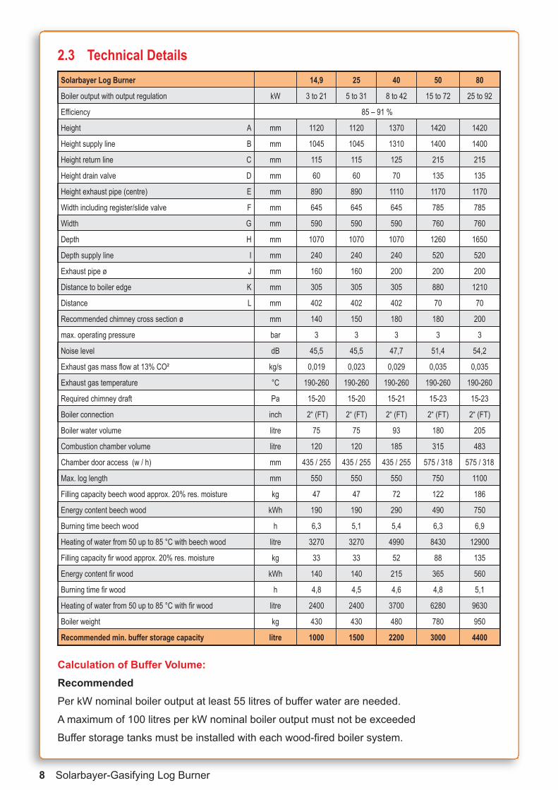
2.3 Technical Details
Calculation of Buffer Volume:Recommended Per kW nominal boiler output at least 55 litres of buffer water are needed.
A maximum of 100 litres per kW nominal boiler output must not be exceeded
Buffer storage tanks must be installed with each wood-fired boiler system.
Solarbayer Log Burner 14,9 25 40 50 80
Boiler output with output regulation kW 3 to 21 5 to 31 8 to 42 15 to 72 25 to 92
Efficiency 85 – 91 %
Height A mm 1120 1120 1370 1420 1420
Height supply line B mm 1045 1045 1310 1400 1400
Height return line C mm 115 115 125 215 215
Height drain valve D mm 60 60 70 135 135
Height exhaust pipe (centre) E mm 890 890 1110 1170 1170
Width including register/slide valve F mm 645 645 645 785 785
Width G mm 590 590 590 760 760
Depth H mm 1070 1070 1070 1260 1650
Depth supply line I mm 240 240 240 520 520
Exhaust pipe ø J mm 160 160 200 200 200
Distance to boiler edge K mm 305 305 305 880 1210
Distance L mm 402 402 402 70 70
Recommended chimney cross section ø mm 140 150 180 180 200
max. operating pressure bar 3 3 3 3 3
Noise level dB 45,5 45,5 47,7 51,4 54,2
Exhaust gas mass flow at 13% CO! kg/s 0,019 0,023 0,029 0,035 0,035
Exhaust gas temperature °C 190-260 190-260 190-260 190-260 190-260
Required chimney draft Pa 15-20 15-20 15-21 15-23 15-23
Boiler connection inch 2“ (FT) 2“ (FT) 2“ (FT) 2“ (FT) 2“ (FT)
Boiler water volume litre 75 75 93 180 205
Combustion chamber volume litre 120 120 185 315 483
Chamber door access (w / h) mm 435 / 255 435 / 255 435 / 255 575 / 318 575 / 318
Max. log length mm 550 550 550 750 1100
Filling capacity beech wood approx. 20% res. moisture kg 47 47 72 122 186
Energy content beech wood kWh 190 190 290 490 750
Burning time beech wood h 6,3 5,1 5,4 6,3 6,9
Heating of water from 50 up to 85 °C with beech wood litre 3270 3270 4990 8430 12900
Filling capacity fir wood approx. 20% res. moisture kg 33 33 52 88 135
Energy content fir wood kWh 140 140 215 365 560
Burning time fir wood h 4,8 4,5 4,6 4,8 5,1
Heating of water from 50 up to 85 °C with fir wood litre 2400 2400 3700 6280 9630
Boiler weight kg 430 430 480 780 950
Recommended min. buffer storage capacity litre 1000 1500 2200 3000 4400

Solarbayer-Gasifying Log Burner 9
2.4 DimensionsDimensions of the SOLARBAYER-Log Burner
1 Control2 Upper door3 Damper Control Rod4 Fuel Chamber5 Primary air duct6 Fan flap7 Fan8 Fan cover9 Ceramic nozzle10 Secondary air duct11 Door handle12 Refractory bricks13 Bottom door14 Chimney flap
15 Heat exchanger cover16 Damper control lid17 Upper cover (rear)18 Flow19 Thermal safety valve assembly20 Thermometer21 Upper cover (front)22 Heat exchanger pipes23 Fireproof cladding24 Secondary air duct25 Combustion chamber26 Direction of exhaust gas stream27 Return water28 Drain
2.5 Boiler DiagramSOLARBAYER 25 SOLARBAYER 40
SOLARBAYER 50-80

10 Solarbayer-Gasifying Log Burner
3 Safety Regulations
3.1 Mounting and Setup• The boiler can be only operated within a central heating system with a heat capacity corre-
sponding to the output of the boiler.
• The assembly has to be performed according to the currently asserted DIN norms and regulations
• When using forced circulation the central heating must be designed in such a way that the mi-nimum heat consumption of 5 kW of the boiler output is guaranteed in case of power failure(breakdown of shunt valve with pump - Laddomat). The pipelines to the buffer storage tankshould be installed with automatic transition into gravitation flow.
• The boiler must be connected to the chimney in a workmanlike manner and by the shortestway.
• Do not install any further heating systems to the chimney.
• Only use thermal safety valves that are tested and registered according to DIN 3440.
• The boiler must be placed on a firm, load-bearing floor.
• The minimum temperature of the return line water at the boiler inlet must be 72°C.
• The room where the boiler is installed must be ventilated by means of a permanent openingwith a diameter of at least 250 cm. Openings for air supply and air exhaust shall be around thesame size.
• The boiler must be erected in a normal room
3.2 Safety Measures - Fire protectionThe boiler shall be installed in accordance with the applicable fire protection regulations. With re-gard to installation specified safe distances from combustible and inflammable materials and ob-jects have to be observed. For thermal boilers with an output up to 50 kW the specified safedistance from combustible materials of class B, C1 and C2 must be at least 200 mm and of classC3 at least 400 mm in accordance with standard. The safe distance is reduced to half if a non-combustible thermal insulation board (asbestos board with a minimum thickness of 5 mm) is in-stalled 25 mm from protected combustible material. The board shall project at least 150 mmabove the outline of the boiler with smoke exhaust and above the upper surface of the consu-mer must be at least 300 mm free space.
Material classification:
Class A: non-combustible building materials (asbestos, concrete, mortar, brick, glass, fireclay,etc.)
Class B: very hardly combustible materials (gypsum cardboard, etc.)
Class C1: hardly combustible materials (lignite boards, chip boards in acc. with STN 492615, etc.)
Class C2: moderately combustible materials (wood – oak, alder, larch, fir, wood chip boards, etc)
Class C3: easily combustible materials (wood – pine, beech, ash, poplar, wood fibre boards,cork, foil sheets, polystyrene, polyethylene, bituminous cardboard, pulp, plywood, etc)
In case of any doubt the SOLARBAYER boiler has to be placed on a protective plate (see figurepage 11).If there are any ambiguities please contact the appropriate regulating authority (i.e. district chimney sweeper).

Solarbayer-Gasifying Log Burner 11
Sample of size of floor cover
3.3 Safety Regulations for Operation and MaintenanceThe staff operating the boiler must observe the rules and regulations and standards in connection with operation:
1. During operation of the boiler, electrical equipment and cables of the boiler must not be inter-vened with, for example:
• removal of covers of electrical systems such as boiler electronics, ventilator, thermostat
• exchange fuses
• repair of damaged cable insulations, etc..
2. Maintenance or repair work that requires removal of covers of electrical parts of the boilermust only be performed by the person entitles in accordance with publication No. 74/1996 ofthe compendium of laws.
3. Prior to removal of the covers of the boiler or an electrical device connected to the boiler it isnecessary to switch off any mains supply.
4. If defects at the electrical installation or defects at the installation of the boiler are detected itis necessary to observe the following rules:
• do not touch boiler parts
• immediately disconnect the boiler from power supply; call the responsible service engineerto solve the problem
5. Heat-resistant cable placing according to VDE standard.

4 Additional equipment for SOLARBAYER boilers
4.1 Safety heat exchangerA thermal safety valve is laid down by DIN 4751-2 for solid fuel heating system.
Use of the safety heat exchange:In case of power failure the thermal safety valve (thermostatic valve Watts STN 20)serves as boiler protection mean to prevent overheating.
Assembly of the safety heat exchanger:The boilers are already equipped with the safety heat exchangers. The thermal safety valve(thermostatic valve Watts STN 20) will be delivered separately.
Mounting of the Safety Valve STN 20:It is important, to fit the thermal safety valve in such a way, that, under operating conditions, thesafety heat exchanger is depressurised and is not connected to the pressurised part of the hea-ting system. The thermal safety valve has to be connected to the pressurised mains water line,without any means of shutting of the water supply (Stopcocks, valves, etc.). The drain side hasto be run unobstructed into a gully or drain.
Note: The thermal safety valve has to be fitted before the system is filled or put into operation.Observe local guide lines.
Function of the Safety Vale :The pressure independent valve opens whenthe flow temperature of aprox. 95 °C is reached.By opening the valve, it will cause a constantdrain of water which inhibits the temperature torise above 110 °C.
NOTE: The galvanised nipple of the safety heatexchanger is attached with a washer seal to thecopper pipes by screwing, if a water leak shalloccur between the different fittings, tighten the galvanised nipple or replace the washer seal.
SOLARBAYER-Technologie
1 Outer boiler wall2 Weld Seam3 Weld neck socket4 EPDM seal5 Threaded nipple6 Copper pipe heat exchanger 18mm
Copper Pipe sealing for the Thermaldischarge safety valve
12 Solarbayer-Gasifying Log Burner

Solarbayer-Gasifying Log Burner 13
Thermal discharge safety valve
Note:According to DIN 4751-2 pt 10 you are asked to have aninspection carried out by a suitable qualified person atleast once a year.
! thermal discharge safety valve (discharge valve Watts STN 20 "“), cold waterinput " sensor pocket with dual temperature monitor
# cold water output
Please test the thermal safety valve at first use for operation by heating up the boiler toopening temperature.
" !#
!"#
Solarbayer 25 kW and 40 kW
Solarbayer 50 kW and 80 kW

4.2 BAYER-Hinweis: Für den Betrieb des SOLARBAYER-Holzvergasers ist eine Rück-laufanhebung zwingend vorgeschrieben, um eine lange Lebensdauer zu garantieren.
Diese soll eine Kesselrücklauftemperatur von 72 °C gewährleisten. SOLARBAYER empfiehltLaddomat 21.
Elektrischer Anschluss:
Der elektrische Anschluss der Kesselkreispumpe erfolgt an der Klemmleiste der Regelungspla-tine (Anschlussbelegung siehe Schaltplan Kapitel 13.2).
Die maximale elektrische Leistungsaufnahme beträgt 200 W.
Arbeitsweise:Die Pumpe wird beim Anstellen des SOLARBAYER-Holzvergasers sofort eingeschaltet, damit derKessel gleichmäßig hochgeheizt wird.
Die Pumpe ist ausgeschaltet, wenn der Kessel aus- bzw. abgestellt ist. Wenn jedoch die Kes-seltemperatur die Solltemperatur (z.B. 85 °C) überschreitet, schaltet die Pumpe ein um eineÜberhitzung zu vermeiden.
Der Betriebsstand der Pumpe wird durch die LED-Diode auf dem Display angezeigt.
Achtung: Beim Betrieb des Kessels ohne thermische Rücklaufanhebung besteht die Gefahrder Kondensbildung und somit zur Zerstörung der Kesselwandung.
Für eine ordentliche Verbrennung ist eine Kessel-temperatur zwischen 75 und 90 °C erforderlich.Dies ist nur mit dem Laddomat zu erreichen.
Bei einer Störung/Fehlfunktion des Kesseltemperaturfühlers ist die Pumpe immer ein!
4.2 Boiler Circuit Pump, LaddomatNote: To run the boiler efficiently and to guarantee a long service live, it is important to operatethe burner with a boiler return control that ensures a return temperature of 72 °C to the burner.We recommend the Laddomat 21.
Electrical Connection:Connect the boiler circuit pump to the connection rail on the control panel (see chapter 13.2 forlayout).
Maximum load 200 W.
Function of the boiler circuit pump:Once the SOLARBAYER-log burner is switched on, the pump is activated to ensure a constantrising of the boiler temperature.
When the boiler is switched off, the pump stops. In the event that the boiler temperature exceedsthe set temperature (90 °C) the pump switches on to prevent overheating.
The operation status of the pump is shown by the LED diode on the display.
Warning: Running the boiler without a thermal re-turn control will result in the building up of conden-sation, which will lead to rapid corrosion of theboiler walls.
For a clean and efficient combustion a boiler tem-perature between 75 and 90 °C is necessary. Thiscan only be achieved with the Laddomat.
In case of a malefunction or fault of the temperature sensor, the pump switches on!
Laddomat 21 with temperature set at 72 °C
14 Solarbayer-Gasifying Log Burner
spring
piston
spring
thermostaticelement
plate forcheck valve
cover
cover check valve
to buffer tank
Laddomat
from buffer tank
expansion vessel for theboiler
safety assembly
Solarbayer Boiler14,9 kW to 80 kW

Solarbayer-Gasifying Log Burner 15
4.3 Induced draught fan (optional)The standard SOLARBAYER boiler is equipped with aforced draught fan. The electronic control enables the additional application of an indu-ced draught fan (ID fan).
The ID fan provides for the optimum removal of flue gases out of the fuel chamber during loading of fuel. Thus, noflue gas escapes out of the fuel chamber du-ring loading.
The ID fan is not included in the standard equipment of the boiler. It is available in sizes 160 mm and 200 mm as optional accessory.
The ID fan for direct attachment to the flue pipe is suitable for all boilers.
Degasing the fuel chamber with the induced draught fan
Exhaust Fan 90sboiler temp °C
!+ After pressing key “+” at the control unit, the Id fan is putinto operation for 90 seconds. After pressing the keyagain further 90 s are added, maximum running time oftheventilator is 300 s. Fuel can be refilled during the operation of the ID fan.
Warning:Do not install motor vertically!
Correctly Installed ID fan(motor horizontal)

16 Solarbayer-Gasifying Log Burner
Note for correct sizing of expansion vessel:Dimensioning of the expansion vessel (10% of heating water volume)
e.g. 2000 litre heating water = 200 litre expansion vessel.
Warning: The expansion vessels are factory-preset to 1.5 bar diaphragm pressure. It is necessarythat the vessels are adjusted to the height of your installation. Measure the installation height of yourhouse, from the basement to the topmost radiator. Example: installation height 7 metres + 2 met-res extra = 9 metres.
9 metres correspond to 0.9 bar diaphragm pressure at the expansion vessel.
The vessels need to be checked every 2 years by relieving the heating pressure and measuring ofthe diaphragm pressure. Afterwards the cold heating installation must be filled to 1.2 bar. Duringheating up the heating pressure will increase a little and drop again during cooling down.
Technical Data:The motherboard of the control unit holds ajoint for the connection of the exhaust fan(see chapter 13.2 for wiring diagram)
Technical Data Induced Draught FanMax. Temperature (°C) 600Motor Speed (1/min) 2780Output (Watt) 48Mains Supply (V/Hz) 230/50Protection IP 20Weight (kg) 13Max. Temp. Motor (°C) 80Overall length A 385 mmWidth 235 mmHeight with Motor C 247/280 mmExhaust Inlet/Outlet D 70 mmOutlet/ Inlet Diameter 160/200 mm
If the exhaust gas formation is too high while refuelling the boiler and therfore leads to unpleasant odours, we recommend the installation of an induced draught fan. The retrofitting is easy to handle. An electrical connection is pre-installed.
Solarbayer Gasifying Log Burner 1717 Solarbayer-Gasifying Log Burner
5. Main Parts of the SOLARBAYER Boiler
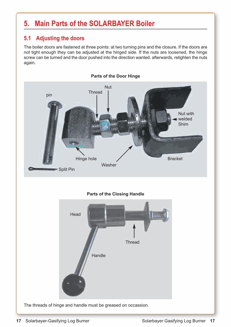
5.1 Adjusting the doorsThe boiler doors are fastened at three points: at two turning pins and the closure. If the doors arenot tight enough they can be adjusted at the hinged side. If the nuts are loosened, the hingescrew can be turned and the door pushed into the direction wanted. afterwards, retighten the nutsagain.
pin
Split Pin
Bracket
Nut with weldedShim
Hinge hole
ThreadNut
Washer
Parts of the Closing Handle
Parts of the Door Hinge
The threads of hinge and handle must be greased on occassion.
Head
Thread
Handle

18 Solarbayer Gasifying Log Burner
5.2 Door Seal on the Fuel Chamber
Attention: As the inside of the door is made of heat resistant concrete care must be taken thatthe upper door is not used to press the fuel into the boiler because this leads to damage of thelining.
Damaged lining should be removed and replaced. Adequate mortar is available at SOLARBAYER. Prepare the mortar mixture not before starting the repair work. If prepared useimmediately. The setting time of 24 hours has to be respected.
The doors, like the boiler, consist of the insu-lations and a sheet-metal covering
Adjustable hinge at the right side of the boiler Fastening plate welded on to the boiler body
Location of sealing cord joint
Replacement of thermal insulation1. Open door completely
2. Find the joint of the insulation at hinged side of the door using a screw driver.
3. Remove the hardened insulation gradually using a screw driver
4. Match the ends of the old or new sealingcord and press them in the groove bet-ween the hinged joints starting in the middle. Distribute the remainder of the insulation evenly to the sides and press ittogether in the middle.
5. If there are leakages put some heat-resistant silicone into the groove at thecorners.
6. Always start in the middle in direction of thecorners when inserting the door insulationTake care, that the insulation is not turned round and that the corners are filled well.

Solarbayer Gasifying Log Burner 19
5.3 Cover plates of boiler body The cover plates of the boiler body are made of powder-coated steel sheet and treated with firedcolour to protect the plates from corrosion. Three colours are used: grey, silver and SOLAR-BAYER-orange. Grey is used for the cover plates of the upper and lower doors, the ventilator casing is varnished with SOLARBAYER-orange and silver is used for the remaining jacket of theboiler.
The upper front plate needs to be dismantled for the entry of the thermostatic sensor. To dismantle this plate, the two self-cutting screws at the front must be loosened first. Then you remove the cover caps located at the corners of the upper front plate with a slot-head screw driver. Below the cover caps are self-cutting screws which shall only be loosened. At first, youpush the upper front plate 2 cm to the front and then you tilt it carefully from the front to the back.
Note:Prior to removal of the boiler jacket or one of the electrical devices connected to the boiler, allcables must be disconnected from the mains supply.
The side cover plates shall be dismantled as follows: At first, the upper front plate must be removed as described above. Then the upper plate at the back needs to be dismantled. Theupper and lower boiler door must be tightly locked. To dismantle the cover plate on the hingedside the nuts pressing on the galvanized shims shall be loosened. When dismantling the plateon the closure side the two screws located under the closure of the door shall be removed. Thenthe ventilator casing shall be removed. At the back side all self-cutting screws shall be removedand then the two side cover plates can be dismantled.
The door cover plates shall be dismantled as follows: at first, the entire doors shall be dismant-led in such a way that the pin can be pulled out of the hinge. The closure of the door shall be dismantled. The doors shall be laid down in such a way that the interior side lies on the floor. Thecover plate of the long sides shall be pulled out and laid down. The cover plate is only put on tothe doors.

Note: A dust free and clean environment is the basic condition for the reliable operation of theventilator. Therefore, it is necessary that the fan is regularly checked and serviced. If the noiselevel becomes more intensive, dust from the blades of the propeller should be removed. Dust onthe blades results in noisy operation and leads to decline in the technical parameters and thusto lower boiler output and worse emission values.
Prior to replacement or dismantling of the fan all power cables must be disconnected from powersupply. Then the cover plate shall be dismantled. With boiler types SOLARBAYER 40, 50, 80,100, access to the screws is easy and it is possible to remove the plate below the ventilator inorder to reach the screws.
The fans installed in boilers SOLARBAYER 15 and 25 are provided with an intake guard plateto reduce the air volume required for combustion. This guard plate can be only found in ventila-tors with metal sheet propellers. The guard plate is not necessary for plastic propellers
5.4 Forced draught fanSOLARBAYER boilers are constructed as overpressure boilers, i.e. the air volume required forcombustion is supplied by forced draught fans. Boilers, type 15 – 40, are equipped with one forced draught fan, in boiler types 50, 80 two fans are installed. The fan consists of 4 basic parts:
1. Fan casing made of aluminium alloy
2. Motor
3. Capacitor
4. Fan wheel
20 Solarbayer-Gasifying Log Burner

Solarbayer-Gasifying Log Burner 21
The fans used in the SOLARBAYER-boiler 15 and 25, are fitted with an intake protection platewhich is used to regulate the air flow, to adjust the power output.
SOLARBAYER 15 ,25, 40 ( Model 50 and 80 are equipped with two fans)
5.5 Sheet metal base for forced draught fan, ventilator damper, adjustment of secondary air
The sheet metal base for the ventilator is a plate onto which the forced draught fan is mounted.A part of this plate is provided with screws for the regulation of the secondary air volume and theventilator damper. The plate is fastened to the boiler body with self-cutting screws which are located all around the plate.
Behind the ventilator is a safety damper which protects the forced draught fan from back pressure and prevents self-ignition of the fuel in case of high chimney draught.
Note: In case of insufficient air pressure in the fuel chamber the function of the ventilator damper needs to be checked.
In order to guarantee optimum combustion in the boiler correct, adjustment of the secondary airis very important. The procedure is as follows: at first, the fastening nuts at the screws must beloosened and then the screws need to be turned clockwise by means of a slot-head screw driver all the way to the stop. Afterwards, the screws shall be turned anticlockwise in 2 – 3 turns.
Adjustment of the secondary air shall be carried out every time the sheet metal plate is placedbelow the ventilator or when the insulation beneath the plate is replaced. Small air draught canlead to incomplete combustion, high air draught to a so-called “cracking/popping inside the boiler”.
The adjustment of the secondary flow has to be carried out before first commission and,if necessary, adjusted according to the particular chimney draught conditions.
Adjustment Srews for secondary air flow
Air Flow AdjustmetPlate
Ventilator she
Ventilator sheet metal plate

22 Solarbayer-Gasifying Log Burner
5.6 Fireclay Bricks in the Combustion and Ash ChamberCombustion chamber bricks: The refractory bricks are only loosely adjusted in the
combustion chamber, as you can see beneath
Attention: the refractory bricks have to overlap the edge of the combustion chamber.If the refractory bricks are adjusted incorrectly, the fire hits the edge of the combustion chamber unopposed and might damage the steel tank prematurely.
A deformation or a melting loss of the steel tub does not affect the performance of theboiler and therefore it is not a defect.
Ash chamber bricks: To protect the boiler’s ash chamber against high heat influence andpossible damages, the Solarbayer boiler are equipped with 2 fireclay bricks (boiler type 40, 50and 80) which have to be placed underneath the combustion chamber.
While cleaning the ash chamber, the fireclay bricks have to be removed and afterwards positioned correctly again.
The ash chamber bricks as well as the combustion chamber bricks are wearingparts and have to be exchanged whenneeded. Suitable bricks are available at SOLARBAYER.
Mind the overlapping fireclays(approx. 10 mm)Position of the
combustion chamber bricksin the steel tub (example: HVS 25)

Solarbayer-Gasifying Log Burner 23
5.7 Nozzle and Lining made of Refractory ConcreteThe nozzle is a formed part of fire-resistant concrete and provides for the mixing of flue gaseswith secondary air which results in absolute combustion. The nozzle is located on a grate coo-led with water. The seat of the nozzle is lined with refractory mortar up to the height of the no-zzle edge. The service life of the nozzle is dependent on mechanical damage during putting onfuel and raking of fuel. For this reason, the nozzle is considered as consumablepart and can be replaced. The nozzle should be replaced only in case of acomplete breakdown. Cracks in the nozzle are no reason for its re-placement.
The pyramid shape makes replacement relatively easy. Ifthe nozzle is damaged, the remaining parts of the old oneneed to be removed. Afterwards, a new nozzle shall be in-stalled into the opening. Please, check if the new nozzle fitswell into the designed opening. If it does not fit exactly, theopening shall be adapted and not the nozzle. After installation ofthe nozzle the permeability of the individual holes shall be checked.
5.8 Primary and Secondary Air DuctsBy primary air ducts the supply of the necessary air volume from the ventilator into the combu-stion chamber is guaranteed. It is provided as the so-called rear air duct. The advantage isbetter heating of primary air.
When the plate below the ventilator is removed the primary and secondary air lines are acces-sible. The ducts at the edge lead the primary air, the inner ducts the lead the secondary air intothe nozzle. Primary air volume is not regulated but dependant on the ventilator type.
Rear Air Ducts
Secondary
Air
jet
secondary air channel
primary air channel

24 Solarbayer-Gasifying Log Burner
STB-safety temperature limiter
5.9 Safety Temperature Limiter STBA safety temperature limiter is connected to the control board.
In case of overheating, boiler temperature higher than 95°C, the forced draught fan is switchedoff from the connection (230V/50Hz).
Interference signal flashes.
Pressing the key displays
Pump LED flashes (is operating)
I!
!
Possibilities to unlock the STB
5.10 Boiler Control Unit SOLARBAYER boilers are always provided with Abgastronic
The control unit’s basic principle consists in temperature regulation of the heating water beingreleased by the boiler and of the exhaust gas temperature. The desired temperature is reachedby air volume control which is carried out by continuous control of the fan capacity.
The control unit consists of three electronic modules:
- the control unit with LC display, LED display and 4 keys
- the motherboard, named AK 2005 S, controls the electronic parts such as the forced draught fan, circulating pump, etc.
- SOLARBAYER Abgastronic module AK 2000 MMKT
The control unit is solidly installed in the boiler cover plate. The control board and the exhaustmodule are installed onto a 35mm DIN rail. Mains voltage exists only in module AK 2005 S, thecontrol unit with its LC display is electronically isolated from the mains voltage and supplied withsafe 9 V DC power.
Another possibility is to unlock the STB manually at the display casing. Release the black coverand press the green safety button. The boiler is ready for operation again.
Possible reasons for overheating are: - a broken boiler circuit pump- a closed valve- air in the system- maximum boiler temperature is achieved
The problems have to be solved immediately.
After cooling down to less than 90°C the STB can be unlocked again by pressing I!
E R R O RM A X . T E M P .

Solarbayer-Gasifying Log Burner 25
Control unit with display (rear and front view)
motherboardexhaust module
burner sensor
exhaust sensor
control unit (rear side)
All electric parts of the SOLARBAYER boilers are installed at the strip terminal of thecontrol board.For terminal layout see chapter 13.2 (wiring diagram)

26 Solarbayer-Gasifying Log Burner
5.11. Sensor parametersTo monitor the temperature in the burner a KTY 2000 type sensor is used. The sensor is connec-ted straight to the display (small plug).The performance of the sensor is shown in the graphbelow. ( i.e. 25 °C - 2000 Ohm)
A Solarbayer-PT 1000/600 type sensor is used to detect the exhaust gas temperature, which isconnected to the AK 2000 MMKT controller. The performance of the sensor is shown in the graphbelow. (i.e. 25 °C 1000 Ohm)
KTY 2000
boiler sensor
PT 1000 Sensor
Solarbayer-Gasifying Log Burner 27
6 Control Menu
6.1 Directions for use
!+
"-
!+
"-
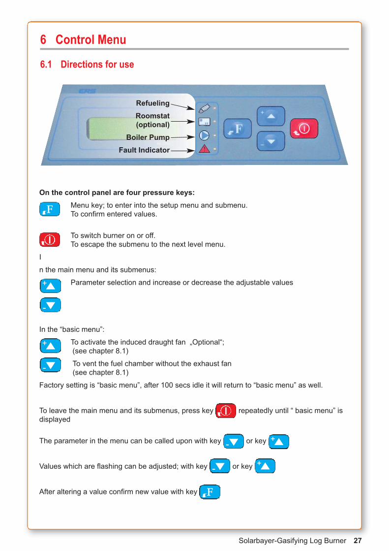
On the control panel are four pressure keys:Menu key; to enter into the setup menu and submenu.To confirm entered values.
To switch burner on or off.To escape the submenu to the next level menu.
I
n the main menu and its submenus:
Parameter selection and increase or decrease the adjustable values
In the “basic menu”:
To activate the induced draught fan „Optional“;(see chapter 8.1)
To vent the fuel chamber without the exhaust fan (see chapter 8.1)
Factory setting is “basic menu”, after 100 secs idle it will return to “basic menu” as well.
To leave the main menu and its submenus, press key repeatedly until “ basic menu” isdisplayed
The parameter in the menu can be called upon with key or key
Values which are flashing can be adjusted; with key or key
After altering a value confirm new value with key
I!
F"
F"
!+"-
!+"-
I!
RefuelingRoomstat(optional)
Boiler PumpFault Indicator

28 Solarbayer-Gasifying Log Burner
6.2 Flow Chart of the SOLARBAYER-Abgastronic control unit
Boiler offwww.solarbayer.de
Parameter: ”Heating”,”Program”,” and “Decrease” can be selected
Select with key or
Parameter “Language English”, ““Combustion wood”, “Shut down” and “Ser-vice” can be selected
Select with key or
Select parameter “Day” and “time”
Select with key or "-
"-
!+
!+
"-!+
Basic menuConfiguration
Basic menuSetting temp.
Basic menuTime setting
!+ "-
I! F"
!+ "-
„Basic Menu“
F"
F"
F"
"-

Solarbayer-Gasifying Log Burner 29
Preset Values
Parameter Factory Setting Changeable from Up toSolarbayer-
Recommended Your setting
Boiler Temperatue 85°C 65°C 90°C 90°C
Program S 1 10 (=S) S
Reducing Value 30% 20% 40% 30%Switch off Temperature(Exhaust gas temperature) 50°C 35°C 150°C 80°C
Service Settings
Exhaust Gas Temperatuer 150°C 150°C 250°C 180°C
Fan Speed 42% 3% 69% 42%
Type of Burner 0 0 1 0
Program 16 1 17 16
The Parameter values are listed and explained on the following pages.
Service data changes are carried out under Code (see chapter 6.4)
6.3 Presetting and Changing of ParametersThe burner is pre-wired, only the Laddomat-Pump of the return flow increase and the ID fanmotor have to be wired on site.
All settings are factory preset, the burner is ready for use.
Short overview of the SOLARBAYER factory settings:
Attention: The values highlighted in yellow are pre-set for systems with buffer storage tanks.
Do not alter!

30 Solarbayer-Gasifying Log Burner
6.3.1 Adjusting the Boiler TemperatureThe boiler temperature is the temperature that shall be reached and maintained in the boiler inrelation to the set exhaust gas temperature.
boiler temp.Heating 90°C
boiler temp.Heating 90°C
Basic menuSetting temp.
F"
F"
F"
F"
!+
"-
Press key
Press key
Confirm with key, display starts flashing
Press keys to adjust temperature between 65 - 90 °C
Preset = 90 °C
We recommend 90 °C
The boiler temperature is set.
In a cold boiler the permitted exhaust gas values cannot be maintained, therefore the boiler temperature has to be set between 80 and 90° C. Only with this setting an optimal combustionis possible.
Confirm with ”F” key, display stops flashing

Solarbayer-Gasifying Log Burner 31
Confirm with button. Value stops flashing.
6.3.2 Adjusting the Switch Off TemperatureThe switch off temperature defines the temperature value in the exhaust gases. The boiler willbe switched off if it falls below that value.
In the main menu press keys or until "-!+
Press or until"-!+
With the keys, up or down, select temperature from 35 - 150 °C
Preset = 80 °C
We recommend 80 °C
Switch Off Temperature is set.
ConfigurationShut down °C
F" Confirm with buttonValue starts flashing.
ConfigurationShut down °C is displayed
Basic menuSetting temp.
F" Press button
ConfigurationLanguage English
F" Press button.
Basic menuConfiguration
is displayed
F"
!+
"-

32 Solarbayer-Gasifying Log Burner
6.3.3 Setting the TimeThe date and the time can be set in the „Time Setting“ menu. Once the burner is switched on forthe first time and after a power failure the clock has to be set.
After mains supply, key flashes. After pressing the display shows error massage :
! F"
Basic menuSetting temp.
F" Press key
ERRORSLEEP
Basic menuTime setting is displayed
In the main menu press or until"-!+
Time setting10:02
F" Press key to confirm
Week day starts flashing; adjust with or
confirm with Hour setting starts flashing. Adjust hours the same way as the day andrepeatfor minutes.
Confirm each setting with
To go back in to the “ Basic Menu” press
F"
I!
F"
"-!+
Date and time have to be adjusted

Solarbayer-Gasifying Log Burner 33
6.4 Adjustment of the SOLARBAYER-AbgastronicTo change the parameters exhaust gas temperature, minimum fan speed, boiler type and the program of the SOLARBAYER-Abgastronic, go to the “password mode”. To enter it, please fol-low the steps shown below.
In the main menu press keys or until!+ "-
!+
"-press both keys simultaneously, until dislpay shows
Password settingBoiler type 0
F" press key
now you entered the “Service Level”
with key and select parameters. "-!+
ConfigurationPassword: 0
press key until code “Password 111“ is dislpayed!+
Basic menuSetting temp
F"
Basic menuConfiguration
F" is displayed
ConfigurationLanguage English
F" press key

34 Solarbayer-Gasifying Log Burner
Kernstrom
6.4.1 Adjusting the Exhaust Gas TemperatureThe exhaust gas temperature defines the desired value, which has to be reached and maintai-ned. An average exhaust gas temperature is picked up by the sensor in the flue opening. Be-cause of the position of the sensor, the temperature can read about 20 to 50 degrees higher forshort period of time. This fact is given by the changing flow of the core of the exhaust gaseswhich does not allow measuring the core temperature correctly. (see picture).
To change the exhaust gas temperature go into the “password mode”.( see previous page)
Press or until "-!+
Password settingMax spaliny 180°C is dislpayed (Spaliny is the exhaust gas temperature)
Password settingMax spaliny 180°C
F" Press key
F"
!+
"-
Use keys to adjust "Max spaliny ___°C" from 150 - 250 °C
Factory setting = 180 °C
We recommend 180 °C
The exhaust gas temperature is now set.
Press to confirm

Solarbayer-Gasifying Log Burner 35
6.4.2 Adjusting the Minimum Fan SpeedThe minimum fan speed is to be changes in the “password mode”.
To get into the “password mode” see chapter 6.4.
The minimum fan speed defines the power of the fan at its lowest setting. The setting can be adjusted in between 3% to 69% . Factory setting is 42%.
In service mode press or until "-!+
Password settingMin.speedfan 42% appears on the display .
Password settingMin.speedfan 42%
F" press to confirm.
original value starts to flash.
F"
!+
"-
with + and - buttons set the new value
"Min.speedfan __%" between 3% - 69% .
SOLARBAYER - Setting = 42%
The new minimum fan speed is now set
press F to store.

36 Solarbayer-Gasifying Log Burner
6.4.3 Selecting the Boiler TypeGo to the “password mode” to change the boiler type. (see chapter 6.4 )
The SOLARBAYER control contains two different boiler types
Type „0“ – standard boiler SOLARBAYER
Type „1“ – pellet boiler SOLARBAYER
The SOLARBAYER-Controller is preset to Type „0“.
Press key or in the “password mode” until"-!+
password settingBoiler type 0 is displayed
password settingBoiler type 0
F" to confirm press key
Display starts flashing
F"
!+
"-
use keys to select type “0” or “1”
Solarbayer-Setting “0”
The boiler type is now set
To confirm press key

Solarbayer-Gasifying Log Burner 37
7. Control Unit of the SOLARBAYER boiler The electronic control unit AK 2000 enables changing and adjustment of the control of SOLAR-BAYER boilers and the hydraulic integration into central heating installations. Changes in thecontrol software are made by using a password.
7.1 Factory settings (standard settings)
Program 16 with SOLARBAYER Abgastronic
Description of Operation:The boiler switches from heating-up to heating operation if the exhaust gas temperature is higher than the desired boiler temperature of +30°C. But only on condition, that the boiler hasbeen switched on more than 30 minutes ago. The boiler controls the exhaust gas temperaturewhen heating; if the temperature falls below the value set in the “switch off menu” the boiler turnsoff. The period of 5 minutes provides for bridging a possible temperature decrease during the shiftfrom the damper to the heating system by the heat exchanger. A temporary increase of the exhaust gas temperature might occur due to a cold heat exchanger.
Circulation Pump - On:The circulation pump immediately starts when the boiler is turned on for a constant heating upof the boiler.
Circulation Pump - Off:The pump is switched off when the boiler is switched off. The exhaust gas temperature (switch off) switches off the boiler and the pump. However, if the boiler temperature exceeds thedesired temperature (e.g. 90°C) the pump switches on to prevent overheating.
For electrical wiring diagram see attachment 13.2.
The programme is designedfor the control of boilers incombination with stratificationsystems. After the selection ofthe programme the boiler isnot switched off by the tempe-rature of the outgoing waterbut by the temperature of thewaste gas in the chimney. It is possible to select the shut-down temperature in the configuration program: from50°C to 150°C (recommen-ded: 80°C). The desired boilertemperature can be selected inthe menu for temperature set-tings: from 65°C to 90°C (re-commended 90°C). This isstandard with SOLARBAYERboilers.
1 SOLARBAYER boiler2 Safety valve 3 Expansion vessel boiler4 Expansion vessel buffer tank5 Laddomat
6 Exhaust fan7 Buffer tank8 Exhaust sensor9 Heating circuit10 Domestic Water

38 Solarbayer-Gasifying Log Burner
8. Initial Operation of the SOLARBAYER-boiler
8.1 Heating Up the Boiler
Prior to heating it is necessary:• to get familiar with the electronic control unit
• to check the water pressure of the central heating
• to check the connection of the boiler to the mains supply
• to check the operability of the boiler circuit pump
• to check the correct position of the refractory bricks in the combustion chamber
• to check the settings of the secondary air (see chapter 5.5)
Heating up the burner :
1 Push the rod of the damper into position“Anheizen/Auf”
2 Remove the ash content in the fuelchamber and free the nozzle of all debris using the poker.
3 Put a handful of firewood (splinters) and remains of the burned wood of the day before onto the nozzle. Put some small logs, rumpled newsprint and afire-lighter on top and light the fire.
• Now close top chamber door• Keep bottom chamber door slightly
open at this stage
1
2
3
Solarbayer-Gasifying Log Burner 39
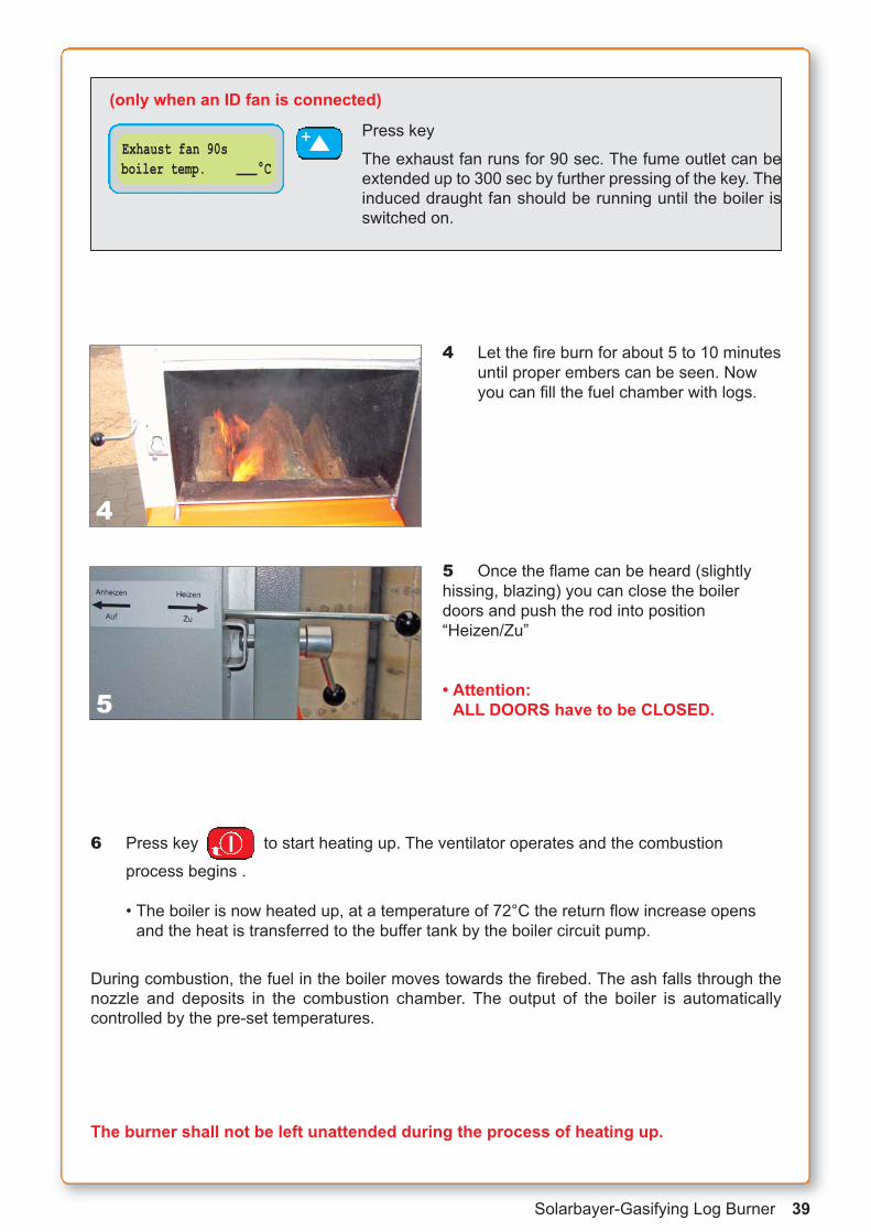
4 Let the fire burn for about 5 to 10 minutesuntil proper embers can be seen. Nowyou can fill the fuel chamber with logs.
5 Once the flame can be heard (slightlyhissing, blazing) you can close the boilerdoors and push the rod into position “Heizen/Zu”
• Attention: ALL DOORS have to be CLOSED.
Press key
The exhaust fan runs for 90 sec. The fume outlet can beextended up to 300 sec by further pressing of the key. Theinduced draught fan should be running until the boiler is switched on.
Exhaust fan 90sboiler temp. °C
!+(only when an ID fan is connected)
4
5
6 Press key to start heating up. The ventilator operates and the combustion process begins .
• The boiler is now heated up, at a temperature of 72°C the return flow increase opensand the heat is transferred to the buffer tank by the boiler circuit pump.
During combustion, the fuel in the boiler moves towards the firebed. The ash falls through thenozzle and deposits in the combustion chamber. The output of the boiler is automatically controlled by the pre-set temperatures.
The burner shall not be left unattended during the process of heating up.
I!

40 Solarbayer-Gasifying Log Burner
SOLARBAYER recommendation:
The electronic control unit is delivered with factory settings and pre-wired. It is only the boiler circuit pump of the return flow increase (e.g. the Laddomat 21) and the optional ID fan that haveto be wired at the designated strip terminal.
We recommend to leave the boiler temperature set at 90°; this achieves an optimal gasifying effect and the best efficiency. The exhaust gas tract remains cleaner and ash formation is ratherlow (for settings see chapter 6.3.1)
We recommend leaving the exhaust gas temperature at 80°C, to maintain the firebed over a longer period of time (for settings see chapter 6.3.2.)
The most common reason for malfunctions is air in the heating system constraining circulation.With easy piping, like displayed by the diagrams in the appendix, the air can exhaust on its own.
Please use our piping diagrams and our storage systems, as well as our Laddomat for best return flow increase. Well adjusted systems guarantee functional boiler technics.
These are only tips for heating, please keep in mind that you are heating with a natural product. The wood has to be stored air-seasoned for at least two years. Dry heating material isthe basic requirement for an almost smokeless combustion.

Solarbayer-Gasifying Log Burner 41
8.2 Refuelling the Boiler
It is also possible to refuel the boiler during the burning cycle. Care has to be taken when opening the fuel chamber door, to avoid smoke exit from the boiler. With chimneys below 8 meterwe recommend to install the optional available induced draught fan. But you can also refuel theboiler without an ID fan.
Attention: Make sure that the damper is open (in position “Anheizen/Auf”) to insure proper draft.
The timber logs have to be placed in the fuel chamber in such a way that the fuel chamber door can still be closed. A forcibly closing might damage the door lining.
We recommend that the boiler should only be operated by persons over 18 yearsof age.
Refuelling without induced draught fan
Boiler offboiler temp °C
The boiler is not operating and the fuel control light flashes. The boiler has to be refuelled if more heat is required.
boiler offboiler temp. °C
Press button => boiler switches off I!
Burn-up TURBOboiler temp. °C
Press button to start boiler againI!
Ventilation 15sboiler temp. °C
press once => fan runs for 15 sec.Each time the button is pressed again, another 15 sec isadded to the running time off the fan.
"-
To avoid smoke rising out off the burner, open door slightly and wait for a few seconds, beforefully opening the fuel chamber door.
Ensure doors are closed correctly after refuelling.
Before refuelling the boiler open the damper (set to Anheizen/Auf position)After closing the fuel chamber door close damper (set to Heizen/Zu position)

42 Solarbayer-Gasifying Log Burner
Refuelling the boiler with induced draught fan „optional“The SOLARBAYER Log Burner comes with a forced draught fan as standard. The electroniccontrol enables the additional connection of an induced draught fan.
The ID fan supports the optimal withdrawal of the fumes out of the fuel chamber when refuelling the boiler. Fumes do therefore not escape through the open door when refuelling.
The ID fan comes as optional equipment and is available in two sizes, 160 mm and 200 mm(depending on boiler size).
It is possible to refuel the boiler during the heating process.When the ID fan is operated the forced draught fan is switched off automatically.
Exhaust fan 90sboiler temp. °C
Press key.
Exhaust fan switches on for 90s. Each time the key ispressed, the time will extend by 90 seconds up to a maximum of 300 seconds.
Boiler offboiler temp. °C
Press key, burner is off I!
Burn-up TURBOboiler temp. °C
Press key
Boiler starts the heating up phaseI!
!+
Open the bottom door slightly and wait before open the door fully, to prevent the exit of smokeinto the room.
Close all doors fully and tight after the boiler has been refuelled.
8.3 Shutting off the boiler
Boiler offboiler temp. °C
Automatic shut off:The boiler is shut off when the exhaust gas temperature islower than the preset switch off temperature. The yellowLED diode is lighting, the display shows “boiler off”.
Boiler offboiler temp. °C
Manual shut off:Press key.
If heat requirement does no longer exist and the boilerhas to be refuelled no more the boiler can be shut off.
I!
NOTE: If the boiler is shut off manually and restarted the boiler program “Burn-up TURBO” is activated. If the boiler is not refuelled and the exhaust gas temperature is already below 120°Cthe boiler cannot be shut off automatically.
The boiler has to be shut off manually after the combustion.

Solarbayer-Gasifying Log Burner 43
8.4 Heat Value Chart / Storing of Firewoodmoisture content in % 10 % 15 % 20 % 25 % 30 %
Type / Density 1) Unit Heat Value in kWh
spruce kg 4,61 4,32 4,02 3,73 3,44
379 kg TM/fm fm 1942 1925 1906 1885 1860
rm 1360 1348 1334 1319 1302
Pine kg 4,61 4,32 4,02 3,73 3,44
431 kg TM/fm fm 2209 2189 2168 2144 2116
rm 1546 1533 1518 1500 1481
Birch kg 4,43 4,15 3,86 3,58 3,30
558 kg TM/fm fm 2748 2723 2695 2664 2627
rm 1923 1906 1887 1864 1839
Oak kg 4,43 4,15 3,86 3,58 3,30
571 kg TM/fm fm 2812 2786 2758 2726 2689
rm 1968 1951 1931 1908 1882
Poplar kg 4,43 4,15 3,86 3,58 3,30
353 kg TM/fm fm 1738 1723 1705 1685 1662
rm 1217 1206 1193 1179 1163
1) values in kg dry residue (TM) per solid cubic metre (fm)
timberin solid cubic metre (fm)
split timberin stere or stacked cubic metre (rm)
1,0
m
1,0 m1,0 m
1,0 m
1,0 m
1,0 m
1,0
m
1,4
m
0,7
m
1,0 m
1,0 m
1,0 m
1 fm
0,7 fm
1,4 rm
Storing of split timberFreshly cut timber contains bet-ween 45 to 60% water. With logwood boilers, however, you canonly use timber with a maximummoisture content of 20%. Therefore, it is necessary to dry(season) the timber before use.
We recommend the following foran optimal storing of split timber:
# store stack of woods protec-ted from rain
# split into logs before storing
# create dry ground for storing and keep of the ground to ensure air circulation (e.g. pile on long timbers, etc.)
# store in wind exposed placesif possible (e.g. at the edge of the forest not inside it)
# when stored closed to buil-dings ensure gap is left bet-ween buildings and logs,
# try to store logs south facing,
# put daily requirement of logs in heated rooms (e.g. boiler room to preheat the fuel!)
# when stored in buildings without special fire protectionequipment you have to regardthe maximum allowable amo-unt of fuel
1 solid cubic metre(fm) = 1,4 stacked cubic metre(rm)1 stacked cubic metre (rm) [Bavarian 1 stere]= 0,7 solid cubic metre (fm)
1,0 rm

44 Solarbayer-Gasifying Log Burner
9. Boiler Maintenance
9.1 Cleaning the boilerIf dry wood is used and the minimum temperature of the return water is kept at 72°C the conta-mination in the fuel chamber, the combustion space and the heat exchanger will be kept at a mi-nimum.
Cleaning of the fuel chamber (gasification chamber)The formation of tar in the fuel chamber (gasification chamber) is a usual effect. We recommendto burn the tar under controlled conditions with slightly opened upper boiler door and heating-up damper. Since the interior walls of the boiler are provided with an aluminium paint coat tarshould not be scraped off (applies to SOLARBAYER 25, 40).
You have to clean the primary air ducts if they are blocked.
An excessive quantity of ash in the fuel chamber which does not fall through the nozzle into thecombustion chamber has to be removed.
Ash and dust in the combustion chamber are removed with the scraper. If necessary, the ash inthe combustion chamber is to be removed once a week.
New fuel chamber The fuel chamber after a few days of service.The formation of tar is absolutely normal andis going to be burned off with the regular fuel.
Cleaning of the fuel chamber (the pictureshows the cleaning of the nozzle)
Primary Air Ducts
delivered along with theboiler:
ScraperPokerRound scraper

Solarbayer-Gasifying Log Burner 45
Cleaning the heat exchangerThe pipes of the heat exchanger need to be cleaned once a month. The cleaning period extends itself when the ideal (dry) fuel is used. For the cleaning of the heat exchanger it is necessary toremove the cover to provide access to the pipes of the heat exchanger.
NOTE: Make sure that the boiler room is adequately vented during the cleaning process (dustformation)
Remove the cover of the heat exchanger (don’t use any tools)
Loosen the cover of the heat exchanger (13mm flat spanner)
Clean heat exchanger with the round scraper.

46 Solarbayer-Gasifying Log Burner
Cleaning of primary and secondary air ductsAir permeability of the boiler is the fundamental requirement for proper combustion. If you usewood chips as fuel it is necessary to clean the air ducts at least once a season. The removal ofthe ventilator casing and its sheet metal plate gives space to the primary and secondary air ductswhich have to be cleaned with a vacuum cleaner. Afterwards, their air permeability has to bechecked.
Loosen the two screws of the ventilator casingand remove cover
Disconnect the cables
Disconnect power before disconnectingthe cables
Loosen screws of the sheet metal plate andremove ventilator together with the plate.When mounting them again make sure thatthe sealing is tight-fitting.
Suck debris from air ducts as shown
Warning!Before removing ventilator cover disconnect mains
supply!

Solarbayer-Gasifying Log Burner 47
9.2 How to Measure the Exhaust GasesPlease regard the following aspects for exhaust gas measurements:1. Clean boiler thoroughly about 3 days before measurement
2. The exhaust gas temperature has to be set on 250°C (only while measuring)
3. The buffer tank has to have enough heat capacity (cold buffer tank)
4. Use dry timber with about 10-20% moisture capacity, adjust timber length to length of fuel chamber, edge length about 10-15cm
5. Heat up the boiler approx. 2 hours prior to measurement
6. Pound embers
7. Place wood on the embers, completely fill the fuel chamber
8. Wait for approx. 10 min
9. start exhaust gas measuring
The measurement has to take place when the boiler is fully loaded.The ventilator capacity of the boiler should be in full service (100%)
30 60 90 120 150 180 210 240 2700
4800
4000
2000
6000
8000
CO-Wert
Zeitin min
Anheizen Abbrandphase Ausbrand
in ppm
1000500
1 Std. 2 Std. 3 Std. 4 Std.
zul. ppm-Wertmax.für die Abgasmessung
optimalerWert
ca. 40 min ca. 3 Std. ca. 1 Std.
The diagram shows that the carbon monoxide output is highest during the heating up process
Therefore, the exhaust gas measurement has to take place during combustion (in themiddle of the burn cycle)
CO-valuein ppm
Heating upapprox. 40 min
Combustionapprox. 3 hours
Burnoutapprox. 1 hour
Time inmin

48 Solarbayer-Gasifying Log Burner
70°
80°
90°
100°maximale Kesseltemperatur 95°(Notaus)
Pumpenzwangsanlauf bei 85°
Verlauf eingestellte
20°
30°
40°
50°
60°Verlauf eingestellte Kesseltemperatur 90°
Anheizen AusbrandBrennphase
9.3 Boiler and Exhaust Gas Temperatures during Operation
Boiler temperatures during heating process
Heating up Firing stage Burnout
maximum boilertemperature 95°C(emergency stop)
forced starting ofthe pump at 85°C
preset boiler tempe-rature 90°C
Exha
ust g
as te
mpe
ratu
re
Heating up Firing stage Burnout
Boiler off at an exhaust gastemperature of80°C
Pump and boiler on at 80°C e.g.
Heating up and firing stage
Exhaust gas temperature at 160°C +/- 10°C

Solarbayer-Gasifying Log Burner 49
10. Maintenance & Repair of the BoilerThe operator is responsible for regular checks and maintenance of the boiler. During operationof the boiler it is necessary to check the pressure, the seal of the boiler doors and tightness ofall boiler components and the proper operation of the ventilator.
Tightness of boiler doors:The boiler doors are fixed at three points: at two pintles and the closing catch. If the door doesnot fit tightly, it is possible to close the door and to adjust the hinge. By loosening and readjustingthe counter nut, the screw of the hinge can be turned and the door can be adjusted.
Tightness of damper:When cleaning the heat exchanger, check for a clean surface of the damper. A damper that doesnot close tightly may lead to reduction in the boiler output.
Operation of ventilator:The most important requirement for a reliable operation of the ventilator is a clean, dust free environment. This has to be particularly regarded.
Wearing Parts are:- the refractory nozzle
- the seal of the boiler doors
- seal of the heat exchanger casing
- combustion chamber (cf. chapter 5.7)
- all flame-swept parts
Service notes:Hinges and moving parts have to greased regularly.
Fan and air ducts have to be cleaned annually.
Pressure nipples for the thermal safety valve have to be checked annually.
Safety devices have to be checked regularly
Regular boiler cleaning, as often as necessary

50 Solarbayer-Gasifying Log Burner
11. Troubleshooting
Problem Possible reason Solution
Power drop. Boiler is highly contaminated
Nozzle is broken
The moisture content of thefuel used is too high, wrongtimber length
Clean the boiler
Check nozzle, exchange if necessary
Use dry timber, adjust timberlength
After closing the damper theboiler burns for a little whileand then only smokes
Secondary air adjustment isincorrect
The moisture content of thefuel used is too high, wrongtimber length
Check secondary air adjustment
Check if the fan flap (blowbackflap) of the forced draught fanopens
Adjust timber length
After closing the door smokeescapes through the doorsealing
Hinge adjusted incorrectly
Seal is broken
Adjust door (cf. chapter 5.3)
turn around or remove sealingcord of the door
The damper does not open The damper is covered withtar
The moisture content of thefuel used is too high, wrongtimber length
Adjust the boiler, exhaust gasand switch off temperature tothe Solarbayer settings.
Adjust timber length
Smoke comes into the boilerroom after opening the dam-per and the fuel chamber door
Low chimney draught The chimney has to match thetechnical requirements (cf.chapter 2.3)
Retrofit an ID fan
Cracks in lining No defect
Deformation of the steel tank No defect
Forced draught fan does notrotate
Starting capacitor is broken
STB has released
Replace capacitor
Unlock STB
Boiler switches off after heating up
Wrong temperature for boilerswitch off selected
See chapter 6.3.2
No display No tensionFuse brokenMotherboard defect
Check fuse and remove whennecessary
Replace motherboard
Solarbayer-Gasifying Log Burner 51
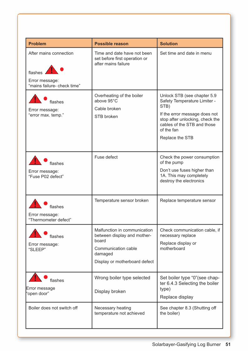
Problem Possible reason Solution
After mains connection
flashes
Error message: “mains failure- check time”
!
Time and date have not beenset before first operation orafter mains failure
Set time and date in menu
flashes
Error message:“error max. temp.”
! Overheating of the boilerabove 95°C
Cable broken
STB broken
Unlock STB (see chapter 5.9Safety Temperature Limiter -STB)
If the error message does notstop after unlocking, check thecables of the STB and thoseof the fan
Replace the STB
flashes
Error message:“Fuse P02 defect”
! Fuse defect Check the power consumptionof the pump
Don’t use fuses higher than1A. This may completely destroy the electronics
flashes
Error message:“Thermometer defect”
! Temperature sensor broken Replace temperature sensor
flashes
Error message:“SLEEP”
! Malfunction in communicationbetween display and mother-board
Communication cable damaged
Display or motherboard defect
Check communication cable, ifnecessary replace
Replace display or motherboard
flashes
Error message“open door”
! Wrong boiler type selected
Display broken
Set boiler type “0”(see chap-ter 6.4.3 Selecting the boilertype)
Replace display
Boiler does not switch off Necessary heating temperature not achieved
See chapter 8.3 (Shutting offthe boiler)

52 Solarbayer-Gasifying Log Burner
12 Wiring diagram
12.1 Typical wiring diagrams without oil/gas-fired boilerNote: These drawings are schematic diagrams by SOLARBAYER GmbH and do not replace a professional design
Log boiler – 2 Buffer tanks – Domestic hot water tank – Solar
Log boiler – Buffer tank – Domestic hot water tank
SolarbayerHolz-
vergaser
Schichtleit-speicher
Solarspeicher
AG
Solarspeicher
SolarbayerHolz-
vergaser
Schichtleit-speicher
Schichtleit-speicher

Solarbayer-Gasifying Log Burner 53
Log boiler – Buffer tank with solar coil – Domestic hot water tank – Solar
Log boiler – 2 Buffer tanks with solar coil – Domestic hot water – Solar
AG
SolarbayerHolz-
vergaser
Schichtleit-speicher
Solarspeicher
AG
SolarbayerHolz-
vergaser
Schichtleit-speicher
Solarspeicher
Schichtleit-speicher

54 Solarbayer-Gasifying Log Burner
12.2 Typical wiring diagrams with oil/gas-fired boilersBoiler circuit with oil/gas with boiler charge control
Note: These drawings are schematic diagrams by SOLARBAYER GmbH and do not replace a professional design
Log boiler – Oil/Gas boiler – 2 Buffer tanks – Domestic hot water tank – Solar
Log boiler – Oil/Gas boiler – Buffer tank – Domestic hot water tank
SolarbayerHolz-
vergaser
Trinkwasser-speicher
Öl-/Gas-kessel
Schichtleit-speicher
AG
SolarbayerHolz-
vergaser
Schichtleit-speicher
Schichtleit-speicher
Solarspeicher
Öl-/Gas-Kessel

Solarbayer-Gasifying Log Burner 55
Log boiler – Oil/Gas boiler – Buffer tank with solar coil – Domestic hot water tank – Solar
Log boiler – Oil/Gas boiler – 2 Buffer tanks with solar coil – Domestic hot water tank – Solar
AG
SolarbayerHolz-
vergaser
Schichtleit-speicher
Solarspeicher
Öl-/Gas-Kessel
AG
SolarbayerHolz-
vergaser
Schichtleit-speicher
Schichtleit-speicher
Solarspeicher
Öl-/Gas-Kessel

56 Solarbayer-Gasifying Log Burner
Always disconnect mains power supply before opening electrical covers to avoid electric shock.All wiring should be carried out by qualified personnel only!
Components to connect at installation by qualified electrician:Boiler circuit pump (Laddomat)Cable 3x 1,5$ID fan (optional)Cable 3x 1,5$
13. Technical Service (Qualified persons only)
13.1 Software adjustment For changes concerning the firmware please contact SOLARBAYER
13.2 Wiring Diagram (Qualified persons only)Electrical connection of exhaust gas thermometer
boiler sensor
exhaust gas sensor
ID fan (optional) STB ventilator
Pump max. 200 W room thermostat
power supply230V, 50Hz

Solarbayer-Gasifying Log Burner 57
Notes
58 Solarbayer-Gasifying Log Burner
Notes for customers and conditions of guarantee
- Claims regarding missing items upon delivery must be made to the supplier in accordance with the regulations of the Code of Commercial Law and the Civil Code.
- Claims with regard to damage and defects due to transport must be made to the carrier by the customer atdelivery of goods.
- Period of guarantee is 24 months from selling date.- Guarantee applies only if the boiler was put into operation by a qualified service engineer. Otherwise the
Guarantee Law of the EU applies. - Guarantee applies only if all electrical installations connected to the controller are connected by a qualified
service engineer and if there are specified in the records about the connection of the equipment. - Guarantee applies to construction, material used and realisation of the product. - The transport costs of the service engineer are not included in the scope of repair work during guarantee
period (transport costs shall be paid fully by the customer).
Guarantee does not include: - Wearing parts: seals for boiler doors, seals for cover of heat exchanger, seals for ventilator, refractory
nozzle, refractory lining and fireclay bricks- Defects caused by the customer himself- Defects caused due to not following assembly instructions, improper handling and maintenance or defects
caused by handling adverse to the purpose specified or if the product was used for a purpose other than specified; defects caused by bad or improper handling
- otherwise, the regulations of the Civil Code apply to the guarantee.
SOLARBAYER reserves the right of changes made to the product within the scope of product innovation.
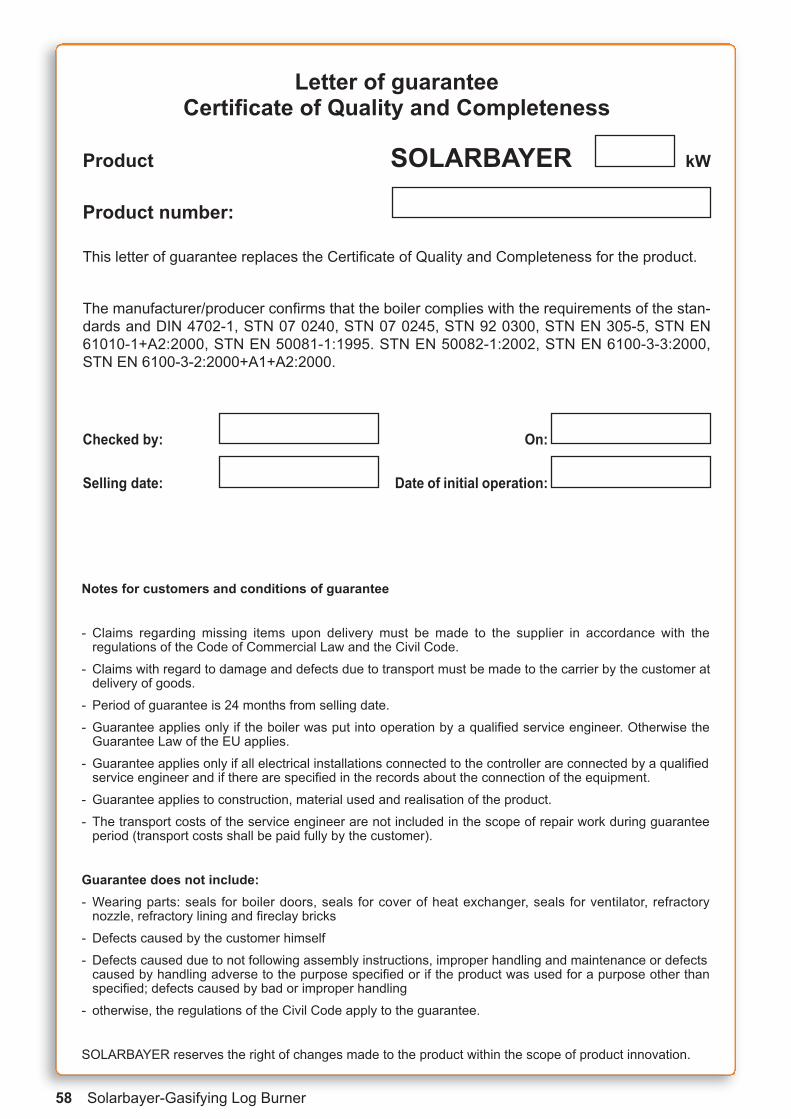
Letter of guaranteeCertificate of Quality and Completeness
Product SOLARBAYER kW
Product number:
This letter of guarantee replaces the Certificate of Quality and Completeness for the product.
The manufacturer/producer confirms that the boiler complies with the requirements of the stan-dards and DIN 4702-1, STN 07 0240, STN 07 0245, STN 92 0300, STN EN 305-5, STN EN61010-1+A2:2000, STN EN 50081-1:1995. STN EN 50082-1:2002, STN EN 6100-3-3:2000,STN EN 6100-3-2:2000+A1+A2:2000.
Checked by: On:
Selling date: Date of initial operation:

Solarbayer-Gasifying Log Burner 59
Declaration of conformityÜbereinstimmungserklärung des Herstellersnach Europäischer Maschinenrichtlinie 98/32
ausgestellt gemäß § 12 Abs. 3 Buchst. a) des GesetzesNr. 264/1999 der Gesetzessammlung und 97/23 EC // 98/32
SOLARBAYER® GmbHAm Dörrenhof 22
D-85131 Pollenfeld
declares on their own responsibility that the products specified hereafter correspond to the re-quirements of the technical regulations, that the products are safe under the conditions stipula-ted for their use, and that all steps were taken to ensure the compliance of the following productswith technical documentation and the requirements by the corresponding regulations by the Go-vernment.
Product: Thermal boilers SOLARBAYER 14.9 to 80
Type: Solarbayer 14.9, Solarbayer 25, Solarbayer 40, Solarbayer 50, Solarbayer 80
Importer: Solarbayer GmbH
The products listed are in accordance with the following standards:
Thermal boilers for solid fuel in accordance with EN 303-5 and DIN 4702-1,
STN 07 0240, STN 07 0245, STN 07 7401, STN 73 4210, STN 06 1610, STN 03 8240, STN 690010, STN 44 352, STN 06 1008, STN EN 303-5, STN EN 287-1, STN EN 287-2, STN EN50081-1:1995, STN EN 50082-1:2002, STN EN 61000-3-2:2000+A1:2001+A2:2001, STN EN61000-3-3:2000.
Additional data: Certificates
No. A10.1/01/0362/1/C/C03 dated 11.12.2001
No. A10.1/01/0363/1/C/C03 dated 11.12.2001
No. 4502 A/03/0095/1/C/C03 dated 31.3.2003
TGM VA HL 7043 dated 26.2.2004 for Austria, Germany, Switzerland
TGM VA HL 7042 dated 27.2.2004 for Austria, Germany, Switzerland
Declaration of conformity by manufacturer (Ü-mark)
in accordance with European Machine guideline DIN 4702-1, -EN 303-5, EMR 98/37
EMV guideline 89/336 Low voltage Guideline 72/23
Place of issue: Pollenfeld Name: Kraus Martin
Date of issue: 01.11.2005 Title: Managing Director
Signature:
Kraus
TÜV-Prüfungaccording to DIN EN 303-5

60 Solarbayer-Gasifying Log Burner
Phone: +49 (0) 84 21 / 90 39 27Fax: +49 (0) 84 21 / 90 39 28E-Mail: [email protected]
www.solarbayer.de
This manual and the pictures and drawings withinare protected by the copyright of SOLARBAYER GmbH
Technical changes and errors are reserved
(2708)
Am Dörrenhof 2285131 Pollenfeld / Preith
SOLARBAYER® GmbH
We design for your future