vertical medium-size gas boiler boiler boiler……………..krb.co.kr/english/products/medimum...
TRANSCRIPT

Model
* KS , KR - 50N (58.1 kW)
* KS , KR - 70N (81.4 kW)
* KS , KR - 100N (116.3 kW)
* KS , KR - 150N (174.4 kW)
* KS , KR - 200N (232.6 kW)
Technical information and Installation Servicing Instructions
V
ertic
al M
ediu
m-S
ize
Gas
boi
ler.
......
....
Boi
ler.
......
......
. boi
ler…
……
……
..
1페이지

CONTENTS
1) overall view 1 -1. Genearal informaion ************************************** 3 2) Product description 2 - 1. Boiler Specification ************************************** 4 2 - 2. Product dimensions ************************************** 5 2 - 3. Burner Specification ************************************** 6 3) Installation 3 - 1. Standard chmnet installation ************************************** 7 3 - 2. Standard heating & hot water installation ************************************** 9 3 - 3. Standard gas connection installation ************************************** 11 3 - 4. Gas Bunner connection spec ************************************** 12 3 - 5. connecting Electricity ************************************** 13
4) Main part specification 4 - 1. Gas valve ************************************** 14 4 - 2. Ignition transformer ************************************** 16 4 - 3. Ignition bar ************************************** 17 4 - 4. Adjustment and gas conversion ************************************** 18
5) Burner direection for assembly 5 - 1. Burner part exploded view ************************************** 19
6) Teat working 6 - 1. Check list before switching - on ************************************** 20 6 - 2. First ignition operation ************************************** 21
7) Diretion for assembly 7 - 1. Boiler part exploded view ************************************** 22 7 - 2. Part name ************************************** 23 8) Maintenance guide 8 - 1. Assembly of Burner ************************************** 24 8 - 2. Assembly of Temp. and Overheating Sensors************************************** 25 8 - 3. How to clean Heat exchager's Exhaust tube ************************************** 26 9) Function of the controller 9 - 1. Main controller part mane ************************************** 27 9 - 2. Room control part mane (CTR-5700 plus) ************************************** 29 9 - 3. Room control LED panel ************************************** 30 10) Troubleshooting guide (error code) 10 - 1. Finding failure ************************************** 31 11) Technical Data Table ************************************** 32 10) Memo ************************************** 33 11) Warranty ************************************** 34
2페이지

1. overall view
These instructions are suitable for KS, KR Series Vertical Medium-Size Gas boiler;
Do not forget this instruction.
To ensure the correct installation, commissioning and servicing of domestic central heating system.
1. Features of Vertical Medium-Size Gas BoilerAtmospheric pressure inside the furnace is maintained higher than the outside pressure. This Pressure difference
causes the emission of exhaust gas naturally. KITURAMI Boiler has no structure problem such as low temperature
corrosion, flue blockage, scale accumulation inside the exhaust tube, so it has long-life and reduces fuel costs
considerably.
2. Electronic Automatic Control Device (Korea Patent No.17570)Electronic Automatic Control Device(CTC) judges the operation status of boiler and controls it. CTC is the high-tech controller with
the program for self-diagnosis function, automatic control function, Hot water-only mode, Sleep mode and Out of house mode.
3. Steel frame for carrying handleSteel frame is equipped as the carrying handle to prevent from case damage on transportation and to install and transfer easily.
4. Turbo Cyclone Burner (Korea Patent No.101040)Kiturami Turbo Cyclone Burner burns combusted air secondarily with a special metal plate heated up to 800 like a turbo engine
of an automobile. It's different from general burner which burns injected fuel from nozzle in the air. It's eco-friendly and acquires
NT(Net Technology). Turbo Cyclone Burner guarantees environment-friendliness, safety and long-life.
1 - 1 General Information
3페이지
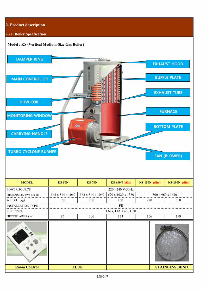
2. Product description
Model : KS (Vertical Medium-Size Gas Boiler)
POWER SOURCE
DIMENSION (Wx Dx H)
INSTALLATION TYPE
FUEL TYPE
FLUERoom Control
220 - 240 V/50Hz 800 x 960 x 1620
KS-50N KS-70N KS-100N (slim)
562 x 814 x 1060 620 x 1020 x 1380
KS-150N (slim)
STAINLESS BEND
350FE
LNG, 13A, G20, G3085
150150 220
133
160
2 - 1 Boiler Speafication
562 x 814 x 1060
HETING AREA ()
WEIGHT (kg)
106 166 199
KS-200N (slim)MODEL
EXHAUST HOOD
BUFFLE PLATE
EXHAUST TUBE
FURNACE
BOTTOM PLATE
TURBO CYCLONE BURNER
CARRYING HANDLE
MAIN CONTROLLER
MONITORING WINDOW
DHW COIL
DAMPER RING
FAN (BLOWER)
4페이지
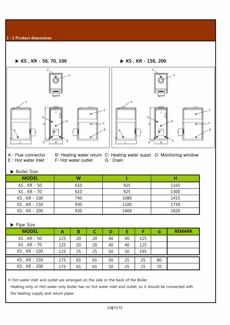
KS , KR - 50, 70, 100 KS , KR - 150, 200
A : Flue connector B: Heating water return C: Heating water supply D: Monitoring window E : Hot water inlet F: Hot water outlet G : Drain
Boiler Size
Pipe Size
A B C D E F G
125 20 20 40 40 125
125 20 20 40 40 125
125 25 25 50 50 195
175 65 65 50 25 25 80
175 65 65 50 25 25 70
※ Hot water inlet and outlet are arranged on the side or the back of the Boiler
Heating-only or Hot water-only boiler has no hot water inlet and outlet, so it should be connected with
the heating supply and return pipes
KS , KR - 70
KS , KR - 100
KS , KR - 150
KS , KR - 200
MODEL
KS , KR - 50
REMARK
KS , KR - 200 930 1400 1820
KS , KR - 100 740 1080 1415
KS , KR - 150 930 1100 1750
L H
KS , KR - 70 610 925 1300
KS , KR - 50 610 925 1165
2 - 2 Product dimensions
MODEL W
5페이지

* BURNER MODEL : TGB - 50 (54kW - 74 kW) TGB - 70 (66kW - 103 kW) TGB - 100 (93kW - 203 kW)
TGB - 200 (179kW - 262 kW)
※ Features of Turbo Cyclone Burner
800 like a turbo engine of an automobile, considerably reducing fuel costs and exhausts.
2 - 3 Burner Specification
Kiturami Turbo Cyclone Burner burns combusted air secondarily with a special metal plate heated up to
TGB - 150 (93kW - 174 kW)
BURNER TUBE
AIR DAMPER
BURNER BODY
GAS VALVE PLUG
LOW PRESSURESWITCH
GAS VALVE
IGNITIONTRANSFORMER
6페이지

3. Installation
Installing flue in case of no existing flue 1. As shown in Figure 1-1, install stainless flue outside and then install
air intake vent and exhaust gas vent for boiler room.
2. Cover the Flue and the surface of the wall with the nonflammable
material to prevent fire or damage by high temperature of exhaust gas.
3. Install the flue part connected with exhaust hood should be installed
longer than 50cm, which prevents condensate from flowing into the
inside of boiler.
4. Install the condensate drain at "A" region to prevent the condensate,
generated in the outer flue, from flowing into the inside of boiler.
Installing flue in case of existing flue
1. Check the air leakage at the joint between outer flue and inner flue,
and seal the joint with the nonflammable material.
2. Install air intake vent at the bottom and exhaust gas vent at the top.
3. Keep the distance more than 200mm between the outer flue and the inner
flue's end, which smoothes the emission of exhaust gas.
4. Install the condensate drain to discharge the condensate, generated
in the outer flue.
3-1 Standard chimney installation
BURNERDRAIN
cleaning
7페이지

Installing the Boiler
1. Do not install the boiler in tighty shut area without ventilation or in bathroom
with a lot of moisture. It may cause the critical lack of oxygen or imperfect
combustion.
2. Install the boiler horizontally and solidly on the nonflammables such as
concrete or bricks which can withstand the weight.
3. Do not install the boiler in open veranda or outdoor for the frost protection.
4. Place the boiler in the area with enough space to check and repair it.
5. Use a plug acceptable only for the boiler.
6. Install the boiler 50mm higher than the floor.
Caution on installing Flue
1. The highest part of flue should be out of wind pressure belt and
not be influenced by rain and wind.
2. When there is a high building or an obstacle within 1M around the flue, the flue should be Min. 1M higher than the high building.
3. If the flue is placed in a wind pressure belt, the efficiency of the boiler
is getting lower because the imperfect combustion causes soot, and
that leads to safety shut down function, which means the boiler does not work well.
8페이지

※ In the above Figure, DHW inlet and DHW outlet are installed only on the Heating and Hot water boiler.
Be sure to install the hot water strainer to improve the durability of the boiler and the circulation pump.
Install the safety valve in case of difficulty to install the drain pipe at the Gas boiler, capacity of which is
more than 20,000kcal/h(232.5kW).
Caution on installing the pipe
1. Be sure to install a Air vent or Auto Air vent at the top of the pipes. 2. This product is for the working pressure 3.5kgf/ of cold water supply. Therefore, Install the pipe in accordance with 3.5kgf/ 3. Don't install any valve such as a pressure reducing valve and a check valve at the water supplement and the drain pipe. ※ Caution against the damage to the boiler due to user's negligence
4. Please install an open type expansion tank or the nitrogen tank(closed type) and a safety valve, appropriate to the capacity of the boiler to prevent the damage by the thermal expansion pressure. 5. If the boiler is directly connected to the water supply pipe, it may be damaged due to the high pressure of water supply. Therefore, be sure to install a pressure reducing valve and a check valve. ※ Keep the pressure of the cold water supply within 0.6 - 1.kgf/ to use the hot water sufficiently.
3 - 2 Standard heating & hot water installation
Safety
valve
DHW
Outlet
DHW lnlet
Drain valveBURNER CH Return
Circulation pump
CH Supply
streiner
* Heating coil
* radiator
* FCU
expansion
tank
Water tank
Over frow
Bath & kitchen
9페이지

3-2-1 Installing Downward piping type
3-2-2 Installing Upward piping type
expansion tank
Heating coil
Radiator
expansion pipe
Heating supply
pipe
circulation pump
Heating return
pipe
DHW outlet
Heating coil
Heating coil
Header
Water tank
Drain
자연순환방지배관
10페이지

1. For the piping materials, please use metallic pipe or flexible pipe, and surely insert O-ring for the seal and tighten nuts.
2. Install the gas middle valve in a spot that is easy to reach.
3. After connection, perform a gas leakage test to make sure there's no leakage.
4. Don't install the gas piping personally, have a qualified pipelayer fix it.
1. Any foreign material inside the pipe may reduce the heating efficiency or prevent the boiler from normal operation. Therefore, please equip a gas filter near the boiler when connecting the gas pipe as shown in Figure.
1. Only LPG gas tanks can be connected with each other in parallel for the boiler. Don't connect with other kitchen appliances such as a gas cooker as shown in Figure.
3 - 3 Standard gas pipe installation
Gas filterValve
leakage check
Gas hose
11페이지

3 - 4 Gas Burner connection spec ① When gas supply pressure is more than 300mmAq
AB
CD
E
② When gas supply pressure is less than 300mmAq
AB
C
At first, Gas Burner is set, based on 200mmH2O of the gas supply pressure.
-> In case of more than 300mmH2O, Adjust the basic pressure by the Manometer and Flow Regulator.
1. Gas connection 1). Make sure, using the labels on the packaging and the data plate on the appliance itself, that the boiler is in the correct
country and that the gas category for which the boiler was designed corresponds to one of the categories available in the
country where it will be used.
2). The gas supply piping must be created and measured out in compliance with specific legal requirements and in accordance
with the maximum power of the boiler; you should also make sure that the shut-off valve is the right size and that it is
connected correctly.
3). Check that the supplied gas corresponds to the type of gas for which the boiler was designed
(see the data plate located on the appliance itself).
It is also important to check that the pressure of the gas (methane or LPG) you will be using to feed the boiler is suitable,
because if it is insufficient the power may be reduced, causing inconvenience for the user.
2. Water connection 1). The illustration shows the connections for the water and gas attachments of the boiler. See valves configuration
2). Check that the maximum water mains pressure does not exceed 3bar; if it does, a pressure reducing valve must be
installed.
3). For measuring of the pipes and of the heating bodies in the heating system, the residual head value should be calculated
as a function of the requested flow rate, in accordance with the valves shown in the circulation pump graph
3. Drain connection 1). Extend the hose from the safety valve and connect the drain hole.
※ Caution ; Do not store any wettable things under the boiler or near the drain hole.
MAIN SAFETY GAS VALVE
Gas Manometer
Manual Gas Open Valve
Governer(Gas Valve)
(a component of the Burner)
GAS PIPE LINE (3/4" . 1")
(a component of the Burner)
GAS PIPE LINE (3/4" . 1")
Manual Gas Open Valve
MAIN SAFETY GAS VALVE
12페이지

3-5-1 Connecting Wires
※ This appliance is designed on AC 220V ~ 230V/ 50Hz.
This work of connecting wires is required by a qualified electrician.
1. Make sure that the earth connection is required for safety uses from any electric leakage or short-circuit.
2. Make sure that the connecting electricity - for example, connecting power and cable, wiring, earthing, etc - should
comply with the regulation.
3. If this appliance is not earthed by power plug, ensure to earth separately, by minimum 30cm inserted in the
ground. Note not to connect gas pipe, telephone wire and lightning conductor(rod) in order to avoid any
accident from lightning, surge, or the gas accident.
4. Make sure that the socket outlet is apart by over 30 cm from the appliance.
5. The power outlet has to have at least the minimum clearance of 30mm from the gas boiler
6. The grounding point need to be buried at least 30cm
3 - 5 Connecting Electricity
13페이지

4. MAIN PART SPEC
4 - 1 GAS VALVE ① Composition of Multiblock
Gas Filter
Pressure Switch
Shut Off Valve 1
Pressure Regulator
Shut Off Valve 2
Flow Regulator
② Gas Valve Structure
Pressure regulator
Flow regulator
Pressure measurement point
Shut Off Switch at low pressure
Filter
Flange
③ How to adjust the Gas valve
Pressure Adjustment (40 - 200mmHO)
Turn the pressure adjustment screw above the
Shutt Off Valve with the phillips screwdriver.
Adjust the pressure by turning clockwise or
counterclockwise.
* Clockwise : increasing the pressure
* Counterclockwise : decreasing the pressure
Gas Flow Adjustment
(able to control gas flow up to 30% of Max. flow)
Loosen the holding screw of Hydraulic breaker half a turn.
Adjust the Gas Flow by turning Hydraulic breaker clockwise.
* Clockwise : decreasing the flow
* Counterclockwise : increasing the flow
Opening speed Adjustment (Max 20sec - Min, < 1sec)
Pull off the cap of Hydraulic breaker and adjust the Opening
speed with the adjustment tool, as shown in Figure.
Clockwise : decreasing the speed
Counterclockwise : increasing the speed
4
56
1
2
3
V1
1
V2
2
10
18
14페이지

③ Gas filter Features : Gas filter is easy to clean and equipped inside the gas valve.
Specification
NO
1
2
④ How to clean and replace the Gas filter
Check the filter once a year.
Close main valve of gas supply pipe.
Open the filter cover and pick it off as shown in right figure.
Clean the filter with clean water or air.
※ In case of water clean, drain the filter dry completely.
After cleaning, in reverse order, assemble it.
In case that the filter is broken or it's ability has declined,
replace the filter.
MESH SIZE 50 Pipe Connector 3/4" / 1"
Working pressure
(Max.)0.5k gf/
Working Temp.
(Max.)
ITEM VALUE ITEM VALUE REMARK
80
15페이지
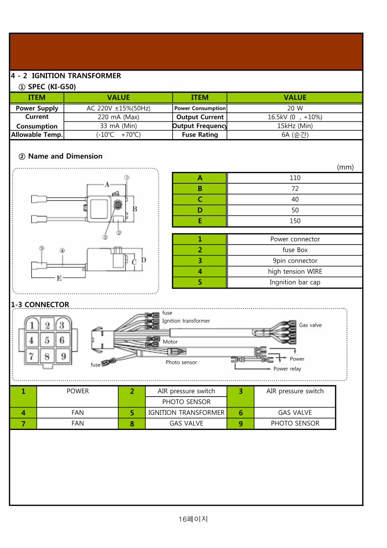
4 - 2 IGNITION TRANSFORMER
① SPEC (KI-G50)
② Name and Dimension
(mm)
1-3 CONNECTOR
1 2 3
4 5 6
7 8 9
2
3
45
FAN
Power connector
fuse Box
9pin connector
E
110
72
40
Power Supply
A
B
Output Current33 mA (Min)
(-10 +70)
Power Consumption
CurrentConsumption
Allowable Temp.
1
150
POWER AIR pressure switch
PHOTO SENSOR
AIR pressure switch
GAS VALVE
C
D 50
Output FrequencyFuse Rating
20 W16.5kV (0 , +10%)
15kHz (Min)6A (순간)
ITEM ITEM VALUEVALUEAC 220V ±15%(50Hz)
220 mA (Max)
high tension WIRE
Ingnition bar cap
IGNITION TRANSFORMER
GAS VALVE
FAN
PHOTO SENSOR
Gas valve
Power
Motor
fuse
Ignition transformer
fuse Power relay
Photo sensor
16페이지

4 - 3 IGNITION BAR
Specification
Name and Dimension1 A
2 B
3 C
4 D
How to adjust the location of ignition rod
1. Keep the gap between two Electrode rods by 3-4mm on
repairing the burner, changing the nozzle and disassembling it.
2. Fix the Ignition rod to the Burner solidly.
※ If the gap isn't kept or Ignition rod isn't fixed, Ignition failure may
occur.
How to adjust the Air damper
1. After loosening screw A, adjust B by hand.
2. After adjusting B to the desired number , fasten the screw A.
3. The number D is bigger, the air flow is more.
※ After checking the combustion status, adjust the air damper
appropriately. In case of excessive or deficient air flow, imperfect
combustion may occur.
TIME CHART
Normal combustion Abnormal combustion
※ Pre-purge time of TGB-200 is 32sec. And the other specification is same with the other Models.
ITEMWithstanding voltage
Insulation Resistance
26
3.5
VALUE97 M190
5.3
connection hole of Ignition rod
Electrode rod
VALUE ITEM18 KV/mm
10 14 - 10 15 Ωcm
connection nipple of Ignition transformer 152
14Epoxy
196 sccARC Resistance
HardnessThermal Resistance
Dielectric Constant
MOTOR
TEM/
SENSING
AIR SENSING
I/T
FR/SENSING
GAS VALVE
ALARM
MOTOR
TEM/
SENSING
AIR SENSING
I/T
FR/SENSING
GAS VALVE
ALARM
D
secsec
17페이지

The following adjustment and conversion operations must be carried out by qualified personnel. KITURAMI
Limited accepts no liability for damage to property or personal injury resulting from tampering with the boiler
by unauthorized persons.
1. Gas Pressure by Capacity
UNIT
kW
kcal/h
N/h
2. Nozzle Specification by Capacity
TGB - 50 , 70 TGB - 100 , 150 , 200
200 200 200 200 200
55
Fuel Consumption
70 95
50,000 70,000CAPACITY
1st Supply PressuremmH2O
2nd Supply Pressure
3.8 - 5.5 5.3 - 7.7 8.0 - 10.9 11.4 - 16.4 16.0 - 23.3
4 - 4 Adjustment and gas Conversion
MODEL TGB-50
174.4 232.6
TGB-150 TGB-200TGB-100TGB-70
58.1 81.4 116.3
85
100,000 150,000 200,000
18페이지

5. Assembly Instruction for Burner
NO NO NO
1 2 3
4 5 6
7 8 9
10 11 12
13 14 15
16 17 18
19 20 21
22 23 24
AIR PRESSURE SWITCH
5 - 1 Burner Part exploded view
CONNECTOR
BURNER COVER
NAMENAMENAME
DAMPER
GAS PECKING
BURNER MOTOR
MOTOR BASE (RIGHT)
GAS SUPPLY PIPE
NOZZLE
IGNITION TRANSFORMER
FAN
GAS VALVE
POWER RELAYPHOTO SENSORGAS VALVE NIPPLE
MOTOR BASE (LEFT)
NOZZLE HOLDER
GAS INJECTION PIPE
TUBE ASS'Y
STEBILRAIGE
MORTOR (FRONT)
IGNITION BAR
DIVISION PANEL
BURNER GASKET
19페이지

6. TEST WORKING
1). Before switching-on, please check the followings after finishing the installation of boiler, flue, pipes, and electricity.
① Is the boiler connected to the boiler-dedicated electrical outlet?
② Are there some combustible materials around the flue?
③ Has the boiler been installed in boiler-dedicated and well ventilated room?
④ Is there enough space for boiler inspection?
⑤ Has the Gas Leakage been inspected?
⑥ Does the boiler have good drainage on operating?
⑦ Has the boiler been installed horizontally on the nonflammable floor such as concrete floor or bricks?
⑧ Has the boiler's flue been kept warm completely? ⑨ Has the thermostat been connected to lines accurately? ⑩ Is the supplied gas identical with the Gas marked on boiler?
6 - 1 Check list before switching-on
1 2 3 4 5
7 8 9 106
20페이지

Date : …….……………………………… Installer : ……………………………………
6 - 2 FIRST IGNITION OPERATION
15. Check the ionisation current
Compleat………………………….
12. Check the working in DHW mode
Compleat………………………….
9. Set the heating power. See section Compleat………………………….
6. Fill the installation. See section Compleat………………………….
3. Check the gas tightness
Compleat………………………….
2. Check the type of gasandchange the gas ifnecessary
5. Check the exhaust fume. See section……
Compleat………………………….
8. Spin the pump.
Compleat………………………….
11. Balance the central heating circuit
Compleat ……………….………
14. Make a combustionrate with once pressing on RESET button during 5sec
1. Check the electricalsupply.
Compleat……………………
4. Measure the gas inlet
Compleat………………………….
7. Check the hydraulic tightness
Compleat………………………….
10. Adapt the requlationat the heating instation
Compleat………………………….
13. Adjust DHW flow rateon the boiler(if necessary)
Compleat………………………….
16. Explain to the enduaer the working of theboiler
Compleat……………………
21페이지
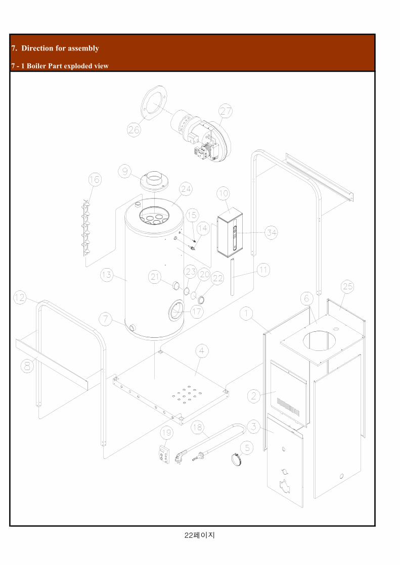
7. Direction for assembly
7 - 1 Boiler Part exploded view
22페이지

50K 70K 100K 150K 200K
1 Side panel
2 Front panel (UP)
3 Front panel (DOWN)
4 Bottom panel
5 Stainless bend (chimney)
6 Top panel
7 Stainless bend (exchanger)
8 reinforcement panel
9 Damper ring
10 Control box
11 Wire cover
12 reinforcement pipe
13 Heat exchanger
14 Temperature sensor
15 Low water sensor
16 Buffle plate
17 cestabul
18 Power code
19 Room controller
20 Mica
21 Peep hole pipe
22 Peep hole cap
23 Gas pipe packing (peep hole)
24 Exhaust hood
25 Back panel
26 Gas pipe packing (burner)
27 Burner ASS'Y
케스타블
스텐밴드(열교환기)
보강판넬
케이싱 (좌우)
버플플레이트
담바링
콘트롤박스
전선카바
Part Name (English)
스텐밴드(연통)
상부판넬
전면케이싱 (상)
전면케이신 (하)
바닥판넬
Model
온도센서
저수위센서
No
7 - 2 Part name
파워코드
케이싱 (뒤)
패킹 (버너)
버너
감시창 파이프
감시창 캡
주열교환기
ERP Code
가스켓 (감시창
배기후드
Korean
보강 파이프
실내온도조절기
감시창
23페이지

8. MAINTENCE GUIDE
8 - 1. Assembly Instructions for Burner
1. Plug off the power cord.
2. Close the Gas valve connected with main gas piping.
3. Disassemble screws fixed on front case and open the
case.
1. Separate the connector plug from burner.
2. Remove two nuts on burner flange by spanner.
3. Separate the burner by pulling forward.
1. Replace the gasket fixed on flange with new one.
2. Check the status of Burner (interval and fixed state of
ignition rod) and assemble the burner on flange.
3. Fix the burner by tightening nuts.
4. Assemble the connector plug on the exact location.
Tool
1
24페이지

8 - 2. Assembly Instructions for the Temperature Sensor and Low Water Sensor
1. Plug off the power cord.
2. Close the Gas valve connected with main gas piping.
3. Close the valves connected with the pipes.
4. Loosen screws fixed on front case and open the case.
5. Separate the control box and connector plug fixed
on the front of Heat exchanger.
1. Separate Temperature Sensor or Low Water Sensor by
turning it counterclockwise with spanner.
※ Check the scale on the Sensors.
1. After sealing the Sensor by Teflon, Assemble the Sensor
at the exact location by turning clockwise.
2. Connect the Sensor with connector plug.
※ After opening pipe valve, check the water leakage.
3. Assemble the connector plug and control box.
Tool
2
25페이지

8 - 3. How to clean Heat exchager's Exhaust tube
1. Plug off the power cord.
2. Close the Gas valve connected with main gas piping.
3. Loosen screws fixed on front case and open the case.
4. Loosen screws fixed on the top of Heat exchanger and
separate the panel.
5. Untie stainless band on the flue and separate the flue.
6. Loosen nuts fixed on Damper ring and separate
Damper ring from Exhaust hood.
7. Check the soot status of top of the Heat exchanger and
take Buffle plates out of Exhaust tubes.
8. Clean the soot inside the Exhaust tubes by using brush
or chemical.
9. In reverse order, assemble Heat exchanger.
Tool
3
26페이지

9. Functions of the controller
Model : GTX-5050N (13K/ 16K/ 20K/25K/30K)
1. Power supply / Alarm Lamp
- Lights when the boiler's power turned on and
flickers when the boiler in abnormal condition.
2. Power switch
- Boiler power On/Off switch
※ Gas sensing and Protection from cold winter function
work, even if the power is off.
9 - 1 Main Controller part name
10P connertor
Gas sensing
18P connertor
27페이지

1. Circulation PUMP : Lights when Circulation Pump operates.
2. Power lamp : Lights when Power is ON.
(Flickers when detecting abnormal signal between Room controler and Main controler.
3. Power switch : Switch for boiler power On/Off or Restart
4. Temperature : Display current water temperature in boiler.
5. Burner lamp : Lights when burner operates.
(Flickers when the water in Heat exchanger is not enough.)
GTX - 1550 (50K, 70K, 100K, 200K) GTX - 2201L (200K)
1. circulationpump
2. Power lamp
3. Power switch
5. Burner lamp
4. TEMPERATURE
1. circulationpump
2. Power lamp
3. Power switch
4. TEMPERATURE
5. Buener lamp
28페이지

9 - 2 Room Control panel (CTR-5700 plus)
4
5
6
7
8
9
LEGEND
1. LED panel 2. BOILER HEATING OPERATING CONDITION SELECT BUTTON (RPPM TEMPERATURE HEATING, TIMER HEATING, OUT GOING) 3. DOMESTIC HOT WATER, ONLY 4. GREEN INDICATOR - POWER SUPPLY 5. ADJUSTMENT NUMERIC INCREASING BUTTON EACH EUNCTION 6. ADJUSTMENT NUMERIC DECREASING BUTTON WITH EACH FUNCTION 7. CH TEMPERAYURE ADJUSTMENT BUTTON. 8. TIMER ADJUSTEMENT BUTTON 9. ON/OFF BUTTON
29페이지

9 - 3 Rooom control LED panel
LEGEND
1. When the boiler operates with room temperature heating mode, this symbol display 2. When the boiler operates with room temperature heating mode, this symbol display. 3. Current’s room temperature display in accordance with each heating modes 4. When the boiler operates with timer mode, this symbol display. 5. When the boiler operates with heating temperature mode, adjusted heating temperature display. More the BAR’s numbers, the heating temperature is higher 6. When the boiler is operating in each setting mode, this symbol display 7. When set the room temperature will changing, this symbol display. 8. When the room temperature will be changing, this symbol display 9. When the boiler doesn’t operate with timer mode, this symbol display 10. When the boiler operates with timer heating mode, this symbol display 11. When the boiler operates with outgoing mode, this symbol display. 12. When the boiler operates with DHW mode, this symbol display
30페이지
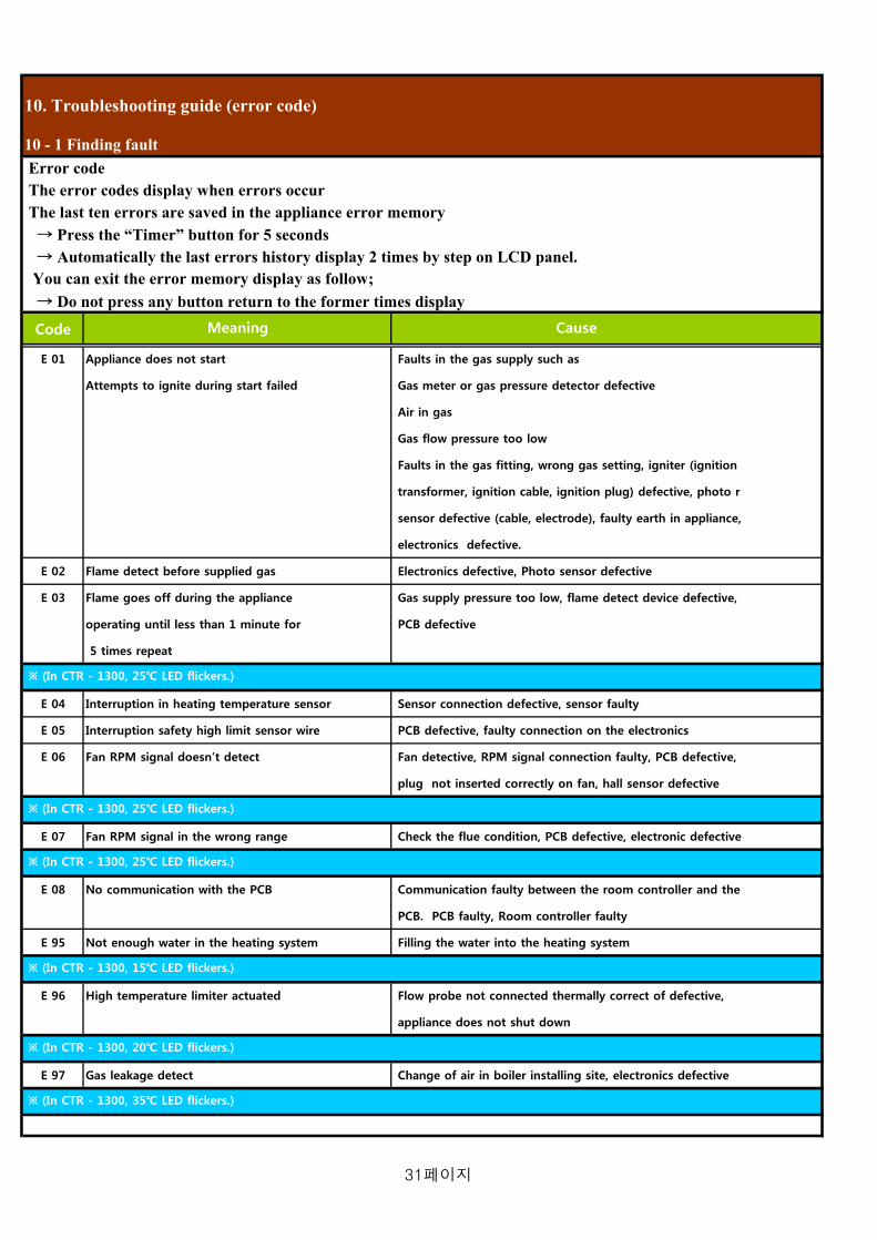
10. Troubleshooting guide (error code)
Error code The error codes display when errors occur The last ten errors are saved in the appliance error memory → Press the “Timer” button for 5 seconds → Automatically the last errors history display 2 times by step on LCD panel. You can exit the error memory display as follow; → Do not press any button return to the former times display
Code
E 01 Appliance does not start Faults in the gas supply such as
Attempts to ignite during start failed Gas meter or gas pressure detector defective
Air in gas
Gas flow pressure too low
Faults in the gas fitting, wrong gas setting, igniter (ignition
transformer, ignition cable, ignition plug) defective, photo r
sensor defective (cable, electrode), faulty earth in appliance,
electronics defective.
E 02 Flame detect before supplied gas Electronics defective, Photo sensor defective
E 03 Flame goes off during the appliance Gas supply pressure too low, flame detect device defective,
operating until less than 1 minute for PCB defective
5 times repeat
E 04 Interruption in heating temperature sensor Sensor connection defective, sensor faulty
E 05 Interruption safety high limit sensor wire PCB defective, faulty connection on the electronics
E 06 Fan RPM signal doesn’t detect Fan detective, RPM signal connection faulty, PCB defective,
plug not inserted correctly on fan, hall sensor defective
E 07 Fan RPM signal in the wrong range Check the flue condition, PCB defective, electronic defective
E 08 No communication with the PCB Communication faulty between the room controller and the
PCB. PCB faulty, Room controller faulty
E 95 Not enough water in the heating system Filling the water into the heating system
E 96 High temperature limiter actuated Flow probe not connected thermally correct of defective,
appliance does not shut down
E 97 Gas leakage detect Change of air in boiler installing site, electronics defective
Meaning Cause
10 - 1 Finding fault
※ (In CTR - 1300, 25 LED flickers.)
※ (In CTR - 1300, 35 LED flickers.)
※ (In CTR - 1300, 25 LED flickers.)
※ (In CTR - 1300, 25 LED flickers.)
※ (In CTR - 1300, 15 LED flickers.)
※ (In CTR - 1300, 20 LED flickers.)
31페이지

11. Technical Data Table
* specification are subject to change without prior notice to improve design and performance
kW(kcal/h)
N/h
Heating area (Max)
MINkW
(kca/h)
MAXkW
(kca/h)
%
rpm
W
/V
V1-V2
I1-I2
ON mmH2O
OFF mmH2O
ON mmH2O
OFF mmH2O
W
kiturami
star
bar(psi)
()
()
kW(kcal/h)
bar (psi)
ℓ/min (gpm)
bar (psi)
t=25 ℓ/min
t=30 ℓ/min
t=40 ℓ/min
V/Hz
W
Φ
(A)
(A)
(A)
W x D x H mm
kg
class
mbar(mmH2O)
mbar(mmH2O)
Main Controller GTX - 1550
Domestic Hot Water Output
Purpose
Energy Perfomance
Heating Water Circulation Method
330 / 350 350.0150 / 170 175 / 195
116.3(100,000)
50.0
5
Burner Consuming war potential
562 x 814 x 1060 562 x 814 x 1060
170
0.2 (2.9)
Air pressure switch
50.0
2850 / 34002850 / 3400
90 / 100
6 / 450
109 / 90
6.0
3400.0
30
108.0
6.0
2860 / 3400
90 / 100
6 / 450
2850 / 3400
109 / 90
6.0
3.0
5.0
160 220
270 / 310
55.5
800 x 960 x 1620
Air Closed & Open Type
5
100
8.3 (85) 6.8 (70)
58.1(50,000)
38.9
46.6
20
620 x 1020 x 1380
25
29.1
125
200.2(172,200)
196.3(168,000)
284.9(245,000)
9.3 (95) 10.2 (105)
7.0
5.0
85 (185)
45 - 80 (113 ~ 176)
62.5
500
97.7(84,000)
46.4(39,900)
64.7(56,650)
Gas Supply Pressure (second) 5.4 (55)
20 (200) Gas Supply Pressure (first)
133.1(114,450)
139.2(119,700)
1000
flame detecting type
GTX-2210L
50.0
5.0
3.03
Useful Efficiency at Max-Min Heating Output (Flow/Return 80 / 60)
250
30
Gas Connection
Gas Type
3 3 Nox 3 3
LNG
3
FE
200
6550
Power consumption
Intake/Exhaust Flue System Type
Installation Type
Heating water Connection
Domestic Hot Water Connection
Other Comestic Hot Water Rate 20.8
Other Comestic Hot Water Rate 27.7
Physical dimensions
Weight
Electrical Supply 230V / 50Hz
150
20
Heating Input (Max - Min) 3.8 ~ 5.5 5.3 ~ 7.7
350
Max Domestic Hot Water Pressure
Specific Domestic 33.3
Min working Flow Rate for DHW
3
92.2
94.0(80,850)
Combustion scope
3030
67.2(57,750)
Moter spec
Ignition transformer
92.9
Gas pressure switch
KS -150
174.4(150,000)
11.4 ~ 16.4
750
Heating Output (Max-Min) (Flow/Return 80 / 60)
58.1(50,000)
81.4(70,000)
Model Technical Specification
KS -50 KS -70
92.2
KS -100
116.3(100,000)
8.0 ~ 10.9
91.2
50.0 50.0
50.0
92.5
195
111.1
83.3
232.5(150,000)
Heating and Domestic Hot Water Production
KS -200
232.5(200,000)
16.0 ~ 23.3
1.60 (0.42)
17.5 (253.8)
195 310 300 400
133.366.7
55.5
41.7
40
25
2015 15
65
25
Max Heating Water Pressure
Max Heating Temperature
Min working Pressure for DHW
81.4(70,000)
Adjustable Temperature Heating
3.0 (43.5)
174.4(110,000)
25
800 x 960 x 1620
360
40
20
150
32페이지

12. Memo
33페이지

13. Warranty
34페이지
Model
* KSO , KRO - 50 (58.1 kW)
* KSO , KRO - 70 (81.4 kW)
* KSO , KRO - 100 (116.3 kW)
* KSO , KRO - 150 (174.4 kW)
* KSO , KRO - 200 (232.6 kW)
Technical information and Installation Servicing Instructions
V
ertic
al M
ediu
m-S
ize
Oil
Boi
ler.
......
......
..bo
iler…
……
……
..
1페이지

CONTENTS
1) overall view 1 -1. Genearal informaion ************************************** 3 2) Product description 2 - 1. Boiler Specification ************************************** 4 2 - 2. Product dimensions ************************************** 5 2 - 3. Burner Specification ************************************** 6 3) Installation 3 - 1. Standard chmnet installation ************************************** 8 3 - 2. Standard heating & hot water installation ************************************** 10 3 - 3. Standard oil connection installation ************************************** 12 3 - 4. Oil Bunner connection spec ************************************** 13 3 - 5. connecting Electricity ************************************** 14
4) Main part spec 4 - 1. Gear pump ************************************** 15 4 - 2. Ignition transformer ************************************** 17 4 - 3. Ignition bar ************************************** 18 4 - 4. Adjustment and gas conversion ************************************** 19
5) Burner direection for assembly 5 - 1. Burner part exploded view ************************************** 20
6) Teat working 6 - 1. Check list before switching - on ************************************** 21 6 - 2. First ignition operation ************************************** 22
7) Diretion gor assembly 7 - 1. Boiler part exploded vew ************************************** 23 7 - 2. Part name ************************************** 24 8) Maintenance guide 8 - 1. Assembly instuction of Burner ************************************** 25 8 - 2. Assembly of Temp. and Low water sensors ************************************** 26 8 - 3. How to clean Heat exchager's Exhaust tube ************************************** 27 9) Function of the controller 9 - 1. Main controller part mane ************************************** 28 9 - 2. Room control part mane (CTR-5700 plus) ************************************** 30 9 - 3. Room control LED panel ************************************** 31 10) Troubleshooting guide (error code) 10 - 1. Finding failure ************************************** 32 11) Technical Data Table ************************************** 33 10) Memo ************************************** 34 11) Warranty ************************************** 35
2페이지

1. overall view
These instructions are suitable for KS, KR Series Vercal Medium-Size Gas boiler;
Do not forget this instruction.
To ensure the correct installation, commissioning and servicing of domestic central heating system.
1. Features of Vertical Medium-Size Gas BoilerAtmospheric pressure inside the furnace is maintained higher than the outside pressure. This Pressure difference
causes the emission of exhaust gas naturally. KITURAMI Boiler has no structure problem such as low temperature
corrosion, flue blockage, scale accumulation inside the exhaust tube, so it has long-life and reduces fuel costs
considerably.
2. Electronic Automatic Control Device (Korea Patent No.17570)Electronic Automatic Control Device(CTC) judges the operation status of boiler and controls it. CTC is the high-tech controller with
the program for self-diagnosis function, automatic control function, Hot water-only mode, Sleep mode and Out of house mode.
3. Steel frame for carrying handleSteel frame is equipped as the carrying handle to prevent from case damage on transportation and to install and transfer easily.
4. Turbo Cyclone Burner (Korea Patent No.101040)Kiturami Turbo Cyclone Burner burns combusted air secondarily with a special metal plate heated up to 800 like a turbo engine
of an automobile. It's different from general burner which burns injected fuel from nozzle in the air. It's eco-friendly and acquires
NT(Net Technology). Turbo Cyclone Burner guarantees environment-friendliness, safety and long-life.
It's a hydraulic spray type burner, which can use the oil or the diesel variously, and adapt to solidified oil under sub-zero Temp.
and combustion conditions change
1 - 1 General Information
3페이지

2. Product description
Model : KS (Vercal Medium-Size Oil Boiler)
POWER SOURCEDIMENSION (Wx Dx H)
INSTALLATION TYPEFUEL TYPE
150 220562 x 814 x 1060 620 x 1020 x 1380562 x 814 x 1060
160 800 x 960 x 1620
KS-50 KS-70 KS-100 (slim) KS-150 (slim) KS-200 (slim)MODEL
220 - 240 V/50Hz
Light Oil85
150
2 - 1 Boiler Speafication
HETING AREA ()
WEIGHT (kg)
106
STAINLESS BEND
350FE
199133 166
CHIMNEYOIL FILTER & HOSERoom Control
Exhaust hood
Buffle plate
Exhaust tube
Combustion chamber
Bottom plate
TURBO CYCLONE BURNER
Carrying handel
Main controller
PEEP HOLE
DHW COIL
Dambarring
FAN
4페이지

KS , KR - 50, 70, 100
A : Heating water supply B: Hot water outlet C: Hot water inlet D: Heating water return
E : Drain hole (Models over 150K capacity)F: Flue connector
Dimension of boiler
Pipe size
A B C D E F40 20 20 40 40 125
40 20 20 40 40 125
50 25 25 50 50 195
200 65 65 50 25 25
200 65 65 50 25 25
※ Hot water inlet and outlet are arranged on the side or the back of the Boiler
Heating-only or Hot water-only boiler has no hot water inlet and outlet, so it should be connected with
the heating supply and return pipes
Products over 150K capacity has Heating water outlet on the side of Heat exchanger and Drain hole
on the top of it.
REMARK
2 - 2 Product dimensions
MODEL W L H
KS , KR - 100
KS , KR - 70 610 925 1300
KS , KR - 50 610 925 1165
1080 1415
KS , KR - 150 930 1100 1750
740
KS , KR - 200
MODEL
KS , KR - 50
KS , KR - 200 930 1400 1820
KS , KR - 70
KS , KR - 100
KS , KR - 150
CH Supply
Chimney JOIN
Temperature sensor
Over heating
sensorMAIN Controller
Peep hole
CH Retrun
CH Supply
Heat exchanger
Burner
CH Supply
5페이지

* BURNER MODEL : TURBO - 50 (54kW - 74 kW) , TURBO - 70 (66kW - 103 kW) TURBO - 100 (93kW - 203 kW) , TURBO - 150 (93kW - 174 kW) TURBO - 200 (179kW - 262 kW)
NO NO NO1 2 3
4 5 6
7 8 9
10 11 12
13
※ Features of Turbo Cyclone Burner
Kiturami Turbo Cyclone Burner burns combusted air secondarily with a special metal plate heated up to 800 like a turbo engine of an automobile, considerably reducing fuel costs and exhausts.
NAME NAME
Condensor
Photo Tube
2nd Air Control Rod
Silencer Cover
Nozzle Adaptor
NAME
Gear Pump
Burner Motor
Flange
Control Box
Air Pressure Switch
Air Damper POINT
2 - 3 Burner Speafication
Reset Button
Hydraulic Cylinder
Cyclone stabilizer
Special metal
(FCH2)NOZZLE
6페이지

* Dimension of gear pump type Burner
(mm)
(mm)
* Dimension of Burner Flange
A B C D E
173 188 152 Φ11 76
173 188 152 Φ11 76
198 213 185 Φ11 88
198 213 185 Φ11 88
198 213 185 Φ11 88
TURBO-100
TURBO-150
TURBO-200
MODEL
TURBO-50
TURBO-70
7페이지

3. Installation
Installing flue in case of no existing flue 1. As shown in Figure 1-1, install stainless flue outside and then install
air intake vent and exhaust gas vent for boiler room.
2. Cover the Flue and the surface of the wall with the nonflammable
material to prevent fire or damage by high temperature of exhaust gas.
3. Install the flue part connected with exhaust hood should be installed
longer than 50cm, which prevents condensate from flowing into the
inside of boiler.
4. Install the condensate drain at "A" region to prevent the condensate,
generated in the outer flue, from flowing into the inside of boiler.
Installing flue in case of existing flue
1. Check the air leakage at the joint between outer flue and inner flue,
and seal the joint with the nonflammable material.
2. Install air intake vent at the bottom and exhaust gas vent at the top.
3. Keep the distance more than 200mm between the outer flue and the inner
flue's end, which smoothes the emission of exhaust gas.
4. Install the condensate drain to discharge the condensate, generated
in the outer flue.
3-1 Standard chimney installation
BURNE
RDRAI
N
AIR
SUPPLY
cleaning
AIR
VENT
NONFLAMMABLE
S
NONFLAMMABLE
S
CLEANING and
CONDENSATE
DRAIN HOLE
AIR VENT
8페이지

Installing the Boiler
1. Do not install the boiler in tighty shut area without ventilation or in bathroom
with a lot of moisture. It may cause the critical lack of oxygen or imperfect
combustion.
2. Install the boiler horizontally and solidly on the nonflammables such as
concrete or bricks which can withstand the weight.
3. Do not install the boiler in open veranda or outdoor for the frost protection.
4. Place the boiler in the area with enough space to check and repair it.
5. Use a plug acceptable only for the boiler.
6. Install the boiler 50mm higher than the floor.
Cautions in installing Flue
1. The highest part of flue should be out of wind pressure belt and
not be influenced by rain and wind.
2. When there is a high building or an obstacle within 1M around the flue, the flue should be Min. 1M higher than the high building.
3. If the flue is placed in a wind pressure belt, the efficiency of the boiler
is getting lower because the imperfect combustion causes soot, and
that leads to safety shut down function, which means the boiler does not work well.
AIR
SUPPLY
NONFLAMMABLS
CLEANING
HOLE
AIR PRESSURE
BELT
stainless
chimney
9페이지

※ In the above Figure, DHW inlet and DHW outlet are installed only on the Heating and Hot water boiler.
Be sure to install the hot water strainer to improve the durability of the boiler and the circulation pump.
Install the safety valve in case of difficulty to install the drain pipe at the Gas boiler, capacity of which is
more than 20,000kcal/h(232.5kW).
Cautions in installing the pipe
1. Be sure to install a Air vent or Auto Air vent at the top of the pipes. 2. This product is for the working pressure 3.5kgf/ of cold water supply. Therefore, Install the pipe in accordance with 3.5kgf/ 3. Don't install any valve such as a pressure reducing valve and a check valve at the water supplement and the drain pipe. ※ Caution against the damage to the boiler due to user's negligence 4. Please install an open type expansion tank or the nitrogen tank(closed type) and a safety valve, appropriate to the capacity of the boiler to prevent the damage by the thermal expansion pressure. 5. If the boiler is directly connected to the water supply pipe, it may be damaged due to the high pressure of water supply. Therefore, be sure to install a pressure reducing valve and a check valve. ※ Keep the pressure of the cold water supply within 0.6 - 1.kgf/ to use the hot water sufficiently.
3 - 2 Standard heating & hot water installation
Oil filter
DHW
Outlet
DHW lnlet
BURNER
CH Return
Circulation pump
CH Supply
Water-gas
Separator
* Heating coil
* radiator
* FCU
expansion
tank
Water tank
Over frow Bath & kitchen
Oil tank
Fuel Inlet
Exhaust Outlet
Chimney
※ Never use PVC flue
Water supplement pipe
Water
supplement pipe
10페이지

3-2-1 Installing Downward piping type
3-2-2 Installing Upward piping type
expansion tank
Heating coil
Radiator
Water supplement pipe
Heating supply
pipe
circulation
pump
Heating return
pipe
DHW outlet
Heating coil
Heating coil
Header
Water tank
Drain
Pipe preventing
the natural circulation
expansion pipe
11페이지

Oil supply pipe -. When installing the Oil tank higher than Burner. (Upward type) ① KITURAMI burner is equipped the special filter, which protects gear pump and motor. When install the Oil tank higher than Burner, follow below instructions.
② The P should be lower than 4m to protect the Pump retainer.
③ Oil pressure from the pump should be less than 0.4bar/30cmHg.
④ As for Downward type Oil supply pipe, refer to below Figure and instructions.
H = Height from pump L = Total length of Oil supply pipe Values in the right table is for the Copper pipe of 8mm and 10mm, which can be substituted with the steel pipe of 1/4" , 3/8".
-. When installing the Oil tank lower than Burner. (Downward type) ※ Caution : Surely check whether the return line is open or not. In case of operation of burner with it open, the retainer in pump will be damaged.
① Install the oil pipe, if possible, with the copper pipe, and check the air infiltration clearly.
② Place the both tips of return pipe and supply pipe at the same position.
H = Height from pump L = Total length of Oil supply pipe Values in the right table is for the Copper pipe of 8mm and 10mm, which can be substituted with the steel pipe of 1/4" , 3/8".
3 - 3 Standard oil pipe installation
+ H
P
10
cm
- H
12페이지

3 - 4 Oil Burner connection spec
※ Caution
1. In case of the boiler with electronic pump
(KS/KR - 50EP, 70EP), the Oil tank should be
installed higher than the boiler.
How to connect the Oil pipe (only gear pump equipped boiler)
1) When the Oil tank is located higher than the Gear Pump : single piping, multy piping
2) When the Oil tank is located lower than the Gear Pump : multy piping
* Connect the Pipe from the lower part of oil tank, to gear pump's IN, and the Pipe from the upper part of oil tank
to gear pump's OUT.
* If the height difference between the bottoms of oil tank and gear pump, is more than 3m, gear pump doesn't work.
※ Gear pump equipped boiler should use the diesel.
How to connect the Oil pipe (only electronic pump equipped boiler)
1) If the Oil tank is located lower than the electronic pump, the boiler
can't operate normally. Be sure to install the Oil tank higher.
2) Oil pipe should be installed as single piping.
※ Electronic pump equipped boiler can use diesel, oil and heating oil.
2. Water connection 1). The illustration shows the connections for the water and gas attachments of the boiler. See valves configuration
2). Check that the maximum water mains pressure does not exceed 3bar; if it does, a pressure reducing valve must be
installed.
3). For measuring of the pipes and of the heating bodies in the heating system, the residual head value should be calculated
as a function of the requested flow rate, in accordance with the valves shown in the circulation pump graph
3. Drain connection 1). Extend the hose from the safety valve and connect the drain hole.
※ Caution ; Do not store any wettable things under the boiler or near the drain hole.
GEAR PUMP
Oil tank
check valve
oil filter
GEAR PUMP
Oil tankoil filter
Oil tank
GEAR PUMP
oil filter
Water-gas
Separator Oil
OilValve
Approx. 6mApprox. 4m
Water-gas
Separator
Approx. 6m
Water-gas
Separator
13페이지

3-5-1 Connecting Wires
※ This appliance is designed on AC 220V ~ 230V/ 50Hz.
This work of connecting wires is required by a qualified electrician.
1. Make sure that the earth connection is required for safety uses from any electric leakage or short-circuit.
2. Make sure that the connecting electricity - for example, connecting power and cable, wiring, earthing, etc - should
comply with the regulation.
3. If this appliance is not earthed by power plug, ensure to earth separately, by minimum 30cm inserted in the
ground. Note not to connect gas pipe, telephone wire and lightning conductor(rod) in order to avoid any
accident from lightning, surge, or the gas accident.
4. Make sure that the socket outlet is apart by over 30 cm from the appliance.
5. The power outlet has to have at least the minimum clearance of 30mm from the gas boiler
6. The grounding point need to be buried at least 30cm
3 - 5 Connecting Electricity
14페이지

4. MAIN PART SPEC
4 - 1 GEAR PUMP ① Pressure of pump -. 10 bar : Adjusted pressure out of factory -. 12 bar : Change the pressure when the burner ignites at a low temperature. In case of this, exchange the NOZZLE for a smaller size.
② Structure of pump (based on DANFOSS pump)
③ Gear pump work SYSTEM
④ How to adjust the Air damper (manual)
1. After loosening screw A, adjust B by hand.
2. After adjusting B to the desired number , fasten the screw A.
3. The number D is bigger, the air flow is more.
※ After checking the combustion status, adjust the air damper
appropriately. In case of excessive or deficient air flow, imperfect
combustion may occur.
D
Adjusting Pressure
Cylinder Port
Inlet (Φ 1/4")
Outlet (Φ 1/4")
Nozzle Connection (Φ 1/8")
Pressure Gauge Connection (Φ
1/8")Vacuum Gauge Connection (Φ
1/8")Oil Filter Replacement
15페이지

⑤ How to adjust the Air damper (automatic)
1. Loosen the 1st Air control KNOB by turning it counterclockwise.
2. Adjust the position of the Adjusting KNOB by rotating it counterclockwise (close) or clockwise (open).
3. After adjusting, fasten Adjusting KNOB by turning clockwise.
→ Adjusting method of 2nd Air control KNOB is identical to 1st Aircontrol KNOB. → Adjusted new location is applied after reactivation.
※ Air adjusting damper controls the 1st air inlet and the 2nd air inlet by the motor with the electronic control. It can inhale the exact amount of air to prevent a gas explosion at the initial ignition.
1st Air
control2st Air
control
2st Air control KNOB
(댐퍼조절 KNOB)
1st Air control KNOB
(DEMPER CONTROL KNOB)
16페이지
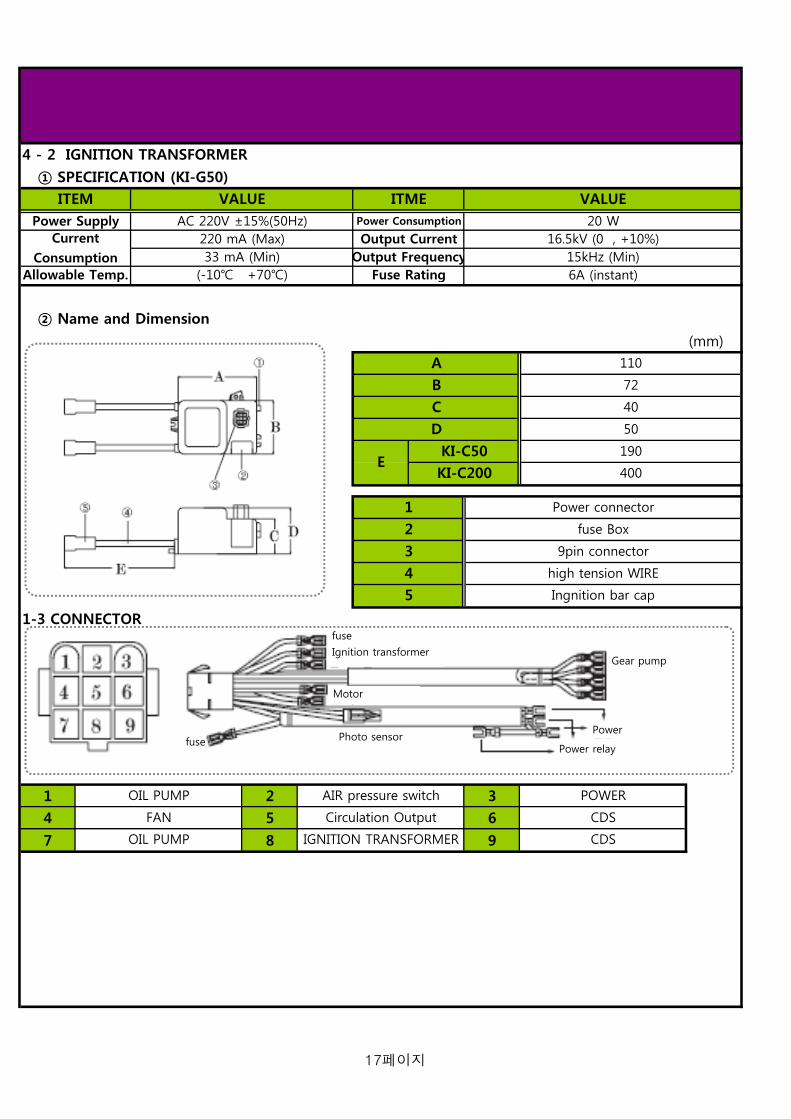
4 - 2 IGNITION TRANSFORMER
① SPECIFICATION (KI-G50)
② Name and Dimension
(mm)
1-3 CONNECTOR
1 2 3
4 5 6
7 8 9
5
CDS
POWEROIL PUMP
CDS
ITEM
Circulation Output
C 40
AC 220V ±15%(50Hz)220 mA (Max)
VALUE
72
33 mA (Min)
A
B
ITME
Allowable Temp.
D
KI-C50
110
VALUE
E190
Power Consumption 20 W
Output FrequencyFuse Rating
Output Current 16.5kV (0 , +10%)
6A (instant)
OIL PUMP IGNITION TRANSFORMER
FAN
AIR pressure switch
KI-C200
2
3
4Ingnition bar cap
400
9pin connector
high tension WIRE
Power Supply
15kHz (Min)
Power connector
fuse Box
1
(-10 +70)
50
CurrentConsumption
Gear pump
Power
Motor
fuse
Ignition transformer
fuse Power relay
Photo sensor
17페이지

4 - 3 IGNITION BAR
SPECIFICATION
Name and Dimension
A 1
B
C 2
D
E 3
F 4
How to adjust the location of ignition rod1. Ignition rod carries 16.5k voltage. Before adjusting,
plug off the power cord.
2. Don't adjust it at your discretion, it is adjusted
minutely out of factory.
3. If necessary, adjust the ignition rod as shown Figure.
4. Epoxy material protects electrode rod and prevent
electrical short. Lots of soot may cause the inter-
mittent ignition fault or ignition delay by electrical
discharges. Therefore, check the soot and epoxy damage.
TIME CHART
Normal combustion Abnormal combustion
Epoxy
93.5
26
14
Ignition transformer
Connection nipple
Ignition rod
Connection hole
Electrode rod
Dielectric Constant
3.5
Φ 11
26
HardnessThermal Resistance
ITEM VALUE ITEM VALUE97 M190
5.3Insulation Resistance
ARC Resistance
18 KV/mm10 14 - 10 15 Ωcm
196 scc
DIMENSION (mm)
Withstanding voltage
NAME
ALARM
TEM/ SENSING
I/G Transformer
Ignition bar
Nozzle adapter
Nozzle
stacilizer
Electric
pumpFlame sensing
sec
ALARM
TEM/ SENSING
I/G Transformer
Electric
pumpFlame sensing
sec
18페이지

The following adjustment and conversion operations must be carried out by qualified personnel. KITURAMI
Limited accepts no liability for damage to property or personal injury resulting from tampering with the boiler by
unauthorized persons.
1. Gas Pressure by Capacity
UNIT
kW
kcal/h
Lit/h
G/H
Quantity
6.8
1EA
7 ∽ 15
Fuel Consumption
70,000
TURBO-100
9.5
50,000
1EA
CTX-7000MV
232.6174.4
TURBO-50 TURBO-70 TURBO-150
Capacity58.1 81.4
20.5 27.2
TURBO-200
116.3
4 - 4 Adjustment and gas Conversion
MODEL
100,000
CTX-7000MV
1EA 1EA
2.0x60˚H/45˚B 3.5x60˚H/45˚B 16.5x60˚H/45˚B
58 kg/h
CTX-7000MV
200,000
13.9
150,000
16.5x60˚H/45˚B
Flame detect Photo tube type Photo tube type Photo tube type Photo tube type Photo tube type
Nozzle
specification
58 kg/h 58 kg/h 58 kg/h
CTX-7000MVCTX-7000MVBurner controller
16.5x60˚H/45˚B
1EA
10 kg/
7 ∽ 15 7 ∽ 15 7 ∽ 15 7 ∽ 15
10 ∽ 70
7 ∽ 12 7 ∽ 12
10 kg/ 10 kg/
7 kg/h 7 kg/h 7 kg/h
10 kg/
Gear Pump
Electronic Pump
10 ∽ 70 10 ∽ 70 10 ∽ 70 10 ∽ 70
10 kg/
58 kg/h
10 kg/ 10 kg/ 10 kg/
5 ∽ 60 5 ∽ 60 5 ∽ 60
7 ∽ 12
19페이지

5. Burner Direction for assembly
NO NO NO
1 2 34 5 67 8 910 11 1213 14 1516 17 1819 20 2122 23 24PHOTO SENSORGAS PECKING
NOZZLE
IGNITION TRANSFORMERBURNER MOTOR
CONNECTOR
POWER RELAY
MORTOR (FRONT)IGNITION BARCYLINDERBURNER GASKET
MOTOR BASE (RIGHT)OIL SUPPLY PIPE
BURNER COVER
NAMENAME
DEMPER
AIR PRESSURE SWITCH
5 - 1 Burner Part exploded view
TUBE ASS'YSTEBILRAIGE
TRANS BRACKET
NAME
FANGEAR PUMP
MOTOR BASE (LEFT)NOZZLE HOLDER
Nozzle fixing
20페이지

6. TEST WORKING
1). Before switching-on, please check the followings after finishing the installation of boiler, flue, pipes, and electricity.
① Is the boiler connected to the boiler-dedicated electrical outlet?
② Are there some combustible materials around the flue?
③ Has the boiler been installed in boiler-dedicated and well ventilated room?
④ Is there enough space for boiler inspection?
⑤ Does the boiler have good drainage on operating?
⑥ Has the boiler been installed horizontally on the nonflammable floor such as concrete floor or bricks?
⑦ Has the boiler's flue been kept warm completely? ⑧ Has the thermostat been connected to lines accurately?
6 - 1 Check list before switching-on
1 2 3 4
5 7 86
21페이지

Date : …….……………………………… Installer : ……………………………………
6 - 2 FIRST IGNITION OPERATION
15. Check the ionisation current
Compleat………………………….
12. Check the working in DHW mode
Compleat………………………….
9. Set the heating power. See section Compleat………………………….
6. Fill the installation. See section Compleat………………………….
3. Check the gas tightness
Compleat………………………….
2. Check the type of gasandchange the gas ifnecessary
5. Check the exhaust fume. See section……
Compleat………………………….
8. Spin the pump.
Compleat………………………….
11. Balance the central heating circuit
Compleat ……………….………
14. Make a combustionrate with once pressing on RESET button during 5sec
1. Check the electricalsupply.
Compleat……………………
4. Measure the gas inlet
Compleat………………………….
7. Check the hydraulic tightness
Compleat………………………….
10. Adapt the requlationat the heating instation
Compleat………………………….
13. Adjust DHW flow rateon the boiler(if necessary)
Compleat………………………….
16. Explain to the enduaer the working of theboiler
Compleat……………………
22페이지

7. Direction for assembly
7 - 1 Boiler Part exploded view
23페이지

7 - 2 Part name
50K 70K 100K 150K 200K
1 Side panel
2 Front panel (UP)
3 Front panel (DOWN)
4 Bottom panel
5 Stainless bend (chimney)
6 Top panel
7 Stainless bend (exchanger)
8 reinforcement panel
9 Damper ring
10 Control box
11 Wire cover
12 reinforcement pipe
13 Heat exchanger
14 Temperature sensor
15 Low water sensor
16 Buffle plate
17 cestabul
18 Power code
19 Room control
20 Mica
21 Peep hole pipe
22 Peep hole cap
23 Gas pipe pecking (peep hole)
24 Exhaust hood
25 Back panel
26 Gasket (burner)
27 Burner ASS'Y
Korean ERP Code
보강 파이프
케이싱 (뒤)
가스켓 (버너)
버 너
감시창 파이프
감시창 캡
가스켓 (감시창
배기후드
감시창
No
저수위센서
보강판넬
Model
파워코드
실내온도조절기
온도센서
주열교환기
버플플레이트
스텐밴드(열교환기)
상부판넬
전면케이싱 (상)
바닥판넬
전면케이신 (하)
케이싱 (좌우)
Part Name (English)
스텐밴드(연통)
담바링
콘트롤박스
전선카바
케스타블
24페이지

8. MAINTENCE GUIDE
8 - 1. Assembly Instructions for Burner
1. Plug off the power cord.
2. Close the Gas valve connected with main gas piping.
3. Disassemble screws fixed on front panel and open
the panel.
1. Separate the connector plug from burner.
2. Remove two nuts on burner flange by spanner.
3. Separate the burner by pulling forward.
1. Replace the gasket fixed on flange with new one.
2. Check the status of Burner (interval and fixed state of
ignition rod) and assemble the burner on flange.
3. Fix the burner by tightening nuts.
4. Assemble the connector plug on the exact location.
1
Tool
25페이지

8 - 2. Assembly Instructions for the Temperature Sensor and Low Water Sensor
1. Plug off the power cord.
2. Close the oil valve connected with the oil tank.
3. Close the valves connected with the heating and hot
water pipes.
4. Loosen screws fixed on front panel and open the panel.
5. Separate the control box and connector plug fixed
on the front of Heat exchanger.
1. Separate Temperature Sensor or Low Water Sensor by
turning it counterclockwise with spanner.
※ Check the scale on the Sensors.
1. After sealing the Sensor by Teflon, Assemble the Sensor
at the exact location by turning clockwise.
2. Connect the Sensor with connector plug.
※ After opening pipe valve, check the water leakage.
3. Assemble the connector plug and control box.
Tool
2
26페이지

8 - 3. How to clean Heat exchager's Exhaust tube
1. Plug off the power cord.
2. Close the oil valve connected with the oil tank.
3. Loosen screws fixed on front panel and open the panel.
4. Loosen screws fixed on the top of Heat exchanger and
separate the panel.
5. Untie stainless band on the flue and separate the flue.
6. Loosen nuts fixed on Damper ring and separate
Damper ring from Exhaust hood.
7. Check the soot status of top of the Heat exchanger and
take Buffle plates out of Exhaust tubes.
8. Clean the soot inside the Exhaust tubes by using brush
or chemical.
9. In reverse order, assemble Heat exchanger.
① Flange of Boiler
② Fixing Bolt
③ Sealing Gasket
④ Flange of Burner
Tool
3
27페이지

9. Functions of the controller
Model : CTX - 4000MV
Parts Description
Displays current water temperature in boiler.
Switch for boiler power On/Off or Restart
Lights when Circulation Pump operates.
Lights when Power is ON.
Cases when Max adjusting is needed
→ When the voltage is too low. (210V)
→ When the emission load in flue is big because the flue is too long or crooked.
Cases when Min adjusting is needed
→ When the voltage is too high. (280V)
→ When the wind pressure into flue is positive.
Lights when Burner operates.
9 - 1 Main Controller part name
1. TEMPERATURE
3. circulationpump
4. Power lamp
2. Power button
6. Burner lamp
5. Ignition RPM Control
1. TEMPERATURE
3. circulation pump
4. Power lamp
2. Power button
6. Burner lamp
5. Ignition RPM Control
28페이지
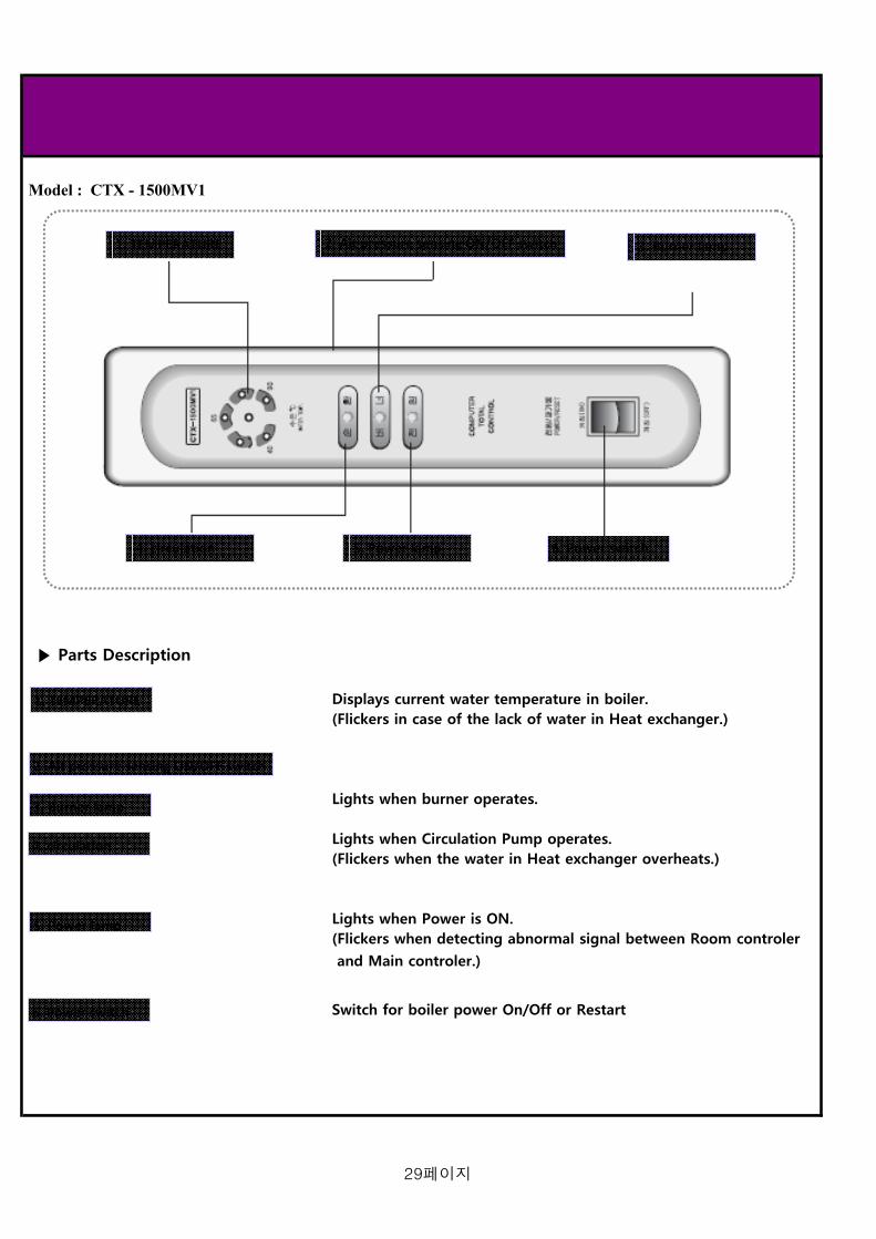
Model : CTX - 1500MV1
Parts Description
Displays current water temperature in boiler.(Flickers in case of the lack of water in Heat exchanger.)
Lights when burner operates.
Lights when Circulation Pump operates.(Flickers when the water in Heat exchanger overheats.)
Lights when Power is ON.(Flickers when detecting abnormal signal between Room controler
and Main controler.)
Switch for boiler power On/Off or Restart
6. Power switch
3. Burner lamp2. Ait pressure sensing ON/OFF switch1. TEMPERATURE
4. circulationpump
5. Power lamp
3. Burner lamp2. Ait pressure sensing ON/OFF switch1. TEMPERATURE
4. circulationpump
5. Power lamp
6. Power switch
3. Burner lamp
2. Ait pressure sensing ON/OFF switch
1. TEMPERATURE
4. circulation
5. Power lamp
29페이지

9 - 2 Room Control panel (CTR-5700 plus)
4
5
6
7
8
9
LEGEND
1. LED panel 2. BOILER HEATING OPERATING CONDITION SELECT BUTTON (RPPM TEMPERATURE HEATING, TIMER HEATING, OUT GOING) 3. DOMESTIC HOT WATER, ONLY 4. GREEN INDICATOR - POWER SUPPLY 5. ADJUSTMENT NUMERIC INCREASING BUTTON EACH EUNCTION 6. ADJUSTMENT NUMERIC DECREASING BUTTON WITH EACH FUNCTION 7. CH TEMPERAYURE ADJUSTMENT BUTTON. 8. TIMER ADJUSTEMENT BUTTON 9. ON/OFF BUTTON
30페이지

9 - 3 Rooom control LED panel
Display Functions
1. When the boiler operates with room temperature heating mode, this symbol display 2. When the boiler operates with room temperature heating mode, this symbol display. 3. Current’s room temperature display in accordance with each heating modes 4. When the boiler operates with timer mode, this symbol display. 5. When the boiler operates with heating temperature mode, adjusted heating temperature display. More the BAR’s numbers, the heating temperature is higher 6. When the boiler is operating in each setting mode, this symbol display 7. When set the room temperature will changing, this symbol display. 8. When the room temperature will be changing, this symbol display 9. When the boiler doesn’t operate with timer mode, this symbol display 10. When the boiler operates with timer heating mode, this symbol display 11. When the boiler operates with outgoing mode, this symbol display. 12. When the boiler operates with DHW mode, this symbol display
31페이지

10. Troubleshooting guide (error code)
Error code The error codes display when errors occur The last ten errors are saved in the appliance error memory → Press the “Timer” button for 5 seconds → Automatically the last errors history display 2 times by step on LCD panel. You can exit the error memory display as follow; → Do not press any button return to the former times display
Code
E 01 Appliance does not start Faults in the gas supply such as
Attempts to ignite during start failed Gas meter or gas pressure detector defective
Air in gas
Gas flow pressure too low
Faults in the gas fitting, wrong gas setting, igniter (ignition
transformer, ignition cable, ignition plug) defective, photo r
sensor defective (cable, electrode), faulty earth in appliance,
electronics defective.
E 02 Flame detect before supplied gas Electronics defective, Photo sensor defective
E 03 Flame goes off during the appliance Gas supply pressure too low, flame detect device defective,
operating until less than 1 minute for PCB defective
5 times repeat
E 04 Interruption in heating temperature sensor Sensor connection defective, sensor faulty
E 05 Interruption safety high limit sensor wire PCB defective, faulty connection on the electronics
E 06 Fan RPM signal doesn’t detect Fan detective, RPM signal connection faulty, PCB defective,
plug not inserted correctly on fan, hall sensor defective
E 07 Fan RPM signal in the wrong range Check the flue condition, PCB defective, electronic defective
E 08 No communication with the PCB Communication faulty between the room controller and the
PCB. PCB faulty, Room controller faulty
E 95 Not enough water in the heating system Filling the water into the heating system
E 96 High temperature limiter actuated Flow probe not connected thermally correct of defective,
appliance does not shut down
※ (In CTR - 1300, 25 LED flickers.)
※ (In CTR - 1300, 25 LED flickers.)
※ (In CTR - 1300, 15 LED flickers.)
※ (In CTR - 1300, 35 LED flickers.)
※ (In CTR - 1300, 25 LED flickers.)
10 - 1 Finding fault
Meaning Cause
32페이지

11. Technical Data Tadle
* Specifications are subject to change without prior notice to improve design and performance
kW( kcal /h)
Li t / h
MI NkW
( kca/h / kg/h)
MAXkW
( kca/h / kg/h)
%
r pm
W
A
V1-V2
I 1- I 2
W
ki t ur ami
st ar
bar ( ps i )
( )
( )
kW( kcal /h)
bar ( ps i )
ℓ /mi n( gpm)
bar ( ps i )
t =25 ℓ /mi n
t =30 ℓ /mi n
t =40 ℓ /mi n
V/Hz
W
Φ
( A)
( A)
W x D x H mm
kg
st age
ModelTechni cal Speci f i cat i on KSO - 50 KSO - 70 KSO - 100 KSO - 200KSO - 150
116. 3( 100, 000)
232. 5( 200, 000)
Heat i ng I nput ( Mi n - Max) 6. 8 9. 5 13. 9 27. 2
Heat i ng Out put ( Max-Mi n) ( Fl ow/Ret ur n 80/ 60)
58. 1( 50, 000)
81. 4( 70, 000)
49 ∽ 75 100 ∽ 150
Combust i on scope
54( 36, 350 / 4. 5)
66( 56, 650 / 5. 5)
93( 79, 980 / 7. 8)
179( 153, 940 / 14. 9)
Heat i ng ar ea ( Mi n - Max) 25 ∽ 37 34 ∽ 52
262( 225, 320 / 21. 9)
Usef ul Ef f i ci ency at Max-Mi n Heat i ngOut put ( Fl ow/Ret ur n 80/ 60)
91. 2 92. 5 92. 1 92. 3
74( 63, 860 / 6. 2)
103( 88, 580 / 8. 6)
203( 174, 580 / 17)
2870 / 3230 3280
155 / 220 155 / 220 0. 23 / 0. 34 0. 43
2880 / 3290 2880 / 3290
0. 73 / 1. 05 1. 2 / 1. 6 2
Mot or condenser 6 450 6 450 6 450
Mot or spec
0. 73 / 1. 05
7 450
I gni t i on t r ansf or mer
el ect r i c pump
kg/ h 7 8
_Regul at i on scope 7 ~ 12 8 ~ 12
Use pr essur e ( kg/) 10 10
Use t emper at ur e ( ) 5 ~ 60 5 ~ 60
GEAR pump
kg/ h 58 58
Use pr essur e ( kg/) 10 10
58 58
Regul at i on scope 7 ~ 15 7 ~ 15 7 ~ 15 7 ~ 15
10 10
Use t emper at ur e ( ) 10 ~ 70 10 ~ 70 10 ~ 70 10 ~ 70
Heat i ng Wat er Ci r cul at i on Met hod Ai r Cl osed & Open Type
Ener gy Per f omance Pur pose Heat i ng and Domest i c Hot Wat er Pr oduct i on
DHW Out put58. 1
( 50, 000)81. 4
( 70, 000)
Max Heat i ng Wat er Pr essur e 3. 0 ( 43. 5) Max Heat i ng Temper at ur e 85 ( 185) Adj us t abl e Temper at ur e Heat i ng 45 - 80 ( 113 ~ 176)
Max Domest i c Hot Wat er Pr essur e 17. 5 ( 253. 8) Speci f i c Domest i c 33. 3 46. 6 66. 7 100
55. 5 83. 3 Ot her Comest i c Hot Wat er Rat e 27. 7 38. 9
45. 8
61. 1 Ot her Comest i c Hot Wat er Rat e 20. 8 29. 1 41. 6
El ect r i cal Suppl y 230V / 50Hz
Power consumpt i on 230 230 380 470300
16. 5x60˚ H/45˚ B 2. 0x60˚ H/45˚ B 3. 5x60˚ H/45˚ B
I nst al l at i on Type FE
I nt ake/Exhaust Fl ue Syst em Type 125 125 195
50 65
Domest i c Hot Wat er Connect i on 20 20 25
Heat i ng wat er Connect i on 40
25
930 x 1820 x 1400
25
930 x 1100 x 1750
Connect i ngDi amet er
65
Physi cal di mensi ons 610 x 1180 x 925 610 x 1350 x 925 740 x 1420 x 1080
40
Bur ner Consumi ng war pot ent i al
f l ame det ect i ng t ype
Cont r ol l er
1. 60 ( 0. 42) Mi n wor ki ng Fl ow Rat e f or DHW
127. 9( 110, 000)
116. 3( 100, 000)
232. 5( 150, 000)
Mi n wor ki ng Pr essur e f or DHW 0. 2 ( 2. 9)
Cont r ol met hod 1 st age 1 st age
Wei ght 180/190 200/210 305/325 650/750
Oi l Type Li ght Oi l
1 st age 1 st age
nozzl e spec
1. 2 / 1. 6
220V - 16. 5kV
0. 2 , 32mA
220V - 16. 5kV
0. 2 , 32mA
220V - 16. 5kV
0. 2 , 32mA
570 / 580
1 st age
58
10
10 ~ 70
320
7 ~ 15
73
6 450
203( 174, 580 / 17)
93( 79, 980 / 7. 8)
200
62. 5
470
CTX-7000MV
173/198 173/198 320
174. 4( 150, 000)
2870 / 3230
0. 23 / 0. 34
75 ∽ 112
20. 5
92. 2
33페이지

12. Memo
34페이지

13. Warranty
35페이지