high efficiency boiler - free boiler manuals efficiency boiler ... boiler control interlock ......
TRANSCRIPT
www.johnsonandstarley.co.uk
sustainable solutions under one roofH E A T I N G H O T W A T E R V E N T I L A T I O N
QUANTEC HR28C ErPHigh Efficiency Boiler
with Passive FlueGas Heat Recovery
Quantec HR28C ErP - G.C. No. 47-416-11
These instructions are to be left with the User
Publication No. ZZ 1430-8June 2016
INSTALLATION, COMMISSIONING& SERVICING INSTRUCTIONS
www.johnsonandstarley.co.uk2
In the interest of continuous development Johnson and Starley reserve the right to change specification without prior notice. Johnson and Starley prides itself on it’s ability to supply spare parts quickly and efficiently.
PLEASE READ THESE INSTRUCTIONS CAREFULLY BEFORE STARTING INSTALLATION. LEAVE THESE INSTRUCTION WITH THE USER OR AT THE GAS METER AFTER INSTALLATION
The Benchmark Scheme Benchmark places responsibilities on both manufacturers and installers. The purpose is to ensure that customers are provided with the correct equipment for their needs, that it is installed, commissioned and serviced in accordance with the manufacturer’s instructions by competent persons and that it meets the requirements of the appropriate Building Regulations. The Benchmark Checklist can be used to demonstrate compliance with Building Regulations and should be provided to the customer for future reference.
Visit www.centralheating.co.uk for more information.
Installers are required to carry out installation, commissioning and servicing work in accordance with the Benchmark Code of Practice which is available from the Heating and Hot water Industry Council who manage and promote the Scheme.
CONTENTS
The Benchmark Scheme 2
1 Features 3
2 General Description 3
3 Building Standards & Regulations 4
4 Safety, Electrical & Gas Information 4General Safety InformationHandling the UnitOperating the ApplianceElectrical SupplyGas Supply
5 Fiche ErP Technical Data 5Technical DataPerformance Data
6 Preparation 8Electrical ConnectionsWater ConnectionsGas ConnectionCondensate DrainBoiler Control InterlockThermostatic Radiator Valves
PositioningTimber Frame BuildingsBathroom InstallationCompartment InstallationsRoom Ventilation
7 Dimension & Clearances 10
8 Heating System 11Expansion VesselPressure GaugePressure Relief ValveFilling LoopPipework SizingDomestic Hot Water RequirementsWater Flow Schematic
9 Installation Instructions 13Carton ContentsWall Mounting TemplateFixing the Appliance
10 Flue Instructions 14Flue ConfigurationDiagram of Terminal PositionsTypes of Flue SystemsFlue Terminal PositionsPlume OutletsFlue Requirements & General InformationConventional 60/100mm Flue Accessories Part No.sOptional Roof OutletsThe Standard Horizontal Flue SystemInstallation of the Standard Horizontal Flue System
11 Condensate Drain 20Use of a Condensate Pump to External TerminationExternal TerminationUnheated Internal Area’s
12 Electrical 21Drop Down Control PanelElectrical ConnectionsInternal WiringTo Add Thermostat/ProgrammerThermostats & Timer KitsOperational System ControlElectrical Testing
13 Wiring Diagram 22
14 Connections & Filling 23Water Connection for Central HeatingCondensate DrainPressure Relief ValveFilling the BoilerGas Connection
15 Commissioning 23Check Gas InstallationAir Purge FunctionInitial LightingCentral HeatingDomestic Hot WaterCheck the Operational Gas Inlet PressureGeneral Checks DHW ModeCH & DHW ModeFlushing the System & Water circulationBalance the SystemWater Temperatures
16 Handing Over 27Instructing the UserLoss of Water Pressure
17 Servicing & Maintenance 27Service ScheduleInitial InspectionServicing SequenceFlue Inspection & ChecksGaining Access to the BoilerControl Panel & Front Door RemovalFan RemovalBurner Assembly RemovalHeat ExchangerCondensate Trap
18 Parts Replacements 30Part Replacements without Draining the SystemDraining the Appliance & System
19 Fault Finding Flowcharts & Blocking Codes 34
20 List of Spares 39
21 Benchmark Checklist and Service Record 41Code of PracticeCommissioning ChecklistService Record
3Sales/Spares & Replacement Help Line 01604 762881
1. FEATURES
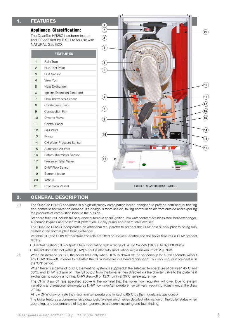
Appliance Classification: The QuanTec HR28C has been tested
and CE certified by B.S.I Ltd for use with NATURAL Gas G20.
2. GENERAL DESCRIPTION
2.1 The QuanTec HR28C appliance is a high efficiency combination boiler, designed to provide both central heating and domestic hot water on demand. It’s design is room sealed, taking combustion air from outside and expelling the products of combustion back to the outside.
Standard features include full sequence automatic spark ignition, low water content stainless steel heat exchanger, automatic bypass and boiler frost protection, a daily pump and divert valve excises.
The QuanTec HR28C incorporates an additional recuperator to preheat the DHW cold supply prior to being fully heated in the normal plate heat exchanger.
Variable CH and DHW temperature controls are fitted on the user control and the boiler features a DHW preheat facility.
• Central heating (CH) output is fully modulating with a range of: 4.8 to 24.2kW (16,500 to 82,600 Btu/h)
• Instant domestic hot water (DHW) output is also fully modulating with a maximum of: 23.07kW.
2.2 When no demand for CH, the boiler fires only when DHW is drawn off, or periodically for a few seconds without any DHW draw-off, in order to maintain the DHW calorifier in a heated condition. This only occurs if pre-heat is in the ‘ON’ period.
When there is a demand for CH, the heating system is supplied at the selected temperature of between 45°C and 80°C, until DHW is drawn off. The full output from the boiler is then directed via the diverter valve to the plate heat exchanger to supply a nominal DHW draw-off of 12.31 l/min at 35°C temperature rise.
The DHW draw off rate specified above is the nominal that the boiler flow regulator will give. Due to system variations and seasonal temperatures DHW flow rates/temperature rise will vary, requiring adjustment at the draw off tap.
At low DHW draw-off rate the maximum temperature is limited to 65°C by the modulating gas control.
The boiler features a comprehensive diagnostic system which gives detailed information on the boiler status when operating, and performance of key components to aid commissioning and fault finding.
FEATURES
1 Rain Trap
2 Flue Test Point
3 Flue Sensor
4 View Port
5 Heat Exchanger
6 Ignition/Detection Electrode
7 Flow Thermistor Sensor
8 Condensate Trap
9 Combustion Fan
10 Diverter Valve
11 Control Panel
12 Gas Valve
13 Pump
14 CH Water Pressure Sensor
15 Automatic Air Vent
16 Return Thermistor Sensor
17 Pressure Relief Valve
18 DHW Flow Sensor
19 Burner Injector
20 Venturi
21 Expansion Vessel FIGURE 1. QUANTEC HR28C FEATURES
20
11
19
18
16
17
15
14
13
12
2
3
5
1
4
7
6
10
9
8
www.johnsonandstarley.co.uk4
3. BUILDING STANDARDS & REGULATIONS
STATUTE LAW DEFINES THAT ALL GAS APPLIANCES MUST BE INSTALLED BY COMPETENT PERSONS, i.e. GAS SAFE REGISTERED INSTALLERS.
GAS SAFE MEMBERSHIP ENQUIRIES TEL: 0800 408 5500 IN ACCORDANCE WITH THE GAS SAFETY (INSTALLATION AND USE) REGULATIONS (CURRENT EDITION).
FAILURE TO COMPLY WITH THESE REGULATIONS MAY LEAD TO PROSECUTION.
3.1 INSTALLATION REGULATIONS
• Building Standards (Scotland) (Consolidation) Regulations
• Building Regulation Part L
• Gas Safety (Installation and Use) Regulations (as amended)
• The Water Fittings Regulations or Water by-laws in Scotland
• Building Regulation (Northern Ireland)
• Model and Local Authority Byelaws
• Health & Safety Document No. 635.
• The Electricity at Work Regulations, 1989.
• Institute of Electrical Engineers (I.E.E) Wiring Regulations
• EU Regulation No 811/2013 and No. 812/2013 supplement Directive 2013/20/EU
This appliance has been Tested and Certified in order to meet the necessary European Directives and comply with the latest Building Regulations, including the efficiency requirements of the SEDBUK scheme.
• Efficiency of Hot Water Boilers Directive 92/42/EEC
• Gas Appliance Directive 2009/142/EC
• Low Voltage Directive 2006/95/EEC
• Electromagnetic Compatibility Directive 93/68/EEC
3.2 BUILDING STANDARDS AND REGULATIONSWhere no specific instructions are given, reference should be made to the relevant British Standard Code of Practice.
BS 5440:1 Flues (for gas appliances of rated input not exceeding 70 kW).
BS 5440:2 Ventilation (for gas appliances of rated input not exceeding 70 kW).
BS EN 12828 Heating Systems in buildings: Design for water based heating systems.
BS EN 12831 Heating Systems in buildings: Method for calculation of the design heat load.
BS EN 14336 Heating Systems in buildings: Installation and commissioning of water based heating systems.
BS 5546 Installation of gas hot water supplies for domestic purposes (2nd Family Gases)
BS 6798 Installation of gas fired hot water boilers of rated input not exceeding 70 kW.
BS 6891 Installation of Low Pressure Gas Pipework of up to 28 mm (R1) in domestic premises (2nd family gases).
IMPORTANT: This appliance is CE certificated for safety and performance. It is important that no modifications are made to this appliance, unless fully approved in writing by Johnson & Starley Ltd. If in doubt please ring Johnson & Starley Ltd on Telephone 01604 762881.
4. SAFETY ELECTRICAL & GAS INFORMATION
PLEASE READ THESE INSTRUCTIONS CAREFULLY BEFORE COMMENCING WITH THE INSTALLATION
4.1 GENERAL SAFETY INFORMATION4.1.1 An LPG unit should not be installed in a room or internal space below ground level unless one side of the sides
of the building is open to the ground.
4.1.2 Only use QuanTec original spare parts on this appliance. Failure to do so will invalidate the guarantee.
4.1.3 No artificially softened water must not be used to fill the central heating system.
4.1.4 The system can be damaged by debris entering the heat exchanger and reduce efficiency. It is recommended that the boiler is flushed, follow these guidelines as this will protect the boiler and prolong its life.
4.1.5 It is important that the system is flushed thoroughly before the appliance is left to operate (as recommended in BS 7593) in order to maintain an efficiently operating heating system. For replacement installations, the system MUST be flushed with the old boiler in situ, in order to prevent the QuanTec becoming a trap for system debris. Once the system has been flushed, an inhibitor (suitable for stainless steel heat exchangers) should be added. Appropriate inhibitors are available, for example Sentinel, Fernox and Salamader. We also recommend a Magnetic & Non Magnetic Filtration system is fitted between the last radiator and the boiler.
4.1.6 Failure to carry out the above procedure will invalidate the guarantee!
5Sales/Spares & Replacement Help Line 01604 762881
GAS LEAKS
DO NOT OPERATE ANY ELECTRICAL SWITCHES, OR USE A NAKED FLAME TURN OFF THE GAS SUPPLY. VENTILATE THE AREA BY OPENING DOORS AND
WINDOWS. CALL THE NATIONAL GAS EMERGENCY SERVICE ON
0800 111999
4.2 HANDLING THE UNIT4.2.1 The weight of this appliance exceeds that recommended for a one-man lift. It will therefore be necessary to gain
assistance at times during the removal from its packaging and during installation procedure. Manoeuvring the boiler may include the use of a sack truck and involve lifting, pushing and pulling.
4.2.2 It should be noted that this appliance may contain sharp edges. Care MUST be taken when handling the appliance to prevent injury. We advise the engineer to wear suitable P.P.E.
4.2.3 Once the appliance has been fired beware that certain parts will be hot to the touch.
4.2.4 Do not install flues during rain, high winds or in severe weather conditions.
4.2.5 The manufacturers instructions supplied must not be taken as overriding any statutory requirements.
4.3 OPERATING THE APPLIANCE4.3.1 This appliance is not intended for use by persons (including children) with reduced physical, sensory or mental
capabilities, or lack of experience and knowledge, unless they have supervision or been given instruction concerning use of the appliance by a person responsible for their safety.
4.3.2 Children should be supervised to ensure they do not play with the appliance.
4.4 ELECTRICAL SUPPLY4.4.1 Ensure the mains supply voltage, frequency, number of phases and power rating comply with details on the rating label.
4.4.2 All wiring must be in accordance with the appropriate standards. The equipment must be supplied with a double pole isolator switch and for new heating systems, and where practical replacement installations, the isolator shall be situated adjacent to the appliance.
4.4.3 Ensure safety regulations and practices are adhered to when installing and using this appliance.
4.5 GAS SUPPLY4.3.1 It is the responsibility of the Gas Installer to size the gas installation pipework in accordance with BS 6891. Whilst
the principle of the 1:1 gas valve ensures the QuanTec range is able to deliver it’s full output at inlet pressures as low as 14mb, other gas appliances in the property may not be as tolerant. When operating pressures are found to be below the minimum meter outlet of 19mb these should be checked to ensure this is adequate for correct and safe operation.
4.3.2 Allowing for the acceptable pressure loss of 1mb across the installation pipework, it can be assumed that a mini-mum permitted operating pressure of 18mb will be delivered to the inlet of the appliance. (Reference BS 6400-1 Clause 6.2 Pressure Absorption).
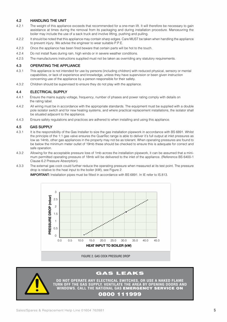
4.3.3 The external gas cock could further reduce the operating pressure when measured at its test point. The pressure drop is relative to the heat input to the boiler (kW), see Figure 2.
IMPORTANT: Installation pipes must be fitted in accordance with BS 6891. In IE refer to IS.813.
FIGURE 2. GAS COCK PRESSURE DROP
3
2.5
2
1.5
1
0.5
0
PR
ES
SU
RE
DR
OP
(mba
r)
0.0 0.5 10.0 15.0 20.0 25.0 30.0 35.0 40.0 45.0
HEAT INPUT TO BOILER (kW)
www.johnsonandstarley.co.uk6
5. TECHNICAL DATA
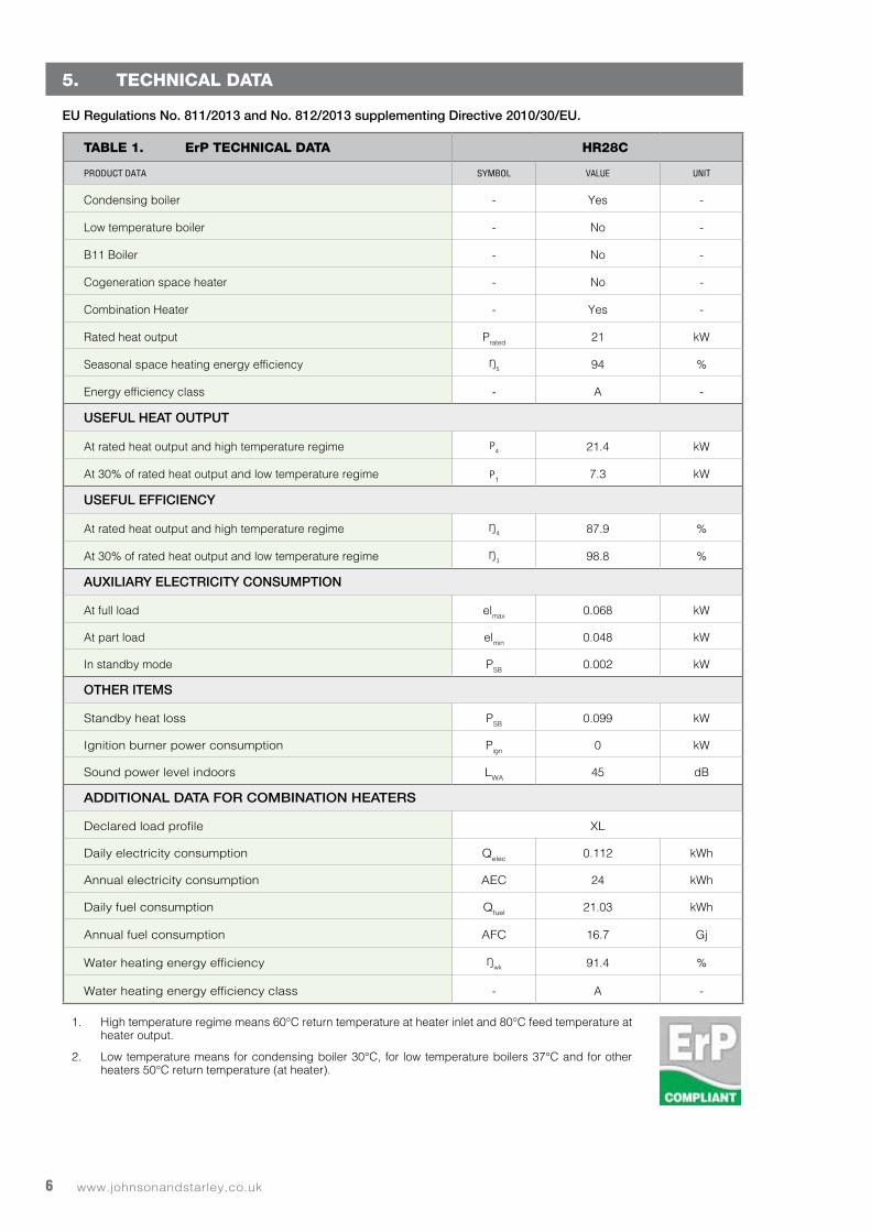
EU Regulations No. 811/2013 and No. 812/2013 supplementing Directive 2010/30/EU.
TABLE 1. ErP TECHNICAL DATA HR28C
PRODUCT DATA SYMBOL VALUE UNIT
Condensing boiler - Yes -
Low temperature boiler - No -
B11 Boiler - No -
Cogeneration space heater - No -
Combination Heater - Yes -
Rated heat output Prated 21 kW
Seasonal space heating energy efficiency ŊS 94 %
Energy efficiency class - A -
USEFUL HEAT OUTPUT
At rated heat output and high temperature regime P4 21.4 kW
At 30% of rated heat output and low temperature regime P1 7.3 kW
USEFUL EFFICIENCY
At rated heat output and high temperature regime Ŋ4 87.9 %
At 30% of rated heat output and low temperature regime Ŋ1 98.8 %
AUXILIARY ELECTRICITY CONSUMPTION
At full load elmax 0.068 kW
At part load elmin 0.048 kW
In standby mode PSB 0.002 kW
OTHER ITEMS
Standby heat loss PSB 0.099 kW
Ignition burner power consumption Pign 0 kW
Sound power level indoors LWA 45 dB
ADDITIONAL DATA FOR COMBINATION HEATERS
Declared load profile XL
Daily electricity consumption Qelec 0.112 kWh
Annual electricity consumption AEC 24 kWh
Daily fuel consumption Qfuel 21.03 kWh
Annual fuel consumption AFC 16.7 Gj
Water heating energy efficiency Ŋwk 91.4 %
Water heating energy efficiency class - A -
1. High temperature regime means 60°C return temperature at heater inlet and 80°C feed temperature at heater output.
2. Low temperature means for condensing boiler 30°C, for low temperature boilers 37°C and for other heaters 50°C return temperature (at heater).
7Sales/Spares & Replacement Help Line 01604 762881
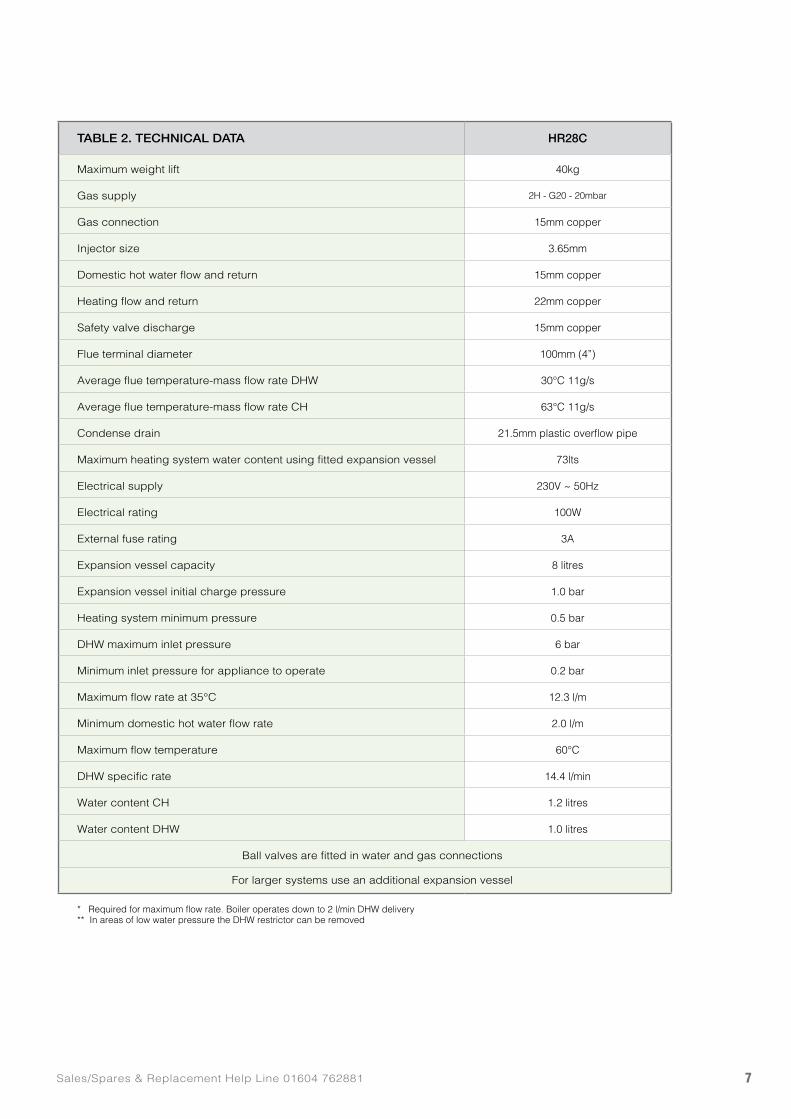
TABLE 2. TECHNICAL DATA HR28C
Maximum weight lift 40kg
Gas supply 2H - G20 - 20mbar
Gas connection 15mm copper
Injector size 3.65mm
Domestic hot water flow and return 15mm copper
Heating flow and return 22mm copper
Safety valve discharge 15mm copper
Flue terminal diameter 100mm (4”)
Average flue temperature-mass flow rate DHW 30°C 11g/s
Average flue temperature-mass flow rate CH 63°C 11g/s
Condense drain 21.5mm plastic overflow pipe
Maximum heating system water content using fitted expansion vessel 73lts
Electrical supply 230V ~ 50Hz
Electrical rating 100W
External fuse rating 3A
Expansion vessel capacity 8 litres
Expansion vessel initial charge pressure 1.0 bar
Heating system minimum pressure 0.5 bar
DHW maximum inlet pressure 6 bar
Minimum inlet pressure for appliance to operate 0.2 bar
Maximum flow rate at 35°C 12.3 l/m
Minimum domestic hot water flow rate 2.0 l/m
Maximum flow temperature 60°C
DHW specific rate 14.4 l/min
Water content CH 1.2 litres
Water content DHW 1.0 litres
Ball valves are fitted in water and gas connections
For larger systems use an additional expansion vessel
* Required for maximum flow rate. Boiler operates down to 2 l/min DHW delivery** In areas of low water pressure the DHW restrictor can be removed
www.johnsonandstarley.co.uk8
6. PREPARATION & POSITIONING
6.1 PREPARATION6.1.1 ELECTRICAL CONNECTIONS: Make sure all the electrical cables are in place.
6.1.2 WATER CONNECTIONS: Important. A minimum length of 1 metre of copper pipe MUST be fitted to both flow and return connections from the boiler before connection to any plastic piping.
6.1.3 The central heating system should be in accordance with BS 6798 and for small bore and microbore systems, BS 5449.
6.1.4 It is important that the system is flushed thoroughly before the appliance is left to operate (as recommended in BS 7593) in order to maintain an efficiently operating heating system and in accordance with the Benchmark Guidance Notes on Water Treatment in Central Heating Systems. See paragraph 15.10.
6.1.5 GAS CONNECTIONS: Make sure the gas connections are in place.
6.1.6 Give consideration to the flue position. Pluming will occur at the terminal so terminal positions where this could cause a nuisance should be avoided. See Figure 11.
6.1.7 Give consideration to the overall height. See section 7.
6.1.8 CONDENSE DRAIN: This drain must be connected to a drainage point on site. All pipework and fittings in the condensate drainage system MUST be made of plastic - no other materials may be used.
IMPORTANT: Any external runs must be in accordance with BS 6798. The drain outlet on the boiler is sized for standard 21.5mm (¾”) overflow pipe.
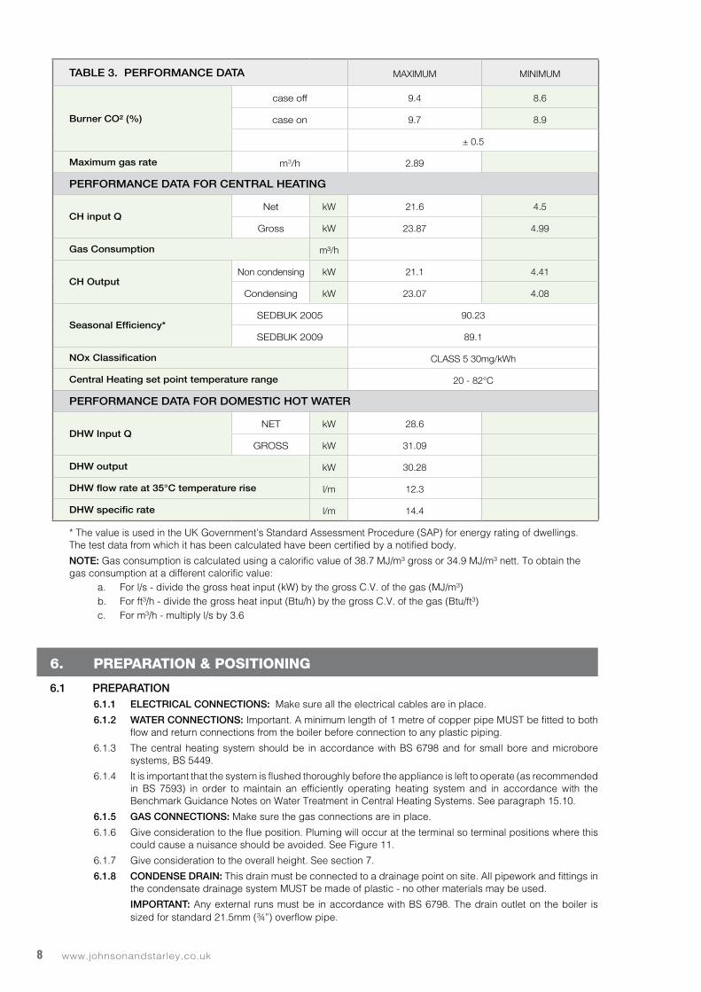
TABLE 3. PERFORMANCE DATA MAXIMUM MINIMUM
Burner CO² (%)
case off 9.4 8.6
case on 9.7 8.9
± 0.5
Maximum gas rate m3/h 2.89
PERFORMANCE DATA FOR CENTRAL HEATING
CH input QNet kW 21.6 4.5
Gross kW 23.87 4.99
Gas Consumption m³/h
CH OutputNon condensing kW 21.1 4.41
Condensing kW 23.07 4.08
Seasonal Efficiency*SEDBUK 2005 90.23
SEDBUK 2009 89.1
NOx Classification CLASS 5 30mg/kWh
Central Heating set point temperature range 20 - 82°C
PERFORMANCE DATA FOR DOMESTIC HOT WATER
DHW Input QNET kW 28.6
GROSS kW 31.09
DHW output kW 30.28
DHW flow rate at 35°C temperature rise l/m 12.3
DHW specific rate l/m 14.4
* The value is used in the UK Government’s Standard Assessment Procedure (SAP) for energy rating of dwellings. The test data from which it has been calculated have been certified by a notified body.
NOTE: Gas consumption is calculated using a calorific value of 38.7 MJ/m³ gross or 34.9 MJ/m³ nett. To obtain the gas consumption at a different calorific value:
a. For l/s - divide the gross heat input (kW) by the gross C.V. of the gas (MJ/m³)b. For ft³/h - divide the gross heat input (Btu/h) by the gross C.V. of the gas (Btu/ft³)c. For m³/h - multiply l/s by 3.6
9Sales/Spares & Replacement Help Line 01604 762881
6.1.9 BOILER CONTROL INTERLOCK: Central heating system controls should be installed to ensure the boiler is switched off when there is no demand for heating, in compliance with Building Regulations.
6.1.10 THERMOSTATIC RADIATOR VALVES: Central heating systems utilising thermostatic radiator valve controls in individual rooms, need one space heating temperature control over a living/dining area or hallway having a heating requirement of at least 10% of the minimum boiler heat output with a minimum 500W radiator, which should be achieved using a room thermostat. However, if the system employs thermostatic radiator valves on all radiators, or two port valves, then a bypass circuit must be fitted with an automatic bypass valve to ensure minimum flow is maintained.
6.2 POSITIONING6.2.1 The boiler must be installed on a flat and vertical internal wall, capable of adequately supporting the
weight of the boiler and any ancillary equipment.
6.2.2 The appliance is not suitable for external installation unless it is protected from the elements in a suitable enclosure. The enclosure must provide the required clearances for installation, servicing and maintenance as well as the correct level of ventilation. The selected position should allow for a suitable flue system to be installed.
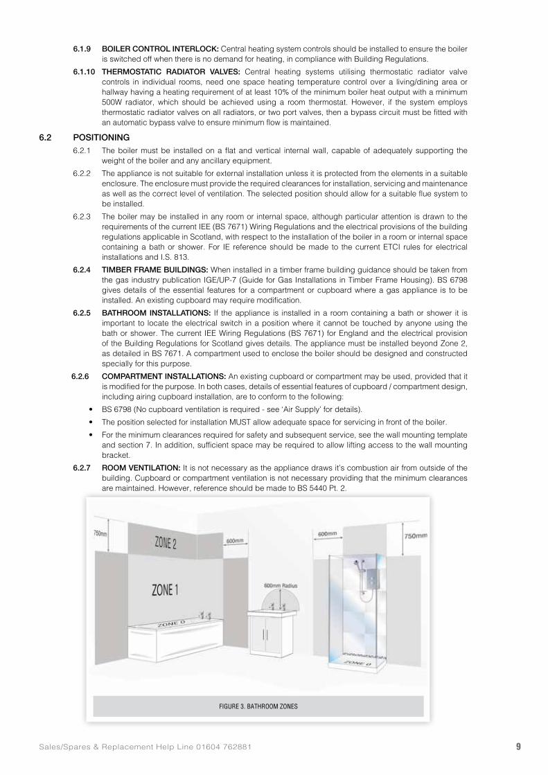
6.2.3 The boiler may be installed in any room or internal space, although particular attention is drawn to the requirements of the current IEE (BS 7671) Wiring Regulations and the electrical provisions of the building regulations applicable in Scotland, with respect to the installation of the boiler in a room or internal space containing a bath or shower. For IE reference should be made to the current ETCI rules for electrical installations and I.S. 813.
6.2.4 TIMBER FRAME BUILDINGS: When installed in a timber frame building guidance should be taken from the gas industry publication IGE/UP-7 (Guide for Gas Installations in Timber Frame Housing). BS 6798 gives details of the essential features for a compartment or cupboard where a gas appliance is to be installed. An existing cupboard may require modification.
6.2.5 BATHROOM INSTALLATIONS: If the appliance is installed in a room containing a bath or shower it is important to locate the electrical switch in a position where it cannot be touched by anyone using the bath or shower. The current IEE Wiring Regulations (BS 7671) for England and the electrical provision of the Building Regulations for Scotland gives details. The appliance must be installed beyond Zone 2, as detailed in BS 7671. A compartment used to enclose the boiler should be designed and constructed specially for this purpose.
6.2.6 COMPARTMENT INSTALLATIONS: An existing cupboard or compartment may be used, provided that it is modified for the purpose. In both cases, details of essential features of cupboard / compartment design, including airing cupboard installation, are to conform to the following:
• BS 6798 (No cupboard ventilation is required - see ‘Air Supply’ for details).
• The position selected for installation MUST allow adequate space for servicing in front of the boiler.
• For the minimum clearances required for safety and subsequent service, see the wall mounting template and section 7. In addition, sufficient space may be required to allow lifting access to the wall mounting bracket.
6.2.7 ROOM VENTILATION: It is not necessary as the appliance draws it’s combustion air from outside of the building. Cupboard or compartment ventilation is not necessary providing that the minimum clearances are maintained. However, reference should be made to BS 5440 Pt. 2.
FIGURE 3. BATHROOM ZONES
www.johnsonandstarley.co.uk10
7. DIMENSIONS & CLEARANCES
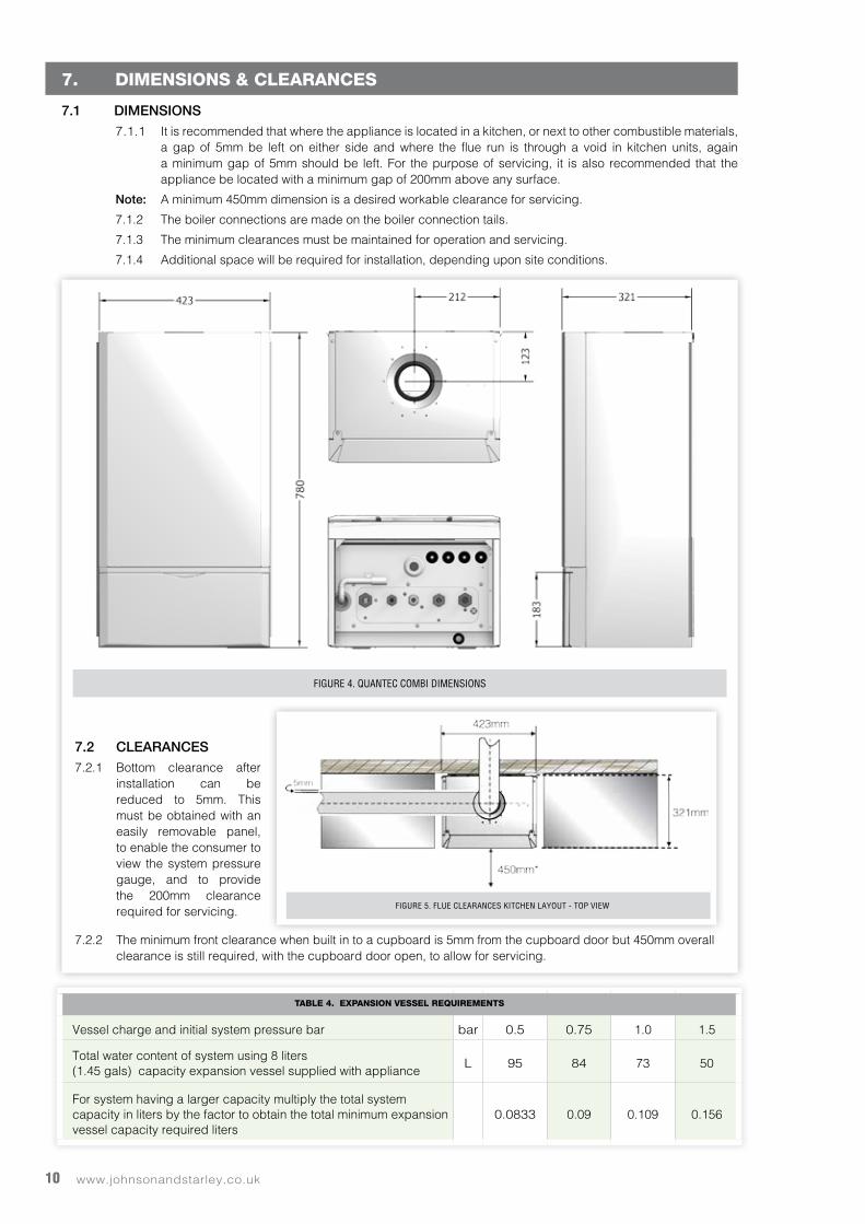
7.1 DIMENSIONS7.1.1 It is recommended that where the appliance is located in a kitchen, or next to other combustible materials,
a gap of 5mm be left on either side and where the flue run is through a void in kitchen units, again a minimum gap of 5mm should be left. For the purpose of servicing, it is also recommended that the appliance be located with a minimum gap of 200mm above any surface.
Note: A minimum 450mm dimension is a desired workable clearance for servicing.
7.1.2 The boiler connections are made on the boiler connection tails.
7.1.3 The minimum clearances must be maintained for operation and servicing.
7.1.4 Additional space will be required for installation, depending upon site conditions.
7.2 CLEARANCES7.2.1 Bottom clearance after
installation can be reduced to 5mm. This must be obtained with an easily removable panel, to enable the consumer to view the system pressure gauge, and to provide the 200mm clearance required for servicing.
7.2.2 The minimum front clearance when built in to a cupboard is 5mm from the cupboard door but 450mm overall clearance is still required, with the cupboard door open, to allow for servicing.
FIGURE 4. QUANTEC COMBI DIMENSIONS
FIGURE 5. FLUE CLEARANCES KITCHEN LAYOUT - TOP VIEW
TABLE 4. EXPANSION VESSEL REQUIREMENTS
Vessel charge and initial system pressure bar bar 0.5 0.75 1.0 1.5
Total water content of system using 8 liters(1.45 gals) capacity expansion vessel supplied with appliance
L 95 84 73 50
For system having a larger capacity multiply the total system capacity in liters by the factor to obtain the total minimum expansion vessel capacity required liters
0.0833 0.09 0.109 0.156
11Sales/Spares & Replacement Help Line 01604 762881
8. HEATING SYSTEM
8.1 The installation must comply with all relevant national and local regulations.
All components of the system must be suitable for a working pressure of 3 bar and temperature of 110°C. Extra care should be taken in making all connections so that the risk of leakage is minimised.
NOTE: a. The method of filling, refilling, topping up or flushing sealed primary hot water circuits from the mains via a temporary hose connection is only allowed if acceptable to the local water authority.
b. Antifreeze fluid, corrosion and scale inhibitor fluids suitable for use with boilers having stainless steel heat exchangers may be used in the central heating system.
8.2 EXPANSION VESSEL: The integral expansion vessel is pre-charged to a pressure of between 0.5 and 1.0 bar. This should be checked before the water system is filled. Table 3 show the water system volume that is acceptable for this vessel. If the system water volume is larger then an additional vessel must be fitted to the system. BS 5449 and BS 6798 gives further details regarding expansion vessel sizing and sealed systems. See Table 3.
8.3 PRESSURE GAUGE: The appliance has two components that monitor pressure. Firstly there is a mechanical pressure gauge on the CH flow outlet, this allows the heating system to be pre-plumbed and filled with a visual check on the pressure. The second is an electronic device used by the microprocessor control to monitor the system pressure and block the heat input, should there be a lack of pressure.
8.4 PRESSURE RELIEF VALVE: The pressure relief valve protects the system from over pressurisation. It is set to be fully open at 3 bar, however it will start to open at approximately 2.7 bar. It should not be used to flush the system. Using no less than 15mm diameter copper pipe, the discharge pipe must be extended to a safe place outside the building. The discharge position must be visible, not onto a public access area or above any window or entrance. The pipe must have a continuous fall and discharge to a safe place. It is possible that boiling water and/or steam could be discharged if the safety valve operates.
8.5 FILLING LOOP: The group set incorporates a filling loop that temporarily connects the DHW supply to the CH system. This is used to fill the CH system on installation and whenever the water pressure has been removed for system modifications, etc. The filling loop complies with the water supply (water fittings) regulations 1999 Section G24.1 and G24.2. After filling the system the hose should be disconnected and stored in a safe place for future use.
8.6 PIPEWORK SIZING: In order to keep the noise of the system to a minimum, the velocity of water should be kept below 1.5m/s and it should be noted that the appliance is designed to operate with a temperature differential of 20˚C between flow and return. The maximum flow rates are 0.3 kg/s which, through a 22mm pipe, gives velocities of 1.00m/s. Therefore, the recommended minimum pipe size for the main carcass is 22mm.
8.7 DOMESTIC HOT WATER SYSTEM REQUIREMENTS The DHW service must be in accordance with BS 5546 & BS 6700.
8.7.1 Domestic hot water circuits and their components, must be in accordance with the relevant standards and water supply regulations. Further guidance/recommendations can be found in building regulations G17 to 24 and R17 to 24.
8.7.2 The maximum domestic cold water supply pressure allowable for this appliance is 5 bar. If the supply pressure exceeds this, a pressure-reducing valve must be installed in the supply to the appliance.
8.7.3 If the water to the property is “hard”, more than 200ppm of salts, then a scale inhibitor should be fitted. Such products are available from Salamander.
NOTE: The system must not be filled with ‘softened’ water. The cold water filling position should be before any softening product.
8.7.4 In areas of low mains water pressures the domestic hot water regulator may be removed from the DHW flow turbine cartridge. The boiler will require the flow rate to be set to obtain a temperature rise of 35°C at the tap furthest from the boiler.
8.7.5 The boilers are suitable for connection to most types of washing machine and dishwasher appliances.
8.7.6. When connecting to suitable showers, ensure that:
a. The cold inlet to the boiler is fitted with an approved anti-vacuum or syphon non-return valve.
b. Hot and cold water supplies to the shower are of equal pressure.
IMPORTANT: Provision must be made to accommodate the expansion of DHW contained within the appliance. If the DHW inlet contains a back flow prevention device or non-return valve, e.g. A water meter, then a mini expansion vessel should be fitted between the device and the boiler in the cold inlet pipe.
www.johnsonandstarley.co.uk12
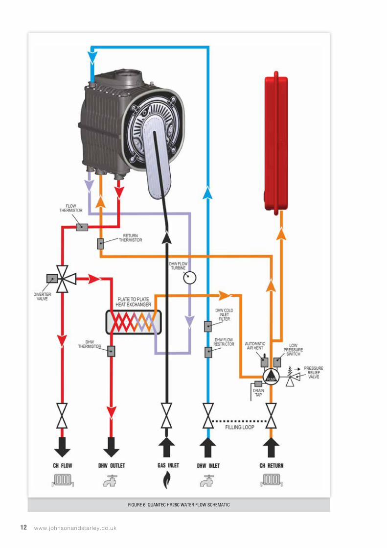
FIGURE 6. QUANTEC HR28C WATER FLOW SCHEMATIC
13Sales/Spares & Replacement Help Line 01604 762881
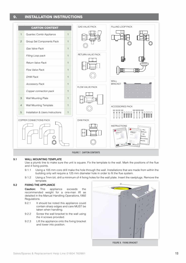
FIGURE 7. CARTON CONTENTS
9. INSTALLATION INSTRUCTIONS
9.1 WALL MOUNTING TEMPLATE Use a plumb line to make sure the unit is square. Fix the template to the wall. Mark the positions of the flue
and 4 fixing points.
9.1.1 Using a 105 mm core drill make the hole through the wall. Installations that are made from within the building only will require a 125 mm diameter hole in order to fit the flue system.
9.1.2 Using a 7mm bit, drill a minimum of 4 fixing holes for the wall plate. Insert the rawlplugs. Remove the template.
9.2 FIXING THE APPLIANCE
Caution: This appliance exceeds the recommended weight for a one-man lift as detailed in the Manual Handling Operations,1992 Regulations.
9.2.1 It should be noted this appliance could contain sharp edges and care MUST be taken when handling.
9.2.2 Screw the wall bracket to the wall using the 4 screws provided.
9.2.3 Lift the appliance onto the fixing bracket and lower into position.
FIGURE 8. FIXING BRACKET
FILLING LOOP PACKGAS VALVE PACK
COPPER CONNECTIONS PACK
RETURN VALVE PACK
FLOW VALVE PACK
ACCESSORIES PACK
WALLBRACKET
DHW PACK
CARTON CONTENT
1 Quantec Combi Appliance 1
2 Group Set Components Pack 1
Gas Valve Pack 1
Filling Loop pack 1
Return Valve Pack 1
Flow Valve Pack 1
DHW Pack 1
Accessory Pack 1
Copper connection pack 1
3 Wall Mounting Plate 1
4 Wall Mounting Template 1
5 Installation & Users Instructions 1
INSTRUCTIONS
WALLTEMPLATE
FORQUANTEC
COMBI & SYSTEMBOILERS
www.johnsonandstarley.co.uk14
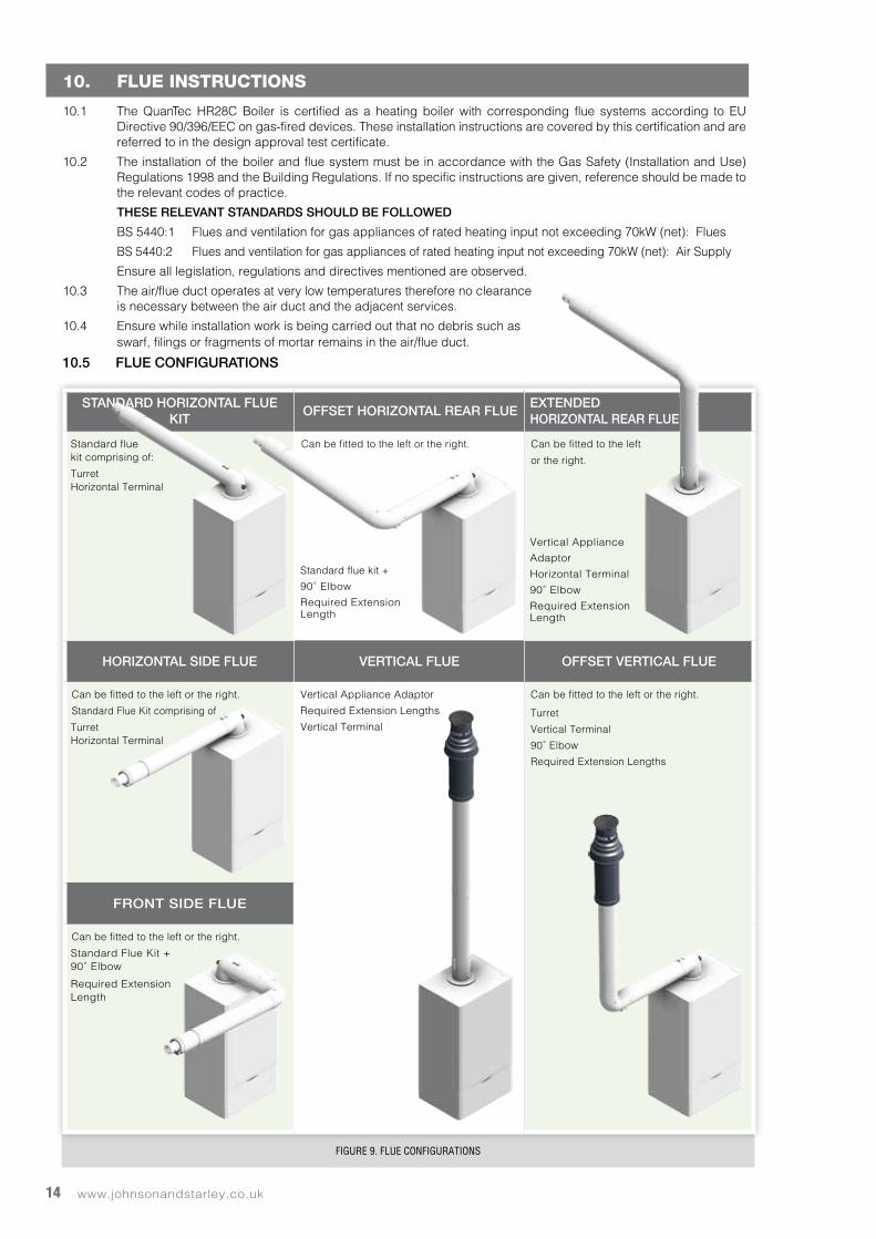
FIGURE 9. FLUE CONFIGURATIONS
STANDARD HORIZONTAL FLUE KIT
OFFSET HORIZONTAL REAR FLUEEXTENDED HORIZONTAL REAR FLUE
Standard fluekit comprising of:
TurretHorizontal Terminal
Can be fitted to the left or the right.
Standard flue kit +
90˚ Elbow
Required ExtensionLength
Can be fitted to the left
or the right.
Vertical Appliance
Adaptor
Horizontal Terminal
90˚ Elbow
Required ExtensionLength
HORIZONTAL SIDE FLUE VERTICAL FLUE OFFSET VERTICAL FLUE
Can be fitted to the left or the right.
Standard Flue Kit comprising of
TurretHorizontal Terminal
Vertical Appliance Adaptor
Required Extension Lengths
Vertical Terminal
Can be fitted to the left or the right.
Turret
Vertical Terminal
90˚ Elbow
Required Extension Lengths
FRONT SIDE FLUE
Can be fitted to the left or the right.
Standard Flue Kit +90˚ Elbow
Required ExtensionLength
10. FLUE INSTRUCTIONS
10.1 The QuanTec HR28C Boiler is certified as a heating boiler with corresponding flue systems according to EU Directive 90/396/EEC on gas-fired devices. These installation instructions are covered by this certification and are referred to in the design approval test certificate.
10.2 The installation of the boiler and flue system must be in accordance with the Gas Safety (Installation and Use) Regulations 1998 and the Building Regulations. If no specific instructions are given, reference should be made to the relevant codes of practice.
THESE RELEVANT STANDARDS SHOULD BE FOLLOWED
BS 5440:1 Flues and ventilation for gas appliances of rated heating input not exceeding 70kW (net): Flues
BS 5440:2 Flues and ventilation for gas appliances of rated heating input not exceeding 70kW (net): Air Supply
Ensure all legislation, regulations and directives mentioned are observed.
10.3 The air/flue duct operates at very low temperatures therefore no clearance is necessary between the air duct and the adjacent services.
10.4 Ensure while installation work is being carried out that no debris such as swarf, filings or fragments of mortar remains in the air/flue duct.
10.5 FLUE CONFIGURATIONS
15Sales/Spares & Replacement Help Line 01604 762881
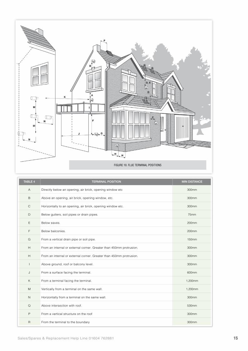
FIGURE 10. FLUE TERMINAL POSITIONS
TABLE 4 TERMINAL POSITION MIN DISTANCE
A Directly below an opening, air brick, opening window etc 300mm
B Above an opening, air brick, opening window, etc. 300mm
C Horizontally to an opening, air brick, opening window etc. 300mm
D Below gutters, soil pipes or drain pipes. 75mm
E Below eaves. 200mm
F Below balconies. 200mm
G From a vertical drain pipe or soil pipe. 150mm
H From an internal or external corner. Greater than 450mm protrusion. 300mm
H From an internal or external corner. Greater than 450mm protrusion. 300mm
I Above ground, roof or balcony level. 300mm
J From a surface facing the terminal. 600mm
K From a terminal facing the terminal. 1,200mm
M Vertically from a terminal on the same wall. 1,200mm
N Horizontally from a terminal on the same wall. 300mm
Q Above intersection with roof. 530mm
P From a vertical structure on the roof 300mm
R From the terminal to the boundary 300mm
www.johnsonandstarley.co.uk16
10.6 TYPE OF FLUE SYSTEMS10.6.1 The standard concentric flue system 60/100mm (100mm diameter).
10.6.2 A Flexible flue kit (FFK-5) 60/100mm (100mm diameter). For further information contact the sales office at Johnson & Starley Ltd. Telephone 01604 762881.
10.6.3 The air/flue duct operates at very low temperatures therefore no clearance is necessary between the air duct and the adjacent services.
10.7 FLUE TERMINAL POSITIONS10.7.1 The following information provides the general requirements for siting flue terminals. As part of the
recommendation given in BS 1550 Part 1. For IE recommendations, see the current issue of I.S. 813 “Domestic Gas Installations.” Also publication a “Guide for Gas Installations in Timber Framed Housing DM2” or consult your local gas region, MUST be consulted when installing the appliance into a timber-framed building.
NOTE: Due to the nature of the boiler, water vapour will discharge from the flue. This should be taken into account when siting the flue
10.7.2 Both the horizontal and vertical terminals must be positioned on the outside of the building and the free passage of air must be available at all times. It is not recommended to position the terminal close to projections especially under a balcony or near to a drainpipe.
10.7.3 Ensure that combustion products cannot enter the building where the heater is installed or near to any other building where doors or windows may be open.
10.7.4 Recommended terminal positions for both horizontal and vertical flues are shown. See Table 4. For flue components see Table 5.
10.7.5 Where the lowest part of the flue terminal is located less than 2 metres above the ground, a balcony or above a flat roof across which there is access, the terminal MUST be fitted with a guard (Part No: 1000-0019710) which is available from Johnson & Starley. The distance between the guard and the nearest part of the terminal must not be less than 50 mm.
10.7.6 The flue MUST NOT be installed under a car port.
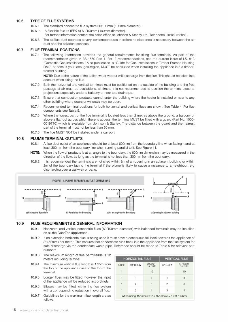
10.8 PLUME TERMINAL OUTLETS10.8.1 A flue duct outlet of an appliance should be at least 600mm from the boundary line when facing it and at
least 300mm from the boundary line when running parallel to it. See Figure 11.
NOTE: When the flow of products is at an angle to the boundary, the 600mm dimension may be measured in the direction of the flow, as long as the terminal is not less than 300mm from the boundary.
10.8.2 It is recommended the terminals are not sited within 2m of an opening in an adjacent building or within 2m of the boundary facing the terminal if the plume is likely to cause a nuisance to a neighbour, e.g discharging over a walkway or patio.
10.9 FLUE REQUIREMENTS & GENERAL INFORMATION10.9.1 Horizontal and vertical concentric flues (60/100mm diameter) with balanced terminals may be installed
on all the QuanTec appliances.
10.9.2 If an extended horizontal flue is being used it must have a continuous fall back towards the appliance of 3° (52mm) per meter. This ensures that condensate runs back into the appliance from the flue system for safe discharge via the condensate waste pipe. Reference should be made to Table 5 for relevant part numbers.
10.9.3 The maximum length of flue permissible is 12 meters including terminal
10.9.4 The minimum vertical flue length is 1.25m from the top of the appliance case to the top of the terminal.
10.9.5 Longer flues may be fitted, however the input of the appliance will be reduced accordingly.
10.9.6 Elbows may be fitted within the flue system with a corresponding reduction in overall flue.
10.9.7 Guidelines for the maximum flue length are as follows.
FIGURE 11. PLUME TERMINAL OUTLET DIMENSIONS
HORIZONTAL FLUE VERTICAL FLUE
TURRET 90° ELBOW STRAIGHT 1m FLUE 90° ELBOW STRAIGHT
1m FLUE
1 - 10 - 10
1 1 8 1 8
1 2 6 2 6
1 3 4 3 4
When using 45° elbows: 2 x 45° elbow = 1 x 90° elbow
17Sales/Spares & Replacement Help Line 01604 762881
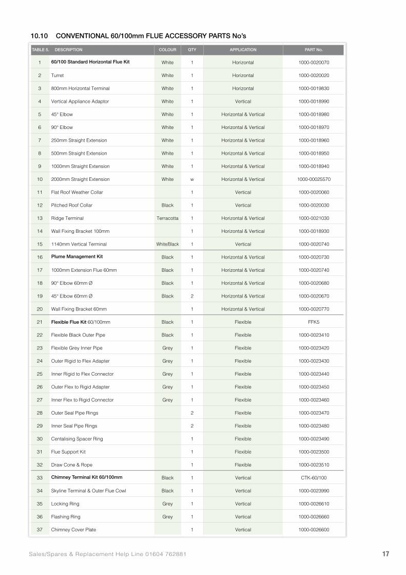
10.10 CONVENTIONAL 60/100mm FLUE ACCESSORY PARTS No’s
TABLE 5. DESCRIPTION COLOUR QTY APPLICATION PART No.
1 60/100 Standard Horizontal Flue Kit White 1 Horizontal 1000-0020070
2 Turret White 1 Horizontal 1000-0020020
3 800mm Horizontal Terminal White 1 Horizontal 1000-0019830
4 Vertical Appliance Adaptor White 1 Vertical 1000-0018990
5 45° Elbow White 1 Horizontal & Vertical 1000-0018980
6 90° Elbow White 1 Horizontal & Vertical 1000-0018970
7 250mm Straight Extension White 1 Horizontal & Vertical 1000-0018960
8 500mm Straight Extension White 1 Horizontal & Vertical 1000-0018950
9 1000mm Straight Extension White 1 Horizontal & Vertical 1000-0018940
10 2000mm Straight Extension White w Horizontal & Vertical 1000-00025570
11 Flat Roof Weather Collar 1 Vertical 1000-0020060
12 Pitched Roof Collar Black 1 Vertical 1000-0020030
13 Ridge Terminal Terracotta 1 Horizontal & Vertical 1000-0021030
14 Wall Fixing Bracket 100mm 1 Horizontal & Vertical 1000-0018930
15 1140mm Vertical Terminal White/Black 1 Vertical 1000-0020740
16 Plume Management Kit Black 1 Horizontal & Vertical 1000-0020730
17 1000mm Extension Flue 60mm Black 1 Horizontal & Vertical 1000-0020740
18 90° Elbow 60mm Ø Black 1 Horizontal & Vertical 1000-0020680
19 45° Elbow 60mm Ø Black 2 Horizontal & Vertical 1000-0020670
20 Wall Fixing Bracket 60mm 1 Horizontal & Vertical 1000-0020770
21 Flexible Flue Kit 60/100mm Black 1 Flexible FFK5
22 Flexible Black Outer Pipe Black 1 Flexible 1000-0023410
23 Flexible Grey Inner Pipe Grey 1 Flexible 1000-0023420
24 Outer Rigid to Flex Adapter Grey 1 Flexible 1000-0023430
25 Inner Rigid to Flex Connector Grey 1 Flexible 1000-0023440
26 Outer Flex to Rigid Adapter Grey 1 Flexible 1000-0023450
27 Inner Flex to Rigid Connector Grey 1 Flexible 1000-0023460
28 Outer Seal Pipe Rings 2 Flexible 1000-0023470
29 Inner Seal Pipe Rings 2 Flexible 1000-0023480
30 Centalising Spacer Ring 1 Flexible 1000-0023490
31 Flue Support Kit 1 Flexible 1000-0023500
32 Draw Cone & Rope 1 Flexible 1000-0023510
33 Chimney Terminal Kit 60/100mm Black 1 Vertical CTK-60/100
34 Skyline Terminal & Outer Flue Cowl Black 1 Vertical 1000-0023990
35 Locking Ring Grey 1 Vertical 1000-0026610
36 Flashing Ring Grey 1 Vertical 1000-0026660
37 Chimney Cover Plate 1 Vertical 1000-0026600
www.johnsonandstarley.co.uk18
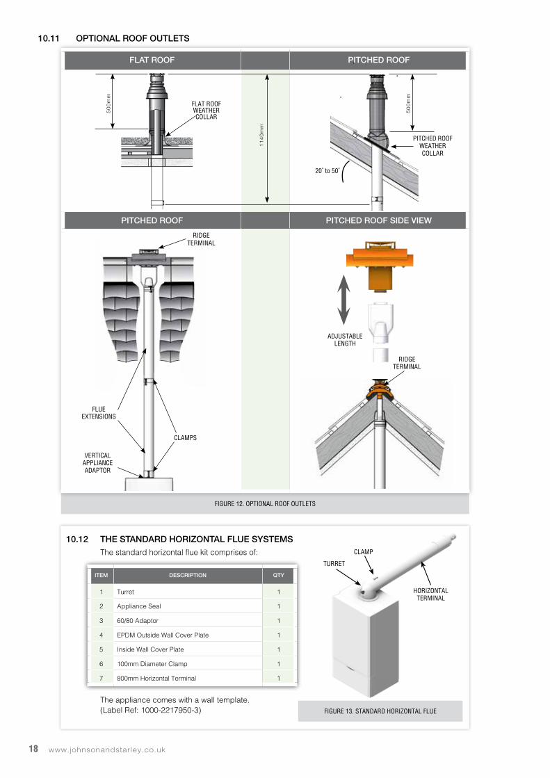
FIGURE 12. OPTIONAL ROOF OUTLETS
HORIZONTAL TERMINAL
TURRET
CLAMP
FIGURE 13. STANDARD HORIZONTAL FLUE
10.12 THE STANDARD HORIZONTAL FLUE SYSTEMSThe standard horizontal flue kit comprises of:
The appliance comes with a wall template. (Label Ref: 1000-2217950-3)
ITEM DESCRIPTION QTY
1 Turret 1
2 Appliance Seal 1
3 60/80 Adaptor 1
4 EPDM Outside Wall Cover Plate 1
5 Inside Wall Cover Plate 1
6 100mm Diameter Clamp 1
7 800mm Horizontal Terminal 1
10.11 OPTIONAL ROOF OUTLETS
FLAT ROOF PITCHED ROOF
PITCHED ROOF PITCHED ROOF SIDE VIEW
50
0m
m
PITCHED ROOF WEATHER COLLAR
50
0m
m
11
40
mm
FLAT ROOF WEATHER COLLAR
20˚ to 50˚
RIDGE TERMINAL
CLAMPS
FLUE EXTENSIONS
VERTICAL APPLIANCE ADAPTOR
ADJUSTABLELENGTH
RIDGE TERMINAL
19Sales/Spares & Replacement Help Line 01604 762881
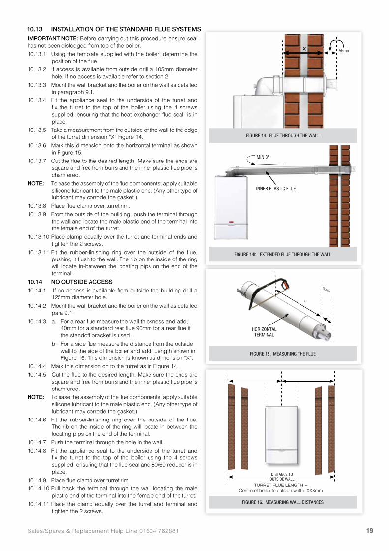
IMPORTANT NOTE: Before carrying out this procedure ensure seal has not been dislodged from top of the boiler.
10.13.1 Using the template supplied with the boiler, determine the position of the flue.
10.13.2 If access is available from outside drill a 105mm diameter hole. If no access is available refer to section 2.
10.13.3 Mount the wall bracket and the boiler on the wall as detailed in paragraph 9.1.
10.13.4 Fit the appliance seal to the underside of the turret and fix the turret to the top of the boiler using the 4 screws supplied, ensuring that the heat exchanger flue seal is in place.
10.13.5 Take a measurement from the outside of the wall to the edge of the turret dimension “X” Figure 14.
10.13.6 Mark this dimension onto the horizontal terminal as shown in Figure 15.
10.13.7 Cut the flue to the desired length. Make sure the ends are square and free from burrs and the inner plastic flue pipe is chamfered.
NOTE: To ease the assembly of the flue components, apply suitable silicone lubricant to the male plastic end. (Any other type of lubricant may corrode the gasket.)
10.13.8 Place flue clamp over turret rim.
10.13.9 From the outside of the building, push the terminal through the wall and locate the male plastic end of the terminal into the female end of the turret.
10.13.10 Place clamp equally over the turret and terminal ends and tighten the 2 screws.
10.13.11 Fit the rubber-finishing ring over the outside of the flue, pushing it flush to the wall. The rib on the inside of the ring will locate in-between the locating pips on the end of the terminal.
10.14 NO OUTSIDE ACCESS10.14.1 If no access is available from outside the building drill a
125mm diameter hole.
10.14.2 Mount the wall bracket and the boiler on the wall as detailed para 9.1.
10.14.3. a. For a rear flue measure the wall thickness and add; 40mm for a standard rear flue 90mm for a rear flue if the standoff bracket is used.
b. For a side flue measure the distance from the outside wall to the side of the boiler and add; Length shown in Figure 16. This dimension is known as dimension “X”.
10.14.4 Mark this dimension on to the turret as in Figure 14.
10.14.5 Cut the flue to the desired length. Make sure the ends are square and free from burrs and the inner plastic flue pipe is chamfered.
NOTE: To ease the assembly of the flue components, apply suitable silicone lubricant to the male plastic end. (Any other type of lubricant may corrode the gasket.)
10.14.6 Fit the rubber-finishing ring over the outside of the flue. The rib on the inside of the ring will locate in-between the locating pips on the end of the terminal.
10.14.7 Push the terminal through the hole in the wall.
10.14.8 Fit the appliance seal to the underside of the turret and fix the turret to the top of the boiler using the 4 screws supplied, ensuring that the flue seal and 80/60 reducer is in place.
10.14.9 Place flue clamp over turret rim.
10.14.10 Pull back the terminal through the wall locating the male plastic end of the terminal into the female end of the turret.
10.14.11 Place the clamp equally over the turret and terminal and tighten the 2 screws.
10.13 INSTALLATION OF THE STANDARD FLUE SYSTEMS
X 55mm
55mm
x
FIGURE 15. MEASURING THE FLUE
FIGURE 14b. EXTENDED FLUE THROUGH THE WALL
FIGURE 14. FLUE THROUGH THE WALL
DISTANCE TO OUTSIDE WALL
TURRET FLUE LENGTH = Centre of boiler to outside wall + XXXmm
FIGURE 16. MEASURING WALL DISTANCES
INNER PLASTIC FLUE
MIN 3°
HORIZONTAL TERMINAL
www.johnsonandstarley.co.uk20
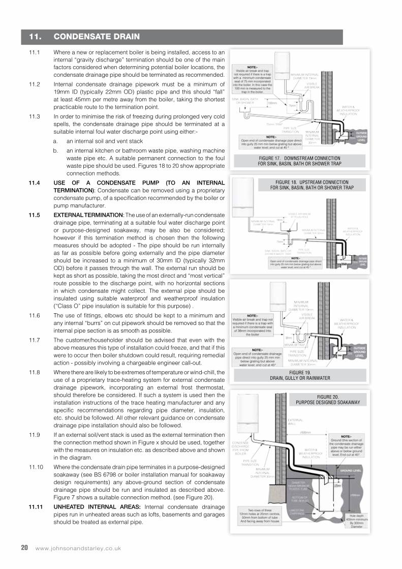
11. CONDENSATE DRAIN
11.1 Where a new or replacement boiler is being installed, access to an internal “gravity discharge” termination should be one of the main factors considered when determining potential boiler locations, the condensate drainage pipe should be terminated as recommended.
11.2 Internal condensate drainage pipework must be a minimum of 19mm ID (typically 22mm OD) plastic pipe and this should “fall” at least 45mm per metre away from the boiler, taking the shortest practicable route to the termination point.
11.3 In order to minimise the risk of freezing during prolonged very cold spells, the condensate drainage pipe should be terminated at a suitable internal foul water discharge point using either:-
a. an internal soil and vent stack
b. an internal kitchen or bathroom waste pipe, washing machine waste pipe etc. A suitable permanent connection to the foul waste pipe should be used. Figures 18 to 20 show appropriate connection methods.
11.4 USE OF A CONDENSATE PUMP (TO AN INTERNAL TERMINATION): Condensate can be removed using a proprietary condensate pump, of a specification recommended by the boiler or pump manufacturer.
11.5 EXTERNAL TERMINATION: The use of an externally-run condensate drainage pipe, terminating at a suitable foul water discharge point or purpose-designed soakaway, may be also be considered; however if this termination method is chosen then the following measures should be adopted - The pipe should be run internally as far as possible before going externally and the pipe diameter should be increased to a minimum of 30mm ID (typically 32mm OD) before it passes through the wall. The external run should be kept as short as possible, taking the most direct and “most vertical” route possible to the discharge point, with no horizontal sections in which condensate might collect. The external pipe should be insulated using suitable waterproof and weatherproof insulation (“Class O” pipe insulation is suitable for this purpose) .
11.6 The use of fittings, elbows etc should be kept to a minimum and any internal “burrs” on cut pipework should be removed so that the internal pipe section is as smooth as possible.
11.7 The customer/householder should be advised that even with the above measures this type of installation could freeze, and that if this were to occur then boiler shutdown could result, requiring remedial action - possibly involving a chargeable engineer call-out.
11.8 Where there are likely to be extremes of temperature or wind-chill, the use of a proprietary trace-heating system for external condensate drainage pipework, incorporating an external frost thermostat, should therefore be considered. If such a system is used then the installation instructions of the trace heating manufacturer and any specific recommendations regarding pipe diameter, insulation, etc. should be followed. All other relevant guidance on condensate drainage pipe installation should also be followed.
11.9 If an external soil/vent stack is used as the external termination then the connection method shown in Figure x should be used, together with the measures on insulation etc. as described above and shown in the diagram.
11.10 Where the condensate drain pipe terminates in a purpose-designed soakaway (see BS 6798 or boiler installation manual for soakaway design requirements) any above-ground section of condensate drainage pipe should be run and insulated as described above. Figure 7 shows a suitable connection method. (see Figure 20).
11.11 UNHEATED INTERNAL AREAS: Internal condensate drainage pipes run in unheated areas such as lofts, basements and garages should be treated as external pipe.
FIGURE 17. DOWNSTREAM CONNECTIONFOR SINK, BASIN, BATH OR SHOWER TRAP
FIGURE 18. UPSTREAM CONNECTIONFOR SINK, BASIN, BATH OR SHOWER TRAP
FIGURE 19.DRAIN, GULLY OR RAINWATER
FIGURE 20.PURPOSE DESIGNED SOAKAWAY
21Sales/Spares & Replacement Help Line 01604 762881
12. ELECTRICAL
WARNING: This appliance must be earthed.
12.1 DROP DOWN CONTROL PANEL: See paragraph 17.5.
12.2 ELECTRICAL CONNECTIONS12.2.1 A mains supply of 230Vac ~ 50 Hz is required.
12.2.2 The fuse rating should be 3A. All external controls and wiring must be suitable for mains voltage.
12.2.3 Wiring external to the boiler MUST be in accordance with the current I.E.E. (BS 7671) Wiring Regulations and any local regulations.
12.2.4 Wiring should be 3 core PVC insulated cable, not less than 0.75mm2 (24 x 0.2mm), and to BS 6500. For IE reference should be made to the current ETCI rules for electrical installations.
12.2.5 Connection must be made in a way that allows complete isolation of the electrical supply such as a double pole switch having a 3mm (1/8”) contact separation in both poles. The means of isolation must be accessible to the user after installation.
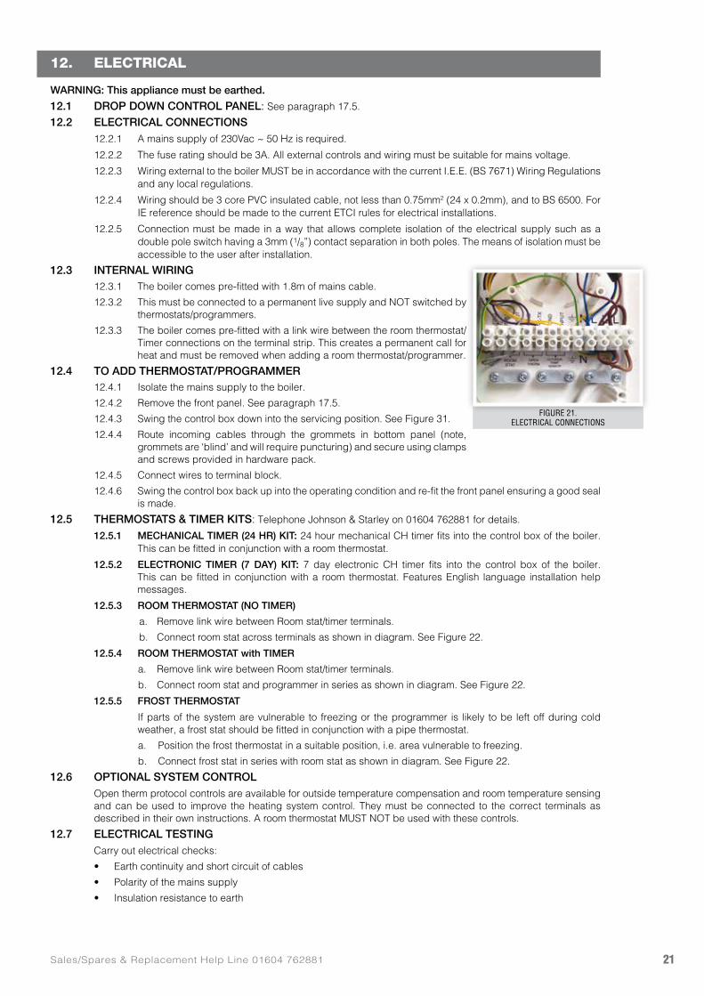
12.3 INTERNAL WIRING12.3.1 The boiler comes pre-fitted with 1.8m of mains cable.
12.3.2 This must be connected to a permanent live supply and NOT switched by thermostats/programmers.
12.3.3 The boiler comes pre-fitted with a link wire between the room thermostat/Timer connections on the terminal strip. This creates a permanent call for heat and must be removed when adding a room thermostat/programmer.
12.4 TO ADD THERMOSTAT/PROGRAMMER12.4.1 Isolate the mains supply to the boiler.
12.4.2 Remove the front panel. See paragraph 17.5.
12.4.3 Swing the control box down into the servicing position. See Figure 31.
12.4.4 Route incoming cables through the grommets in bottom panel (note, grommets are ‘blind’ and will require puncturing) and secure using clamps and screws provided in hardware pack.
12.4.5 Connect wires to terminal block.
12.4.6 Swing the control box back up into the operating condition and re-fit the front panel ensuring a good seal is made.
12.5 THERMOSTATS & TIMER KITS: Telephone Johnson & Starley on 01604 762881 for details.
12.5.1 MECHANICAL TIMER (24 HR) KIT: 24 hour mechanical CH timer fits into the control box of the boiler. This can be fitted in conjunction with a room thermostat.
12.5.2 ELECTRONIC TIMER (7 DAY) KIT: 7 day electronic CH timer fits into the control box of the boiler. This can be fitted in conjunction with a room thermostat. Features English language installation help messages.
12.5.3 ROOM THERMOSTAT (NO TIMER)
a. Remove link wire between Room stat/timer terminals.
b. Connect room stat across terminals as shown in diagram. See Figure 22.
12.5.4 ROOM THERMOSTAT with TIMER
a. Remove link wire between Room stat/timer terminals.
b. Connect room stat and programmer in series as shown in diagram. See Figure 22.
12.5.5 FROST THERMOSTAT
If parts of the system are vulnerable to freezing or the programmer is likely to be left off during cold weather, a frost stat should be fitted in conjunction with a pipe thermostat.
a. Position the frost thermostat in a suitable position, i.e. area vulnerable to freezing.
b. Connect frost stat in series with room stat as shown in diagram. See Figure 22.
12.6 OPTIONAL SYSTEM CONTROL Open therm protocol controls are available for outside temperature compensation and room temperature sensing
and can be used to improve the heating system control. They must be connected to the correct terminals as described in their own instructions. A room thermostat MUST NOT be used with these controls.
12.7 ELECTRICAL TESTING Carry out electrical checks:
• Earth continuity and short circuit of cables
• Polarity of the mains supply
• Insulation resistance to earth
FIGURE 21.ELECTRICAL CONNECTIONS
www.johnsonandstarley.co.uk22
13. WIRING DIAGRAM
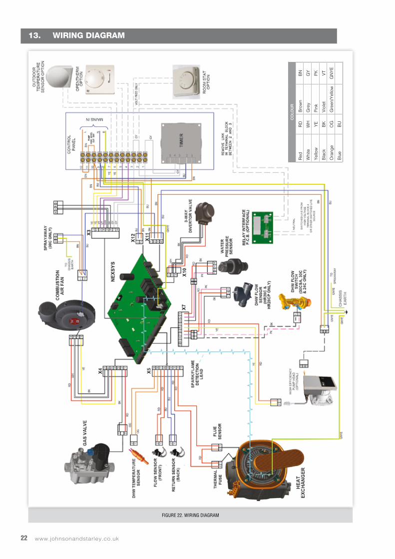
FIGURE 22. WIRING DIAGRAM
CO
LOU
R
Red
RD
Bro
wn
BN
Whi
teW
HG
rey
GY
Yel
low
YE
Pin
kP
K
Bla
ckB
KV
iole
tV
T
Ora
nge
OG
Gre
en/Y
ello
wG
NY
E
Blu
eB
U
23Sales/Spares & Replacement Help Line 01604 762881
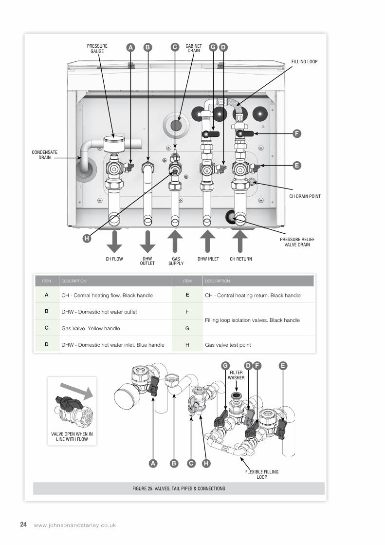
14. CONNECTIONS & FILLINGNOTES. Ensure all boss blanking plugs are removed before connecting hardware. Each valve must be fitted to the correct
boss as shown. See Figure 25. Ensure each union is fitted with fibre seals provided. On the DHW inlet use the filter washer provided. DO NOT use
a fibre seal. Do not subject any of the isolating valves to heat as the seals may be damaged.14.1 WATER CONNECTIONS CH
14.1.1 Connect the CH flow service valve (black handle) and copper tail provided in the hardware pack to the threaded boss connection provided at the lower rear of the boiler.
14.1.2 Connect the CH return valve (black handle) and copper tail.14.2 GAS CONNECTION
IMPORTANT. The gas service cock is sealed with a non-metallic blue fibre washer, which must not be overheated when making capillary connections. See Figure 23 for details of the position of the gas connection.14.2.1 For additional information of the Gas Supply see paragraph 4.3.
14.3 CONDENSATE DRAIN14.3.1 The condensate drain tube is secured by a cable tie when packed. This cable tie needs to be cut and
removed before connecting to the condensate drain hose. Remove the bung from the pipe.14.3.2 Connect the condensate drain tube.
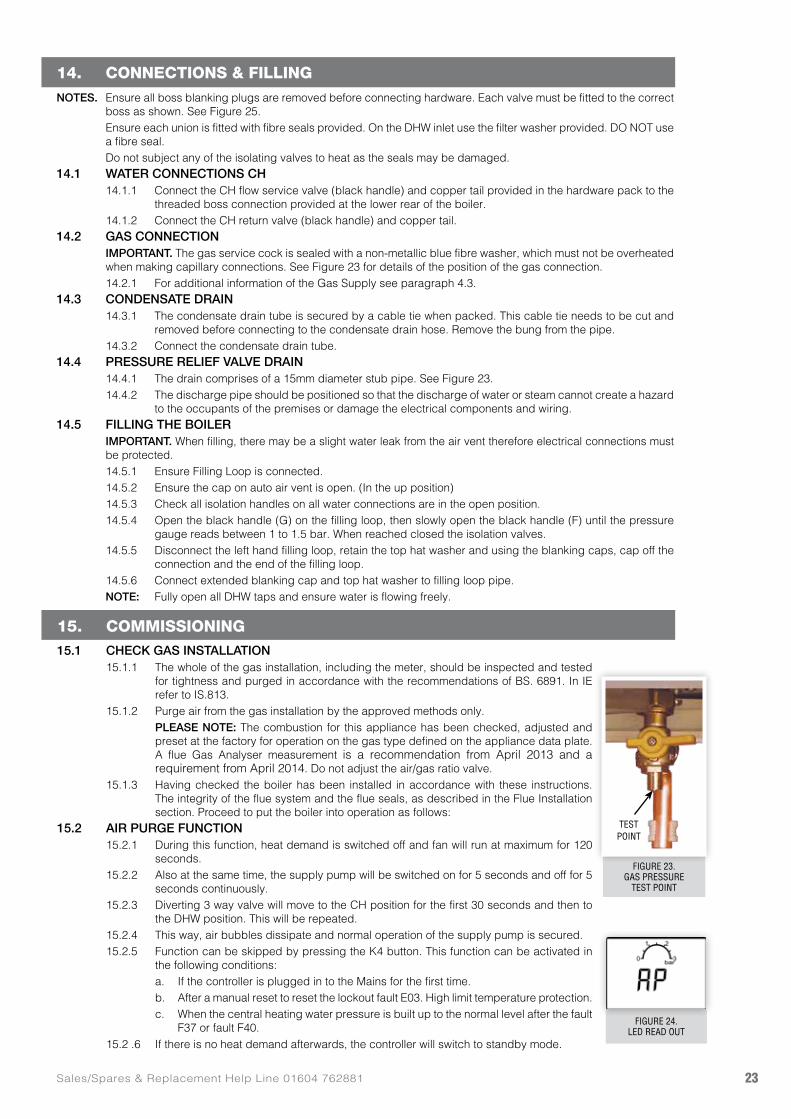
14.4 PRESSURE RELIEF VALVE DRAIN14.4.1 The drain comprises of a 15mm diameter stub pipe. See Figure 23. 14.4.2 The discharge pipe should be positioned so that the discharge of water or steam cannot create a hazard
to the occupants of the premises or damage the electrical components and wiring.14.5 FILLING THE BOILER
IMPORTANT. When filling, there may be a slight water leak from the air vent therefore electrical connections must be protected.14.5.1 Ensure Filling Loop is connected.14.5.2 Ensure the cap on auto air vent is open. (In the up position)14.5.3 Check all isolation handles on all water connections are in the open position.14.5.4 Open the black handle (G) on the filling loop, then slowly open the black handle (F) until the pressure
gauge reads between 1 to 1.5 bar. When reached closed the isolation valves.14.5.5 Disconnect the left hand filling loop, retain the top hat washer and using the blanking caps, cap off the
connection and the end of the filling loop.14.5.6 Connect extended blanking cap and top hat washer to filling loop pipe.NOTE: Fully open all DHW taps and ensure water is flowing freely.
15. COMMISSIONING15.1 CHECK GAS INSTALLATION
15.1.1 The whole of the gas installation, including the meter, should be inspected and tested for tightness and purged in accordance with the recommendations of BS. 6891. In IE refer to IS.813.
15.1.2 Purge air from the gas installation by the approved methods only. PLEASE NOTE: The combustion for this appliance has been checked, adjusted and
preset at the factory for operation on the gas type defined on the appliance data plate. A flue Gas Analyser measurement is a recommendation from April 2013 and a requirement from April 2014. Do not adjust the air/gas ratio valve.
15.1.3 Having checked the boiler has been installed in accordance with these instructions. The integrity of the flue system and the flue seals, as described in the Flue Installation section. Proceed to put the boiler into operation as follows:
15.2 AIR PURGE FUNCTION15.2.1 During this function, heat demand is switched off and fan will run at maximum for 120
seconds.15.2.2 Also at the same time, the supply pump will be switched on for 5 seconds and off for 5
seconds continuously.15.2.3 Diverting 3 way valve will move to the CH position for the first 30 seconds and then to
the DHW position. This will be repeated.15.2.4 This way, air bubbles dissipate and normal operation of the supply pump is secured.15.2.5 Function can be skipped by pressing the K4 button. This function can be activated in
the following conditions:a. If the controller is plugged in to the Mains for the first time.b. After a manual reset to reset the lockout fault E03. High limit temperature protection.c. When the central heating water pressure is built up to the normal level after the fault
F37 or fault F40. 15.2 .6 If there is no heat demand afterwards, the controller will switch to standby mode.
FIGURE 23.GAS PRESSURE
TEST POINT
FIGURE 24.LED READ OUT
TESTPOINT
www.johnsonandstarley.co.uk24
A B C
E
D
F
G
CH FLOW
CONDENSATEDRAIN
VALVE OPEN WHEN IN LINE WITH FLOW
PRESSUREGAUGE
FILLING LOOP
CABINET DRAIN
DHWOUTLET
GASSUPPLY
PRESSURE RELIEFVALVE DRAIN
DHW INLET CH RETURN
CH DRAIN POINT
ITEM DESCRIPTION ITEM DESCRIPTION
A CH - Central heating flow. Black handle E CH - Central heating return. Black handle
B DHW - Domestic hot water outlet F
Filling loop isolation valves. Black handleC Gas Valve. Yellow handle G
D DHW - Domestic hot water inlet. Blue handle H Gas valve test point
H
ED FG
A B C H
FILTERWASHER
FIGURE 25. VALVES, TAIL PIPES & CONNECTIONS
FLEXIBLE FILLING LOOP
25Sales/Spares & Replacement Help Line 01604 762881
15.5 INITIAL LIGHTING15.5.1 Check that the system has been filled and the boiler is not air-locked. Ensure the automatic air vent cap
is open.
NOTE: It is important the burner is not operated before the system is fully vented of air.
IMPORTANT: The gas input to the burner is regulated by the gas valve according to the air flow produced by the fan. It is not user-adjustable. Any interference to sealed settings on the gas valve will adversely affect operation and render our warranty void.
15.5.2 Refit the boiler front panel. See paragraph 17.5.
15.5.3 Check that the drain cock is closed and that the CH and DHW isolating valves (A, E, and D) are OPEN.
15.5.4 Check that the electrical supply is OFF.
15.5.5 Check that the gas service cock is OPEN. (C)
15.5.6 Slacken the screw in the inlet pressure test point (H) and connect a gas pressure gauge via a flexible tube.
15.5.7 Switch the electricity supply ON and check all external controls are OFF. The boiler will select ‘self purge’
15.6 CENTRAL HEATING 15.6.1 Select the winter mode.
15.6.2 Set the CH temperature to maximum and switch on thermostat. The boiler control should now go through its ignition sequence until the burner is established.
15.6.3 If the boiler does not light, after 5 attempts the error code E-01 will be displayed.
15.6.4 Reset the boiler (see paragraph 15.3). The boiler will repeat its ignition sequence. If reset occurs 5 times within 15 minutes then F-15 will be shown. If power is removed this will be reset.
15.6.5 When the burner is established the display will show the ‘flame symbol’.
15.7 DOMESTIC HOT WATER15.7.1 With the boiler firing, set the DHW Temperature Control to maximum and fully open a DHW tap. The
boiler should continue to run and the display should show the ‘flame symbol’.
15.7.2 Ensure that with the boiler operating the dynamic gas pressure is able to obtain maximum output.
15.7.3 Turn off the DHW tap.
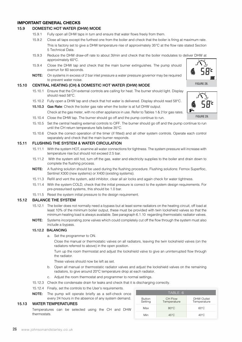
15.8 CHECK THE OPERATIONAL GAS INLET PRESSURE15.8.1 Set up the boiler to operate at maximum rate by opening hot tap to maximum flow.
15.8.2 With the boiler operating in the maximum rate condition check the operational gas pressure at the inlet gas pressure test point complies with the requirements.
15.8.3 Ensure that this inlet pressure can be obtained with all other gas appliances in the property working.
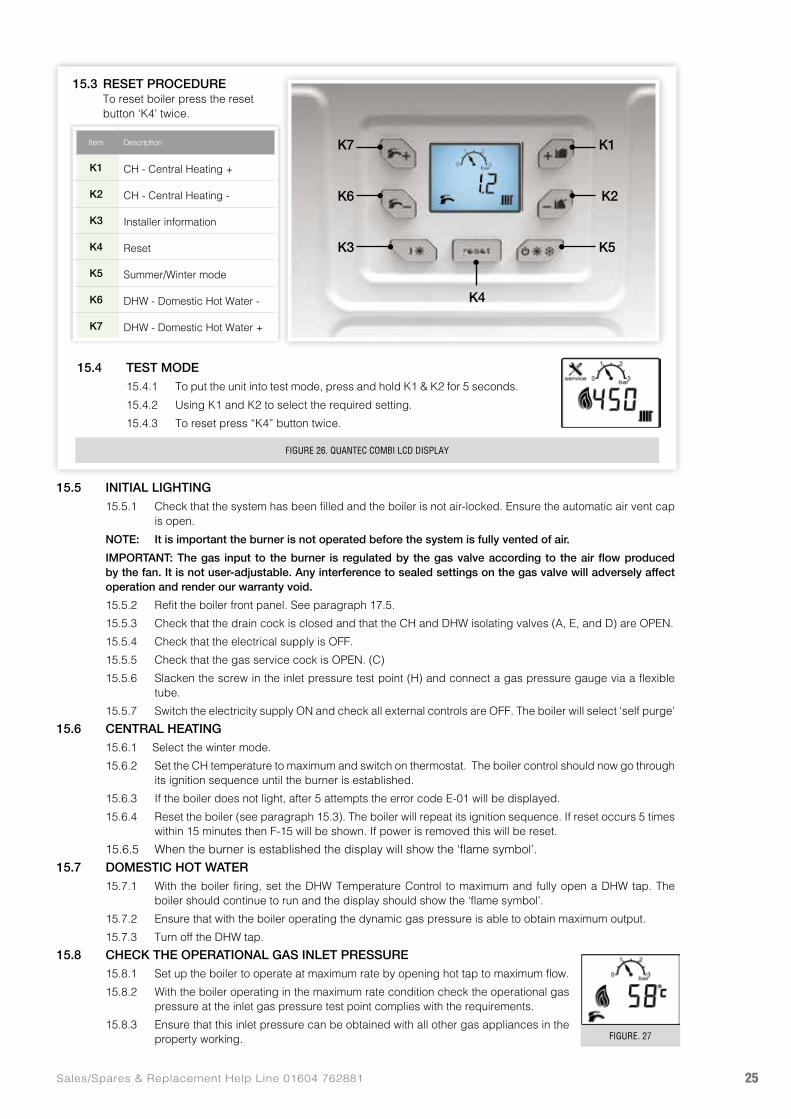
FIGURE 26. QUANTEC COMBI LCD DISPLAY
FIGURE. 27
K7 K1
K6 K2
K3 K5
K4
Item Description
K1 CH - Central Heating +
K2 CH - Central Heating -
K3 Installer information
K4 Reset
K5 Summer/Winter mode
K6 DHW - Domestic Hot Water -
K7 DHW - Domestic Hot Water +
15.3 RESET PROCEDURE To reset boiler press the reset
button ‘K4’ twice.
15.4 TEST MODE15.4.1 To put the unit into test mode, press and hold K1 & K2 for 5 seconds.
15.4.2 Using K1 and K2 to select the required setting.
15.4.3 To reset press “K4” button twice.
www.johnsonandstarley.co.uk26
IMPORTANT GENERAL CHECKS 15.9 DOMESTIC HOT WATER (DHW) MODE
15.9.1 Fully open all DHW taps in turn and ensure that water flows freely from them.
15.9.2 Close all taps except the furthest one from the boiler and check that the boiler is firing at maximum rate.
This is factory set to give a DHW temperature rise of approximately 35°C at the flow rate stated Section 5 Technical Data.
15.9.3 Reduce the DHW draw-off rate to about 3l/min and check that the boiler modulates to deliver DHW at approximately 60°C.
15.9.4 Close the DHW tap and check that the main burner extinguishes. The pump should overrun for 60 seconds.
NOTE: On systems in excess of 2 bar inlet pressure a water pressure governor may be required to prevent water noise.
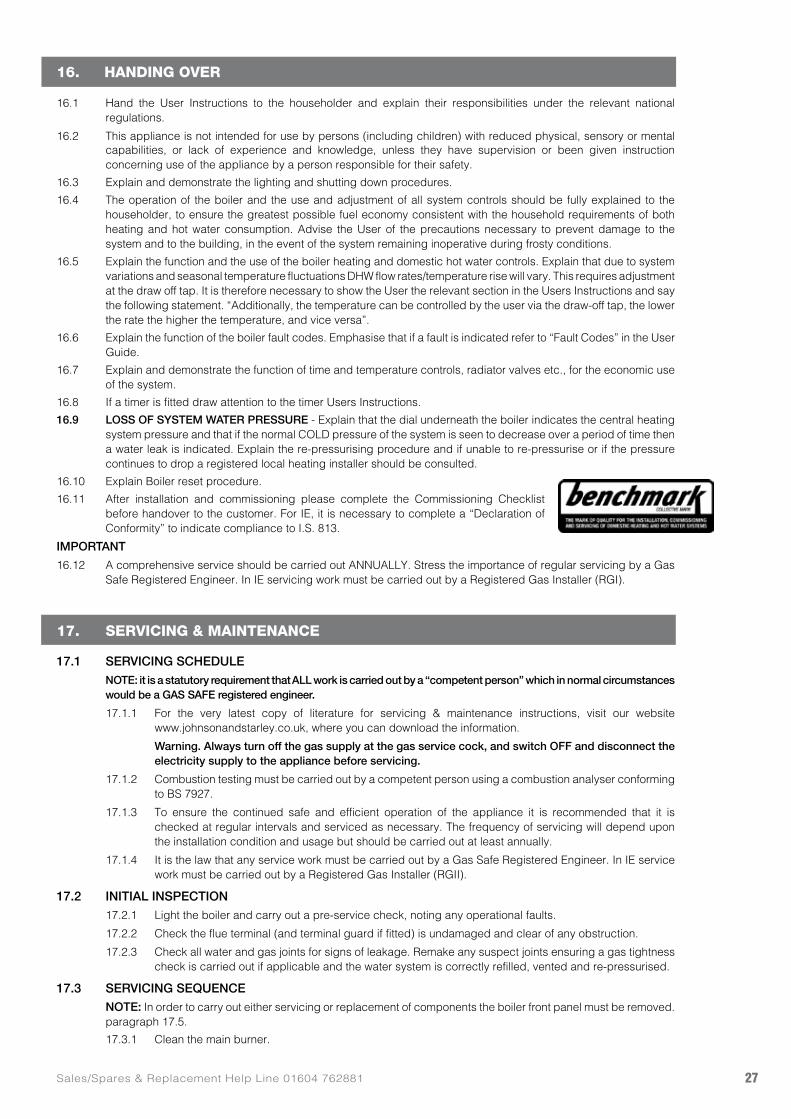
15.10 CENTRAL HEATING (CH) & DOMESTIC HOT WATER (DHW) MODE15.10.1 Ensure that the CH external controls are calling for heat. The burner should light. Display
should read 58°C.
15.10.2 Fully open a DHW tap and check that hot water is delivered. Display should read 58°C.
15.10.3 Gas Rate: Check the boiler gas rate when the boiler is at full DHW output.
Check at the gas meter, with no other appliance in use. Refer to Tables 1 & 2 for gas rates.
15.10.4 Close the DHW tap. The burner should go off and the pump continue to run.
15.10.5 Set the central heating external controls to OFF. The burner should go off and the pump continue to run until the CH return temperature falls below 35°C.
15.10.6 Check the correct operation of the timer (if fitted) and all other system controls. Operate each control separately and check that the main burner responds.
15.11 FLUSHING THE SYSTEM & WATER CIRCULATION15.11.1 With the system HOT, examine all water connections for tightness. The system pressure will increase with
temperature rise but should not exceed 2.5 bar.
15.11.2 With the system still hot, turn off the gas, water and electricity supplies to the boiler and drain down to complete the flushing process.
NOTE: A flushing solution should be used during the flushing procedure. Flushing solutions: Fernox Superfloc, Sentinel X300 (new systems) or X400 (existing systems).
15.11.3 Refill and vent the system, add inhibitor, clear all air locks and again check for water tightness.
15.11.4 With the system COLD, check that the initial pressure is correct to the system design requirements. For pre-pressurised systems, this should be 1.0 bar.
15.11.5 Reset the system initial pressure to the design requirement.
15.12 BALANCE THE SYSTEM15.12.1 The boiler does not normally need a bypass but at least some radiators on the heating circuit, off load at
least 10% of the minimum boiler output, these must be provided with twin lockshield valves so that the minimum heating load is always available. See paragraph 6.1.10 regarding thermostatic radiator valves.
NOTE: Systems incorporating zone valves which could completely cut off the flow through the system must also include a bypass.
15.12.2 BALANCING
a. Set the programmer to ON.
Close the manual or thermostatic valves on all radiators, leaving the twin lockshield valves (on the radiators referred to above) in the open position.
Turn up the room thermostat and adjust the lockshield valve to give an uninterrupted flow through the radiator.
These valves should now be left as set.
b. Open all manual or thermostatic radiator valves and adjust the lockshield valves on the remaining radiators, to give around 20°C temperature drop at each radiator.
c. Adjust the room thermostat and programmer to normal settings.
15.12.3 Check the condensate drain for leaks and check that it is discharging correctly.
15.12.4 Finally, set the controls to the User’s requirements.
NOTE: The pump will operate briefly as a self-check once every 24 hours in the absence of any system demand.
15.13 WATER TEMPERATURES Temperatures can be selected using the CH and DHW
thermostats.
FIGURE 29.
FIGURE 28.
TABLE. 6
ButtonSetting
CH FlowTemperature
DHW Outlet Temperature
Max 80°C 60°C
Min 45°C 40°C
27Sales/Spares & Replacement Help Line 01604 762881
16. HANDING OVER
16.1 Hand the User Instructions to the householder and explain their responsibilities under the relevant national regulations.
16.2 This appliance is not intended for use by persons (including children) with reduced physical, sensory or mental capabilities, or lack of experience and knowledge, unless they have supervision or been given instruction concerning use of the appliance by a person responsible for their safety.
16.3 Explain and demonstrate the lighting and shutting down procedures.
16.4 The operation of the boiler and the use and adjustment of all system controls should be fully explained to the householder, to ensure the greatest possible fuel economy consistent with the household requirements of both heating and hot water consumption. Advise the User of the precautions necessary to prevent damage to the system and to the building, in the event of the system remaining inoperative during frosty conditions.
16.5 Explain the function and the use of the boiler heating and domestic hot water controls. Explain that due to system variations and seasonal temperature fluctuations DHW flow rates/temperature rise will vary. This requires adjustment at the draw off tap. It is therefore necessary to show the User the relevant section in the Users Instructions and say the following statement. “Additionally, the temperature can be controlled by the user via the draw-off tap, the lower the rate the higher the temperature, and vice versa”.
16.6 Explain the function of the boiler fault codes. Emphasise that if a fault is indicated refer to “Fault Codes” in the User Guide.
16.7 Explain and demonstrate the function of time and temperature controls, radiator valves etc., for the economic use of the system.
16.8 If a timer is fitted draw attention to the timer Users Instructions.
16.9 LOSS OF SYSTEM WATER PRESSURE - Explain that the dial underneath the boiler indicates the central heating system pressure and that if the normal COLD pressure of the system is seen to decrease over a period of time then a water leak is indicated. Explain the re-pressurising procedure and if unable to re-pressurise or if the pressure continues to drop a registered local heating installer should be consulted.
16.10 Explain Boiler reset procedure.
16.11 After installation and commissioning please complete the Commissioning Checklist before handover to the customer. For IE, it is necessary to complete a “Declaration of Conformity” to indicate compliance to I.S. 813.
IMPORTANT
16.12 A comprehensive service should be carried out ANNUALLY. Stress the importance of regular servicing by a Gas Safe Registered Engineer. In IE servicing work must be carried out by a Registered Gas Installer (RGI).
17. SERVICING & MAINTENANCE
17.1 SERVICING SCHEDULE NOTE: it is a statutory requirement that ALL work is carried out by a “competent person” which in normal circumstances
would be a GAS SAFE registered engineer.
17.1.1 For the very latest copy of literature for servicing & maintenance instructions, visit our website www.johnsonandstarley.co.uk, where you can download the information.
Warning. Always turn off the gas supply at the gas service cock, and switch OFF and disconnect the electricity supply to the appliance before servicing.
17.1.2 Combustion testing must be carried out by a competent person using a combustion analyser conforming to BS 7927.
17.1.3 To ensure the continued safe and efficient operation of the appliance it is recommended that it is checked at regular intervals and serviced as necessary. The frequency of servicing will depend upon the installation condition and usage but should be carried out at least annually.
17.1.4 It is the law that any service work must be carried out by a Gas Safe Registered Engineer. In IE service work must be carried out by a Registered Gas Installer (RGII).
17.2 INITIAL INSPECTION17.2.1 Light the boiler and carry out a pre-service check, noting any operational faults.
17.2.2 Check the flue terminal (and terminal guard if fitted) is undamaged and clear of any obstruction.
17.2.3 Check all water and gas joints for signs of leakage. Remake any suspect joints ensuring a gas tightness check is carried out if applicable and the water system is correctly refilled, vented and re-pressurised.
17.3 SERVICING SEQUENCE NOTE: In order to carry out either servicing or replacement of components the boiler front panel must be removed.
paragraph 17.5.
17.3.1 Clean the main burner.
www.johnsonandstarley.co.uk28
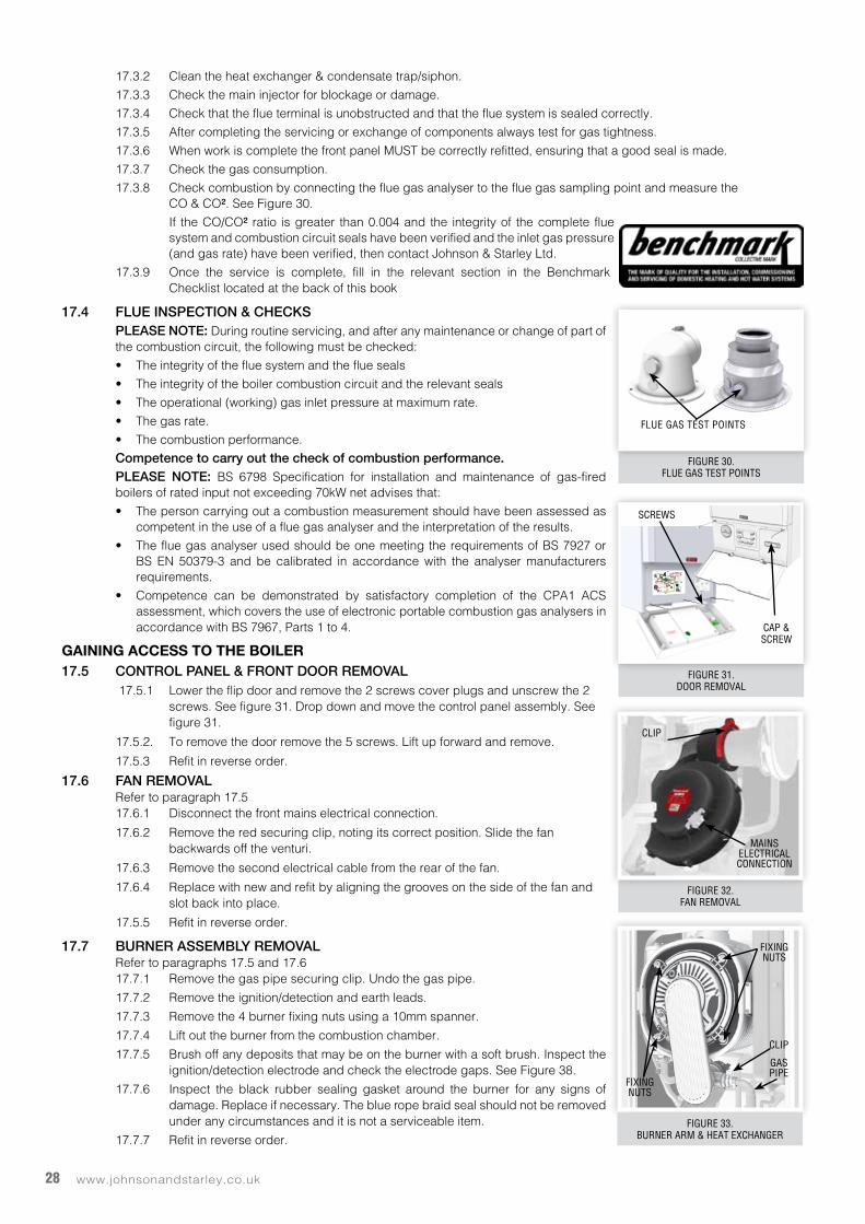
FIGURE 31. DOOR REMOVAL
FIGURE 30.FLUE GAS TEST POINTS
FLUE GAS TEST POINTS
FIGURE 32. FAN REMOVAL
CLIP
MAINS ELECTRICAL CONNECTION
FIGURE 33.BURNER ARM & HEAT EXCHANGER
FIXING NUTS
FIXING NUTS
GAS PIPE
CLIP
SCREWS
CAP & SCREW
OUTDOORTEMPERATURE
SENSOR OPTION
X4765432
4321
12
BK
RD
RD
YE
BK
X4765432
4321
1
1
2
WH
2 12 1
X5987654321
21
21
FLOW SENSOR(FRONT)
THERMALFUSE
FLUESENSOR
RD
RD
RETURN SENSOR(BACK)
RD
RDRD
BUBU
DHW TEMPERATURE SENSOR
21
OG
OG
GAS VALVE
COMBUSTIONAIR FAN
NEXSYS
HEATEXCHANGER
23
X10
1
3-WAYDIVERTOR VALVERD
BK
WH
123
DHW FLOWSENSOR(HR28C &
HR28CP ONLY)
DHW FLOWSWITCH
(30CSA, 30C & 24C ONLY)
6 5 4 3 2 1 X710 9 8 7
21 3
21
21 3 4
34
56
78
12
X3
1
432
RD
BK
BK
RDPK
PKRD
YE
PK BK
RD
WATERPRESSURE
SENSOR
X12
12
X11
21
1
2
3
4
5
6
7
89
10
CONTROLPANEL
BN
BU
BN
BN
BU
BU
YE
GY
VT
BN
BU
YE
YE
GY
GY
GY
GNYE
CHASSISEARTH
GNYEGNYE
BN
BU
BN
BU
GY
OPENTHERMOPTION
ROOM STATOPTION
TIMER
MA
INS
IN
SPARK/FLAMEDETECTION
LEAD
GNYE
QUANTEC WIRING DIAGRAMHR & COMBI MODELS
GNYE
L
N
E
BN
BU
WARNING!DISCONNECT MAINS BEFORE
REMOVING THIS COVER.
NEUTRAL
SWITCHED LIVE FROM HIGH VOLTAGE
TERMINAL BLOCK 4OR OTHER SWITCHED LIVE
SOURCE
RELAY INTERFACEP.C.B. (OPTIONAL)
BNBN 11
12
VTYE
VOLT FREE ONLY
PUMP HEADHIGH EFFICIENCY
23
1
2 1
YE
23
1
(OPTIONAL)
2 1342 13
WHBK
TOCHASSISEARTH
TOSPRAYAWAYY
SPRAYAWAY
17.3.2 Clean the heat exchanger & condensate trap/siphon.
17.3.3 Check the main injector for blockage or damage.
17.3.4 Check that the flue terminal is unobstructed and that the flue system is sealed correctly.
17.3.5 After completing the servicing or exchange of components always test for gas tightness.
17.3.6 When work is complete the front panel MUST be correctly refitted, ensuring that a good seal is made.
17.3.7 Check the gas consumption.
17.3.8 Check combustion by connecting the flue gas analyser to the flue gas sampling point and measure the CO & CO². See Figure 30.
If the CO/CO² ratio is greater than 0.004 and the integrity of the complete flue system and combustion circuit seals have been verified and the inlet gas pressure (and gas rate) have been verified, then contact Johnson & Starley Ltd.
17.3.9 Once the service is complete, fill in the relevant section in the Benchmark Checklist located at the back of this book
17.4 FLUE INSPECTION & CHECKS PLEASE NOTE: During routine servicing, and after any maintenance or change of part of
the combustion circuit, the following must be checked:
• The integrity of the flue system and the flue seals
• The integrity of the boiler combustion circuit and the relevant seals
• The operational (working) gas inlet pressure at maximum rate.
• The gas rate.
• The combustion performance.
Competence to carry out the check of combustion performance. PLEASE NOTE: BS 6798 Specification for installation and maintenance of gas-fired
boilers of rated input not exceeding 70kW net advises that:
• The person carrying out a combustion measurement should have been assessed as competent in the use of a flue gas analyser and the interpretation of the results.
• The flue gas analyser used should be one meeting the requirements of BS 7927 or BS EN 50379-3 and be calibrated in accordance with the analyser manufacturers requirements.
• Competence can be demonstrated by satisfactory completion of the CPA1 ACS assessment, which covers the use of electronic portable combustion gas analysers in accordance with BS 7967, Parts 1 to 4.
GAINING ACCESS TO THE BOILER17.5 CONTROL PANEL & FRONT DOOR REMOVAL
17.5.1 Lower the flip door and remove the 2 screws cover plugs and unscrew the 2 screws. See figure 31. Drop down and move the control panel assembly. See figure 31.
17.5.2. To remove the door remove the 5 screws. Lift up forward and remove.
17.5.3 Refit in reverse order.
17.6 FAN REMOVALRefer to paragraph 17.517.6.1 Disconnect the front mains electrical connection.
17.6.2 Remove the red securing clip, noting its correct position. Slide the fan backwards off the venturi.
17.6.3 Remove the second electrical cable from the rear of the fan.
17.6.4 Replace with new and refit by aligning the grooves on the side of the fan and slot back into place.
17.5.5 Refit in reverse order.
17.7 BURNER ASSEMBLY REMOVALRefer to paragraphs 17.5 and 17.617.7.1 Remove the gas pipe securing clip. Undo the gas pipe.
17.7.2 Remove the ignition/detection and earth leads.
17.7.3 Remove the 4 burner fixing nuts using a 10mm spanner.
17.7.4 Lift out the burner from the combustion chamber.
17.7.5 Brush off any deposits that may be on the burner with a soft brush. Inspect the ignition/detection electrode and check the electrode gaps. See Figure 38.
17.7.6 Inspect the black rubber sealing gasket around the burner for any signs of damage. Replace if necessary. The blue rope braid seal should not be removed under any circumstances and it is not a serviceable item.
17.7.7 Refit in reverse order.
29Sales/Spares & Replacement Help Line 01604 762881
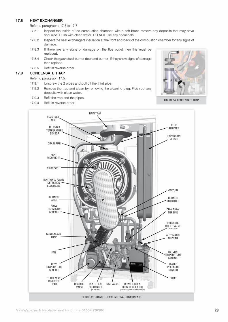
FIGURE 35. QUANTEC HR28C INTERNAL COMPONENTS
17.8 HEAT EXCHANGERRefer to paragraphs 17.5 to 17.7
17.8.1 Inspect the inside of the combustion chamber, with a soft brush remove any deposits that may have occurred. Flush with clean water. DO NOT use any chemicals.
17.8.2 Inspect the heat exchangers insulation at the front and back of the combustion chamber for any signs of damage.
17.8.3 If there are any signs of damage on the flue outlet then this must be replaced.
17.8.4 Check the gaskets of burner door and burner, If they show signs of damage then replace.
17.8.5 Refit in reverse order.
17.9 CONDENSATE TRAPRefer to paragraph 17.5.
17.9.1 Unscrew the 2 pipes and pull off the third pipe.
17.9.2 Remove the trap and clean by removing the cleaning plug. Flush out any deposits with clean water.
17.9.3 Refit the trap and the pipes.
17.9.4 Refit in reverse order.FIGURE 34. CONDENSATE TRAP
RETURNTEMPERATURE
SENSOR
DHW FLOWTURBINE
AUTOMATICAIR VENT
PRESSURERELIEF VALVE
(at the rear)
PUMP
GAS VALVE DHW FILTER &FLOW REGULATOR
(in front of plate heat exchanger)
PLATE HEATEXCHANGER
(at the rear)
FLOWTHERMISTOR
SENSOR
EXPANSION VESSEL
RAIN TRAP
IGNITION & FLAME DETECTIONELECTRODE
BURNER INJECTOR
VENTURI
VIEW PORT
BURNER ARM
HEATEXCHANGER
DRAIN PIPE
FLUE GASTEMPERATURE
SENSOR
FLUE TESTPOINT
FLUEADAPTER
CONDENSATE TRAP
FAN
DHW TEMPERATURE
SENSOR
WATERPRESSURE
SENSOR
THREE WAY DIVERTER
HEAD DIVERTERVALVE
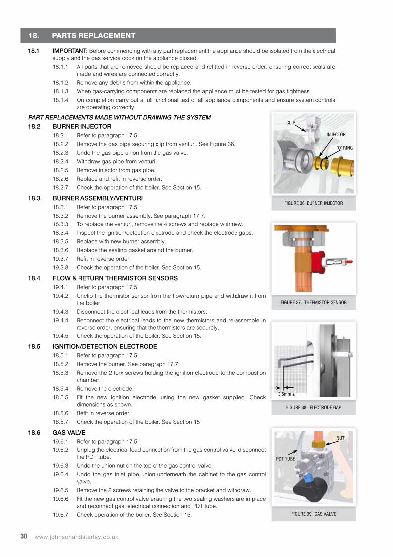
www.johnsonandstarley.co.uk30
18. PARTS REPLACEMENT
18.1 IMPORTANT: Before commencing with any part replacement the appliance should be isolated from the electrical supply and the gas service cock on the appliance closed.
18.1.1 All parts that are removed should be replaced and refitted in reverse order, ensuring correct seals are made and wires are connected correctly.
18.1.2 Remove any debris from within the appliance.
18.1.3 When gas-carrying components are replaced the appliance must be tested for gas tightness.
18.1.4 On completion carry out a full functional test of all appliance components and ensure system controls are operating correctly.
PART REPLACEMENTS MADE WITHOUT DRAINING THE SYSTEM
18.2 BURNER INJECTOR18.2.1 Refer to paragraph 17.5
18.2.2 Remove the gas pipe securing clip from venturi. See Figure 36.
18.2.3 Undo the gas pipe union from the gas valve.
18.2.4 Withdraw gas pipe from venturi.
18.2.5 Remove injector from gas pipe.
18.2.6 Replace and refit in reverse order.
18.2.7 Check the operation of the boiler. See Section 15.
18.3 BURNER ASSEMBLY/VENTURI18.3.1 Refer to paragraph 17.5
18.3.2 Remove the burner assembly. See paragraph 17.7.
18.3.3 To replace the venturi, remove the 4 screws and replace with new.
18.3.4 Inspect the ignition/detection electrode and check the electrode gaps.
18.3.5 Replace with new burner assembly.
18.3.6 Replace the sealing gasket around the burner.
19.3.7 Refit in reverse order.
19.3.8 Check the operation of the boiler. See Section 15.
18.4 FLOW & RETURN THERMISTOR SENSORS19.4.1 Refer to paragraph 17.5
19.4.2 Unclip the thermistor sensor from the flow/return pipe and withdraw it from the boiler.
19.4.3 Disconnect the electrical leads from the thermistors.
19.4.4 Reconnect the electrical leads to the new thermistors and re-assemble in reverse order, ensuring that the thermistors are securely.
19.4.5 Check the operation of the boiler. See Section 15.
18.5 IGNITION/DETECTION ELECTRODE18.5.1 Refer to paragraph 17.5
18.5.2 Remove the burner. See paragraph 17.7.
18.5.3 Remove the 2 torx screws holding the ignition electrode to the combustion chamber.
18.5.4 Remove the electrode.
18.5.5 Fit the new ignition electrode, using the new gasket supplied. Check dimensions as shown.
18.5.6 Refit in reverse order.
18.5.7 Check the operation of the boiler. See Section 15
18.6 GAS VALVE19.6.1 Refer to paragraph 17.5
19.6.2 Unplug the electrical lead connection from the gas control valve, disconnect the PDT tube.
19.6.3 Undo the union nut on the top of the gas control valve.
19.6.4 Undo the gas inlet pipe union underneath the cabinet to the gas control valve.
19.6.5 Remove the 2 screws retaining the valve to the bracket and withdraw.
19.6.6 Fit the new gas control valve ensuring the two sealing washers are in place and reconnect gas, electrical connection and PDT tube.
19.6.7 Check operation of the boiler. See Section 15.
FIGURE 38. ELECTRODE GAP
FIGURE 39. GAS VALVE
FIGURE 37. THERMISTOR SENSOR
FIGURE 36. BURNER INJECTOR
CLIP
INJECTOR
‘O’ RING
3.5mm ±1
PDT TUBE
NUT
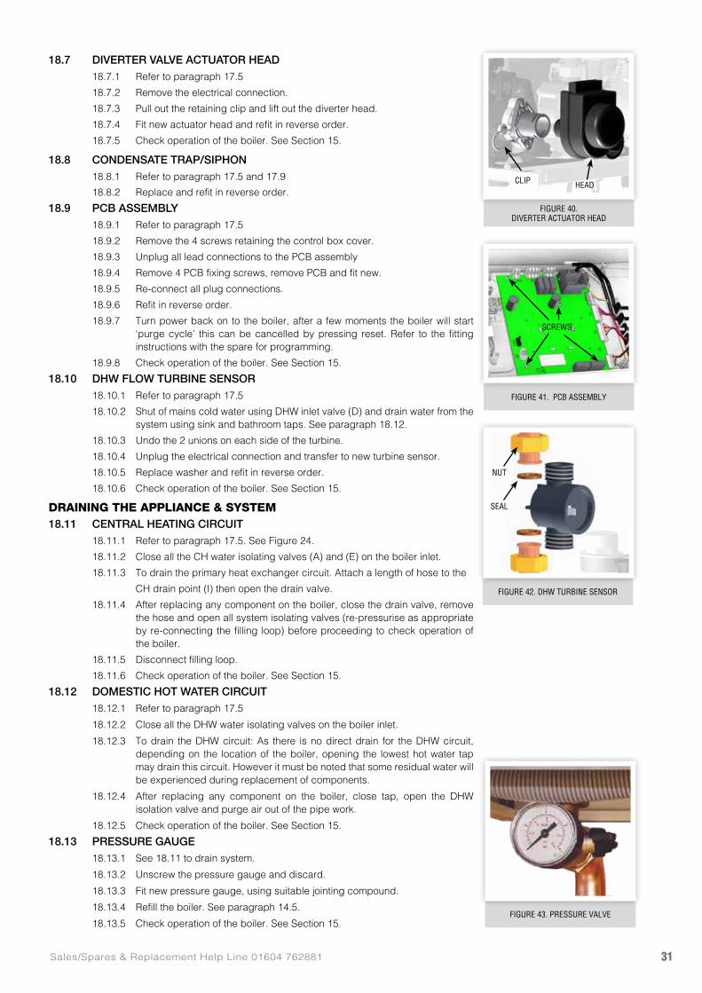
31Sales/Spares & Replacement Help Line 01604 762881
FIGURE 41. PCB ASSEMBLY
18.7 DIVERTER VALVE ACTUATOR HEAD18.7.1 Refer to paragraph 17.5
18.7.2 Remove the electrical connection.
18.7.3 Pull out the retaining clip and lift out the diverter head.
18.7.4 Fit new actuator head and refit in reverse order.
18.7.5 Check operation of the boiler. See Section 15.
18.8 CONDENSATE TRAP/SIPHON18.8.1 Refer to paragraph 17.5 and 17.9
18.8.2 Replace and refit in reverse order.
18.9 PCB ASSEMBLY18.9.1 Refer to paragraph 17.5
18.9.2 Remove the 4 screws retaining the control box cover.
18.9.3 Unplug all lead connections to the PCB assembly
18.9.4 Remove 4 PCB fixing screws, remove PCB and fit new.
18.9.5 Re-connect all plug connections.
18.9.6 Refit in reverse order.
18.9.7 Turn power back on to the boiler, after a few moments the boiler will start ‘purge cycle’ this can be cancelled by pressing reset. Refer to the fitting instructions with the spare for programming.
18.9.8 Check operation of the boiler. See Section 15.
18.10 DHW FLOW TURBINE SENSOR18.10.1 Refer to paragraph 17.5
18.10.2 Shut of mains cold water using DHW inlet valve (D) and drain water from the system using sink and bathroom taps. See paragraph 18.12.
18.10.3 Undo the 2 unions on each side of the turbine.
18.10.4 Unplug the electrical connection and transfer to new turbine sensor.
18.10.5 Replace washer and refit in reverse order.
18.10.6 Check operation of the boiler. See Section 15.
DRAINING THE APPLIANCE & SYSTEM18.11 CENTRAL HEATING CIRCUIT
18.11.1 Refer to paragraph 17.5. See Figure 24.
18.11.2 Close all the CH water isolating valves (A) and (E) on the boiler inlet.
18.11.3 To drain the primary heat exchanger circuit. Attach a length of hose to the
CH drain point (I) then open the drain valve.
18.11.4 After replacing any component on the boiler, close the drain valve, remove the hose and open all system isolating valves (re-pressurise as appropriate by re-connecting the filling loop) before proceeding to check operation of the boiler.
18.11.5 Disconnect filling loop.
18.11.6 Check operation of the boiler. See Section 15.
18.12 DOMESTIC HOT WATER CIRCUIT18.12.1 Refer to paragraph 17.5
18.12.2 Close all the DHW water isolating valves on the boiler inlet.
18.12.3 To drain the DHW circuit: As there is no direct drain for the DHW circuit, depending on the location of the boiler, opening the lowest hot water tap may drain this circuit. However it must be noted that some residual water will be experienced during replacement of components.
18.12.4 After replacing any component on the boiler, close tap, open the DHW isolation valve and purge air out of the pipe work.
18.12.5 Check operation of the boiler. See Section 15.
18.13 PRESSURE GAUGE18.13.1 See 18.11 to drain system.
18.13.2 Unscrew the pressure gauge and discard.
18.13.3 Fit new pressure gauge, using suitable jointing compound.
18.13.4 Refill the boiler. See paragraph 14.5.
18.13.5 Check operation of the boiler. See Section 15.
FIGURE 40. DIVERTER ACTUATOR HEAD
FIGURE 43. PRESSURE VALVE
CLIP
SCREWS
HEAD
FIGURE 42. DHW TURBINE SENSOR
SEAL
NUT
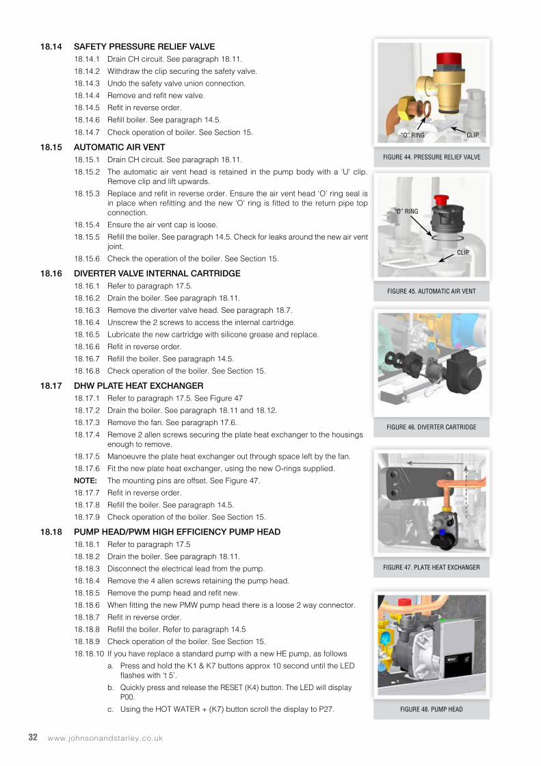
www.johnsonandstarley.co.uk32
18.14 SAFETY PRESSURE RELIEF VALVE18.14.1 Drain CH circuit. See paragraph 18.11.
18.14.2 Withdraw the clip securing the safety valve.
18.14.3 Undo the safety valve union connection.
18.14.4 Remove and refit new valve.
18.14.5 Refit in reverse order.
18.14.6 Refill boiler. See paragraph 14.5.
18.14.7 Check operation of boiler. See Section 15.
18.15 AUTOMATIC AIR VENT18.15.1 Drain CH circuit. See paragraph 18.11.
18.15.2 The automatic air vent head is retained in the pump body with a ‘U’ clip. Remove clip and lift upwards.
18.15.3 Replace and refit in reverse order. Ensure the air vent head ‘O’ ring seal is in place when refitting and the new ‘O’ ring is fitted to the return pipe top connection.
18.15.4 Ensure the air vent cap is loose.
18.15.5 Refill the boiler. See paragraph 14.5. Check for leaks around the new air vent joint.
18.15.6 Check the operation of the boiler. See Section 15.
18.16 DIVERTER VALVE INTERNAL CARTRIDGE18.16.1 Refer to paragraph 17.5.
18.16.2 Drain the boiler. See paragraph 18.11.
18.16.3 Remove the diverter valve head. See paragraph 18.7.
18.16.4 Unscrew the 2 screws to access the internal cartridge.
18.16.5 Lubricate the new cartridge with silicone grease and replace.
18.16.6 Refit in reverse order.
18.16.7 Refill the boiler. See paragraph 14.5.
18.16.8 Check operation of the boiler. See Section 15.
18.17 DHW PLATE HEAT EXCHANGER18.17.1 Refer to paragraph 17.5. See Figure 47
18.17.2 Drain the boiler. See paragraph 18.11 and 18.12.
18.17.3 Remove the fan. See paragraph 17.6.
18.17.4 Remove 2 allen screws securing the plate heat exchanger to the housings enough to remove.
18.17.5 Manoeuvre the plate heat exchanger out through space left by the fan.
18.17.6 Fit the new plate heat exchanger, using the new O-rings supplied.
NOTE: The mounting pins are offset. See Figure 47.
18.17.7 Refit in reverse order.
18.17.8 Refill the boiler. See paragraph 14.5.
18.17.9 Check operation of the boiler. See Section 15.
18.18 PUMP HEAD/PWM HIGH EFFICIENCY PUMP HEAD18.18.1 Refer to paragraph 17.5
18.18.2 Drain the boiler. See paragraph 18.11.
18.18.3 Disconnect the electrical lead from the pump.
18.18.4 Remove the 4 allen screws retaining the pump head.
18.18.5 Remove the pump head and refit new.
18.18.6 When fitting the new PMW pump head there is a loose 2 way connector.
18.18.7 Refit in reverse order.
18.18.8 Refill the boiler. Refer to paragraph 14.5
18.18.9 Check operation of the boiler. See Section 15.
18.18.10 If you have replace a standard pump with a new HE pump, as follows
a. Press and hold the K1 & K7 buttons approx 10 second until the LED flashes with ‘t 5’.
b. Quickly press and release the RESET (K4) button. The LED will display P00.
c. Using the HOT WATER + (K7) button scroll the display to P27.
FIGURE 44. PRESSURE RELIEF VALVE
FIGURE 47. PLATE HEAT EXCHANGER
FIGURE 48. PUMP HEAD
FIGURE 45. AUTOMATIC AIR VENT
FIGURE 46. DIVERTER CARTRIDGE
CLIP
CLIP
“O” RING
“O” RING
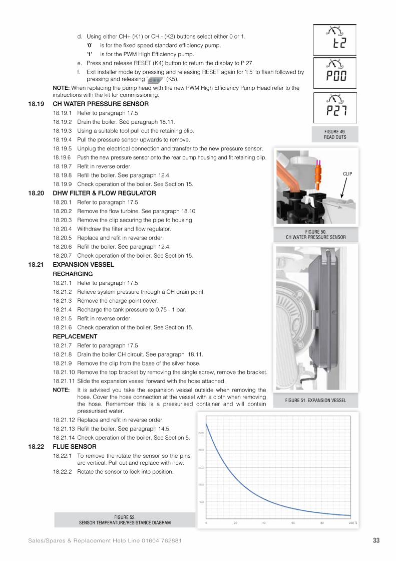
33Sales/Spares & Replacement Help Line 01604 762881
d. Using either CH+ (K1) or CH - (K2) buttons select either 0 or 1.
‘0’ is for the fixed speed standard efficiency pump.
‘1’ is for the PWM High Efficiency pump.
e. Press and release RESET (K4) button to return the display to P 27.
f. Exit installer mode by pressing and releasing RESET again for ‘t 5’ to flash followed by pressing and releasing ‘ ‘ (K5).
NOTE: When replacing the pump head with the new PWM High Efficiency Pump Head refer to the instructions with the kit for commissioning.
18.19 CH WATER PRESSURE SENSOR18.19.1 Refer to paragraph 17.5
18.19.2 Drain the boiler. See paragraph 18.11.
18.19.3 Using a suitable tool pull out the retaining clip.
18.19.4 Pull the pressure sensor upwards to remove.
18.19.5 Unplug the electrical connection and transfer to the new pressure sensor.
18.19.6 Push the new pressure sensor onto the rear pump housing and fit retaining clip.
18.19.7 Refit in reverse order.
18.19.8 Refill the boiler. See paragraph 12.4.
18.19.9 Check operation of the boiler. See Section 15.
18.20 DHW FILTER & FLOW REGULATOR18.20.1 Refer to paragraph 17.5
18.20.2 Remove the flow turbine. See paragraph 18.10.
18.20.3 Remove the clip securing the pipe to housing.
18.20.4 Withdraw the filter and flow regulator.
18.20.5 Replace and refit in reverse order.
18.20.6 Refill the boiler. See paragraph 12.4.
18.20.7 Check operation of the boiler. See Section 15.
18.21 EXPANSION VESSEL RECHARGING
18.21.1 Refer to paragraph 17.5
18.21.2 Relieve system pressure through a CH drain point.
18.21.3 Remove the charge point cover.
18.21.4 Recharge the tank pressure to 0.75 - 1 bar.
18.21.5 Refit in reverse order
18.21.6 Check operation of the boiler. See Section 15.
REPLACEMENT
18.21.7 Refer to paragraph 17.5
18.21.8 Drain the boiler CH circuit. See paragraph 18.11.
18.21.9 Remove the clip from the base of the silver hose.
18.21.10 Remove the top bracket by removing the single screw, remove the bracket.
18.21.11 Slide the expansion vessel forward with the hose attached.
NOTE: It is advised you take the expansion vessel outside when removing the hose. Cover the hose connection at the vessel with a cloth when removing the hose. Remember this is a pressurised container and will contain pressurised water.
18.21.12 Replace and refit in reverse order.
18.21.13 Refill the boiler. See paragraph 14.5.
18.21.14 Check operation of the boiler. See Section 5.
18.22 FLUE SENSOR18.22.1 To remove the rotate the sensor so the pins
are vertical. Pull out and replace with new.
18.22.2 Rotate the sensor to lock into position.
FIGURE 50.CH WATER PRESSURE SENSOR
FIGURE 49.READ OUTS
FIGURE 51. EXPANSION VESSEL
FIGURE 52.SENSOR TEMPERATURE/RESISTANCE DIAGRAM
CLIP
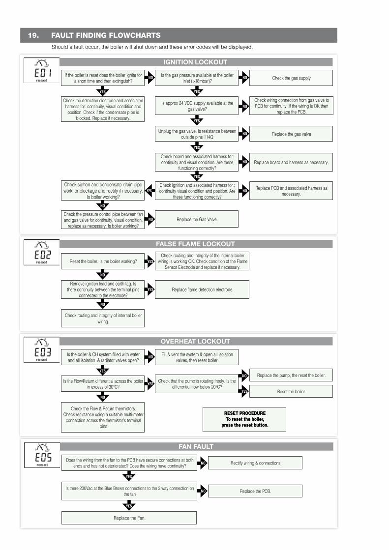
www.johnsonandstarley.co.uk34
19. FAULT FINDING FLOWCHARTS
Should a fault occur, the boiler will shut down and these error codes will be displayed.
IGNITION LOCKOUT
OVERHEAT LOCKOUT
FALSE FLAME LOCKOUT
YESYES
YES
NO
YES
YES
YES
NO
NO
NO
Check siphon and condensate drain pipe work for blockage and rectify if necessary.
Is boiler working?
Check routing and integrity of internal boiler wiring.
Check the gas supply
Check wiring connection from gas valve to PCB for continuity. If the wiring is OK then
replace the PCB.
Replace the pump, the reset the boiler.
Replace the gas valve
Replace board and harness as necessary.
Replace PCB and associated harness as necessary.
NO
NO
YES
YES
YES
YES
NO
NO
NO
NO
NO
NOYES
NOCheck the pressure control pipe between fan and gas valve for continuity, visual condition,
replace as necessary. Is boiler working?
Check the Flow & Return thermistors. Check resistance using a suitable multi-meter
connection across the thermistor’s terminal pins
RESET PROCEDURETo reset the boiler,
press the reset button.
Is the gas pressure available at the boiler inlet (>18mbar)?
Fill & vent the system & open all isolation valves, then reset boiler.
Check routing and integrity of the internal boiler wiring is working OK. Check condition of the Flame
Sensor Electrode and replace if necessary.
Is approx 24 VDC supply available at the gas valve?
Check that the pump is rotating freely. Is the differential now below 20°C?
Replace flame detection electrode.
Unplug the gas valve. Is resistance between outside pins 114Ω
Reset the boiler.
Check board and associated harness for: continuity and visual condition. Are these
functioning correctly?
Check ignition and associated harness for : continuity visual condition and position. Are
these functioning correctly?
Replace the Gas Valve.
If the boiler is reset does the boiler ignite for a short time and then extinguish?
Is the boiler & CH system filled with water and all isolation & radiator valves open?
Reset the boiler. Is the boiler working?
Check the detection electrode and associated harness for: continuity, visual condition and position. Check if the condensate pipe is
blocked. Replace if necessary.
Is the Flow/Return differential across the boiler in excess of 30°C?
Remove ignition lead and earth tag. Is there continuity between the terminal pins
connected to the electrode?
FAN FAULT
YES
YES
Replace the Fan.
NO
NO
Rectify wiring & connections
Replace the PCB.
Does the wiring from the fan to the PCB have secure connections at both ends and has not deteriorated? Does the wiring have continuity?
Is there 230Vac at the Blue Brown connections to the 3 way connection on the fan
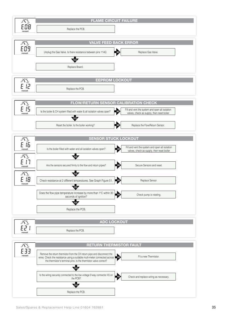
35Sales/Spares & Replacement Help Line 01604 762881
SENSOR STUCK LOCKOUT
RETURN THERMISTOR FAULT
FLOW/RETURN SENSOR CALIBRATION CHECK
VALVE FEED BACK ERROR
EEPROM LOCKOUT
ADC LOCKOUT
FLAME CIRCUIT FAILURE
YES
YES
YES
YES
YES
YES
YES
YES
Replace the PCB.
Check resistance at 2 different temperatures. See Graph Figure 51.
Replace the PCB.
Does the flow pipe temperature increase by more than 1°C within 30 seconds of ignition?
NO
NO
NO
NO
NO
NO
NO
NO
NO
Fit a new Thermistor.
Fill and vent the system and open all isolation valves, check as supply, then reset boiler
Replace Gas Valve.
Fill and vent the system and open all isolation valves, check as supply, then reset boiler
Check and replace wiring as necessary.
Replace the Flow/Return Sensor.
Secure Sensors and reset.
Replace Sensor.
Check pump is rotating.
Remove the return thermistor from the CH return pipe and disconnect the wires. Check the resistance using a suitable multi-meter connected across
the thermistor’s terminal pins. Is the thermistor valve correct?
Is the boiler & CH system filled with water & all isolation valves open?
Unplug the Gas Valve. Is there resistance between pins 114Ω.
Replace the PCB.
Replace the PCB.
Replace the PCB.
Is the boiler filled with water and all isolation valves open?
Is the wiring securely connected to the low voltage 9 way connector X5 on the PCB?
Reset the boiler. Is the boiler working?
Replace Board.
Are the sensors secured firmly to the flow and return pipes?
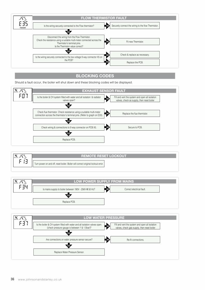
www.johnsonandstarley.co.uk36
Should a fault occur, the boiler will shut down and these blocking codes will be displayed.
FLOW THERMISTOR FAULT
YES
YES
Is the wiring securely connected to the low voltage 9 way connector X5 on the PCB?
NO
NO
Securely connect the wiring to the flow Thermistor.
Fit new Thermistor.
Is the wiring securely connected to the Flow thermistor?
Disconnect the wiring from the Flow Thermistor.Check the resistance using a suitable multi-meter connected across the
Thermistor’s terminal pins.Is the Thermistor value correct?
Check & replace as necessary.
YES
NO
Replace the PCB.
EXHAUST SENSOR FAULT
BLOCKING CODES
YES
YES
YES
Check wiring & connections to 9 way connector on PCB X5.
Replace PCB.
NO
NO
NO
Fill and vent the system and open all isolation valves, check as supply, then reset boiler
Replace the flue thermistor.
Secure to PCB.
Is the boiler & CH system filled with water and all isolation & radiator valves open?
Check flue thermistor. Check resistance using a suitable multi-meter connection across the thermistor’s terminal pins. (Refer to graph on E03).
REMOTE RESET LOCKOUT
Turn power on and off, reset boiler. Boiler will correct original lockout error.
LOW POWER SUPPLY FROM MAINS
YES
NO Correct electrical fault.Is mains supply to boiler between 190V - 256V @ 50 Hz?
Replace PCB.
LOW WATER PRESSURE
YES
YES
Replace Water Pressure Sensor.
NO
NO
Fill and vent the system and open all isolation valves, check gas supply, then reset boiler
Re-fit connections.
Is the boiler & CH system filled with water and all isolation valves open. (check pressure gauge is between 1 & 1.5bar)?
Are connections on water pressure sensor secure?
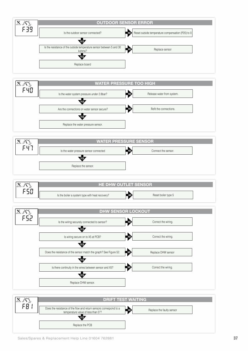
37Sales/Spares & Replacement Help Line 01604 762881
WATER PRESSURE TOO HIGH
DHW SENSOR LOCKOUT
HE DHW OUTLET SENSOR
DRIFT TEST WAITING
YES
YES
YES
YES
YES
YES
YES
Replace the water pressure sensor.
Does the resistance of the sensor match the graph? See Figure 52.
Is there continuity in the wires between sensor and X5?
Replace DHW sensor.
NO
NO
NO
NO
NO
NO
NO
NO
Release water from system.
Correct the wiring.
Correct the wiring.
Reset boiler type 5
Replace the faulty sensor
Refit the connections.
Replace DHW sensor
Correct the wiring.
Is the water system pressure under 2.8bar?
Is the wiring securely connected to sensor?
Is the boiler a system type with heat recovery?
Does the resistance of the flow and return sensors correspond to a temperature value of less than 5°?
Are the connections on water sensor secure?
Is wiring secure on to X5 at PCB?
Replace the PCB
OUTDOOR SENSOR ERROR
YES
YES
Replace board
bar0
1 2
3service
NO
NO
Reset outside temperature compensation (P20) to 0
Replace sensor
Is the outdoor sensor connected?
Is the resistance of the outside temperature sensor between 5 and 30 kohms?
WATER PRESSURE SENSOR
YES
NO Connect the sensor.Is the water pressure sensor connected
Replace the sensor.
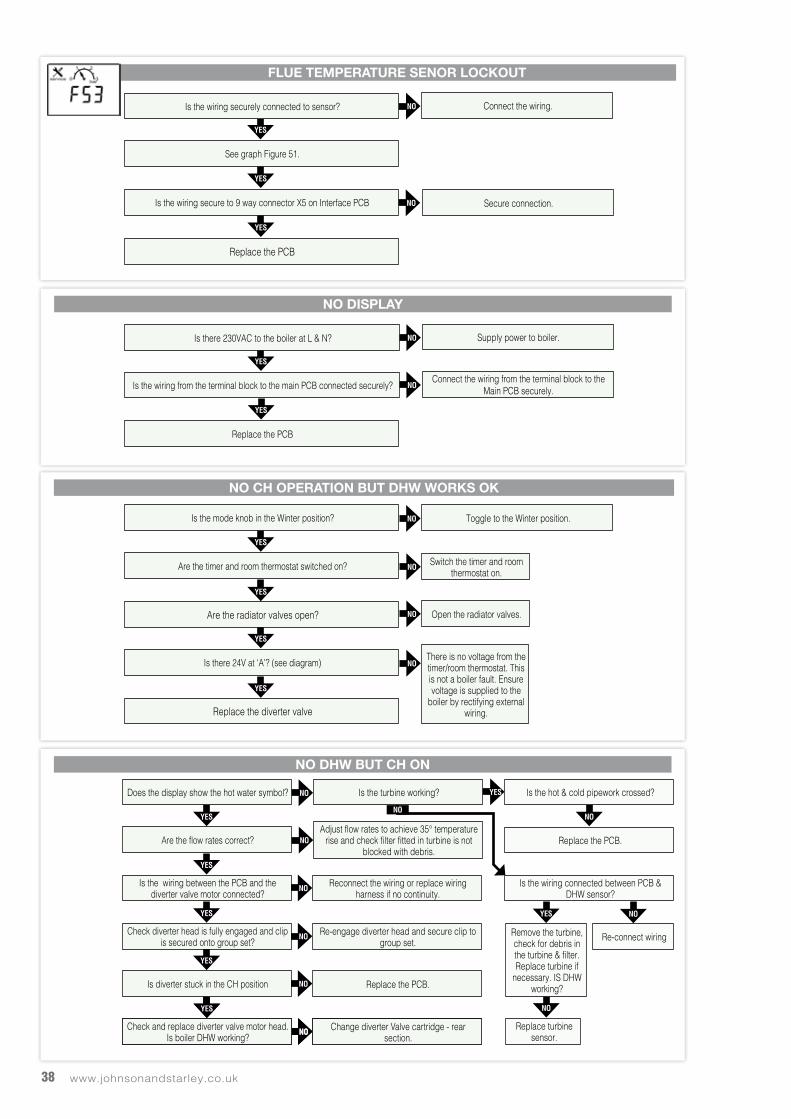
www.johnsonandstarley.co.uk38
FLUE TEMPERATURE SENOR LOCKOUT
NO DISPLAY
NO DHW BUT CH ON
YES
YES
YES
YES
YES
Is the wiring secure to 9 way connector X5 on Interface PCB
Replace the PCB
Replace the PCB
NO
NO
NO
NO
Connect the wiring.
Supply power to boiler.
Connect the wiring from the terminal block to the Main PCB securely.
Secure connection.
Is the wiring securely connected to sensor?
Is there 230VAC to the boiler at L & N?
See graph Figure 51.
Is the wiring from the terminal block to the main PCB connected securely?
NO CH OPERATION BUT DHW WORKS OK
YES
YES
YES
YES
Are the radiator valves open?
Replace the diverter valve
NO
NO
NO
NO
Toggle to the Winter position.
Switch the timer and room thermostat on.
There is no voltage from the timer/room thermostat. This is not a boiler fault. Ensure voltage is supplied to the
boiler by rectifying external wiring.
Open the radiator valves.
Is the mode knob in the Winter position?
Are the timer and room thermostat switched on?
Is there 24V at ‘A’? (see diagram)
YES NO
YES NO
NO
YES
YES
YESYES
YES
Is the hot & cold pipework crossed?
Replace the PCB.
Is the wiring connected between PCB & DHW sensor?
Re-connect wiring
Replace turbine sensor.
Remove the turbine, check for debris in the turbine & filter. Replace turbine if
necessary. IS DHW working?
NO
NO
NO
NO
NONO
NO
YESIs the turbine working?
Adjust flow rates to achieve 35° temperature rise and check filter fitted in turbine is not
blocked with debris.
Reconnect the wiring or replace wiring harness if no continuity.
Re-engage diverter head and secure clip to group set.
Change diverter Valve cartridge - rear section.
Change diverter Valve cartridge - rear section.
Replace the PCB.
Does the display show the hot water symbol?
Are the flow rates correct?
Is the wiring between the PCB and the diverter valve motor connected?
Check diverter head is fully engaged and clip is secured onto group set?
Check and replace diverter valve motor head. Is boiler DHW working?
Check and replace diverter valve motor head. Is boiler DHW working?
Is diverter stuck in the CH position
NO
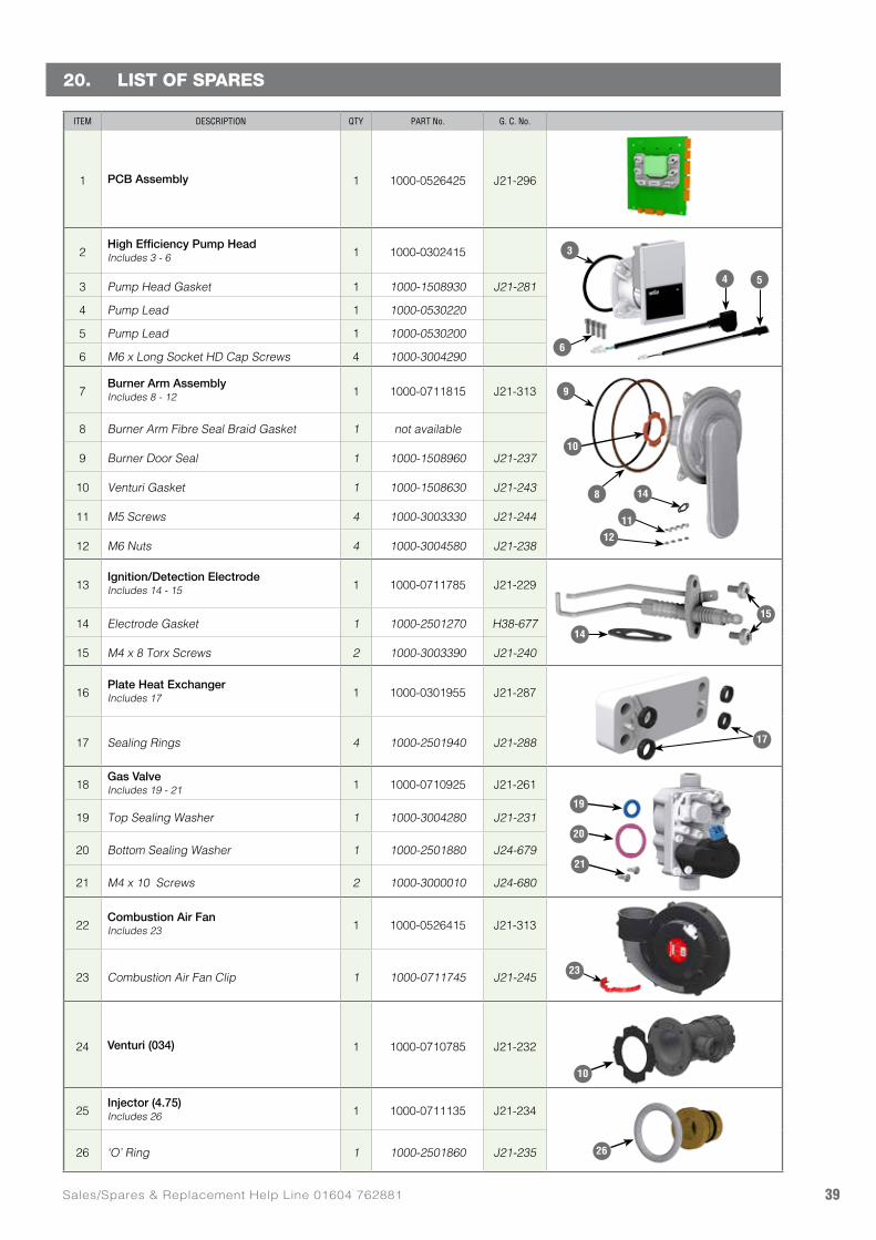
39Sales/Spares & Replacement Help Line 01604 762881
ITEM DESCRIPTION QTY PART No. G. C. No.
1 PCB Assembly 1 1000-0526425 J21-296
2High Efficiency Pump HeadIncludes 3 - 6 1 1000-0302415
3 Pump Head Gasket 1 1000-1508930 J21-281
4 Pump Lead 1 1000-0530220
5 Pump Lead 1 1000-0530200
6 M6 x Long Socket HD Cap Screws 4 1000-3004290
7Burner Arm AssemblyIncludes 8 - 12 1 1000-0711815 J21-313
8 Burner Arm Fibre Seal Braid Gasket 1 not available
9 Burner Door Seal 1 1000-1508960 J21-237
10 Venturi Gasket 1 1000-1508630 J21-243
11 M5 Screws 4 1000-3003330 J21-244
12 M6 Nuts 4 1000-3004580 J21-238
13Ignition/Detection ElectrodeIncludes 14 - 15 1 1000-0711785 J21-229
14 Electrode Gasket 1 1000-2501270 H38-677
15 M4 x 8 Torx Screws 2 1000-3003390 J21-240
16Plate Heat ExchangerIncludes 17 1 1000-0301955 J21-287
17 Sealing Rings 4 1000-2501940 J21-288
18Gas ValveIncludes 19 - 21 1 1000-0710925 J21-261
19 Top Sealing Washer 1 1000-3004280 J21-231
20 Bottom Sealing Washer 1 1000-2501880 J24-679
21 M4 x 10 Screws 2 1000-3000010 J24-680
22Combustion Air FanIncludes 23 1 1000-0526415 J21-313
23 Combustion Air Fan Clip 1 1000-0711745 J21-245
24 Venturi (034) 1 1000-0710785 J21-232
25Injector (4.75)Includes 26 1 1000-0711135 J21-234
26 ‘O’ Ring 1 1000-2501860 J21-235
20. LIST OF SPARES
23
9
8 14
10
12
3
6
54
11
14
15
19
20
21
26
10
17
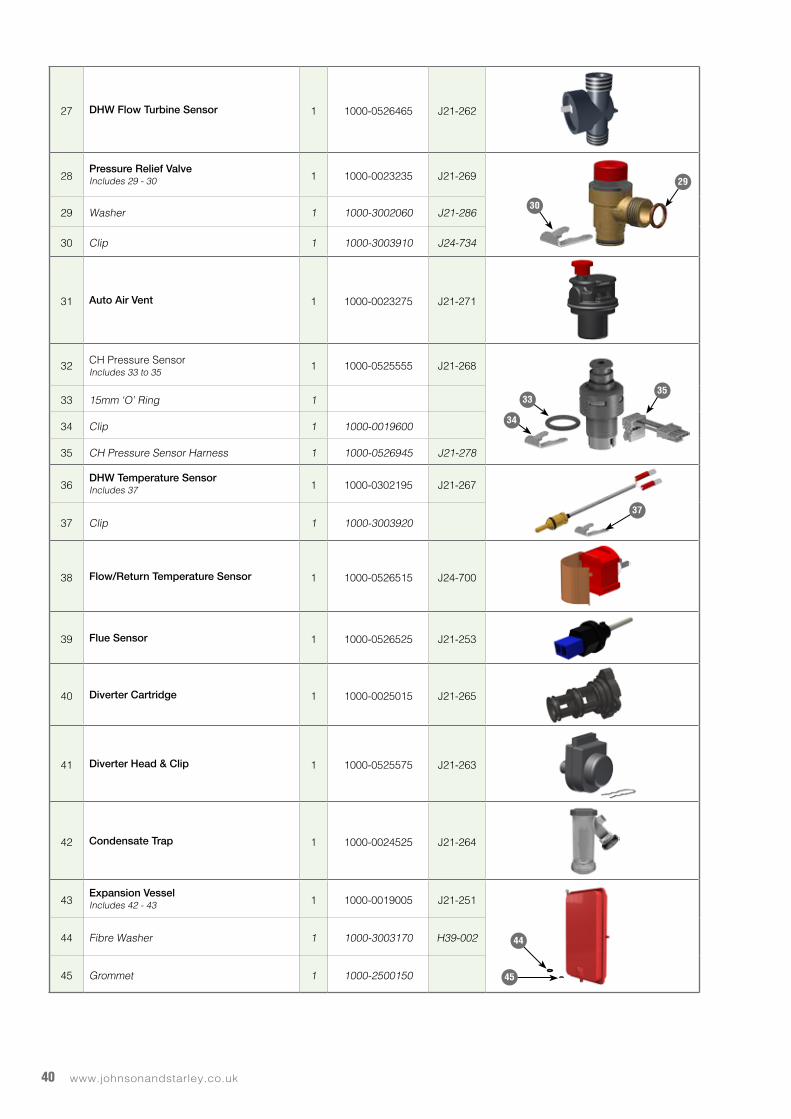
www.johnsonandstarley.co.uk40
27 DHW Flow Turbine Sensor 1 1000-0526465 J21-262
28Pressure Relief ValveIncludes 29 - 30 1 1000-0023235 J21-269
29 Washer 1 1000-3002060 J21-286
30 Clip 1 1000-3003910 J24-734
31 Auto Air Vent 1 1000-0023275 J21-271
32 CH Pressure SensorIncludes 33 to 35
1 1000-0525555 J21-268
33 15mm ‘O’ Ring 1
34 Clip 1 1000-0019600
35 CH Pressure Sensor Harness 1 1000-0526945 J21-278
36DHW Temperature SensorIncludes 37 1 1000-0302195 J21-267
37 Clip 1 1000-3003920
38 Flow/Return Temperature Sensor 1 1000-0526515 J24-700
39 Flue Sensor 1 1000-0526525 J21-253
40 Diverter Cartridge 1 1000-0025015 J21-265
41 Diverter Head & Clip 1 1000-0525575 J21-263
42 Condensate Trap 1 1000-0024525 J21-264
43Expansion VesselIncludes 42 - 43 1 1000-0019005 J21-251
44 Fibre Washer 1 1000-3003170 H39-002
45 Grommet 1 1000-2500150
44
45
29
30
33
34
35
37
Code Of PracticeFor the installation, commissioning and servicing of domestic heating and hot water products
Benchmark places responsibilities on both manufacturers and installers.* The purpose is to ensure that customers** are provided with the correct equipment for their needs, that it is installed, commissioned and serviced in accordance with the manufacturer’s instructions by competent persons and that it meets the requirements of the appropriate Building Regulations. Installers are required to carry out work in accordance with the following:
Standards of Work• Be competent and qualified to undertake the work
required.
• Install, commission, service and use products in accordance with the manufacturer’s instructions provided.
• Ensure that where there is responsibility for design work, the installation is correctly sized and fit for purpose.
• Meet the requirements of the appropriate Building Regulations. Where this involves notifiable work be a member of a Competent Persons Scheme or confirm that the customer has notified Local Authority Building Control (LABC), prior to work commencing.
• Complete all relevant sections of the Benchmark Checklist/Service Record when carrying out commissioning or servicing of a product or system.
• Ensure that the product or system is left in a safe condition and, whenever possible, in good working order.
• Highlight to the customer any remedial or improvement work identified during the course of commissioning or servicing work.
• Refer to the manufacturer’s helpline where assistance is needed.
• Report product faults and concerns to the manufacturer in a timely manner.
Customer Service• Show the customer any identity card that is relevant to
the work being carried out prior to commencement or on request.
• Give a full and clear explanation/demonstration of the product or system and its operation to the customer.
• Hand over the manufacturer’s instructions, including the Benchmark Checklist, to the customer on completion of an installation.
• Obtain the customer’s signature, on the Benchmark Checklist, to confirm satisfactory demonstration and receipt of manufacturer’s instructions.
• Advise the customer that regular product servicing is needed, in line with manufacturers’ recommendations, to ensure that safety and efficiency is maintained.
• Respond promptly to calls from a customer following completion of work, providing advice and assistance by phone and, if necessary, visiting the customer.
• Rectify any installation problems at no cost to the customer during the installer’s guarantee period.
* The use of the word “installer” is not limited to installation itself and covers those carrying out installation, commissioning and/or servicing of heating and hot water products, or the use of supporting products (such as water treatment or test equipment).
**Customer includes householders, landlords and tenants.
© Heating and Hotwater Industry Council (HHIC) www.centralheating.co.uk
M15262_Code_of_Practice.indd 1 6/12/07 15:57:01
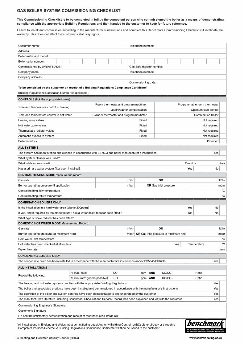
*All installations in England and Wales must be to Local Authority Building Control (LABC) either directly or through aCompetent Persons Scheme. A Building Regulations Compliance will then be issued to the customer.
www.centralheating.co.uk© Heating and Hotwater Industry Council (HHIC)
This Commissioning Checklist is to be completed in full by the competent person who commissioned the boiler as a means of demonstrating compliance with the appropriate Building Regulations and then handed to the customer to keep for future reference.
Failure to install and commission according to the manufacturer’s instructions and complete this Benchmark Commissioning Checklist will invalidate the warranty. This does not affect the customer’s statutory rights.
GAS BOILER SYSTEM COMMISSIONING CHECKLIST
Customer name: Telephone number:
Address:
Boiler make and model:
Boiler serial number:
Commissioned by (PRINT NAME): Gas Safe register number:
Company name: Telephone number:
Company address:
Commissioning date:
CONTROLS (tick the appropriate boxes)
Time and temperature control to heatingRoom thermostat and programmer/timer Programmable room thermostat
Load/weather compensation Optimum start control
Time and temperature control to hot water Cylinder thermostat and programmer/timer Combination Boiler
Heating zone valves Fitted Not required
Hot water zone valves Fitted Not required
Thermostatic radiator valves Fitted Not required
Automatic bypass to system Fitted Not required
Boiler interlock Provided
ALL SYSTEMS
’s instructions Yes
What system cleaner was used?
What inhibitor was used? Quantity litres
Yes No
CENTRAL HEATING MODE measure and record:
Gas rate m³/hr OR ft³/hr
Burner operating pressure (if applicable) mbar OR Gas inlet pressure mbar
°C
Central heating return temperature °C
COMBINATION BOILERS ONLY
Is the installation in a hard water area (above 200ppm)? Yes No
Yes No
DOMESTIC HOT WATER MODE Measure and Record:
Gas rate m³/hr OR ft³/hr
Burner operating pressure (at maximum rate) mbar OR Gas inlet pressure at maximum rate mbar
Cold water inlet temperature °C
Hot water has been checked at all outlets Yes Temperature °C
I/min
CONDENSING BOILERS ONLY
The condensate drain has been installed in accordance with the manufacturer’s instructions and/or BS5546/BS6798 Yes
ALL INSTALLATIONS
Record the following:At max. rate: CO ppm AND CO/CO² Ratio
At min. rate: (where possible) CO ppm AND CO/CO² Ratio
The heating and hot water system complies with the appropriate Building Regulations Yes
The boiler and associated products have been installed and commissioned in accordance with the manufacturer’s instructions Yes
The operation of the boiler and system controls have been demonstrated to and understood by the customer Yes
The manufacturer’s literature, including Benchmark Checklist and Service Record, has been explained and left with the customer Yes
Commissioning Engineer’s Signature
Customer’s Signature
www.centralheating.co.uk
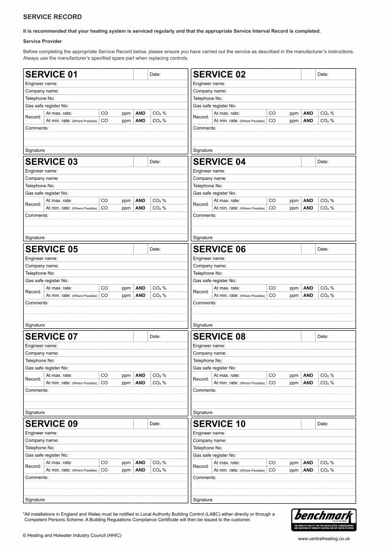
www.centralheating.co.uk
It is recommended that your heating system is serviced regularly and that the appropriate Service Interval Record is completed.
Service Provider
Before completing the appropriate Service Record below, please ensure you have carried out the service as described in the manufacturer’s instructions.
SERVICE RECORD
SERVICE 01 Date:
Engineer name:Company name:Telephone No:Gas safe register No:
Record:At max. rate: CO ppm AND CO² %At min. rate: (Where Possible) CO ppm AND CO² %
Comments:
Signature
SERVICE 02 Date:
Engineer name:Company name:Telephone No:Gas safe register No:
Record:At max. rate: CO ppm AND CO² %At min. rate: (Where Possible) CO ppm AND CO² %
Comments:
Signature
SERVICE 03 Date:
Engineer name:Company name:Telephone No:Gas safe register No:
Record:At max. rate: CO ppm AND CO² %At min. rate: (Where Possible) CO ppm AND CO² %
Comments:
Signature
SERVICE 04 Date:
Engineer name:Company name:Telephone No:Gas safe register No:
Record:At max. rate: CO ppm AND CO² %At min. rate: (Where Possible) CO ppm AND CO² %
Comments:
Signature
SERVICE 05 Date:
Engineer name:Company name:Telephone No:Gas safe register No:
Record:At max. rate: CO ppm AND CO² %At min. rate: (Where Possible) CO ppm AND CO² %
Comments:
Signature
SERVICE 06 Date:
Engineer name:Company name:Telephone No:Gas safe register No:
Record:At max. rate: CO ppm AND CO² %At min. rate: (Where Possible) CO ppm AND CO² %
Comments:
Signature
SERVICE 07 Date:
Engineer name:Company name:Telephone No:Gas safe register No:
Record:At max. rate: CO ppm AND CO² %At min. rate: (Where Possible) CO ppm AND CO² %
Comments:
Signature
SERVICE 08 Date:
Engineer name:Company name:Telephone No:Gas safe register No:
Record:At max. rate: CO ppm AND CO² %At min. rate: (Where Possible) CO ppm AND CO² %
Comments:
Signature
SERVICE 09 Date:
Engineer name:Company name:Telephone No:Gas safe register No:
Record:At max. rate: CO ppm AND CO² %At min. rate: (Where Possible) CO ppm AND CO² %
Comments:
Signature
SERVICE 10 Date:
Engineer name:Company name:Telephone No:Gas safe register No:
Record:At max. rate: CO ppm AND CO² %At min. rate: (Where Possible) CO ppm AND CO² %
Comments:
Signature
*All installations in England and Wales must be to Local Authority Building Control (LABC) either directly or through aCompetent Persons Scheme. A Building Regulations Compliance will then be issued to the customer.
© Heating and Hotwater Industry Council (HHIC)

Johnson & Starley LtdRhosili Road, Brackmills,Northampton NN4 7LZ
[email protected]@johnsonandstarley.co.uk
Reception/Customer Service01604 762881
Fax01604 767408
Anniversary 1922 - 2012
In the interest of continuous development Johnson & Starley reserve the right to change specifications without prior notice.