princess sumaya university for technology computer organization and architecture i princess sumaya...
Post on 21-Dec-2015
228 views
TRANSCRIPT
Introduction to Verilog Hardware Description Language
Dr. Esam Al-Qaralleh
Introduction
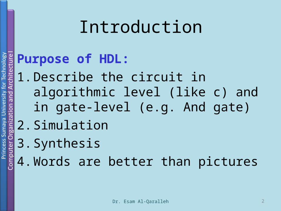
Purpose of HDL:1. Describe the circuit in algorithmic level (like
c) and in gate-level (e.g. And gate)2. Simulation3. Synthesis4. Words are better than pictures
Dr. Esam Al-Qaralleh 2
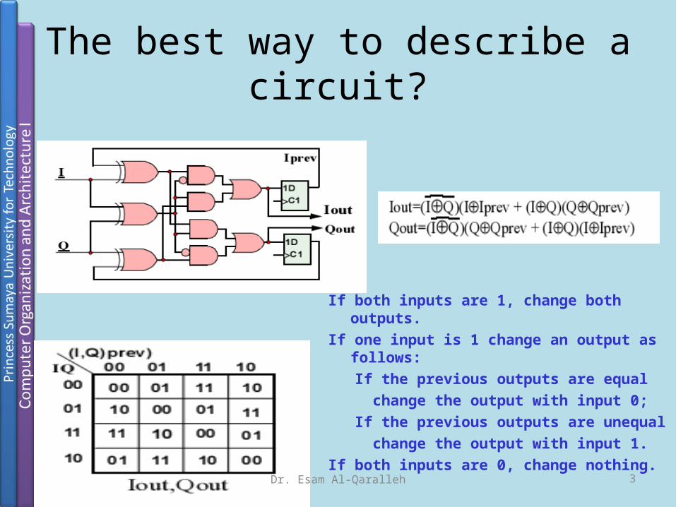
The best way to describe a circuit?
If both inputs are 1, change both outputs.If one input is 1 change an output as follows: If the previous outputs are equal change the output with input 0; If the previous outputs are unequal change the output with input 1.If both inputs are 0, change nothing.
Dr. Esam Al-Qaralleh 3

Verilog Basics
Dr. Esam Al-Qaralleh 4
helloWorld.v
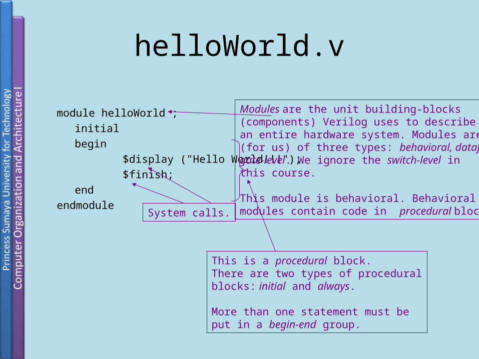
module helloWorld ; initial begin
$display ("Hello World!!!");$finish;
endendmodule
This is a procedural block.There are two types of proceduralblocks: initial and always.
More than one statement must beput in a begin-end group.
Modules are the unit building-blocks(components) Verilog uses to describe an entire hardware system. Modules are(for us) of three types: behavioral, dataflow, gate-level. We ignore the switch-level in this course.
This module is behavioral. Behavioral modules contain code in procedural blocks.System calls.
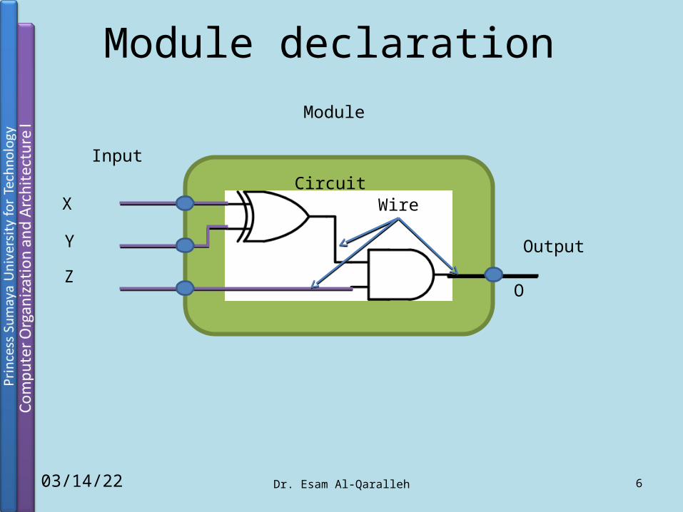
Module declaration
Dr. Esam Al-Qaralleh 604/18/23
Module
Circuit
Input
X
Y
Z
Output
O
Wire

Module declaration
Dr. Esam Al-Qaralleh 704/18/23
Module
Circuit
Input
X
Y
Z
Output
O
Wire
module sample (X,Y,Z,O);
input X,Y,Z;output O;
// Describe the circuit using logic symbols assign O = (X^Y)&Z;
endmodule
Module name

Typical Module Components Diagram
Module name, Port list (optional, if there are ports)
Port declarations Parameter list
Declaration of variables (wires, reg, integer etc.)
Instantiation of inner (lower-level) modules
Structural statements (i.e., assign and gates)
Procedural blocks (i.e., always and initial blocks)
Tasks and functions
endmodule declaration

Lexicography
• Comments:Two Types:• // Comment• /* These comments extend over multiple lines. Good
for commenting out code */
• Character Set:0123456789ABCD..YZabcd...yz_$Cannot start with a number or $
Dr. Esam Al-Qaralleh 9

systemCalls.vmodule systemCalls(clk); input clk; clockGenerator cg(clk);
initial begin #25 $stop; #50 $finish; end
initial begin $write("$write does not "); $write("add a new line\n");
$display("$display does"); $display("add a new line"); $monitor("Clock = %d", cg.clk); endendmodule
Compile with the clockGenerator.v module.
Suspends simulation – enters interactive mode.
Terminates simulation.
Similar output calls except$display adds a new line.
$monitor produces outputeach time a variable changesvalue.

2005 Verilog HDL11
Data Types
• Nets and Registers• Vectors• Integer, Real, and Time Register Data Types• Arrays• Memories• Parameters• Strings
2005 Verilog HDL12
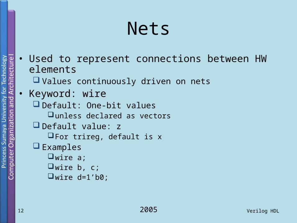
Nets• Used to represent connections between HW elements
Values continuously driven on nets• Keyword: wire
Default: One-bit valuesunless declared as vectors
Default value: zFor trireg, default is x
Exampleswire a;wire b, c;wire d=1’b0;
2005 Verilog HDL13
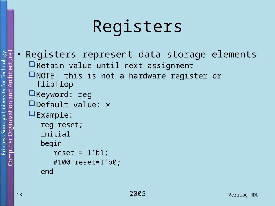
Registers
• Registers represent data storage elementsRetain value until next assignmentNOTE: this is not a hardware register or flipflopKeyword: regDefault value: xExample:
reg reset;initial begin reset = 1’b1; #100 reset=1’b0;end

2005 Verilog HDL14
Vectors
• Net and register data types can be declared as vectors (multiple bit widths)
• Syntax: wire/reg [msb_index : lsb_index] data_id;
• Examplewire a;
wire [7:0] bus;
wire [31:0] busA, busB, busC;
reg clock;
reg [0:40] virtual_addr;

2005 Verilog HDL15
Vectors (cont’d)
• Considerwire [7:0] bus;wire [31:0] busA, busB, busC;reg [0:40] virtual_addr;
• Access to bits or parts of a vector is possible:busA[7]bus[2:0] // three least-significant bits of bus// bus[0:2] is illegal.virtual_addr[0:1] /* two most-significant bits * of virtual_addr */

2005 Verilog HDL16
Integer, Real, and Time Register Data Types
• IntegerKeyword: integerVery similar to a vector of reg
integer variables are signed numbersreg vectors are unsigned numbers
Bit width: implementation-dependent (at least 32-bits)Designer can also specify a width:
integer [7:0] tmp;
Examples:integer counter;initial counter = -1;

2005 Verilog HDL17
Integer, Real, and Time Register Data Types (cont’d)
• Real Keyword: real Values:
Default value: 0 Decimal notation: 12.24 Scientific notation: 3e6 (=3x10⁶)
Cannot have range declaration Example:
real delta;initialbegin delta=4e10; delta=2.13;endinteger i;initial i = delta; // i gets the value 2 (rounded value of 2.13)

2005 Verilog HDL18
Integer, Real, and Time Register Data Types (cont’d)
• TimeUsed to store values of simulation timeKeyword: timeBit width: implementation-dependent (at least 64)$time system function gives current simulation timeExample:
time save_sim_time;initial save_sim_time = $time;

2005 Verilog HDL19
Arrays• Only one-dimensional arrays supported• Allowed for reg, integer, time
Not allowed for real data type• Syntax:
<data_type> <var_name>[start_idx : end_idx];• Examples:
integer count[0:7];reg bool[31:0];time chk_point[1:100];reg [4:0] port_id[0:7];integer matrix[4:0][4:0]; // illegal
count[5]chk_point[100]port_id[3]
• Note the difference between vectors and arrays

2005 Verilog HDL20
Memories• RAM, ROM, and register-files used many times in digital
systems• Memory = array of registers in Verilog• Word = an element of the array
Can be one or more bits• Examples:
reg membit[0:1023];reg [7:0] membyte[0:1023];membyte[511]
• Note the difference (as in arrays):reg membit[0:127];reg [0:127] register;
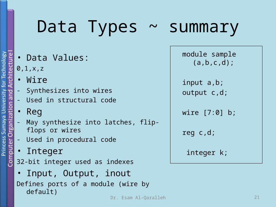
Data Types ~ summary
• Data Values:0,1,x,z
• Wire- Synthesizes into wires- Used in structural code
• Reg- May synthesize into latches, flip-flops or wires- Used in procedural code
• Integer32-bit integer used as indexes
• Input, Output, inoutDefines ports of a module (wire by default)
module sample (a,b,c,d);
input a,b;output c,d;
wire [7:0] b;
reg c,d;
integer k;
Dr. Esam Al-Qaralleh 21

4valuedLogic.v
module fourValues( a , b, c, d ); output a, b, c, d ;
assign a = 1; assign b = 0; assign c = a; assign c = b;endmodule
module stimulus; fourValues X(a, b, c, d);
initial begin #1 $display("a = %d b = %d, c = %d, d = %d", a, b, c, d); $finish; endendmodule
4-valued logic:0 – low1 – highx – unknownz – undriven wire Now explain output!
Conflict or race condition.Remember this isnot a procedural(i.e., sequential) block! These arecontinuous assign-ments.

Data Values
• Numbers:Numbers are defined by number of
bits Value of 23:5’b10111 // Binary5’d23 // Decimal5’h17 // Hex
• Constants:wire [3:0] t,d;assign t = 23;assign d= 4’b0111;
• Parameters:
parameter n=4;wire [n-1:0] t, d;
`define Reset_state = 0, state_B =1, Run_state =2, finish_state = 3;
if(state==`Run_state)
Dr. Esam Al-Qaralleh 23
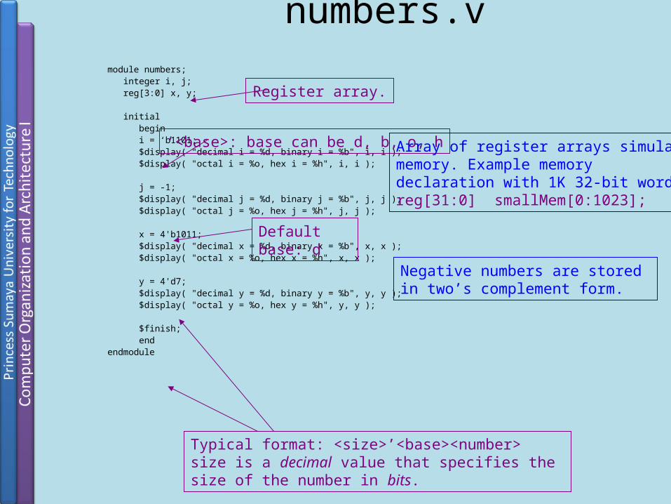
numbers.vmodule numbers; integer i, j; reg[3:0] x, y;
initial begin i = ‘b1101; $display( "decimal i = %d, binary i = %b", i, i ); $display( "octal i = %o, hex i = %h", i, i );
j = -1; $display( "decimal j = %d, binary j = %b", j, j ); $display( "octal j = %o, hex j = %h", j, j );
x = 4'b1011; $display( "decimal x = %d, binary x = %b", x, x ); $display( "octal x = %o, hex x = %h", x, x );
y = 4'd7; $display( "decimal y = %d, binary y = %b", y, y ); $display( "octal y = %o, hex y = %h", y, y );
$finish; endendmodule
‘<base>: base can be d, b, o, h
Default base: d
Typical format: <size>’<base><number>size is a decimal value that specifies the size of the number in bits.
Register array.
Negative numbers are stored in two’s complement form.
Array of register arrays simulatememory. Example memorydeclaration with 1K 32-bit words:reg[31:0] smallMem[0:1023];

Operators• Arithmetic:*,+,-, /,%• Relational<,<=,>,>=,==, !=• Bit-wise Operators
• Not: ~ • XOR: ^• And : & 5’b11001 & 5’b01101 ==> 5’b01001• OR: | • XNOR: ~^ or ^~
• Logical OperatorsReturns 1or 0, treats all nonzero as 1
• ! : Not • && : AND 27 && -3 ==> 1• || : OR
reg [3:0] a, b, c, d;wire[7:0] x,y,z;parameter n =4;
c = a + b;d = a *n;
If(x==y) d = 1; else d =0;
d = a ~^ b;
if ((x>=y) && (z)) a=1; else a = !x;
Dr. Esam Al-Qaralleh 25
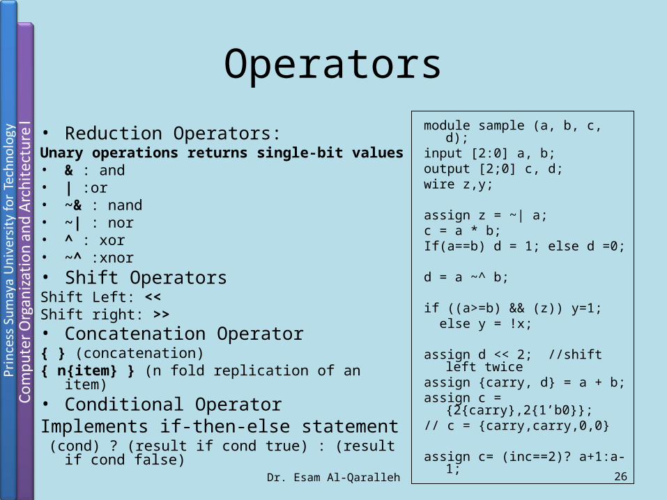
Operators• Reduction Operators:Unary operations returns single-bit values• & : and• | :or• ~& : nand• ~| : nor• ^ : xor• ~^ :xnor• Shift OperatorsShift Left: <<Shift right: >>• Concatenation Operator { } (concatenation){ n{item} } (n fold replication of an item)• Conditional OperatorImplements if-then-else statement (cond) ? (result if cond true) : (result if cond false)
module sample (a, b, c, d);input [2:0] a, b;output [2;0] c, d;wire z,y;
assign z = ~| a;c = a * b;If(a==b) d = 1; else d =0;
d = a ~^ b;
if ((a>=b) && (z)) y=1; else y = !x;
assign d << 2; //shift left twiceassign {carry, d} = a + b;assign c = {2{carry},2{1’b0}};// c = {carry,carry,0,0}
assign c= (inc==2)? a+1:a-1; Dr. Esam Al-Qaralleh 26

module clockGenerator(clk); output clk; reg clk;
initial begin clk = 0; end
always #5 clk = ~clk;endmodule
The delay is half the clock period.
If this module is run stand-alone makesure to add a $finish statement here or simulation will never complete!
Internal register.
Register reg data type can have one offour values: 0, 1, x, z. Registers store avalue till the next assignment. Registersare assigned values in procedural blocks.
clockGenerator.vPort list. Ports can be of three types: input,output, inout. Each must be declared.

Verilog Structure
• All code are contained in modules
• Can invoke other modules
• Modules cannot be contained in another module
ACB
Dr. Esam Al-Qaralleh 28
module gate(Z,A,B,C);input A,B,C;output Z;assign Z = A|(B&C);Endmodule
module two_gates(Z2,A2,B2,C2)input A2,B2,C2;output Z2;gate gate_1(G2,A2,B2,C2);gate gate_2(Z2,G2,A2,B2);endmodule
A2C2B2
B2A2
Z

Structural Vs Procedural Structural
• textual description of circuit• order does not matter
• Starts with assign statements
• Harder to code• Need to work out logic
Procedural• Think like C code
• Order of statements are important
• Starts with initial or always statement
• Easy to code• Can use case, if, for
Dr. Esam Al-Qaralleh 29
wire c, d;assign c =a & b;assign d = c |b;
reg c, d;always@ (a or b or c) begin
c =a & b;d = c |b;
end

Structural Vs ProceduralProcedural
reg [3:0] Q;wire [1:0] y;always@(y) begin Q=4’b0000; case(y) begin 2’b00: Q[0]=1; 2’b01: Q[1]=1; 2’b10: Q[2]=1; 2’b11: Q[3]=1; endcaseend
Structuralwire [3:0]Q;wire [1:0]y;assign Q[0]=(~y[1])&(~y[0]), Q[1]=(~y[1])&y[0], Q[2]=y[1]&(~y[0]), Q[3]=y[1]&y[0];
You don’thave to
work outlogic
y[0]
y[1]
Q[0]
Q[1]
Q[2]
Q[3]y[0]
y[1]
Q[0]
Q[1]
Q[2]
Q[3]
Dr. Esam Al-Qaralleh 30

Blocking Vs Non-Blocking
Dr. Esam Al-Qaralleh 31
Blocking <variable> = <statement>
Similar to C code
The next assignment waits until the present one is finished
Used for combinational logic
Non-blocking <variable> <= <statement>
The inputs are stored once the procedure is triggered
Statements are executed in parallel
Used for flip-flops, latches and registers
Do not mix both assignments in one procedure
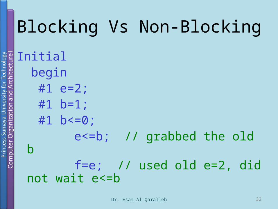
Blocking Vs Non-Blocking
Initial begin #1 e=2; #1 b=1; #1 b<=0; e<=b; // grabbed the old b f=e; // used old e=2, did not wait e<=b
Dr. Esam Al-Qaralleh 32
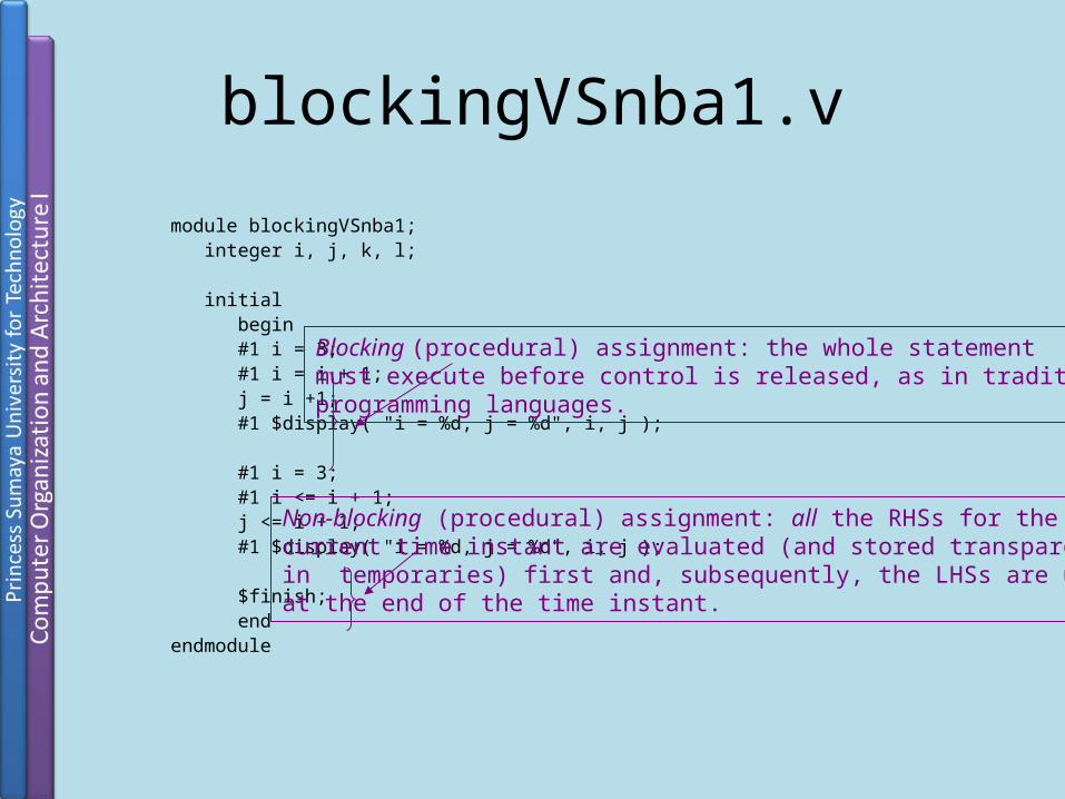
blockingVSnba1.v
module blockingVSnba1; integer i, j, k, l;
initial begin #1 i = 3; #1 i = i + 1; j = i +1; #1 $display( "i = %d, j = %d", i, j );
#1 i = 3; #1 i <= i + 1; j <= i + 1; #1 $display( "i = %d, j = %d", i, j );
$finish; endendmodule
Blocking (procedural) assignment: the whole statementmust execute before control is released, as in traditionalprogramming languages.
Non-blocking (procedural) assignment: all the RHSs for the current time instant are evaluated (and stored transparentlyin temporaries) first and, subsequently, the LHSs are updatedat the end of the time instant.
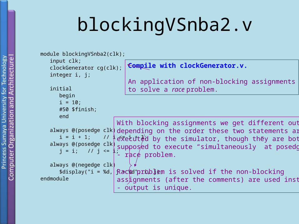
blockingVSnba2.vmodule blockingVSnba2(clk); input clk; clockGenerator cg(clk); integer i, j; initial begin i = 10; #50 $finish; end
always @(posedge clk) i = i + 1; // i <= i + 1; always @(posedge clk) j = i; // j <= i;
always @(negedge clk) $display("i = %d, j = %d", i, j);endmodule
Compile with clockGenerator.v.
An application of non-blocking assignmentsto solve a race problem.
With blocking assignments we get different output depending on the order these two statements areexecuted by the simulator, though they are both supposed to execute “simultaneously” at posedge clk- race problem.
Race problem is solved if the non-blocking assignments (after the comments) are used instead- output is unique.
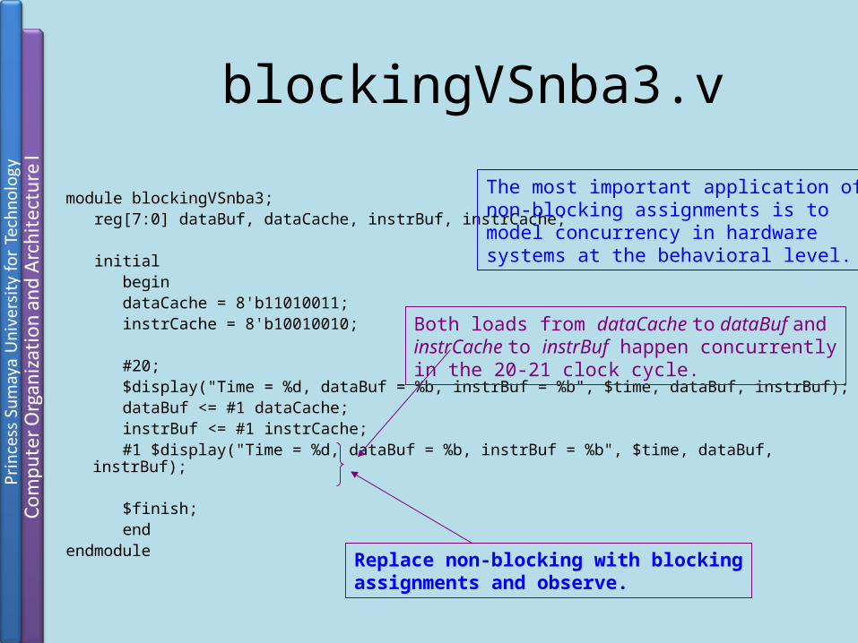
blockingVSnba3.v
module blockingVSnba3; reg[7:0] dataBuf, dataCache, instrBuf, instrCache;
initial begin dataCache = 8'b11010011; instrCache = 8'b10010010;
#20; $display("Time = %d, dataBuf = %b, instrBuf = %b", $time, dataBuf, instrBuf); dataBuf <= #1 dataCache; instrBuf <= #1 instrCache; #1 $display("Time = %d, dataBuf = %b, instrBuf = %b", $time, dataBuf, instrBuf);
$finish; endendmodule
Both loads from dataCache to dataBuf andinstrCache to instrBuf happen concurrentlyin the 20-21 clock cycle.
The most important application ofnon-blocking assignments is to model concurrency in hardware systems at the behavioral level.
Replace non-blocking with blockingassignments and observe.
System Tasks and Compiler Directives

2005 Verilog HDL37
System Tasks
• System Tasks: standard routine operations provided by VerilogDisplaying on screen, monitoring values, stopping
and finishing simulation, etc.
• All start with $

2005 Verilog HDL38
System Tasks (cont’d)• $display: displays values of variables, strings, expressions.
Syntax: $display(p1, p2, p3, …, pn); p1,…, pn can be quoted string, variable, or expression Adds a new-line after displaying pn by default Format specifiers:
%d, %b, %h, %o: display variable respectively in decimal, binary, hex, octal
%c, %s: display character, string%e, %f, %g: display real variable in scientific, decimal, or whichever
smaller notation%v: display strength%t: display in current time format%m: display hierarchical name of this module

2005 Verilog HDL39
System Tasks (cont’d)• $display examples:
$display(“Hello Verilog World!”);Output: Hello Verilog World!
$display($time);Output: 230
reg [0:40] virtual_addr; $display(“At time %d virtual address is %h”, $time, virtual_addr);
Output: At time 200 virtual address is 1fe000001c
2005 Verilog HDL40
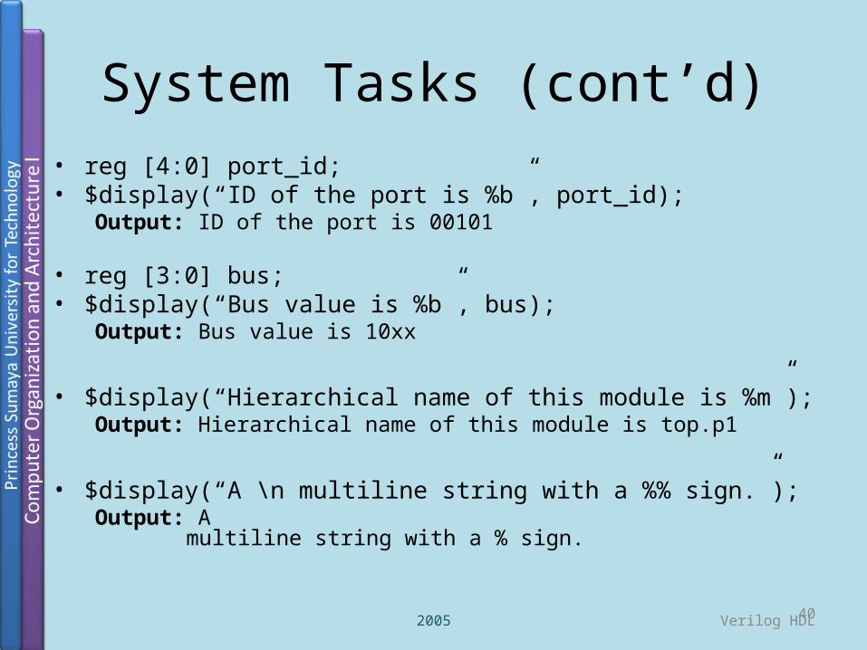
System Tasks (cont’d)• reg [4:0] port_id;• $display(“ID of the port is %b”, port_id);
Output: ID of the port is 00101
• reg [3:0] bus;• $display(“Bus value is %b”, bus);
Output: Bus value is 10xx
• $display(“Hierarchical name of this module is %m”);
Output: Hierarchical name of this module is top.p1
• $display(“A \n multiline string with a %% sign.”);Output: A
multiline string with a % sign.

2005 Verilog HDL41
System Tasks (cont’d)• $monitor: monitors a signal when its value changes• Syntax: $monitor(p1, p2, p3, …, pn);
p1,…, pn can be quoted string, variable, or signal namesFormat specifiers just as $displayContinuously monitors the values of the specified variables or
signals, and displays the entire list whenever any of them changes.
$monitor needs to be invoked only once (unlike $display) Only one $monitor (the latest one) can be active at any time$monitoroff to temporarily turn off monitoring$monitoron to turn monitoring on again

2005 Verilog HDL42
System Tasks (cont’d)• $monitor Examples:
initial
begin
$monitor($time, “Value of signals clock=%b, reset=%b”, clock, reset);
end
Output:0 value of signals clock=0, reset=15 value of signals clock=1, reset=110 value of signals clock=0, reset=0
2005 Verilog HDL43
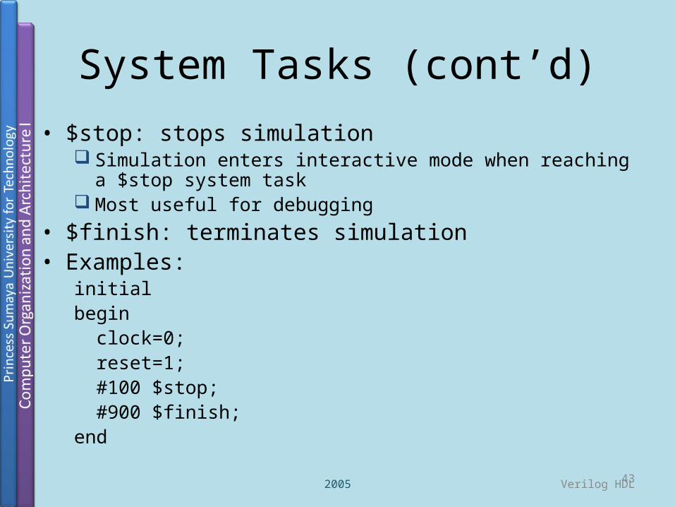
System Tasks (cont’d)• $stop: stops simulation
Simulation enters interactive mode when reaching a $stop system task
Most useful for debugging• $finish: terminates simulation• Examples:
initial begin clock=0; reset=1; #100 $stop; #900 $finish;end
2005 Verilog HDL44
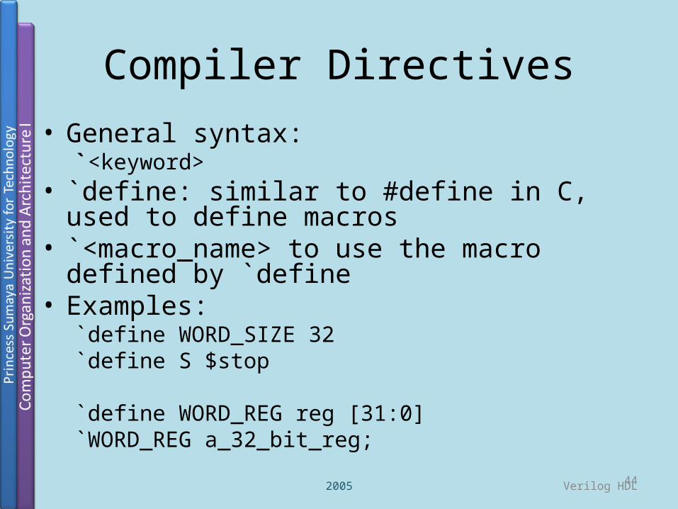
Compiler Directives• General syntax:
`<keyword>• `define: similar to #define in C, used to define
macros• `<macro_name> to use the macro defined by `define
• Examples:`define WORD_SIZE 32`define S $stop
`define WORD_REG reg [31:0]`WORD_REG a_32_bit_reg;

2005 Verilog HDL45
Compiler Directives (cont’d)
• `include: Similar to #include in C, includes entire contents of another file in your Verilog source file
• Example:`include header.v
...
<Verilog code in file design.v>
...

Behavior Modeling

simpleBehavioral.v
module aOrNotbOrc(d, a, b, c); output d; input a, b, c; reg d, p;
always @(a or b or c) begin p = a || ~b; d = p || c; endendmodule
Modules are of three types: behavioral, dataflow, gate-level. Behavioral modules contain code in procedural blocks.
Statements in a procedural block cannot be re-ordered without affecting the program asthese statements are executed sequentially,exactly like in a conventional programming language such as C.
Ports are of three types: input, output, inout.Each must be declared. Each port also has a data type: either reg or wire (net). Default is wire.Inputs and inouts are always wire. Output ports that hold their value are reg, otherwise wire. More later…
One port register, one internal register.
Sensitivity trigger: when any of a, b or c changes.Replace this statement with “initial”. Output?!
Wires are part of the more general class of nets. However, the only nets we shall design with are wires.
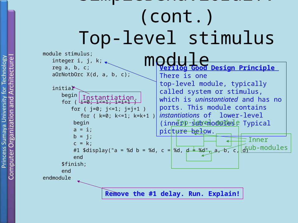
simpleBehavioral.v (cont.)Top-level stimulus module
module stimulus; integer i, j, k; reg a, b, c; aOrNotbOrc X(d, a, b, c);
initial begin for ( i=0; i<=1; i=i+1 ) for ( j=0; j<=1; j=j+1 ) for ( k=0; k<=1; k=k+1 )
begin a = i; b = j; c = k; #1 $display("a = %d b = %d, c = %d, d = %d", a, b, c, d) end
$finish; endendmodule
Verilog Good Design Principle There is one top-level module, typically called system or stimulus, which is uninstantiated and has no ports. This module contains instantiations of lower-level (inner) sub-modules. Typical picture below.
Remove the #1 delay. Run. Explain!
Top-level module
Innersub-modules
Instantiation.

reg or wire
Port Rules Diagram
input output
wirereg or wire wire
inoutwire
wire
EXTERNALMODULE
Internal ports
INTERNALMODULE
Outside connectorsto internal ports, i.e., variables correspondingto ports in instantiationof internal module
Example:module externalreg a;wire b;internal in(a, b); //instantiation…endmodule
module internal(x, y)input x;output y;wire x;reg y;…endmodule
port
-con
nect
or
General rule (with few exceptions) Ports in all modules except for thestimulus module should be wire. Stimulus module has registers to set data for internal modules and wire ports only to read data from internal modules.

If StatementsSyntax
if (expression) begin ...statements... end else if (expression) begin ...statements... end ...more else if blocks
else begin ...statements... end
Dr. Esam Al-Qaralleh 50

Case StatementsSyntax
case (expression) case_choice1: begin ...statements... end
case_choice2: begin ...statements... end
...more case choices blocks...
default: begin ...statements... endendcase
Dr. Esam Al-Qaralleh 51

For loops
Syntax
for (count= value1; count</<=/>/>= value2; count=count+/- step)begin ...statements...end
integer j;
for(j=0;j<=7;j=j+1)begin c[j] = a[j] + b[j];end
Dr. Esam Al-Qaralleh 52
Component Inference

Flip-Flops
always@(posedge clk)begin a<=b;end
CB
Dr. Esam Al-Qaralleh 54
a<=b&c;
Q
D
CLKclk
A
B
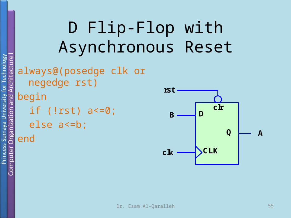
D Flip-Flop with Asynchronous Reset
always@(posedge clk or negedge rst)begin if (!rst) a<=0; else a<=b;end
Q
D
CLKclk
A
B
rst
clr
Dr. Esam Al-Qaralleh 55

D Flip-flop with Synchronous reset and Enable
always@(posedge clk)begin if (rst) a<=0; else if (enable) a<=b;end Q
D
CLKclk
Aenable EN
rstB
Dr. Esam Al-Qaralleh 56

Shift Registers
reg[3:0] Q;always@(posedge clk or
posedge rset )begin if (rset) Q<=0; else begin Q <=Q << 1; Q[0]<=Q[3]; end
QD
CLK
QD
CLK
QD
CLK
QD
CLK
clk
Dr. Esam Al-Qaralleh 57
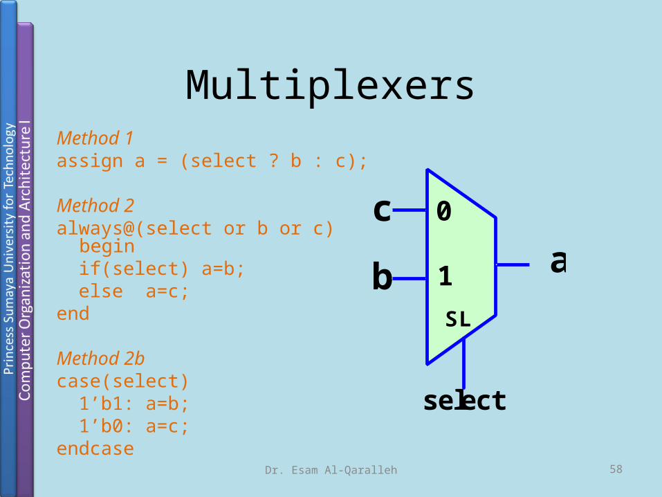
MultiplexersMethod 1assign a = (select ? b : c);
Method 2always@(select or b or c) begin if(select) a=b; else a=c;end
Method 2bcase(select) 1’b1: a=b; 1’b0: a=c;endcase
b
c
a
SL
0
1
select
Dr. Esam Al-Qaralleh 58

Counters
reg [7:0] count;wire enable;always@(posedge clk or negedge rst)begin if (rst) count<=0; else if (enable)
count<=count+1;end
count
clr
EN
rst
enable
Dr. Esam Al-Qaralleh 59
Step by Step 4-bit adder

• Step 1: build a 1-bit full adder as a moduleS = (a) XOR (b) XOR (Cin ) ; ( S = a^b^Cin)
Cout = (a&b) |(Cin&(a+b))
4-bit Adder
Dr. Esam Al-Qaralleh 61
module FA_1bit (S,Cout,a,b,Cin);begin input a,b,Cin;Output S, Cout;
assign Sum = a^b^Cin;assign Carry = (a&b) | (Cin&(a^b));
endmodule
Module add_1bit

• Step 2: initiate 4 instances of FA_1bit module4-bit Adder
Dr. Esam Al-Qaralleh 62
1-bit Full
Adder
A0B0
Cin
S0
1-bit Full
Adder
A1B1
S1
1-bit Full
Adder
A2B2
S2
1-bit Full
Adder
A3B3
S3
Cout
The inputs and the output are 4-bits wideThe inputs and the output are 4-bits wide
module FA_4bits (S,Cout,A,B,Cin);begin
input [3:0] A, B;input Cin;output [3:0] S;output Coutwire Cout0, Cout1, Cout2
FA_1bit FA1(S[0], Cout0,A[0],B[0],Cin);FA_1bit FA1(S[1], Cout1,A[1],B[1],Cout0);FA_1bit FA1(S[2], Cout2,A[2],B[2],Cout1);FA_1bit FA1(S[3], Cout,A[3],B[3],Cout2);endendmodule;
module FA_4bits (S,Cout,A,B,Cin);begin
input [3:0] A, B;input Cin;output [3:0] S;output Coutwire Cout0, Cout1, Cout2
FA_1bit FA1(S[0], Cout0,A[0],B[0],Cin);FA_1bit FA1(S[1], Cout1,A[1],B[1],Cout0);FA_1bit FA1(S[2], Cout2,A[2],B[2],Cout1);FA_1bit FA1(S[3], Cout,A[3],B[3],Cout2);endendmodule;
Cout0Cout1Cout2
we need wires to propagate the carry from one stage to the next
we need wires to propagate the carry from one stage to the next
you may name the instances with any name, but you have to maintain the order of the inputs and outputs
you may name the instances with any name, but you have to maintain the order of the inputs and outputs
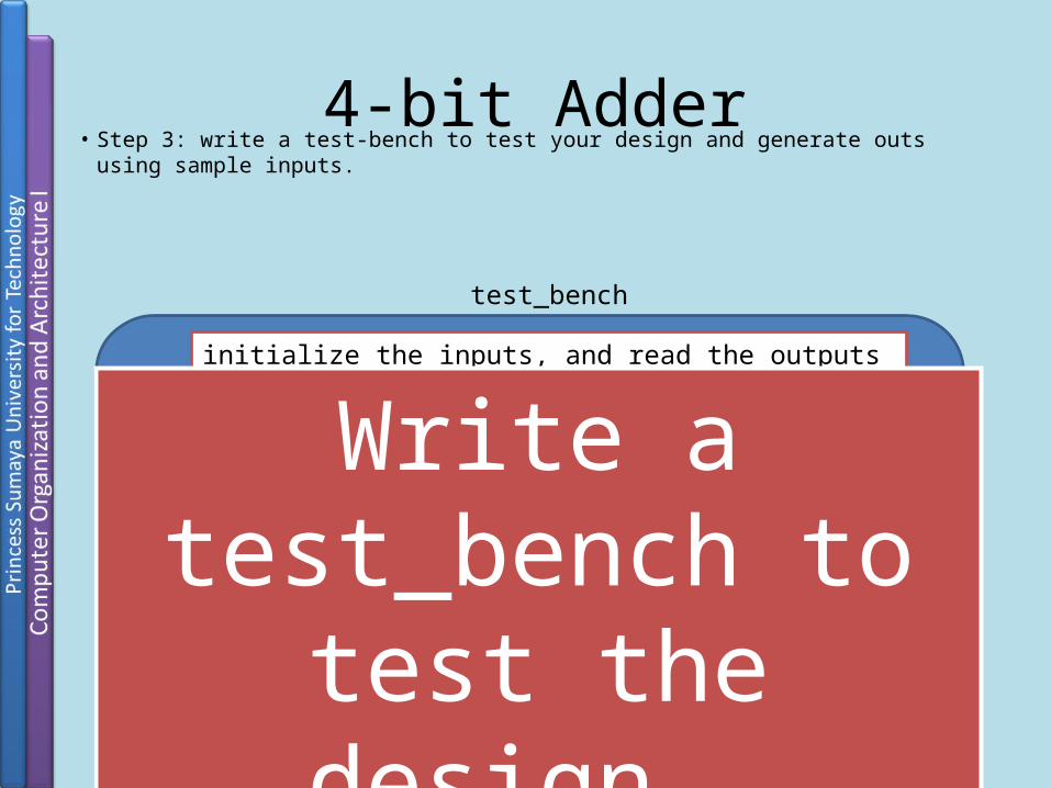
• Step 3: write a test-bench to test your design and generate outs using sample inputs. 4-bit Adder
4-bits Full Adder
4-bits Full Adder
A[3:0]
B[3:0]
Cin
S[3:0]
Cout
4
4
4
initialize the inputs, and read the outputs
test_bench
Write a test_bench to test the design.
Write a test_bench to test the design.

modulemodule test_bench; // you may name it by any name//define the variables you will use in the designregreg [3:0] A,B,S;reg reg Cin, Cout// Create an instance from the full adderFA_4bits FA(S[3:0],Cout, A[3:0], B[3:0], Cin);//initialize the variables once initialinitialA = 5; B = 6; S = 0; Cin = 0; Cout = 0;initialinitialbeginbegin$display$display(“A=%d, B=%d, the sum = %d, and the carry = %d”, A,B,S,Cout)$finish$finishendendendmoduleendmodule
4-bit Adder

modulemodule test_bench; // you may name it by any name//define the variables you will use in the designregreg [3:0] A,B,S;integerinteger I,j;reg reg Cin, Cout// Create an instance from the full adderFA_4bits FA(S,Cout, A, B, Cin);//initialize the variables once initial begininitial begin $monitor $monitor ("A: %d B: %d sum: %d carry: %d", A, B, sum, carry); for (i=0; i<16; i=i+1) for (j=0; j<16; j=j+1) beginbegin A = i; B = j; #1 ; endend $finish$finish; endendendmoduleendmodule
4-bit Adder
System calls.

More Examples
blocksTime1.v
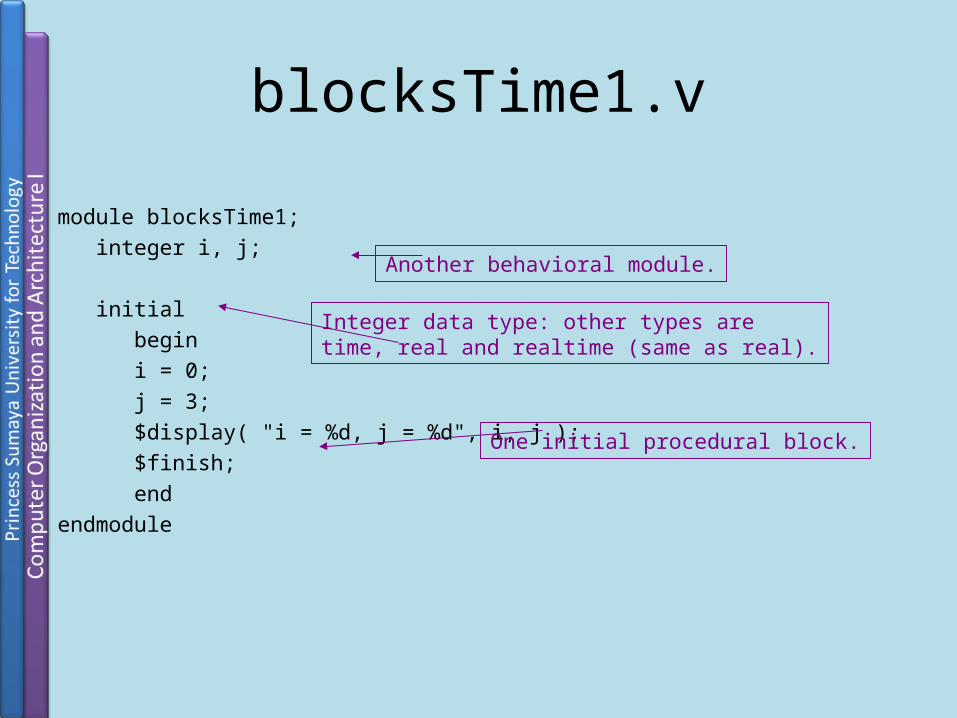
module blocksTime1; integer i, j;
initial begin i = 0; j = 3; $display( "i = %d, j = %d", i, j ); $finish; endendmodule
One initial procedural block.
Another behavioral module.
Integer data type: other types aretime, real and realtime (same as real).
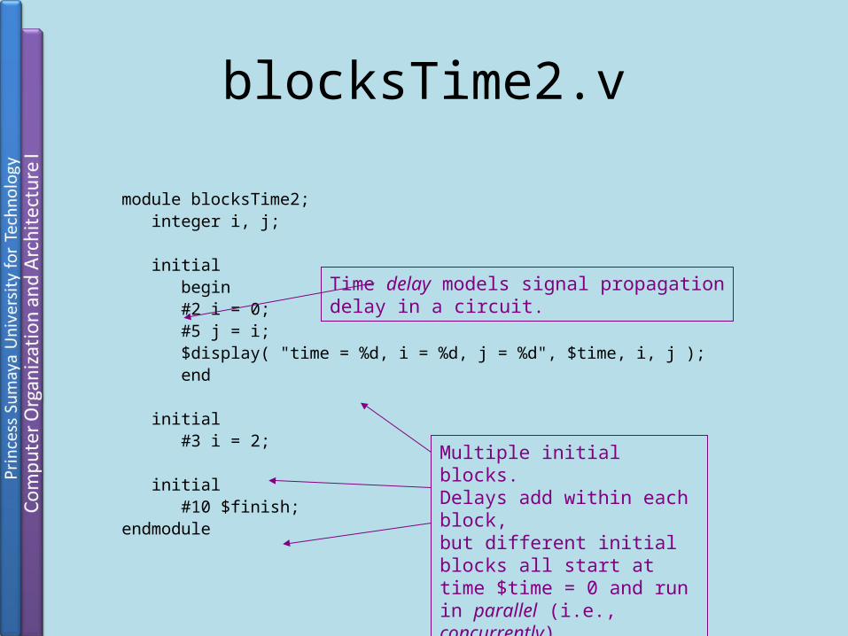
blocksTime2.v
module blocksTime2; integer i, j;
initial begin #2 i = 0; #5 j = i; $display( "time = %d, i = %d, j = %d", $time, i, j ); end
initial #3 i = 2;
initial #10 $finish;endmodule
Multiple initial blocks.Delays add within each block, but different initial blocks all start at time $time = 0 and run in parallel (i.e., concurrently).
Time delay models signal propagationdelay in a circuit.

blocksTime3.vmodule blocksTime3; integer i, j;
initial begin #2 i = 0; #5 j = i; $display( "time = %d, i = %d, j = %d", $time, i, j ); end
initial begin #3 i = 2; #2 j = i; $display( "time = %d, i = %d, j = %d", $time, i, j ); #1 j = 8; $display( "time = %d, i = %d, j = %d", $time, i, j ); end
initial #10 $finish;endmodule Multiple initial blocks.
Predict output before you run!
Important Verilog is a discrete event simulator:events are executed in a time-ordered queue.

blocksTime4.vmodule blocksTime4; integer i, j;
initial begin i = 0; j = 3; end
initial #10 $finish;
always begin #1 i = i + 1; j = j + 1; $display( "i = %d, j = %d", i, j ); endendmodule
Always block is an infinite loop. Following are same:
always initial initial begin begin begin … while(1) forever end begin begin … … end end end end
Comment out this delay.Run. Explain the problem!

module clockGenerator(clk); output clk; reg clk;
initial begin clk = 0; end
always #5 clk = ~clk;endmodule
The delay is half the clock period.
If this module is run stand-alone makesure to add a $finish statement here or simulation will never complete!
Internal register.
Register reg data type can have one offour values: 0, 1, x, z. Registers store avalue till the next assignment. Registersare assigned values in procedural blocks.
clockGenerator.vPort list. Ports can be of three types: input,output, inout. Each must be declared.

useClock.v
module useClock(clk); input clk; clockGenerator cg(clk); initial #50 $finish;
always @(posedge clk) $display("Time = %d, Clock up!", $time);
always @(negedge clk) // $display("Time = %d, Clock down!", $time);endmodule
Compile with the clockGenerator.v module.
Event trigger.
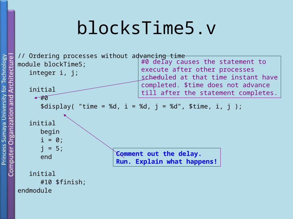
// Ordering processes without advancing timemodule blockTime5; integer i, j;
initial #0 $display( "time = %d, i = %d, j = %d", $time, i, j );
initial begin i = 0; j = 5; end
initial #10 $finish;endmodule
blocksTime5.v
#0 delay causes the statement toexecute after other processes scheduled at that time instant havecompleted. $time does not advancetill after the statement completes.
Comment out the delay.Run. Explain what happens!

module blocksTime6; integer i, j;
initial begin #2 i = 0; j = #5 i; $display( "time = %d, i = %d, j = %d", $time, i, j ); end
initial #3 i = 2;
initial #10 $finish;endmodule
blocksTime6.v
Intra-assignment delay: RHS is computed andstored in a temporary (transparent to user) and LHS is assigned the temporary after the delay.
Compare output with blocksTime2.v.
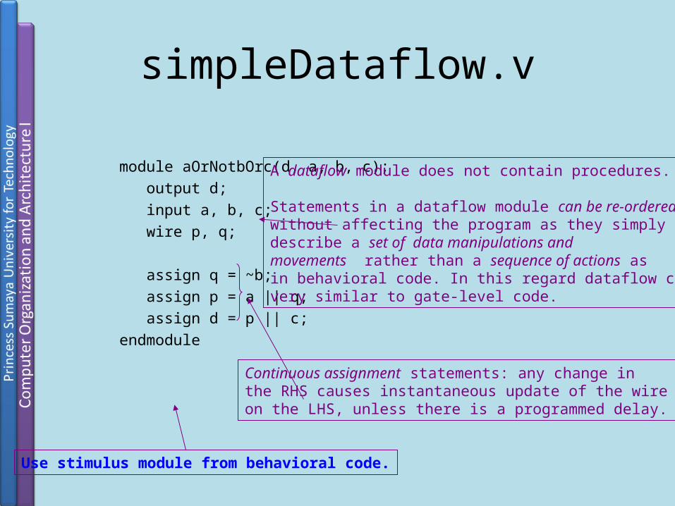
simpleDataflow.v
module aOrNotbOrc(d, a, b, c); output d; input a, b, c; wire p, q;
assign q = ~b; assign p = a || q; assign d = p || c;endmodule
Continuous assignment statements: any change inthe RHS causes instantaneous update of the wire on the LHS, unless there is a programmed delay.
A dataflow module does not contain procedures.
Statements in a dataflow module can be re-orderedwithout affecting the program as they simply describe a set of data manipulations and movements rather than a sequence of actions as in behavioral code. In this regard dataflow code isvery similar to gate-level code.
Use stimulus module from behavioral code.

simpleGate.v
module aOrNotbOrc(d, a, b, c); output d; input a, b, c; wire p, q;
not(q, b); or(p, a, q); or(d, p, c);endmodule
Primitive gates. Verilog providesseveral such, e.g., and, or, nand, nor, not, buf, etc.
A gate-level module does not contain procedures.
Statements in a gate-level module can be re-orderedwithout affecting the program as they simply describe a set of connections rather than a sequenceof actions as in behavioral code. A gate-levelmodule is equivalent to a combinational circuit.
Wire data type can have one of four values: 0, 1, x, z.Wires cannot store values – they are continuouslydriven.
Use stimulus module from behavioral code.
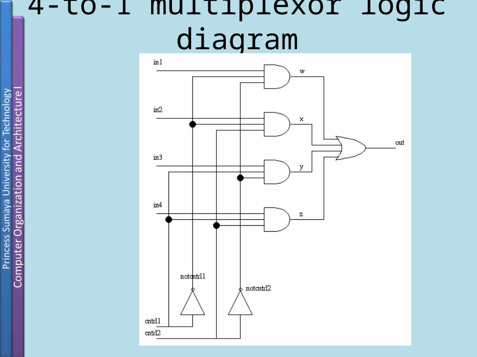
4-to-1 multiplexor logic diagram

4-to-1 multiplexor (Folder Multiplexor)
Following are four different Verilog implementations of the same multiplexor.A stimulus module is shared to test each implementation.

multiplexor4_1Gate.v
module multiplexor4_1(out, in1, in2, in3, in4, cntrl1, cntrl2);output out;
input in1, in2, in3, in4, cntrl1, cntrl2;wire notcntlr1, notcntrl2, w, x, y, z;
not (notcntrl1, cntrl1); not (notcntrl2, cntrl2);
and (w, in1, notcntrl1, notcntrl2); and (x, in2, notcntrl1, cntrl2); and (y, in3, cntrl1, notcntrl2); and (z, in4, cntrl1, cntrl2);
or (out, w, x, y, z);endmodule
Structural gate-level code basedexactly on the logic diagram.
Recall default type is wire.

multiplexor4_1Stimulus.v(Folder Multiplexor)
module muxstimulus;reg IN1, IN2, IN3, IN4, CNTRL1, CNTRL2;
wire OUT;
multiplexor4_1 mux1_4(OUT, IN1, IN2, IN3, IN4, CNTRL1, CNTRL2);
initial begin
IN1 = 1; IN2 = 0; IN3 = 1; IN4 = 0; $display("Initial arbitrary values"); #0 $display("input1 = %b, input2 = %b, input3 = %b, input4 = %b\n", IN1, IN2, IN3, IN4);
{CNTRL1, CNTRL2} = 2'b00; #1 $display("cntrl1=%b, cntrl2=%b, output is %b", CNTRL1, CNTRL2, OUT);Concatenation.
Stimulus code that generatestest vectors.
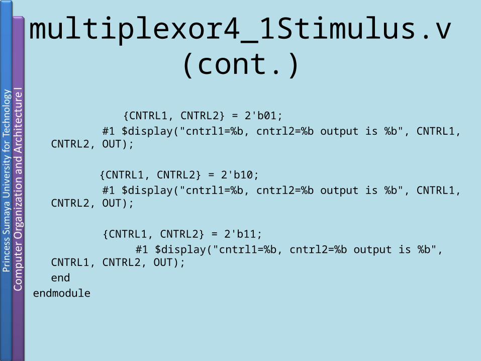
multiplexor4_1Stimulus.v (cont.)
{CNTRL1, CNTRL2} = 2'b01; #1 $display("cntrl1=%b, cntrl2=%b output is %b", CNTRL1, CNTRL2, OUT);
{CNTRL1, CNTRL2} = 2'b10; #1 $display("cntrl1=%b, cntrl2=%b output is %b", CNTRL1, CNTRL2, OUT);
{CNTRL1, CNTRL2} = 2'b11; #1 $display("cntrl1=%b, cntrl2=%b output is %b", CNTRL1, CNTRL2, OUT);
endendmodule
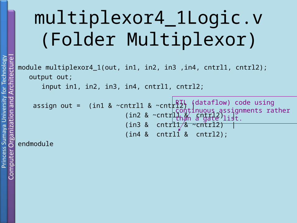
multiplexor4_1Logic.v(Folder Multiplexor)
module multiplexor4_1(out, in1, in2, in3 ,in4, cntrl1, cntrl2);output out;
input in1, in2, in3, in4, cntrl1, cntrl2;
assign out = (in1 & ~cntrl1 & ~cntrl2) | (in2 & ~cntrl1 & cntrl2) | (in3 & cntrl1 & ~cntrl2) | (in4 & cntrl1 & cntrl2);endmodule
RTL (dataflow) code using continuous assignments rather than a gate list.

multiplexor4_1Conditional.v(Folder Multiplexor)
module multiplexor4_1(out, in1, in2, in3, in4, cntrl1, cntrl2);output out;input in1, in2, in3, in4, cntrl1, cntrl2;
assign out = cntrl1 ? (cntrl2 ? in4 : in3) : (cntrl2 ? in2 : in1);endmodule
More RTL (dataflow) code – this time using conditionals in a continuous assignment.

multiplexor4_1Case.v(Folder Multiplexor)
module multiplexor4_1(out, in1, in2, in3, in4, cntrl1, cntrl2); output out;
input in1, in2, in3, in4, cntrl1, cntrl2; reg out;
always @(in1 or in2 or in3 or in4 or cntrl1 or cntrl2) case ({cntrl1, cntrl2})
2'b00 : out = in1; 2'b01 : out = in2; 2'b10 : out = in3; 2'b11 : out = in4; default : $display("Please check control bits"); endcaseendmodule
Behavioral code: output out must now be of reg type as it is assigned values in a procedural block.

8-to-3 encoder truth table
Input OutputD7 D6 D5 D4 D3 D2 D1 D0 A2 A1 A0 0 0 0 0 0 0 0 1 0 0 0
0 0 0 0 0 0 1 0 0 0 1
0 0 0 0 0 1 0 0 0 1 0
0 0 0 0 1 0 0 0 0 1 1
0 0 0 1 0 0 0 0 1 0 0
0 0 1 0 0 0 0 0 1 0 1
0 1 0 0 0 0 0 0 1 1 0
1 0 0 0 0 0 0 0 1 1 1

8-to-3 encoder (Folder Encoder)Following are four different Verilog implementations of the same encoder.Each has its own stimulus module.

encoder8_3Behavioral.vmodule encoder8_3( encoder_out , enable, encoder_in );
output[2:0] encoder_out; input enable; input[7:0] encoder_in; reg[2:0] encoder_out;always @ (enable or encoder_in)begin
if (enable)case ( encoder_in )
8'b00000001 : encoder_out = 3'b000;8'b00000010 : encoder_out = 3'b001;8'b00000100 : encoder_out = 3'b010;8'b00001000 : encoder_out = 3'b011;8'b00010000 : encoder_out = 3'b100;8'b00100000 : encoder_out = 3'b101;8'b01000000 : encoder_out = 3'b110;8'b10000000 : encoder_out = 3'b111;default : $display("Check input bits.");
endcaseend
endmodule
Simple behavioral code using the case statement.
Sensitivity list.

encoder8_3BehavioralStimulus.v
module stimulus;wire[2:0] encoder_out;reg enable;reg[7:0] encoder_in;encoder8_3 enc( encoder_out, enable, encoder_in );initial begin
enable = 1; encoder_in = 8'b00000010;#1 $display("enable = %b, encoder_in = %b, encoder_out = %b", enable, encoder_in, encoder_out);#1 enable = 0; encoder_in = 8'b00000001;#1 $display("enable = %b, encoder_in = %b, encoder_out = %b",
enable, encoder_in, encoder_out);#1 enable = 1; encoder_in = 8'b00000001;#1 $display("enable = %b, encoder_in = %b, encoder_out = %b",
enable, encoder_in, encoder_out);#1 $finish;
endendmodule
Remove this delay.Run. Explain!
Stimulus for the behavioral code.
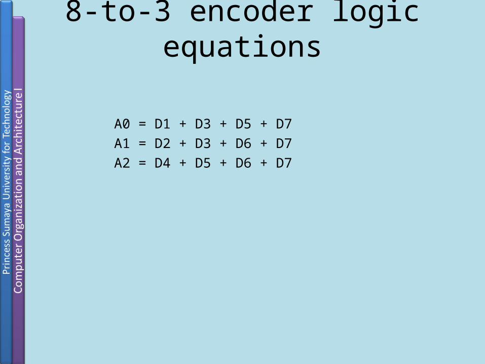
8-to-3 encoder logic equations
A0 = D1 + D3 + D5 + D7
A1 = D2 + D3 + D6 + D7
A2 = D4 + D5 + D6 + D7

encoder8_3structural.v(Folder Encoder)
module encoder8_3( encoder_out , encoder_in );output[2:0] encoder_out; input[7:0] encoder_in;
or( encoder_out[0], encoder_in[1], encoder_in[3], encoder_in[5], encoder_in[7] );or( encoder_out[1], encoder_in[2], encoder_in[3], encoder_in[6], encoder_in[7] );or( encoder_out[2], encoder_in[4], encoder_in[5], encoder_in[6], encoder_in[7] );
endmodule
Structural code. Why is there no enable wire?! Hint: think storage.
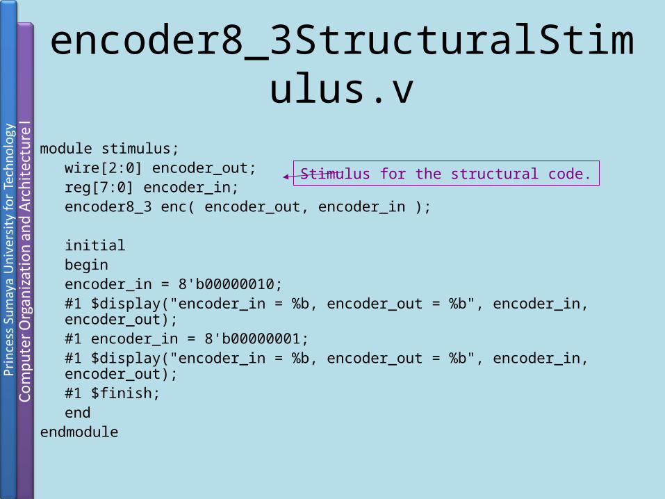
encoder8_3StructuralStimulus.v
module stimulus;wire[2:0] encoder_out;reg[7:0] encoder_in;encoder8_3 enc( encoder_out, encoder_in );
initial begin
encoder_in = 8'b00000010;#1 $display("encoder_in = %b, encoder_out = %b", encoder_in, encoder_out);#1 encoder_in = 8'b00000001;#1 $display("encoder_in = %b, encoder_out = %b", encoder_in, encoder_out);#1 $finish;
endendmodule
Stimulus for the structural code.

encoder8_3Mixed.vmodule encoder8_3( encoder_out , enable, encoder_in );
output[2:0] encoder_out;input enable; input[7:0] encoder_in; reg[2:0] encoder_out;wire b0, b1, b2;
or( b0, encoder_in[1], encoder_in[3], encoder_in[5], encoder_in[7] );or( b1, encoder_in[2], encoder_in[3], encoder_in[6], encoder_in[7] );or( b2, encoder_in[4], encoder_in[5], encoder_in[6], encoder_in[7] );
always @(enable or encoder_in)beginif (enable) encoder_out = {b2, b1, b0};end
endmodule
Mixed structural-behavioral code. Goal wasto modify structural code to have an enablewire, which requires register output for storage.
Be careful with mixed design! It’s working may be difficult to understand.

encoder8_3MixedStimulus.vmodule stimulus;
wire[2:0] encoder_out;reg enable;reg[7:0] encoder_in;encoder8_3 enc( encoder_out, enable, encoder_in );
initial begin
enable = 1; encoder_in = 8'b00000010;#1 $display("enable = %b, encoder_in = %b, encoder_out = %b",
enable, encoder_in, encoder_out);
#1 enable = 1; encoder_in = 8'b00000010;#1 $display("enable = %b, encoder_in = %b, encoder_out = %b", enable, encoder_in, encoder_out);
Stimulus for the mixed code.
Output is puzzling! Explain!
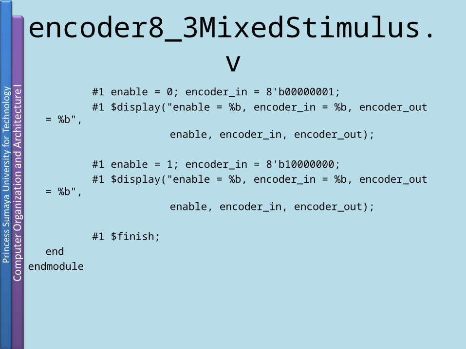
#1 enable = 0; encoder_in = 8'b00000001;#1 $display("enable = %b, encoder_in = %b, encoder_out = %b",
enable, encoder_in, encoder_out);
#1 enable = 1; encoder_in = 8'b10000000;#1 $display("enable = %b, encoder_in = %b, encoder_out = %b",
enable, encoder_in, encoder_out);
#1 $finish;end
endmodule
encoder8_3MixedStimulus.v

Comparator modules scheme
comparator.v
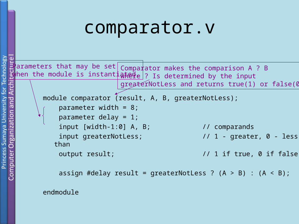
module comparator (result, A, B, greaterNotLess); parameter width = 8; parameter delay = 1; input [width-1:0] A, B; // comparands input greaterNotLess; // 1 - greater, 0 - less than output result; // 1 if true, 0 if false assign #delay result = greaterNotLess ? (A > B) : (A < B); endmodule
Comparator makes the comparison A ? Bwhere ? Is determined by the inputgreaterNotLess and returns true(1) or false(0).
Parameters that may be setwhen the module is instantiated.

stimulus.v
module system; wire greaterNotLess; // sense of comparison wire [15:0] A, B; // comparand values - 16 bit wire result; // comparison result // Module instances comparator #(16, 2) comp (result, A, B, greaterNotLess); testGenerator tg (A, B, greaterNotLess, result);
endmodule
Stimulus for the comparator.
Parameters being set at module instantiation.
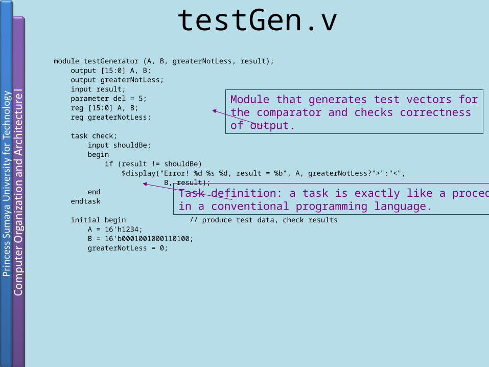
testGen.vmodule testGenerator (A, B, greaterNotLess, result); output [15:0] A, B; output greaterNotLess; input result; parameter del = 5; reg [15:0] A, B; reg greaterNotLess; task check; input shouldBe; begin if (result != shouldBe) $display("Error! %d %s %d, result = %b", A, greaterNotLess?">":"<", B, result); end endtask initial begin // produce test data, check results A = 16'h1234; B = 16'b0001001000110100; greaterNotLess = 0;
Module that generates test vectors forthe comparator and checks correctnessof output.
Task definition: a task is exactly like a procedurein a conventional programming language.

testGen.v (cont.)#del check(0); B = 0; greaterNotLess = 1; #del check(1); A = 1; greaterNotLess = 0; #del check(0); $finish; endendmodule
Task call
Finite State Machines

Standard Form for a Verilog FSM
// state flip-flopsreg [2:0] state, nxt_st;// state definitionsparameter reset=0,S1=1,S2=2,S3=3,..
// NEXT STATE CALCULATIONSalways@(state or inputs or ...)begin … next_state= ... …end
// REGISTER DEFINITIONalways@(posedge clk)begin state<=next_state;end
// OUTPUT CALCULATIONSoutput= f(state, inputs)
Dr. Esam Al-Qaralleh 101

Examplemodule myFSM (clk, x, z)input clk, x; output z;// state flip-flopsreg [2:0] state, nxt_st;// state definitionparameter
S0=0,S1=1,S2=2,S3=3,S7=7
// REGISTER DEFINITIONalways @(posedge clk) begin state<=nxt_st;end
// OUTPUTCALCULATIONSassign z = (state==S7);
// NEXT STATE CALCULATIONSalways @(state or x)begincase (state) S0: if(x) nxt_st=S1; else nxt_st=S0; S1: if(x) nxt_st=S3; else nxt_st=S2; S2: if(x) nxt_st=S0; else nxt_st=S7; S3: if(x) nxt_st=S2; else nxt_st=S7; S7: nxt_st=S0; default: nxt_st = S0;endcaseend
endmodule
Dr. Esam Al-Qaralleh 102

0111 Sequence Detector
S0z=0
S1z=0
S2z=0
S4z=1
S3z=0
1
0
1
1
1
1
0
00
0
Dr. Esam Al-Qaralleh 103

Test Benches
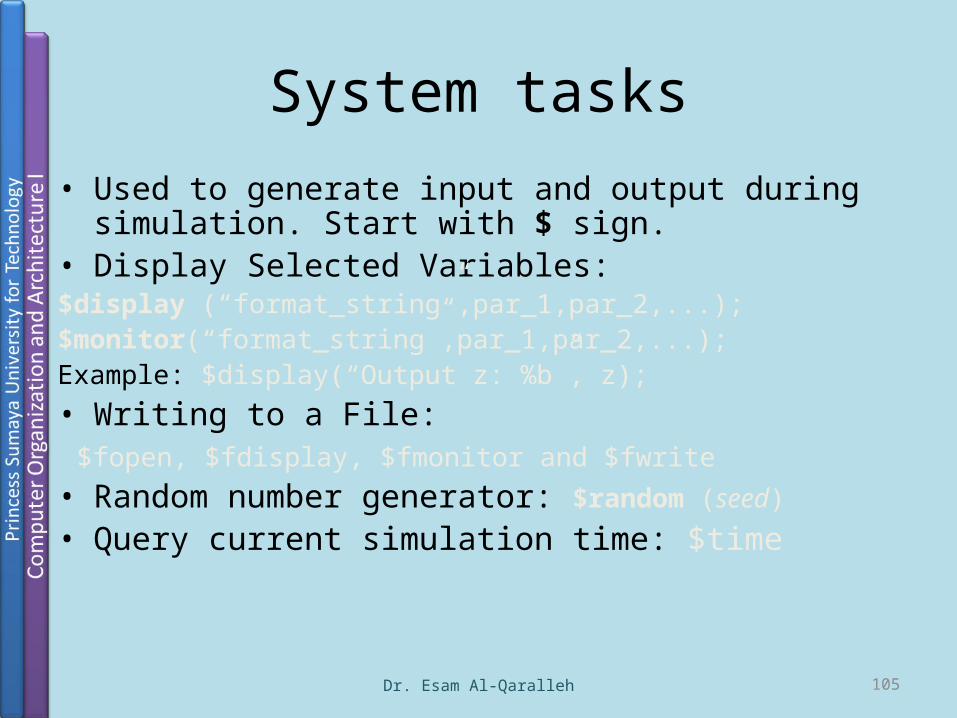
System tasks• Used to generate input and output during simulation. Start
with $ sign.• Display Selected Variables:$display (“format_string”,par_1,par_2,...);$monitor(“format_string”,par_1,par_2,...);Example: $display(“Output z: %b”, z);• Writing to a File: $fopen, $fdisplay, $fmonitor and $fwrite• Random number generator: $random (seed)
• Query current simulation time: $time
Dr. Esam Al-Qaralleh 105
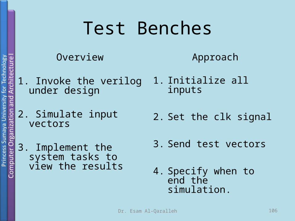
Test BenchesOverview
1. Invoke the verilog under design
2. Simulate input vectors
3. Implement the system tasks to view the results
Approach
1. Initialize all inputs
2. Set the clk signal
3. Send test vectors
4. Specify when to end the simulation.
Dr. Esam Al-Qaralleh 106

Example‘timescale1 ns /100 ps // timeunit =1ns; precision=1/10ns;module my_fsm_tb; reg clk, rst, x;wire z;
/**** DESIGN TO SIMULATE (my_fsm) INSTANTIATION ****/
myfsm dut1(clk, rst, x, z);
/****RESET AND CLOCK SECTION****/Initial beginclk=0; rst=0;#1rst=1; /*The delay gives rst a posedge for sure.*/#200 rst=0; //Deactivate reset after two clock cycles
+1ns*/endalways #50clk=~clk; /* 10MHz clock (50*1ns*2) with
50% duty-cycle */
/****SPECIFY THE INPUT WAVEFORM x ****/Initial begin #1 x=0; #400 x=1; $display(“Output z: %b”, z); #100 x=0; @(posedge clk) x=1; #1000 $finish; //stop simulation //without this, it will not stopendendmodule
Dr. Esam Al-Qaralleh 107

Modelsim Demonstration