precision machine design · pdf fileminimize cost. t mechanical system ... through the...
TRANSCRIPT

© 1994 by Alexander H. Slocum
2-1
Precision Machine Design
Topic 2
Assessment of errors in precision machines
Purpose:
This lecture defines types of errors and discusses methods formodeling them and accounting for them (error budgets) whenpredicting machine performance.
Outline:
• I ntroduction
• Definitions
• Homogeneous transformation matrices
• Introduction to error budgets
• Error types
"Mathematics is the language with which God has written theuniverse"
Galileo
© 1994 by Alexander H. Slocum
2-2
Introduction
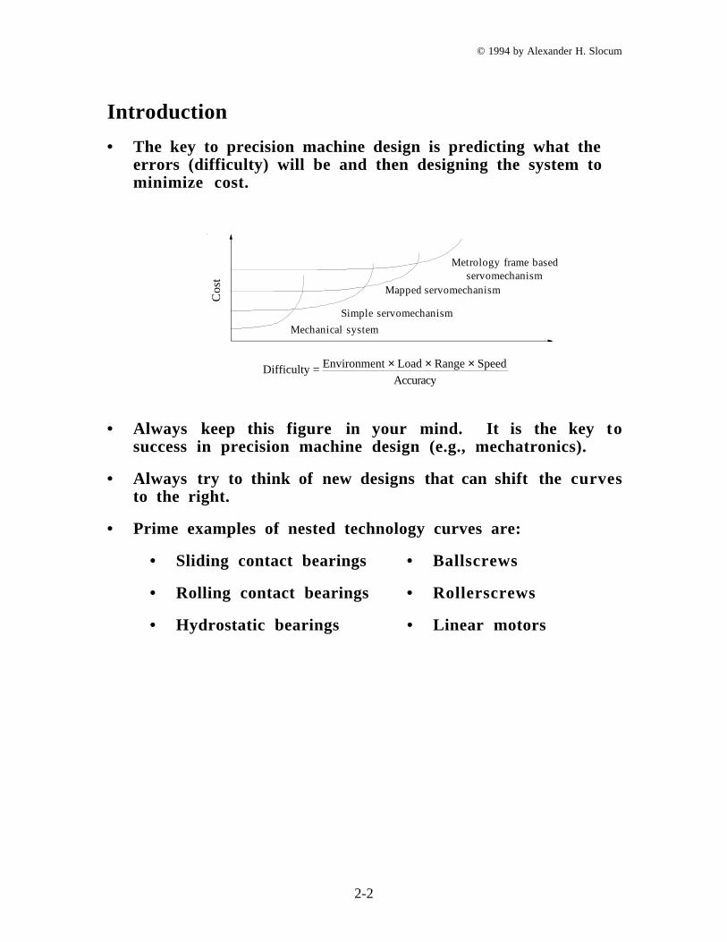
• The key to precision machine design is predicting what theerrors (difficulty) will be and then designing the system tominimize cost.
Co
st
Mechanical system
Simple servomechanism
Mapped servomechanism
Metrology frame based servomechanism
Difficulty = Environment × Load × Range × Speed
Accuracy
• Always keep this figure in your mind. It is the key tosuccess in precision machine design (e.g., mechatronics).
• Always try to think of new designs that can shift the curvesto the right.
• Prime examples of nested technology curves are:
• Sliding contact bearings • Ballscrews
• Rolling contact bearings • Rollerscrews
• Hydrostatic bearings • Linear motors
© 1994 by Alexander H. Slocum
2-3
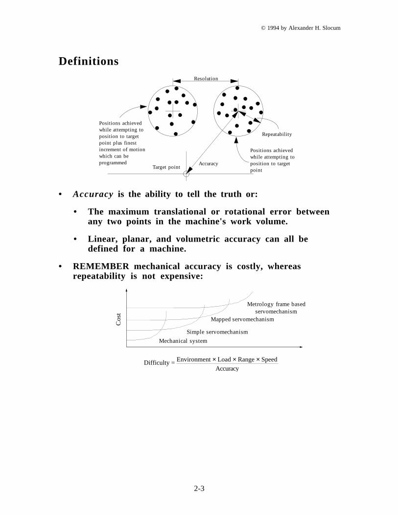
DefinitionsResolution
Repeatability
Target point
Positions achieved while attempting toposition to target point
Accuracy
Positions achievedwhile attempting toposition to target point plus finestincrement of motionwhich can be programmed
• Accuracy is the ability to tell the truth or:
• The maximum translational or rotational error betweenany two points in the machine's work volume.
• Linear, planar, and volumetric accuracy can all bedefined for a machine.
• REMEMBER mechanical accuracy is costly, whereasrepeatability is not expensive:
Co
st
Mechanical system
Simple servomechanism
Mapped servomechanism
Metrology frame based servomechanism
Difficulty = Environment × Load × Range × Speed
Accuracy
© 1994 by Alexander H. Slocum
2-4
• Repeatability (precision) is the ability to tell the same storyover and over again or:
• The error between a number of successive attempts tomove the machine to the same position.
• Repeatability is often considered to be the most importantparameter of a computer controlled machine (or sensor)
• Often the intent is to map the errors and thencompensate for them.
• Minimize static friction and thermal variants to get betterrepeatability.
• Resolution is how detailed your story is.
• Resolution is the larger of the smallest programmablestep or:
• The smallest mechanical step the machine can makeduring point to point motion.
• Resolution gives a lower bound on the repeatability.
• Minimize static friction to get better resolution.

© 1994 by Alexander H. Slocum
2-5
Abbe Errors
"If errors in parallax are to be avoided, the measuring systemmust be placed coaxially with the axis along which displacementis to be measured on the workpiece" . Dr. Ernst Abbe
• Perhaps the greatest design sin is amplifying an angularerror by a lever arm. This is known as an Abbe error:
• Abbe error illustrated through the use of a dial caliper and amicrometer.
������
Abbe error at caliper tips
(Bearings in-line) (Bearings displaced)
• The structural loop is the load path from the part, to thetool, through the structure, into the fixture, and back intothe part.
• These structural loop concepts apply to many differenttypes of machines
• The principle of the Abbe error extends to locating bearingsurfaces far from the workpiece area of the machine tool.

© 1994 by Alexander H. Slocum
2-6
The principle of reversal
• A method that is used to take out repeatable measuringinstrument errors from the measurement:
δCMM(x) δpart(x) before reversal
after reversalZprobe before reversal(x) = δCMM(x) - δpart(x)
Zprobe after reversal(x) = δCMM(x) + δpart(x)
δpart(x) = -Zprobe before reversal(x) + Zprobe after reversal(x)
2
• One of the principal methods by which advances in accuracyof mechanical components have been continually made.
• There are many variations for measurement andmanufacturing:
• Two bearings rails ground side-by-side can be installedend-to-end.
• A carriage whose bearings are spaced one rail segmentapart will not pitch or roll.
• It shows how repeatability is often the most importantcharacteristic of the system.
© 1994 by Alexander H. Slocum
2-7
Sensitive directions
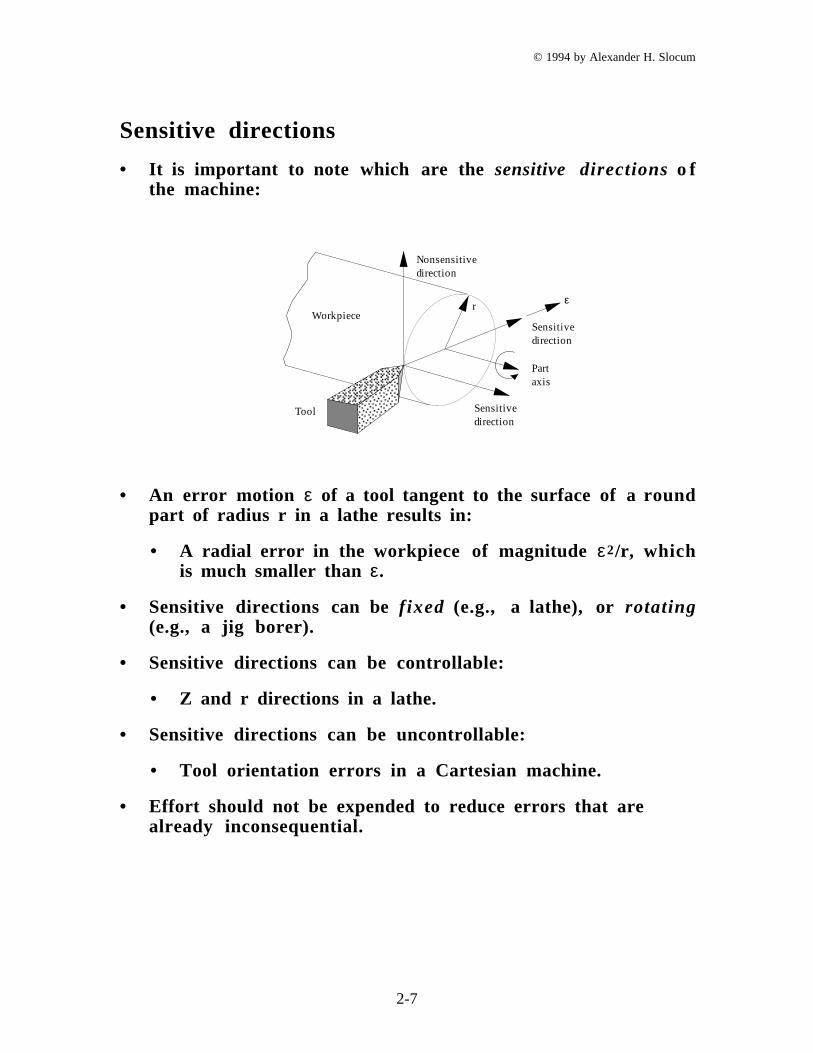
• It is important to note which are the sensitive directions o fthe machine:
������
���������
Sensitive direction
Part axis
Sensitive direction
Nonsensitive direction
Tool
Workpiece
εr
• An error motion ε of a tool tangent to the surface of a roundpart of radius r in a lathe results in:
• A radial error in the workpiece of magnitude ε2/r, whichis much smaller than ε.
• Sensitive directions can be fixed (e.g., a lathe), or rotating(e.g., a jig borer).
• Sensitive directions can be controllable:
• Z and r directions in a lathe.
• Sensitive directions can be uncontrollable:
• Tool orientation errors in a Cartesian machine.
• Effort should not be expended to reduce errors that arealready inconsequential.
© 1994 by Alexander H. Slocum
2-8
Error assessment and budgeting
• Given all the different types of errors that can affect alldifferent components:
• Keeping track of all the errors is such a daunting task:
• Most engineers don't bother and use "experience" toguide the design.
• It is left up to manufacturing and service to work thebugs out.
• This seems to be a major source of reliability andperformance problems.
• The solution to a successful project is a good budget:
• A project requires a good financial budget to make itfeasible.
• A project requires a good time budget to make itfeasible.
• A project requires a good error budget to make itfeasible.
• In order to make a good error budget for the system, a goodmathematical model is needed.

© 1994 by Alexander H. Slocum
2-9
Homogeneous transformation matrices for errorassessment and budgeting
• Allows the designer to consider one part of the machine at atime, and then link them all together like beads on a string.
• Based on rigid body model of a linear series (open chain) ofcoordinate frames.
• Takes into account linear and angular offsets betweencoordinate frames.
• Transforms XYZ coordinates of one frame into XYZcoordinates of another frame:
X
Y
Z
X
Y
Z
1
1 1
R
R R
a, b, c
• Used to transform locally referenced errors into errorsreferenced with respect to the toolpoint and the workpiece.
• Coordinate frames are placed at bearings, joints, and areaswhere other parameters are lumped.
• Closed chains (e.g. a five point bearing mount) need to bemodeled with the generation of constraint equations.
© 1994 by Alexander H. Slocum
2-10
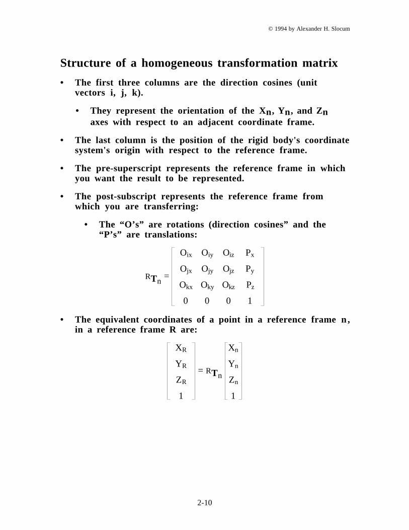
Structure of a homogeneous transformation matrix
• The first three columns are the direction cosines (unitvectors i, j, k).
• They represent the orientation of the Xn, Yn, and Znaxes with respect to an adjacent coordinate frame.
• The last column is the position of the rigid body's coordinatesystem's origin with respect to the reference frame.
• The pre-superscript represents the reference frame in whichyou want the result to be represented.
• The post-subscript represents the reference frame fromwhich you are transferring:
• The “O’s” are rotations (direction cosines” and the“P’s” are translations:
RTn =
Oix Oiy Oiz Px
Ojx Ojy Ojz Py
Okx Oky Okz Pz
0 0 0 1
• The equivalent coordinates of a point in a reference frame n ,in a reference frame R are:
XR
YR
ZR
1
= RTn
Xn
Yn
Zn
1
© 1994 by Alexander H. Slocum
2-11
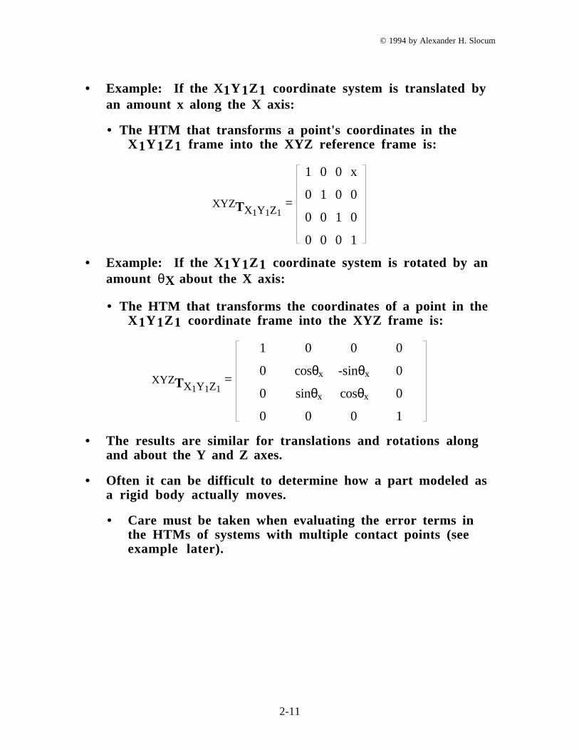
• Example: If the X1Y 1Z1 coordinate system is translated byan amount x along the X axis:
• The HTM that transforms a point's coordinates in theX 1Y 1Z 1 frame into the XYZ reference frame is:
XYZTX1Y1Z1 =
1 0 0 x
0 1 0 0
0 0 1 0
0 0 0 1
• Example: If the X1Y 1Z1 coordinate system is rotated by anamount θX about the X axis:
• The HTM that transforms the coordinates of a point in theX 1Y 1Z 1 coordinate frame into the XYZ frame is:
XYZTX1Y1Z1 =
1 0 0 0
0 cosθx -sinθx 0
0 sinθx cosθx 0
0 0 0 1
• The results are similar for translations and rotations alongand about the Y and Z axes.
• Often it can be difficult to determine how a part modeled asa rigid body actually moves.
• Care must be taken when evaluating the error terms inthe HTMs of systems with multiple contact points (seeexample later).
© 1994 by Alexander H. Slocum
2-12
• Transformation from the Nth axis to the reference systemwill be the sequential product of all the HTMs:
RTN = Tmm-1 = T1
0 T21 T3
2 . . . . ∏m = 1
N
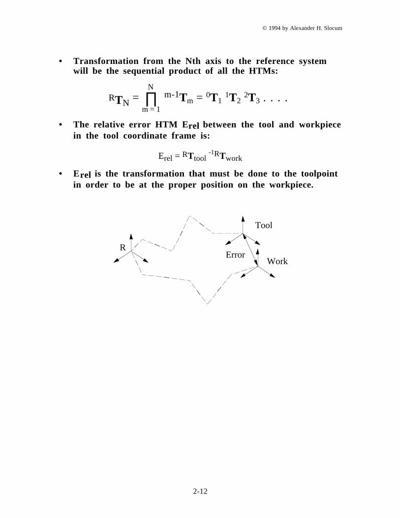
• The relative error HTM E rel between the tool and workpiecein the tool coordinate frame is:
Erel = RTtool -1RTwork
• Erel is the transformation that must be done to the toolpointin order to be at the proper position on the workpiece.
R
Tool
WorkError
© 1994 by Alexander H. Slocum
2-13
• One must consider how the axes will be required to move(order) in order to create the desired motion.
• For the general case of a machine with revolute andtranslational axes.
• Most machine tools and CMMs have only translational axes.
• The error correction vector RPcorrection with respect tothe reference coordinate frame can be obtained from:
Px
Py
Pz correction
R
=
Px
Py
Pz work
R
-
Px
Py
Pz tool
R
• Because of Abbe offsets and angular orientation errors ofthe axes:
• RPcorrection will not necessarily be equal to the positionvector P component of Erel .
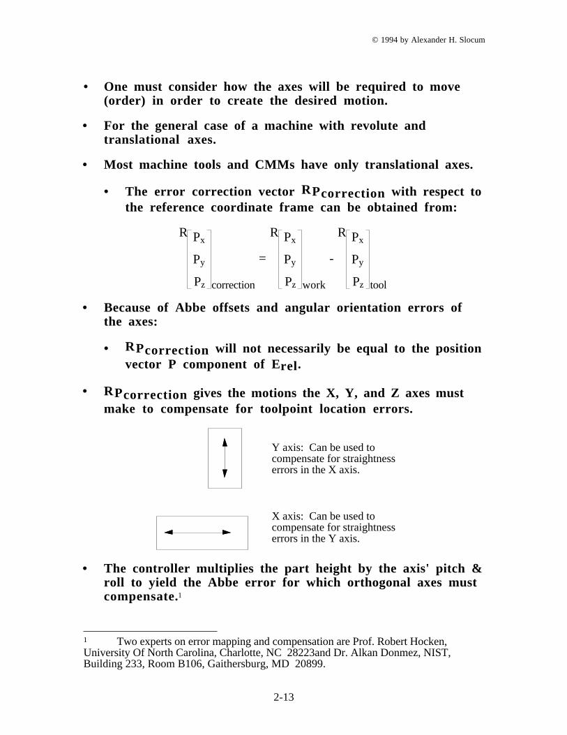
• RPcorrection gives the motions the X, Y, and Z axes mustmake to compensate for toolpoint location errors.
Y axis: Can be used to compensate for straightness errors in the X axis.
X axis: Can be used to compensate for straightness errors in the Y axis.
• The controller multiplies the part height by the axis' pitch &roll to yield the Abbe error for which orthogonal axes mustcompensate.1
1 Two experts on error mapping and compensation are Prof. Robert Hocken,University Of North Carolina, Charlotte, NC 28223and Dr. Alkan Donmez, NIST,Building 233, Room B106, Gaithersburg, MD 20899.
© 1994 by Alexander H. Slocum
2-14
Rigid body models of machine components
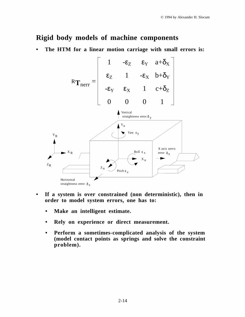
• The HTM for a linear motion carriage with small errors is:
RTnerr =
1 -εZ εY a+δX
εZ 1 -εX b+δY
-εY εX 1 c+δZ
0 0 0 1Vertical straightness error
Roll
Pitch zε
xεX axis servoerror δx
Horizontalstraightness error δ z
Yaw yεY R
RX
RZ
δ y
Z n
X n
Yn
• If a system is over constrained (non deterministic), then inorder to model system errors, one has to:
• Make an intelligent estimate.
• Rely on experience or direct measurement.
• Perform a sometimes-complicated analysis of the system(model contact points as springs and solve the constraintproblem).
© 1994 by Alexander H. Slocum
2-15
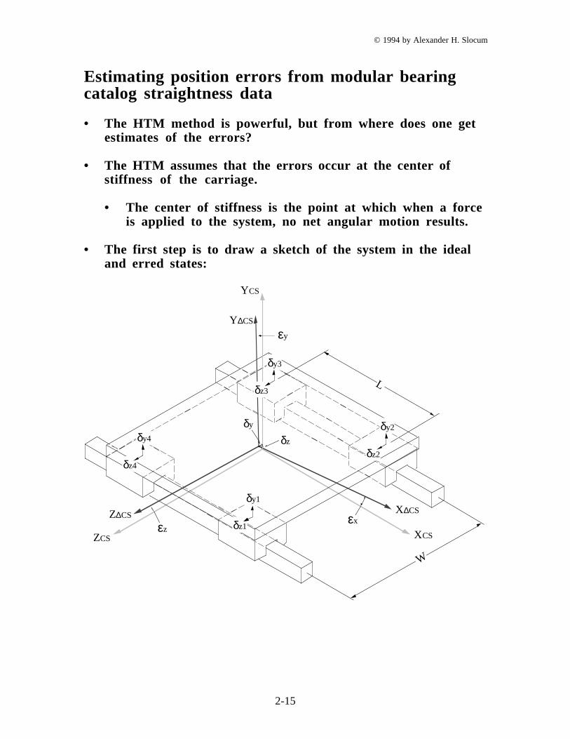
Estimating position errors from modular bearingcatalog straightness data
• The HTM method is powerful, but from where does one getestimates of the errors?
• The HTM assumes that the errors occur at the center ofstiffness of the carriage.
• The center of stiffness is the point at which when a forceis applied to the system, no net angular motion results.
• The first step is to draw a sketch of the system in the idealand erred states:
δy
δz
XCS
YCS
ZCS
X∆CS
Y∆CS
Z∆CS
εz
εy
εxδz1
δy1
δz4
δy4
δz3
δy3
δz2
δy2
L
W
© 1994 by Alexander H. Slocum
2-16
• Consider the elements of the HTM we are searching for:
Xcs
Ycs
Zcs
1
=
1 -εZ εY a+δX
εZ 1 -εX b+δY
-εY εX 1 c+δZ
0 0 0 1
X∆cs
Y∆cs
Z∆cs
1
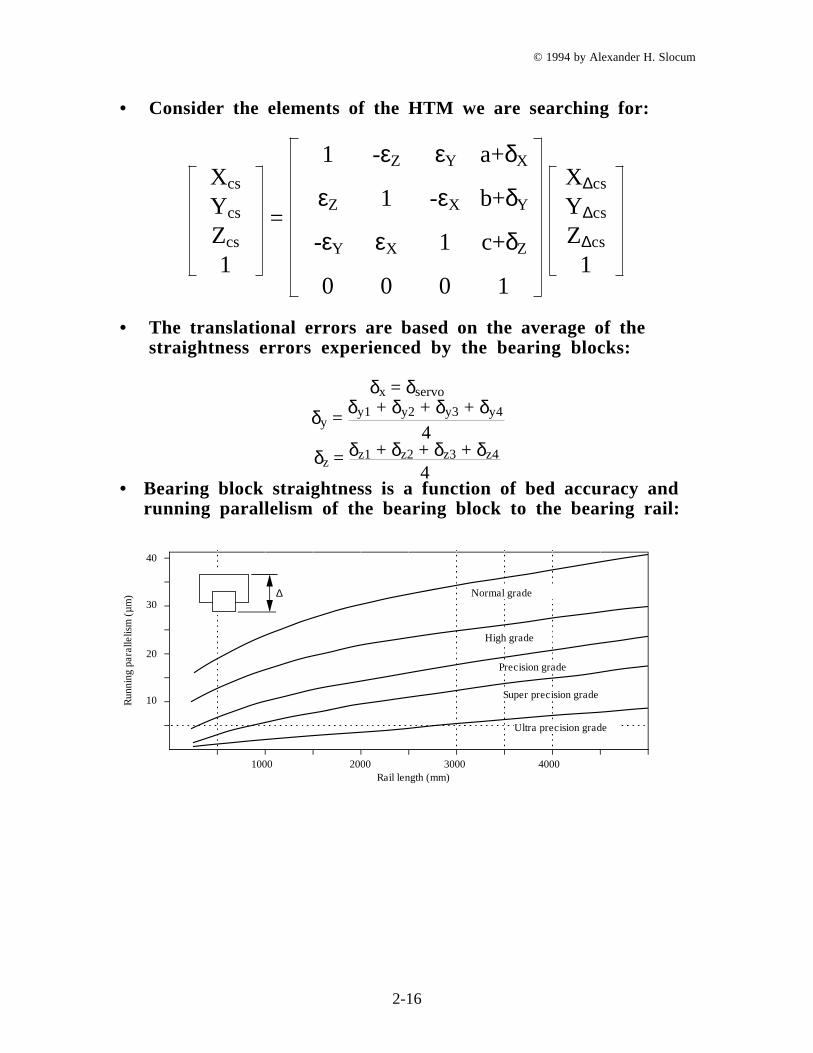
• The translational errors are based on the average of thestraightness errors experienced by the bearing blocks:
δx = δservo
δy = δy1 + δy2 + δy3 + δy4
4δz = δz1 + δz2 + δz3 + δz4
4• Bearing block straightness is a function of bed accuracy and
running parallelism of the bearing block to the bearing rail:
����������������
����������������
�������
�������
�������
�������
�������
�������
�������
�������
�������
����������������
1000 2000 3000 4000
Run
ning
pa
ralle
lism
(µ
m)
������������������������������������������������
40
30
20
10
Rail length (mm)
��������������������������������Normal grade
High grade
Precision grade
Super precision grade
Ultra precision grade
∆

© 1994 by Alexander H. Slocum
2-17
• The angular errors are based on the differences in theaverage straightness errors experienced by pairs of bearingblocks acting across the carriage:
εx =
δy2 + δy3
2 -
δy1 + δy4
2W
εy =
δz3 + δz4
2 -
δz1 + δz2
2L
εz =
δy1 + δy2
2 -
δy3 + δy4
2L
• Note we assumed for the starightness we assumed all theerrors are acting in the same direction.
• Here we assume one set of errors acts up, and the other actsdown.
• This is very conservative (makes up for other effects wemight miss).
© 1994 by Alexander H. Slocum
2-18
Example
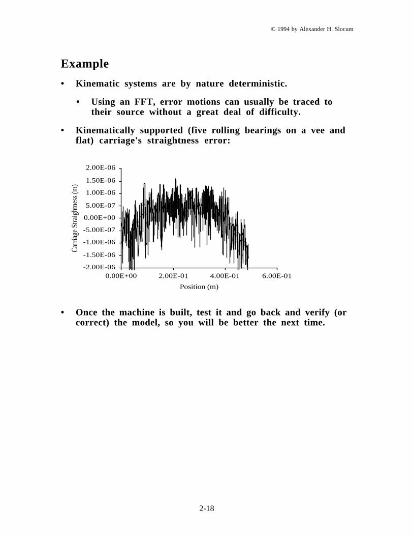
• Kinematic systems are by nature deterministic.
• Using an FFT, error motions can usually be traced totheir source without a great deal of difficulty.
• Kinematically supported (five rolling bearings on a vee andflat) carriage's straightness error:
Position (m)
Car
riage
Stra
ight
ness
(m)
-2.00E-06
-1.50E-06
-1.00E-06
-5.00E-07
0.00E+00
5.00E-07
1.00E-06
1.50E-06
2.00E-06
0.00E+00 2.00E-01 4.00E-01 6.00E-01
• Once the machine is built, test it and go back and verify (orcorrect) the model, so you will be better the next time.
© 1994 by Alexander H. Slocum
2-19
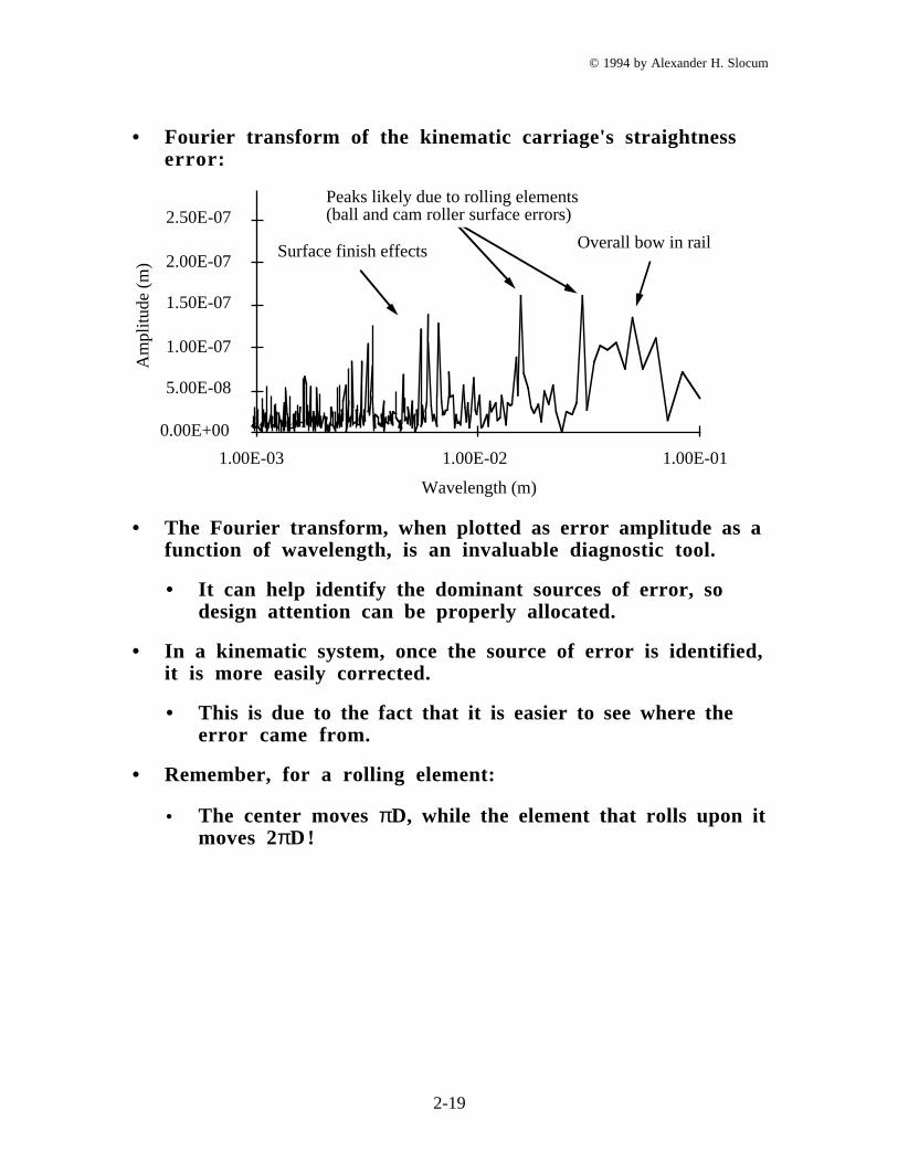
• Fourier transform of the kinematic carriage's straightnesserror:
0.00E+00
5.00E-08
1.00E-07
1.50E-07
2.00E-07
2.50E-07
1.00E-03 1.00E-02 1.00E-01
Wavelength (m)
Am
plitu
de (
m)
Overall bow in railSurface finish effects
Peaks likely due to rolling elements (ball and cam roller surface errors)
• The Fourier transform, when plotted as error amplitude as afunction of wavelength, is an invaluable diagnostic tool.
• It can help identify the dominant sources of error, sodesign attention can be properly allocated.
• In a kinematic system, once the source of error is identified,it is more easily corrected.
• This is due to the fact that it is easier to see where theerror came from.
• Remember, for a rolling element:
• The center moves πD, while the element that rolls upon itmoves 2πD!
© 1994 by Alexander H. Slocum
2-20
Rigid body models
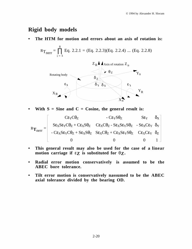
• The HTM for motion and errors about an axis of rotation is:
RTnerr = Eq. 2.2.1 = (Eq. 2.2.3)(Eq. 2.2.4) ... (Eq. 2.2.8)∏
i = 3
8
Z R
X R
Zθ
εYδ Xδε
RY
nY
X n
Zδ
nZAxis of rotation
X Y
Rotating body
• With S = Sine and C = Cosine, the general result is:
RTnerr =
CεYCθZ - CεYSθZ SεY δX
SεXSεYCθZ + CεXSθZ CεXCθZ - SεXSεYSθZ - SεXCεY δY
- CεXSεYCθZ + SεXSθZ SεXCθZ + CεXSεYSθZ CεXCεY δZ
0 0 0 1
• This general result may also be used for the case of a linearmotion carriage if εZ is substituted for θZ .
• Radial error motion conservatively is assumed to be theABEC bore tolerance.
• Tilt error motion is conservatively nassumed to be the ABECaxial tolerance divided by the bearing OD.
© 1994 by Alexander H. Slocum
2-21
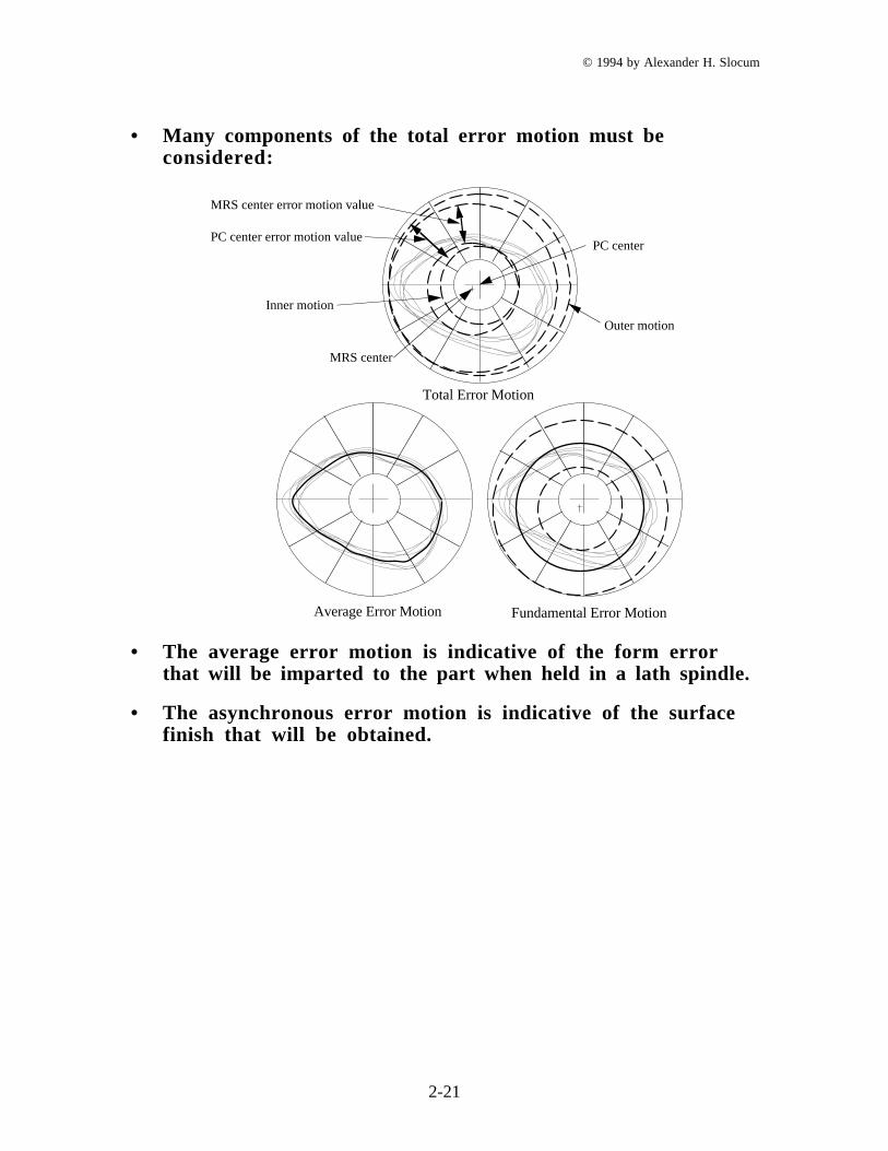
• Many components of the total error motion must beconsidered:
Average Error Motion Fundamental Error Motion
Total Error Motion
PC center
MRS center
Inner motion
MRS center error motion value
PC center error motion value
Outer motion
• The average error motion is indicative of the form errorthat will be imparted to the part when held in a lath spindle.
• The asynchronous error motion is indicative of the surfacefinish that will be obtained.
© 1994 by Alexander H. Slocum
2-22
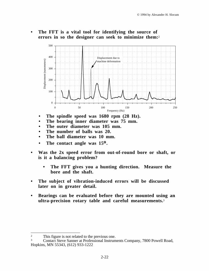
• The FFT is a vital tool for identifying the source oferrors in so the designer can seek to minimize them:2
250200150100500
0
100
200
300
400
500
Frequency (Hz)
Dis
plac
emen
t (na
nom
eter
s) Displacement due to machine deformation
• The spindle speed was 1680 rpm (28 Hz).• The bearing inner diameter was 75 mm.• The outer diameter was 105 mm.• The number of balls was 20.• The ball diameter was 10 mm.• The contact angle was 15o.
• Was the 2x speed error from out-of-round bore or shaft, oris it a balancing problem?
• The FFT gives you a hunting direction. Measure thebore and the shaft.
• The subject of vibration-induced errors will be discussedlater on in greater detail.
• Bearings can be evaluated before they are mounted using anultra-precision rotary table and careful measurements.3
2 This figure is not related to the previous one.3 Contact Steve Sanner at Professional Instruments Company, 7800 Powell Road,Hopkins, MN 55343, (612) 933-1222

© 1994 by Alexander H. Slocum
2-23
Error types
• Geometric errors:
• Errors in the form of individual machine components:
• Component straightness error due to machiningerrors.
• Component straightness error due to gravity loading.
• Surface finish effects.
• Quasi-static accuracy of surfaces moving relative to eachother (e.g., linear or rotary motion axes):
• Linear motion axis:
• Pitch.
• Roll.
• Yaw.
• Straightness (2 components).
• Linear displacement.
• Rotary motion axis:
• Radial motion (2 components in fixed coordinate
frame, 1 component in rotating frame.)
• Axial motion.
• Tilt motion (2 components).
• Angular motion about axis of rotation.
© 1994 by Alexander H. Slocum
2-24
• Kinematic errors:
• Errors in an axis's trajectory that are caused bymisaligned or improperly sized components.
• Orthogonality between axes.
• Parallelism between axes.
• Error motions in a closed kinematic chain.
• External load induced errors:
• Errors due to deformation of components:
• Gravity load induced errors.
• Cutting/probing force induced errors.
• Axis acceleration load induced errors.
© 1994 by Alexander H. Slocum
2-25
• Thermal errors:
• Mean temperature other than 68 °F (20 °C).
• Gradients in environment's temperature.
• Errors caused by thermal expansion of elements:
• External heat sources:
• Mean temperature of the room.
• Sun shining through the window onto the machine.
• Nearby machine's hot air vent.
• Overhead lights.
• Operator's body heat.
• Internal heat sources:
• Motors.
• Bearings.
• Machining process.
• Pumps.
• Expansion of compressed fluids.
© 1994 by Alexander H. Slocum
2-26
• Dynamic errors:
• Errors caused by vibration or control processes:
• Vibration:
• External environment.
• Cutting process.
• Rotating masses.
• Control system:
• Algorithm type (e.g., PID, adaptive, etc.).
• Stick-slip friction.
• Varying mass.
• Varying stiffness.
• Switching amplifiers
• One grinding machine was plagued by“washboard” which had the same pitch regardlessof table speed.
• The problem was eliminated when the spindlemotor switching amplifier was changed from 10kHz to 30 kHz!
© 1994 by Alexander H. Slocum
2-27
• Instrumentation errors:
• Errors associated with sensors:
• Intrinsic accuracy.
• Interpolation.
• M ounting errors:
• Position.
• Mounting stress.
• Calibration (error associated with the mastering process).
© 1994 by Alexander H. Slocum
2-28
• Computational errors:
• Error introduced in the analysis algorithms.
• Rounding off errors due to hardware.
• Additional sources of error (often very difficult to model):
• Humidity.
• Loose Joints.
• Dirt.
• Variations in supply systems:
• Electricity.
• Fluid pressure.
• Operator inattention.
• Fluid supply cleanliness.
• Operators (“52-2” factor)
© 1994 by Alexander H. Slocum
2-29
Combinational rules for errors
• 3 Common types of errors which can be mixed in differentways:
• Random - under apparently equal conditions at a givenposition, errors that do not always have the same value,and can only be expressed statistically.
• Systematic - which always have the same value and signat a given position and under given circumstances.
• Generally can be correlated with position along anaxis and can be corrected.
• If the relative accompanying random error issmall enough.
• Hysteresis - a systematic error which in this instance isseparated out for convenience.
• Usually repeatable, sign depends on the direction ofapproach, and magnitude partly dependent on the travel.
• May be compensated for if the direction of approach isknown and an adequate pre-travel is made.
© 1994 by Alexander H. Slocum
2-30
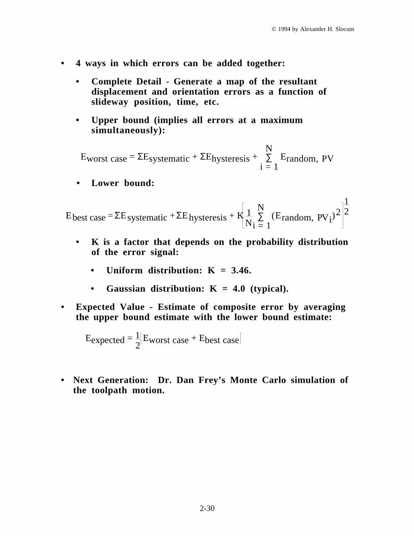
• 4 ways in which errors can be added together:
• Complete Detail - Generate a map of the resultantdisplacement and orientation errors as a function ofslideway position, time, etc.
• Upper bound (implies all errors at a maximumsimultaneously):
Eworst case = ΣEsystematic + ΣEhysteresis + ∑i = 1
NErandom, PV
• Lower bound:
Ebest case = ΣEsystematic + ΣEhysteresis + K 1N
(Erandom, PVi)2∑
i = 1
N12
• K is a factor that depends on the probability distributionof the error signal:
• Uniform distribution: K = 3.46.
• Gaussian distribution: K = 4.0 (typical).
• Expected Value - Estimate of composite error by averagingthe upper bound estimate with the lower bound estimate:
Eexpected = 12
Eworst case + Ebest case
• Next Generation: Dr. Dan Frey’s Monte Carlo simulation ofthe toolpath motion.