8100 led - acuity brandshydrel.acuitybrands.com/products/detail/255244/hydrel/8100-led... ·...
TRANSCRIPT
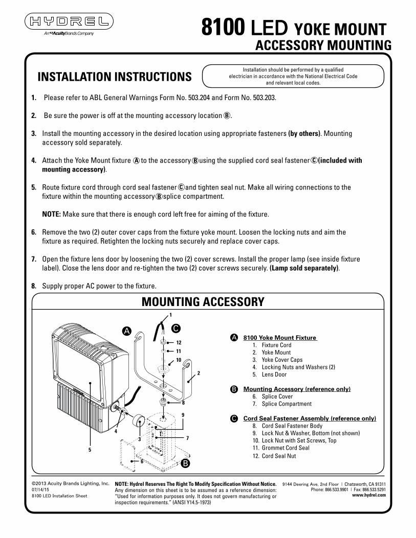
1. Please refer to ABL General Warnings Form No. 503.204 and Form No. 503.203.
2. Be sure the power is off at the mounting accessory location .
3. Install the mounting accessory in the desired location using appropriate fasteners (by others). Mountingaccessory sold separately.
4. Attach the Yoke Mount fixture to the accessory using the supplied cord seal fastener (included withmounting accessory).
5. Route fixture cord through cord seal fastener and tighten seal nut. Make all wiring connections to thefixture within the mounting accessory splice compartment.
NOTE: Make sure that there is enough cord left free for aiming of the fixture.
6. Remove the two (2) outer cover caps from the fixture yoke mount. Loosen the locking nuts and aim thefixture as required. Retighten the locking nuts securely and replace cover caps.
7. Open the fixture lens door by loosening the two (2) cover screws. Install the proper lamp (see inside fixturelabel). Close the lens door and re-tighten the two (2) cover screws securely. (Lamp sold separately).
8. Supply proper AC power to the fixture.
Installation should be performed by a qualified electrician in accordance with the National Electrical Code
and relevant local codes.INSTALLATION INSTRUCTIONS
8100 LED YOKE MOUNTACCESSORY MOUNTING
MOUNTING ACCESSORY
C
B
A8100 Yoke Mount Fixture
1. Fixture Cord 2. Yoke Mount 3. Yoke Cover Caps 4. Locking Nuts and Washers (2) 5. Lens Door
Mounting Accessory (reference only)6. Splice Cover 7. Splice Compartment
Cord Seal Fastener Assembly (reference only)8. Cord Seal Fastener Body 9. Lock Nut & Washer, Bottom (not shown) 10. Lock Nut with Set Screws, Top 11. Grommet Cord Seal 12. Cord Seal Nut
1
12
11
10
2
8
9
74
3
5
6
A
B
CB
C
B
A
B
C
NOTE: Hydrel Reserves The Right To Modify Specification Without Notice. Any dimension on this sheet is to be assumed as a reference dimension: “Used for information purposes only. It does not govern manufacturing or inspection requirements.” (ANSI Y14.5-1973)
©2013 Acuity Brands Lighting, Inc. 07/14/15
8100 LED Installation Sheet
9144 Deering Ave, 2nd Floor | Chatsworth, CA 91311 Phone: 866.533.9901 | Fax: 866.533.5291
www.hydrel.com

Installation should be performed by a qualified electrician in accordance with the National Electrical Code
and relevant local codes.INSTALLATION INSTRUCTIONS
18”(470)
6”(152)
MOUNTING ACCESSORIES
8100 COB YOKE MOUNT
NOTE: Hydrel Reserves The Right To Modify Specification Without Notice. Any dimension on this sheet is to be assumed as a reference dimension: “Used for information purposes only. It does not govern manufacturing or inspection requirements.” (ANSI Y14.5-1973)
©2013 Acuity Brands Lighting, Inc. 07/14/15
8100 LED Installation Sheet
9144 Deering Ave, 2nd Floor | Chatsworth, CA 91311 Phone: 866.533.9901 | Fax: 866.533.5291
www.hydrel.com
1
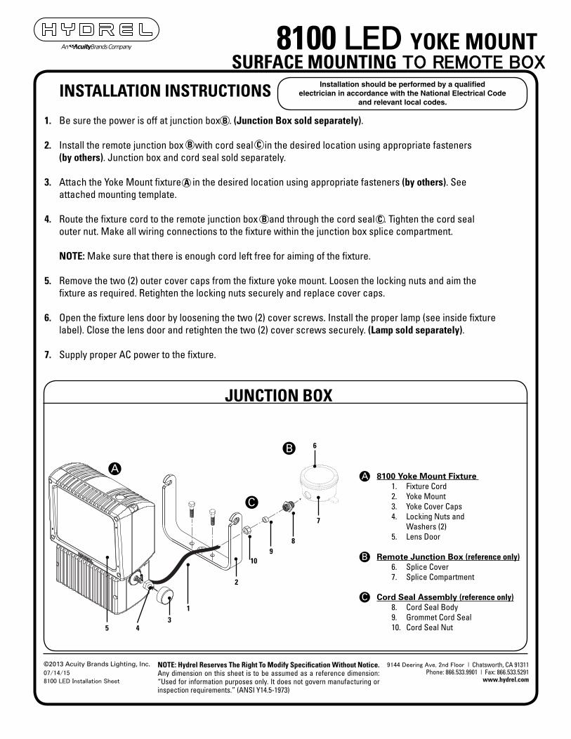
1. Be sure the power is off at junction box . (Junction Box sold separately).
2. Install the remote junction box with cord seal in the desired location using appropriate fasteners(by others). Junction box and cord seal sold separately.
3. Attach the Yoke Mount fixture in the desired location using appropriate fasteners (by others). Seeattached mounting template.
4. Route the fixture cord to the remote junction box and through the cord seal . Tighten the cord sealouter nut. Make all wiring connections to the fixture within the junction box splice compartment.
NOTE: Make sure that there is enough cord left free for aiming of the fixture.
5. Remove the two (2) outer cover caps from the fixture yoke mount. Loosen the locking nuts and aim thefixture as required. Retighten the locking nuts securely and replace cover caps.
6. Open the fixture lens door by loosening the two (2) cover screws. Install the proper lamp (see inside fixturelabel). Close the lens door and retighten the two (2) cover screws securely. (Lamp sold separately).
7. Supply proper AC power to the fixture.
Installation should be performed by a qualified electrician in accordance with the National Electrical Code
and relevant local codes.INSTALLATION INSTRUCTIONS
8100 LED YOKE MOUNTSURFACE MOUNTING TO REMOTE BOX
JUNCTION BOX
C
B
8100 Yoke Mount Fixture 1. Fixture Cord 2. Yoke Mount 3. Yoke Cover Caps 4. Locking Nuts and
Washers (2)5. Lens Door
Remote Junction Box (reference only)6. Splice Cover 7. Splice Compartment
Cord Seal Assembly (reference only)8. Cord Seal Body 9. Grommet Cord Seal 10. Cord Seal Nut
1
A
1
2
345
A
B
C
A
B
B
B
C
C
6
7
89
10
NOTE: Hydrel Reserves The Right To Modify Specification Without Notice. Any dimension on this sheet is to be assumed as a reference dimension: “Used for information purposes only. It does not govern manufacturing or inspection requirements.” (ANSI Y14.5-1973)
9144 Deering Ave, 2nd Floor | Chatsworth, CA 91311 Phone: 866.533.9901 | Fax: 866.533.5291
www.hydrel.com
©2013 Acuity Brands Lighting, Inc. 07/14/15
8100 LED Installation Sheet

2 3/4”(70)
1 3/8”(35)
7 8” (22) Center mount
hole (accessory mounting)
Two (2) mounting holes for (10) fasteners (by others)3 8”
8100 LED YOKE MOUNT YOKE TEMPLATE (NOT TO SCALE)
Installation should be performed by a qualified electrician in accordance with the National Electrical Code
and relevant local codes.INSTALLATION INSTRUCTIONS
NOTE: Hydrel Reserves The Right To Modify Specification Without Notice. Any dimension on this sheet is to be assumed as a reference dimension: “Used for information purposes only. It does not govern manufacturing or inspection requirements.” (ANSI Y14.5-1973)
©2013 Acuity Brands Lighting, Inc. 07/14/15
8100 LED Installation Sheet
9144 Deering Ave, 2nd Floor | Chatsworth, CA 91311 Phone: 866.533.9901 | Fax: 866.533.5291
www.hydrel.com
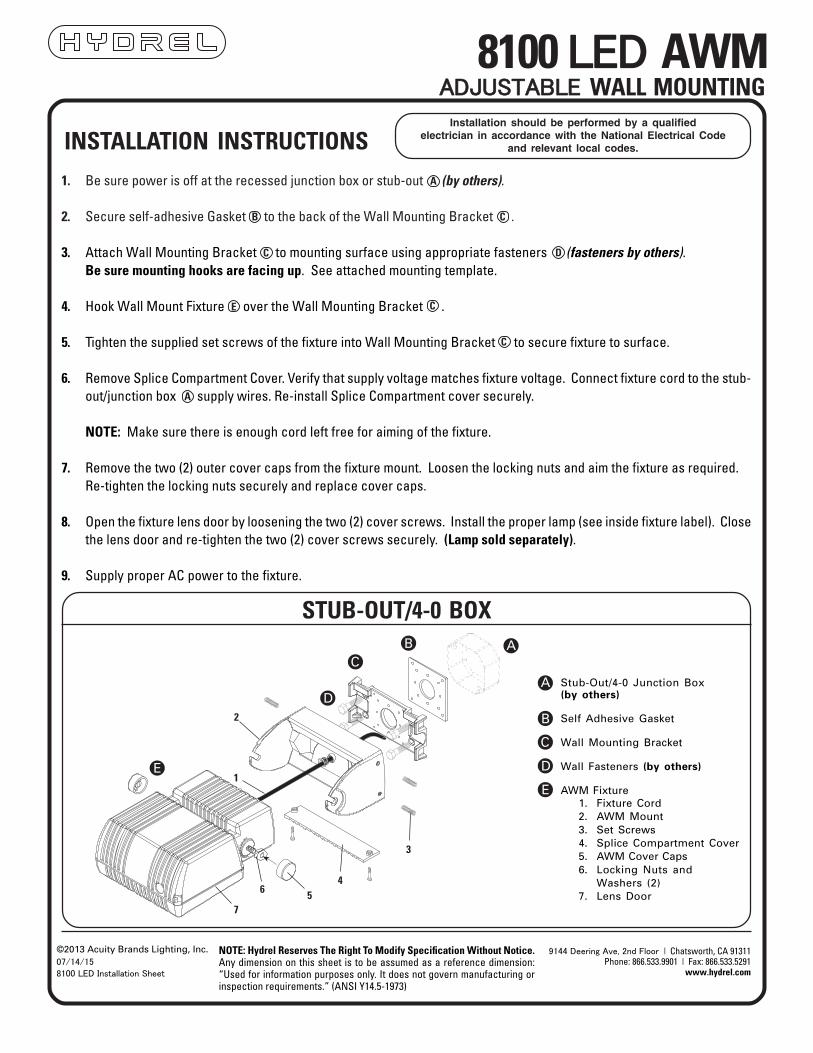
1. Be sure power is off at the recessed junction box or stub-out (by others).
2. Secure self-adhesive Gasket to the back of the Wall Mounting Bracket .
3. Attach Wall Mounting Bracket to mounting surface using appropriate fasteners (fasteners by others).Be sure mounting hooks are facing up. See attached mounting template.
4. Hook Wall Mount Fixture over the Wall Mounting Bracket .
5. Tighten the supplied set screws of the fixture into Wall Mounting Bracket to secure fixture to surface.
6. Remove Splice Compartment Cover. Verify that supply voltage matches fixture voltage. Connect fixture cord to the stub-out/junction box supply wires. Re-install Splice Compartment cover securely.
NOTE: Make sure there is enough cord left free for aiming of the fixture.
7. Remove the two (2) outer cover caps from the fixture mount. Loosen the locking nuts and aim the fixture as required.Re-tighten the locking nuts securely and replace cover caps.
8. Open the fixture lens door by loosening the two (2) cover screws. Install the proper lamp (see inside fixture label). Closethe lens door and re-tighten the two (2) cover screws securely. (Lamp sold separately).
9. Supply proper AC power to the fixture.
Installation should be performed by a qualifiedelectrician in accordance with the National Electrical Code
and relevant local codes.INSTALLATION INSTRUCTIONS
8100 LED AWMADJUSTABLE WALL MOUNTING
STUB-OUT/4-0 BOX
E
A
C
Stub-Out/4-0 Junction Box(by others)
Self Adhesive Gasket
Wall Mounting Bracket
Wall Fasteners (by others)
AWM Fixture1. Fixture Cord2. AWM Mount3. Set Screws4. Splice Compartment Cover5. AWM Cover Caps6. Locking Nuts and
Washers (2)7. Lens Door
A
B
C
D
E
ABC
E
C
B
D
C
C
D
756
4
3
2
1
A
NOTE: Hydrel Reserves The Right To Modify Specification Without Notice. Any dimension on this sheet is to be assumed as a reference dimension: “Used for information purposes only. It does not govern manufacturing or inspection requirements.” (ANSI Y14.5-1973)
©2013 Acuity Brands Lighting, Inc. 07/14/15
8100 LED Installation Sheet
9144 Deering Ave, 2nd Floor | Chatsworth, CA 91311 Phone: 866.533.9901 | Fax: 866.533.5291
www.hydrel.com

1. Be sure power is off before wiring.
2. Attach Wall Mounting Bracket to mounting surface using appropriate fasteners (fasteners by others).Be sure mounting hooks are facing up. See attached mounting template.
3. Hook Wall Mount Fixture over the Wall Mounting Bracket .
4. Tighten the supplied set screws of the fixture into Wall Mounting Bracket to secure fixture to surface.
5. Connect supply conduit and install electrical wiring to the fixture.
6. Remove Splice Compartment Cover. Verify that supply voltage matches fixture voltage. Connect fixture cord to theconduit supply wires. Reinstall splice compartment cover securely.
NOTE: Make sure there is enough cord left free for aiming of the fixture.
7. Remove the two (2) outer cover caps from the fixture mount. Loosen the locking nuts and aim the fixture as required.Re-tighten the locking nuts securely and replace cover caps.
8. Open the fixture lens door by loosening the two (2) cover screws. Install the proper lamp (see inside fixture label). Closethe lens door and re-tighten the two (2) cover screws securely. (Lamp sold separately).
9. Supply proper AC power to the fixture.
Installation should be performed by a qualifiedelectrician in accordance with the National Electrical Code
and relevant local codes.INSTALLATION INSTRUCTIONS
8100 LED AWMDEWALL MOUNTING-SURFACE CONDUIT
INSTALLATION DIAGRAM
Wall Mount Bracket
Wall Fasteners(by others)
AWM Fixture1. Fixture Cord2. AWM Mount3. Set Screws4. Splice Compartment Cover5. AWM Cover Caps6. Locking Nuts and
Washers (2)7. Lens Door
Conduit (by others)
A
C
A
D
A
AB
DB
B
C
A
B
C
D
75
6
2
1
4
3
1
NOTE: Hydrel Reserves The Right To Modify Specification Without Notice. Any dimension on this sheet is to be assumed as a reference dimension: “Used for information purposes only. It does not govern manufacturing or inspection requirements.” (ANSI Y14.5-1973)
©2013 Acuity Brands Lighting, Inc. 07/14/15
8100 LED Installation Sheet
9144 Deering Ave, 2nd Floor | Chatsworth, CA 91311 Phone: 866.533.9901 | Fax: 866.533.5291
www.hydrel.com

8100 LED AWM/AWMDEWALL MOUNTING BRACKET TEMPLATE (NOT TO SCALE)
Installation should be performed by a qualifiedelectrician in accordance with the National Electrical Code
and relevant local codes.
NOTE: Hydrel Reserves The Right To Modify Specification Without Notice. Any dimension on this sheet is to be assumed as a reference dimension: “Used for information purposes only. It does not govern manufacturing or inspection requirements.” (ANSI Y14.5-1973)
©2013 Acuity Brands Lighting, Inc. 07/14/15
8100 LED Installation Sheet
9144 Deering Ave, 2nd Floor | Chatsworth, CA 91311 Phone: 866.533.9901 | Fax: 866.533.5291
www.hydrel.com
Installation should be performed by a qualifiedelectrician in accordance with the National Electrical Code
and relevant local codes.INSTALLATION INSTRUCTIONS
ROUND POLE
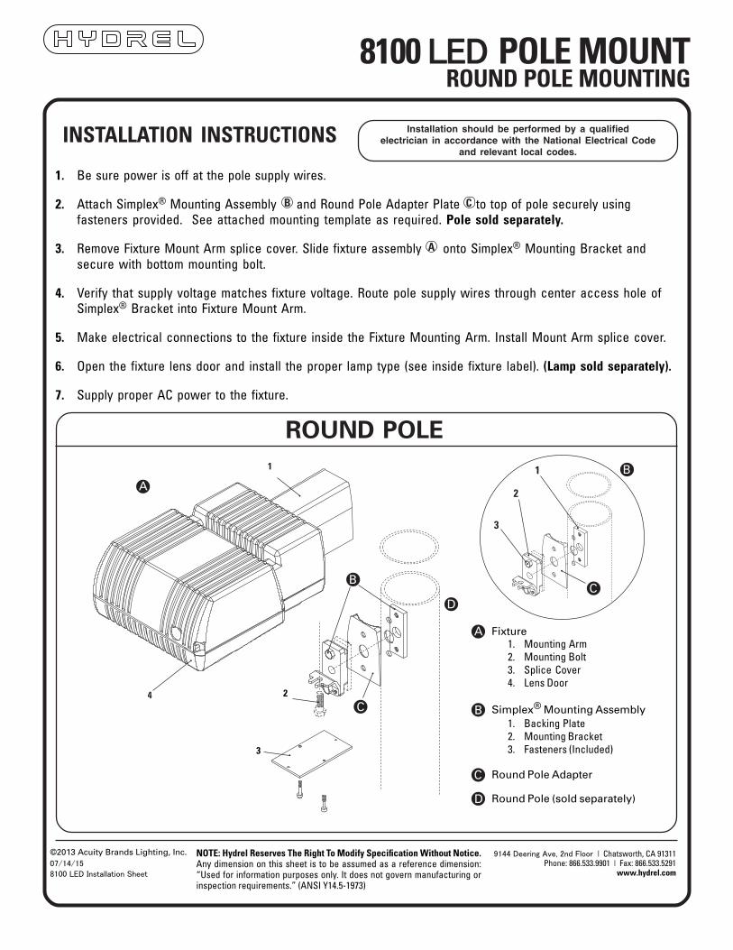
Fixture1. Mounting Arm2. Mounting Bolt3. Splice Cover4. Lens Door
Simplex® Mounting Assembly1. Backing Plate2. Mounting Bracket3. Fasteners (Included)
Round Pole Adapter
Round Pole (sold separately)
A
B
C
D
1
2
3
A
1
B
C
CD
B
4
3
2
8100 LED POLE MOUNTROUND POLE MOUNTING
1. Be sure power is off at the pole supply wires.
2. Attach Simplex® Mounting Assembly and Round Pole Adapter Plate to top of pole securely usingfasteners provided. See attached mounting template as required. Pole sold separately.
3. Remove Fixture Mount Arm splice cover. Slide fixture assembly onto Simplex® Mounting Bracket andsecure with bottom mounting bolt.
4. Verify that supply voltage matches fixture voltage. Route pole supply wires through center access hole ofSimplex® Bracket into Fixture Mount Arm.
5. Make electrical connections to the fixture inside the Fixture Mounting Arm. Install Mount Arm splice cover.
6. Open the fixture lens door and install the proper lamp type (see inside fixture label). (Lamp sold separately).
7. Supply proper AC power to the fixture.
CB
A
NOTE: Hydrel Reserves The Right To Modify Specification Without Notice. Any dimension on this sheet is to be assumed as a reference dimension: “Used for information purposes only. It does not govern manufacturing or inspection requirements.” (ANSI Y14.5-1973)
©2013 Acuity Brands Lighting, Inc. 07/14/15
8100 LED Installation Sheet
9144 Deering Ave, 2nd Floor | Chatsworth, CA 91311 Phone: 866.533.9901 | Fax: 866.533.5291
www.hydrel.com

Installation should be performed by a qualifiedelectrician in accordance with the National Electrical Code
and relevant local codes.INSTALLATION INSTRUCTIONS
SQUARE POLE
Fixture
Extrusion
Simplex® Mounting Assembly1. Backing Plate2. Mounting Bracket3. Fasteners (Included)
Extrusion Cover
A
B
C
D
1
2
3
A B
C
D
C
1. Be sure power is off at the pole supply wires.
2. Attach Simplex® Mounting assembly to top of pole securely using supplied fasteners provided.See attached mounting template.
3. Slide Fixture assembly onto Simplex® Mounting Bracket and secure with bottom mounting screw.
4. Verify that supply voltage matches fixture voltage. Route service wires through center access hole ofSimplex® Bracket.
5. Make electrical connections to the fixture inside the extrusion.
6. Attach Extrusion Cover..
7. Open the fixture door and install the proper lamp type (see inside fixture label). (Lamp sold separately).
C
A
8100 LED POLE MOUNTSQUARE POLE MOUNTING
NOTE: Hydrel Reserves The Right To Modify Specification Without Notice. Any dimension on this sheet is to be assumed as a reference dimension: “Used for information purposes only. It does not govern manufacturing or inspection requirements.” (ANSI Y14.5-1973)
©2013 Acuity Brands Lighting, Inc. 07/14/15
8100 LED Installation Sheet
9144 Deering Ave, 2nd Floor | Chatsworth, CA 91311 Phone: 866.533.9901 | Fax: 866.533.5291
www.hydrel.com
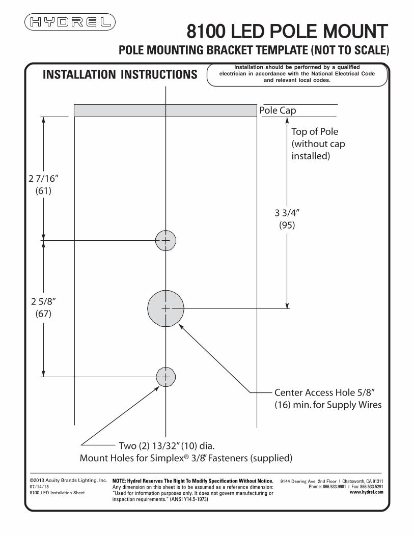
POLE MOUNTING BRACKET TEMPLATE (NOT TO SCALE)Installation should be performed by a qualified
electrician in accordance with the National Electrical Codeand relevant local codes.
INSTALLATION INSTRUCTIONS
8100 LED POLE MOUNT
NOTE: Hydrel Reserves The Right To Modify Specification Without Notice. Any dimension on this sheet is to be assumed as a reference dimension: “Used for information purposes only. It does not govern manufacturing or inspection requirements.” (ANSI Y14.5-1973)
©2013 Acuity Brands Lighting, Inc. 07/14/15
8100 LED Installation Sheet
9144 Deering Ave, 2nd Floor | Chatsworth, CA 91311 Phone: 866.533.9901 | Fax: 866.533.5291
www.hydrel.com