prasar bharati (broadcasting corporation of india) directorate
TRANSCRIPT

Page 1 of 118
DGDD/TxD/5kWHPT Specs/J&K/2010
PRASAR BHARATI (Broadcasting Corporation of India)
Directorate General Doordarshan
Doordarshan Bhawan, Copernicus Marg
New Delhi - 110001
Specification No: DG:DD/TxD/HPT/SITC J&K Projects/E-V/2010 Dated 14.09.2010
Specifications for SITC of Two Nos. of 5kW fully Solid State UHF Analog TV Transmitters alongwith Station Items to be installed at
Rajouri (AIR FM site) in J & K
Page 2 of 118
DGDD/TxD/5kWHPT Specs/J&K/2010
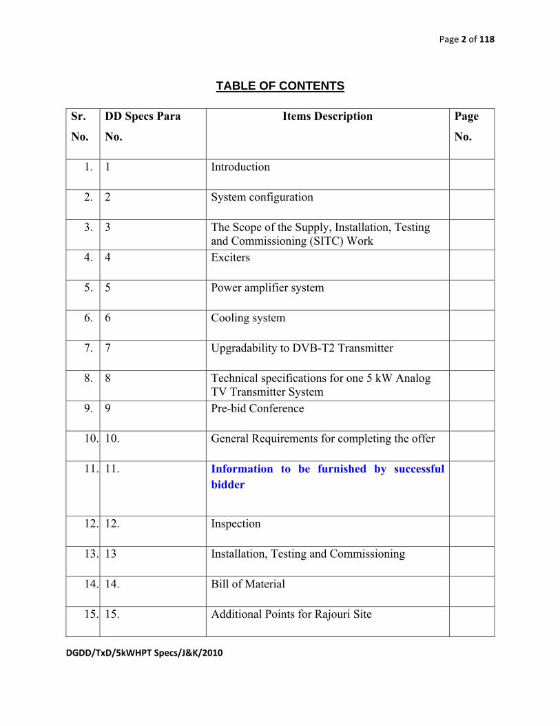
TABLE OF CONTENTS
Sr.
No.
DD Specs Para
No.
Items Description Page
No.
1. 1 Introduction
2. 2 System configuration
3. 3 The Scope of the Supply, Installation, Testing and Commissioning (SITC) Work
4. 4 Exciters
5. 5 Power amplifier system
6. 6 Cooling system
7. 7 Upgradability to DVB-T2 Transmitter
8. 8 Technical specifications for one 5 kW Analog TV Transmitter System
9. 9 Pre-bid Conference
10. 10. General Requirements for completing the offer
11. 11. Information to be furnished by successful bidder
12. 12. Inspection
13. 13 Installation, Testing and Commissioning
14. 14. Bill of Material
15. 15. Additional Points for Rajouri Site

Page 3 of 118
DGDD/TxD/5kWHPT Specs/J&K/2010
16. 16. Compliance Statement
17. Annexure IA Suggestive BOM for 2 Nos. Transmitter systems
18. Annexure IB Suggestive BOM for common items of the two transmitters
19. Annexure I-1 Specifications of 50 kVA AVR
20. Annexure I-2 Specifications of 10kW Broadcast Power Monitor (Through line Power meter)
21. Annexure I-3 Specifications of indoor coaxial lines etc.
22. Annexure I-4 Specifications of input, monitoring equipment and racks
23. Annexure I-4-I Specifications of standard 19” rack
24. Annexure I-4-II Specifications of video equalizing distribution amplifier
25. Annexure I-4-III Specifications of video audio switcher
26. Annexure I-4-IV Specifications of Audio Jack Panel-(N/C) 2x24
27. Annexure I-4-V Specification of video jack panels
28. Annexure I-4-VI Specifications of audio stereo monitoring amplifier 8 W
29. Annexure I-4-VII Specifications of audio distribution amplifier with suitable frame and redundant power supply and extender card
30. Annexure I-4-VIII Specifications for audio processor
31. Annexure I-5 Specifications of Monitoring Equipment
32. Annexure I-5-I Specifications of Waveform Monitor
33. Annexure I-5-II Specifications of VU Meter

Page 4 of 118
DGDD/TxD/5kWHPT Specs/J&K/2010
34. Annexure I-6 Specifications of Installation Materials
35. Annexure I-7 Specifications of computer system with 1 kVA UPS and Laserjet printer
36. Annexure I-8 Specifications of 10 kW dummy load
37. Annexure I-9 Specifications of measuring equipment
38. Annexure I-9-I Specifications of colour test pattern & tone generator
39. Annexure I-9-II Specifications of TV analyser/demodulator
40. Annexure I-9-III Specification of 2 channel 100 MHz oscilloscope
41. Annexure I-10 Misc items for monitoring and maintenance
42. Annexure I-10-I Specifications of RF step attenuator (0 – 110 dB)
43. Annexure I-10-II Specifications of RF fixed attenuator 3 db, 6 db, 12 dB (N type)
44. Annexure I-11 Antenna system
45. Annexure I-11-I Specifications of 10 kW, band IV/V UHF superturnstile, Omni-directional, broadband antenna system
46. Annexure I-11-II Specifications for Strengthening/Modification of Existing 50mtr. AIR FM Steel Tower:
47. Annexure I-11-III Specifications of automatic dehydrator system
48. Annexure I-11-IV Specifications of 2x5 kW, 2 Channel Constant Impedance UHF Combiner
49. Annexure I-12 Specifications of 7 port patch panel
50. Annexure I-13 Specifications of 3⅛” / 4” RF feeder cable
51. Annexure I-14 C band/Ku band satellite receive equipment

Page 5 of 118
DGDD/TxD/5kWHPT Specs/J&K/2010
52. Annexure I-14-I Specifications of professional IRD for C-band/Ku-band
53. Annexure I-14-II Specification for the motorized feed of C- band
54. Annexure I-14-III Specifications for cables & connectors
55. Annexure I-14-IV Specifications for parabolic dish antenna, solid type, 2.4 m (Dia)
56. Annexure I-14-V Specifications for parabolic dish antenna, 6.2 m (Dia) with de- icing kit.
57. Annexure I-14-VI Specifications for the digital LNBC in c band
58. Annexure I-14-VII Specification for the digital LNBC in Ku band
59. Annexure I-15 Specifications For 80kVA (1+1) Stand Alone, Self Contained, Water Cooled Silent Type Diesel Generator Set
60. Annexure I-16 Specifications of 60 kVA 3 input 3 phase output UPS system for TV transmitters
61. Annexure I-17 Specification of container/shelter for housing 2 Nos. DD transmitters and power supply equipment
62. Annexure I-18 Specifications of Audio Analyser
63. Annexure I-19 Specifications of Amplispeaker
64. Annexure I-20 Specifications of RF Power meter with sensors
65. Annexure II Suggestive block diagram for 2 Nos. 5 kW TV transmitters setup at Rajouri site
66. Annexure III Details of 7 port patch panel - Schematic

Page 6 of 118
DGDD/TxD/5kWHPT Specs/J&K/2010
Specification of SITC of 5kW fully Solid State UHF Analog TV Transmitters alongwith Station Items and Antenna System, RF Feeder Cable to be
installed at Rajouri (AIR FM site) in J & K.
1. Introduction: 1.1. Doordarshan (DD) intends to install, on SITC (Supply, Installation, Testing and
Commissioning) basis at Rajouri (J & K) in the premises of AIR FM Transmitter, two Solid State 5KW UHF Analog TV Transmitters, (Digital upgradable to DVB-T2 for future use) with dual exciter system. Two 5kW, UHF TV transmitters are required separately for transmitting two separate program services namely DD National and DD News. These transmitters shall be based on latest technology and have provision for remote monitoring, remote operation and remote Control. The transmitters should be rugged, reliable, and stable in operation under very cold to hot, humid and dusty environmental conditions. Specifications of the transmitters are given in this document. All equipment and items of SITC as per DD specification should be used for 24x7 continuous operation. The Transmitters shall be supplied along with all the items as per the specifications and items listed in suggestive BOM. Transmitter output should be 3⅛” EIA unflange copper. In case of Aluminium, suitable coupling to connect the output with the Copper rigid line should be supplied to avoid thermocouple effect.
1.2. The TV transmitters are to be supplied as “complete system” including input and monitoring equipment, cooling system, UPS, DG sets, AVR, surge suppressors, interconnecting cables, all installation materials and measuring equipment etc. which are to be installed on SITC basis.
1.3. Annexure-IA and IB are the suggestive Bills of Material of 5kW, UHF Band IV/V, Analog TV Transmitter System. Any other item/equipment, which is essential for the completeness of the system on SITC basis, should also be included in the offer. It should be ensured by the bidder that the system is complete in all respects for installation, testing and commissioning at site.
1.4. The output of the two 5kW transmitters will be combined and to be fed to single 3⅛”/4” Dia. R.F. Feeder Cable via seven port patch panel to the single 10KW, UHF, Superturnstile Antenna system at Rajouri. Suggestive Schematic is given in Annexure III.
1.5. A detailed block schematic diagram for the whole TV transmitter system with all its constituent items should be provided with the offer along with the block schematic of the antenna system.
1.6. The transmitter system must confirm to the latest international standards of safety and EMC. The conformance to such standards (indicating Standard’s name & Number) must be stated in compliance statement.
Page 7 of 118
DGDD/TxD/5kWHPT Specs/J&K/2010
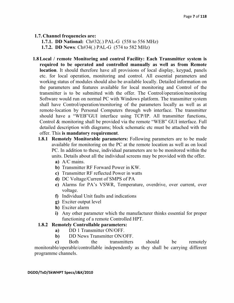
1.7. Channel frequencies are: 1.7.1. DD National: Ch#32(.) PAL-G (558 to 556 MHz) 1.7.2. DD News: Ch#34(.) PAL-G (574 to 582 MHz)
1.8 Local / remote Monitoring and control Facility: Each Transmitter system is required to be operated and controlled manually as well as from Remote location. It should therefore have all provisions of local display, keypad, panels etc. for local operation, monitoring and control. All essential parameters and working status of modules should also be available locally. Detailed information on the parameters and features available for local monitoring and Control of the transmitter is to be submitted with the offer. The Control/operation/monitoring Software would run on normal PC with Windows platform. The transmitter system shall have Control/operation/monitoring of the parameters locally as well as at remote-location by Personal Computers through web interface. The transmitter should have a “WEB”GUI interface using TCP/IP. All transmitter functions, Control & monitoring shall be provided via the remote “WEB” GUI interface. Full detailed description with diagrams; block schematic etc must be attached with the offer. This is mandatory requirement.
1.8.1 Remotely Monitorable parameters: Following parameters are to be made available for monitoring on the PC at the remote location as well as on local PC. In addition to these, individual parameters are to be monitored within the units. Details about all the individual screens may be provided with the offer.
a) A/C mains. b) Transmitter RF Forward Power in KW. c) Transmitter RF reflected Power in watts d) DC Voltage/Current of SMPS of PA e) Alarms for PA’s VSWR, Temperature, overdrive, over current, over
voltage. f) Individual Unit faults and indications g) Exciter output level h) Exciter alarm i) Any other parameter which the manufacturer thinks essential for proper
functioning of a remote Controlled HPT. 1.8.2 Remotely Controllable parameters:
a) DD 1 Transmitter ON/OFF. b) DD News Transmitter ON/OFF. c) Both the transmitters should be remotely
monitorable/operable/controllable independently as they shall be carrying different programme channels.

Page 8 of 118
DGDD/TxD/5kWHPT Specs/J&K/2010
1.9 Input, Monitoring and Measuring Equipment Rack: The equipment like IRD, 10x2 Audio-Video switcher, Waveform monitor, Colour Pattern Generator, and monitoring amplifier etc. should be installed in standard 19” wired rack(s). A Suggestive Schematic is given in Annexure II.
2 System configuration: The monitoring system of both transmitters shall have LCD display. Control circuits should be microprocessor based. Mimic RF flow diagram should be provided for diagnostic and trouble shooting of transmitter system.
3 The scope of the Supply, Installation, Testing and Commissioning (SITC) work includes the following:
3.1 SITC of 2 Nos. of 5 kW UHF Transmitters along with Input, Monitoring and Measuring equipment complete in all respects to be installed in a air-conditioned container (weather proof container having heating as well cooling facility).
3.2 SITC of Antenna System, RF feeder Cable, Combiner, Dehydrator and 7 Port Patch Panel.
3.3 SITC of Power Supply equipment including DG sets, UPS systems, AVR, AMF Panel etc.
3.4 SITC for Suitable Strengthening of existing 50 M AIR FM Tower at Rajouri as required, before installation of Antenna System and RF Feeder Cable on the tower.
3.5 SITC of power supply system. 3.6 SITC of Satellite receive equipment (PDAs, feeds, LNBCs, IRDs, Cables)
including foundation of 6.2 M PDAs. 3.7 Design and SITC (DSITC) of container as per DD specifications with sloping roof
for Transmitter and Power Supply Equipment.
4 Exciters: Exciters shall have their own DC power supply and there shall be digital
signal processing (DSP) in the exciter. It shall have facility for auto correction of non linear distortions. Exciters shall function in (1+1) configuration with necessary hardware and software control for auto changeover with suitable display system. A detailed circuit diagram must be attached with the offer to confirm the availability of DSP in the exciter.
5 Power Amplifier System:
5.1 Each power amplifier(PA) must have its own DC power supply unit, All PAs must be inter changeable at any position and to be use at any channel in the specified band of operation without change of any hardware/software in the transmitters of same make and model. All PAs shall have protection against high SWR, Over

Page 9 of 118
DGDD/TxD/5kWHPT Specs/J&K/2010
current, Over voltage and Over temperature. Visual indication for above protections should be available in each power amplifier, LDMOSFET devices shall be used in all power amplifiers. The datasheet of the LDMOS must be attached with the offer.
5.2 All PAs should be hot pluggable, Transmitter shall be capable to remain ON AIR with reduced power output without any break in service even if a number of PA/PAs have failed. All PAs shall be fully broadband for operation in UHF Band IV/V i.e.470MHz to 862MHz.
6 Cooling system: The transmitter with liquid cooling system only is acceptable. 6.1 To make the system fully reliable, all possible redundancy must be incorporated in
to the cooling system. 6.2 Full details of the cooling system with block schematic including details of coolant
must be provided with the offer. 6.3 All materials, piping, tools, liquid coolant up to double capacity required for the
transmitters, essential spares must be supplied along with the transmitter (one full quantity of coolant filled and one spare quantity of the coolant for each of the transmitters is to be provided).
6.4 Connectors of amplifiers etc shall be of self locking type so that no liquid escapes during removal or replacement of PA/Power supplies.
6.5 Outside temperatures may vary from -10o C to +50o C. Heat exchanger and liquid coolant used must be compliant with these temperature variations. There should be special provisions for satisfactory working of Heat exchangers to transfer the heat at very low temperature i.e., -10o C outside environment.
7 Upgradability to DVB-T2 Transmitter: 7.1 The offered analog transmitter should be able to be used as DTT (DVB-T2)
(Digital terrestrial transmitter adopting DVB-T2 standard) Transmitter in future with the minimum possible changes.
7.2 The offered analog transmitter should have low level diplexing (Common Amplification). Full technical details for upgradation of quoted anlog transmitter as DTT (DVB-T2) transmitter along with the financial requirement for the upgradation must be furnished with the offer separately without which tender will be considered incomplete & is liable to be rejected. This upgradation cost will however not be counted for deciding the lowest bidder. Break detail of the items must be provided in the BOM as optional items.
7.3 The broad specifications of upgraded analog transmitter to DVB-T2 DTT Transmitter are given below:
7.4 Broad Specifications of DVB-T2 Transmitter: System Parameters 7.4.1 Transmitter Power output To be specified by the Transmitter OEM

Page 10 of 118
DGDD/TxD/5kWHPT Specs/J&K/2010
(after output BPF (DVB-T2 critical mask))
7.4.2 Frequency Range Any assigned channel between 470 MHz to 862 MHz (UHF Band IV/V)
7.4.3 Bandwidth 8 MHz 7.4.4 TV standard DVB-T2, compliant to EN 302 755 7.4.5 Harmonic level (for all
harmonics) 60 dB below carrier level or better
7.4.6 Spurious emission 60 dB below carrier level or better
7.4.7 Modulation Coded orthogonal frequency division multiplex (COFDM) having all modes of modulation and parameter options as per EN 302 755
7.4.8 Inter modulation products (before filter)
<-35dB (with pre correction) at ±4.2MHz
7.4.9 Crest Factor/PAPR 13 dB Max 7.4.10 Equivalent Noise
Degradation (END) 1 dB Max
7.4.11 MER at the input of critical mask
> 33 dB
7.4.12 Shoulder Level (before filter) < - 35 dB 7.4.13 Shoulder Level (after critical
filter) According to DVB-T2 critical mask. Necessary graph to support must be provided.
8. Technical Specifications for one 5 kW Analog TV Transmitter System
S.No. Parameter Value 8.1. A.C. input Power Supply 415 V ±10%, 50Hz ± 2%
three phase 4-wire / 230V single phase & power factor >0.9.
8.2. (a)Ac power consumption of TV transmitter system at black level
(b) Ac power consumption of
To be specified by the OEM.

Page 11 of 118
DGDD/TxD/5kWHPT Specs/J&K/2010
cooling system
(c) Total power consumption of Complete TV transmitter system
8.3. Ambient Temperature(For operation/storage)
0o C to 45o C / -10o C to 50o C
8.4. Relative Humidity 90% (max) at 40oC (non condensing) 8.5. Max Altitude 3500 m above sea level 8.6. Frequency Range of
Transmitter Any assigned channel between 470MHz to 862 MHz (Band IV / V)) with facility of frequency offset by ±2/3 of line frequency
8.7. TV Standard PAL : 625 lines, CCIR - G 8.8. Carrier frequency stability ±150Hz over a period of three months
8.9. Output power of each Transmitter (Visual sync peak) At the output of band pass filter
5kW Aural Power: FA1= -13dB, FA2= -20dB, w.r.t. Visual Carrier Power
8.10. RF output impedance 50 ohms unbalanced with VSWR <1.3
8.11. Harmonic level -60 dB below carrier level
8.12. Spurious emission -60 dB below carrier level
8.13. Video input Level Sync 0.3V ±6dB, video 0.7V
8.14. Video input impedance 75 ohms unbalance (BNC) 8.15. Video input return loss > 34 dB (Upto 5 MHz) 8.16. Video Frequency response As per Table 1 8.17. Random AM Noise (100kHz to
5MHz) RMS Value: a) Unweighted continuous b) Weighted continuous c) Periodic Noise/Hum
-52dB (RMS) or better -60dB (RMS) or better -46dB (p-p) or better
Page 12 of 118
DGDD/TxD/5kWHPT Specs/J&K/2010
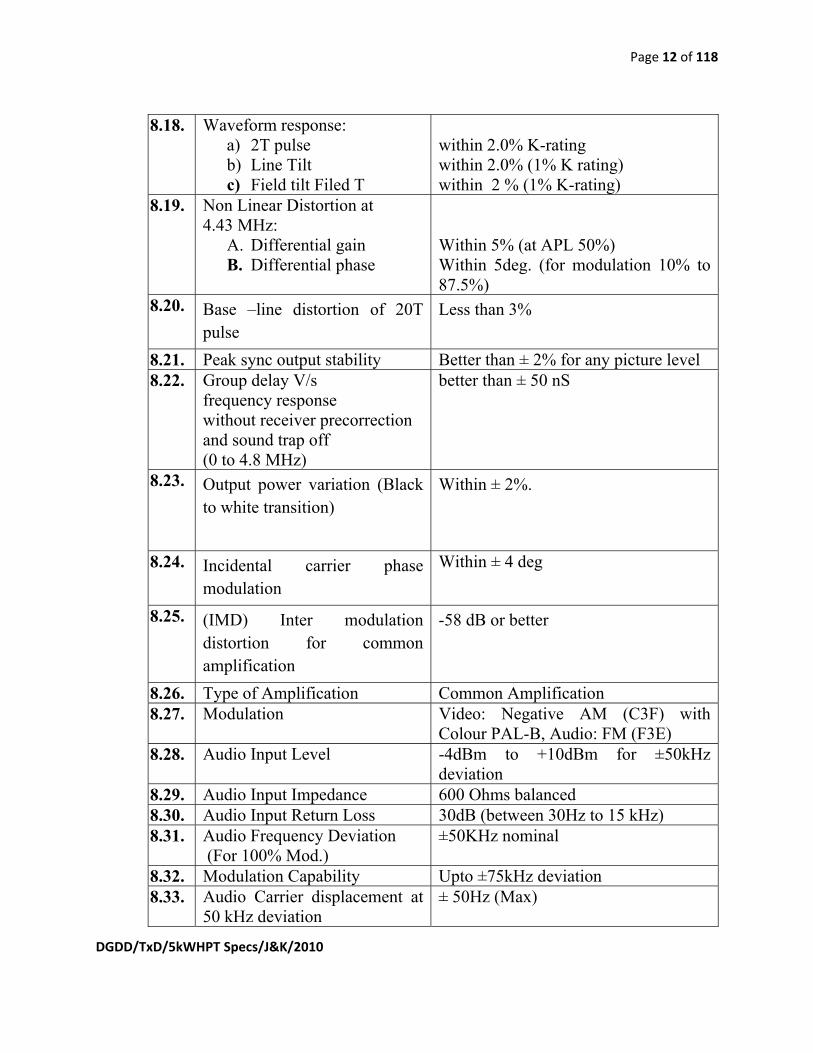
8.18. Waveform response: a) 2T pulse b) Line Tilt c) Field tilt Filed T
within 2.0% K-rating within 2.0% (1% K rating) within 2 % (1% K-rating)
8.19. Non Linear Distortion at 4.43 MHz:
A. Differential gain B. Differential phase
Within 5% (at APL 50%) Within 5deg. (for modulation 10% to 87.5%)
8.20. Base –line distortion of 20T pulse
Less than 3%
8.21. Peak sync output stability Better than ± 2% for any picture level 8.22. Group delay V/s
frequency response without receiver precorrection and sound trap off (0 to 4.8 MHz)
better than ± 50 nS
8.23. Output power variation (Black to white transition)
Within ± 2%.
8.24. Incidental carrier phase modulation
Within ± 4 deg
8.25. (IMD) Inter modulation distortion for common amplification
-58 dB or better
8.26. Type of Amplification Common Amplification 8.27. Modulation Video: Negative AM (C3F) with
Colour PAL-B, Audio: FM (F3E) 8.28. Audio Input Level -4dBm to +10dBm for ±50kHz
deviation 8.29. Audio Input Impedance 600 Ohms balanced 8.30. Audio Input Return Loss 30dB (between 30Hz to 15 kHz) 8.31. Audio Frequency Deviation
(For 100% Mod.) ±50KHz nominal
8.32. Modulation Capability Upto ±75kHz deviation 8.33. Audio Carrier displacement at
50 kHz deviation ± 50Hz (Max)

Page 13 of 118
DGDD/TxD/5kWHPT Specs/J&K/2010
8.34. AF Bandwidth 1. With pre-emphasis 2. Without pre-emphasis
30Hz to 15KHz 30Hz to 20KHz
8.35. Audio Pre-emphasis 50 microsecond 8.36. Amplitude Vs Freq. Response
for audio (with 50% modulation)
± 0.5 dB between 30Hz to 15KHz
8.37. Harmonic distortion (audio) Less than 0.5% within 30 Hz to 15KHz for 100% modulation i.e. 50KHz deviation.
8.38. FM Noise (Unweighetd) (Weighted)
Better than –60dB with respect to100% modulation -66dB or less
8.39. (a)Dimension of transmitter (L x B x H) (b) Dimension of Pump rack (L x B x H) (c) Dimension of Heat exchanger (L x B x H)
To be specified by the suppliers in meters.
8.40. (a)Weight of transmitter (b) Weight of Pump rack (c)Weight of Heat exchanger
The be specified by the suppliers in Kgs.
Table 1
Amplitude V/s frequency Response of the vision transmitter: Freq. relative to carrier in
MHz Limits (dB) maximum
Limits (dB) Minimum
-4.43 -30 - -4.43 to -1.25 -20 - -1.25 to -0.75 +0.5 -
-0.75 +0.5 -4.0 -0.5 +0.5 -1.5
0 to 1.5 +0.5 -0.5

Page 14 of 118
DGDD/TxD/5kWHPT Specs/J&K/2010
+1.5 Reference - +3.0 +0.5 -0.5 +4.43 +0.5 -0.5 +5.0 +0.5 -2.5 +5.5 -26 -
9 A pre bid conference on technical specifications and other issues shall be held on
…………….. at …… Hrs in Conference Hall, Room No. 346, Directorate General, All India Radio, New Delhi-110001, India. All prospective bidders may attend the pre bid conference to discuss their queries/suggestions. All queries/suggestions should be sent at least 2 days before pre-bid conference. No queries/suggestions shall be entertained after pre-bid conference. Amendments subsequent to the pre bid conference shall be sent to prospective tenderers, who have purchased tender document by e-mail/fax/post. Amendment shall also be posted on All India Radio website www.allindiaradio.org. It shall be tenderer’s responsibility to check for any amendments on AIR’s website before submitting their duly completed bids.
10 General Requirements for completing the offer: 10.1 Technical Literature and Manuals: All the related technical literature,
pamphlets, manuals “in English” must be submitted with the offer without which tender will be considered incomplete & is liable to be rejected. The detailed description regarding the installation manual and operation & maintenance manual is given below: 10.1.1 Installation Manual: All the views, i.e. Front, rear, top and side, of
the TV Transmitter System with dimensions are to be provided. A detailed diagram showing the cooling liquid Inlet to the transmitter and the outlet to heat exchanger system should be provided. Typical installation drawings with dimensions of Transmitter Rack(s), Pump Rack and heat exchanger are to be provided. A detailed write up in English regarding installing the TV Transmitter along with its associated equipment items should be provided. The procedure of alignment, and adjustment of various assemblies, sub- assemblies of TV Transmitter System to be described in details in the installation manual. A detailed description with all relevant circuit diagrams for the control circuit of the transmitter should be provided. Procedure for operating the transmitter on low power may be provided.
10.1.2 Operation and Maintenance Manual: All details regarding putting “ON” with the sequence of operation of the Transmitter is to be provided in the manual. The details of all electrical circuits in various stages of the Transmitter used along with their write-ups are to be

Page 15 of 118
DGDD/TxD/5kWHPT Specs/J&K/2010
provided in this manual. The various tests and measuring equipment required and essential for the routine maintenance and calibration along with the procedure for taking such measurement calibration should be provided in the manual. Technical manuals of all the items to be attached with the offer. The detailed procedure for trouble shooting of the TV Transmitter System preferably up to component level should be available in the manual. Various test fixtures and accessories required for the maintenance/ repair of the TV Transmitter System should be clearly described and detailed out in this manual. The systematic trouble shooting/ fault tree and flow diagram should be provided for diagnosis of the fault with its remedial measures in this manual. The operating manual should have description regarding various interfaces, connectors, connecting cables and accessories required for the satisfactory function of the TV Transmitter System. All such items required should be provided by the manufacturer along with the transmitter system.
10.2 ATP: 10.2.1 A copy of ATP (Acceptance Test Procedure) must be submitted by
the bidder within one month of issue of Purchase order for acceptance by Doordarshan.
10.2.2 ATP should describe the standard testing procedures and the details of test benches for carrying out measurement etc. for the offered transmitter and the antenna system. The test reports will not be treated as ATP.
10.2.3 The respective OEMs only shall prepare the ATP for their product being offered.
10.2.4 The accepted/approved ATP with or without changes shall be sent back to the bidder to be used for inspection of transmitter/antenna systems by DD Engineer(s) at respective OEM’s works before dispatch of transmitter/antenna systems.
10.2.5 The bidder has to intimate DD for inspection and testing of the offered TV Transmitter System/antenna system, at least six weeks in advance when the transmitter/antenna systems are likely to be ready for inspection. Inspection period for Transmitters/antenna will be three days each, at respective OEMs’ location.
10.3 Software: 10.3.1 One set of Copies of all softwares used in the transmitter and allied
equipment should be provided in the form of CD besides being loaded in to the system.
10.3.2 Any Future upgrade of software within five years of supply of equipment shall be made available free of cost to Doordarshan.
Page 16 of 118
DGDD/TxD/5kWHPT Specs/J&K/2010
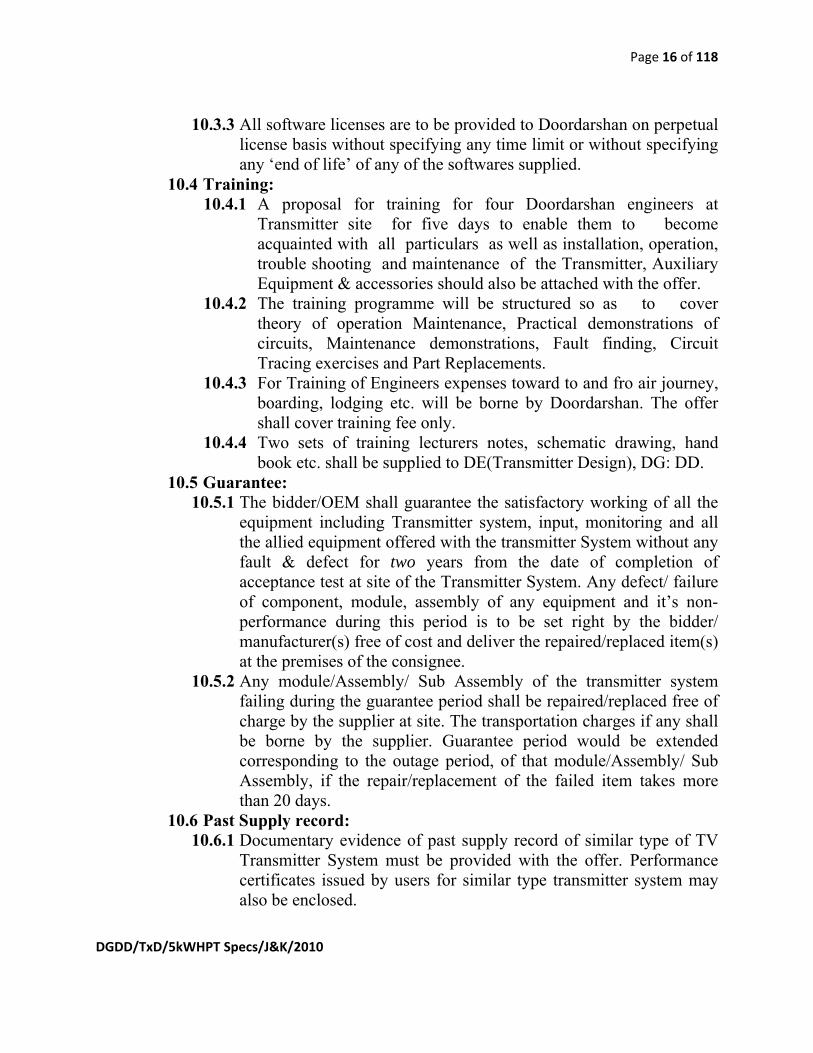
10.3.3 All software licenses are to be provided to Doordarshan on perpetual license basis without specifying any time limit or without specifying any ‘end of life’ of any of the softwares supplied.
10.4 Training: 10.4.1 A proposal for training for four Doordarshan engineers at
Transmitter site for five days to enable them to become acquainted with all particulars as well as installation, operation, trouble shooting and maintenance of the Transmitter, Auxiliary Equipment & accessories should also be attached with the offer.
10.4.2 The training programme will be structured so as to cover theory of operation Maintenance, Practical demonstrations of circuits, Maintenance demonstrations, Fault finding, Circuit Tracing exercises and Part Replacements.
10.4.3 For Training of Engineers expenses toward to and fro air journey, boarding, lodging etc. will be borne by Doordarshan. The offer shall cover training fee only.
10.4.4 Two sets of training lecturers notes, schematic drawing, hand book etc. shall be supplied to DE(Transmitter Design), DG: DD.
10.5 Guarantee: 10.5.1 The bidder/OEM shall guarantee the satisfactory working of all the
equipment including Transmitter system, input, monitoring and all the allied equipment offered with the transmitter System without any fault & defect for two years from the date of completion of acceptance test at site of the Transmitter System. Any defect/ failure of component, module, assembly of any equipment and it’s non-performance during this period is to be set right by the bidder/ manufacturer(s) free of cost and deliver the repaired/replaced item(s) at the premises of the consignee.
10.5.2 Any module/Assembly/ Sub Assembly of the transmitter system failing during the guarantee period shall be repaired/replaced free of charge by the supplier at site. The transportation charges if any shall be borne by the supplier. Guarantee period would be extended corresponding to the outage period, of that module/Assembly/ Sub Assembly, if the repair/replacement of the failed item takes more than 20 days.
10.6 Past Supply record: 10.6.1 Documentary evidence of past supply record of similar type of TV
Transmitter System must be provided with the offer. Performance certificates issued by users for similar type transmitter system may also be enclosed.

Page 17 of 118
DGDD/TxD/5kWHPT Specs/J&K/2010
10.6.2 The detail of Past Supply Record must be submitted in the following format, Doordarshan reserves the right to get performance feedback of the transmitter system from any of the user(s) as mentioned in past supply record:
Order No. with date, reference
Transmitter Type, Model and Power of transmitter
Quantity Name of the broadcaster with full postal address to whom transmitter was supplied.
Name, Telephone, Fax, Email ID of concerned personnel, purchaser, for getting feedback on transmitter performance
(1) (2) (3) (4) (5)
10.7 Experience: 10.7.1 The OEM of the transmitter system must have an experience of
manufacturing and supplying TV transmitters at least for last 10 years.
10.7.2 The OEM of the antenna system must have an experience of manufacturing and supplying broadcast antennae at least for last 10 years.
10.7.3 In case the bidder is the authorized representative, the bidder must be in the business of sales, supply and integration or turnkey execution of broadcast transmitters for last two years.
10.7.4 Documentary evidence in support of the experience as mentioned in above three paras must be attached with the offer failing which the tender will be considered incomplete and is liable to be rejected.
10.7.5 The Antenna Manufacturer must have his own test bench including test field, rotating tower, suitable receiving equipment for measuring various parameters and their analysis. Necessary supporting documents along with the details, drawings, photographs etc. of the above test bench facility must be provided with the offer.
10.8 Maintenance support/spares: 10.8.1 The minimum recommended essential spares (like modules of PA,
Power Supply Modules or any other critical spares suggested by the OEM), required to maintain the continued service of transmitter in a reliable manner, shall be quoted separately by the supplier positively.
10.8.2 The spares shall be treated as optional items and the cost of spares shall not be taken into account while deciding the lowest bidder.

Page 18 of 118
DGDD/TxD/5kWHPT Specs/J&K/2010
10.8.3 The minimum, recommended essential spares may be based on predicted rate of failure and requirement for three years.
10.8.4 The manufacturer shall also give a certificate attached with the offer to supply maintenance support and all spares during the lifetime of the TV Transmitter System. The life of the TV transmitter system should be certified by the manufacturer. This is an essential requirement. The life of transmitter should be more than Ten years.
10.8.5 The bidder must also attach with the offer the certificates to supply all spares, installed softwares and software updates for providing maintenance support during the lifetime of all the input, monitoring and all other auxiliary items/equipment offered with the transmitter system.
10.8.6 The life time of each equipment/items/allied equipment supplied is to be specified by the respective OEMs. These certificates duly signed are to be provided by the respective OEMs only on their letter heads.
10.8.7 In addition, the bidder shall provide, in the following format, the address and contact information for after-sales-support of all the equipment including all the third party bought out equipment that are to be supplied with the transmitter system as part of input, monitoring, measuring or allied equipment.
Name of Equipment with model No.
OEM After sales & support office address
Name, Telephone/ Fax/ Email of concerned personnel
Authorization by the OEM for supply and after sales support of the equipment
(1) (2) (3) (4) (5)
10.9 Local Representative/Dealer:
10.9.1 The transmitter manufacturer shall give the address of the local office /Representative/Dealer in India to facilitate interaction.

Page 19 of 118
DGDD/TxD/5kWHPT Specs/J&K/2010
10.9.2 In case any item of transmitter system requires repairs at works/factory, the same would be handed over to local office /Representative/Dealer in India, who would arrange export of the item to works/factory and re-import in India after repairs. After sales service and maintenance support of the transmitter system should be available in India through the local office /Representative/Dealer.
10.9.3 Copy of Agreement/ MoU signed in this regard between OEMs and their local representative/dealer must be submitted with the offer.
11 Information to be furnished by successful bidder:
11.1 On acceptance of the tender, the name of the accredited representative(s) of the Bidder who would be responsible for taking instructions from DG: DD, New Delhi-110001 or his authorized representative should be communicated in writing to Indenter within 15 days.
11.2 Copies of packing slips and other details should be sent separately to the consignee and also to The Director Engg. (Transmitter Design), Doordarshan Directorate New Delhi.
12 Inspection:
12.1 The inspection of the TV Transmitter System and the antenna system at the OEM’s premises before the dispatch of the transmitter system and antenna system shall be performed by DD Inspectors at respective OEMs’ works.
12.2 The bidder has to intimate DD at least six weeks in advance when the transmitter/antenna is ready for inspection.
12.3 The approved ATPs shall be used for testing the transmitter/antenna.
12.4 In case pre dispatch inspection at the Manufacturers’ facility is not carried out by DD engineer(s) due to any reasons, Copies of factory test reports & test data along with guarantee certificates shall be furnished by the OEM.
12.5 The expenditure for DD inspectors on To & fro airfare, per Diem allowances, lodging, boarding charges etc. shall be borne by Doordarshan.

Page 20 of 118
DGDD/TxD/5kWHPT Specs/J&K/2010
The bidder in his offer shall cover inspection fees only. The inspection fee if any shall be included in the main BOM for deciding the lowest offer.
12.6 . All other associated equipment, items and accessories will be accepted on the basis of Original Equipment Manufacture’s (OEM) Test Certificates (as per DD Specification) duly signed and stamped on the letter head of the OEM, failing which Original Equipment Manufacturer’s (OEM’s) Test Certificates will be considered incomplete and equipment offered by the firm is liable to be rejected.
13 Installation, testing and commissioning at site:
13.1 The transmitter and antenna system shall be supplied, installed and tested by the supplier/OEMs as per the specifications of Doordarshan. Thereafter, commissioning of the complete system will be carried out, in the presence of DD representative, by the supplier/OEMs’ representative engineer(s). The supplier/OEMs will intimate Doordarshan at least 20 days in advance, when the system has been installed, tested and is ready for acceptance measurements, testing and commissioning.
13.2 For this purpose complete Test Procedure will be prepared by the supplier/OEM(s). The test procedures will indicate full details of test set up for measuring / testing required during the Performance Measurement/ Acceptance Testing at the site. All equipment required for measurements and testing of Transmitter System, other auxiliary equipment and antenna system has to be arranged by the bidder at the site.
13.3 Installation, testing and commissioning of the transmitter and antenna system as per specification shall be done under the supervision of Qualified Engineers of OEMs duly trained and certified by OEMs of main equipment i.e. transmitter and antenna at site.
14 BOM:
14.1 A detailed, complete Bill of material (deliverables) shall be attached with the technical bid leaving price column blank. This Bill of material (BOM) shall be exactly in the same format as in the price bid minus the price.
Page 21 of 118
DGDD/TxD/5kWHPT Specs/J&K/2010
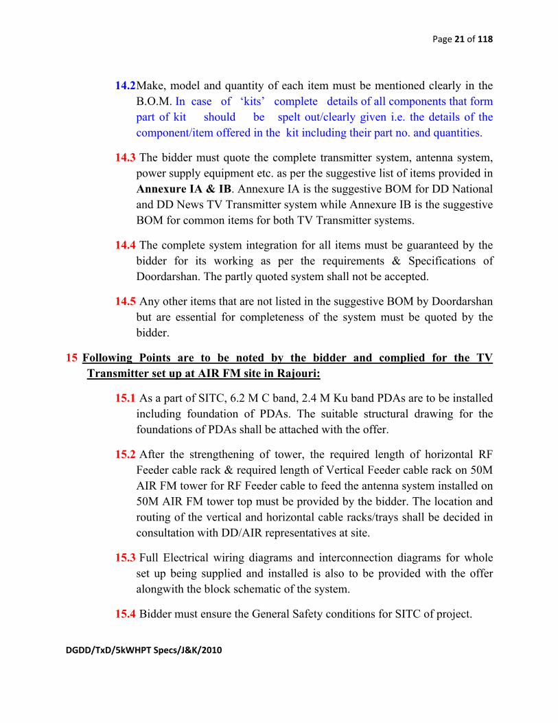
14.2 Make, model and quantity of each item must be mentioned clearly in the B.O.M. In case of ‘kits’ complete details of all components that form part of kit should be spelt out/clearly given i.e. the details of the component/item offered in the kit including their part no. and quantities.
14.3 The bidder must quote the complete transmitter system, antenna system, power supply equipment etc. as per the suggestive list of items provided in Annexure IA & IB. Annexure IA is the suggestive BOM for DD National and DD News TV Transmitter system while Annexure IB is the suggestive BOM for common items for both TV Transmitter systems.
14.4 The complete system integration for all items must be guaranteed by the bidder for its working as per the requirements & Specifications of Doordarshan. The partly quoted system shall not be accepted.
14.5 Any other items that are not listed in the suggestive BOM by Doordarshan but are essential for completeness of the system must be quoted by the bidder.
15 Following Points are to be noted by the bidder and complied for the TV Transmitter set up at AIR FM site in Rajouri:
15.1 As a part of SITC, 6.2 M C band, 2.4 M Ku band PDAs are to be installed including foundation of PDAs. The suitable structural drawing for the foundations of PDAs shall be attached with the offer.
15.2 After the strengthening of tower, the required length of horizontal RF Feeder cable rack & required length of Vertical Feeder cable rack on 50M AIR FM tower for RF Feeder cable to feed the antenna system installed on 50M AIR FM tower top must be provided by the bidder. The location and routing of the vertical and horizontal cable racks/trays shall be decided in consultation with DD/AIR representatives at site.
15.3 Full Electrical wiring diagrams and interconnection diagrams for whole set up being supplied and installed is also to be provided with the offer alongwith the block schematic of the system.
15.4 Bidder must ensure the General Safety conditions for SITC of project.

Page 22 of 118
DGDD/TxD/5kWHPT Specs/J&K/2010
15.5 Bidder shall make good all damages to the purchaser’s building, property, equipment etc. how-so-ever arising while doing strengthening of the AIR FM tower, construction PDA foundations and carrying out the entire SITC work throughout the period of execution of the SITC Project at AIR FM Rajouri site.
15.6 The Bidder shall indemnify and hold harmless the purchaser against any claims in respect of damages to building, property situated nearby, not belonging to the purchaser, how-so-ever arising while doing strengtheing of the AIR FM tower, construction PDA foundations and carrying out the entire SITC work throughout the period of execution of the SITC Project at site.
15.7 The Bidder shall indemnify and hold harmless the purchaser against claims in respect to injury any mishap to any person how-so-ever arising while doing strengthening of the AIR FM tower, construction PDA foundations and carrying out the entire SITC work throughout the period of execution of the SITC Project.
15.8 The Bidder shall discharge all obligations under the Indian workmen’s compensation act, any local/state laws and regulations in so far as it affects the workmen in his employment during the full period of the execution of the entire SITC Project.
15.9 The Tenderer should conform to all local State laws/Central laws and regulations amended up to date concerning labour and their employment as applicable. The insurance etc of the labourers shall be the responsibility of the Tenderer including any kind of pre /post action and consequences relating to above insurance etc.
15.10 Prior approval of the purchaser, in writing, shall be obtained, if the bidder desires to sublet or assign any section of the work associated with the fabrication, work related with strengthening of tower etc to any other agency. Such permission or consent shall not, however discharge the bidder from his liabilities in this contract or any part thereof.
15.11 The bidder shall make his own arrangements for power supply, water and the safe custody of materials at site for the entire SITC project.

Page 23 of 118
DGDD/TxD/5kWHPT Specs/J&K/2010
15.12 The bidder shall make his own arrangement for employing labour, skilled & unskilled, and shall make his own arrangement for providing accommodation for his workmen at site or elsewhere during the entire SITC Project.
15.13 After completion of SETC work the Tenderer shall remove dust, dirt, debris and leave the building/ premises in a clean condition.
16 Compliance Statement: A para by para compliance statements in the format given below, with page numbers of the tender document describing DD specifications, of the manufacturers quoted items and remarks, should be attached with the offer by the manufacturers only on their letter head duly signed but not by the local agent or local representative of the manufacturer with the relevant supporting literature, manuals etc. The bidder shall countersign all the compliance statements. The compliance statements should be provided for all the technical as well as general specifications for all the paras listed above and all the annexures in these specifications. This is a mandatory and essential requirement. Mere signing of DD Specs sheets shall not be treated as compliance statement. Any offer without the compliance statements for all paras as detailed above as well as compliance statement in respect of the items/equipment, specifications, Annexures shall be rejected in the first instance without making any reference to the bidder. The entire technical bid shall be page numbered and each page shall be signed by the bidder.
Para No. Of DD Spec.
DD spec value & Details
Quoted items value and details, as per the data sheet of offered system.
The page no. of the offer/Technical bid, where the information/supporting document is available.
Compliance OR Deviation
Remarks
(1) (2) (3) (4) (5) (6)

Page 24 of 118
DGDD/TxD/5kWHPT Specs/J&K/2010
ANNEXURE-I-A (SUGGESTIVE BILL OF MATERIAL)
SUGGESTIVE LIST OF MATERIAL FOR 5KW, UHF, DD-NATIONAL AND DD- NEWS, Band IV/V Analog TV TRANSMITTER SYSTEMS & THEIR STATION ITEMS
S. NO. DESCRIPTION MAKE/MODEL QTY. 1 5 KW, UHF, BAND IV/V, Analog (common amplification
type), upgradable to DVB-T2, Transmitter System as per DD specifications with all items required to complete the entire system, including: (a) TRPA extender module. (b) Dual Exciter system with DSP. (c) Liquid pump assembly including all pipes and accessories, alongwith spare coolant and coolant filling arrangement. (d) Heat exchanger unit to work for temperature range -10ºC to 50 ºC. (e) Transmitter control unit with necessary software. (f) Power amplifiers with inbuilt power supply (g) All items of transmitter to complete it as a full system. (h) Installation, Maintenance & Operational Manuals & test data (i) Transmitter output 3⅛”EIA unflange. (k) Any other item(s) to complete the transmitter system
2SETS complete in all respect
2 3 Phase unbalanced AVR and Power Distribution Panel (with phase sequence reversal sensing and protection circuit) and Surge suppressor in Air cooled construction as per DD Specifications given in Annexure I-1 (One AVR each with one Transmitter)
2 Nos.
3 OUTPUT COAXIAL EQUIPMENT 3.1 Broadcast Power Monitor, UHF Band IV/V, with 3 ⅛” EIA
unflanged line section and suitable elements for measurement as per DD Specifications given in Annexure I-2
2No
4 INDOOR COAXIAL FEEDER COPPER COMPONENTS ONLY (AS PER THE ACTUAL INSTALLATION REQUIREMENT IN THE EQUIPMENT CONTAINER) as per DD Specifications given in Annexure I-3
2 Lots (one for each transmitter)
4.1 3 ⅛” EIA Straight Transmission Line Copper Sections (VSWR<1.05) Sections of length 5 to 6 Meters may be used to
As per the actual installation

Page 25 of 118
DGDD/TxD/5kWHPT Specs/J&K/2010
minimize coupling joints. requirement 4.2 3 ⅛” EIA 90 DEG. ELBOW (VSWR<1.05)
As per the actual installation requirement
4.3 Straight Coupling 3 ⅛” EIA (with inner and outer conductor and two nos of hose clamps for each Straight coupling) (VSWR<1.05)
As per the actual installation requirement
4.4 Fixed Hanger Assy 3 ⅛” EIA (VSWR<1.05)
As per the actual installation requirement
4.5 3 ⅛” EIA Flange to Non flange adopter (VSWR<1.05)
As per the actual installation requirement
5 INPUT & MONITORING EQUIPMENT TO BE PROVIDED WITH EACH 5 kW TRANSMITTER:
5.1 VIDEO EQUALISING DA as per DD Specifications given in Annexure I-4-II, comprising of:
2 sets (one for each transmitter)
5.1.1 Video equalizing amplifier with clamp
2 Nos. (one for each transmitter)
5.1.2 Audio Video mounting frame, 2RU, looping inputs with power supply and card.
2 Nos(one for each transmitter)
5.1.3 Redundant power supply
2 Nos (one for each transmitter)
5.2 Audio stereo Monitoring Amplifier 8 W with compatible loud speaker as per DD Specifications given in Annexure I-4-VI
2Sets. (one for each transmitter)
5.3 Audio Distribution Amplifier housed in a suitable frame with redundant power supply & extender card, as per DD Specifications given in Annexure I-4-VII:
2 sets (one for each transmitter)
5.3.1 Stereo analog audio distribution amplifier (4 stereo balanced outputs)
2 Nos. (one for each transmitter)
5.3.2 Audio DA mounting frame, including plug in audio connectors, one power supply and power cord.
2Nos. (one for each transmitter)
5.4 Audio Processor as per DD Specifications given in Annexure I-4-VIII
2 Nos. (one for each transmitter)
5.5 Amplispeaker as per DD Specifications given in Annexure I-19
2 Nos. (one for each transmitter)
5.6 AUDIO VIDEO SWITCHER as per DD Specifications given in Annexure I-4-III
5.6.1 10X2 Audio, Video married switcher with redundant power supply and extender card consisting of:
2 Sets

Page 26 of 118
DGDD/TxD/5kWHPT Specs/J&K/2010
5.6.2 Audio video + Stereo Audio, Router switcher with internal power supply and extender logic card.
5.6.3 Redundant External AC power supply for 2RU frame
5.6.4 local programmable push button
5.6.5 Mounting tray for external power supply
6 VIDEO MONITORING SYSTEM 6.1 WAVEFORM MONITOR as per DD Specifications given in
Annexure I- 5-I (PAL 625/50 waveform monitor) 4Nos. (two for each transmitter)
6.2 26” LCD TV Receiver with VHF/UHF PAL-G Tuner, AV input facility (Only Reputed Brand like Sony/Panasonic/Hitachi/Samsung/LG/JVC is to be quoted)
4Nos. (two for each transmitter)
6.3 29” LCD TV Receiver with VHF/UHF PAL-G Tuner, AV input facility, Yagi antenna and twin RF cable for off Air RF Monitoring (Only Reputed Brand like Sony/Panasonic/Hitachi/Samsung/LG/JVC is to be quoted)
2 sets. (one for each transmitter)
6.4 VU Meter Assy, with Power Supply Unit etc complete as per DD Specifications given in Annexure I-5-II
2 Nos. (one for each transmitter)
7 INSTALLATION MATERIAL: Miscellaneous installation material like coaxial cables, connectors, PTFE cables, RF Cables, 75 ohm connectors, 50 ohm connectors, power cables, flexible cables, etc. as per DD Specifications given in Annexure I-6
2 Lots as per requirement at site for two transmitters.
8 ANY OTHER ITEMS FOR COMPLETING THE SYSTEM (If any, Breakup Detail must be given)
1Set
9 Computer with 1KVA UPS and Printer-Laserjet as per DD Specifications given in Annexure I-7
4 sets (Two with each transmitter)

Page 27 of 118
DGDD/TxD/5kWHPT Specs/J&K/2010
ANNEXURE-I-B
SUGGESTIVE LIST OF MATERIAL OF COMMON ITEMS FOR 5KW, UHF, Band IV/V DD NATIONAL & FOR 5KW, UHF, Band IV/V DD NEWS, ANALOG TV TRANSMITTER SYSTEM & STATION ITEMS
SL. NO. DESCRIPTION MAKE/MODEL QTY.
1 DUMMY LOAD - Forced air cooled, 10 KW RMS power, UHF Band IV/V, 50 OHMS, 3 ⅛” EIA UNFLANGED CONNECTOR, Input 230VAC as per DD Specifications given in Annexure I-8
1No
2 MEASURING EQUIPMENT 2.1 Colour Test Pattern and Tone Generator as per DD
Specifications given in Annexure I-9-I 1Set
2.2 T.V. Analyzer/Demodulator as per DD Specifications given in Annexure I-9-II
1No
2.3 Digital Storage Oscilloscope,100MHz, 2channel (with user & service manuals and standard accessories like one power cord, two nos. of passive probes, certificate of calibration etc.) as per DD Specifications given in Annexure I-9-III
1No
3 MISC ITEMS FOR MON. & MAINTENANCE 3.1 RF Power Meter With Power Sensors as per DD specifications
given in Annexure I-20 1No
3.2 STEP ATTENUATOR (0-110dB) as per DD Specifications given in Annexure I-10-I
1No
3.3 ATTENUATOR 3dB (N type) as per DD Specifications given in Annexure I-10-II
1No
3.4 ATTENUATOR 6dB (N type) as per DD Specifications given in Annexure I-10-II
1No
3.5 ATTENUATOR 12dB (N type) as per DD Specifications given in Annexure I-10-II
1No
3.6 REDUCER 3 ⅛" unflanged to N Female(VSWR<1.05) as per DD Specifications given in Annexure I-3
3.7 REDUCER 3 ⅛" unflanged to 1 5/8” unflanged (VSWR<1.05) as per DD Specifications given in Annexure I-3
3.8 REDUCER 1 ⅝" unflanged to N Female(VSWR<1.05) as per DD Specifications given in Annexure I-3
4 TECHNICAL MANNUALS of all equipments provided as per BOM.
Total 5 Sets

Page 28 of 118
DGDD/TxD/5kWHPT Specs/J&K/2010
One sets of all manuals per order for DGDD. Two sets of all manuals for zonal office per order. Two sets of all manuals for the station.
5 ANTENNA SYSTEM as per DD Specifications given in Annexure I-11-I
5.1 10 KW, Band IV/V UHF Super turnstile, Omni directional, Broadband antenna system.
1Set Complete
5.2.1 Antenna interface for mounting the antenna on top of existing AIR FM tower.
1Set Complete
5.2.2 Horizontal cable rack and a vertical cable rack as per the actual requirement a site.
1 Set
5.2.3 Lightening Protection & Aviation Light 1 Set
5.3 Automatic dehydrator system with tubing and sealing compound for joints etc. as per DD Specifications given in Annexure I-11-III
1Set Complete
5.4 2X5 KW, 2 Channel Constant Impedance UHF Combiner as per DD Specifications given in Annexure I-11-IV
1No
5.5 3⅛” EIA Flange to Non Flange Adapter (VSWR<1.05dB) 1No
5.6 All hardware items including sealing compound with breakup of item wise details.
1Set Complete
5.7 Any other item for completeness of antenna system. 1Set Complete
6 Seven Port Patch Panel as per DD Specifications given in Annexure I-12
1Set Complete
7 RF FEEDER CABLE - (single length) as per DD Specifications given in Annexure I-13
85 meter length
7.1 Cable 3⅛”/4” including drum charges 1No
7.2 Connector 3⅛”/4” EIA Flange Gas barrier flange 1No
7.3 Connector 3⅛”/4” EIA Flange Gas Pass Flange 1No
7.4 Coupling element for 3⅛”/4” 2Nos
7.5 Grounding kit pre-formed copper strap 2Nos
7.6 Wall gland, Single entry 1No
7.7 Hoisting stocking as per the OEMs Single specified value Depending

Page 29 of 118
DGDD/TxD/5kWHPT Specs/J&K/2010
on the length of cable
7.8 Cable Clamps (To be fixed 1 M apart) (see notes below BOM) 1 lot
7.9 Cable Trays/Racks (a) Horizontal (b) Vertical. (see notes below BOM)
1 set
7.10 Any other item required to complete the system 1Set
8 C BAND/KU BAND SATELLITE RECEIVE EQUIPMENT
8.1 6.2 Mtr C-Band solid type PDA system with de-icing kit 100% full surface including dual port motorized feed and necessary mounting accessories. as per DD Specifications given in Annexure I-14-II and IV
2Sets
8.2 C-Band LNBC units with de-icing kit . as per DD Specifications given in Annexure I-14-VI
4Nos (2 Nos. with each 6.2m PDA)
8.3 Low loss Rf Cable in the denomination of 50m & 25m and necessary connectors as per DD Specifications given in Annexure I-14-III
2 x 75 m
8.4 Professional IRD unit for C band & Ku band feed operating with stand by facility as per DD Specifications given in Annexure I-14-I
4Nos
8.5 2.4 Mtr Ku-Band dish antenna with Feed and necessary mounting accessories (with slanting shed for snow/rain protection) as per DD Specifications given in Annexure I-14-IV
1 Set
8.6 Ku-Band LNBC units as per DD Specifications given in Annexure I-14-VII
1 No.
8.7 Low loss RF Cable for Ku band as per DD Specifications given in Annexure I-14-III
25Mtr
9 DG SYSTEM OPERATING IN (1+1) STANDBY MODE as per DD Specifications given in Annexure I-15
9.1 DG Engine + Alternator 80KVA 2Nos
9.2 AMF Panel 1No
9.3 Power cable. 2X25Mtrs
Page 30 of 118
DGDD/TxD/5kWHPT Specs/J&K/2010
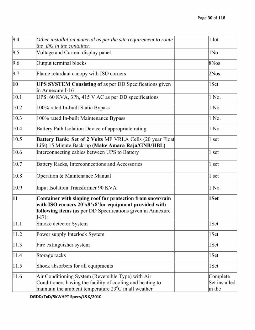
9.4 Other installation material as per the site requirement to route the DG in the container.
1 lot
9.5 Voltage and Current display panel 1No
9.6 Output terminal blocks 8Nos
9.7 Flame retardant canopy with ISO corners 2Nos
10 UPS SYSTEM Consisting of as per DD Specifications given in Annexure I-16
1Set
10.1 UPS: 60 KVA, 3Ph, 415 V AC as per DD specifications 1 No.
10.2 100% rated In-built Static Bypass 1 No.
10.3 100% rated In-built Maintenance Bypass 1 No.
10.4 Battery Path Isolation Device of appropriate rating 1 No.
10.5 Battery Bank: Set of 2 Volts MF VRLA Cells (20 year Float Life) 15 Minute Back-up (Make Amara Raja/GNB/HBL)
1 set
10.6 Interconnecting cables between UPS to Battery 1 set
10.7 Battery Racks, Interconnections and Accessories 1 set
10.8 Operation & Maintenance Manual 1 set
10.9 Input Isolation Transformer 90 KVA 1 No.
11 Container with sloping roof for protection from snow/rain with ISO corners 20’x8’x8’for equipment provided with following items (as per DD Specifications given in Annexure I-I7):
1Set
11.1 Smoke detector System 1Set
11.2 Power supply Interlock System 1Set
11.3 Fire extinguisher system 1Set
11.4 Storage racks 1Set
11.5 Shock absorbers for all equipments 1Set
11.6 Air Conditioning System (Reversible Type) with Air Conditioners having the facility of cooling and heating to maintain the ambient temperature 23oC in all weather
Complete Set installed in the
Page 31 of 118
DGDD/TxD/5kWHPT Specs/J&K/2010
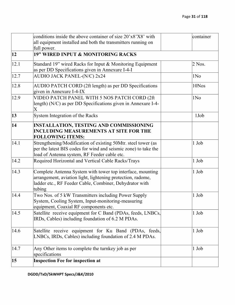
conditions inside the above container of size 20’x8’X8’ with all equipment installed and both the transmitters running on full power.
container
12 19” WIRED INPUT & MONITORING RACKS
12.1 Standard 19” wired Racks for Input & Monitoring Equipment as per DD Specifications given in Annexure I-4-I
2 Nos.
12.7 AUDIO JACK PANEL-(N/C) 2x24 1No
12.8 AUDIO PATCH CORD (2ft length) as per DD Specifications given in Annexure I-4-IX
10Nos
12.9 VIDEO PATCH PANEL WITH 5 NOS PATCH CORD (2ft length) (N/C) as per DD Specifications given in Annexure I-4-X
1No
13 System Integration of the Racks 1Job
14 INSTALLATION, TESTING AND COMMISSIONING INCLUDING MEASUREMENTS AT SITE FOR THE FOLLOWING ITEMS:
14.1 Strengthening/Modification of existing 50Mtr. steel tower (as per the latest BIS codes for wind and seismic zone) to take the load of Antenna system, RF Feeder cable etc.
1 Job
14.2 Required Horizontal and Vertical Cable Racks/Trays 1 Job
14.3 Complete Antenna System with tower top interface, mounting arrangement, aviation light, lightening protection, radome, ladder etc., RF Feeder Cable, Combiner, Dehydrator with tubing
1 Job
14.4 Two Nos. of 5 kW Transmitters including Power Supply System, Cooling System, Input-monitoring-measuring equipment, Coaxial RF components etc.
1 Job
14.5 Satellite receive equipment for C Band (PDAs, feeds, LNBCs, IRDs, Cables) including foundation of 6.2 M PDAs.
1 Job
14.6 Satellite receive equipment for Ku Band (PDAs, feeds, LNBCs, IRDs, Cables) including foundation of 2.4 M PDAs.
1 Job
14.7 Any Other items to complete the turnkey job as per specifications
1 Job
15 Inspection Fee for inspection at

Page 32 of 118
DGDD/TxD/5kWHPT Specs/J&K/2010
1) Transmitter OEM’s works
2) Antenna OEM’s works
1 Job
1 Job
16 Miscellaneous items
16.1 Audio Analyzer as per DD Specifications given in Annexure I-18
1No
17 Optional Items: 1) Minimum recommended essential spares as per DD
specs Para 10.8. The detail Breakup is to be provided in BOM by the bidder
2) Items required for upgradability to DVB-T2 (break up detail to be given)
1Lot
1 Lot
18 Training (Fee Only) for training at Transmitter site 1 Lot
Notes:
1. For ascertaining the lowest bidder the cost of 50M for Vertical Cable Racks, 20M horizontal Cable Trays and corresponding No. of cable clamps will be considered. However, the payment will be made on the basis of actual measurement of Vertical Cable Racks, Horizontal Cable trays and clamps erected actually at Rajouri site.
2. Items in the BOM are on SITC basis.

Page 33 of 118
DGDD/TxD/5kWHPT Specs/J&K/2010
Annexure I-1 Specifications of 50 KVA AVR and Power Distribution Panel:
INTRODUCTION: a. Servo Controlled Automatic Voltage Regulator (AVR) is to be used in TV
Transmitters and with other transmission equipment so that these sensitive equipment are protected from low voltage / high voltage and power supply fluctuations and surges.
b. The AVR should be rugged, reliable and stable for continuous operation. c. It should be naturally air cool type housed in one steel cubicle and hook at
the top for lifting. d. It should be from reputed manufacturer who are ISO 9001/ ISO 14001
certified. TECHNICAL SPECIFICATIONS: S. N. Parameter Value 2 Inputs 2.1 Nominal voltage 400 V, 3 Phase 2.2 Range 340 V to 440 V 2.3 Frequency 48 to 52 Hz 2.4 Waveform Sinusoidal 3 Outputs 3.1 Nominal voltagePhase 400 R.M.S. + 1.0%, 3 Phase 3.2 Settability 400 V to 410 V R.M.S. 3.3 Load regulation + 1.0% 3.4 Line regulation + 1.0% 3.5 Capacity 50 KVA 3.5 Waveform Sinusoidal 4 Efficiency > 95% at full load, unity power
factor and at minimum input voltage
5 Correction speed > 30 V/Second. Phase to phase. 5.1 Switch on delay with timer and
contactor 0 to 60 seconds.
6 Protections 6.1 Overload capacity 25% for half an hour. 6.2 Output under voltage
380V Disconnecting the load through a contactor with alarm bell.
6.3 Over voltage 430 V, Disconnecting the load through a contactor with alarm bell.
6.4 Over load tripping Disconnecting the load through a

Page 34 of 118
DGDD/TxD/5kWHPT Specs/J&K/2010
contactor with alarm bell. 6.5 Power factor effect Nil 6.6 Waveform distortion Less than 1% at full load 6.7 Line noise suppression (for control
circuit only) Line noise to be suppressed by at least 30dB for frequency range 10 MHz to 250 MHz
7 Metering (a)Analog or digital voltmeter to be provided to read input & output R.M.S. Voltages of each phase selected by selector switch. (b)Analog or Digital Ammeter to be provided to read current of each phase selected by selector switch.
8 Indications (a) LEDs for indicating (i) Input on (ii) Out put on. (b) LED for indication of input power (i) LED for indicating low input. (ii) LED for indicating of input OK. (iii) LED for indication of high input.
9 Controls (a) Output On-Off through MCCB. (b) Auto-Manual switch selection. (c) Raise/lower the output voltage in manual mode. (d) Manual By pass in case of Malfunction.
11 Input/ Output terminations (a)Suitable input & output terminations should be provided. These terminals along with other distribution board output terminals shall be provided with acrylic sheet, so that these terminals are not accessible inadvertently. (b)Earthing terminal is to be provided.
12 Weight & Dimensions (LxBxH) To be specified by the vendor.

Page 35 of 118
DGDD/TxD/5kWHPT Specs/J&K/2010
13 Environmental specifications 13.1 Ambient temperature range 0o C to + 45o C (operative) 13.2 Storage temperature range -10o C to + 50o C. 13.3 Relative Humidity 95% at +40o C. 13.4 Type of cooling Natural air cooling 14 Notes: 14.1 Derating factor (adequate) should be applied to critical components while
designing to improve life expectancy. 14.2 All the transformers and chokes must be varnish impregnated. 14.3 All the components used should be of reputed make. 14.4 PCB should be of glass epoxy material and heavy components & high
power dissipating components like transformers, chokes, high power transformers should not be mounted directly on the PCB.
14.5 AVR should be subjected to 100 hrs. Heat Run Test at max. load under normal ambient temperature condition.
14.6 AVR should be compatible & according to latest National and International standards on safety & EMC. Standards followed should be stated.
15 Guarantee: Two years from the date of receipt of equipment. 15.1 Past supply record of manufacturer in supplying similar capacity AVR to
other organization may be attached.

Page 36 of 118
DGDD/TxD/5kWHPT Specs/J&K/2010
Annexure I-2 SPECIFICATIONS OF 10KW BROADCAST POWER MONITOR (THROUGH LINE POWER METER): 1. Introduction: 1.1 Broadcast Power Monitor, UHF Band IV/V, with 3 ⅛” EIA unflanged line section and suitable elements for measurement of Max Forward power of 5 kW and reflected power of 0.5 KW, VSWR, Return Loss etc. 1.2 Ethernet & RS 232 enabled- Remote monitoring, control & instant alarm alert with 50 feet of cable to connect RS 232 and serial port between monitoring unit and line section, and serial interface cable. 1.3 Data logging capabilities – System trends and anomalies before failure. 1.4 Integral RF Test Port facility. 1.5 Frequency / Channel field configurable.
3. Technical specifications: S.No. Description
Technical Specification Remarks with
Technical Data/Schematic drawings Etc.
a) Accuracy ±5% of reading b) Connector 3⅛” EIA UnFlange c) Frequency Range 470 to 862 MHz d) VSWR < 1.10:1
e) Impedance(Nominal) 50 Ohm Nominal f) Alarms No/Low Forward power,
High forward power, VSWR
g) AC Power Single Phase, 230 volts(rms) + 10%, 50 Hz + 4%
h) Temperature of Storage
-30ºC to 50ºC
i) Temperature of Operation
0ºC to 45ºC
j) Humidity 95% NC k) Max Altitude 3500 Meter. l) Display Broadcast power
monitor

Page 37 of 118
DGDD/TxD/5kWHPT Specs/J&K/2010
m) Coupler Directivity 28dB minimum n) Dimensions:
(Length x Width x Depth)
To be specified by the bidder
o) Weight To be specified by the bidder

Page 38 of 118
DGDD/TxD/5kWHPT Specs/J&K/2010
Annexure I-3 SPECIFICATIONS OF INDOOR COAXIAL FEEDER CU COMPONENTS: 1. Introduction: 1.1 All the indoor coaxial feeder components must be of high quality copper, used for broadcasting system for a good transmission performance. 1.2 The VSWR of all coaxial feeder components must be less than 1.05. 1.3 There should be a firm grip between various coaxial feeder components. 1.4 All the components should be capable of handling the power supplied output of the transmitter. 1.5 Spacers must be used at a suitable length between inner and outer conductor.

Page 39 of 118
DGDD/TxD/5kWHPT Specs/J&K/2010
Annexure I-4 Specifications of Input, Monitoring equipment and Racks:
I. Specifications of Standard 19” Rack: i) The Stereo/mono audio and video programme input and monitoring rack should be suitable for: Feeding stereo/mono audio and video programmes to TV transmitters, & ii) Metering/monitoring of different programme input sources as well as signal at intermediate points in the audio/video chain and also detected signals. Detailed specifications of rack and individual equipment are given below. 1.0 GENERAL DETAILS: 1.1 Complete equipment, wiring and other details are to be worked out by the bidder. The details of equipment to be installed in this rack by the bidder is to be provided. 1.2 All audio/video lines from the Jacks & Equipments are to be connected to a terminal block to be located near the bottom of the rack for external feeding of cables by the indentor. All the equipment are to be properly earthed with the existing equipment earthing system in the transmitter hall. 1.3 RFI/EMI filter should be provided at mains input of the rack as per relevant provisions of FCC rules and regulations, or equivalent standards for effective rejection of the interference from the high power transmitters operating in the premises. These racks will be used in High Power Transmitter halls i.e. the rack with full complement of equipment as to operate in a high RF field. As such all the specifications of the individual equipment as well as the full chain, are to remain valid in high RF fields. 2.0 EQUIPMENT RACK: The standard 19” rack will have various equipment. The frame of the rack should be of high quality extruded aluminium or high grade steel material as per relevant material codes. The aluminium profiles should be either anodized or powder coated and the steel parts should be enameled to give pleasing and aesthetic look and superior and long lasting paint finish. The rack is to be of sturdy design. The width should be suitable for mounting of standard 19” equipment. Doors should be provided on the rear side and should have louvers and exhaust fan to facilitate proper ventilation. The overall size of rack should be 2000 (H) x 545 (W) x 600 (D) mm. 2.1 Input/Output Isolation : 90 dB 2.2 Input/Input Isolation : 90 dB
II. SPECIFICATIONS OF VIDEO EQUALIZING DISTRIBUTION
AMPLIFIER: 1. The system should be high-performance, having high reliability of professional quality, analog video equalizing distribution amplifier. 2. It should be have high quality mounting frame for mounting it in standard 19” rack.

Page 40 of 118
DGDD/TxD/5kWHPT Specs/J&K/2010
3. It should be capable of amplifying composite and component analog PAL signals, with or without sync and subcarrier signal. 4. The amplifier must have adjustable gain in the range ± 3dB. 5. The amplifier should have at least 8 outputs and one differential input. 6. It should have redundant power supply. 7. Technical Parameters-
Srl. No. Description Parameters 1. Power supply 230VAC±10%,
50Hz. 2. Operating Temperature 0ºC to 45ºC 3. Input level 1 Vp-p nominal 4. Input Impedance 75Ω 5. Input coupling DC 6. CMRR >65 7. Input Return loss >45dB 8. Output Isolation >40dB 9. Frequency Response ±0.05dB (DC to
10MHz) 10. Equalizing Response ±0.05dB (DC to
5MHz) 13. S/N ratio >70dB
III. SPECIFICATIONS OF VIDEO AUDIO SWITCHER 1. The Video Audio switchers should consist of a video switching module & audio
switching module with a Control logic board for audio to follow video operation with basic configuration of 10 inputs and 2 outputs (10x2).
2. Buttons per cross point Control lines should be available to permit Control from front panel through illuminating momentary push button.
3. Switching should be selectable between instantaneous (non vertical intervals) or as vertical interval reference.
4. The audio, video and power supply connection should be on the back side of the unit. The switcher should have following technical specifications.
S. No.
Description Specification
1. Standard PAL colour standard

Page 41 of 118
DGDD/TxD/5kWHPT Specs/J&K/2010
2.0 Video inputs 2.1 No. Of inputs 10 Nos. with loop through facility 2.2 Input signal
level 1V p-p nominal (CCVS)
2.3 Input impedance
High impedance for loop through inputs, terminable into 75 Ohms through termination plug.
2.4 Return loss Better than 40dB unto 5 MHz, across 75 Ohms 3.0 Video outputs 3.1 No. of outputs a) 2 (Two) buffered output
b) 2 for monitor bus 3.2 Output signal
level 1V p-p nominal (CCVS)
3.3 Output impedance
Ohms 75 Unbalanced
3.4 Isolation between buffered output
Better than 35 dB
4.0 Video Performance 4.1 Gain Unity, +/- 1.0 dB adjustable(internally) 4.2 Frequency
response +/- 0.1dB for DC to 5 MHz +/- 0.5 dB from 5 MHz to 8 MHz
4.3 Differential Gain
Better than 0.3%
4.4 Differential Phase
Better than 0.3 deg
4.5 Line frequency tilt
0.5%
4.6 Field frequency tilt
0.5%
4.7 Signal to noise ratio
Better than 75 dB (weighted) at rated input & output levels
4.8 Cross talk Better than 60 dB referenced to 1V p-p at 5 MHz 4.9 Connectors BNC ( for inputs & outputs) 5.0 Audio inputs 5.1 No. of inputs 10 Nos balanced 5.2 Inputs signal
level +8dBm nominal, +20 dBm maximum at 600 Ohms
5.3 Input impedance
600 ohms, Balanced
5.4 Input connector XLR female

Page 42 of 118
DGDD/TxD/5kWHPT Specs/J&K/2010
6.0 Audio outputs 6.1 No. of outputs 02 (Two) for program & 2 for monitor bus 6.2 Output signal
level +8 dBm nominal
6.3 Output impedance
600 Ohms balanced
6.4 Output connectors
XLR male
7.0 Audio Performance 7.1 Gain Unity, +/- 1.5dB adjustable 7.2 Frequency
response +/- 0.1 dB (20Hz to 20KHz)
7.3 Cross talk Better than 70 dB (20 Hz to 15 KHz) 7.4 Signal to noise
ratio 90 dB referenced to +8dBm
7.5 Harmonic distortion
Better than 0.1% (20Hz to 20KHz at +20dBm)
7.6 Control Push button Control on front panel 9.0 General 9.1 Power supply Operational on both 24 Vdc and 230 Vac +/- 10% @ 50
Hz 9.2 Operating
temperature 0 deg.C To 45 deg. C
9.3 Storage temperature
-30 to 60 deg. C
9.4 Relative humidity
95% at 40 deg. C (non condensing)
9.5 Dimensions 3U height 19 rack mount chassis
IV. SPECIFICATIONS OF AUDIO JACK PANEL-(N/C) 2x24 The jack strips of 20 points each must be of high quality with positive contact and of twin type for stereo/mono signals. All the contacts should be silver plated.
V. SPECIFICATION OF VIDEO JACK PANELS: The jack strips of 20 points each must be of high quality. All the contacts should be silver plated.
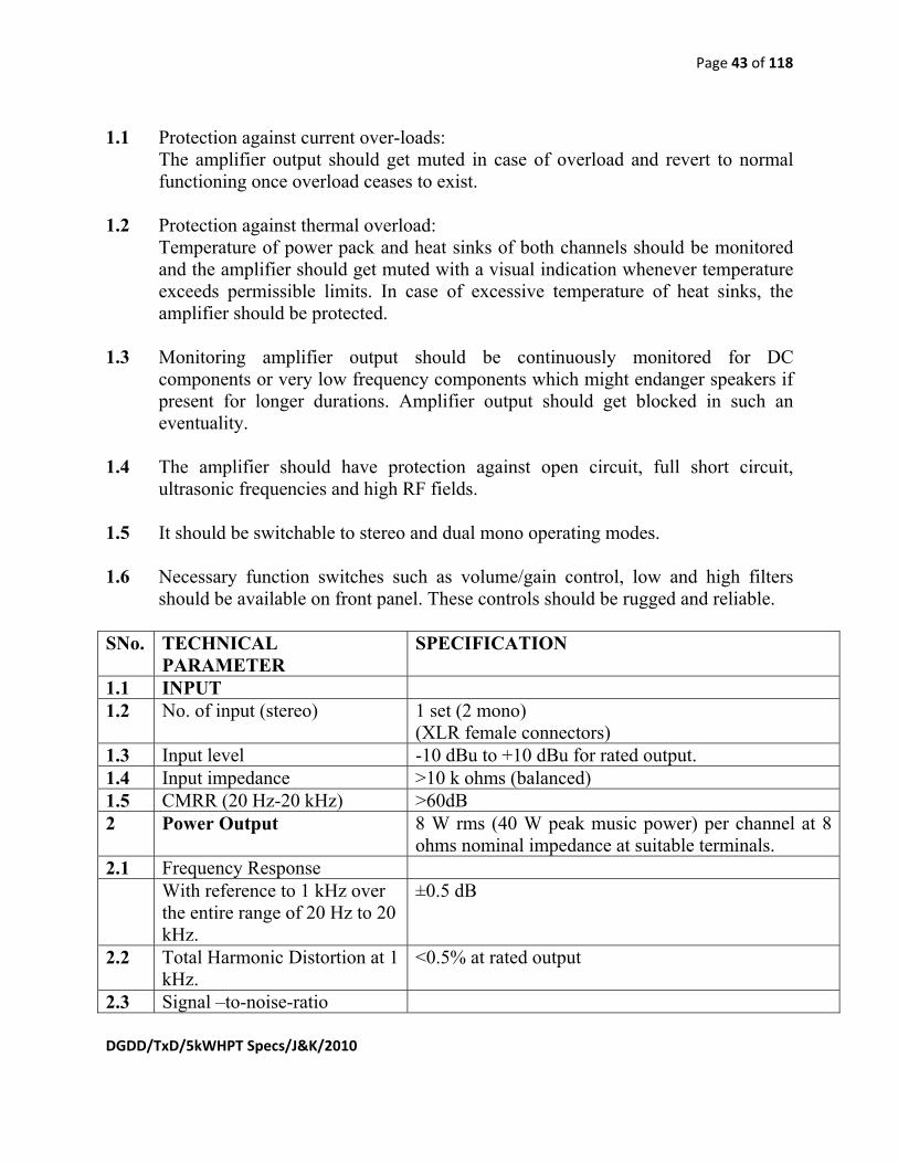
VI. SPECIFICATIONS OF AUDIO STEREO MONITORING AMPLIFIER 8 W 1.0 TECHNICAL SPECIFICATIONS: The amplifier should essentially have the following features:
Page 43 of 118
DGDD/TxD/5kWHPT Specs/J&K/2010
1.1 Protection against current over-loads: The amplifier output should get muted in case of overload and revert to normal functioning once overload ceases to exist.
1.2 Protection against thermal overload:
Temperature of power pack and heat sinks of both channels should be monitored and the amplifier should get muted with a visual indication whenever temperature exceeds permissible limits. In case of excessive temperature of heat sinks, the amplifier should be protected.
1.3 Monitoring amplifier output should be continuously monitored for DC components or very low frequency components which might endanger speakers if present for longer durations. Amplifier output should get blocked in such an eventuality.
1.4 The amplifier should have protection against open circuit, full short circuit,
ultrasonic frequencies and high RF fields. 1.5 It should be switchable to stereo and dual mono operating modes. 1.6 Necessary function switches such as volume/gain control, low and high filters
should be available on front panel. These controls should be rugged and reliable. SNo. TECHNICAL
PARAMETER SPECIFICATION
1.1 INPUT 1.2 No. of input (stereo) 1 set (2 mono)
(XLR female connectors) 1.3 Input level -10 dBu to +10 dBu for rated output. 1.4 Input impedance >10 k ohms (balanced) 1.5 CMRR (20 Hz-20 kHz) >60dB 2 Power Output 8 W rms (40 W peak music power) per channel at 8
ohms nominal impedance at suitable terminals. 2.1 Frequency Response With reference to 1 kHz over
the entire range of 20 Hz to 20 kHz.
±0.5 dB
2.2 Total Harmonic Distortion at 1 kHz.
<0.5% at rated output
2.3 Signal –to-noise-ratio

Page 44 of 118
DGDD/TxD/5kWHPT Specs/J&K/2010
With input shorted and at rated output (unweighted rms) at .dBu input (22 Hz-22 kHz)
Equal better than 85 dB
2.4 Damping factor >75 into 8 ohms at < 1 kHz 2.5 Power supply The amplifier shall work on 230v ± 10%, 48-52 Hz
single phase AC supply. 2.6 Level difference between the
channels Equal to or less than 0.5 dB
2.7 Phase difference between the channels
< 10°, 20 Hz to 20 kHz
2.8 Inter-channel X-Talk at 15 kHz
>75 dB at nominal level
2.9 Accessories All necessary accessories like
power cord and mating connectors shall be supplied along with the units. The standard accessories should be clearly mentioned in the quotation. Also, optional accessories if considered useful / recommended by the supplier should be quoted separately.
3. MECHANICAL: The amplifier should be 19” rack mounting type for mounting in a rack.
VII. SPECIFICATIONS OF AUDIO DISTRIBUTION AMPLIFIER WITH SUITABLE FRAME AND REDUNDANT POWER SUPPLY AND EXTENDER CARD
1. The system should be high-performance high reliability, analog audio distribution amplifier. 2. It should be of professional quality. 3. It should have flat frequency response a controlled roll-off and very low distortion. 4. The Isolation between the modules must be better than 90dB for audio frequency band. 5. The amplifier should be configured to 8 outputs designated to one input. 6. It should have balanced input and output.

Page 45 of 118
DGDD/TxD/5kWHPT Specs/J&K/2010
7. Technical Parameters- S. No. Description Parameters 1. Power supply 230VAC±10%, 50Hz. 2. Operating Temperature 0ºC to 45ºC 3. Input level 28dBu (Maximum) 4. output Impedance 66Ω 5. Output level 25dBu (Minimum) 6. CMRR >85dB 7. Cross talk >85dB isolation 8. Output Isolation >70dB 9. Frequency Response ±0.05dB (20Hz to 20KHz) 10. Gain Range -90 to 30dB in 0.5dB steps 11. S/N ratio >90dB
VIII. SPECIFICATIONS FOR AUDIO PROCESSOR 1. Introduction. 1.1 It should be a high quality stereo/dual mono audio processor for Analog television
audio, but should have digital signal processing only. 1.2 The transmitters should be rugged, reliable and stable in operation under Indian tropical condition. The climate may vary from very cold to hot, humid & dusty. 1.3 It should provide at it’s output sound with good loudness control as well as preserve the frequency balance of original sound while controlling subjective loudness. 1.4 It has to process audio available in the transmitter from a professional IRD (Satellite receiver) or a T.V. studio. 1.5 LCD/LED type meters on front panel for adjustment of parameters as well as for displaying required parameters for monitoring. 1.6 It should be a stand alone unit with built in tone generator for standard audio test tones upto 15kHz. 1.7 As the audio processor will be installed in very high R.F. field environment of 10kW UHF T.V. Transmitters, it should have proper R.F. Shielding. 1.8 The bypass test facility of the unit must be available. 1.9 The detailed technical specifications are provided below:

Page 46 of 118
DGDD/TxD/5kWHPT Specs/J&K/2010
Technical Specifications of Audio Processor Audio Processor must have the following specifications: 2. Analog Audio Input 2.1 Configuration: Stereo / Dual-Mono. 2.2 Impedance: > 10k Ω load impedance, electronically balanced. 2.3 Nominal Input Level: Software adjustable from –4.0 to +13.0 dBu (VU). 2.4 Maximum Input Level: +27 dBu. 2.5 Connectors: Two XLR-type, female, EMI-suppressed. Pin 1 chassis ground, Pins 2 (+) and 3 electronically balanced symmetrical. 2.6 Processing: Digital Signal Processing (DSP). 2.7 Filtering: RFI filtered. 3 Analog Audio Output 3.1 Configuration: Stereo, Flat or pre-emphasized at 50 μs. 3.2 Load Impedance: 600 Ω, balanced or unbalanced. 3.3 Output Level (100% peak modulation): Adjustable from –6 dBu to +24 dBu peak, into 600 ohm, software adjustable. 3.4 Signal to Noise Ratio: ≥ 90 dB unweighted (Bypass mode de-emphasised, 20 Hz-15 kHz bandwidth, referenced to 100% modulation). 3.5 L/R Crosstalk: ≤ -70 dB, 20 Hz-15 kHz. 3.6 Distortion: ≤ 0.01% THD (Bypass mode, de-emphasised) 20 Hz-15 kHz bandwidth. 3.7 Connectors: Two XLR –type, male, EMI-suppressed. Pin 1 chassis ground, Pins 2 (+) and 3 electronically balanced, floating and symmetrical. 3.8 Filtering: RFI filtered.

Page 47 of 118
DGDD/TxD/5kWHPT Specs/J&K/2010
4. General Parameters 4.1 Input Voltage: Single phase, 220Volt (rms) ± 15%, 50Hz. 4.2 Input Power Connector: IEC, EMI-suppressed. Detachable 3-wire power cord supplied. 4.3 Grounding: Circuit ground should be independent of chassis ground, and can be isolated or connected. 4.4 Safety Standards: As per latest international standards. 4.5 Operating Temperature: 0ºC to 45ºC for all operating voltage ranges. 4.6 Humidity: 0 to 95% RH, non-condensing. 4.7 Mounting: 19" Rack mounting, height must be specified by bidder in RU. 4.8 RFI / EMI: According to latest International standards. 4.9 Weight: Must be specified by bidder in Kg. IX. AUDIO PATCH CORDS (2ft)
10 nos. of stereo patch cords are to be provided for patching purposes. Their length is to be 2 ft. and should be of high quality, durable audio cable and jacks and match with AF jack panel.
X. VIDEO PATCH CORDS (2 ft)
10 nos. of video patch cords are to be provided for patching purposes. Their length is to be 2 ft. and should be of high quality, durable video cable and jacks and match with video jack panel.
Page 48 of 118
DGDD/TxD/5kWHPT Specs/J&K/2010
Annexure I-5
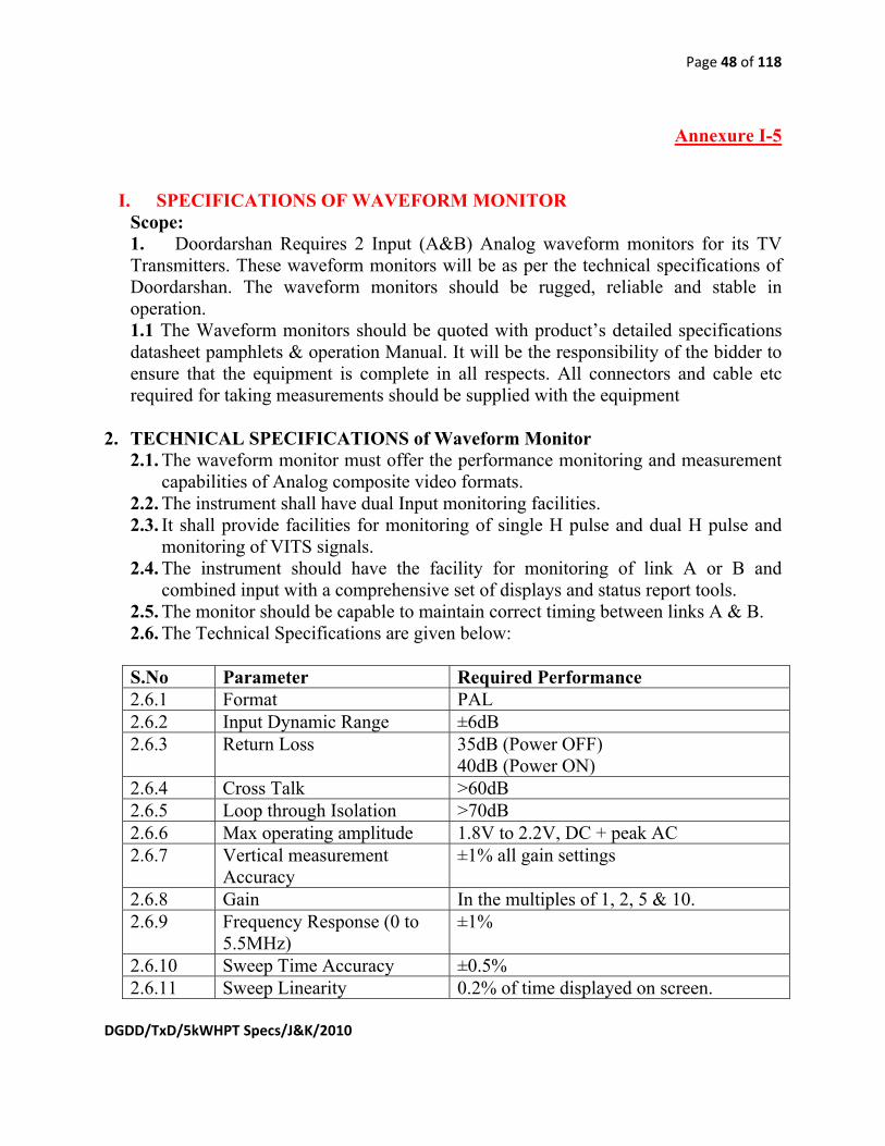
I. SPECIFICATIONS OF WAVEFORM MONITOR
Scope: 1. Doordarshan Requires 2 Input (A&B) Analog waveform monitors for its TV Transmitters. These waveform monitors will be as per the technical specifications of Doordarshan. The waveform monitors should be rugged, reliable and stable in operation. 1.1 The Waveform monitors should be quoted with product’s detailed specifications datasheet pamphlets & operation Manual. It will be the responsibility of the bidder to ensure that the equipment is complete in all respects. All connectors and cable etc required for taking measurements should be supplied with the equipment
2. TECHNICAL SPECIFICATIONS of Waveform Monitor 2.1. The waveform monitor must offer the performance monitoring and measurement
capabilities of Analog composite video formats. 2.2. The instrument shall have dual Input monitoring facilities. 2.3. It shall provide facilities for monitoring of single H pulse and dual H pulse and
monitoring of VITS signals. 2.4. The instrument should have the facility for monitoring of link A or B and
combined input with a comprehensive set of displays and status report tools. 2.5. The monitor should be capable to maintain correct timing between links A & B. 2.6. The Technical Specifications are given below:
S.No Parameter Required Performance 2.6.1 Format PAL 2.6.2 Input Dynamic Range ±6dB 2.6.3 Return Loss 35dB (Power OFF)
40dB (Power ON) 2.6.4 Cross Talk >60dB 2.6.5 Loop through Isolation >70dB 2.6.6 Max operating amplitude 1.8V to 2.2V, DC + peak AC 2.6.7 Vertical measurement
Accuracy ±1% all gain settings
2.6.8 Gain In the multiples of 1, 2, 5 & 10. 2.6.9 Frequency Response (0 to
5.5MHz) ±1%
2.6.10 Sweep Time Accuracy ±0.5% 2.6.11 Sweep Linearity 0.2% of time displayed on screen.

Page 49 of 118
DGDD/TxD/5kWHPT Specs/J&K/2010
3 General Requirement: 3.1 Test Certificate of the instrument shall accompany each instrument on
delivery 3.2 The Equipment should have minimum 1 no. USB 2.0 Port.
USB port should support USB flash drives/ connection to PC. 3.3 The Software for PC Communications should be provided to work
between a Windows PC and the waveform monitor via USB. It should be able to Transfer and save settings, waveforms, measurements and screen images. Matching cables must be supplied with each equipment.
3.4 The Waveform monitor must have BNC (female) input connectors. It should also have the facility loop through of video signal to monitor it on the video monitors.
3.5 Power Supply The Oscilloscope shall work on 220V+10%, 50-60 Hz AC supply. The power supply unit of the equipment shall be protected against overload short circuit and over-voltage etc.
3.6 Environmental The equipment shall be capable of performing satisfactorily in the temperature range from 0 deg Cel to 45 deg Cel and humid conditions of 85% at 40 deg C.
4.0 ACCESSORIES
All the essential accessories also to be included in the offer.
II. SPECIFICATIONS OF VU METER Specification for VU meter
1. It should be a stand alone unit, simple to operate and 19” rack mount. 2. It must be a professional level monitoring in broadcast systems. 3. The unit should have at least two Analog input (XLR type) and also have facility
to measure digital input signals (AES/EBU). 4. The input range must be at least ±10dB. 5. Unit should have the facility of internal speakers.
6. Technical Specifications: Srl. No. Description Parametric value 6.1
Input Impedance 600 ohm.

Page 50 of 118
DGDD/TxD/5kWHPT Specs/J&K/2010
6.2
Maximum Input level 20dBU.
6.3
Frequency of operation 20Hz to 20KHz.
6.4
Accuracy ±1dB.
6.5
Distortion <0.1%.
6.6 S/N Ratio ≥80dB.

Page 51 of 118
DGDD/TxD/5kWHPT Specs/J&K/2010
Annexure I-6 SPECIFICATIONS OF INSTALLATION MATERIALS: 1. All the installation material like Cables and Connectors must be of high quality, used for broadcasting system for a good transmission performance. 2. The VSWR of all RF feeder components must be less than 1.05. 3. There should have a firm grip between various coaxial feeder components at the time of installation. 4. The power cables should be capable to handle the power supplied to it. 5. The impedance of the RF Cables should be as per their specified nomenclature. 6. All the installation material must be of reputed make.

Page 52 of 118
DGDD/TxD/5kWHPT Specs/J&K/2010
Annexure I-7 SPECIFICATIONS OF COMPUTER WITH 1 KVA UPS AND LASERJET PRINTER: 1.0 Scope: Doordarshan (DD) intends to procure Computer system based on latest technology. The computers should be rugged, reliable, and stable in operation under very cold to hot, humid and dusty environmental conditions. Detailed specifications of the Computers are given in this document. The Computers will be supplied along with Uninterrupted Power Supply (UPS) and Laser printer. The computer manufacturer / bidder must have his local office / representative in India. 1. 1 Computer Configuration S.No. Description Specification
a. CPU Intel Core 2 Duo 2.93 Ghz or better, 3MB L2 cache and 800 MHz FSB
b. Chipset Intel 3 series/nVidia GForce 7 series or better on OEM Motherboard
c. Bus Architecture Integrated Graphics, 2 PCI, 1 PCI Express x 1 and 1 PCI Express x 16
d. Memory 2 GB 667 MHz DDR2 RAM with 4GB Expandability
e. Hard Disk Drive 500 GB 7200 rpm Serial ATA HDD f. Monitor 48.2 cm (19 inch) TFT Digital Colour Monitor
TCO-03 certified g. Keyboard 104 keys h. Mouse Optical i. Bays 4 Nos. (2 Nos. 5.25 inches for Optical Media
Drives and 2 Nos. 3.5 inches for Hard Disk Drives)
j. Ports 6 USB Ports (with at least 2 in front), 1 Serial audio ports for microphone and headphone in front
k. Cabinet Mini tower l. DVD ROM Drive 16X or better DVD ROM Drive m. Networking
facility 10/100/1000 on board integrated Network Port with remote booting facility remote system installation, remote wake up
n. Operating System Windows Seven professional preloaded with Media and Documentation and Certificate of Authenticity
o. OS Certifications Win Logo Seven professional OS and Linux Certification

Page 53 of 118
DGDD/TxD/5kWHPT Specs/J&K/2010
p. Power Management
Screen Blanking, Hard Disk and System Idle Mode in Power On, Set up Password, Power supply SMPS Surge protected
q. Preloaded Software
Norton, McAfee, or equivalent Antivirus (Latest Version) with 360 days License and open office
2. Laser Printer S.No. Description Specification a Output Type Black and White b Resolution 600 x 600 dpi c Page per Minute(PPM) 16 d Paper size A4 e Interface USB 2.0 f Necessary cables & Utility Software 3.0 1000 VA UPS S.No
Description Specification
a Capacity 1000 VA b Output waveform Stepped approximation to a Sinewave c Voltage on Mains 100 - 265VAC d Frequency(Input) 47 - 53Hz e Backup time 20 minutes f Frequency(on Battery) 50Hz + / - 1% g Transfer Time <20 milli seconds h Over Load Indication 100% for 60 seconds, Indications Via LED & Audible
alarm with 3 times restart i Charger Constant Power, 2 step charging Input voltage range 100
- 270V j Short circuit protection Multiple short circuit protection provided k Protection Overload, short circuit, low battery Over charge, Main
slow & High input voltage l Battery Sealed Maintenance free Cold Start, No-load Auto-
Shutdown
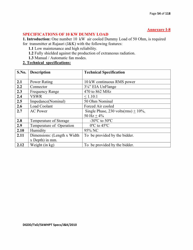
Page 54 of 118
DGDD/TxD/5kWHPT Specs/J&K/2010
Annexure I-8 SPECIFICATIONS OF 10 KW DUMMY LOAD 1. Introduction: One number 10 kW air cooled Dummy Load of 50 Ohm, is required for transmitter at Rajauri (J&K) with the following features:
1.1 Low maintenance and high reliability. 1.2 Fully shielded against the production of extraneous radiation. 1.3 Manual / Automatic fan modes.
2. Technical specifications:
S.No. Description
Technical Specification
2.1 Power Rating 10 kW continuous RMS power 2.2 Connector 3⅛” EIA UnFlange 2.3 Frequency Range 470 to 862 MHz 2.4 VSWR < 1.10:1 2.5 Impedance(Nominal) 50 Ohm Nominal 2.6 Load Coolant Forced Air cooled 2.7 AC Power Single Phase, 230 volts(rms) + 10%,
50 Hz + 4% 2.8 Temperature of Storage -30ºC to 50ºC 2.9 Temperature of Operation 0ºC to 45ºC 2.10 Humidity 95% NC 2.11 Dimensions: (Length x Width
x Depth) in mm. To be provided by the bidder.
2.12 Weight (in kg) To be provided by the bidder.

Page 55 of 118
DGDD/TxD/5kWHPT Specs/J&K/2010
Annexure I-9 SPECIFICATIONS OF MEASURING EQUIPMENT:
I. SPECIFICATIONS OF COLOUR TEST PATTERN & TONE GENERATOR
1. Doordarshan requires broadcast quality colour test pattern and tone generator with test signals for analog TV transmitters. 2. It should work for PAL/625 line system. 3. The unit should have SNMP remote control facility to integrate automated service. 4. Technical parameters-
Srl. No. Description Parametric values 4.1 Power supply 230VAC±10%, 50Hz 4.2 Output Connector – video/audio BNC/XLR 4.3 Operating Temperature 0ºC to 45ºC 4.4 Output Impedance - video/audio 75Ω/12 Ω 4.5 Video Output Return loss >30dB 4.6 Video Test signals 75% & 100% colour bar,
linearity, flat field, Multiburst, sweep, pulse & bar etc.
4.7 Audio Level -48dBU to +12dBU (Resolution 1dB)
II. SPECIFICATIONS OF T.V. ANALYSER/DEMODULATOR
TV Demodulators are required for measurements and monitoring the quality of transmission of the TV Transmitter. The detailed technical specifications are given blow:
1 GENERAL
1.1 It should be capable of operation in TV band IV, V(470 MHz to 860MHz). ( CCIR PAL G )
1.2
Channel change should be possible by DIP switch / Hex switch or Electronically by push buttons.
1.3 It should have capability for RF and IF measurements. 1.4 It should have zero reference pulse facility to measure visual modulation
depth. 1.5 It should have switch selected sound trap ‘ON’ & ‘OFF’ facility. 1.6 It should have switch selected envelope detection & synchronous detection. 1.7 It should have squelch for noise suppression in case of absence of sound
carrier failure.
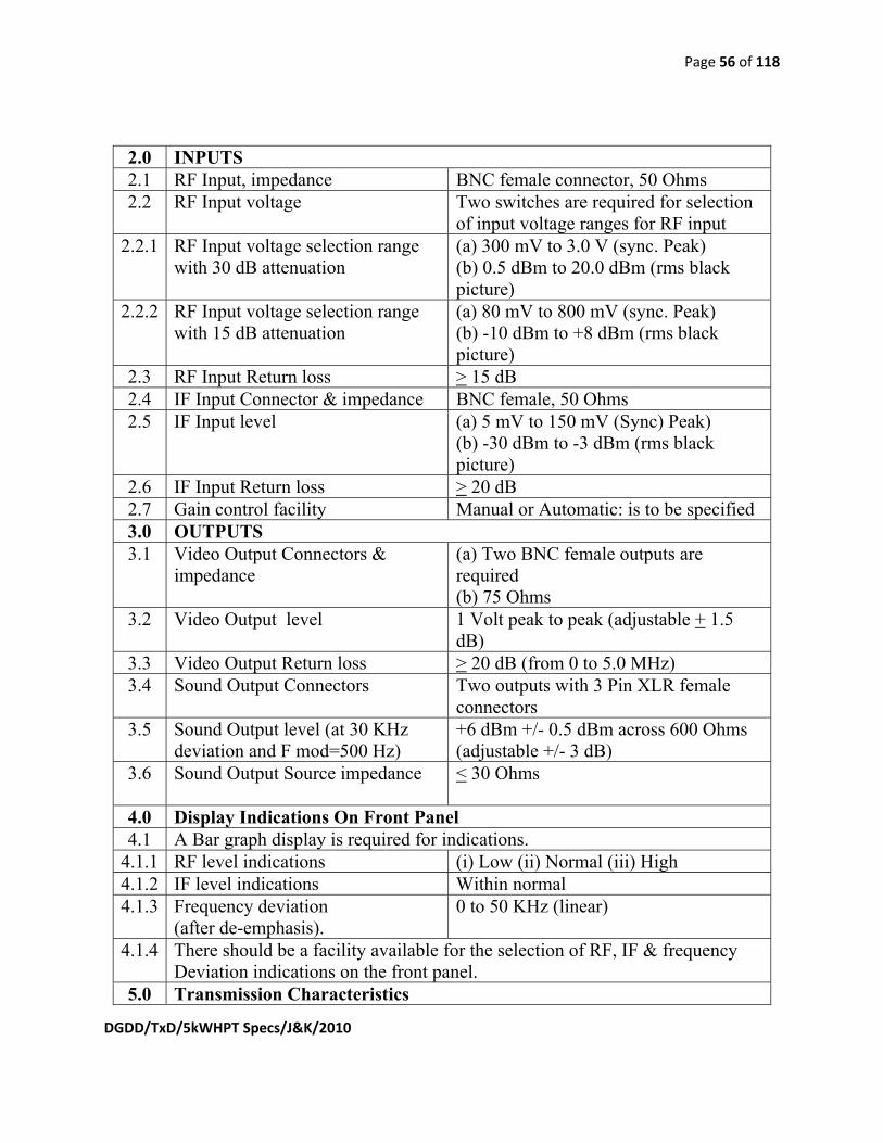
Page 56 of 118
DGDD/TxD/5kWHPT Specs/J&K/2010
2.0 INPUTS 2.1 RF Input, impedance BNC female connector, 50 Ohms 2.2 RF Input voltage Two switches are required for selection
of input voltage ranges for RF input 2.2.1 RF Input voltage selection range
with 30 dB attenuation (a) 300 mV to 3.0 V (sync. Peak) (b) 0.5 dBm to 20.0 dBm (rms black picture)
2.2.2 RF Input voltage selection range with 15 dB attenuation
(a) 80 mV to 800 mV (sync. Peak) (b) -10 dBm to +8 dBm (rms black picture)
2.3 RF Input Return loss > 15 dB 2.4 IF Input Connector & impedance BNC female, 50 Ohms 2.5 IF Input level (a) 5 mV to 150 mV (Sync) Peak)
(b) -30 dBm to -3 dBm (rms black picture)
2.6 IF Input Return loss > 20 dB 2.7 Gain control facility Manual or Automatic: is to be specified 3.0 OUTPUTS 3.1 Video Output Connectors &
impedance (a) Two BNC female outputs are required (b) 75 Ohms
3.2 Video Output level 1 Volt peak to peak (adjustable + 1.5 dB)
3.3 Video Output Return loss > 20 dB (from 0 to 5.0 MHz) 3.4 Sound Output Connectors Two outputs with 3 Pin XLR female
connectors 3.5 Sound Output level (at 30 KHz
deviation and F mod=500 Hz) +6 dBm +/- 0.5 dBm across 600 Ohms (adjustable +/- 3 dB)
3.6 Sound Output Source impedance < 30 Ohms
4.0 Display Indications On Front Panel 4.1 A Bar graph display is required for indications.
4.1.1 RF level indications (i) Low (ii) Normal (iii) High 4.1.2 IF level indications Within normal 4.1.3 Frequency deviation
(after de-emphasis). 0 to 50 KHz (linear)
4.1.4 There should be a facility available for the selection of RF, IF & frequency Deviation indications on the front panel.
5.0 Transmission Characteristics

Page 57 of 118
DGDD/TxD/5kWHPT Specs/J&K/2010
5.1 Specifications for Video Channel 5.1.1 Amplitude Vs frequency response (a) +/- 0.5 dB from 100 KHz to 4.43
MHz (with sound trap) (b) +/- 0.5 dB from 100 KHz to 5.0 MHz (without sound trap)
5.1.2 Group delay vs frequency characteristics
a) +/- 30 ns upto 4.43 MHz (with sound trap) b) +/- 15 ns upto 5.0 MHz (without sound trap)
5.1.3 Differential gain < 3% 5.1.4 Differential phase < ±2 deg. 5.1.5 Tilt at 50 Hz < 2% 5.1.6 Luminance bar amplitude error < 2% 5.1.7 Base line distortion < 2% 5.1.8 2T amplitude error < 5% 5.1.9 Signal to noise ratio
(At an input level of 10 dBm) > 55dB
6.0 Sound Channel 6.1 Inter carrier frequency 5.5 MHz 6.2 Frequency response +/- 1.0 dB wrt 50 μs de-emphasis from 50
to 15 KHz 6.3 Harmonic distortion
(At 50 KHz deviation and F mod=500 Hz)
< 1%
6.4 Inter-carrier S/N ratio (At 50KHz deviation)
> 55 dB
7.0 Power Supply 230 V +/- 10%,50 Hz, single phase 7.1 Dimensions/Weight To be mentioned by the supplier 7.2 Mounting 19” Rack mountable 7.3 Temperature for operation 0 degree to 45 degree centigrade 7.4 Relative humidity 90% 7.5 Max Altitude 3500 Meter.
The TV demodulator must be supplied with Mounting Arrangement Hardware (19” Rack Mount Kit) and all other standard Cables and other accessories.

Page 58 of 118
DGDD/TxD/5kWHPT Specs/J&K/2010
III. Specification of Digital storage, 2 Channel 100 MHz Oscilloscope Scope: 1.0 Doordarshan Requires 100 MHz 2 Channel Oscilloscopes for its TV Transmitters. These oscilloscopes will be as per the technical specifications of Doordarshan. The oscilloscope should be rugged, reliable and stable in operation. 1.1 The oscilloscopes should be quoted with product’s detailed specifications datasheet pamphlets & operation Manual. It will be the responsibility of the bidder to ensure that the equipment is complete in all respects. All connectors and cable etc required for taking measurements should be supplied with the equipment 2.0 TECHNICAL SPECIFICATIONS of 100 MHz OSCILLOSCOPE The instrument shall have dual channel measurement facilities. It shall provide facilities for measurement of rise time, fall time, positive width, negative width, frequency, period, mean, cycle RMS, minimum, maximum, peak to peak etc. It shall provide facilities for automatic measurements of peak to peak voltage, frequency, period, rise time and fall time functions. S.No Parameter Required Performance 2.1 Bandwidth DC to 100 MHz (at- 3dB) 2.2 Vertical Operating Modes CH1, CH2, Add, Subtract and FFT 2.3 Deflection Accuracy 3% or better 2.4 Sensitivity 5mV/Div to 5V/Div in steps 2.5 Rise Time less than or equal to 3.5n sec 2.6 Channel to Channel CMR At least 100:1 at 60Hz 2.7 Maximum Input 300V rms Cat. II; 2.8 Input Coupling AC, DC and Ground 2.9 Input Impedance
1 MΩ ± 2% in parallel with 20 pF ±3 pF
2.10 HORIZONTAL SYSTEM 1 Sweep display modes Y-T and X-Y mode 2 Sweep Mode Auto, Normal and Single Sequence 3 Time base Accuracy 50 PPM
4 Range 5 ns/div to 50 sec/div 5 X-Y Mode 5(a) X-axis BW DC to 100 MHz 5(b) Y-axis BW Same as for the vertical system

Page 59 of 118
DGDD/TxD/5kWHPT Specs/J&K/2010
2.11 TRIGGERING SYSTEM 1 Source CH1, CH2, AC line & external 2 Trigger Operating modes Auto Normal & Single Sequence 3 Time Base Range 5ns/div to 50 sec/div 4 Trigger Coupling AC, DC , HF reject & LF reject, Noise
Reject 2.12 Triggering Types 5(a) Edge Conventional level driven trigger.
Positive or negative slope on any channel coupling selection
5(b) Video Trigger on all lines or individual line, odd/ even or all fields from composite video, or broadcast standards (NTSC, PAL, SECAM)
5 (c ) Pulse Width Trigger on a pulse width less than, greater than, equal to, or not equal to a selectable time limit ranging from 33 ns to 10 sec
2.13 DIGITAL STORE SYSTEM 1 Real time Sample Rate
maximum 500 Mega samples per second per channel (simultaneously in both channels)
2 Acquisition Modes Average, Sample and Peak detect ( Minimum 75 MHz analog BW)
3 Resolution Vertical 8 bit 4 Record Length/memory Upto 2500 points or more per channel in
dual channel mode 5 Memory 2 Waveforms
10 front panel setups 6 Display refresh rate (Update
rate) 180 waveform/sec
2.14 CURSORS READOUT 1 Cursor measurement [Δ]T, 1[Δ]T (frequency), [Δ]V.
2.15 ACCESSORIES 1 Power cord/ probes etc. Power Cord = 1no.
Probe (10:1) = 2 Nos. (1 no. per Channel). And any other connectors required for normal functioning of the Oscilloscope.
2.16 DISPLAY 1 Display LCD
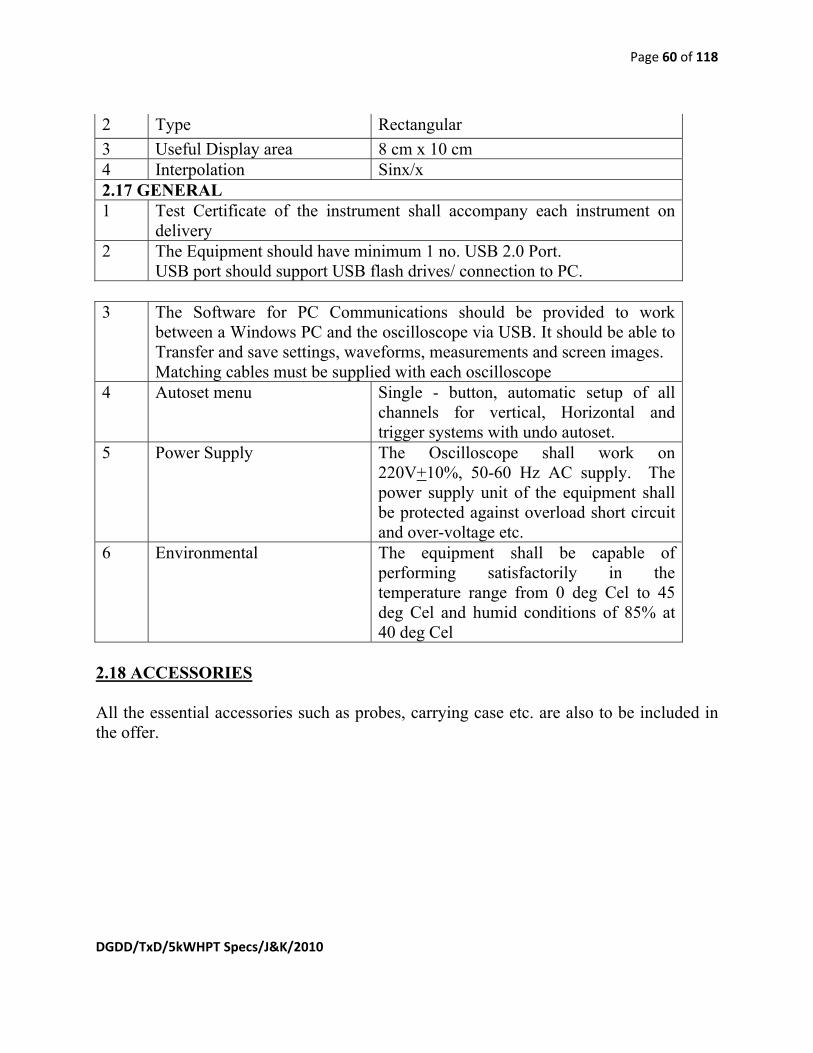
Page 60 of 118
DGDD/TxD/5kWHPT Specs/J&K/2010
2 Type Rectangular 3 Useful Display area 8 cm x 10 cm 4 Interpolation Sinx/x 2.17 GENERAL 1 Test Certificate of the instrument shall accompany each instrument on
delivery 2 The Equipment should have minimum 1 no. USB 2.0 Port.
USB port should support USB flash drives/ connection to PC. 3 The Software for PC Communications should be provided to work
between a Windows PC and the oscilloscope via USB. It should be able to Transfer and save settings, waveforms, measurements and screen images. Matching cables must be supplied with each oscilloscope
4 Autoset menu Single - button, automatic setup of all channels for vertical, Horizontal and trigger systems with undo autoset.
5 Power Supply The Oscilloscope shall work on 220V+10%, 50-60 Hz AC supply. The power supply unit of the equipment shall be protected against overload short circuit and over-voltage etc.
6 Environmental The equipment shall be capable of performing satisfactorily in the temperature range from 0 deg Cel to 45 deg Cel and humid conditions of 85% at 40 deg Cel
2.18 ACCESSORIES All the essential accessories such as probes, carrying case etc. are also to be included in the offer.
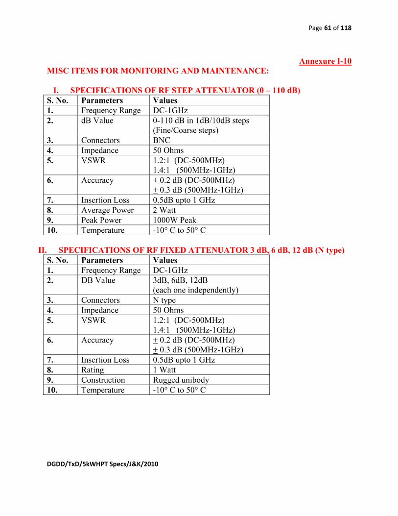
Page 61 of 118
DGDD/TxD/5kWHPT Specs/J&K/2010
Annexure I-10 MISC ITEMS FOR MONITORING AND MAINTENANCE:
I. SPECIFICATIONS OF RF STEP ATTENUATOR (0 – 110 dB)
S. No. Parameters Values 1. Frequency Range DC-1GHz 2. dB Value 0-110 dB in 1dB/10dB steps
(Fine/Coarse steps) 3. Connectors BNC 4. Impedance 50 Ohms 5. VSWR 1.2:1 (DC-500MHz)
1.4:1 (500MHz-1GHz) 6. Accuracy + 0.2 dB (DC-500MHz)
+ 0.3 dB (500MHz-1GHz) 7. Insertion Loss 0.5dB upto 1 GHz 8. Average Power 2 Watt 9. Peak Power 1000W Peak 10. Temperature -10° C to 50° C
II. SPECIFICATIONS OF RF FIXED ATTENUATOR 3 dB, 6 dB, 12 dB (N type)
S. No. Parameters Values 1. Frequency Range DC-1GHz 2. DB Value 3dB, 6dB, 12dB
(each one independently) 3. Connectors N type 4. Impedance 50 Ohms 5. VSWR 1.2:1 (DC-500MHz)
1.4:1 (500MHz-1GHz) 6. Accuracy + 0.2 dB (DC-500MHz)
+ 0.3 dB (500MHz-1GHz) 7. Insertion Loss 0.5dB upto 1 GHz 8. Rating 1 Watt 9. Construction Rugged unibody 10. Temperature -10° C to 50° C

Page 62 of 118
DGDD/TxD/5kWHPT Specs/J&K/2010
Annexure I-11 ANTENNA SYSTEM:
I. SPECIFICATIONS OF 10 KW, BAND IV/V UHF SUPERTURNSTILE, OMNI-DIRECTIONAL, BROADBAND ANTENNA SYSTEM
a) Scope: 1. Doordarshan requires antenna system, self supporting, enclosed in Structural Fiber
Glass Radome to be mounted on top of AIR steel tower AT Rajouri. 2. The antenna will be used for radiating 10KW power in UHF band. The combined
output of two Nos. 5 kW each Transmitter shall be fed to this antenna. 3. The Channel Details of Transmitters are given below. 4. Less weight, Low wind load and de-icing effect of antenna is basic requirement. 5. The Antenna System should be complete in all respect.
b) Details of Channel frequency for operation of the antenna system (Please
refer Para 1.7 of DD specifications):
S.No Programme Channel
Frequency band Operating Channel Frequency
1.
DD National UHF band IV/V (470MHz to 862 MHz)
Ch# 32(.) PAL- G
2. DD News UHF band IV/V (470MHz to 862 MHz)
Ch# 34(.) PAL- G
c) Technical Specifications:
S. No.
Parameter Specification
1. Type / Configuration Superturnstile, self supporting, top mounted on Square Steel Tower.
2. Frequency Range Broadband in UHF Band (470 MHz to 862 MHz). Capable of operation on any channel in the UHF band.
3. Power Handling Capacity 10 kW 4. Polarization Horizontal 5. Horizontal Radiation
Pattern Omni directional.
6. Permissible limit of: Variation in the HRP Value
Maximum + 1.2dB for Omnidirectional.
7. Vertical Radiation A typical pattern should be attached, It should be possible to introduce Beam tilt

Page 63 of 118
DGDD/TxD/5kWHPT Specs/J&K/2010
and Null fill. Typical value of Beam till is 0.5° and Null fill is 10%.
8. Net gain of the 'antenna System' in dBd (with respect to half wave dipole) after deducting all losses in branch feeder cables, splitters/dividers etc. (Formula for Net Gain = Horizontal Directivity + Vertical Directivity - losses)
Not less than (minimum) 11 dBd for Omni directional antenna system, at midband frequency 666 MHz (with 0.5 deg. beam tilt and 10% null fill). The complete information about Net Gain Calculation as per the formula provided is mandatory.
9. horizontal directivity (dBd)
Numerical value in dBd must be provided.
10. vertical directivity (dBd) Numerical value in dBd must be provided. 11. (a) branch feeder losses
(dB) (b) splitter losses (dB) (c) beam tilt losses (dB) (d) null fill losses (dB)
Numerical values for all losses in dB must be provided.
12. Input impedance 50 ohms 13. VSWR of the whole
Antenna System a) 1.10:1 Broadband (Max) (In the whole UHF band IV & V frequency range i.e. 470MHz to 862MHz) b) 1.05:1 at Vision carriers. ( Programme channel wise frequency detail is given in II above)
14. Input Connector (Single Input)
3⅛” EIA flange
Mechanical Characteristics of Antenna System 15. Maximum wind speed for
survival 216 km/hr (60m/sec)
16. Provision of Radome To be provided, details must be given. 17. Climbing Access A safe climbing access for antenna for
repairing of antenna system i.e. branch feeder cables, panels, power splitters and access to AOL etc. must be available.
18. Antenna support structure Antenna is to be supplied along with

Page 64 of 118
DGDD/TxD/5kWHPT Specs/J&K/2010
for mounting and hauling up.
antenna support structure for mounting and hauling up, which is to be fixed on top of square steel AIR towers. Necessary mounting assembly should also be provided.
19. Lightening Protection & Aviation Light
(a) A lightening conductor and twin Aviation Lights (LED Type) with inter-blinking arrangement at the tower top should be provided with Antenna support structure. The aviation lights on tower must use 24 Volt D.C. power supply. A suitable length for power supply cable should also be supplied with lights. (b) Colour of the radome of antenna system must be as per ICAO norms.
20. Antenna System Weight (Dead Load)
Total dead weight of antenna system with radome, support structure etc may be provided in kg. It should not be more than 500kg.
21. Wind Load The wind load of the whole antenna system with radome support structure etc at wind speed of 216 km/hr should be provided in Kg. It should not be more than 750Kg.
22. Total Antenna System height
The total height of the complete Antenna System should be provided with detailed drawing. It should not be more than 5.5meter.
23. Accessories required All accessories required for completeness of the system, should be quoted with the offer.
d) General Instructions:
1. All the relevant technical pamphlets, data sheets drawings, block diagrams list of all items quoted with description of the functioning of the system should be attached with the offer, otherwise offer may not be considered for evaluation.
2. The details of past supply for the similar Antenna system should be provided in the following format:

Page 65 of 118
DGDD/TxD/5kWHPT Specs/J&K/2010
Name and Postal Address of the Firm where the antenna is supplied
Name of the contact person with E mail id
Telephone and Fax Nos.
Make and Model of the Antenna System supplied
Power capacity of the similar antenna system supplied
Quantity supplied
3. The set of essential spares, modules, tool and other necessary equipment required,
should also be quoted separately with the offer as optional items. 4. A detailed installation, operation and maintenance manuals along with relevant
drawings, pamphlets, data sheet etc should be attached with the offer for analyzing the technical requirement of Doordarshan. The offer without operation and maintenance manual will not be considered for analysis and may be rejected with out making any reference to the firm.
5. The Antenna system manufacturer /bidder must have his local office / representative in India. The name, contacts, address of local office / representative along with manufacturer’s authority letter in favour of local representative must be given with the offer. The local office / representative in India will be nodal point for resolving after sales issues. In case any module/part of the antenna system requires repairs at factory, the same would be handed over to local office / representative in India, who would arrange repairs locally or export the defective modules/part to its O.E.M. and arrange its repair etc. The repaired item, will have to be delivered by the local representative at transmitter site in India.
6. SPARES:- Essential spares required for the maintenance of the antenna system should also be quoted separately. The value of such spares should not exceed 5% of the total cost of the equipment. Doordarshan shall exercise option to order spares separately. The spare cost shall not be accounted for deciding the offer of the main antenna system. The manufacture shall also give a certificate attached with the offer to supply maintenance support and all spare during the life time of the Antenna. The life of the Antenna system should be certified by the manufacturer. This is an essential requirement. The cost of spare shall not be taken into account for ascertaining the lowest bidder.
7. ACCESSORIES:- All essential accessories required that shall complete the system should be include in the offer.
8. PRICE:- The bidder along with the offer must quote item wise price of all the items, which constitute the system, separately. A copy of the “price bid” showing/provided all items of bill of material without showing the prices must be attached with the “Technical bid”.
9. TECHNICAL LITERATURE: i. Two sets of technical data sheets of the equipment offered, Installation manuals,
operational and service manual shall be supplied with the each set of antenna system.
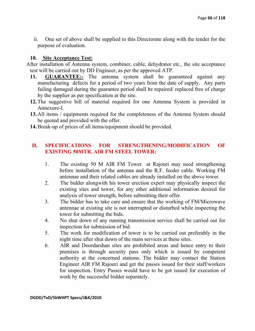
Page 66 of 118
DGDD/TxD/5kWHPT Specs/J&K/2010
ii. One set of above shall be supplied to this Directorate along with the tender for the purpose of evaluation.
10. Site Acceptance Test:
After installation of Antenna system, combiner, cable, dehydrator etc., the site acceptance test will be carried out by DD Engineer, as per the approved ATP. 11. GUARANTEE:- The antenna system shall be guaranteed against any
manufacturing defects for a period of two years from the date of supply. Any parts failing damaged during the guarantee period shall be repaired/ replaced free of charge by the supplier as per specification at the site.
12. The suggestive bill of material required for one Antenna System is provided in Annexure-I.
13. All items / equipments required for the completeness of the Antenna System should be quoted and provided with the offer.
14. Break-up of prices of all items/equipment should be provided. II. SPECIFICATIONS FOR STRENGTHENING/MODIFICATION OF
EXISTING 50MTR. AIR FM STEEL TOWER:
1. The existing 50 M AIR FM Tower at Rajouri may need strengthening before installation of the antenna and the R.F. feeder cable. Working FM antennae and their related cables are already installed on the above tower.
2. The bidder alongwith his tower erection expert may physically inspect the existing sites and tower, for any other additional information desired for analysis of tower strength, before submitting their offer.
3. The bidder has to take care and ensure that the working of FM/Microwave antennae at existing site is not interrupted or disturbed while inspecting the tower for submitting the bids.
4. No shut down of any running transmission service shall be carried out for inspection for submission of bid.
5. The work for modification of tower is to be carried out preferably in the night time after shut down of the main services at these sites.
6. AIR and Doordarshan sites are prohibited areas and hence entry to their premises is through security pass only which is issued by competent authority at the concerned stations. The bidder may contact the Station Engineer AIR FM Rajouri and get the passes issued for their staff/workers for inspection. Entry Passes would have to be got issued for execution of work by the successful bidder separately.

Page 67 of 118
DGDD/TxD/5kWHPT Specs/J&K/2010
7. The job related with strengthening of AIR FM Tower includes: (a) Preparing separate drawings after analyzing the exact requirement of
strengthening for bearing the loading of tower due to new antenna system and RF feeder cable.
(b) Designing, fabricating, supplying, modifying and erecting necessary members, interface, nuts, bolts, washers, etc. on the tower for its strengthening as per the analysis and structural requirement.
(c) Carrying out necessary modifications in the tower section, members and top interface required to install the UHF panel type dual feed antenna on the top of the tower.
(d) The drawings and analysis for modifications/strengthening of towers are to be got approved by Indian institute of Technology at Chennai/ Delhi/ Mumbai/ Kanpur/ Roorkee/Indian Institute of Science Bangalore/Structural Engineering Research Centre, Chennai. The copy of the approval has to be submitted to AIR Directorate before the work is taken up at site.
8. General Instructions regarding strengthening of air Tower are given
below: (a) Bidder shall be fully responsible for soundness of the modified design of
tower, fabrication of necessary sections and fasteners etc., SITC of (1+1) TV Transmitters, including installation of antenna, R.F. cable, combiner, dehydrator, electrical works, earthing etc. besides the transmitters, and safety of the complete turnkey project.
(b) The bidder shall complete and include all minor/major items of appurtenances and accessories which may not have been enumerated in this specification and BOM but which are useful and necessary for ensuring strengthening of tower and installation of antenna, R.F. cable, combiner, dehydrator in all respects and complete the turnkey project as per good engineering practices and no extra charges will be paid for providing and installing such minor/major items.
(c) Prior approval of the purchaser, in writing, shall be obtained from DG:AIR if the bidder desires to sublet or assign any section of the work associated with the fabrication, work related with strengthening of tower etc. Such permission of consent shall not, however discharge the bidder from his liabilities in this contract or any part thereof.
(d) The bidder shall make his own arrangements for power supply, water and the storage of materials and their safe custody at site for the entire turnkey project.
(e) Bidder shall make good all damage to the purchaser’s building, property, equipment etc. how-so-ever arising from the project and in the course of

Page 68 of 118
DGDD/TxD/5kWHPT Specs/J&K/2010
such work and throughout the period during which the safety of tower and other property of the purchaser is guaranteed.
(f) The bidder shall indemnify and hold harmless the purchaser against any claims in respect of damages to building, property situated nearby, not belonging to the purchaser, how-so-ever arising from the strengthening of the tower work and in course of such work and throughout the period during which the safety of tower is guaranteed.
(g) The bidder shall indemnify and hold harmless the purchaser against claims in respect to injury any mishap to any person how-so-ever arising out of the tower related work and throughout the period of turnkey project, during which the safety of the tower is guaranteed.
(h) The bidder shall discharge all obligations under the Indian workmen’s compensation act any local, state laws and regulations in so far as it affects the workmen in his employment.
(i) The bidder shall make his own arrangement for employing labour, skilled & unskilled, and shall make his own arrangement for providing accommodation for his workmen at site or elsewhere.
(j) The bidder shall hold the purchaser and his employees safe, harmless and immune from any liability that may arise out of infringements of patents and copyright associated with design, fabrication and modification in tower.
(k) The specifications indicated herein are only to guide the bidder about the requirements of the purchaser. Detailed analysis and design for strengthening of the tower from all aspects shall be got worked out by the bidder, keeping in view the effects of local meteorological conditions like wind velocity, seismic zone, temperature, latest codal provisions and as per good engineering practice to ensure the safety of the tower. Tender shall consult Wind & seismic zones as per latest BIS codes. The bidder may also consult structural engineer(s)/structural engineering institute regarding the modifications in tower for the new antenna system. Only Indian codes are acceptable for the work of strengthening of existing towers.
(l) Detailed information concerning design parameters such as loads due to wind effect as per IS:875-1987 and seismic effect as per IS:1893 – 2002 with latest amendments, dead loads, antenna loads, loads combination considered, design philosophy along with other information and shall contain the following:
i. Wind speed zone, terrain category, topographic factor etc. ii. Seismic zones factor, importance factor, response reduction
factor etc. iii. Antennae loads due to proposed TV antenna, FM, MW dishes or
any other communication or broadcast antennae installed on tower.

Page 69 of 118
DGDD/TxD/5kWHPT Specs/J&K/2010
iv. Load combination considered. Design criteria, analytical model & philosophy.
v. Deflection at top of tower including UHF antenna system and reaction at base in most critical load combination.
vi. Detailed information about material used in sections & accessories such as quality of steel, fasteners with reference to relevant BIS codes.
vii. Details of aviation light, type model, battery back up, sun switch, earthing, lightening arrestor arrangement power cable details etc, with drawings, catalogues and other information.
(m) The tower shall be checked after incorporating the modifications, for dynamic effect of wind and seismic forces as per codal provision of IS:875/part 3-1987 and 1893/2002 with latest amendments, respectively alongwith static effect.
n) The successful bidder shall supply within two months from the date of the acceptance of tender the following documents to Doordarshan Directorate for review:
i. A detailed report alongwith dynamic analysis of the tower, need for strengthening, method that would be adopted for strengthening.
ii. The certificate testifying the soundness and safety of modifications suggested in the design of tower at his own cost from one of the following institutions:
1. Indian institute of Technology at Chennai/ Delhi/ Mumbai/ Kanpur/ Roorkee.
2. Indian Institute of Science Bangalore. 3. Structural Engineering Research Centre, Chennai.
o) The Compliance statement of all the paras mentioned above must also be submitted in the prescribed proforma, table given in Para 16 may be referred.
III. SPECIFICATIONS OF AUTOMATIC DEHYDRATOR SYSTEM S.No. Parameter/Description Specification/DD’s Requirement 1 Automatic Dehydrator
(Pressurization) system for the 4” feeder cable of 85 meter length and supplied Antenna system. It should provide pressurized dry air to the system and continuously purges the
(a) The pressurization and dehydrator system should be specified. (b) The detailed specs with make, model and data-sheet of the Dehydrator should be attached. (C)The sealing compound for sealing various joints of the Antenna System
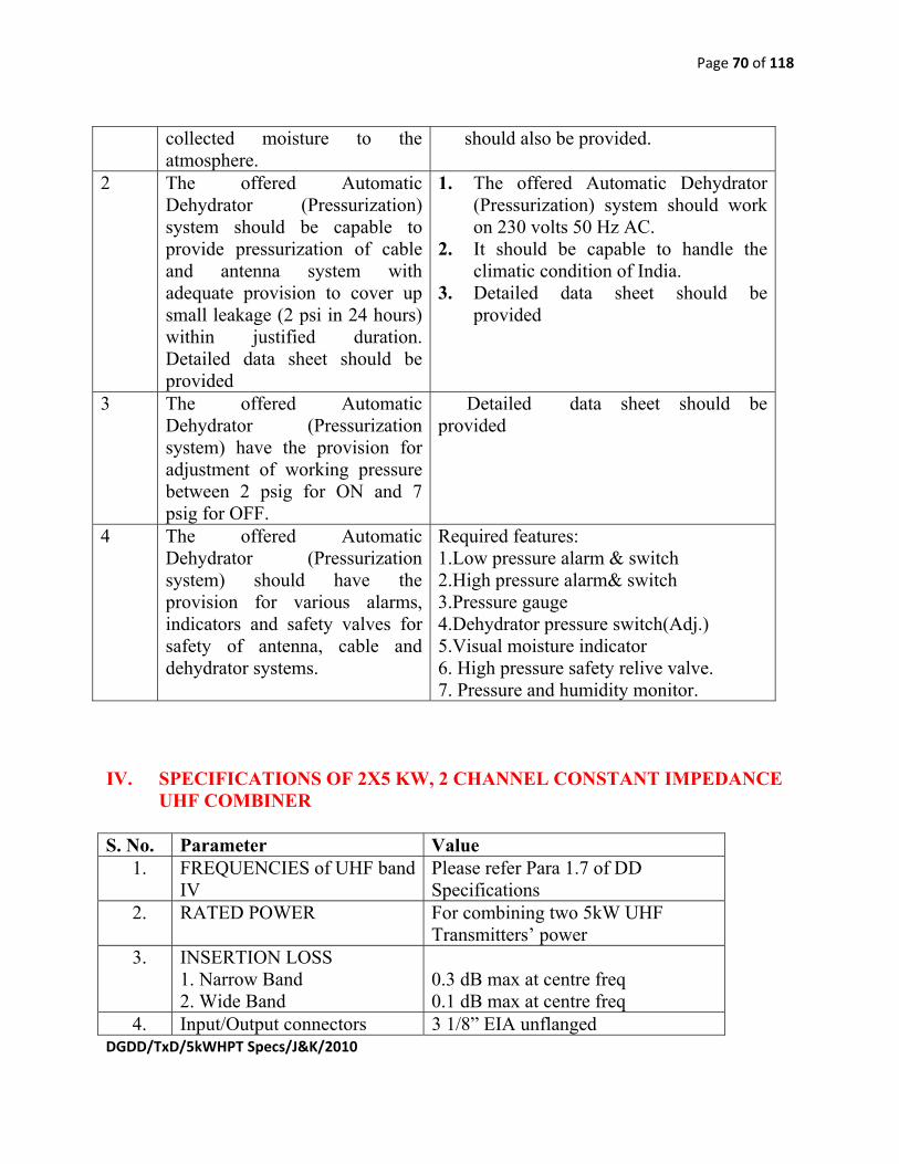
Page 70 of 118
DGDD/TxD/5kWHPT Specs/J&K/2010
collected moisture to the atmosphere.
should also be provided.
2 The offered Automatic Dehydrator (Pressurization) system should be capable to provide pressurization of cable and antenna system with adequate provision to cover up small leakage (2 psi in 24 hours) within justified duration. Detailed data sheet should be provided
1. The offered Automatic Dehydrator (Pressurization) system should work on 230 volts 50 Hz AC.
2. It should be capable to handle the climatic condition of India.
3. Detailed data sheet should be provided
3 The offered Automatic Dehydrator (Pressurization system) have the provision for adjustment of working pressure between 2 psig for ON and 7 psig for OFF.
Detailed data sheet should be provided
4 The offered Automatic Dehydrator (Pressurization system) should have the provision for various alarms, indicators and safety valves for safety of antenna, cable and dehydrator systems.
Required features: 1.Low pressure alarm & switch 2.High pressure alarm& switch 3.Pressure gauge 4.Dehydrator pressure switch(Adj.) 5.Visual moisture indicator 6. High pressure safety relive valve. 7. Pressure and humidity monitor.
IV. SPECIFICATIONS OF 2X5 KW, 2 CHANNEL CONSTANT IMPEDANCE
UHF COMBINER
S. No. Parameter Value 1. FREQUENCIES of UHF band
IV Please refer Para 1.7 of DD Specifications
2. RATED POWER For combining two 5kW UHF Transmitters’ power
3. INSERTION LOSS 1. Narrow Band 2. Wide Band
0.3 dB max at centre freq 0.1 dB max at centre freq
4. Input/Output connectors 3 1/8” EIA unflanged

Page 71 of 118
DGDD/TxD/5kWHPT Specs/J&K/2010
5. VSWR/RETURN LOSS VSWR 1.08:1 at centre frequencyreturn loss 28 dB or better VSWR 1.10:1 at other frequencies return loss 26dB or better in the channel.
6. Isolation 1. Narrow band to Wide Band 2. Wide Band to Narrow Band
30 dB or better 48 dB or better
7. Input Impedance 50 ohm 8. Operating Temperature Range
Cooling 0 to 45 deg C Air convection
9. Weight To be specified by the bidder 10. Dimensions To be specified by the bidder

Page 72 of 118
DGDD/TxD/5kWHPT Specs/J&K/2010
Annexure I-12 SPECIFICATIONS OF SEVEN PORT PATCH PANEL
S.No. Parameter Specification 1.1 FREQUENCY RANGE 470 to 860 MHz 1.2 INPUT /OUTPUT POWER ≥ 5kW/≥10kW 1.3 INPUT / OUTPUT PORTS 3⅛” 1.4 OPERATING TEMPERATURE RANGE -100C to +500C 1.5 Max Altitude 3500 Meter. 1.6 ISOLATION TO UNUSED PORT ≥ 60dB 1.7 INPUT VSWR ≤ 1.05:1 1.8 INSERTION LOSS ≤ 0.1dB 1.10 Forward and reflect power monitoring system To be included in
the offer 1.11 Input, Output, U-Link, Inner Lines 3⅛” unflanged U
links – (Cu Rigid Lines only)
Functions:
1. Accept the output of any UHF TV channel between 470-860 MHz and route the power to the antenna or the dummy load.
2. Provide transmitter interlocks for operational safety. 3. The schematic drawing shown in Annexure III must be referred for
details of U-Links, Power handling and the connections. 4. Provide forward and reflected power monitoring and it’s display for
each transmitter. 5. Provide compact package, which requires minimal maintenance and
immediate and simple installation. 7. The 7 port patch panel shall be mounted vertically on floor. 8. The U link provided should be able to remove and reconnect with minimum effort and should have proper gripping, with locking and unlocking facility.

Page 73 of 118
DGDD/TxD/5kWHPT Specs/J&K/2010
Annexure I-13 SPECIFICATIONS OF 3⅛” / 4” RF FEEDER CABLE
1. Scope:- Doordarshan requires RF Coaxial air dielectric, Feeder cable of size (3⅛” / 4”) for High Power TV Transmitters at Rajauri (J&K) in UHF Band IV/V. The particular R.F. Feeder cable shall be used to feed the R.F. Power output of the TV Transmitters to the input of “TV Transmitting antenna system”. Actual cable length will be intimated at the time of order however feeder cable length may be considered as tentative as given in DD Specification. All RF cables shall be duly pressurized by using Dehydrator (Dehydrator is not the part of the supply). The RF coaxial air dielectric, Feeder cable should be complete in all respect.
2. Technical Specifications 2.1 Jacket Standard Polyethylene black 2.2 Cable Type Air-Dielectric, Corrugated
copper with high density Polyethylene Helix
2.3 Size 3⅛” / 4” dia 2.4 Impedance, ohm 50 +/- 1 ohms 2.5 Maximum Operating Frequency 862 MHz 2.6 Relative Propagation Velocity 93% or better 2.7 Peak Power Rating 800 KW or more 2.8 RF Peak Voltage 9700 Volts or more 2.9 Jacket Spark 8000 Volt RMS or more 2.10 Attenuation at 200 MHz 0.56 dB/100m or less 2.11 Attenuation at 500 MHz 0.94 dB/100m or less 2.12 Attenuation at 800 MHz 1.24 dB/100m or less 2.13 Outer conductor material Corrugated Copper 2.14 Inner Conductor Material Corrugated Copper Tube 2.15 Operating pressure 0.5 bar or more 2.16 Minimum Bending Radius, Single Bend 1270 mm or less 2.17 Cable Weight 3.8 kg/m or less 2.18 Tensile Strength 585 lb or more 2.19 Storage Temperature -40°C to +65° C or better
2.20 Hoisting Stocking Spacing Single value for spacing to be specified by the OEM (Origional Manufacturer)
2.21 Operation Temperature -10° to +50° C or better 2.22 Connectors Each cable length must be
fitted with end connectors

Page 74 of 118
DGDD/TxD/5kWHPT Specs/J&K/2010
(3⅛” EIA flanges) on one end GAS STOP and other end GAS THROUGH. No other connector shall be acceptable.
2..23 Recommended pulling length per hoisting
To be quoted by the bidder
2.24 Mean power rating at 400 C ambient Temperature 200 MHz
35 KW or more
2.25 Mean power rating at 400 C ambient Temperature 500 MHz
21 KW or more
2.26 Mean power rating at 400 C ambient Temperature 800 MHz
16 KW or more
2.27 Wall gland with fitting arrangements to enter the cables from outside the building to inside the building shall be supplied along with the cables
2.28 The 3⅛” flange end GAS STOP connector must be fitted with Schrader valve to connect the cable with De-hydrator.
2.29 All RF cables shall be duly pressurized 2.30 The bidder shall quote for cable with end connectors and other
accessories as per suggestive BOM in Annex-IB GENERAL INSTRUCTIONS TO COMPLETE OFFER: (R.F. Feeder Cable.) 3.1 The details of past supply for the similar RF Feeder Cables should be provided in
the following format:
Name and Postal Address of the Firm
Name of the contact person with E mail id
Telephone and Fax Nos.
Make and Model of the RF Feeder Cables supplied
Power capacity of the similar RF Feeder Cables supplied
Quantity supplied
3.2 The set of essential tool and other necessary equipment should be quoted separately with the offer. 3.3 The RF Feeder Cables manufacturer /bidder must have his local office /
representative in India. The name, contacts, address of local office / representative along with manufacturer’s authority letter in favour of local representative must be given with the offer. The local office / representative in India will be nodal point
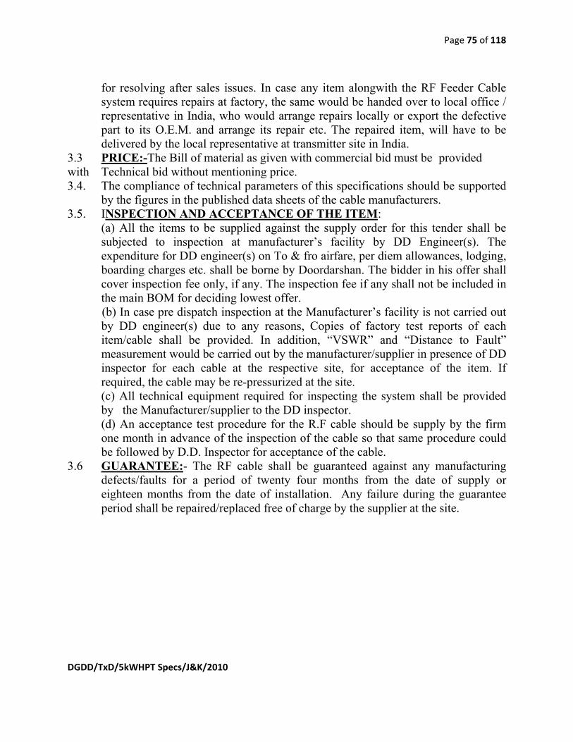
Page 75 of 118
DGDD/TxD/5kWHPT Specs/J&K/2010
for resolving after sales issues. In case any item alongwith the RF Feeder Cable system requires repairs at factory, the same would be handed over to local office / representative in India, who would arrange repairs locally or export the defective part to its O.E.M. and arrange its repair etc. The repaired item, will have to be delivered by the local representative at transmitter site in India.
3.3 PRICE:-The Bill of material as given with commercial bid must be provided with Technical bid without mentioning price. 3.4. The compliance of technical parameters of this specifications should be supported by the figures in the published data sheets of the cable manufacturers. 3.5. INSPECTION AND ACCEPTANCE OF THE ITEM:
(a) All the items to be supplied against the supply order for this tender shall be subjected to inspection at manufacturer’s facility by DD Engineer(s). The expenditure for DD engineer(s) on To & fro airfare, per diem allowances, lodging, boarding charges etc. shall be borne by Doordarshan. The bidder in his offer shall cover inspection fee only, if any. The inspection fee if any shall not be included in the main BOM for deciding lowest offer.
(b) In case pre dispatch inspection at the Manufacturer’s facility is not carried out by DD engineer(s) due to any reasons, Copies of factory test reports of each item/cable shall be provided. In addition, “VSWR” and “Distance to Fault” measurement would be carried out by the manufacturer/supplier in presence of DD inspector for each cable at the respective site, for acceptance of the item. If required, the cable may be re-pressurized at the site.
(c) All technical equipment required for inspecting the system shall be provided by the Manufacturer/supplier to the DD inspector. (d) An acceptance test procedure for the R.F cable should be supply by the firm one month in advance of the inspection of the cable so that same procedure could be followed by D.D. Inspector for acceptance of the cable. 3.6 GUARANTEE:- The RF cable shall be guaranteed against any manufacturing defects/faults for a period of twenty four months from the date of supply or eighteen months from the date of installation. Any failure during the guarantee period shall be repaired/replaced free of charge by the supplier at the site.

Page 76 of 118
DGDD/TxD/5kWHPT Specs/J&K/2010
Annexure I-14 C BAND/KU BAND SATELLITE RECEIVE EQUIPMENT I. Specifications of Professional IRD for C-Band/Ku-Band:
General:
a) The IRD should have a front panel display and one should be able to enter or edit all the parameters for a perfect reception of the signals.
b) There should be provision for observing the BER (Pre & Post correction) of the signal and signal level in the front panel.
c) IRD should be able to descramble BISS mode 1 and BISS-E signals. d) IRD should have at least 10 memory setups to store channels. e) IRD should have CI slot so that by inserting the CAM module signals can be
descrambled.
1. RF Parameters: S. No. Parameter Specification
1. Input Frequency Range 950 - 1750 MHz 2. No. of Inputs 1 No. 3. Tuning Step Size 125 kHz, maximum 4. Satellite Frequency Band C- & Ku-Band, selectable 5. Input Impedance 75 Ohms 6. Input Connector F-Type female 7. Input Power Range -30 to -65 dBm per carrier 8. Image Rejection >30 dB 9. Input Return Loss 7 dB, minimum 10. Noise Figure 20 dB, maximum 11. AFC Tuning Range ± 5 MHz 12. De-Modulation Method QPSK demodulation 13. Variable Symbol Rates 1.5 to 40 M Symbol/sec 14. Convolution Inner FEC
Rates selectable R= 1/2, 2/3, 3/4, 5/6, 7/8, (for QPSK)
15. IF Filter Bandwidth Automatic Selection (dependent on Symbol Rate)
2. Audio and Video Decompression Parameters
S. No. Parameter Specification 1. Video Resolution (all
resolutions shall be capable of I, P & B frame decoding)
720 x 576, 704 x 576, 544 x 576, 480 x 576, 352 x 576 (other standard resolutions should be selectable)

Page 77 of 118
DGDD/TxD/5kWHPT Specs/J&K/2010
2. Video Decompression Type MP @ ML 3. Television Standard PAL-B
Audio Decompression Type MPEG-layer-2 (Stereo/Musicam, i.e. Single Mono, Dual Mono, Stereo, and Joint Stereo)
3. Transport Stream O/P: MPEG-2 ASI on BNC 4. Video Output Specifications:
i. Analog Video Output Specifications S. No. Parameter Specification (a) Connector Type BNC (75 Ohms) (b) Quantity 1 No. of analog composite PAL-B
CCIR Standard (one main and one for monitoring)
(c) Level 1.0 V p-p +/- 5% ii. Digital Video Output Specifications
S. No. Parameter Specification (a) Connector Type BNC (75 Ohms) (b) Quantity 1 No. of DIGITAL output compliant
to ITU-R BT.656 Standard (c) Level 800mV p-p for SDI iii. Video Performance Specifications
S. No. Parameter Specification (a) Frequency Response Within 2 dB down at 5 MHz (b) Chroma-Luma Delay ±30 ns, maximum (c) Field Time Distortion < 2% (d) Line Time Distortion < 1% (e) Short Time distortion < 2% (f) Differential Gain < 4% (g) Differential Phase < 2° (h) Signal to Noise Ratio >55 dB (luminance weighted)

Page 78 of 118
DGDD/TxD/5kWHPT Specs/J&K/2010
iv. VBI Signal Reinsertion Specifications:
S. No. Parameter Specification (a) VBI Formats Supported WST
VITC (b) Range of VBI lines Field 1 lines 7 to 22 (PAL) and
corresponding lines of Fi2ld 2 (c) Synchronisation with
Video Within ± 1 frame
(d) Preservation of line numbering
VBI data shall be reinserted on the original line number
5. Audio Output 5.1 Analog Audio: a) Each analog audio output shall be presented as a stereo pair. b) In the event of “Mono” transmissions, the same encoder input channel will be output to both left and right connectors. c) In other modes (“Stereo”, “Joint Stereo” and “Dual Mono”), the two encoder input channels will be output as left and right. d) Means shall be provided to combine the left and right channels on the IRD output to produce a mono output from stereo transmissions to accommodate those sites not equipped for stereo transmission.
5.1.1 Analog Audio Output Specifications S. No. Parameter Specification (a) Output Impedance 600Ω (balanced) (b) Number of Outputs 4, configurable as Stereo, Joint
Stereo, Single mono, Dual mono. (c) Connector Type XLR Male Socket or with suitable XLR
Adapter (i.e., no terminal block)
5.2 Digital Audio Output Specifications
S. No. Parameter Specification (a) Output level 5 Volts nominal (b) Output Format AES/EBU
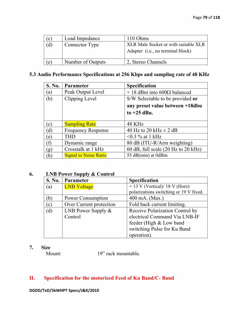
Page 79 of 118
DGDD/TxD/5kWHPT Specs/J&K/2010
(c) Load Impedance 110 Ohms (d) Connector Type XLR Male Socket or with suitable XLR
Adapter (i.e., no terminal block)
(e) Number of Outputs 2, Stereo Channels
5.3 Audio Performance Specifications at 256 Kbps and sampling rate of 48 KHz
S. No. Parameter Specification (a) Peak Output Level + 18 dBm into 600Ω balanced (b) Clipping Level S/W Selectable to be provided or
any preset value between +18dbu to +25 dBu.
(c) Sampling Rate 48 KHz (d) Frequency Response 40 Hz to 20 kHz ± 2 dB (e) THD <0.3 % at 1 kHz (f) Dynamic range 80 dB (ITU-R/Arm weighting) (g) Crosstalk at 1 kHz 60 dB, full scale (20 Hz to 20 kHz) (h) Signal to Noise Ratio 55 dB(min) at 0dBm
6. LNB Power Supply & Control S. No. Parameter Specification (a) LNB Voltage + 13 V (Vertical)/ 18 V (Horz)
polarizations switching or 19 V fixed. (b) Power Consumption 400 mA. (Max.) (c) Over Current protection Fold back current limiting. (d) LNB Power Supply &
Control Receive Polarization Control by electrical Command Via LNB-IF feeder (High & Low band switching Pulse for Ku Band operation).
7. Size
Mount: 19” rack mountable. II. Specification for the motorized Feed of Ku Band/C- Band

Page 80 of 118
DGDD/TxD/5kWHPT Specs/J&K/2010
1. Focus : Prime/offset focus, 2. Frequency : Ku- band / C- band 3. Ports : 2 ports, for receiving both linear and
Orthogonal polarization signals 4. Polarization discrimination : 30 dB ( min ) 5. Polarization Adjustment : -5degree to 95 degree
III. Specifications for Cables & Connectors
An interconnecting low loss cable of length of 75 meters is required with the 6.2 M PDA. The cable should be quoted in denomination of 50m & 25m, which can be used independently (i.e. as 50m or 25m) or collectively i.e. as a 75m length using a coupler (I-Connector) in between the 50m & 25m cables between outdoor and indoor units. The total insertion Loss for cable should not exceed 15dB at 1450 MHz. Two sets of cables are to be quoted. IV. Specifications for Parabolic Dish Antenna, solid type, 2.4 M (dia)
S. No. Parameter Specification (a) Antenna type Offset / Prime Focus (b) Frequency 10.7 GHz to 12.75 GHz (c) Size
2.4 m diameter
(d) 3dB beam width Better than 1º (e) Aperture efficiency Better than 70% (f) Gain at 11.7 GHz Better than 47 dB (min) (g) Drive system steerability Manual (h) Azimuth 0 to 3600 continuous with fine
adjustments (i) Elevation 10 deg to 85 deg (j) Feed Prime focus, 2 port, for receiving
both linear orthogonal polarized signal.
(k) Polarization Linear orthogonal (l) Mount option Pole Az-El and Pole wall to be
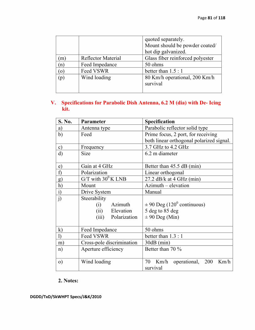
Page 81 of 118
DGDD/TxD/5kWHPT Specs/J&K/2010
quoted separately. Mount should be powder coated/ hot dip galvanized.
(m) Reflector Material Glass fiber reinforced polyester (n) Feed Impedance 50 ohms (o) Feed VSWR better than 1.5 : 1 (p) Wind loading
80 Km/h operational, 200 Km/h survival
V. Specifications for Parabolic Dish Antenna, 6.2 M (dia) with De- Icing
kit.
S. No. Parameter Specification a) Antenna type Parabolic reflector solid type b) Feed Prime focus, 2 port, for receiving
both linear orthogonal polarized signal.c) Frequency 3.7 GHz to 4.2 GHz d) Size
6.2 m diameter
e) Gain at 4 GHz Better than 45.5 dB (min) f) Polarization Linear orthogonal g) G/T with 300 K LNB 27.2 dB/k at 4 GHz (min) h) Mount Azimuth – elevation i) Drive System Manual j) Steerability
(i) Azimuth (ii) Elevation (iii) Polarization
± 90 Deg (1200 continuous)
5 deg to 85 deg ± 90 Deg (Min)
k) Feed Impedance 50 ohms l) Feed VSWR better than 1.3 : 1 m) Cross-pole discrimination 30dB (min) n) Aperture efficiency
Better than 70 %
o) Wind loading
70 Km/h operational, 200 Km/h survival
2. Notes:

Page 82 of 118
DGDD/TxD/5kWHPT Specs/J&K/2010
2.1 The structural analysis may be provided from structural engineer to asses the strength. 2.2 A calibrated graduation of Azimuth, Elevation and Polarization offset should be provided in the antenna.
VI. Specifications for the Digital LNBC in C band 1. Technical Specifications: S. No. Parameter Specification
a) Input frequency range 3.4 GHz to 4.2 GHz b) Local Oscillator frequency 5.150 GHz c) L.O. Stability
L.O. Phase noise ± 25 KHz or better Better than 90 dBc/Hz @ 100kHz (min)
d) Output frequency 950 MHz to 1750 MHz e) Conversion gain 60 dB (min.) f) Gain response Better than ± 0.5 dB/40 MHz g) Output level at 1dB
compression point 3 dBm
h) Output Connector F type female i) Input VSWR/Output VSWR Better than 2:1 j) Noise Temperature Better than 30deg K k) Power supply requirement Should work between + 15V to +24V
l) Input flange CPR 229 m) Lightening/Surge protection Should be provided
2. LNBC should be environmentally sealed against weather conditions and extremes of temperature (-10ºC to 50 ºC). LNBC should also be 100% water proof.
VII. SPECIFICATION for the Digital LNBC in Ku band 1. Technical Specifications: S. No. Parameter Specification
a) Input frequency range 10.95 GHz to 11.7 GHz 11.7 GHz to 12.2 GHz
b) Local Oscillator frequency LO freq of LNBC should be capable to provide output frequency of LNBC between 950 to 2150MHz.
c) L.O. Stability L.O. Phase noise
± 100 KHz or better Better than 75 dBc/Hz @ 1kHz
d) Output frequency 950 MHz to 1450 MHz
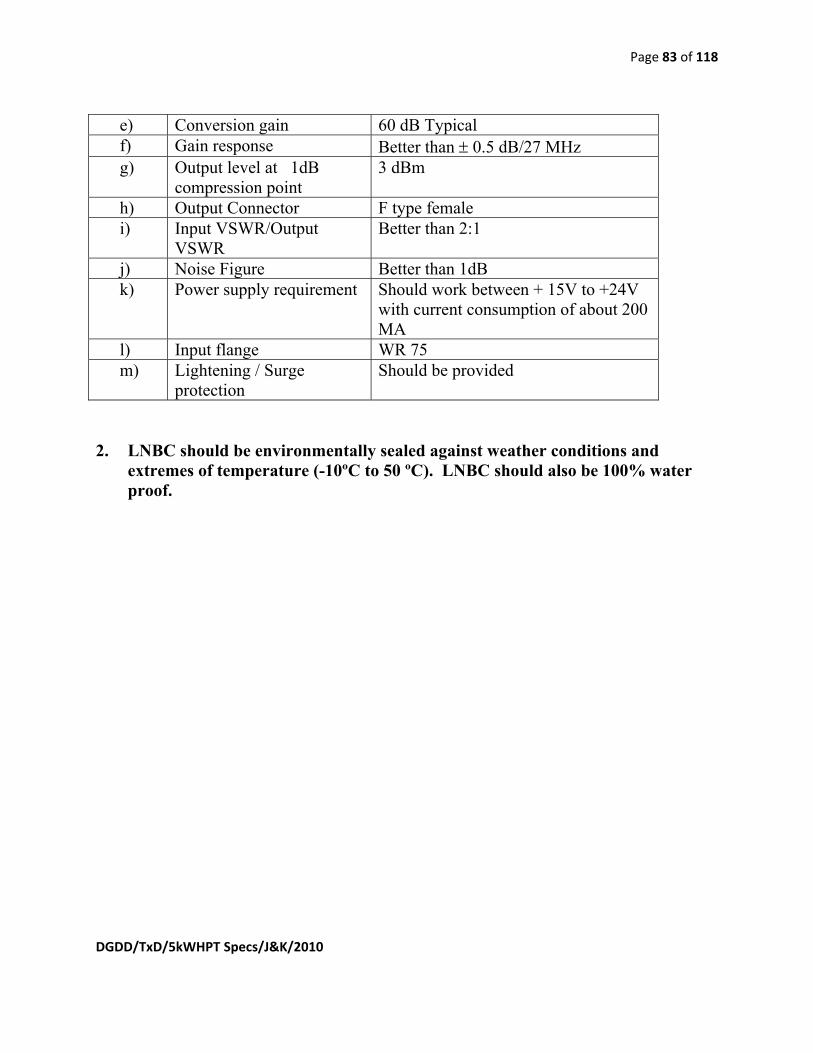
Page 83 of 118
DGDD/TxD/5kWHPT Specs/J&K/2010
e) Conversion gain 60 dB Typical f) Gain response Better than ± 0.5 dB/27 MHz g) Output level at 1dB
compression point 3 dBm
h) Output Connector F type female i) Input VSWR/Output
VSWR Better than 2:1
j) Noise Figure Better than 1dB k) Power supply requirement Should work between + 15V to +24V
with current consumption of about 200 MA
l) Input flange WR 75 m) Lightening / Surge
protection Should be provided
2. LNBC should be environmentally sealed against weather conditions and
extremes of temperature (-10ºC to 50 ºC). LNBC should also be 100% water proof.

Page 84 of 118
DGDD/TxD/5kWHPT Specs/J&K/2010
Annexure I-15 SPECIFICATIONS FOR 80KVA (1+1) STAND ALONE, SELF CONTAINED, WATER COOLED SILENT TYPE DIESEL GENERATOR SET GENERAL: The Stand Alone, Self Contained in a weather proof enclosure canopy, Silent type water cooled Diesel Generator set of 80 KVA capacity (at site condition), 415 V, 3 phase, 50 Hz, 4 wire is required for TV transmitters at Rajauri (J&K). SUMMARY :
1. Section - I: General (General conditions governing the supply.) 2. Section - II: Technical Specifications .
SECTION-I:
1. GENERAL
1.1 Scope: This section covers the general conditions governing the design, supply, factory testing, transportation to site, Installation, Testing, and Commissioning satisfactory operation of DG Set at the site .
1.2 Location : The Stand alone, Self Contained in weather proof canopy Silent type Water cooled
DG set will be installed on cement concrete platform for outdoor application. 1.3 General Conditions : 1.3.1 The DG SET should generally conform to the technical specifications in Section -
II. Should a bidder, however, desire to depart in any respect from the given specifications either on account of manufacturing practice or for any other reasons, he must specifically point out the modifications explaining in detail each and every departure he proposes to make.
1.3.2 The DG Set should be designed for efficient and trouble free service for 24x7 hrs.
of continuous operation at a stretch. All materials used in the manufacture should be conform to the IS: 10002-1981 and 13364(Part-2)-1992 amended to date.
1.3.3 All work should be carried out in accordance with standard mechanical &
electrical practice. The units should be designed for ease in operation, maintenance and complete safety to operating personnel.
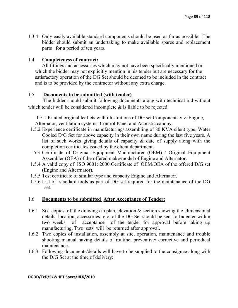
Page 85 of 118
DGDD/TxD/5kWHPT Specs/J&K/2010
1.3.4 Only easily available standard components should be used as far as possible. The bidder should submit an undertaking to make available spares and replacement parts for a period of ten years.
1.4 Completeness of contract:
All fittings and accessories which may not have been specifically mentioned or which the bidder may not explicitly mention in his tender but are necessary for the satisfactory operation of the DG Set should be deemed to be included in the contract and is to be provided by the contractor without any extra charge.
1.5 Documents to be submitted (with tender) The bidder should submit following documents along with technical bid without which tender will be considered incomplete & is liable to be rejected.
1.5.1 Printed original leaflets with illustrations of DG set Components viz. Engine, Alternator, ventilation systems, Control Panel and Acoustic canopy.
1.5.2 Experience certificate in manufacturing/ assembling of 80 KVA silent type, Water Cooled D/G Set for above capacity in their own name during the last five years. A list of such works giving details of capacity & date of supply along with the completion certificates issued by the client department.
1.5.3 Certificate of Original Equipment Manufacturer (OEM) / Original Equipment Assembler (OEA) of the offered make/model of Engine and Alternator.
1.5.4 A valid copy of ISO 9001: 2000 Certificate of OEM/OEA of the offered D/G set (Engine and Alterrnator).
1.5.5 Test certificate of similar type and capacity Engine and Alternator. 1.5.6 List of standard tools as part of DG set required for the maintenance of the DG
set. 1.6 Documents to be submitted After Acceptance of Tender: 1.6.1 Six copies of the drawings in plan, elevation & section showing the dimensional
details, location, accessories etc. of the DG Set should be sent to Indenter within two weeks of acceptance of the tender for approval before taking up manufacturing. Two sets will be returned after approval.
1.6.2 Two copies of installation, assembly at site, operation, maintenance and trouble shooting manual having details of routine, preventive/ corrective and periodical maintenance.
1.6.3 Following documents/details will have to be supplied to the consignee along with the D/G Set at the time of delivery:
Page 86 of 118
DGDD/TxD/5kWHPT Specs/J&K/2010
a) Two copies of the book of instructions for the Installation, Testing, Commissioning, Operation and Maintenance of DG Set.
b) Factory Test Certificates showing the results of tests actually conducted on the Engine, Alternator & Accessories.
c) Two sets of finalized drawings showing dimensions and other fixtures on the DG Set. including wiring of panel.
1.6.4 Two set of drawing and Manuals/instruction book-let etc of DG Set should be sent directly to Director Engineering (Transmitter Design), DG:DD, Doordarshan Bhavan, Copernicus Marg, New Delhi-110001, as soon as drawings are approved by the Indenter.
1.8 PACKING The packing should be suitable to withstand transportation hazards. Each packing
should contain a packing slip giving the details of the contents and bear the address of consignee. A copy of packing slip giving the list of items included in the package together with the package number should be mailed in advance to the consignee.
1.9 GUARANTEE: The DG Set should be guaranteed in all respects for satisfactory operation under
full load condition for one year from the date of taking it into service.
1.10 INSTALLATION: The supplier is required to SITC (Supply, Installation, Testing & Commissioning) tender/works. All internal wiring jobs including the supply of Main Cable from Alternator to Control Panel should be done by bidder.
1.11 SPARES: Along with the diesel generator, the Bidder should also quote separately for
recommended spares for two years operation of DG set giving list of all the spares alongwith price of each item of spare by considering that DG set will be running continuously for at least 12 hrs. per day . The list of recommended spares should be based upon field reports and should be sufficient enough for trouble free operation of the DG Set at remote locality.
1.12 MISC. CONDITIONS: 1.12.1The supplier should make good/repair the damage to indentor building during
installation, testing etc. of the DG set.

Page 87 of 118
DGDD/TxD/5kWHPT Specs/J&K/2010
1.12.2The supplier should hold indentor or it’s representative harmless for any liability/ compensation by his employee or third party for any damage/ loss of life or property to them during the execution of project.
1.12.3Supplier/ his installation crew will make their own arrangement for stay during installation of DG set.
1.12.4Supplier will comprehensively insure entire martial for loss/theft till installation is completed and handed over to the consignee. Policy in this regard should be submitted along with initial consignment.
1.14. TESTING/ACCEPTANCE AT SITE: The supplier should show all the required tests at site as per mutually agreed
acceptance procedure according to relevant standard of BIS for such jobs at no load, partial load and full load (in steps of 20% from no load to full load). The consumable items like fuel, lubricants, belts etc. during this testing should be arranged by the bidder.
1.15. C E A CLEARANCE: The supplier should have to arrange CEA clearance for DG set before the same is
offered for acceptance to indentor at site. SECTION_-_II 2. TECHNICAL SPECIFICATIONS The stand alone, silent type, Water Cooled, D/G set mounted on a self contained rust proof chassis complete with weather proof, sound proof Acoustic enclosure with built in exhaust & ventilation system. D/G Set should meet the noise level. All units & accessories should be housed on single chassis inside the enclosure. 2.1 ALTERNATOR :The Alternator will conform to IS : 13364 (Part - 2) – 1992 for
manufacturing , Enclosure of alternator as per IS : 4691 IP 23, mounting as per IS : 2253 & testing of Alternator as per relevant IS with latest amendments. The Alternator must be of ISO certified manufacturer like KEC / STAMFORD/ AVKC.
S. No. Item DD’s Requirement Bidders Offer 2.1.1 Electrical Output
(Prime Power) 80 KVA at site conditions
2.1.2 Make To be indicated by bidder. 2.1.3 No.of phases &
interconnection between 3 phase with Neutral point in terminal box, Star Connected

Page 88 of 118
DGDD/TxD/5kWHPT Specs/J&K/2010
phases if any 2.1.4 Rated Voltage 415 V (Nominal) 2.1.5 Voltage regulation + 1.0 % from no load to full load
at lagging power factor of 0.8 to 1.0 and speed drop of less than or equal to 4%
2.1.6. Power Factor Better than 0.85 (lagging) 2.1.7. Frequency in Hz 50 Hz + 4 % 2.1.8 Speed in RPM at rated load 1500 RPM 2.1.9 Type of coupling Alternator to be coupled either
directly to engine or through flexible rubber coupling on a common fabricated base frame
(I) The alternator should be self regulated, self excited and rated for continuous operation from no load to full load under all working conditions.
2.1.10 Exciter
(II) The alternator should be able to supply unbalanced load as specified in IS : 13364 (Part-2) : 1992 with latest amendments.
2.1.11 Exciter rating It should be rated for 1.25 times the full load conditions
2.1.12 Earthing As per IS:3043 – 1987 amended to date
2.1.13 Type of load to be connected i. Broadcasting Transmitter load instantaneously and continuously varying above a specified limit.
ii. Building light, Flood lights and Power Loads.
2.1.15 Type of Duty Continuous 2.1.16 Type of Field Rotating 2.1.17
Class of Insulation Class 'H'
2.1.18 Construction Horizontal, foot mounted with ball or roller bearing and end shields
2.1.19 Cooling Machine should have cooling provision as per IS : 6362 - 1971 IC 01 amended to date
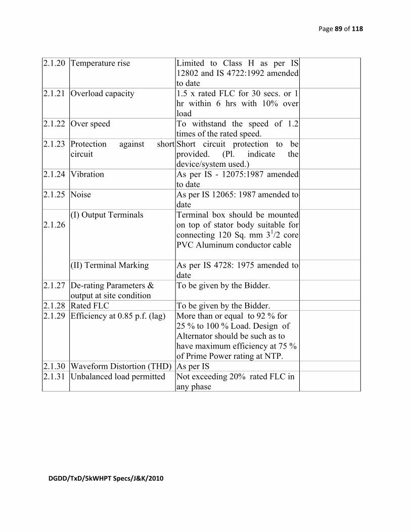
Page 89 of 118
DGDD/TxD/5kWHPT Specs/J&K/2010
2.1.20 Temperature rise Limited to Class H as per IS 12802 and IS 4722:1992 amended to date
2.1.21 Overload capacity 1.5 x rated FLC for 30 secs. or 1 hr within 6 hrs with 10% over load
2.1.22 Over speed To withstand the speed of 1.2 times of the rated speed.
2.1.23 Protection against short circuit
Short circuit protection to be provided. (Pl. indicate the device/system used.)
2.1.24 Vibration As per IS - 12075:1987 amended to date
2.1.25 Noise As per IS 12065: 1987 amended to date
(I) Output Terminals Terminal box should be mounted on top of stator body suitable for connecting 120 Sq. mm 31/2 core PVC Aluminum conductor cable
2.1.26
(II) Terminal Marking As per IS 4728: 1975 amended to date
2.1.27 De-rating Parameters & output at site condition
To be given by the Bidder.
2.1.28 Rated FLC To be given by the Bidder. 2.1.29 Efficiency at 0.85 p.f. (lag) More than or equal to 92 % for
25 % to 100 % Load. Design of Alternator should be such as to have maximum efficiency at 75 % of Prime Power rating at NTP.
2.1.30 Waveform Distortion (THD) As per IS 2.1.31 Unbalanced load permitted Not exceeding 20% rated FLC in
any phase

Page 90 of 118
DGDD/TxD/5kWHPT Specs/J&K/2010
2.2 DIESEL ENGINE
S. No. Item DD's Requirement Bidder Offer 2.2.1 Type of engine Self-start, 4 stroke, Turbo-charged 2.2.2 Make To be indicated by tenderder 2.2.3 Capacity i. To be rated for continuously driving the
alternator to deliver the rated full load output at site condition . ii. The Bidder should specify the capacity of the Diesel Engine offered by him alongwith the computations of various de-rating applied as per relevant IS.
2.2.4 Type of fuel H.S. Diesel Oil 2.2.5 Method of Cooling i. Water-cooled with Radiator.
ii. Provision for anti-rusting, anti-corrosion & anti freeze arrangement for water coolant is to be provided, if applicable. iii. Jacket Water system should be free from rubber hoses for reducing the risk of leakage and therefore engine failure. iv. Cooling System should be provided with Twin Thermostats, permanent lubricated water pump.
2.2.6 Method of starting i. The Engine should be cold starting type. ii. It should be battery started iii) Starting switch with key should be provided on engine control panel. Starting motor with battery charging alternator alongwith voltage regulator and activation switch should be integral part of the starting system. iv) One Ammeter should also be provided in the battery Charging circuit. v) Battery offered should be maintenance free tubular electrode type of standard

Page 91 of 118
DGDD/TxD/5kWHPT Specs/J&K/2010
2.2.8 Speed of Engine
1500 RPM with class A1 governing as laid down in IS-10000.
2.2.9 Type of Exhaust system
A heavy-duty residential type exhaust silencer to be provided.
2.2.10 i) The Engine should be protected against High water temp. with audio & visual alarm.
ii) Over speed protection through hour meter cum RPM indicator with Audio and visual alarm.
Engine protection
iii) Low Lubricating Oil Pressure Protection with audio and visual Alarms.
2.2.11 Accessories for Engine
Standard Accessories
2.2.12 Vibration Insulation Anti-Vibration Pad of Polybond/ Resinoflex make should be provided.
2.2.12 Base frame Common MS channel fabricated, rigid, rust proof & with suitable anti-vibration mounting.
2.2.13 Consumption of fuel and lubricant(Ltrs/ hrs) The Bidder will submit this data at site condition.
At Site Conditions: (a) …………. lts/hr at 25 % load. (b) …………. lts/hr at 50 % load. (c) …………. lts/hr at 75 % load. (d) …………..lts/hr at 100 % load.
2.2.14 Lub. oil specification As per IS 2.2.15 Total lubrication
system capacity To be given by the Bidder
2.2.16 Total coolant capacity
To be given by the Bidder
make like EXIDE/STANDARD FURUKAWA etc. and complete with charging connecting leads, & terminals. The Ampere hour rating and no. of plates of battery should be indicated.
2.2.7 Capacity of fuel tank Service Tank of capacity with suitable dial type fuel gauge (NB: Tank should be part of self-contained cabinet & housed suitably.)

Page 92 of 118
DGDD/TxD/5kWHPT Specs/J&K/2010
2.2.17 Fuel system Direct fuel injection system with fuel lift pump inline type.
2.2.18 Exhaust Gas Volume To be given by the Bidder at 75 % and 100 % prime Power rating
2.2.19 Exhaust Gas Temp. To be given by the Bidder at 75 % and 100 % prime Power rating
2.2.20 Smoke Level Harmful Gaseous emission should meet the Pollution Board norms for Environment protection.
2.2.21 Regulation As per IS 2.3 COMPLETE DIESEL GENERATOR SET :
S. No.
Item
DD's Requirement
Bidder Offer
2.3.1. Type of DG set Silent ,Self contained, Standalone with acoustic
enclosure.
(a) Length : To be given by the Bidder (b) Width : To be given by the Bidder
2.3.2. Dimensions of D/G Set including Acoustics Enclosure
(c) Height : To be given by the Bidder.
2.3.3. Total Weight of D/G Set
To be given by the Bidder.
2.3.4. Type of Enclosure DG set should be housed in a Acoustic Enclosure consisting of Acoustic Insulation, Non-inflammable, Canopy Ventilation System with CFM details , doors and suitable for outdoor use.
2.3.5. Noise level Complete D/G set including Engine should meet the Pollution Board norms as per IS
2.3.6. Smoke Level Harmful Gaseous emission level should meet the Pollution Board norms for Environment protection at the time of delivery of DG set.( Original certificates to be enclosed from authorized agency)
2.3.7 Exhaust pipe Exhaust pipe as per IS latest instruction of Pollution board.

Page 93 of 118
DGDD/TxD/5kWHPT Specs/J&K/2010
2.3.8. EARTHING
As per IS
2.4 ENGINE AND ALTERNATOR CONTROL PANEL S.No.
DD’s REQUIREMENT
Bidder’s Offer
2.4.1 Control panel for 415 V 3-phase, 50 Hz , 4wire AC supply should have following features & accessories.
i. It should be mounted on the enclosure with hinged panel and will be wired up as per standard practice & as per I.E. rules.
ii. It should be fabricated out of CRCA SHEET duly processed in 7 tank, dust proof, vermin proof & power coated.
iii. The Alternator panel is to be provided with 200 Amp (Draw out type) 4 Pole ACB & adequate space for connecting outgoing & incoming as per IS . The rating of ACB/ contactors/ relays will be suitable for 80 KVA and rating of interconnecting copper cables should be suitable for taking at least 1.5 time the rated current.
2.4.2. The Panel should comprise of following Instruments : (a) Start/Stop switch with key (b) Local/Remote control switch (c) Frequency meter (d) DC Voltmeter & Ammeter for battery charging (e) AC Voltmeter (Flush type) with Selector switch (f) kW meter, pf meter, (g) Ammeter (Flush type) having scale more than 20% full load
current with selector switch (h) Instrument fuses/ MCBs (i)Low oil pressure & high water temp. Audio alarm. (j) Priming pump starter(k) Hour meter (l) RPM meter (Tachometer) (m) KWH meter

Page 94 of 118
DGDD/TxD/5kWHPT Specs/J&K/2010
2.4.3. The Panel should comprise of following Indications : (a) Set ON (b) Load ON (c )Remote control (d) Low Lubricating oil
pressure (e) Over speed (f) High Enclosure temp. (g) High water Temp.
2.4.4. PROTECTION : FOR GENERATOR : (A) ALTERNATOR: i) Earth fault protection through relay. ii) Under voltage protection through relay. iii) Under frequency protection through relay. iv) Over current (through MCCB/ACB release)
v) One set of fuses should be provided for instruments & control
circuit. (B) ENGINE: i) Protection against following a. Engine Over speed b. Low Lube Oil pressure
c. High water Temp. ii) One set of audio and visual Alarm for above protection.
2.4.5.
The Engine Local Control Panel should have following features a) Start/stop push button with key for local starting. b) Special switch (or any other method) on the local control panel providing locking in any of the three positions- i. Remote ii. Local iii. Off-No rotation at all. c) A timer to ensure that the starter is not pressed for a long time. d) A pressure switch to ensure that the starting motor is not energized, when the generator is running.
e) Lubricant Oil Temp. gauge f) Hour cum Tachometer
2.4.6. Power supply for Space Heaters of Engine : Suitable arrangement through push buttons should be made for power supply to Space heaters from the battery of DG set. The Ampere Hour rating of the battery may be offered accordingly.

Page 95 of 118
DGDD/TxD/5kWHPT Specs/J&K/2010
Annexure I-16
SPECIFICATIONS OF 60 KVA 3 PHASE INPUT 3 PHASE OUTPUT UPS SYSTEM ALONGWITH ISOLATION TRANSFORMER FOR TV
TRANSMITTERS
1.0 GENERAL:
1.1 Doordarshan requires Uninterrupted Power Supply System (UPS System IN 1+1 MODE) for backup Power Supply for its High Power TV Transmitters. The UPS should be reliable and stable in operation under Indian tropical conditions. This Specification describes a 60 KVA three-phase, True on-line double conversion continuous operation (defined as VFI in the IEC62040-3 UPS Specifications), solid-state Uninterruptible Power Supply. The UPS system shall be capable of running in single stand-alone Module with 15 minutes back up time at full rated capacity. All connectors & cables etc. required for UPS System & its installation should be supplied with the equipment. The UPS System quoted must conform to the latest international standards of safety and EMC. The conformance to such standards (indicating standard’s name & number) must be stated in compliance statement. The UPS and battery manufacturer must be ISO 9001-2008 certified for manufacturing of UPS and battery (respectively). A copy of the valid ISO 9001-2008 certificate should be enclosed with the offer.
1.2 The capacity “60KVA” may be treated as suggestive. However, it is the responsibility of the bidder to calculate the exact capacity of the UPS and consequently the requirement of battery bank for 15 minutes back up, taking into consideration the load of transmitter, cooling system, input monitoring, measuring equipment and any other auxiliary equipment as part of the system with necessary margin for calculating the capacity of the UPS.
1.3 All the other technical specifications paras and sub paras are to be complied.
2. TECHNICAL SPECIFICATIONS OF UPS SYSTEM: 2.1 The UPS shall produce high quality sinusoidal output. The UPS shall be designed to operate as true on-line, double conversion type UPS strictly as per the definition of IEC 62040-3 as follows: 2.1.1 Normal Operation:
The critical AC load should be continuously supplied by the UPS inverter. The rectifier & charger should take power from the AC input source, covert it into suitable DC and supply to the inverter as well as charge the Batteries on Automatic Float cum Boost Mode.

Page 96 of 118
DGDD/TxD/5kWHPT Specs/J&K/2010
2.1.2 Upon Mains Failure: Upon failure of AC input power, the critical AC load should continue to be
supplied by the inverter, which should obtain power from the battery. There shall be no interruption in power to the critical load upon failure or restoration of the AC input source. 2.1.3 Upon Mains Restoration:
Upon restoration of AC input power, the Rectifier/Charger should automatically restart walk-in and gradually take-over the supply to inverter and charging to the battery. 2.1.4 Static Bypass:
Each UPS Module should have in-built 100% rated static Bypass Line. 2.3 Static Transfer Switch: Static Transfer Switch and bypass circuit shall be provided as an integral part of the UPS. The static switch shall be naturally commutated high-speed static (SCR Type) device rated to conduct upto 135% of full load current, continuously.
The Overload withstanding capability of Static Bypass Path should be 1000% for 100 millisecond, 135% - 170% for 10 minutes.
2.4 Maintenance Bypass Isolator: 2.4.1 General: A manually operated maintenance bypass isolator shall be incorporated into the each UPS cabinet to directly connect the critical load to the input AC power source, bypassing the rectifier/charger, inverter, and static transfer switch. 2.4.2 Maintenance Capability: With the critical load powered from the maintenance bypass circuit, it shall be possible to check out the operation of the rectifier/charger, inverter, battery, and static transfer switch. 2.5 Technical Specifications: 2.5.1 System continuous rating 60 KVA, 48 KW at 0.8 power factor. 2.5.2 Battery Capacity: The UPS system must be capable of providing supply to the UPS Inverter/s on 60 KVA/48 KW load for minimum 15 minutes of battery back-up time. The Battery Bank shall be MF-VRLA type (Make GNB/ Amara Raja/ HBL Nife) consisting of 2 V cells installed in proper standard cabinets with proper connections and in factory charged condition. The battery calculation is as follows: BATTERY SIZING CALCULATION GUIDELINE (FOR VRLA BATTERIES)
Type of Battery : Maintenance Free Valve Regulated Lead Acid With 20
Year Design Life (Amara Raja/HBL Nife/GNB Make). Nominal DC Bus Voltage : X V DC Nominal Cell Voltage : 2 V per cell
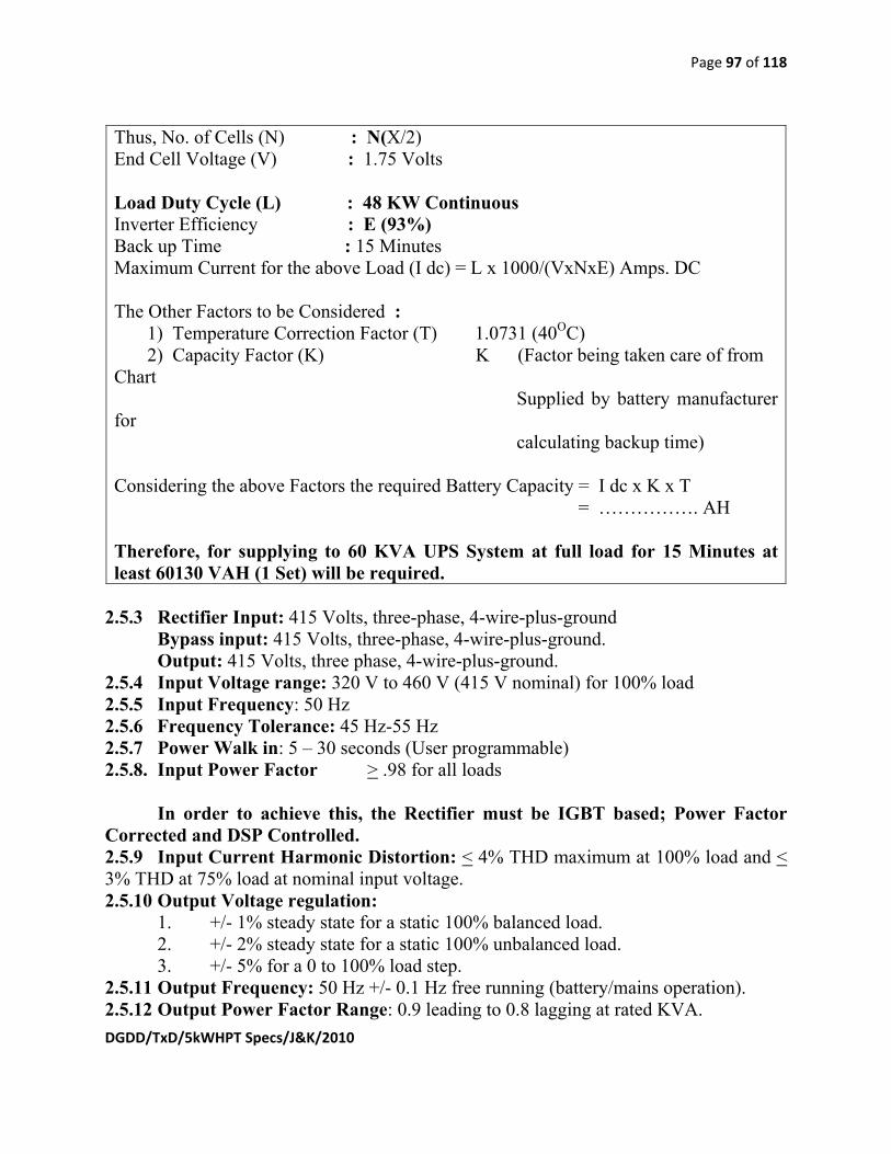
Page 97 of 118
DGDD/TxD/5kWHPT Specs/J&K/2010
Thus, No. of Cells (N) : N(X/2) End Cell Voltage (V) : 1.75 Volts Load Duty Cycle (L) : 48 KW Continuous Inverter Efficiency : E (93%) Back up Time : 15 Minutes Maximum Current for the above Load (I dc) = L x 1000/(VxNxE) Amps. DC The Other Factors to be Considered : 1) Temperature Correction Factor (T) 1.0731 (40OC) 2) Capacity Factor (K) K (Factor being taken care of from Chart Supplied by battery manufacturer for calculating backup time) Considering the above Factors the required Battery Capacity = I dc x K x T = ……………. AH Therefore, for supplying to 60 KVA UPS System at full load for 15 Minutes at least 60130 VAH (1 Set) will be required.
2.5.3 Rectifier Input: 415 Volts, three-phase, 4-wire-plus-ground
Bypass input: 415 Volts, three-phase, 4-wire-plus-ground. Output: 415 Volts, three phase, 4-wire-plus-ground.
2.5.4 Input Voltage range: 320 V to 460 V (415 V nominal) for 100% load 2.5.5 Input Frequency: 50 Hz 2.5.6 Frequency Tolerance: 45 Hz-55 Hz 2.5.7 Power Walk in: 5 – 30 seconds (User programmable) 2.5.8. Input Power Factor > .98 for all loads
In order to achieve this, the Rectifier must be IGBT based; Power Factor
Corrected and DSP Controlled. 2.5.9 Input Current Harmonic Distortion: < 4% THD maximum at 100% load and < 3% THD at 75% load at nominal input voltage. 2.5.10 Output Voltage regulation:
1. +/- 1% steady state for a static 100% balanced load. 2. +/- 2% steady state for a static 100% unbalanced load. 3. +/- 5% for a 0 to 100% load step.
2.5.11 Output Frequency: 50 Hz +/- 0.1 Hz free running (battery/mains operation). 2.5.12 Output Power Factor Range: 0.9 leading to 0.8 lagging at rated KVA.
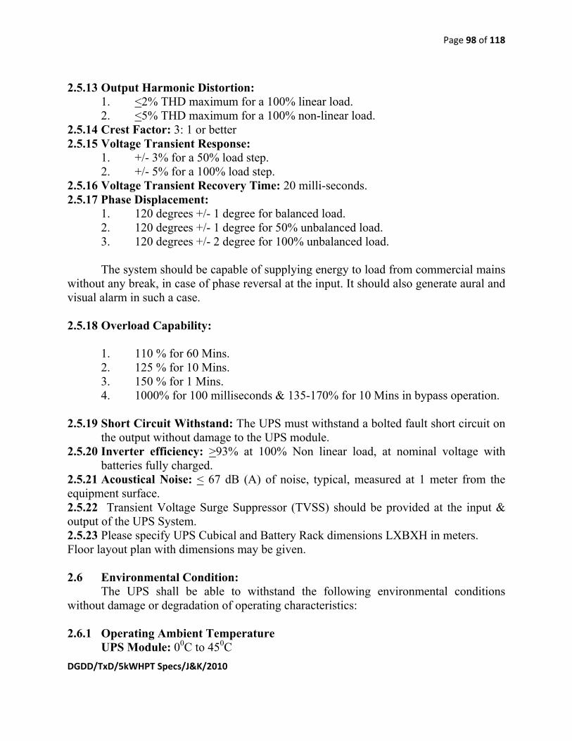
Page 98 of 118
DGDD/TxD/5kWHPT Specs/J&K/2010
2.5.13 Output Harmonic Distortion: 1. <2% THD maximum for a 100% linear load. 2. <5% THD maximum for a 100% non-linear load.
2.5.14 Crest Factor: 3: 1 or better 2.5.15 Voltage Transient Response:
1. +/- 3% for a 50% load step. 2. +/- 5% for a 100% load step.
2.5.16 Voltage Transient Recovery Time: 20 milli-seconds. 2.5.17 Phase Displacement:
1. 120 degrees +/- 1 degree for balanced load. 2. 120 degrees +/- 1 degree for 50% unbalanced load. 3. 120 degrees +/- 2 degree for 100% unbalanced load. The system should be capable of supplying energy to load from commercial mains
without any break, in case of phase reversal at the input. It should also generate aural and visual alarm in such a case.
2.5.18 Overload Capability:
1. 110 % for 60 Mins. 2. 125 % for 10 Mins. 3. 150 % for 1 Mins. 4. 1000% for 100 milliseconds & 135-170% for 10 Mins in bypass operation.
2.5.19 Short Circuit Withstand: The UPS must withstand a bolted fault short circuit on
the output without damage to the UPS module. 2.5.20 Inverter efficiency: >93% at 100% Non linear load, at nominal voltage with
batteries fully charged. 2.5.21 Acoustical Noise: < 67 dB (A) of noise, typical, measured at 1 meter from the equipment surface. 2.5.22 Transient Voltage Surge Suppressor (TVSS) should be provided at the input & output of the UPS System. 2.5.23 Please specify UPS Cubical and Battery Rack dimensions LXBXH in meters. Floor layout plan with dimensions may be given. 2.6 Environmental Condition: The UPS shall be able to withstand the following environmental conditions without damage or degradation of operating characteristics: 2.6.1 Operating Ambient Temperature UPS Module: 00C to 450C

Page 99 of 118
DGDD/TxD/5kWHPT Specs/J&K/2010
Battery: 00C to 450C 2.6.2 Storage/Transport Ambient Temperature -250C to +550C 2.6.3 Relative Humidity: <90% at 200C 2.6.4 Altitude Operating: The UPS should be able to deliver the rated output up to 3500 meters above Mean Sea Level. 2.6.5 Input Current Walk-In:
The rectifier/charger shall contain a timed walk-in circuit that causes the unit to gradually assume the load over a 5 to 30 second (User Programmable) time interval after input voltage is applied.
2.6.6 DC Filter:
The rectifier/charger shall have an output filter to minimize ripple voltage into the battery. The Ripple voltage should be less than 0.5%. The Ripple Current should be ≤5% of battery AH capacity.
2.6.7 Battery Recharge:
(a) In addition to supplying power for the inverter load, the rectifier/charger shall be capable of providing battery charging current to recharge the battery properly (up to 10% of battery AH capacity). Total Battery Management and monitoring should be available in the System. In addition to the above manual charging current control may also be provided. (b) The Battery Charger system should be able to sense source of supply as mains or Diesel Generator. In case the source of supply is Diesel Generator, it should disable battery charging and the rectifier circuit should only supply the load current. This is required to avoid overloading of the Diesel Generator as the existing 62.5 kVA Diesel Generator is sized optimally to take care of the present load of transmitter and allied equipment only and not the additional load of the ‘UPS - battery charging’. For this purpose a potential free NO/NC contact from AMF panel of DG set shall be provided by Doordarshan and this may be utilized by the UPS supplier to disable battery charging on the Diesel Generator set. The normal functioning of Battery charging should be restored immediately on switching of prime source of supply as AC mains. A line diagram of the above arrangement must be submitted with the offer.
2.6.8 Output Frequency

Page 100 of 118
DGDD/TxD/5kWHPT Specs/J&K/2010
The output frequency of the inverter shall be controlled by an oscillator. The Oscillator shall hold the inverter output frequency to +/- 0.1 Hz for steady and transient conditions. 2.6.9 Low Battery Voltage Protection: To prevent total discharge or damage to the battery, the UPS must transfer to standby operation when the battery voltage reaches a minimum voltage level (programmable). 2.6.10 Battery disconnect: An external MCCB is to be provided for protection and isolation of the battery bank from the rest of the system. 2.6.11 RF Shielding: The UPS must have RF (Radio Frequency) radiation shielding since it will be installed in strong RF field environment of 10 KW power. Any failure of electronics due to RF pick-up must be taken care of by the manufacturer. 3.0 DISPLAY AND CONTROLS:
3.1. Monitoring and Controls: The UPS shall be provided with a status display and control section designed for convenient and reliable user operation. A system power flow diagram, a percentage load and battery time remaining display shall be provided as part of the monitoring and controls sections which depict a single line diagram of the UPS. The monitoring functions such as metering, and alarms shall be displayed on a multilingual Graphic florescent backlit LCD. Language features of the monitoring system shall be in English. Minimum 100 PIECES HISTORIC EVENT RECORD should be there. 3.2 Metering
The following parameters shall be displayed: a) Input Voltage & Currents, Frequency, Power Factor b) Bypass: Phase Voltage, Line-Line Voltages, Frequency c) UPS Output: Phase Voltages, Currents, Line-Line Voltages, Power Factor, Frequency d) Local Load:
Load of Each Phase Active Power (KW), Apparent Power (KVA) of each Phase, Load Crest Factor
e) Battery: Battery Bus voltage, Battery Charge & Discharge current, Forecasted Battery Back-up Time, Battery Temperature Battery Capacity (AH) f) Parallel Load (for Parallel Operation System): Apparent Power

Page 101 of 118
DGDD/TxD/5kWHPT Specs/J&K/2010
(KVA) of Each Phase, Active Power (KW) of Each Phase 3.3. Warning, Protection and Alarm Messages:
a) Input/Mains: Charger Fault, Input Fuse Fail, Control Power 1 Fail, Mains Phase Reversed, Mains Voltage Abnormal, Mains Under-Voltage, Main Frequency Abnormal generator connected, Input Disconnect Open/closed b) Rectifier/Input Inductor/DC Bus/Booster/Balancer: Input Inductor over Temperature, rectifier Fault, rectifier over-current, Soft Start Full, Rectifier Comm. Fail, Rectifier in setting, Rectifier Over Temperature, DC Bus Abnormal, DC Bus Over-Voltage, Balancer Fault, Balancer Over-Current, Balancer Over-Temperature c) Battery: Battery Over-Temperature, Battery Fault, Battery replaced, Battery Low pre-warning, Battery end of Discharge, Battery contactor Fail, Converter Over-Current, Battery Capacity Testing, Battery Maintenance Testing, Battery Fuse Fail, Battery Contactor Open/Closed, Battery Reverse, No Battery, Battery Float Charging, Battery Boost Charging. d) Inverter: Inverter Over-Current, Inverter Asynchronous, Inverter Fault, Inverter inductor over-temperature, Inverter Over-Temperature, Inverter communication Fail, Inverter STS Fail, Inverter DC Offset, Inverter in Setting. e) Bypass: Bypass STS Fail, Bypass unable to trace, Bypass Abnormal, Maintenance Disconnect Open/Closed, Bypass disconnect open/closed, Bypass Abnormal Shutdown, Bypass Phase Reversed, Bypass over-current f) Paralleling: Parallel Board Fault, System Transfer, Parallel Communication Fail, Parallel Connect Fault g) Module’s Common: Normal Mode, Battery Mode, Bypass Mode, Ambient Over-Temperature, Fan Fault, System Overload, Manual Turn-ON/OFF, Unit overload time-out, Operation Invalid, Output Fuse Fail, Control Power 2 Fail, Unit overload, Joint Mode, UPS Shutdown, Output disabled, Transfer confirm/cancel, Unit OFF confirm, System OFF confirm, Fault Reset, Alarm Silence, Output Disconnect Open/Closed, Turn-ON Fail, Output Over-Voltage (reserved), Alarm resent, Load impact Transfer, Transfer Time-Out, Load Sharing Fault, Parallel ID Error, EPO,

Page 102 of 118
DGDD/TxD/5kWHPT Specs/J&K/2010
Setting Save Error, Mains neutral Lost, UPS System testing, protocol version Clash.
3.4 Power Status Diagram: A mimic panel shall be provided to depict a single line diagram of the UPS. Illuminating lights shall be integrated within the single line diagram to illustrate the status of the UPS. The three LEDs shall indicate the following status.
A. Bypass voltage OK B. Load on bypass C. Load on inverter
Controls: The following controls have to be accomplished with the display unit:
1. Silence an audible alarm. 2. Set the alphanumeric display language to English or the alternate language. 3. Display or program the time and date. 4. Enable or disable the automatic restart feature. 5. Transfer to or from static bypass operation. 6. Transfer to or from forced battery operation. 7. Program the unit for economy operation. 8. Program the battery charger. 9. Calculate battery back-up time. 10. Test battery condition on demand. 11. Program the unit to periodically test battery condition. 12. Program voltage and frequency windows. 13. Calibrate metered parameters. 14. Enable or disable adaptive slew rate. Set maximum slew rate. 15. Adjust set points for different alarms. 16. Program the remote shutdown contact (enable/disable remote shutdown,
polarity display). 17. Set the delay of the common fault contact. 18. Program the unit for soft start for use with a generator.
3.5 Communication Features:
RS-232 / RS485 interface ports as standard feature SNMP/HTTP Network Interface.

Page 103 of 118
DGDD/TxD/5kWHPT Specs/J&K/2010
MODEM Card. 3.6 Remote UPS Monitoring Kits: Remote UPS monitoring must be possible via either RS-232 or contact closure of the UPS.
3.7 SNMP adapter:
A Web-Enabled SNMP adapter for one or more network management systems
(NMS) to monitor and manage the UPS in TCP/IP network environments should be available. The management information base (MIB) must be provided. The SNMP interface adapter has to be connected to the UPS via the RS232 serial port. 3.8 UPS On And Off Switches:
Momentary UPS on and off Switches must be provided in a user accessible area. Upon activation of the Switches, the UPS must automatically connect the UPS output to the critical load. Upon de-activation of the Switches, the UPS must remove power from the critical load.
3.9 Integral Maintenance Bypass:
The Integral maintenance bypass has to supply the load from the bypass source while the UPS is isolated for maintenance. UPS input, output, static bypass and Maintenance Bypass Switch must be housed in the same cabinet. Each switch must be monitored and controlled by the UPS. 3.10 Battery charger temperature compensation:
For units with external batteries, the battery charger temperature compensator has to monitor the temperature in one battery cabinet.
4. ISOLATION TRANSFORMER
The isolation transformer should be three phase, naturally cooled type, housed in one steel cubical provided with unidirectional cast iron wheels at bottom and lifting hooks at the top. The cubical enclosing the isolation transformer should have doors on front and rear side, bolted side covers and removable top cover.

Page 104 of 118
DGDD/TxD/5kWHPT Specs/J&K/2010
a. AC Input: Delta 3-phase, 415 + 10% (phase to phase) b. AC Output: Star 3-phase, 415 + 10% (phase to phase)
230 (phase to neutral) c. Frequency: 47 to 53 Hz
d. Capacity: 90 KVA 3-phase (30 KVA per phase) e. Duty cycle and use Continuous, Indoor f. Common Mode Noise Rejection Better than 110 dB g. Load regulation <4% h. Insulation resistance More than 500 Mega Ohms at 500V i. Terminals Studs on fiber glass plate at rear j. Cable entry Bottom
5. EVIRONMENTAL CONDITION
1. Operating Ambient Temperature 0OC to 45OC 2. Storage/Transport Ambient -25OC to 55OC 3. Relative Humidity upto 90%.
6. Guarantee: 6.1 The supplier shall guarantee UPS and batteries for 36 months from the date of supply. Any defect/ failure of equipment/component or assembly and non-performance in this period are to be set right by the manufacturer free of costs at the premises of the consignee. A certificate from all OEMs may be attached with the offer that they will adhere to guarantee clause as above. 6.2. The UPS manufacturer shall directly employ a national field service network staffed by factory trained field service engineers to provide start up, maintenance and repair of the UPS equipment. Parts must be available through the service organization 24 hours a day, 7 days a week, 365 days a year. 6.3 The UPS manufacturer shall give the address of his local office/representative in India to facilitate interaction. In case any module of UPS requires repairs at factory, the same would be handed over to his Indian representative in India, who would arrange export of module to factory and re import in India after repairs/replacement. After sales service for maintenance and repairs in India is an essential requirement of this tender without which the offer may be rejected.

Page 105 of 118
DGDD/TxD/5kWHPT Specs/J&K/2010
Annexure I-17
1. SPECIFICATION OF DSETC OF TRANSMITTER CONTAINER/SHELTER FOR HOUSING TV TRANSMITTERS INCLUDE IND HEAT INSULATION, HEAVY DUTY BASE/ FLOORING 1.5 TON /SQM, FLOORING TILES, DOORS , WINDOW, FALSE CEILING, FINISHING, PAINTING ( COLOUR & SHADE DESIGN AS PER SITE REQUIREMENT) & INTERNAL ELECTRICAL WORKS OF LIGHT& POWER, LIGHT & POWER COPPER WIRING. VENTILATION UNITS COPPER WIRING, SWITCHES, SOCKETS, MCBS, ILLUMINATION FITTINGS, CONTAINER EXTERNAL LIGHTS & GATE LIGHTS FITTINGS, AUTOMATIC FIRE ALARM SYSTEM ETC COMPLETE AS PER SITE CONDITION
2. SPECIFICATION OF DSETC OF POWER SUPPLY CONTAINER/SHELTER FOR HOUSING POWER SUPPLY EQUIPMENT UPS , LT BOARDS, INCLUDING HEAT INSULATION, HEAVY DUTY BASE/FLOORING 1.5 TON /SQM, FLOORING TILES, DOORS , WINDOW, FALSE CEILING , FINISHING, PAINTING ( COLOUR & SHADE DESIGN AS PER SITE REQUIREMENT)& INTERNAL ELECTRICAL WORKS OF LIGHT& POWER, LIGHT & POWER COPPER WIRING, SWITCHES, SOCKETS, MCBS, ILLUMINATION FITTINGS, CONTAINER EXTERNAL LIGHTS & GATE LIGHTS FITTINGS, AUTOMATIC FIRE ALARM SYSTEM ETC COMPLETE AS PER SITE CONDITION
1. Introduction: CONTAINER/SHELTER FOR HOUSING TV TRANSMITTERS: Tender is required to work out the size as per the layout of transmitter equipment and tentative dimensions of equipment along with all Broadcasting, telecasting & O&M requirement. A detailed equipment layout plan drawing showing the Transmitter racks, Input/Monitoring/Measuring Equipment Racks, 7 ports Patch panel, Pump Rack, Combiner, dummy load, dehydrator, Power supply Equipment etc. installed in the equipment container must be attached with the offer.

Page 106 of 118
DGDD/TxD/5kWHPT Specs/J&K/2010
2. Same specification as given below is to be referred for both containers/ shelters for housing transmitter equipment & power supply equipment.
3. CONTAINER/SHELTER FOR HOUSING POWER SUPPLY EQUIPMENT: Tender is required to work out the size as per the layout of power supply equipment and tentative dimensions of equipment along with all CEA regulatory O&M requirements.
4. Scope: This specification is for design, manufacturing/fabrication, supply, transportation and installation of container/shelter to be installed at various places of Indenter in J&K Site. These shelters are meant for mobile application & should be suitable for transportation through rail, road & air . These are used in the field under severe weather & physical condition. A drawing specific to each shelters / shelter should be submitted by the tenderer.
5. Information to be supplied with the tender:
a) A Compliance Statement to the complete specification of indenter, para wise, for each clause. b) Complete printed technical literature/data sheet/ detailed information
including technical manual (if any) of Container/shelter from the Original Equipment Manufacturer (OEM) in support of compliance statement should be furnished for all the items of the tender, to assess the full merit of the offer, without which the tender will be considered incomplete and is liable for rejection
c) Descriptive information giving complete details of container/shelter offered. d) Detailed Schedule of Requirement/Materials offered for SETC of the
container/shelter should be in conformity with Part 4.0 without any change in format without price (un-priced) failing which the tender shall be considered incomplete and will be liable for rejection. The tenderer must quote all items.
e) Country of origin, make, type, model number in respect of all items should be submitted along with the name & address of their vendors.
f) Layout and construction details of container/shelter including dimensions, weights, overall sizes and photographs of the interior of the container/shelter. This should include tentative accommodation plan with Plan, front elevation, back elevation , side view for each container/shelter separately, failing which the tender shall be considered incomplete and will be liable for rejection..
g) Complete drawings with a sections, structural details with list of all hardware material as per IS amended up to date of container/shelter separately as per specification are to be submitted with the offer.

Page 107 of 118
DGDD/TxD/5kWHPT Specs/J&K/2010
6. Guarantee : The cabin will be guaranteed and a general undertaking to accept the guarantee will be furnished by the tenderer that:
1. the shelter supplied will be in accordance with these specifications, varied only to the extent stated in tender’s offer and agreed to in the contract.
2. to make good within 30 days at tenderer expense any component which becomes defective under normal operating conditions during 18 months from the date of acceptance of the equipment at respective site or 12 months from the date of commissioning at site whichever is earlier.
7 REQUIREMENTS
7.1 Operating and environmental conditions
The shelter should withstand, without damage, the following environmental conditions and remain fit for its intended use after being exposed to such condition. Some of the stresses may be simultaneous.
7.1.1 Temperature : -10°c to 50°c
7.1.2 Wind speed: Operational : 70 Km per hour
Wind speed : Survival : 150 Km per hour
or as per IS/CPWD specification which ever is higher
7.1.3 Sealing: During storage, transit and operation, the shelter should be rainproof (with the opening fitted with. Shutters as applicable). All exposed seals and edges should be assembled so as not to absorb nor retain humidity.

Page 108 of 118
DGDD/TxD/5kWHPT Specs/J&K/2010
7.1.4 Electric field : The screening should be sufficiently effective to provide a 60 dB minimum electric field attenuation, in the frequency range of 1500 KHz to 1000 MHz.
7.1.5 Atmospheric: It should be able to with stand as site condition.
7.2 Panel construction
The shelter shall be fully enclosed and thermally insulted. All Panels should essentially be free from corrosion, dents scratches and gouges. The facing should preferably made of sheets without joints. These should be flat aluminum alloy sheets, free from corrosion, dents, scratches and other similar defects. The aluminum sheets should not be affected by natural causes like humidity, rain, atmospheric heat and dust.
Design of shelter/ container should be withstand the wind speed 198 km/hr.
7.3 Other features
All the joints should provide sealing against ingress of moisture in to the panel and the interior of the shelters. Each shelter should be provided with a main entrance door and an emergency hatch on main door . The door should be made of same material as that of the wall panel. All doors should be with round corner. The electrical continuity between the cabin doors and panel should be ensured by providing RF shielded gasket. The electrical continuity with door open should be ensured by earthling braid. One safety lock with three key should be supplied with main door, the emergency hatch should be operable from inside by means of special accessory clipped on to the hatch door.
The door locking bar should be possible to the operated by handles provided on both inside and outside handles. The hinge fixing should be done in such that the rigid skids can be replaced by flexible skids when application from outside. The shelter should be provided with skids which are screwed on to the bottom on the shelter. The pitch of the fixing screws should be such that the rigid skids can be replaced by flexible skids when application so warrants. The internal and external metallic skin of the panels should be electrically continuous independently and electrically separated from each other except at one point where they are connected together and grounded resulting in double electrically isolated construction.

Page 109 of 118
DGDD/TxD/5kWHPT Specs/J&K/2010
8 CONSTRUCTION REQUIREMENTS:
8.1 Metal and mechanical Assemblies
Mechanical assemblies should be designed and protected against electrolytic corrosion. Metal parts should bear no marks of corrosion, blisters, chips or scratches.
8.2 Nuts and Bolts
The nuts and bolts used should meet the requirements of the ISI standards. Nuts and bolts used should be Either stainless steel or steel hot dip galvanized .
8.3 Insulating Materials
The insulating material should be suitable for thermal /heat insulation as per site condition.
8.4 The dimensional details, features and special load bearing requirements should be capable to bear the load of 2 Nos. of 5 kW UHF TV Transmitters and their auxiliary equipment setup with the safety factor of 1.5. 9: Structure and material:
9.1 Material: All the material used in the construction of the container/shelter will be ISI marked and as per approved structural drawings of the structural design agency/ Institute as mention in Para 5.2. The material in totality required shall be designed as per site terrain , loading requirement including the factor of safety better than 2 (two) under the worst conditions
9.2 Safety and structural design: The strength of the structure of container/shelter base support, sides wall panels, roof , flooring etc shall be able to withstand wind velocity as mentioned in clause 3.0 as above or as per CPWD/IS specifications as applicable at the site or which ever is higher. Structural design of container/shelter under worst atmospheric conditions and terrain shall be better than 2(two) and shall be got approved from IIT/SERC by the tenderer.

Page 110 of 118
DGDD/TxD/5kWHPT Specs/J&K/2010
10 General:
(i) Civil heavy duty flooring
(ii) Heat Insulation
(iii) Flooring tiles
(iv) Doors, windows, false ceiling
(vi) Finishing, painting (design and shade as per site requirement)
like entrance sliding steel door from out side and sliding aluminum gate from inside, Double glass airtight windows of anodized aluminium with aluminum grill along with glass, handle lock, U-channel etc.
11 Electrical work:
11.1 Electrical fittings and other accessories etc. : The quantities of items may vary as per actual site requirement.
(i) Recessed type twin fluorescent 4´×40 W, mirror optic decorative fitting
(ii) Container outside lights/Gate lights
(iii) MCBs for Light & power installation
(iv) SP&N, MCBs with industrial socket and metal box with steel frames
(v) Light points, power points, light sockets etc.
(vi) Automatic fire alarm system.
11.2 Electrical Switch gear etc. along with protection short circuit, over load & earth fault. Rates for above items will be quoted separately item wise by the tenderer.

Page 111 of 118
DGDD/TxD/5kWHPT Specs/J&K/2010
11.3 Electrical Wiring: Light Points wiring, power point wiring ,circuit wiring, submain wiring and wiring for Ventilation equipment shall be carried out with copper wiring stranded conductor as per IS/ CPWD specification amended uptodate.
12 Working and life:
The workmanship of the proposed container structure will have a very good finish and should reflect the skilled workmanship. The life of the structure shall not be less than 50 years. The various tools and miscellaneous items required for the installation of container will be arranged by the tenderer himself. Painting on wall panels, windows etc. of the container will be done by the tenderer with two coats of paint. Paint will be ISI marked. Colour of paint will be decided by zonal office.
13 Inspection of site: The container as per the suggestive specification will be constructed by the firm at site. Transportation and other charges for the installation of the container etc. at site are the part of the tender and no extra payment shall be made on this account. (A) Electrical Installation points details of transmitter container S.NO. DESCRIPTION QUANTITY^^
1. 5 Amp light point 8 nos,2x40 watt
8 nos
2. 5 Amp plug point 4 nos x100 watt
4
3. Cabin floodlight points/ gate light
5 nos x 100 watt
5
4. 20 Amp MCB with Industrial Socket including Metal box frame complete for ventilating units.
5

Page 112 of 118
DGDD/TxD/5kWHPT Specs/J&K/2010
(B)Electrical Installation points details of power supply container
S.NO. DESCRIPTION QUANTITY^^
1. 5 Amp light point 6 nos,2x40 watt
6 nos
2. 5 Amp plug point 4 nos x100 watt
4
3. Cabin floodlight points/gate light
5 nos x 100 watt
5
4. 20 Amp MCB with Industrial Socket including Metal box frame complete for Heaters
5
^^ Quantity may vary as per size on container.

Page 113 of 118
DGDD/TxD/5kWHPT Specs/J&K/2010
Annexure I-18 Specifications for Audio Analyzer 1. SCOPE: The Audio Analyzer should be a precision instrument, suitable for making direct Audio measurements of a "T.V. Transmitter system". It should be capable to monitor all the Audio parameters of a Analog TV Transmitter system. It should also have the up gradation facility for measuring digital parameters. 2. Features and Measurements required: 2.1 Analog Audio measurement functions: Instrument must have the facility to measure the following Analog audio parameters of an Analog TV Transmitter- (i) Level (ii) Cross talk (iii) Frequency (iv) Total Harmonic distortion (v) Noise (vi) Wow and Flutter (vii) Drift (viii) Inter modulation Distortion (ix) Narrow band selective level (x) Spectral FFT analysis 2.2 Digital Audio measurement functions: Instrument must have the up gradation facility to measure the following Digital audio parameters of a Digital TV Transmitter (DVB-T2 Standard): (i) Carrier Level (ii) Sampling Frequency (iii) Jitter Analysis (iv) Peak level (v) Bit statistics (vi) Status Analysis 3.0 Technical Specifications:-
SL. NO.
Parameters Values
1. Standard PAL B/G colour standard for Analog and DVB-T2 for

Page 114 of 118
DGDD/TxD/5kWHPT Specs/J&K/2010
Digital 2.0 General Data 2.1 Operating Temperature
Range 0 to 45ºC
2.2 Humidity 10% to 90% (Non conditioning) 2.3 Power Supply 230V ± 10% 3.0 Audio Inputs/Outputs 3.1 Connectors BNC, two channels simultaneously operating. 3.2 Frequency Range 10 Hz to 80 KHz. 3.3 Frequency response from
20 Hz to 20 KHz. (Referenced to 1 KHz)
±0.05dB
3.4 Common Mode Rejection at 1 KHz
≥ 75 dB
3.5 Harmonic Distortion (a) Fundamental
Range (b)
20 Hz to 20 KHz
3.6 Maximum Input Voltage 33 Volt rms

Page 115 of 118
DGDD/TxD/5kWHPT Specs/J&K/2010
Annexure I-19 I. SPECIFICATION OF AMPLISPEAKER
The system should be high grade transducer of professional audio monitoring quality. Unit must have an ON/OFF switch with LED indication and a level control. Transducer components like Woofer and Tweeter must be magnetically shielded. Technical Specifications-
Sr. No. Description Parameters 1. Power Supply 230VAC±10%, 50Hz. 2. Amplifier power without clipping LF-45W, HF-45W 3. S/N ratio >90dB 4. Gain control range ±6dB 5. Volume control range >70dB 6. CMRR >65dB 7. Protection Over current, Over
heat, RFI, Switch On/Off transients.
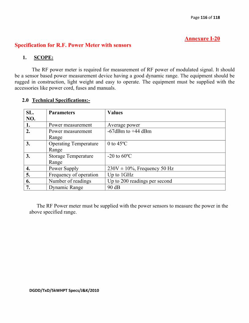
Page 116 of 118
DGDD/TxD/5kWHPT Specs/J&K/2010
Annexure I-20 Specification for R.F. Power Meter with sensors
1. SCOPE:
The RF power meter is required for measurement of RF power of modulated signal. It should be a sensor based power measurement device having a good dynamic range. The equipment should be rugged in construction, light weight and easy to operate. The equipment must be supplied with the accessories like power cord, fuses and manuals.
2.0 Technical Specifications:-
SL. NO.
Parameters Values
1. Power measurement Average power 2. Power measurement
Range -67dBm to +44 dBm
3. Operating Temperature Range
0 to 45ºC
3. Storage Temperature Range
-20 to 60ºC
4. Power Supply 230V ± 10%, Frequency 50 Hz 5. Frequency of operation Up to 1GHz 6. Number of readings Up to 200 readings per second 7. Dynamic Range 90 dB
The RF Power meter must be supplied with the power sensors to measure the power in the above specified range.

Page 1 of 118
DGDD/TxD/5kWHPT Specs/J&K/2010
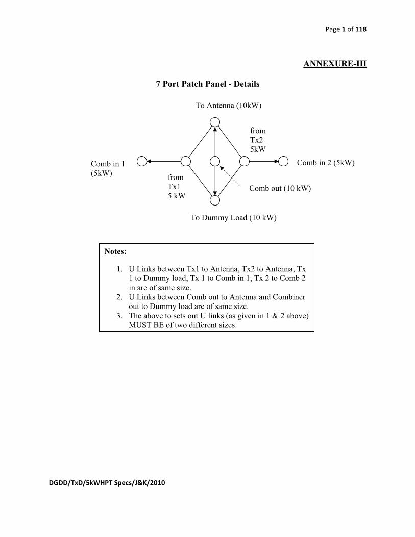
Page 1 of 118
DGDD/TxD/5kWHPT Specs/J&K/2010
ANNEXURE-III
7 Port Patch Panel - Details
Notes:
1. U Links between Tx1 to Antenna, Tx2 to Antenna, Tx 1 to Dummy load, Tx 1 to Comb in 1, Tx 2 to Comb 2 in are of same size.
2. U Links between Comb out to Antenna and Combiner out to Dummy load are of same size.
3. The above to sets out U links (as given in 1 & 2 above) MUST BE of two different sizes.
fromTx1 5 kW
from Tx2 5kW
Comb in 2 (5kW)Comb in 1 (5kW)
To Antenna (10kW)
To Dummy Load (10 kW)
Comb out (10 kW)