pfaff 1183 instruction manual - szwalnicze
TRANSCRIPT

INSTRUCTION MANUAL
296-12-18 610/002Betriebsanleitung engl. 06.09
This instruction manual applies to machines from the following serial numbers onwards:# 6 001 000
1183-712/02
Industrial
®

This Instruction Manual is valid for all models and subclasses listed in the chapter "Specifications ".
The adjustment manual for the machines can be downloaded free of charge from the internet address
www.pfaff-industrial.com/pfaff/de/service/downloads As an alternative to the internet download the adjustment manual can also be ordered in book form under part no. 296-12-18 611/002.
The reprinting, copying or translation of PFAFF Instruction Manuals, whether in whole or in part, is only permitted with our previous authorization and with written reference to the source.
PFAFF Industriesysteme und Maschinen AG
Hans-Geiger-Str. 12 - IG Nord
D-67661 Kaiserslautern

Index
Contents ................................................................................. Chapter - Page
1 Safety ........................................................................................................................... 1 - 1
1.01 Directives ...................................................................................................................... 1 - 11.02 General notes on safety ................................................................................................ 1 - 11.03 Safety symbols ............................................................................................................. 1 - 21.04 Important points for the user ........................................................................................ 1 - 21.05 Operating and specialist personnel ............................................................................... 1 - 31.05.01 Operating personnel ...................................................................................................... 1 - 31.05.02 Specialist personnel ...................................................................................................... 1 - 31.06 Danger .......................................................................................................................... 1 - 4
2 Proper use.................................................................................................................... 2 - 1
3 Specifications .............................................................................................................. 3 - 1
3.01 PFAFF 1183-712/02 ....................................................................................................... 3 - 13.02 Models and subclasses ................................................................................................. 3 - 1
4 Disposal of machine ................................................................................................... 4 - 1
5 Transport, packaging and storage ............................................................................. 5 - 1
5.01 Transportation to customer's premises ........................................................................ 5 - 15.02 Transport within the customer’s premises ................................................................... 5 - 15.03 Disposal of the packaging ............................................................................................. 5 - 15.04 Storage ......................................................................................................................... 5 - 1
6 Explanation of the symbols ........................................................................................ 6 - 1
7 Controls ....................................................................................................................... 7 - 1
7.01 On/off switch ................................................................................................................ 7 - 17.02 Pedal ............................................................................................................................. 7 - 17.03 Control panel ................................................................................................................. 7 - 27.03.01 Screen displays ............................................................................................................. 7 - 27.03.02 Function keys ................................................................................................................ 7 - 2
8 Mounting and commissioning the machine ............................................................. 8 - 1
8.01 Mounting ....................................................................................................................... 8 - 18.01.01 Adjusting the table-top height ....................................................................................... 8 - 18.01.02 Garnrollenständer montieren......................................................................................... 8 - 28.02 Connecting the plug-in connections and earth cables ................................................... 8 - 38.03 Start inhibitor ................................................................................................................. 8 - 48.03.01 Mounting the start inhibitor ........................................................................................... 8 - 48.03.02 Checking the start inhibitor function ............................................................................. 8 - 48.04 Basic setting of the machine drive unit ......................................................................... 8 - 58.05 Commissioning ............................................................................................................. 8 - 78.06 Switching the machine on/off ....................................................................................... 8 - 78.07 Table top cutout ............................................................................................................ 8 - 88.08 Mounting the table top .................................................................................................. 8 - 9
Index
Contents ................................................................................. Chapter - Page
9 Preparation .................................................................................................................. 9 - 1
9.01 Inserting the needle ...................................................................................................... 9 - 19.02 Winding the bobbin thread, adjusting the thread tension .............................................. 9 - 29.03 Removing/Inserting the bobbin case ............................................................................. 9 - 39.04 Inserting the bobbin case / Adjusting the bobbin thread tension ................................... 9 - 39.05 Threading the needle thread / Adjusting the needle thread tension .............................. 9 - 4
10 Care and maintenance .............................................................................................. 10 - 1
10.01 Cleaning the machine .................................................................................................. 10 - 110.02 Topping up the oil tank ................................................................................................ 10 - 2
11 Wearing parts ............................................................................................................ 11 - 1

Safety
1 - 1
1 Safety
1.01 Directives
This machine is constructed in accordance with the European regulations contained in theconformity and manufacturer’s declarations.In addition to this Instruction Manual, also observe all generally accepted, statutory and otherregulations and legal requirements and all valid environmental protection regulations!The regionally valid regulations of the social insurance society for occupational accidents orother supervisory organizations are to be strictly adhered to!
1.02 General notes on safety
● This machine may only be operated by adequately trained operators and only after havingcompletely read and understood the Instruction Manual!
● All Notes on Safety and Instruction Manuals of the motor manufacturer are to be readbefore operating the machine!
● The danger and safety instructions on the machine itself are to be followed!
● This machine may only be used for the purpose for which it is intended and may not beoperated without its safety devices. All safety regulations relevant to its operation are tobe adhered to.
● When exchanging sewing tools (e.g. needle, roller presser, needle plate and bobbin),when threading the machine, when leaving the machine unattended and duringmaintenance work, the machine is to be separated from the power supply by switchingoff the On/Off switch or by removing the plug from the mains!
● Everyday maintenance work is only to be carried out by appropriately trained personnel!
● Repairs and special maintenance work may only be carried out by qualified service staffor appropriately trained personnel!
● Work on electrical equipment may only be carried out by appropriately trained personnel!
● Work is not permitted on parts and equipment which are connected to the power supply!The only exceptions to this rule are found in the regulations EN 50110.
● Modifications and alterations to the machine may only be carried out under observance ofall the relevant safety regulations!
● Only spare parts which have been approved by us are to be used for repairs! Weexpressly point out that any replacement parts or accessories which are not supplied byus have not been tested and approved by us. The installation and/or use of any suchproducts can lead to negative changes in the structural characteristics of the machine.We are not liable for any damage which may be caused by non-original parts.

Safety
1 - 2
1.03 Safety symbols
Danger!Points to be observed.
Danger of injury for operating and specialist personnel!
CautionDo not operate without finger guard and safety devices.Before threading, changing bobbin and needle, cleaningetc. switch off main switch.
I
1.04 Important points for the user
● This Instruction Manual is an integral part of the machine and must be available to theoperating personnel at all times.
● The Instruction Manual must be read before operating the machine for the first time.
● The operating and specialist personnel is to be instructed as to the safety equipment ofthe machine and regarding safe work methods.
● It is the duty of the user to only operate the machine in perfect running order.
● It is the obligation of the user to ensure that none of the safety mechanisms are removedor deactivated.
● It is the obligation of the user to ensure that only authorized persons operate and work onthe machine.
Further information can be obtained from your PFAFF agent.
Safety
1 - 3
1.05 Operating and specialist personnel
1.05.01 Operating personnel
Operating personnel are persons responsible for the equipping, operating and cleaning of themachine as well as for taking care of problems arising in the sewing area.
The operating personnel is required to observe the following points and must:
● always observe the Notes on Safety in the Instruction Manual!
● never use any working methods which could adversely affect the safety of the machine!
● not wear loose-fitting clothing or jewelery such as chains or rings!
● also ensure that only authorized persons have access to the potentially dangerous areaaround the machine!
● always immediately report to the person responsible any changes in the machine whichmay limit its safety!
1.05.02 Specialist personnel
Specialist personnel are persons with a specialist education in the fields of electrics,electronics and mechanics. They are responsible for the lubrication, maintenance, repair andadjustment of the machine.The specialist personnel is obliged to observe the following points and must:
● always observe the Notes on Safety in the Instruction Manual!
● switch off the On/Off switch before carrying out adjustments or repairs, and ensure thatit cannot be switched on again unintentionally!
● wait until the luminous diode on the control box is no longer blinking or on beforebeginning adjustment or repair work.
● never work on parts which are still connected to the power supply! Exceptions areexplained in the regulations EN 50110.
● replace the protective coverings and close the electrical control box afer all repairs ormaintenance work!
Safety
1 - 4
96-001
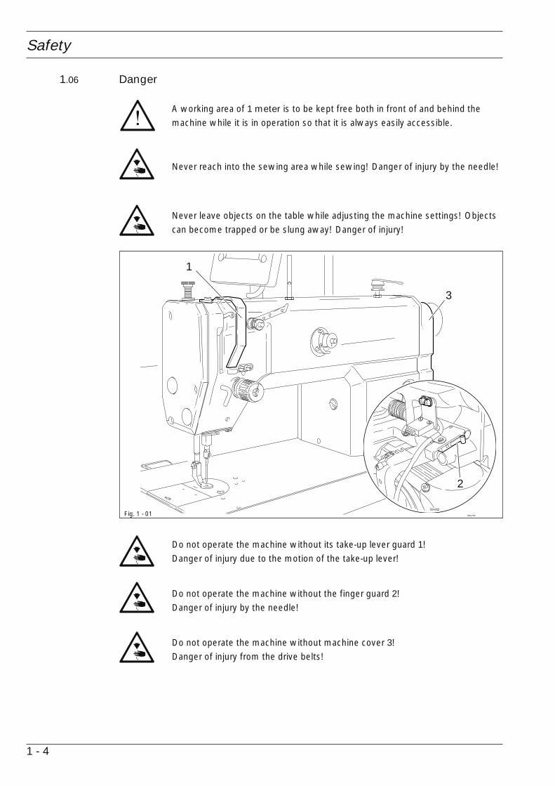
Do not operate the machine without its take-up lever guard 1!Danger of injury due to the motion of the take-up lever!
Do not operate the machine without the finger guard 2!Danger of injury by the needle!
Do not operate the machine without machine cover 3!Danger of injury from the drive belts!
1.06 Danger
A working area of 1 meter is to be kept free both in front of and behind themachine while it is in operation so that it is always easily accessible.
Never reach into the sewing area while sewing! Danger of injury by the needle!
Never leave objects on the table while adjusting the machine settings! Objectscan become trapped or be slung away! Danger of injury!
Fig. 1 - 01
3
1
93-002
2

Proper use
2 - 1
2 Proper use
The PFAFF 1183-712/02 is a single-needle, lockstitch, flatbed sewing machine for industrialtacking and basting work.
Any and all uses of this machine which have not been approved of by themanufacturer are considered to be inappropriate! The manufacturer cannot beheld liable for any damage caused by the inappropriate use of the machine! Theappropriate use of the machine includes the observance of all operational,adjustment, maintenance and repair measures required by the manufacturer!

Specifications
3 - 1
3 Specifications
3.01 PFAFF 1183-712/02▲
Stitch type: .................................................................................................. 301 (lockstitch)Needle system: .......................................................................................................134 - 35
Needle size in 1/100 mm:........................................................................................80 - 100
Presser foot clearance: ............................................................................................ 16 mmClearance width: .................................................................................................... 260 mmClearance height: ................................................................................................... 125 mm
Bedplate dimensions: ................................................................................... 476 x 177 mm
Sewing head dimensions:Length: ..............................................................................................................ca. 550 mmWidth: ...............................................................................................................ca. 180 mmHeight (above table): .........................................................................................ca. 300 mm
Max. speed: ...................................................................................................... 1200 spm ◆
Needle bar stroke: .................................................................................................... 36 mm
Connection data:Operating voltage: ..........................................................................230 V ± 10 %, 50/60 HzMax. power consumption: ....................................................................................... 400 VAFuse protection: ............................................................................................ 1 x 16 A, inert
Noise data:Noise emission level at workplace with a sewing speed of 1000 spm: ... LpA ≤ 68,5 dB(A) ■
(Noise measurement in accordance with DIN 45 635-48-A-1, ISO 11204, ISO 3744, ISO4871)
Net weight of sewing head: .................................................................................. ca. 30 kgGross weight of sewing head: .............................................................................. ca. 38 kg
■ KpA = 2,5 dB
▲ Subject to alterations◆ Depending on the material and sewing operation
3.02 Models and subclasses
Additional equipment:
Subclass -900/24 ............................................................................ Thread trimming device
Disposal of machine
4 - 1
4 Disposal of machine
● The proper disposal of the machine is the responsibility of the customer.
● The materials used in the machines are steel, aluminium, brass and various plastics.The electrical equipment consists of plastics and copper.
● The machine is to be disposed of in accordance with the locally valid environmentalprotection regulations. If necessary, a specialist is to be commissioned.
Special care is to be taken that parts soiled with lubricants are separatelydisposed of in accordance with the locally valid pollution control regulations!

Transport, packaging and storage
5 - 1
5 Transport, packaging and storage
5.01 Transportation to customer's premises
The machines are delivered completely packed.
5.02 Transport within the customer’s premises
The manufacturer bears no liability for transport within the customer’s premises or to the in-dividual locations of use. Make sure that the machines are always transported upright.
5.03 Disposal of the packaging
The packaging of these machines consists of paper, cardboard and VCE fiber. The properdisposal of the packaging is the responsibility of the customer.
5.04 Storage
The machine can be stored for up to 6 months if not in use. During this time it should beprotected from dust and moisture.For longer storage the individual parts of the machine, especially the moving parts, must beprotected from corrosion, e.g. by a film of oil.

Explanation of the symbols
6 - 1
6 Explanation of the symbols
In the following section of this Instruction Manual, certain tasks or important pieces ofinformation are accentuated by symbols.The symbols used have the following meanings:
Note, information
Cleaning, care
Lubrication, greasing
Servicing, repairing, adjustment, maintenance(only to be carried out by specialist personnel)

Controls
7 - 1
96-0
03
7 Controls
7.01 On/off switch
● Switch the machine on or off by turningon/off switch 1.
Fig. 7 - 01
01
7.02 Pedal
0 = Neutral position
1 = Sewing
2 = Cut thread (on machineswith –900/24)
Fig. 7 - 02
0
1
2

Controls
7 - 2
7.03 Control panel
The control panel consists of display 1 and the function keys described below. The display 1consists of a single-line alpha-numerical, 7 segment LCD display with 8 symbols. The texts2, located above and next to the LCD display, show the respective status of the functionkeys and the operating status of the machine. The control panels switches on all LCD-segments and the horn automatically for a short time during the power-on phase, afterwhich the lettering PFAFF appears on the display, until the higher-ranking control unit sendscommands to the control panel.The function keys are located around the display 1. They are foil-packed without permanentmarking and without contact signal. Fixed functions are allocated to the keys, see Chapter
7.03.02 Function keys.
7.03.01 Screen displays
● Activated functions are displayed with a triangular marking 3 below or next to therespective function key.
● During the parameter input the selected parameter number with the corresponding valueis displayed, see Chapter 12.07.02 Example of a parameter input.
7.03.02 Function keys
The function keys described below are used basically to switch machine functions on andoff.Each time a key is pressed, this must be confirmed by at least one beep tone. Irrespectiveof the machine mode a double beep signal is given if invalid keys are pressed or maximumvalues reached.If a corresponding value has to be set for the activated function, this is carried out with thecorresponding +/- key. By pressing and holding the corresponding +/- key, the relevantnumerical value 4 is changed slowly to begin with. If the corresponding +/- key is held downlonger, the values change more quickly.
A B C D
3 3 3 3
12 3
SPEED TE ERROR
4

Controls
7 - 3
Start backtack
● This function key is not used on this machine.
End backtack
● This function key is not used on this machine.
Needle position
● If this key is pressed the "needle raised after sewing stop" function is switched on or off.When the function is switched on, the needle positions at t.d.c. after sewing stops.
Foot position after stop
● This function key is not used on this machine.
Foot position after trimming
● This function key is not used on this machine.
Thread trimmer
● If this key is pressed the thread trimming function is switched on or off.
Darning program
● This function key is not used on this machine.
Counted seam● This function key is not used on this machine.
TE/Speed
● If this key is pressed once the speed limit for the sewing mode is activated.● If this key is pressed twice (within 5 seconds) the machine changes from sewing to input
mode.

8 - 1
Mounting and commissioning the machine
8 Mounting and commissioning the machine
The machine must only be mounted and commissioned by qualified personnel!All relevant safety regulations are to be observed!
If the machine is delivered without a table, be sure that the frame and the tabletop which you intend to use can hold the weight of the machine and the motor.It must be ensured that the supporting structure is sufficiently sturdy, evenduring sewing operations.
8.01 Mounting
The necessary electricity supply must be available at the machine’s location. Also, a stableand horizontal surface as well as adequate lighting are required at the location.
Depending on the type of table, the method of packaging used may require thatthe table top be lowered for transport. The following is a description of how toadjust the height of the table top.
8.01.01 Adjusting the table-top height
● Loosen screws 1 and 2 and set the desired table-top height● Tighten screws 1 well.● Adjust the pedal to the desired position and tighten screw 2.
Fig. 8 - 01
1
2
1

8 - 2
Mounting and commissioning the machine
8.01.02 Garnrollenständer montieren
● Garnrollenständer gemäß Fig. 8-02 mon-tieren.
● Anschließend den Ständer in dieBohrung der Tischplatte einsetzen undmit den beiliegenden Muttern befestigen.
Fig. 8 - 02

8 - 3
Mounting and commissioning the machine
90-0
04
8.02 Connecting the plug-in connections and earth cables
Fig. 8 - 03
● Connect all plugs as labelled to the control box 1.● Screw the earth cable from the sewing head and the main switch to earth point A.● Connect earth point A to earth point B with earth cable 2.● Screw the earth cable 3 from the motor to earth point B.
A3
1
2
B

8 - 4
Mounting and commissioning the machine
8.03 Start inhibitor
8.03.01 Mounting the start inhibitor
Fig. 8 - 04
● Set the machine into the table top.● After loosening screws 2, set switch 1 so
that it is activated when the sewing headis in an upright position.
● In this position tighten screws 2.
1
2
8.03.02 Checking the start inhibitor function
● Switch the machine on at the main switch and tilt back the sewing head.The error message "E9" must appear on the control panel.
● If the message does not appear, check the setting of safety switch 1.
● Set the sewing head upright and acknowledge the error message by pressing theTE/Speed key. The machine is ready for operation again.
E 9ERROR

8 - 5
Mounting and commissioning the machine
8.04 Basic setting of the machine drive unit
● Switch on the machine.
● Press TE/Speed key twice to call up the input mode.2 x
● By pressing the corresponding +/- key, call up parameter "798" and select service level"C", see Chapter 12.07.01 Selecting the user level.
● By pressing the corresponding +/- key, call up parameter "800" (rotation direction of themotor).
● By pressing the corresponding +/- key, set the value at "1".
TE
101 on
A B C D
3 3 3 3
TE
798 11C
A
● By pressing the corresponding +/- key, call up parameter "700".
TE
800 1C

8 - 6
Mounting and commissioning the machine
TE
700 5C
● By operating the pedal, sew one stitch.
● Turn the balance wheel in the direction of sewing until the tip of the needle is level withthe top edge of the needle plate.
● By pressing the corresponding +/- key, call up parameter "702".
● By pressing the corresponding +/- key, enter the value "80".
● Conclude the adjustment of the sewing motor by pressing the TE/Speed key.
TE
702 80C
● By pressing the corresponding +/- key, call up parameter "703".
● By pressing the corresponding +/- key, enter the value "226".
TE
703 226C
8 - 7
Mounting and commissioning the machine
8.06 Switching the machine on/off
● Switch the machine on (see Chapter 7.01 Main switch).
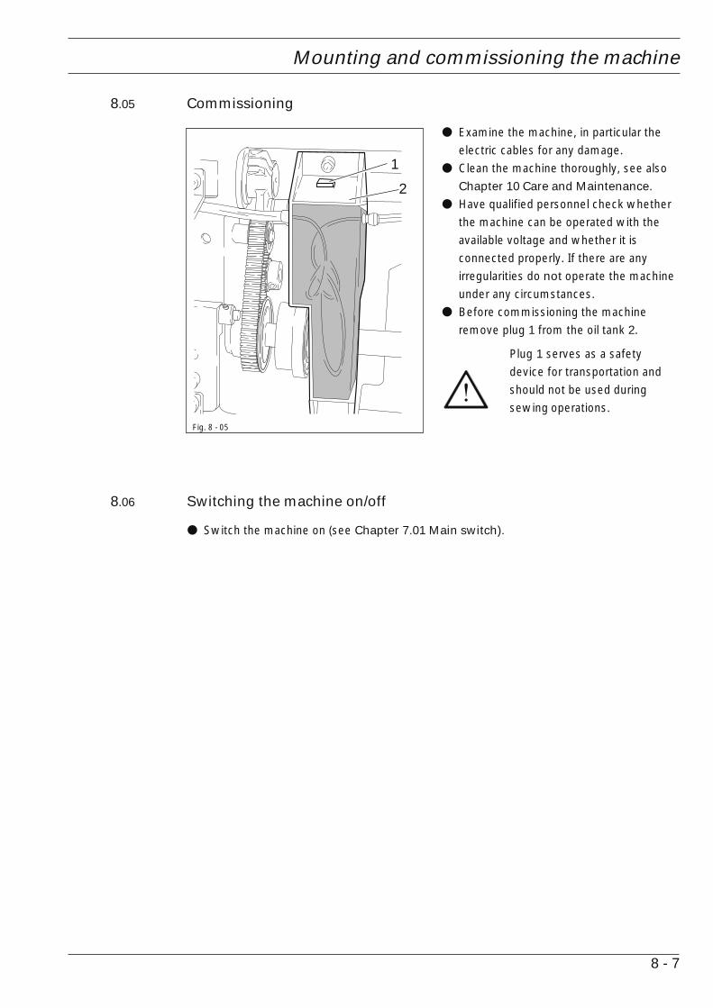
8.05 Commissioning
● Examine the machine, in particular theelectric cables for any damage.
● Clean the machine thoroughly, see alsoChapter 10 Care and Maintenance.
● Have qualified personnel check whetherthe machine can be operated with theavailable voltage and whether it isconnected properly. If there are anyirregularities do not operate the machineunder any circumstances.
● Before commissioning the machineremove plug 1 from the oil tank 2.
Plug 1 serves as a safetydevice for transportation andshould not be used duringsewing operations.
Fig. 8 - 05
1
2

8 - 8
Mounting and commissioning the machine
8.07 Table top cutout

8 - 9
Mounting and commissioning the machine
Ans
icht
:Ti
schp
latte
nunt
erse
ite
Sta
nd p
ositi
on90
6-35
50-0
05/8
95
50
170
8.08 Mounting the table top
Con
trol
box
View
:U
nder
side
tab
le t
op
Spe
edco
ntro
luni
t

Preparation
9 - 1
9 Preparation
All regulations and instructions in this Instruction Manual are to be observed!Special attention is to be paid to the safety regulations!
All preparation work is only to be carried out by appropriately trained personnel.Before all preparation work, the machine is to be separated from the electricitysupply by removing the plug from the mains or switching off the On/Off switch!
9.01 Inserting the needle
Switch off the machine!Danger of injury due tounintentional starting of themachine!
Only use needles from thesystem intended for themachine, see Chapter 3
Specifications.
● Raise needle bar.● Loosen screw 1 and insert needle 3 until
you feel it stop.● The long needle groove must be aligned
in the direction of the machine head.● Tighten screw 1.
Fig. 9 - 01
1
2

Preparation
9 - 2
● Place an empty bobbin 1 onto bobbin shaft 2.● Thread the bobbin in accordance with Fig. 9-02 and wind it anti-clockwise around bobbin
1 a few times.● Switch on the bobbin winder while at the same time pressing bobbin winder spindle 2
and lever 3.
The bobbin fills up during sewing.
If the machine is only used for winding the bobbin (without sewing), a bobbincase must be set into the hook! Danger of damage to the hook!
● The tension of the thread on bobbin 1 can be adjusted with knurled screw 4.● The bobbin winder stops automatically when bobbin 1 is full.
If the thread is wound unevenly:● Loosen nut 5.● Turn thread guide 6 accordingly.● Tighten nut 5.
Fig. 9 - 02
6
5
4
9.02 Winding the bobbin thread, adjusting the thread tension
-
3
2
1
+

Preparation
9 - 3
9.03 Removing/Inserting the bobbin case
Switch off the machine!Danger of injury due tounintentional starting of themachine!
Removing the bobbin case:
● Tilt back the machine.● Raise latch 1 and remove bobbin case 2.
Inserting the bobbin case:
● Press bobbin case 2 until you feel it snapinto the bobbin case base.
Return the machine to itsupright position using both
hands!Danger of injury by crushingbetween the machine and thetable top!Fig. 9 - 03
9.04 Inserting the bobbin case / Adjusting the bobbin thread tension
● Insert the bobbin into the bobbin case.● Pass the thread through the slot under
the spring according to Fig. 9-04.
● Pass the thread through the notch.● Adjust the thread tension by turning
screw 1.
When the thread is pulled, thebobbin must rotate in thedirection of the arrow.
Fig. 9 - 04
5 cm
1+
-
2
1

Preparation
9 - 4
96-0
08
1
-+
9.05 Threading the needle thread / Adjusting the needle thread tension
Fig. 9 - 05
Switch off the machine!Danger of injury due to unintentional starting of the machine!
● Thread the machine as shown in Fig. 9-05.● Adjust the needle thread tension by turning disk 1.
Care and maintenance
10 - 1
96-0
09
10 Care and maintenance
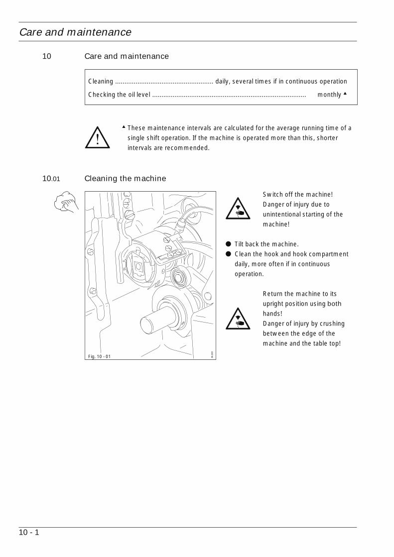
Cleaning ..................................................... daily, several times if in continuous operation
Checking the oil level ................................................................................... monthly ▲
▲ These maintenance intervals are calculated for the average running time of asingle shift operation. If the machine is operated more than this, shorterintervals are recommended.
10.01 Cleaning the machine
Switch off the machine!Danger of injury due tounintentional starting of themachine!
● Tilt back the machine.● Clean the hook and hook compartment
daily, more often if in continuousoperation.
Return the machine to itsupright position using both
hands!Danger of injury by crushingbetween the edge of themachine and the table top!
Fig. 10 - 01
Care and maintenance
10 - 2
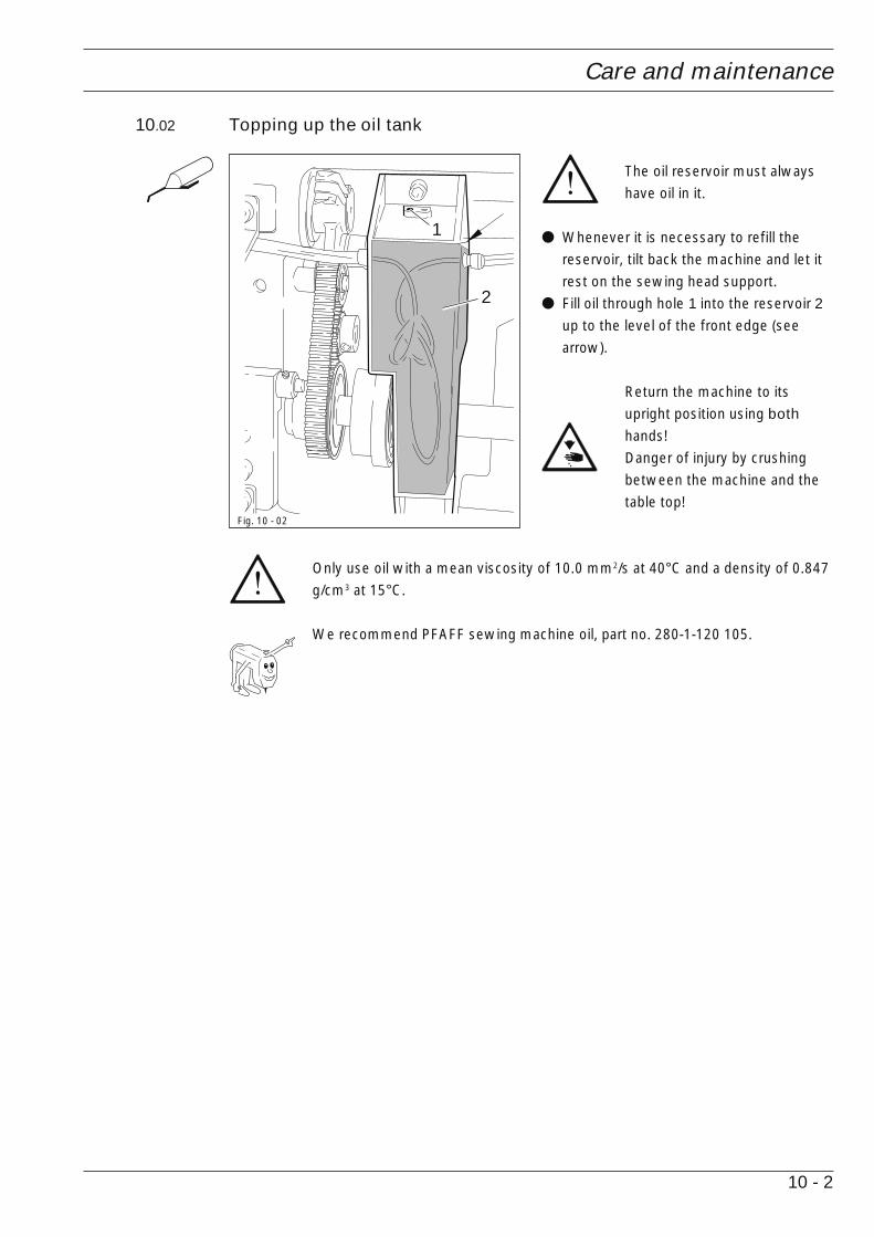
10.02 Topping up the oil tank
The oil reservoir must alwayshave oil in it.
● Whenever it is necessary to refill thereservoir, tilt back the machine and let itrest on the sewing head support.
● Fill oil through hole 1 into the reservoir 2up to the level of the front edge (seearrow).
Return the machine to itsupright position using both
hands!Danger of injury by crushingbetween the machine and thetable top!
Only use oil with a mean viscosity of 10.0 mm2/s at 40°C and a density of 0.847g/cm3 at 15°C.
We recommend PFAFF sewing machine oil, part no. 280-1-120 105.
Fig. 10 - 02
2
1
Wearing parts
11 - 1
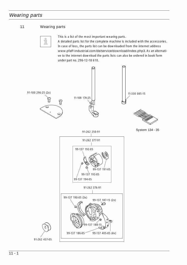
91-262 250-91
91-262 376-91
99-137 187-15 (2x)
99-137 186-05 99-137 405-05 (4x)
99-137 188-15
99-137 190-05 (3x)
91-262 377-91
99-137 192-05
99-137 194-05
99-137 193-05
99-137 191-05
91-262 437-05
91-100 296-25 (2x)
11-108 174-2511-330 085-15
11 Wearing parts
This is a list of the most important wearing parts.A detailed parts list for the complete machine is included with the accessories.In case of loss, the parts list can be downloaded from the internet addresswww.pfaff-industrial.com/de/service/download/index.php3. As an alternati-ve to the internet download the parts lists can also be ordered in book formunder part no. 296-12-18 610.
System 134 - 35

Wearing parts
11 - 2
99-137 151-45
91-171 049-05
91-171 042-05
11-108 087-15
91-262 235-15
91-171 853-15
91-108 222-15
91-264 240-15
11-108 084-15 (2x)

© P
FAFF
Indu
strie
syst
eme
und
Mas
chin
en A
G 2
009,
PFA
FF is
the
exc
lusi
ve t
rade
mar
k of
VS
M G
roup
AB
.PFA
FF In
dust
riesy
stem
e un
d M
asch
inen
AG
is a
n au
thor
ized
lice
nsee
of
the
PFA
FF t
rade
mar
k.
PFAFF Industriesysteme und Maschinen AG
Hans-Geiger-Str. 12 - IG NordD-67661 Kaiserslautern
Telefon: +49 - 6301 3205 - 0
Telefax: +49 - 6301 3205 - 1386
E-mail: [email protected]
Gedruckt in der BRD / Printed in Germany / Imprimé en la R.F.A. / Impreso en la R.F.A