permanent magnet synchronous generator based … · international research journal of engineering...
TRANSCRIPT
International Research Journal of Engineering and Technology (IRJET) e-ISSN: 2395 -0056
Volume: 03 Issue: 06 | June-2016 www.irjet.net p-ISSN: 2395-0072
© 2016, IRJET | Impact Factor value: 4.45 | ISO 9001:2008 Certified Journal | Page 995
Permanent Magnet Synchronous Generator Based Energy Conversion
System: A Review
Bhawna Gupta1, Gagan Deep Yadav2
1 M-Tech Scholar, EE Department, YIET, Gadhauli, India 2 Assistant Professor, EE Department, YIET, Gadhauli, India
---------------------------------------------------------------------***---------------------------------------------------------------------
Abstract - This paper presents a comprehensive review on study of modeling and simulation of permanent magnet synchronous generator based on wind energy conversion system, in which the basic wind energy conversion equation, wind turbine mathematical equation, wind turbine controls, and drive train are discussed, the PMSG (permanent magnet synchronous generator is introduced as construction, mathematical equation of PMSG are established in the d-q model, and different types of wind generator concept in short is discussed, configuration of different power converter‘s is proposed with modeling and simulation of PMSG based on WECS at variable speed operation and maximum power capture, various control technique for the system are discussed for both machine-side and grid-side in detail, the different types of MPPT technique is presented in this paper. Key Words: wind energy conversion, wind turbine, drive train, permanent magnet synchronous generator, converter topology, MPPT Methodology.
1. INTRODUCTION Wind power is an important renewable energy resource and the fastest growing technology amongst different renewable energy generation technologies [1].wind energy conversion system consist of wind turbine, pitch angle control, drive train , generator and power converter. There are various kinds of generators used in WECS such as induction generator (IG), double feed induction generator (DFIG) and permanent magnet synchronous generator (PMSG). The PMSG based on WECS can connect to the turbine without using gearbox. The gearbox causes in the cost maintenance and then it will decrease the weight of nacelle. [2] many developed generation systems are used to extract maximum wind energy. Optimum wind energy extraction is achieved by running wind turbine generator in a variable speed mode because of the higher energy gain and reduced losses and stresses [3]. Wind turbines are classified with a view to the rotational speed, the power regulation, and the generator system. When considering the construction of the direct drive system, the turbines are classified in to the geared and the direct-driven types [4, 5]. The direct-drive type is known with its advantages, as it has a lower cost, smaller size, and
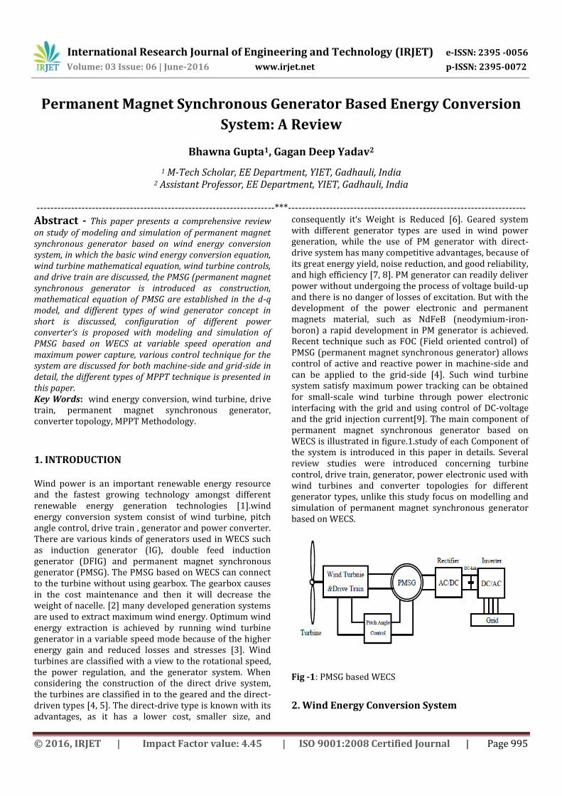
consequently it‘s Weight is Reduced [6]. Geared system with different generator types are used in wind power generation, while the use of PM generator with direct-drive system has many competitive advantages, because of its great energy yield, noise reduction, and good reliability, and high efficiency [7, 8]. PM generator can readily deliver power without undergoing the process of voltage build-up and there is no danger of losses of excitation. But with the development of the power electronic and permanent magnets material, such as NdFeB (neodymium-iron-boron) a rapid development in PM generator is achieved. Recent technique such as FOC (Field oriented control) of PMSG (permanent magnet synchronous generator) allows control of active and reactive power in machine-side and can be applied to the grid-side [4]. Such wind turbine system satisfy maximum power tracking can be obtained for small-scale wind turbine through power electronic interfacing with the grid and using control of DC-voltage and the grid injection current[9]. The main component of permanent magnet synchronous generator based on WECS is illustrated in figure.1.study of each Component of the system is introduced in this paper in details. Several review studies were introduced concerning turbine control, drive train, generator, power electronic used with wind turbines and converter topologies for different generator types, unlike this study focus on modelling and simulation of permanent magnet synchronous generator based on WECS.
Fig -1: PMSG based WECS
2. Wind Energy Conversion System
International Research Journal of Engineering and Technology (IRJET) e-ISSN: 2395 -0056
Volume: 03 Issue: 06 | June-2016 www.irjet.net p-ISSN: 2395-0072
© 2016, IRJET | Impact Factor value: 4.45 | ISO 9001:2008 Certified Journal | Page 996
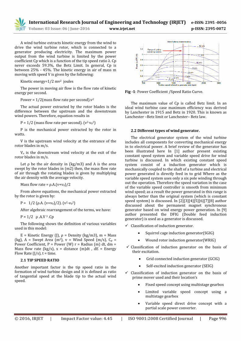
A wind turbine extracts kinetic energy from the wind to drive the wind turbine rotor, which is connected to a generator producing electricity. The maximum power output from the wind turbine is limited by the power coefficient Cp which is a function of the tip speed ratio λ. Cp never exceeds 59.3%, the Betz Limit. In general, Cp is between 25% - 45%. The kinetic energy in air of mass m moving with speed V is given by the following:
Kinetic energy=1/2 mv2 joules
The power in moving air flow is the flow rate of kinetic energy per second.
Power = 1/2(mass flow rate per second).v2
The actual power extracted by the rotor blades is the difference between the upstream and the downstream wind powers. Therefore, equation results in
P = 1/2 (mass flow rate per second). (v2-v02)
P is the mechanical power extracted by the rotor in watts.
V is the upstream wind velocity at the entrance of the rotor blades in m/s.
Vo is the downstream wind velocity at the exit of the rotor blades in m/s.
Let ρ be the air density in (kg/m3) and A is the area swept by the rotor blades in (m2) then, the mass flow rate of air through the rotating blades is given by multiplying the air density with the average velocity.
Mass flow rate = ρ.A.(v+v0)/2
From above equations, the mechanical power extracted by the rotor is given by:
P = 1/2 (ρ.A. (v+v0)/2). (v2-v02)
After algebraic rearrangement of the terms, we have:
P = 1/2 ρ .A.V 3 .Cp
The following shows the definition of various variables used in this model:
E = Kinetic Energy (J), ρ = Density (kg/m3), m = Mass (kg), A = Swept Area (m2), v = Wind Speed (m/s), Cp = Power Coefficient, P = Power (W) r = Radius (m) dt, dm = Mass flow rate (kg/s), x = distance (m)dt , dE = Energy Flow Rate (J/s), t = time.
2.1 TIP SPEED RATIO
Another important factor is the tip speed ratio in the formation of wind turbine design and it is defined as ratio of tangential speed at the blade tip to the actual wind speed.
Fig -1: Power Coefficient /Speed Ratio Curve.
The maximum value of Cp is called Betz limit. In an ideal wind turbine case maximum efficiency was derived by Lanchester in 1915 and Betz in 1920. This is known as Lanchester –Betz limit or Lanchester– Betz law.
2.2 Different types of wind generator.
The electrical generator system of the wind turbine includes all components for converting mechanical energy in to electrical power. A brief review of the generator has been illustrated here In [1] author present existing constant speed system and variable speed drive for wind turbine is discussed. In which existing constant speed system consist of a induction generator which is mechanically coupled to the shaft of a turbine and electrical power generated is directly feed in to grid Where as the variable speed system uses only a six pole winding through out the operation. Therefore the speed variation in the case of the variable speed controller is smooth from minimum wind speed; as a result the power generated in this range is always better than the original system (which is constant speed system) is discussed. In [2][3][4][5][6][7][8] author discussed about the permanent magnet synchronous generator based on wind energy power generation. In [9] author presented the DFIG (Double feed induction generator) is used as a generator is discussed.
Classification of induction generator.
Squirrel cage induction generator(SGIG)
Wound rotor induction generator(WRIG)
Classification of induction generator on the basis of their excitation.
Grid connected induction generator (GCIG)
Self-excited induction generator (SEIG)
Classification of induction generator on the basis of prime mover used and their location‘s
Fixed speed concept using multistage gearbox
Limited variable speed concept using a multistage gearbox
Variable speed direct drive concept with a partial scale power converter.
International Research Journal of Engineering and Technology (IRJET) e-ISSN: 2395 -0056
Volume: 03 Issue: 06 | June-2016 www.irjet.net p-ISSN: 2395-0072
© 2016, IRJET | Impact Factor value: 4.45 | ISO 9001:2008 Certified Journal | Page 997
Variable speed direct drive concept with a full-scale power converter.
Electrical excited synchronous generator (EESG)
Permanent magnet synchronous generator (PMSG)
Types of permanent magnet machines.
Axial-flux PM machine: - produces magnetic flux in axial direction.
Radial-flux PM machine: - produces magnetic flux in radial direction.
Transversal-flux PM machine: - produces magnetic flux in perpendicular to the direction of rotor rotation.
Variable speed single stage geared concept with a full scale power converter
PM synchronous generator (PMSG)
Variable speed multiple stage geared concept with a full-scale power converter.
PM synchronous generator (PMSG)
Squirrel cage induction generator (SGIG)
Double feed induction generator (DFIG)
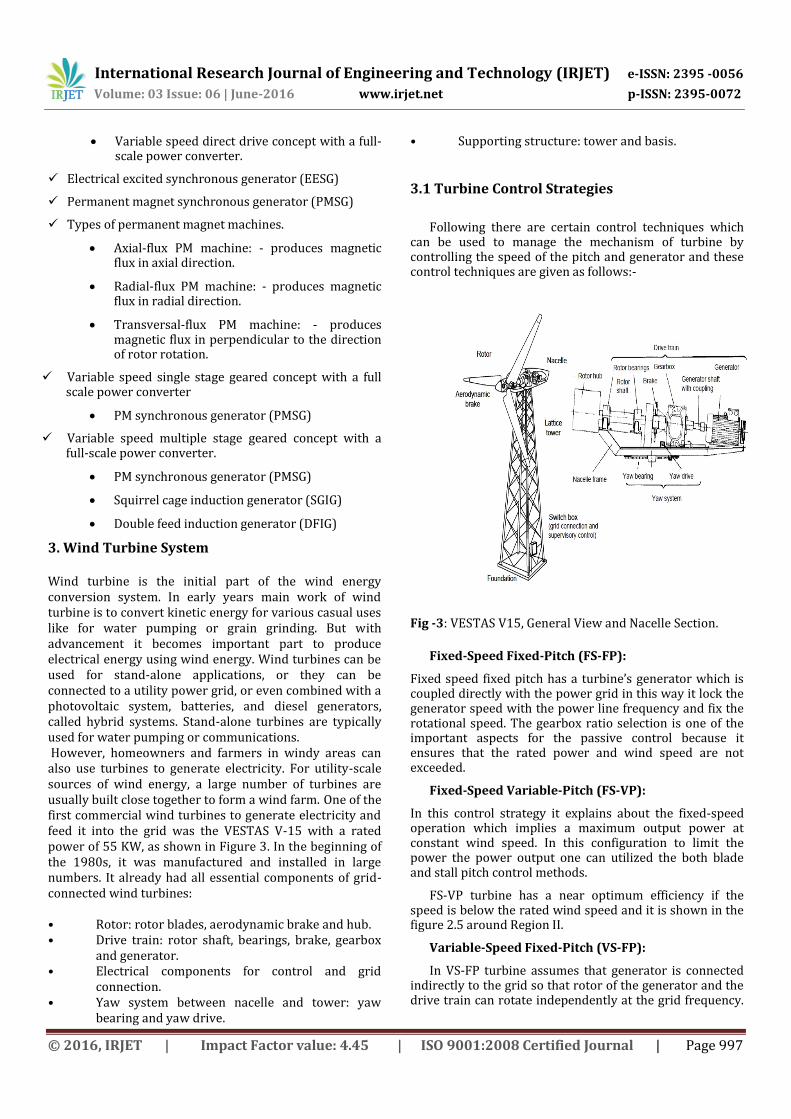
3. Wind Turbine System Wind turbine is the initial part of the wind energy conversion system. In early years main work of wind turbine is to convert kinetic energy for various casual uses like for water pumping or grain grinding. But with advancement it becomes important part to produce electrical energy using wind energy. Wind turbines can be used for stand-alone applications, or they can be connected to a utility power grid, or even combined with a photovoltaic system, batteries, and diesel generators, called hybrid systems. Stand-alone turbines are typically used for water pumping or communications. However, homeowners and farmers in windy areas can also use turbines to generate electricity. For utility-scale sources of wind energy, a large number of turbines are usually built close together to form a wind farm. One of the first commercial wind turbines to generate electricity and feed it into the grid was the VESTAS V-15 with a rated power of 55 KW, as shown in Figure 3. In the beginning of the 1980s, it was manufactured and installed in large numbers. It already had all essential components of grid-connected wind turbines: • Rotor: rotor blades, aerodynamic brake and hub. • Drive train: rotor shaft, bearings, brake, gearbox
and generator. • Electrical components for control and grid
connection. • Yaw system between nacelle and tower: yaw
bearing and yaw drive.
• Supporting structure: tower and basis.
3.1 Turbine Control Strategies
Following there are certain control techniques which can be used to manage the mechanism of turbine by controlling the speed of the pitch and generator and these control techniques are given as follows:-
Fig -3: VESTAS V15, General View and Nacelle Section.
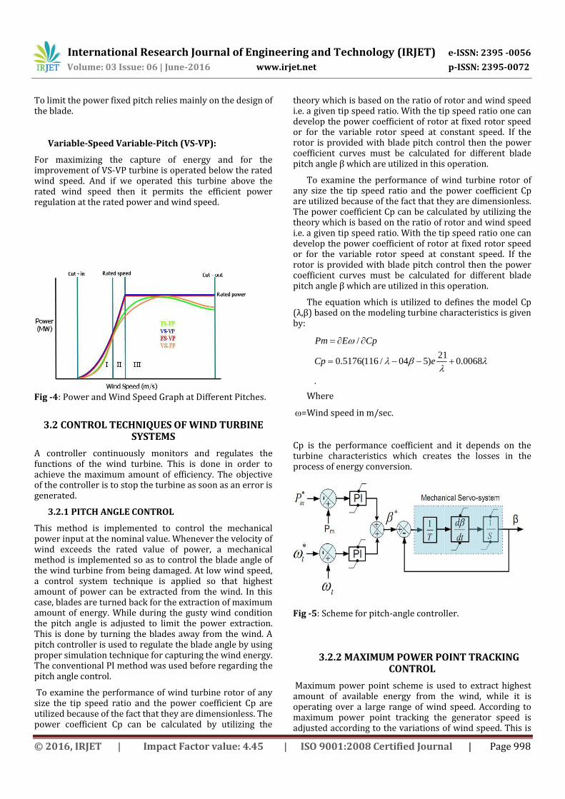
Fixed-Speed Fixed-Pitch (FS-FP):
Fixed speed fixed pitch has a turbine’s generator which is coupled directly with the power grid in this way it lock the generator speed with the power line frequency and fix the rotational speed. The gearbox ratio selection is one of the important aspects for the passive control because it ensures that the rated power and wind speed are not exceeded.
Fixed-Speed Variable-Pitch (FS-VP):
In this control strategy it explains about the fixed-speed operation which implies a maximum output power at constant wind speed. In this configuration to limit the power the power output one can utilized the both blade and stall pitch control methods.
FS-VP turbine has a near optimum efficiency if the speed is below the rated wind speed and it is shown in the figure 2.5 around Region II.
Variable-Speed Fixed-Pitch (VS-FP):
In VS-FP turbine assumes that generator is connected indirectly to the grid so that rotor of the generator and the drive train can rotate independently at the grid frequency.
International Research Journal of Engineering and Technology (IRJET) e-ISSN: 2395 -0056
Volume: 03 Issue: 06 | June-2016 www.irjet.net p-ISSN: 2395-0072
© 2016, IRJET | Impact Factor value: 4.45 | ISO 9001:2008 Certified Journal | Page 998
To limit the power fixed pitch relies mainly on the design of the blade.
Variable-Speed Variable-Pitch (VS-VP):
For maximizing the capture of energy and for the improvement of VS-VP turbine is operated below the rated wind speed. And if we operated this turbine above the rated wind speed then it permits the efficient power regulation at the rated power and wind speed.
Fig -4: Power and Wind Speed Graph at Different Pitches.
3.2 CONTROL TECHNIQUES OF WIND TURBINE SYSTEMS
A controller continuously monitors and regulates the functions of the wind turbine. This is done in order to achieve the maximum amount of efficiency. The objective of the controller is to stop the turbine as soon as an error is generated.
3.2.1 PITCH ANGLE CONTROL
This method is implemented to control the mechanical power input at the nominal value. Whenever the velocity of wind exceeds the rated value of power, a mechanical method is implemented so as to control the blade angle of the wind turbine from being damaged. At low wind speed, a control system technique is applied so that highest amount of power can be extracted from the wind. In this case, blades are turned back for the extraction of maximum amount of energy. While during the gusty wind condition the pitch angle is adjusted to limit the power extraction. This is done by turning the blades away from the wind. A pitch controller is used to regulate the blade angle by using proper simulation technique for capturing the wind energy. The conventional PI method was used before regarding the pitch angle control.
To examine the performance of wind turbine rotor of any size the tip speed ratio and the power coefficient Cp are utilized because of the fact that they are dimensionless. The power coefficient Cp can be calculated by utilizing the
theory which is based on the ratio of rotor and wind speed i.e. a given tip speed ratio. With the tip speed ratio one can develop the power coefficient of rotor at fixed rotor speed or for the variable rotor speed at constant speed. If the rotor is provided with blade pitch control then the power coefficient curves must be calculated for different blade pitch angle β which are utilized in this operation.
To examine the performance of wind turbine rotor of any size the tip speed ratio and the power coefficient Cp are utilized because of the fact that they are dimensionless. The power coefficient Cp can be calculated by utilizing the theory which is based on the ratio of rotor and wind speed i.e. a given tip speed ratio. With the tip speed ratio one can develop the power coefficient of rotor at fixed rotor speed or for the variable rotor speed at constant speed. If the rotor is provided with blade pitch control then the power coefficient curves must be calculated for different blade pitch angle β which are utilized in this operation.
The equation which is utilized to defines the model Cp (λ,β) based on the modeling turbine characteristics is given by:
.
0068.021
)504/116(5176.0
/
eCp
CpEPm
Where
=Wind speed in m/sec.
Cp is the performance coefficient and it depends on the turbine characteristics which creates the losses in the process of energy conversion.
Fig -5: Scheme for pitch-angle controller.
3.2.2 MAXIMUM POWER POINT TRACKING CONTROL
Maximum power point scheme is used to extract highest amount of available energy from the wind, while it is operating over a large range of wind speed. According to maximum power point tracking the generator speed is adjusted according to the variations of wind speed. This is
International Research Journal of Engineering and Technology (IRJET) e-ISSN: 2395 -0056
Volume: 03 Issue: 06 | June-2016 www.irjet.net p-ISSN: 2395-0072
© 2016, IRJET | Impact Factor value: 4.45 | ISO 9001:2008 Certified Journal | Page 999
done so that the tip speed relation can be maintained at its optimal value λ. The conventional control schemes included the control mode of operation which used to depend on the setting of reference values.
4. Coupling
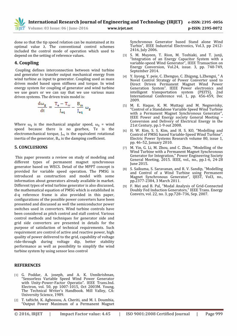
Coupling defines interconnection between wind turbine and generator to transfer output mechanical energy from wind turbine as input to generator. Coupling used as mass driven model based upon stiffness and torque. In wind energy system for coupling of generator and wind turbine we use gears or we can say that we use various mass driven systems. The driven train model is:
Where ωg is the mechanical angular speed, ωg = wind speed because there is no gearbox, Te is the electromechanical torque, Jeq is the equivalent rotational inertia of the generator, Bm is the damping coefficient.
5. CONCLUSIONS This paper presents a review on study of modeling and different types of permanent magnet synchronous generator based on WECS. Detail of the MPPT concept is provided for variable speed operation. The PMSG is introduced as construction and model with some information about generators already available in market. Different types of wind turbine generator is also discussed, the mathematical equation of PMSG which is established in d-q reference frame is also provided in this paper, configurations of the possible power converters have been presented and discussed as well the semiconductor power switches used in converters. Wind turbine controls have been considered as pitch control and stall control. Various control methods and techniques for generator side and grid side converters are presented in details for the purpose of satisfaction of technical requirements. Such requirement are control of active and reactive power, high quality of power delivered to the grid, capability of voltage ride-through during voltage dip, better stability performance as well as possibility to simplify the wind turbine system by using sensor less control
REFERENCES [1] G. Poddar, A. joseph, and A. K. Unnikrishnan,
“Sensorless Variable Speed Wind Power Generator with Unity-Power-Factor Operatio”. IEEE Trans.Ind. Electron, vol. 50, pp 1007-1015, Oct 2003M. Young, The Technical Writer’s Handbook. Mill Valley, CA: University Science, 1989.
[2] T. tafticht, K. Agbossou, A. Cheriti, and M. I. Doumbia, “Output Power Maximum of a Permanent Magnet
Synchronous Generator based Stand alone Wind Turbin”, IEEE Industrial Electronics, Vol.3, pp 2412-2416, July 2006.
[3] S. M. Muyeen, T. Rion, M. Toshiaki, and T. junji, “Integration of an Energy Capacitor System with a variable-speed Wind Generator”, IEEE Transaction on Energy Conversion, Vol.24, issue. 3, pp. 740-749, September 2014.
[4] Y. liyong, Y. peie, C. Zhenguo, C. Zhigang, L.Zhengxi, “ A Novel Control Strategy of Power Converter used to Direct Driven Permanent Magnet Wind Power Generation System”. IEEE Power electronics and intelligent transportation system (PEITS), 2nd International Conference vol. 1, pp. 456-459, Dec 2009.
[5] M. E. Haque, K. M. Muttaqi and M. Negnevisky, “Control of a Standalone Variable Speed Wind Turbine with a Permanent Magnet Synchronous Generator”, IEEE Power and Energy society General Meeting – Conversion and Delivery of Electrical Energy in the 21st Century, pp.1-9 out 2008.
[6] H. W. Kim, S. S. Kim, and H. S. KO, “Modelling and Control of PMSG based Variable-Speed Wind Turbine”. Electric Power Systems Research volume 80, issue 1, pp. 46–52, January 2010.
[7] M. Yin, G. Li, M. Zhou, and C. Zhao, "Modelling of the Wind Turbine with a Permanent Magnet Synchronous Generator for Integration,” Power Engineering Society General Meeting, 2015. IEEE, vol., no., pp.1-6, 24-28 June 2015.
[8] S. Saikuma, S. Saravanan, and R. V. Sandip, “Modelling and Control of a Wind Turbine using Permanent Magnet Synchronous Generator”, IJEST, Vol3, no., pp.2377-2384, 3 March 2011.
[9] F. Mei and B. Pal, “Modal Analysis of Grid-Connected Doubly Fed Induction Generators,” IEEE Trans. Energy Convers, vol. 22, no. 3, pp.728–736, Sep. 2007.