technical diary of stage-2 (unit-3&4) … heat input per plan area of (kcal/m /hr) 280000000...
TRANSCRIPT

2X110 MW, UNIT-3&4, STAGE –II, PANIPAT THERMAL POWER STATION, PANIPAT
1
TECHNICAL
DIARY
OF
STAGE-2
(UNIT-3&4)
(PTPS,Panipat)
2X110 MW, UNIT-3&4, STAGE –II, PANIPAT THERMAL POWER STATION, PANIPAT
2
INDEX
Contents Page no.
1. Boiler and its auxiliaries 4-17
2 Ash Handling System 18-19
3 DM Plant 20-24
4 Fuel Oil System 25-26
5 Turbine & its Auxillaries 27-41
6 Compress Air System 42-43
7. C & I System 44-50
8 Generator & Electrical System 51-72
9 Fire Protection System
10 Fire Tender System
2X110 MW, UNIT-3&4, STAGE –II, PANIPAT THERMAL POWER STATION, PANIPAT
3
BOILER
AND
ITS AUXILIARIES

2X110 MW, UNIT-3&4, STAGE –II, PANIPAT THERMAL POWER STATION, PANIPAT
4
Max Boiler
53.858
MTR
Column Height
Total No of ----
Columns
Total No of ----.
Ceiling Girder
Max Wt of -----
Ceiling
Girder (L-Row)
Total Wt of -----
Boiler Structure
Wt of Drum -----
Total Wt of -----
Pressure Parts
Other Non
Pressure Parts -----
(APH,
Insulation &
Ducting
Furnace 10.135
Dimension MTR ,
(W*D*H) 7.696
MTR ,
29.487
MTR
- -

5
Type : Tilting Tangential Burner, Balanced Draft, Fusion welded furnace, Natural Circulation, Dry Bottom Ash with direct fired pulveriser coal from coal mills and with steam reheating arrangement
Manufacturer: BHEL. Designed Fuel: Indian Bituminous Coal
1 STEAM GENERATOR WITH 100% 100%
AUXILIARIES BMCR TMCR
1.1
Steam flow at final super heater
(TPH) 375
outlet
Maximum continuous generation at
1.2 VWO conditions with offered steam (TPH)
110 (VWO)
parameters at super heater
outlet
Auxiliary steam flow for Soot Steam for soot blowing is from Final
1.4
blowing, Oil Burner atomization etc.
super heater outlet and steam for oil burner
atomization is from Aux. Steam header.
During normal operation, no steam from
Aux. Steam header is required for soot
blowing and oil burner atomization
Steam for auxiliary steam tap off
Kg/cm2/deg
a)
1) Final Super heater Outlet
138.0/540
cent
Pr./Temp.
Kg/cm2/deg
2)Platen Super Heater Outlet
138.0/504
cent
Pr./Temp
b) Aux.
Steam For oil
burner Kg/cm2/De 11/24
0
Atomization.
g cent
1.5
Thermal efficiency of the
steam (%) 87.5
generating units
1.6 Steam pressure at final super kg/cm2 (a) 138.0

6
heater
outlet
1.7
Steam temperature at final super (°C)
540.0
heater outlet
1.8 Reheater outlet steam flow
TPH 313.0
1.9 Steam temperature at Reheater inlet (°C)
369.0
header
1.10 Steam temperature at Reheater (°C)
540.0
outlet header
1.11 Steam pressure at Reheater inlet kg/cm2 (a )
34.50
header
1.12 Steam pressure at Reheater outlet kg/cm2 (a ) 32.70
header
1.13 a) Pressure drop across Reheater (kg/cm2)
1.8
b) Pressure drop in economizer hot reheat lines (kg/cm2) 1.3
1.15 a) Feed water temperature at (°C) 240.0
Economizer inlet
b) Feed water temp. Of economizer (oC) 288.0
outlet
1.16 Boiler drum:
a) Elevation M
45,500
d) Diameter / thickness mm ID = 1524, Th. =
125

7
h) Design Temperature oC
340
Water capacity at MCR between m3
i) normal and lowest water level 8.0
1.17 Number of Attemperators:
a) Superheated steam 2
b) Reheat steam 2
1.18 Flue Gas Temperature º C
a) Platen Superheaters inlet/ outlet (oC)
1128/1048
b) Final superheaters inlet/ outlet (oC)
824/761
c) Reheater finish inlet / outlet (oC)
1048/890
d) SH low temperature inlet/ outlet (oC)
761/507
f) Economizer inlet / outlet (oC)
507/358
g) Air Heater inlet / outlet (oC)
358/144
Temperature difference across the oC
e) drum metal thickness. NA
f) Maximum operating pressure Kg /cm2 (g) 148.8
g) Design pressure Kg /cm2 (g)
158.2

8
h) ESP inlet/outlet (oC)
130/125
i) ID fan inlet/ outlet (oC)
125/124
j) Stack Inlet (oC)
100% TMCR:121(performance coal)/ 120
(worst coal)
Pressure Drop: mmWC
80
100
80%B
100
1.19
%BMC
%TMCR
%TMCR
MCR
R
Primary air side total pressure drop
a) through the system mmWC NA 736
Secondary air side total pressure
b) drop mmWC NA 434
c) Flue gas pressure drop through the
mmWC
NA 328
system
1.21 Steam Purity (ppm)
Total Dissolved solids
Will not exceed .02 ppm when the total
a) dissolved solid is not greater than 20 ppm in
drum.
b) Silica PPB
0.02ppm (max.)
b) Sodium
PPB
0.01 ppm (max.)
1.23 Cooling Water Requirement for Boilers & Auxiliaries
a) Quantity M3/hr
184.40
1.24 Instrument air & Service air Requirement
Quantity (for boiler, turbine & NM3/min/
a) auxiliaries) for one unit Unit 20
9
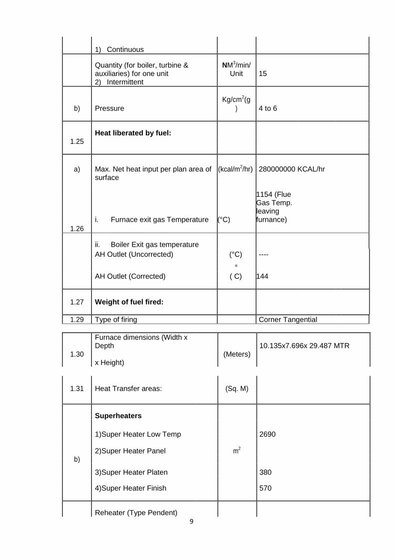
1) Continuous
Quantity (for boiler, turbine & NM3/min/ auxiliaries) for one unit Unit 15 2) Intermittent
Pressure
Kg/cm2(g
b) ) 4 to 6
1.25 Heat liberated by fuel:
a) Max. Net heat input per plan area of (kcal/m2/hr) 280000000 KCAL/hr surface
1.26
i. Furnace exit gas Temperature (°C)
1154 (Flue Gas Temp. leaving furnance)
ii. Boiler Exit gas temperature
AH Outlet (Uncorrected) (°C) ----
AH Outlet (Corrected)
°
( C) 144
1.27 Weight of fuel fired:
1.29 Type of firing Corner Tangential
1.30
Furnace dimensions (Width x Depth
(Meters) 10.135x7.696x 29.487 MTR
x Height)
1.31 Heat Transfer areas: (Sq. M)
Superheaters
1)Super Heater Low Temp 2690
b) 2)Super Heater Panel m2
3)Super Heater Platen 380
4)Super Heater Finish 570
Reheater (Type Pendent)

10
1)Reheater wall m2
1060
c)
d) Economizers(Type continous finned tube) m2
3233
e) Air heater(Roatry)
m2 16800
f) Steam coil air heater m2 NA
g) Max. air leakage through air heater %
12
1.32 Soot-blowers:
1)10, Short Rotary, Single nozzle, RW5E, Retractable type, For furnace chamber at Unit-3 only.
a) Quantity, Type, Location
1) Short retractable soot blower P-30 Kg/Cm2
T= 300 deg cent
b) Steam Conditions (Pr. & Temp
quality)
< 3 min
c) Time required for one cycle of
operation
Cleaning Medium
Steam
a) Pressure : Kg/cm2
d) 10.5
b) Temperature : deg.
C
300
c) Source of cleaning medium
STEAM
To be decided based on control

11
logic of the
e) Number of groups of soot blowers system.
To be decided based on control logic of the
f) Total operating time per group min system.
Blowers
Rehea
Econ Super
Furnac
e
Omis
ter
heater
Er
Type & Qty. SRSB RW5E
g)
AHLW 4
SRSB
10 (Unit-3)
c) Operating pressure Kg/cm2 AHLW 10.5
SRSB 10.5
h) Materials of Construction
1.34 HP & LP CHEMICAL DOSING
Phosphate Hydrazine
Ammo
nia
SYSTEM
a) Quantity Set 3 3 NA
b) Type Simplex,
Plunger Simplex, Plunger
NA
c) Medium to be handled Sodium
phosphate Hydrazine
NA
d) Capacity Lit/min 65 20 NA
e) Discharge pressure Kg/cm2 175 25 NA
f) Stroke Adjustment Range 0~100 0~100 NA
g) Stroke adjustment yes yes

12
NA
i) Liquid end 316SS PTFE NA
j) Plunger 316SS 316SS NA
k) Drive end 316 PVDF NA
l) End Connection NPT NPT NA
1.35 Pulverizers:
Quantity, type, make 12 nos. , XRP-623, BHEL a)
b) Speed
RPM 62
c) Design capacity TPH 16.5
d) Motor rating KW 200
e) Motor speed RPM 986
Number of operating mills and f) standby mills
i) Working 5
ii) Standby 1
1.36 Coal Feeders:
a) Type, Quantity, make Pressurised ,volumetric rotary feeders with PIV Variator, 12 nos., flender make ,supplied by BHEL
Model
b) Feed Rate T / hr 20
d) Speed regulating range RPM Piv
Type of Control

13
e) 1)Microprocessor PIV 2)Frequency conversion
1.37 Burners Coal
Fuel oil Light oil
Igniters
HFO
Quantity, type, make 24 12 steam atomization
NIL 12 High Energy Arc Type
b) Capacity each (10 kg/hr) 7.5% MCR --
c) Turn down Ratio NA
1.38 Stacks
c) No. Of stacks provided m 1 with twin flue
1.39 Air Preheater( REGERATIVE AIR PREHEATER TRISECTOR type)
1.39.1 Type TRISECTOR TYPE
1.39.2 Number 2
1.39.3 Mounting (Vertical / Horizontal) Vertical
1.39.4 Maximum Handling Capacity 16800 M2
Flue gas temperature at heaters
1.39.5 outlet
Corrected
Deg. C
144
Uncorrected
1.39.6 Max. Air leakage through air heater %
12
1.39.8 Pressure drop at BMCR,
a) Air side (primary) 736 MMWCL

14
b) Air side(secondary)
434 MMWCL
Emergency drive for Air heater
Air motor
1.39.9 Primary Air temperature Deg. C AMBIENT/315
1.39.10 Secondary Air temperature Deg. C AMBIENT/307
1.39.11 Flue Gas temperature Deg. C 358/144
1.42 Water wall details
Total heating surface area Sq.M
42.1 Front Wall Panels NA
No. of tubes (WW tubes)
REAR & FRONT = 133 EACH SIDE LHS & RHS = 85 EACH SIDE TOTAL = 436
OD mm 63.5
Pitch mm 12
Wall thickness mm 5.6 to 6.3
Tube material SA210-A1/C
Membrane fin thickness mm 6
1.43 ESP
1. 43.1 ESP: One ESP for one boiler
a) Type; make 2FAA-7X32-12090-2
b) Collecting electrodes – material, 1.6 mm th.cold rolled M.S. Plate
type
c) Discharge electrodes – material, SPIRAL WITH HOOK SUPPORTS
type
d) Pressure drop across ESP mmwc
15

15
e) Temperature drop across ESP
oC NA
f) Quantity, type, rating of
14
transformer Rectifier units for one 70KV peak/800mA (MEAN)
ESP
g) Particulate emission with worst
mg/Nm3 150
coal firing with all fields in
service
h) Particulate emission with design
mg/Nm3 150
coal firing with all fields in
service
i) Particulate emission with design na
coal firing with one field out of mg/Nm3
service
j) ESP streams per boiler Nos 2
k) Specific collection area m2/m3/sec
164.53
l) Min. gas temp. At ESP inlet 1430C
m) Max. Flue gas velocity m/s 0.91
n) Storage capacity of each hopper M3 8 HRS CAPACITY
plate spacing
p) ESP inlet Flue gas temp.
o Cent 143
q) Guaranteed Efficiency %
99.52

16
1.43.2 Collection efficiency % Design coal Worst coal
a) All fields in service 99.52 NA
b) One field out of service in each NA NA
ESP
e) Flue gas flow m3/s 200.4
1. 43.3 Schedule of Weights:
1. 43.4 ESP NA
a) ESP Dimension m*m*m 2xFAA-7x32-12090-2
b) No. of fields per ESP No./Stream 7
c) Inlet Dust burden g/nm3 31.54
d) ESP design temp o Cent 143
e) Flue Gas treatment time sec 24.68
f) ESP Casing:- mm Carbon Steel
Material of construction
Thickness 6
1.44.1 FD, PA, ID Fan
Sno Description Unit FD Fan PA Fan ID Fan Scanner air fan
1 Make ,Qty, Type
BHEL, 2 nos per boiler, axial, AN 12 e 6
BHEL, 2 Nos per boiler, Radial, single suction NDFV-20b
BHEL, 3 Nos per boiler, radial, double suction, NDZV 28 SIDOR
Centrifugal 2 Nos per boiler,
2 Volumetric Flow m3
/sec 58 at 50 deg 40 at 50 deg 132 at sp gravity 0.833
1200
Rate per fan(Capacity
At design Point)
3 Total Pressure(Fan Mmwc 355 1275 280
200
Total Pressure rise)
5 Motor Rating KW 300 750 600 2
6 Speed Rpm 1450 1480 745 3000

17
7 Motor Type
BHEL Make SQ. Induction
8 Lubrication system Forced Oil Forced Oil Forced Oil NIL
10 No. Stages of Nos. 1 1 1 1 Impeller
11 Regulator Inlet guide vane control
Inlet guide vane control Hydraulic coupling
DAMPER
1.43.2 Details of Lube oil System
Sno. Description Unit PA ID Fan Fans
2 Pressure of lubricating oil Kg/Sq.m 8 max 1.5
4 Oil Temperature Deg.C 85/55 na
5 Capacity of Oil Tank leter 100 950
6 Degree of filtration um na na
7 Area of cooler Sq.M na na
9 Cooling water Pr. Kg/Sq/Cm 0.5 0.5
10 Power Of motor(415V) KW 0.372 8.3

18
3. ASH HANDLING SYSTEM

19
ASH HANDLING SYSTEM
S.N Description NO. provided ash collection Holding O per boiler rate Per boiler capacity
kg/hr(max) (hrs)
1) Furnace bottom ash hopper 01 7000 8
2) Economizer 04 421 Not provided
3) A.H. hoppers 04 421 Not provided
4) Duct hopper 02 260 Not provided
4) ESP. Hoppers 28
26089 8
5) Stack Hopper 01 23 Not provided
PUMPS SPECIFICATION
i) L.P. Ash water pumps
NO. of pumps 3
Location Ash water pump house
Capacity 911 m3/hr
Head 15MMWC
Suction pressure NA
R.P.M 1500 rpm
Motor 55 KW
ii) H.P ASH WATER PUMPS
NO. of pumps 4
Location Ash water pump house
Capacity 680 m3/hr
Head 120 MMWC
Suction pressure NA
R.P.M 1500 rpm
Motor 300 KW
iii) SEAL WATER PUMPS
NO. of pumps 2
Location Ash slurry pump house
Capacity 45 m3/hr
Head 130 MMWC
R.P.M 1500 rpm
Motor 30 KW
iv) ASH SLURRY PUMPS
NO. of pumps 6( 3+3)
Location Ash slurry pump house
Capacity 820 m3/hr
Head 24 MMWC
R.P.M 1000 rpm
Motor 110 KW

20

21
PRESSURE SAND FILTERS-POTABLE WATER (SFT-1)
No. of units = 3
Design rated Service flow rate = 58 m3/hr
Service cycle = 24hrs
Design velocity as per specification NA
Bed depth
Sand -16/32
Under bed
Free board
Vessel size =Dia-2800mm, HOS-1350mm, Pr.-7.0 Kg/Cm2
PRESSURE SAND FILTERS –DM (SFT-2)
No. of units = 2
Gross output of PSF NA
Design velocity as per specification NA
Design flow = 22 m3/hr
Bed depth NA
Sand -16/32 NA
Under bed NA
Free board NA
Vessel size = Dia-2400mm, HOS-1350mm, Pr.-7.0 Kg/Cm2
FILTER AIR BLOWERS (FTB)
Number = two-(Common)
Type = Rotary - ONE
Capacity (SUCTION) = 228 m3/hr
Air velocity required for PSF
Air pressure required (DISCHARGE PRESSURE) = 0.25 Kg/Cm2
Capacity
Material of construction = CI
DEGASSER AIR BLOWERS (DCB)
Number = Two
Type = centrifugal
Air velocity required for DGT NA
Air pressure required = 100 mm WC
Capacity = 1260m3/ hr
Material of construction = MS
DEGASSED WATER PUMP (DWP)
Number = Four
Type = Horizontal centrifugal
Capacity of pump = 35m3/hr
Head provided = 50 M
Material of construction = SS316
DEGASSED / DECARBONATED WATER STORAGE TANK (CWS)
Quantity = two
Capacity NA
Type = Horizontal Cylindrical
Size of unit = 3.0mx4.0m HOS/LOS

22
Material of construction = RCC
MIXED BED AIR BLOWERS (MBB)
Number = two
Type = Rotary - One
Air velocity required for MB NA
Air pressure required (DISCHARGE) 0.5 Kg / cm2
Capacity of blower = 150 m3/hr
Material of construction = CI
DEMINERALISED WATER STORAGE TANK (DWS-1)
Quantity = TWO
Capacity = 1000 m3as per specification
Type = Vertical cylindrical
Diameter selected = 8.0m
Size of unit Dia= 8.0m, HOS/LOS=10.5m
BULK ACID STORAGE TANKS (HLS)
Quantity = two
Capacity = 30 MT
Type = Horizontal Cylindrical
Size of unit = 2.0m DIA x3.5m HOS/LOS
MOC Mild steel rubber line-MSRL
BULK ALKALI STORAGE TANK (CSS)
Quantity = two
Capacity = 10m3 as per specification
Type = Horizontal Cylindrical
Size of unit = 2.0m DIA x3.5m HOS/LOS
MOC Mild steel rubber line-MSRL
DM REGENERATION PUMPS / DM WATER TRANSFER PUMP (DWP)
Number = two
Type = Horizontal centrifugal
Capacity = 40 m3/hr
Head provided = 28.5 M
Material of construction = C.I.
ACID UNLODING / TRANSFER PUMPS (HLP)
Number = two
Type = Horizontal centrifugal
Capacity as per specification = 10m3
Head provided as per specification = 15 MLC
Material of construction = pp-Polypropylene
ALKALI UNLODING PUMPS / CAUSTIC SODA TRANSFER PUMP (CSP)
Number = two
Type = Horizontal centrifugal
Capacity as per specification = 10 m3/hr
Head = 15 MLC
Material of construction = C.I.

23
ACID MEASURING TANK –SAC(HLM-1)
Number = one
Capacity = regeneration volume required for
regeneration one of unit plus 25%margin
100% HCL required NA
Concentration in regeneration tank = 30% to 10%
Volume of 30% concentration acid with 25% Margin = 2.58m3
Size of unit = 1.8.m Dia x1.5m HOS/LOS
ACID MEASURING TANK –MB(HLM-2)
Number = One
Capacity = Regeneration volume required for
regeneration of one unit plus 25%
Margin
100% HCL required = 290 Liters
Concentration in regeneration tank = 30% to 10%
Volume of tank with 25% margin = 0.255m3
Size of unit = 0.8m Dia x0.9m HOS/LOS
Concentration of alkali in the tank
Volume of 30% concentration solution
Size of unit
ALKALI MEASURING TANK – SBA (CSM-1)
Number = One
Capacity = Regeneration volume required for
regeneration of one unit plus 25%
margin.
100% NaOH required = 664 Lit. as 30%W/V
Concentration in regeneration tank = 45% to 30%
Volume of 30% concentration solution = 0.708 m3
Size of unit = 1.2mDia x1.0m HOS/LOS
ALKALI MEASURING TANK –MB(CSM-2)
Number = ONE
Capacity = Regeneration volume Required for regeneration of one
unit plus 25% margin
100% NaOH required = 180 Lit. as 30%W/V
Concentration in regeneration tank = 45% to 30%
Volume of 30% concentration solution = 0.3858 m3
Size of unit = 0.6m Dia x1.0m HOS/LOS
ALKALI MEASURING TANK –NEUTRALISATION (CPS)
Number = one
100% NaOH required = 650 Liters
Concentration of alkali in the tank = 45%

24
Volume of 48% concentration solution NA
Size of unit = 1.0mDia x 1.0 m Ht
NEUTRALISATION PIT (SEF)
Quantity = one
Number of section/Compartments = two
Effective capacity per section required = 492.66 m3
Size of section = 13.8x10.2x3.5 m3
EFFLUENT TRANSFER PUMPS (EWP)
Number = two
Type = Horizontal centrifugal
Capacity as per specification = 150 m3/hr
Head provided = 25 MLC
Material of construction = SS316

25
FUEL OIL SYSTEM
Description Fuel oil transfer Drain
Service HFO
Nos 2 nos per boiler (4 nos)
Type Multi screw positive displacement
Type of Duty Continuous
Capacity (m3/hr) 220
Make Tushaco
Head (Kg/Cm2) 20
Pump RPM 2900
KW 15
Pump efficiency % __NA
Sealing Mechanical
Bearing NA
FUEL OIL CHARACTERISTICS
Characteristics
Heavy Furnace Oil IS-1593-
Low Sulfur Heavy Stock
1971 Grade HV (LSHS)
Total sulfur content 3.5 – 4 - 4.5% max by Weight 1.0% max
Gross calorific value (kcal/kg) ~11,000 ~ 11,000
Flash point 66ºC min 93ºC min
Water content by vol 1.25% max 1.0% max
Sediment by weight 0.25% max 0.25% max
Asphaltene content by wt 2.5% max 2.5% max
Kinematic viscosity, CSt at 50ºC 370 max 500 max
Ash content by weight 0.1% max 0.1% max
Acidity (inorganic) Nil Nil
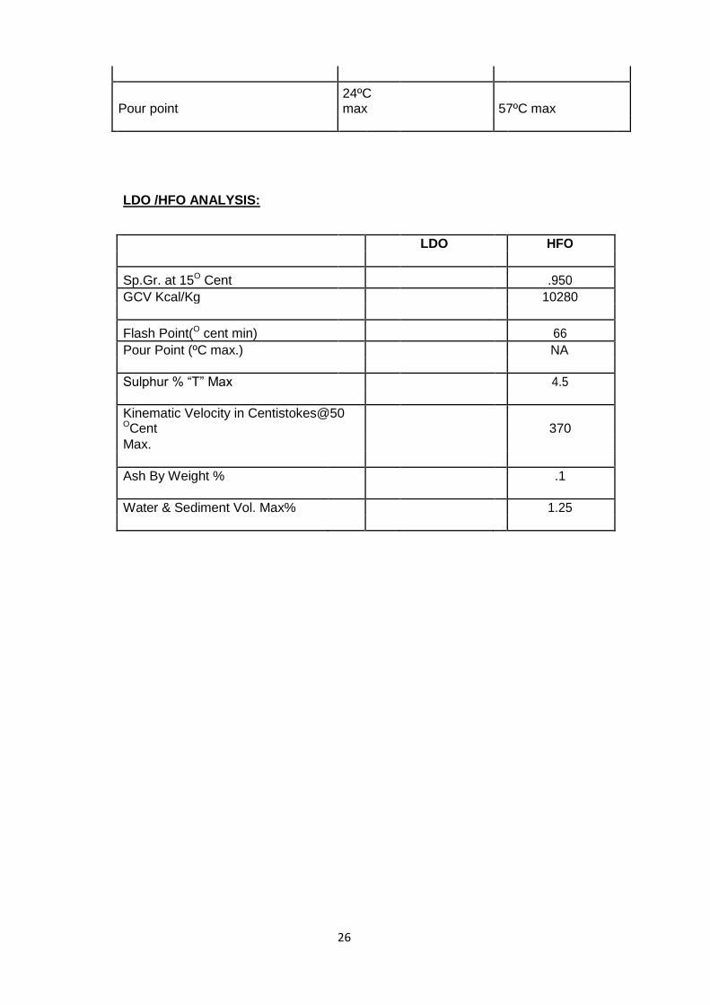
26
Pour point 24ºC max 57ºC max
LDO /HFO ANALYSIS:
LDO HFO
Sp.Gr. at 15O Cent .950
GCV Kcal/Kg 10280
Flash Point(O cent min) 66
Pour Point (ºC max.) NA
Sulphur % “T” Max 4.5
Kinematic Velocity in Centistokes@50 OCent 370
Max.
Ash By Weight % .1
Water & Sediment Vol. Max% 1.25

27
2X110MW, UNIT- 3&4 PANIPAT THERMAL POWER STATION, PANIPAT,
Turbine & its Auxillaries
2.1 STEAM TURBINE
I) Make / Type BHEL make, three cylinder, impulse type, condensing turbine with one reheat and eight (8) non regulating extractions
II) Type of governing Hydraulic control system
III) Rated output measured at the terminals of the generator as per CNS 080030
KW 110,000
IV) Economical output (at rated parameters)
KW 95,000
V) Rated speed RPM 3000
VI) Rated steam pressure just before the stop valve
ata 130
VII) Maximum steam pressure just before the stop valve
ata 146 (short period)
VIII) Rated steam temperature before the stop valve
°C 535 (transient condition)
IX) Maximum steam temperature before the stop valve
°C 545
X) Rated pressure of steam before the MP casing
ata 31.63
XI) Maximum pressure of steam before the MP casing
ata 35
XII) Rated temperature of steam before MP casing
°C 535
XIII) Maximum temperature of steam before MP casing
°C 545
XIV) No. of non-regulated extractions
nos. 8
XV) Temperature of cooling water
°C 32
XVI) Maximum temperature of cooling water
°C 36
XVII) At 110 MW- steam flow at inlet (pressure-130 ata, temp. -535 °C, R/H-535 °C, cooling water- 32 °C)
TPH 364.5
XVIII) Safer continuous rating when all the heaters being out (no withdrawal of extraction steam)
MW 90
XIX) Informative heat rate of turbine at economic output
Kcal/KWh 2,135
XX) Informative heat rate of turbine at rated output
Kcal/KWh 2,152.5
2.2 SYSTEM OF STEAM TURBINE
2.2.1 Direction of rotation (when
Clockwise

28
looking from front bearing pedestal to turbine)
2.2.2 4 governing valves+ interceptor valves
2.2.3 Turning gear speed
RPM 62
2.2.4 HP Cylinder One
I) Regulating stages 2 rows Curtis wheel
II) Other impulse stages
8 moving wheels
III) Weight of HP rotor (approx.)
Kg 5,500
2.2.5 MP Cylinder One
I) Impulse stages 12 moving wheels
II) Weight of MP rotor (approx.)
Kg 11,000
2.2.6 LP Cylinder One
I) Other impulse stages
4 moving wheels of double flow design
II) Weight of LP rotor (approx.)
Kg 24,000
2.2.7 CRITICAL SPEED
I) MP and LP and generator rotor
RPM 1900 – 2200
II) HP rotor RPM 2350
2.3 LUBRICARION AND GOVERNING OIL SYSTEM
2.3.1 Quantity of oil for 1st filling
I) For the turbine (approx)
Litres 19,000
II) For oil system of generator (approx.)
Litres 4,400
III) Consumption of make-up for the whole turbo set
Kg/hr 0.38
2.3.2 Turbine Lube oil coolers
Three
I) Fluid circulated Shell side - oil Tube side - water
II) Quantity of cooling water circulated
m³/hr 120
III) Cooling water inlet temperature
°C 36°C (maximum)
IV) Quantity of circulating oil
Litres 18.75 litre/section
V) Cooled oil temperature after cooler
°C 42°C
VI) Oil side pressure drop across the cooler
Kg/cm² 1.93

29
VII) Water side pressure drop across the cooler
Kg/cm² 0.25
2.3.3 Main oil tank One
I) Oil tank capacity Litres 12,500
2.3.4 Collecting tank for oil leakage
One
I) capacity Litres 210
II) Transfer gear pump
Two
III) Capacity (each 100%)
LPM 35
IV) Head ata 2
V) Drive motor rating 1 KW, 415V, 50 cycle
VI) Speed RPM 1400
2.3.5 Main oil pump (shaft driven)
One
I) Quantity discharged
LPM 4,500
II) Delivery Head ata 10 to 12
2.3.6 Starting oil pump (each 100% capacity)
Two
I) Quantity discharged
LPM 2,000
II) Head MWC 138
III) Drive unit motor rating
95 KW, 415V, 50 cycle
IV) Speed RPM 1480
2.3.7 Emergency oil pump (each 100% capacity)
Two (one AC & one DC Motor
I) Discharge quantity LPM 800
II) Discharge head MWC 23
III) AC Motor rating 11 KW, 415V, 50 cycle, 1450 rpm
IV) DC motor 11KW, 220V DC
2.3.8 Jacking oil pumps Seven (One common drive unit)
I) Quantity delivered m³/hr 10.5
II) Head ata 50
III) Drive unit rating 30KW, 415V, 50 cycle

30
IV) Speed RPM 1465
V) Provision for one DC motor on same shaft has been made for short run
DC rectifier has not commissioned
2.3.9 Vapour extractor Two (One standby)
I) Drive motor rating 0.8 KW, 415V, 50cycle
2.3.10 Turning gear
I) Turning gear speed
RPM 62
II) Drive motor rating 30 KW, 415V, 50 cycle
2.4 TWO WAY SURFACE CONDENSER (Spring supported)
2.4.1 Quantity Two
I) Each of condenser cooling area (Steam side)
m² 3,380
II) Quantity of cooling water (for both the condensers)
m³/hr 15,400 m³/hr (at 32 °C)
III) Steam flow TPH 259
IV) Resistance on water side of each condenser
5 meter, wel
V) Rated temperature of cooling water
°C 32
VI) CW outlet temperature
°C 41.26
VII) Condensate outlet temperature
°C 45.45
VIII) Each condenser passes
Two
2.4.2 Condenser tubes
I) Outside diameter mm 22
II) Thickness of wall mm 1
I) No. of tubes in each condenser
nos. 6,500 (including 600 nos. in air cooling zone)
II) Material AL brass
V) Length of intermediate extension piece
M 6.3
2.4.3 Starting Ejector One (Single stage steam jet starting ejector)
I) Operating steam pressure
Kg/cm² 7 Kg/cm² at 300 °C
II) Steam requirement
Kg/hr 2,400
2.4.4 Main steam jet air ejector
One (two stage steam jet air ejector of "Duplex type" each with its own condenser)
I) Minimum pressure of working steam
ata 7
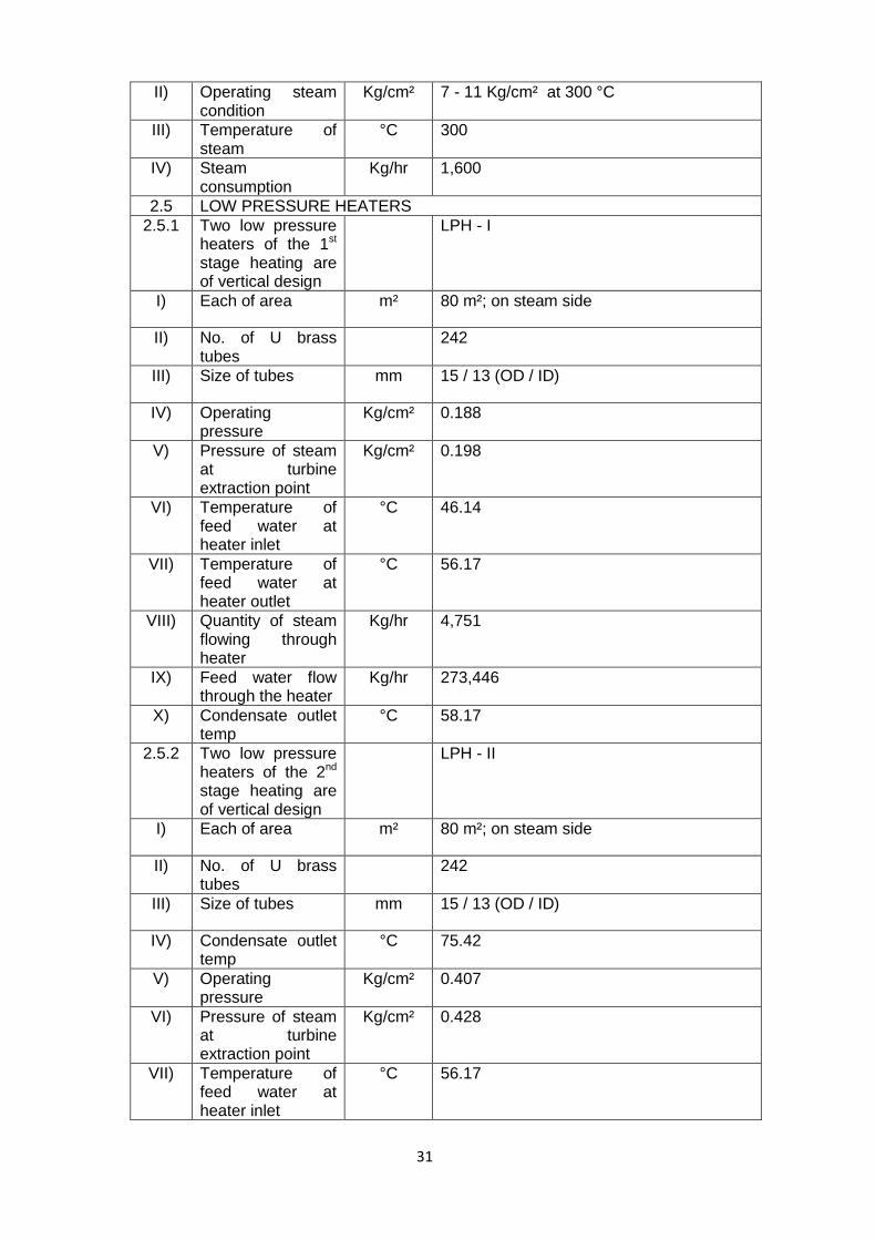
31
II) Operating steam condition
Kg/cm² 7 - 11 Kg/cm² at 300 °C
III) Temperature of steam
°C 300
IV) Steam consumption
Kg/hr 1,600
2.5 LOW PRESSURE HEATERS
2.5.1 Two low pressure heaters of the 1st stage heating are of vertical design
LPH - I
I) Each of area m² 80 m²; on steam side
II) No. of U brass tubes
242
III) Size of tubes mm 15 / 13 (OD / ID)
IV) Operating pressure
Kg/cm² 0.188
V) Pressure of steam at turbine extraction point
Kg/cm² 0.198
VI) Temperature of feed water at heater inlet
°C 46.14
VII) Temperature of feed water at heater outlet
°C 56.17
VIII) Quantity of steam flowing through heater
Kg/hr 4,751
IX) Feed water flow through the heater
Kg/hr 273,446
X) Condensate outlet temp
°C 58.17
2.5.2 Two low pressure heaters of the 2nd stage heating are of vertical design
LPH - II
I) Each of area m² 80 m²; on steam side
II) No. of U brass tubes
242
III) Size of tubes mm 15 / 13 (OD / ID)
IV) Condensate outlet temp
°C 75.42
V) Operating pressure
Kg/cm² 0.407
VI) Pressure of steam at turbine extraction point
Kg/cm² 0.428
VII) Temperature of feed water at heater inlet
°C 56.17
32
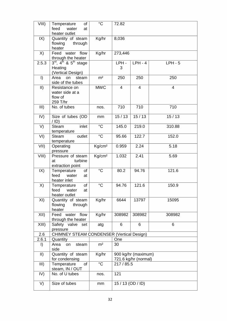
VIII) Temperature of feed water at heater outlet
°C 72.82
IX) Quantity of steam flowing through heater
Kg/hr 8,036
X) Feed water flow through the heater
Kg/hr 273,446
2.5.3 3rd, 4th & 5th stage Heating (Vertical Design)
LPH - 3
LPH - 4 LPH - 5
I) Area on steam side of the tubes
m² 250 250 250
II) Resistance on water side at a flow of 259 T/hr
MWC 4 4 4
III) No. of tubes nos. 710 710 710
IV) Size of tubes (OD / ID)
mm 15 / 13 15 / 13 15 / 13
V) Steam inlet temperature
°C 145.0 219.0 310.88
VI) Steam outlet temperature
°C 95.66 122.7 152.0
VII) Operating pressure
Kg/cm² 0.959 2.24 5.18
VIII) Pressure of steam at turbine extraction point
Kg/cm² 1.032 2.41 5.69
IX) Temperature of feed water at heater inlet
°C 80.2 94.76 121.6
X) Temperature of feed water at heater outlet
°C 94.76 121.6 150.9
XI) Quantity of steam flowing through heater
Kg/hr 6644 13797 15095
XII) Feed water flow through the heater
Kg/hr 308982 308982 308982
XIII) Safety valve set pressure
atg 6 6 6
2.6 CHIMNEY STEAM CONDENSER (Vertical Design)
2.6.1 Quantity One
I) Area on steam side
m² 30
II) Quantity of steam for condensing
Kg/hr 900 kg/hr (maximum) 721.6 kg/hr (normal)
III) Temperature of steam, IN / OUT
°C 217 / 85.5
IV) No. of U tubes nos. 121
V) Size of tubes mm 15 / 13 (OD / ID)

33
VI) Resistance on water side at a flow of 250 T/hr
MWC 5
VII) Operating pressure on steam side
ata 0.95
VIII) Operating pressure on water side
atg 20
2.6.2 Chimney steam exhaust fan (each 100%)
Two
I) Output m³/sec 0.33
II) Temperature of mixture
°C 150 (maximum)
III) Pressure of suction
MWC 0.250
IV) Fan drive motor rating
10 HP, 415V, 50 cycle, 3 phase
2.7 GLAND STEAM CONDENSER (Vertical Design)
I) Quantity One
II) Area m² 80
III) Quantity of steam for condensing
Kg/hr 3,800 kg/hr (maximum)
IV) No. of U tubes nos. 256
V) Size of tubes mm 15 / 13 (OD / ID)
VI) Test pressure on water side
atg 60
VII) Operating pressure on steam side
Kg/cm² 1.02 abs.
VIII) Inlet temperature of feed water
°C 73.57
IX) Outlet temperature of feed water
°C 78.57
X) Inlet steam temperature
°C 391.0
XI) Outlet steam temperature
°C 81.0
2.8 Condensate expander at the pressure level of 3rd stage heating
I) Quantity One
II) Safety valve setting pressure
atg 6
III) Test pressure with water (shell side)
atg 9
2.9 HIGH PRESSURE HEATERS (vertical design)
I) 7th & 8th stage Heating (Vertical Design)
HPH - I HPH - II

34
II) Area on steam side of tubes
m² 320 320
III) No. of spiral steel nos. 240 339
IV) Size of tubes mm 25 / 15 25 / 15
2.7 Resistance on water side at flow of 320 T/hr in spiral tubes
MWC 17 17
I) Design pressure on steam side
atg 20 40
II) Design pressure on water side
atg 240 240
III) operating pressure on steam
Kg/cm² 17.24 32.12
IV) Pressure of steam at turbine extraction point
Kg/cm² 19.12 35.85
V) De-superheating section surface area
m² 55 55
VI) Condensing section surface area
m² 190 290
VII) Feed water flow through the heater
Kg/hr 360,000 360,000
VIII) Temperature of feed water at heater inlet
°C 178.55 197.75
IX) Temperature of feed water at heater outlet
°C 197.75 2330.95
X) Quantity of steam flowing through heater
Kg/hr 11,133 28,459
XI) Temperature of condensate drain exit of heater
°C 204.05 236.55
XII) Drain flow entering the heater
Kg/hr 29,916 -
XIII) Drain flow leaving the heater
Kg/hr 33,315 29,916
2.10 DEAERTOR
I) Type Perforated tray type with external vent condenser
II) Design pressure i) Storage Tank and heater 12 kg/cm2 & full vaccum
ii) Vent condenser shell side 12kg/ cm2
& full vaccum water side 16 kg/cm2
III) Mean active storage capacity of tank 2/3 dia (normal level)
m³ 80

35
IV) Volume of D/A storage tank
m³ 120
V) Dissolved O2 contain in outgoing F.W
Less than 0.005 cc/litre
2.11 GENERATOR HYDROGEN SYSTEM
2.11.1 HYDROGEN SYSTEM
I) Hydrogen Gas cylinder
6 cylinders
II) No. per distributor 2 groups / 3 cylinder per group
III) Cylinder pressure atg 150
IV) Free volume of cylinder
m³ 6
V) Setting of safety valve at header
atg 5
VI) Pressure regulator for feeding to generator
atg 3.0 - 3.5
VII) Number of cylinders required for filling the generator to 2 atg pressure
At rest 28 cylinders (168 m³)
VIII) Number of cylinders for 5 days operation (max allowable leakage 24 m³/day)
20 cylinders
2.11.2 CARBON DIOXIDE GAS CYLINDER
I) Number per distributor
Per each of two groups
II) Cylinder pressure atg Around 65 atg
III) Free volume of cylinder
m³ 10 m³ (20 kg of CO2)
IV) Setting of safety valve on the header
atg 5
V) Pressure to be maintained inside the generator during scavenging
mmwc 150 - 200
VI) Number of cylinders stored for scavenging operation (at rest)
18 CO2 bottles (for scavenging 7 cylinders required)
2.11.3 HYDROGEN DRYERS
I) Number per unit Two

36
II) Drying media Silica gel
III) Drying temperature
°C 108 °C of silica gel
2.11.4 HYDROGEN COOLLERS
I) Number per unit 6
II) Type HC-WII-BS/cu. 6 (10x5-2-260)
III) Portion Horizontal
IV) Cooling medium Clarified water
V) Losses dissipated KW 1,500
VI) Coolled medium Hydrogen at 2 atg
VII) Flow of H2 through cooler
m³/sec 30
VIII) Flow of water through cooler
m³/hr 250
IX) Cooler water temperature
°C 34
X) Inlet cold H2 temperature (max)
°C 40
XI) Flow resistance (Hydrogen water side)
mmwc 12 - 4000
2.12 SEAL OIL SYSTEM
2.12.1 Seal oil pressure/ temperature
I) Hydrogen side pressure
atg 0.75 atg higher than H2 pressure
II) Air side pressure atg 0.55 atg higher than H2 pressure
III) Seal oil temp. at inlet to sealing rings
°C 25- 35
IV) Temperature of oil in vaccum tank
°C 40- 50
V) Working pressure of vaccum tank
(-) 0.85 to (-) 0.92
2.12.2 SEAL OIL COOLER
I) Number per unit 1+1=2
II) Type Shell & Tube, horizontal
III) Total cooling water flow
m³/hr 70
IV) Heat transfer area m² 24.2
V) Inlet oil temperature
°C 40- 50

37
VI) Output oil temperature
°C 25- 35
VII) Working pressure of oil
atg 4.5
2.12.3 SEAL OIL PUMPS Two
I) Main Seal oil pump motor
7 KW, 415V, 50 Hz, 700 RPM
II) Emergency seal oil pump
4.8 KW, 220V- DC
2.12.4 EQUALISING TANK
I) Number per unit One
II) Capacity up to normal level (including stilling chamber)
Litres 450
2.12.5 VACCUM PUMP One
I) Type of pump Gear pump
II) Pump motor rating 7 KW, 415V, 50 Hz
2.13 UNIT CONDENSATE FLOATING TANK/ HOTWELL
I) Capacity m³ 300
CIRCULATING WATER SYSTEM FOR CONDENSER COOLING
1 A Main Circulating Water Pump
I) Application Main CW Pump
II) No. Five (5) (for 2 units, 1 standby)
III) Pump type BHO 70, mixed flow, single stage forced cleaned water lubrication pump
IV) Capacity (each) m3 /hr 8575
V) Bowl head TDH M 26.18
VI) Speed RPM 594
VII) Rotation Clockwise when viewed from top
VIII) Shut off head 42-in design speed
IX) Starting torque delivery valve closed
KW 605
X) Maximum working pressure allowed
kg/cm2 2.85

38
XI) Motor HP KW 795 (BHEL)
B Main circulating water Sump levels
I) Sump bottom M 95.0 (EL)
II) Minimum available pump sub-mergence measured from bell mouth
mm 3740
III) Capacity m3 2000
IV) Minimum water level for pump in operation
99.50
V) Normal water level
M 100.0
VI) Max, water level M 100.3
C Quantity of Lube Water
Quantities of lube water for CW pump motor brg.
Lt/Min 30
2 CONDENSATE PUMP
I) Type 150 CJNV/6
II) No. No. 6(3 for each Unit)
III) Capacity T/hr 160
IV) Head mwc 270
V) Speed RPM 1489
VI) Minimum output of Elect. Motors
KW 195
I) Squirrel cage Inductance Motor Rated capacity
KW 225
3 CONDENSATE BOOSTER PUMP (Horizontal Multi Stage)
I) Type 100 CJH/7
II) No. Nos. 4(2 for each unit)
III) Capacity t/hr 65
IV) Delivery Head MWC 200
V) Speed rpm 1470

39
VI) Input KW 56
VII) Temperature of steam
°C 120
VIII) Squirrel cage Inductance Motor Rated capacity
KW 90 KW
4 BFP Technical Specification
I) Type
200KHI
II) No Nos 4 (2 for each Unit)
III) Delivery capacity lpm 8180
IV) Feed water temperature
°C 158
V) Head developed by pump
mlc 1960
VI) Speed RPM 4500
VII) Pressure at suction branch
ata 9
VIII) Quantity of water for warming up
t/hr 8
IX) Lubrication Forced
X) Consumption of cooling water
l/m 280
XI) Net weight of pump
KG 5850
XII) Arrangement 1+1
XIII) Pipe size (Suc/Disch.)
inch 10
XIV) Motor
XV) Make BHEL(HYD)
XVI) Type AM4000/6600
XVII Output KW 4000
XVIII Rated voltage KV 6.6
XIX Current Amps 421
XX Speed RPM 1484
5 CLARIFIED WATER PUMP
No. 3
I) CSD NO.& Make L-7153 Fairbanks Morse
II) Fig. & Size 7000-8M-8 STG
III) Capacity m3/hour 42
IV) TDH M 50

40
V) SPEED RPM 1460
VI) Motor Rating H.P 12.5
VII) Efficiency % 77
VIII) Bottom Clearance mm 152
6 FILTER BACK WASH PUMP
No. 3
I) CSD NO. JTC12GM WPIL
II) Fig. & Size KV-160
III) Capacity m3/hour 200
IV) Bowl Head mwc 15.19
V) SPEED RPM 1460
VI) Motor Rating KW 17.5
VII) Efficiency % 80
VIII) Surface Discharge Head
inch 12*8
7 BCW PUMPS Nos 7
I) CSD NO. L-7167 Fairbanks Morse
II) Fig. & Size 7000-15H-4 STG
III) Capacity m3/hour 480
IV) TDH M 60
V) SPEED RPM 1460
VI) Motor Rating H.P 160
VII) Efficiency % 82
VIII) Bottom Clearance mm 270
8 BCW DRAIN PUMPS
Nos 5
I) CSD NO. L-7175 Fairbanks Morse
II) Fig. & Size 7000-15H-2 STG
III) Capacity m3/hour 550
IV) TDH M 25
V) SPEED RPM 1460

41
VI) Motor Rating H.P 80
VII) Efficiency % 82.5
VIII) Bottom Clearance mm 270
9 RAW WATER PUMP
Nos 3
I) Sr. NO. 839587-89
II) Fig. & Size 6360W#14-2
III) Capacity m3/hour 1500
IV) TDH mwc 12
V) SPEED RPM 975
VI) Motor Rating H.P 90
VII) Efficiency % 85
VIII) Bottom Clearance mm 76
10 COLONY PORTABLE PUMPS
Nos 5
I) CSD NO. JTS-8B WPIL
II) Fig. & Size inch 22*6
III) Capacity m3/hour 70
IV) No. of stages 8
V) SPEED RPM 2900
VI) Motor Rating HP 75
VII) Efficiency % 69.5
VIII) Bowl Head M 180.10
11 SERVICE WATER PUMP
Nos 2
I) Sr. NO. 320031/32-75KSB
II) Fig. & Size MLC-KW 3.592/84
III) Capacity m3/hour 415V
IV) TDH M 60
V) SPEED RPM 1450
VI) Motor Rating H.P 95

42
12 INSTRUMENT AIR COMPRESSORS
04
I) Type Balanced opposite type
II) Model 2HA2T
III) Speed 710
IV) Discharge pressure
Kg/cm² 8.0
V) Air compressed cfm 320
VI) Volumetric efficiency
% 88.59
VII) Brake (H.P) HP 65.2
VIII) Lubrication
XI) Cylinder Teflon Rings
X) Bearings Forced feed by gear pump
XI) Rated Output HP 75
XII) Motor Speed RPM 1500
XIII) Driven V belt drive
13 SERVICE AIR COMPRESSORS
Nos. 03
I) Type Horizontal opposed type
II) Model 2HA2Ter
III) Speed RPM 710
IV) Discharge pressure
Kg/cm² 8.0
V) Air compressed cfm 500
VI) Volumetric efficiency
% 89.69
VII) Brake (H.P) HP 102
VIII) Lubrication
XI) Cylinder Teflon Rings
X) Bearings Forced feed by gear pump
XI) Rated Output HP 120
XII) Motor Speed RPM 1500
XIII) Driven V belt drive

43
14 DRIER 04 nos
I) Type Blower reactivated type
II) Capacity cfm 325
III) Inlet pressure Kg/cm² 07
IV) Inlet temp. °C 40
V) Cycle Time
VI) Absorption 6hours
VII) Heating 3 Hours
VIII) Cooling and idling 3 Hours
XI) Total Cycle time 12 Hours
14.1 Reactivation air Flow
14.1.1 Source Blower R
14.1.2 Net air flow from dryer CFM
325
Temperature required for reactivation
°C 180-200
14.2 HEATER
14.2.1 Heater Rating KW 18
14.3 Desicant Silica gel IS:3401
14.3.1 Type Silica gel
14.3.2 Number Nos 4
14.3.3 Expected life One year

44
2X110MW Stage-II Panipat Thermal Power Station
C & I SYSTEM
Control System Analog Type
Make Keltron/Controle Bailey
Model Keltron- 9020
Description
Operational Amplifiers are basic active elements of 9020 modules. These are third generation ampliefiers. They are supplied with one voltage only with high variation range from 3-33V.
Rack Size & Capacity 19" with 13 modules
Normal Working Voltage 28V(DC)
Max. Working Voltage 33V(DC)
High Voltage Protection 115V DC
220V AC for 5 sec
Plug-In Type Modules Used for Different Functions
Description of some of important modules
P+I Module (FE 7A41)
Proportional Action:2 to
500% Integral Action Time Constant:1.2 to 1875 sec
Setpoint :Internal
Derivative plus summing action module (FE 7B21)
Elaborates the deriative of a signal and the sum of singal and of its derivative to make a proportional and integral control loop with a separate derivative action in association with a P+I module
Memory transfer module (FE 7F91)
This module is associated with all remote control stations to memorize the control signal withourt drift. It transfers the various control modes when associated with a P+I module.
Control Stations (FE 7R11) Controls and displays - control mode auto/manual, controller output signal and position feedback signal.
Summing module (FE 7C12) Algebraically sums up three variables with adjustable gains
Function generator module (FE 7C21)
This module yields any non-linear function between the input and output signal by best fitting several segments with different slopes to the desired function.
Multiplier divider module ( FE 7C51)
Designed for adaptive control through adjustment of gains and time constants to the characteristics of the control system and corrections such as flow correction by pressure and temperature or level correction by pressure.
Square root extractor module ( FE 7C31)
Extacts the square root of a signal with an excellent conformative to the curve. A system that reduces the sensitivity when the input signal is near zero.

45
Dual Alarm module ( FE 7F31)
Controls opening or closing of a contact when the variable is beyond the adjustible setpoint, of a second contact when the variable is below a second adjustable setpoint, on each independent channel.
Tri-stable relay ( FE 7F21) Compares two signals. Opens or closes a contact when the difference between the signal is higher than the dead-band adjusted by a potentiometer.
Dual Voltage Monitor ( FE 7F12)
Opens or closes an external (alarm, logic sequential system, control loop) on either independent channel when the signal applied to the input reaches either a fixed and preset value, or value varying according to another signal. Hysteresis is adjustable.
Low Level Signal Converters ( FE 5A41)
Receive data from RTD thermocouples or any low level signal emitter and transform them into a high level DC signal
Isolation Converters ( FE 5E21) Isolates control loop I/P or O/P. It can receive or transmit non-standard signals and supply a 4-20 mA transmitter with 28 Volt
Switching Module (FE 7E72) Two Switches used for signals accessible on the front plate
Power Supply Specification for 9020 System (Redundant supply)
Make: Keltron Input:220V AC,50Hz, single phase Output Voltage:22-33V lockable, Output Current:50A for each unit
Control Drives
Description Double acting pneumatic control drives accurately operate and position regulating devices such as dampers , fan inlet vanes, butterfly valves etc.
Positioner This accurately positions a pneumatic actuator or diaphragm actuated valve on which it is mounted
Pneumatic Input Signal 0.2 to 1 bar
Pneumatic Supply Pressure 2.8, 3.5,7 bar
Electro-Pneumatic Converter
Description
The Electro-Pneumatic converter is a force-balance instrument which converts control signal of the control system into a proportional pneumatic signal to operate the final control element.
Input 4 to 20 mA
Output 0.2 to 1 Bar
Pressure 5 Bar

46
Air Consumption 180 Lph at NTP
Indicators
Make Masibus, Teletherm
Model (Masibus) 40005-SC, 40005-DC, 408, 506H
Model (Teletherm) Bargraph
Input(Masibus) Universal
Input(Teletherm) RTD,4-20mA/1-5V
Output(Masibus) Relays and 4 to 20 mA Isolated Retransmission Output
Recorders
Make Chino Corporation
Model KR3000, AL3000, AH3000 etc.
Input Universal
Turbovisory System
Make Phillips
Measurement Axial Shift of Turbine rotor at 3 points
Transducer used PR6424/00 and convertor CON010
Module Used DAM 010 used to convert transducer signal into 0-10VDC and 0/4-20mA
Measurement Differential Expansion of turbine at 3 no. of points
Transducer used PR6426/00 and convertor CON 091/16
Module Used DAM 010 used to convert transducer signal into 0-10VDC and 0/4-20mA
Measurement Shell expansion of turbine casing at 2 no. of points
Transducer used PR9350/02
Module Used MAI010 used to convert transducer signal into 0-10V DC and 0/4-20mA current output.
Measurement Vibration measurement
Rack Size
System Power Supply SPS 010(2 No.)
Relay Power Supply RPS 010 (1 No.)
Transducer used PR9266/02
47
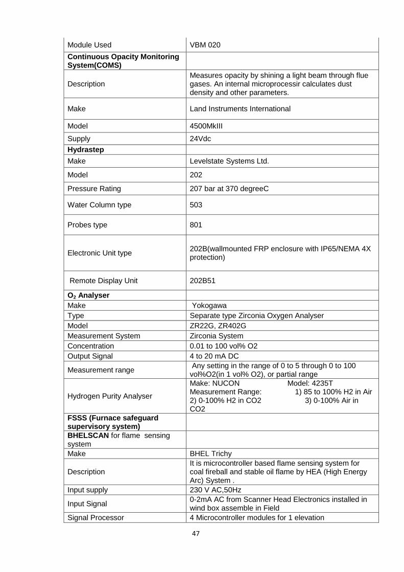
Module Used VBM 020
Continuous Opacity Monitoring System(COMS)
Description Measures opacity by shining a light beam through flue gases. An internal microprocessir calculates dust density and other parameters.
Make Land Instruments International
Model 4500MkIII
Supply 24Vdc
Hydrastep
Make Levelstate Systems Ltd.
Model 202
Pressure Rating 207 bar at 370 degreeC
Water Column type 503
Probes type 801
Electronic Unit type 202B(wallmounted FRP enclosure with IP65/NEMA 4X protection)
Remote Display Unit 202B51
O2 Analyser
Make Yokogawa
Type Separate type Zirconia Oxygen Analyser
Model ZR22G, ZR402G
Measurement System Zirconia System
Concentration 0.01 to 100 vol% O2
Output Signal 4 to 20 mA DC
Measurement range Any setting in the range of 0 to 5 through 0 to 100 vol%O2(in 1 vol% O2), or partial range
Hydrogen Purity Analyser
Make: NUCON Model: 4235T Measurement Range: 1) 85 to 100% H2 in Air 2) 0-100% H2 in CO2 3) 0-100% Air in CO2
FSSS (Furnace safeguard supervisory system)
BHELSCAN for flame sensing system
Make BHEL Trichy
Description It is microcontroller based flame sensing system for coal fireball and stable oil flame by HEA (High Energy Arc) System .
Input supply 230 V AC,50Hz
Input Signal 0-2mA AC from Scanner Head Electronics installed in wind box assemble in Field
Signal Processor 4 Microcontroller modules for 1 elevation

48
Display 2½ digit LED display
Programmable parametres Pull in, Pull out, Flicker frequency for Oil,Flicker frequency for coal
Communication Serial Interface by RS232C is available for DCS connectivity
Output of Flame sensing 2/4 output module(means when two or more than two coal flame in an elevation is detected)
Parameters setting 4x 8 bit DIP switches
2/4 Processor 2/4 Logic detection & Fault Alarm
Display Mode selection By push Button
Cooling Air requirement Air manifold pressure at scanner guie pipe must be 150mmwc
Power Supply module
It works in 110V AC or 230 V AC.It produces three DC outputs:- 1) +15 V Dc @ 0.75 Amps.max. 2) -15V DC @ 0.25 Amps. max. 3) +0.5 V DC @ 1.5 Amps. max.
Fuse and capacitors Rating Pico fuse rating 120mA,Capacitors 4700uF,16V
Flame Processor Module Standard Euro card suitable for 19" rack assy., DIP switches are present in this module for parameter settings
Rotary Pulse Generator
Description It is used to measure RPM of RC feeders
Operating Voltage 5V-15V DC
Material Stainless Steel Shaft 10/25mm,Other part Aluminium,Wheel Phosphor Bronze 0.2mm thick
Pulses per Revolution(PPR) 120
Operating Temp. 0°c to 50°c
Mounting Hub Mounting recommended with flexible coupling used for drive
Digital Tachometer
Make Systech 5508
Description It is used to digitally display the RPM measured by Rotary Pulse Generator.
Power Input 230 V AC 50 Hz,% Watt max.
No. of digits 4
Display 7 segment LED display
Time base accuracy 100 ppm,Quartz crystal,16,384 KHz
Description 96mm x 96mm x 200mm(depth)
Weight Not more than 2 Kgs
SADC System
Type BHEL Make
Power Supply ±15 V AC to ±24V AC
Power Supply Module in Contol room
Converts 110V AC to 24V AC,24 V Ac supply is used on desk to vary opening of SADC as per requirement, Sends 15 V DC to card No. CE691-11-271 Total No. of cards- 8 nos.(6 nos. for mill Ato F,1 no. for Auxillary Air,1 no. for HFO guns
Name of Cards in SADC Panel CE691-11-271- Analog Memory Card CE691-11-071-Light Duty Relay CE691-11-031-Relay Memory Card A/M
Vto I convertor Card no. CE691-11-271,This cards send current signal 4-20 mA to SADC at site .At site I/P coverter sends air

49
signal to SADC Cylinders
No. of SADC panels in Control Room
2 nos.
SADC Modules installed in Panels
Auxillary Air Elevation
1) CE691-11-460 2)CE691-11-490 3) CE691-11-040 4) CE691-11-151 5) CE691-13-091 6) CE691-22-071 7) CE691-13-102 8)CE691-6-200 9) CE691-22-260 10) CE691-39-040 11) CE691-13-220 12) CE691-13-121 13) CE691-22-031 14)CE691-43-271 15) CE691-22-071
Auxillary Oil Elevation
1) CE691-41-460 2)CE691-22-060 3) CE691-13-122 4) CE691-13-031 5) CE691-01-031 6) CE691-22-071 7) CE691-27-250 8)CE691-41-440 9) CE691-27-150 10) CE691-22-082
Coal Mills A to F Selector Cards 1) CE691-36-260 2)CE691-43-240 3) CE691-22-031
SADC Cylinder
SADC cylinder Make SMC Pneumatics and Hagan
Model No. 1-MBC63-125KY-RFP5744A
Description
Toatl NO. of Cylinders 52 per unit:- Detailed distribution -: 4 nos. Manual 24 nos. for Coal Mils A to F, 12 nos, for Auxillary Air, 12 nos. For HFO guns at 3 elevations
Air Cylinder Dia. 63mm.
Stroke size 125mm.
Ambient & Fluid temp. 110°c(Max.)
Supply pressure 0.3 - 0.7 Mpa
Signal pressure 0.02-0.1 Mpa
Tubing & fitting Copper & Brass
Mounting Single rear clevis

50
Ignitor System in field
High Energy Arc (HEA) Retractor Assy.)
Make Hindustan Ignition,Ambala Catt.
Total 4 nos./Unit
Air Cylinder Stroke upto 300mm.,Air pressure 5 to 7 kg/cm²
Operating Volatage for solenoid 110V AC
Limit Switches Total 2 nos. per assy.,10 Amps. rated Max. continuous
Operating Temp. 110°c(Max.)
Ignitior Tip
Operating Temp. 650°c(Max.)
Length 191 ± 3 mm
Diameter 15.9 ± 0.15 mm
Ignitior Excitor
Enclosure Construction Heavy-duty corrosion-resistant steel NEMA 4 rated
Input Volatage 110V AC
Input current 5 Amps.(RMS) Max.
Output Volatage 2500+ 150 V DC
Stored Energy 12 Joules Nom.
Spark Rate 4 per second Min.
Duty Cycle 15 minutes ON,30 minutes OFF
Operating Temp. minus 40°c to 75°c
Capacitor rating 10MFD/1500V
Panels in control room
FSSS unit panel 2 nos.
Mill panel Individual panel for each mill,total panels - 6 nos.
HFO gun Panels 2 panels for gun at each elevation,total no. of elevations 3 nos(AB,CD,EF) Total No. of panels-6 nos.
Timedelay Relays for Feeders EAPL ON delay timer 24 to 240 V AC Range 0.3sec to 30 min. MODEL- A1D1 X EAPL power OFF delay Timer 110V AC to 240 V AC Range 0.6sec to 60 sec.

51
Switchyard-I, PTPS-I, Unit #1 to 4
CIRCUIT BREAKERS
ABB Make SF6 CIRCUIT BREAKERS (GT-1, GT-2 & Bus Coupler)
i) Make : ABB
ii) CB Type : ELF SL 4-1
iii) Voltage : 245 kV
iv) Lightening Impulse Withstand Voltage : 1050 kVp
v) Normal Current : 2000A
vi) Short Circuit Breaking Current : 40 kA
vii) Short Time Withstand Current : 40kA for 3 sec.
viii) Line Charging Breaking Current : 125 A
ix) Operating Sequence : O-0.3s-CO-3min-CO
x) First Pole to Clear Factor : 1.3
xi) Gas Pressure SF6 (20o C) abs : 7.0 bar
xii) Air Pressure : 21.5 bar
xiii) Frequency : 50 Hz
xiv) Closing & Opening device Supply Voltage : 220 V DC
xv) Auxiliary Circuit Supply Voltage : 1-Ph 240V AC & 3-Ph
415 V AC
xvi) Mass (Appx.) : 4000kg
xvii) Operating Mechanism : Pneumatic (Opening
& Closing)
CGL Make SF6 CIRCUIT BREAKERS (GT-3, GT-4, Auto Tfr. 2)
i) Make : Crompton Greaves
Limited
ii) CB Type : 200-SFM-40A

52
iii) Voltage : 245 kV
iv) Lightening Impulse Withstand Voltage : 1050 kVp
v) Normal Current : 3150 A
vi) Short Circuit Breaking Current : 40 kA
vii) Rated Short Time Current : 40kA for 3 sec.
viii) Rated Short Circuit Making Current : 100 kA
ix) Line Charging Breaking Current : 125 A
x) Rated Break Time : 60 ms (3 cycles)
xi) Operating Sequence : O-0.3s-CO-3min-CO
xii) Rated Transient Recovery Voltage(TRV) : 364 kVp
xiii) Pole Discrepancy : 3.3ms
xiv) Gas Pressure SF6 (20o C) abs : 6.0 kg/cm2 at 20oC
xv) Operating Air Pressure : 16.5 kg/cm2
xvi) Frequency : 50 Hz
xvii) Closing & Opening device Supply Voltage : 220 V DC
xviii) Auxiliary Circuit Supply Voltage : 1-Ph 240V AC & 3-Ph
415 V AC
xix) Mass (Appx.) : 3900 kg
xx) SF6 Gas Weight : 21 kg
xxi) Operating Mechanism : Spring Closing,
Pneumatic Opening
xxii) Opening Time : 30 ms
xxiii) Closing Time : 100 ms
xxiv) Applicable Standard : IEC-62271-100
TELK Make SF6 CIRCUIT BREAKERS (ST-2, Sewah Ckt-4, Auto Tfr.-1)
i) Make : Transformers And Electricals Kerela
Limited (TELK)
ii) CB Type : OFPI-200-31L-PAR
iii) Voltage : 245 kV
iv) Lightening Impulse Withstand Voltage : 1050 kVp
v) Normal Current : 2000 A

53
vi) Rated Breaking Capacity : 31.5 kA for 1 sec
vii) Rated Short Circuit Making Current : 80 kA
viii) Rated Break Time : 50 ms
ix) Rated Make Time : 160 ms
x) Operating Sequence : O-0.3s-CO-3min-CO
xi) No. of Breaks Per Pole : 1
xii) Rated Gas Pressure SF6 : 6.0 kg/cm2 xiii)
xiii) Rated Air Pressure : 16.0 kg/cm2
xiv) Compressed Air System : Unit Compressor;
5HP; 260 lpm
xv) Frequency : 50 Hz
xvi) Closing & Opening device Supply Voltage : 220 V DC
xvii) Auxiliary Circuit Supply Voltage : 1-Ph 240V AC & 3-Ph
415 V AC
xviii) Mass (Appx.) : 5600 kg
xix) SF6 Gas Weight : 25 kg
xx) Operating Mechanism : Spring Closing,
Pneumatic
Opening
HBB Make Air Blast Circuit Breakers ( ST-1; Sewah Ckt 1,2 &3; Sonepat 1 &2)
i) Make : Hindustan Brown Boveri(HBB)
ii) CB Type : DLF 245 nc2
iii) Voltage : 245 kV
iv) U Impulse 1.2/50µs : 1050 kVp
v) Normal Current : 2000 A
vi) I Breaking : Sym 31.5 kA

54
vii) I Short Time : 55kA for 3 sec
viii) Voltage for Trip Coil : 220V DC
ix) Voltage for Close Coil : 220V DC
x) Operating Sequence : O-0.3s-CO-3min-CO
xi) Operating Pressure : 27-31 kg/cm2
xiii) Mass 1-Ø : 1630kg
xiii) Reference Standard : IEC-56
TMG make 220kV ISOLATORS (Centre Break)
i) Make :TMG ii) Type :SDRE-9 iii) Rated Voltage ,KV :220 iv) Rated Current ,Amp :1250 v) Operation Mechanism :Penumatic vi) Control Voltage DC,Volts :220 vii) Number of pole : 3 viii) Whether all three poles ganged : YES, Mechanically Ganged
S&S make 220kV ISOLATORS (Centre Break)
i) Make : S&S ii) Type : RC 300 iii) Rated Voltage : 220 kV iv) Rated Current : 1250 A v) Operation Mechanism : Penumatic vi) Control Voltage DC,Volts : 220 vii) Number of pole : 3
COMPRESSORS for ABCBs
i) MAKE : INGERSOLL RAND ii) TYPE : 30 (Compact 3-Stage Reciprocating
Compressor) iii) MODEL : 15-T2 iv) Pressure : 21.1kg/cm2 to 70.3kg/cm2 v) Air delivery : 135m3 /min to 886m3 /min
Motor for Compressor i) Make : ABB ii) Duty : S1 iii) Type : Sq.Cage Induction motor iv) Efficiency : 89% v) Capacity :15 Kw vi) HP : 20 vii) No of Phase : 3 viii) Rated Voltage : 415 ix) Running current : 27 Amp

55
x) Frequency : 50 Hz xi) RPM : 1455
14.3 CURRENT TRANSFORMERS
14.3.1 Current Transformers for Generator Transformer Bay (Metering &
Protection)
i) Make : BHEL/HBB
ii) Applicable Standard : IS 2705 (I to IV)
iii) Type /installation : Oil Immersed, Dead
Tank, Outdoor
installation
iv) Phase : 1
v) Frequency : 50
vi) Insulation Level
Highest System Voltage : 245 kVrms
1 min. dry & wet Power Frequency: 460 kVrms withstand Voltage
1.2/50 micro sec. Lightening impulse : 1050 kVp withstand Voltage
vii) Short Time Current Rating : 26 kA for 3 Sec (HBB
make)
40kA for 1
sec (Others)
No. of cores (06) Core-I
(Metering)
Core-II
(Over
Current
& LBB)
Core-
III
(R. E
.F)
Core-IV
(Bus Bar
Prot.)
Core-V
(Bus Bar
Prot.)
Core-VI
(Gen.
Overall
Differential)
Primary Current 1200-800-
400
1200-
800-400
1200-
800-
400
1200-800-
400
1200-800-
400
1200-800-
400
Secondary
Current
1-1-1 amp 1-1-1
amp
1-1-1
amp
1-1-1 amp 1-1-1 amp 1-1-1 amp
Accuracy Class 0.2 5P20 PS PS PS PS
Rated Burden 45 VA 30 VA NA NA NA NA
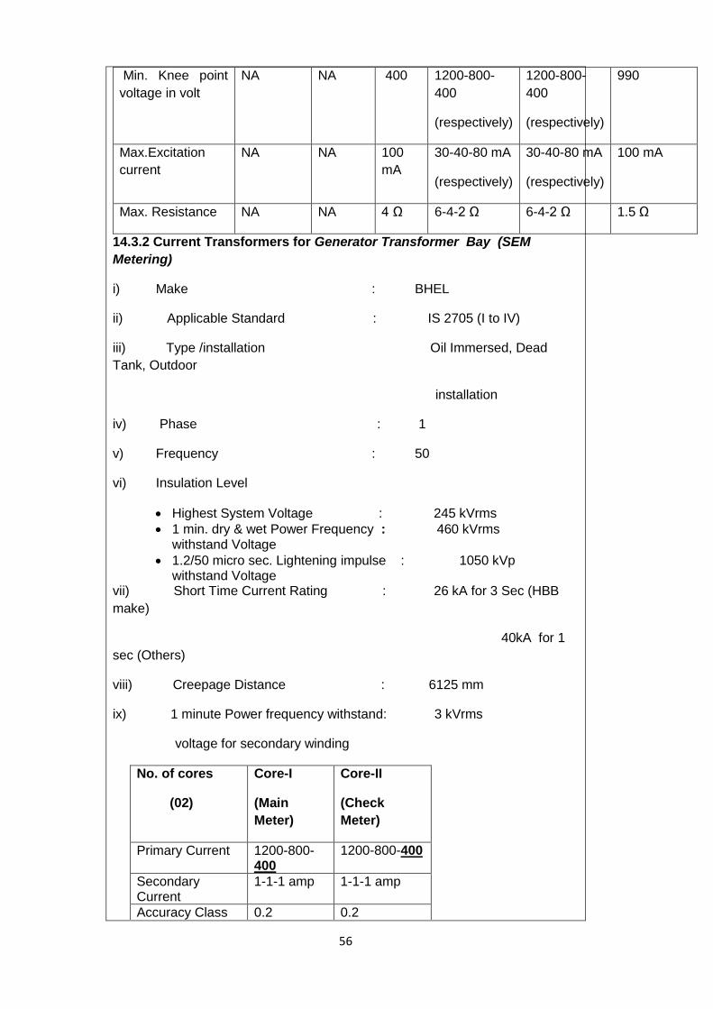
56
Min. Knee point
voltage in volt
NA NA 400 1200-800-
400
(respectively)
1200-800-
400
(respectively)
990
Max.Excitation
current
NA NA 100
mA
30-40-80 mA
(respectively)
30-40-80 mA
(respectively)
100 mA
Max. Resistance NA NA 4 Ω 6-4-2 Ω 6-4-2 Ω 1.5 Ω
14.3.2 Current Transformers for Generator Transformer Bay (SEM
Metering)
i) Make : BHEL
ii) Applicable Standard : IS 2705 (I to IV)
iii) Type /installation Oil Immersed, Dead
Tank, Outdoor
installation
iv) Phase : 1
v) Frequency : 50
vi) Insulation Level
Highest System Voltage : 245 kVrms
1 min. dry & wet Power Frequency : 460 kVrms withstand Voltage
1.2/50 micro sec. Lightening impulse : 1050 kVp withstand Voltage
vii) Short Time Current Rating : 26 kA for 3 Sec (HBB
make)
40kA for 1
sec (Others)
viii) Creepage Distance : 6125 mm
ix) 1 minute Power frequency withstand: 3 kVrms
voltage for secondary winding
No. of cores
(02)
Core-I
(Main
Meter)
Core-II
(Check
Meter)
Primary Current 1200-800-400
1200-800-400
Secondary Current
1-1-1 amp 1-1-1 amp
Accuracy Class 0.2 0.2
57
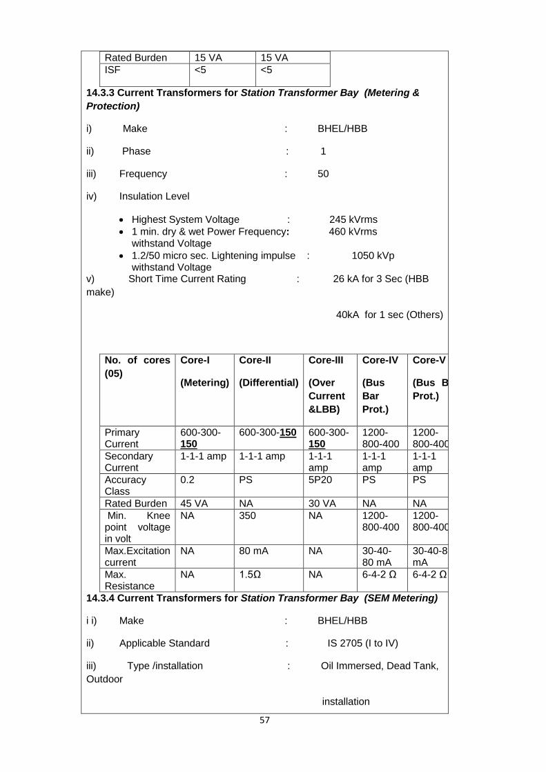
Rated Burden 15 VA 15 VA
ISF <5 <5
14.3.3 Current Transformers for Station Transformer Bay (Metering &
Protection)
i) Make : BHEL/HBB
ii) Phase : 1
iii) Frequency : 50
iv) Insulation Level
Highest System Voltage : 245 kVrms
1 min. dry & wet Power Frequency: 460 kVrms withstand Voltage
1.2/50 micro sec. Lightening impulse : 1050 kVp withstand Voltage
v) Short Time Current Rating : 26 kA for 3 Sec (HBB
make)
40kA for 1 sec (Others)
No. of cores
(05)
Core-I
(Metering)
Core-II
(Differential)
Core-III
(Over
Current
&LBB)
Core-IV
(Bus
Bar
Prot.)
Core-V
(Bus Bar
Prot.)
Primary Current
600-300-150
600-300-150 600-300-150
1200-800-400
1200-800-400
Secondary Current
1-1-1 amp 1-1-1 amp 1-1-1 amp
1-1-1 amp
1-1-1 amp
Accuracy Class
0.2 PS 5P20 PS PS
Rated Burden 45 VA NA 30 VA NA NA
Min. Knee point voltage in volt
NA 350 NA 1200-800-400
1200-800-400
Max.Excitation current
NA 80 mA NA 30-40-80 mA
30-40-80 mA
Max. Resistance
NA 1.5Ω NA 6-4-2 Ω 6-4-2 Ω
14.3.4 Current Transformers for Station Transformer Bay (SEM Metering)
i i) Make : BHEL/HBB
ii) Applicable Standard : IS 2705 (I to IV)
iii) Type /installation : Oil Immersed, Dead Tank,
Outdoor
installation

58
iv) Phase : 1
v) Frequency : 50
vi) Insulation Level
Highest System Voltage : 245 kVrms
1 min. dry & wet Power Frequency: 460 kVrms withstand Voltage
1.2/50 micro sec. Lightening impulse : 1050 kVp withstand Voltage
vii) Short Time Current Rating : 26 kA for 3 Sec (HBB
make)
40kA for 1
sec (Others)
viii) Creepage Distance : 6125 mm
ix) 1 minute Power frequency withstand : 3 kVrms
voltage for secondary winding
No. of cores
(02)
Core-I
(Main
Meter)
Core-II
(Check
Meter)
Primary Current 600-300-150
600-300-150
Secondary Current
1-1-1 amp 1-1-1 amp
Accuracy Class 0.2 0.2
Rated Burden 15 VA 15 VA
ISF ** <5 <5
**ISF: Instrument Security Factor.
14.3.5 Current Transformers for Outgoing Feeder Bay (Metering &
Protection)
i) Make : BHEL/SCT/HBB/Heptacare
ii) Phase : 1
iii) Frequency : 50
iv) Insulation Level
Highest System Voltage : 245 kVrms
1 min. dry & wet Power Frequency : 460 kVrms withstand Voltage
1.2/50 micro sec. Lightening impulse : 1050 kVp withstand Voltage
v) Short Time Current Rating : 26 kA for 3 Sec (HBB
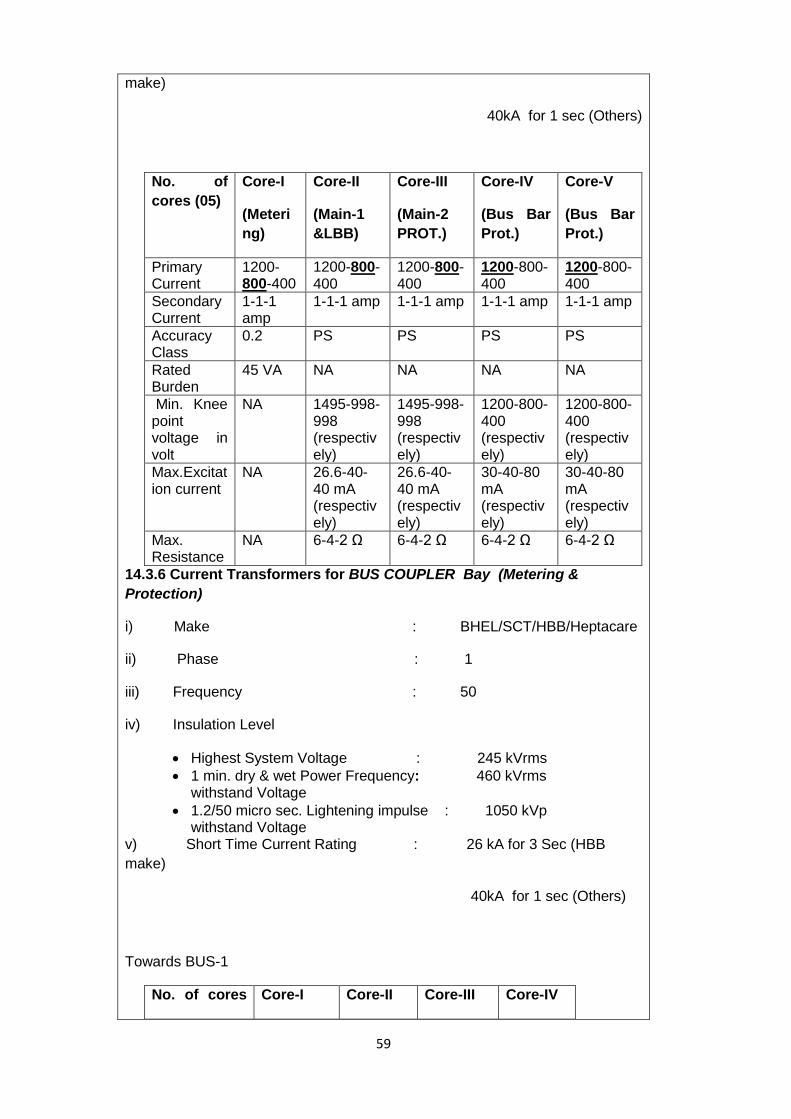
59
make)
40kA for 1 sec (Others)
No. of
cores (05)
Core-I
(Meteri
ng)
Core-II
(Main-1
&LBB)
Core-III
(Main-2
PROT.)
Core-IV
(Bus Bar
Prot.)
Core-V
(Bus Bar
Prot.)
Primary Current
1200-800-400
1200-800-400
1200-800-400
1200-800-400
1200-800-400
Secondary Current
1-1-1 amp
1-1-1 amp 1-1-1 amp 1-1-1 amp 1-1-1 amp
Accuracy Class
0.2 PS PS PS PS
Rated Burden
45 VA NA NA NA NA
Min. Knee point voltage in volt
NA 1495-998-998 (respectively)
1495-998-998 (respectively)
1200-800-400 (respectively)
1200-800-400 (respectively)
Max.Excitation current
NA 26.6-40-40 mA (respectively)
26.6-40-40 mA (respectively)
30-40-80 mA (respectively)
30-40-80 mA (respectively)
Max. Resistance
NA 6-4-2 Ω 6-4-2 Ω 6-4-2 Ω 6-4-2 Ω
14.3.6 Current Transformers for BUS COUPLER Bay (Metering &
Protection)
i) Make : BHEL/SCT/HBB/Heptacare
ii) Phase : 1
iii) Frequency : 50
iv) Insulation Level
Highest System Voltage : 245 kVrms
1 min. dry & wet Power Frequency: 460 kVrms withstand Voltage
1.2/50 micro sec. Lightening impulse : 1050 kVp withstand Voltage
v) Short Time Current Rating : 26 kA for 3 Sec (HBB
make)
40kA for 1 sec (Others)
Towards BUS-1
No. of cores Core-I Core-II Core-III Core-IV

60
(04) (Metering) (LBB) (Over
Current)
(Bus Bar
Prot.)
Primary
Current
1200-800-
400
1200-
800-400
1200-800-
400
1200-
800-400
Secondary
Current
1-1-1 amp 1-1-1
amp
1-1-1 amp 1-1-1
amp
Accuracy
Class
0.2 5P20 5P20 PS
Rated Burden 45 VA 30 VA 30 VA NA
Min. Knee
point voltage
in volt
NA NA NA 1200-
800-400
Max.Excitation
current
NA NA NA 30-40-80
mA
Max.
Resistance
NA NA NA 6-4-2 Ω
Towards BUS-2
No. of
cores (02)
Core-I
(Spare)
Core-II
(Bus Bar
Protn.)
Primary
Current
1200-800-
400
1200-800-
400
Secondary
Current
1-1-1 amp 1-1-1 amp
Class 5P20 PS
Rated
Burden
30 VA ----
Min. Knee
point
voltage in
volt
------- 800 V
Max.
Resistance
------- 15 Ohm

61
14.3.7 Potential Transformers for SEM Metering
i) Make : BHEL/SCT
ii) Applicable Standard : IS 3156 (I to III)
iii) Type /installation : Oil Immersed, Outdoor
installation
iv) Phase : 1
v) Frequency : 50
vi) Voltage Ratio : 240kV/ 120V / 120V √3 / √3 / √3 vii) Insulation Level
Highest System Voltage : 245 kVrms
1 min. dry & wet Power Frequency : 460 kVrms withstand Voltage
1.2/50 micro sec. Lightening impulse : 1050 kVp withstand Voltage
viii) Rated Voltage Factor : 1.2 continuous & 1.5
for 30 seconds
ix) Creepage Distance : 6125 mm
x) 1 minute Power frequency withstand : 3 kVrms
voltage for secondary winding
No. of cores (02) Core-I
(Main
Meter)
Core-II
(Check
Meter)
Primary Voltage 240 kV/√3 240 kV/√3
Secondary Volt 120 V/√3 120 V/√3
Accuracy Class 0.2 0.2
Output Burden 100 VA 100 VA
14.3.8 Potential Transformers for (Metering & Protection)
i) Make : BHEL
ii) Type : ON
iii) Phase : 1
iv) Frequency : 50
v) Line Volts : 220000
vi) Primary Volts : 240000/√3

62
vii) Secondary Volts : 120/√3
viii) Insulation Level
Highest System Voltage : 245 kVrms
1 min. dry & wet Power Frequency : 460 kVrms withstand Voltage
1.2/50 micro sec. Lightening impulse : 1050 kVp withstand Voltage
ix) Rated Voltage Factor/Time : 1.5 /30 seconds
x) VA Per Phase : 500
xi) Class : 1.0
xii) Primary Neutral : Earthed
Xiii) Standard : IS:3156
14.3.9 CGL Make Capacitor Voltage Transformer (CVT)- On outgoing Ckt.
i. Make : Crompton Greaves ii. Type : CVE:245/1050/50 iii. Standard : IEC:186(87); IEC:358(90)
IS:3156(92); IS9348(98) iv. Highest System Voltage : 245 kV v. Equi. Capacitance : 8800(+10% to-5%) pf vi. Frequency : 50Hz vii. Prim. Capacitance : 9470pf nominal viii. Sec. Capacitance : 124475pf nominal ix. Capacitor Oil : 90±5% kg x. Insulation Level : 460KV/1050kVp xi. Voltage factor : 1.2 CONT. & 1.5 for 30sec xii. Intermediate Voltage : 10kV xiii. Total Simult. Burden/Class : 150VA/1.0 xiv. Voltage Ratio & other details :
Description Primary Secondary
CORE-I CORE-2
A-NHF 1a-1n 2a-2n
Volts 220000/√3 110/√3 110/√3
VA ----- 100 50
Class ------ 1.0 & 3P 3P
14.3.10 Alstom Make Capacitor Voltage Transformer (CVT) - On outgoing
Ckt.
i. Make : Alstom T & D India Ltd. ii. Type : CVCEC/245/1050
iii. Standard : IEC:186 iv. Rated Voltage : A-N,220/√3kV v. Highest System Voltage : A-N,245/√3kV

63
vi. HF Capacitance : 5000(+10% to-5%) pf vii. Frequency : 50Hz
viii. Prim. Capacitance C 1 : 5238 pf (+10% to -5%) ix. Sec. Capacitance C2 : 110000pf (+10% to -5%) x. Weight : 675 kg
xi. Insulation Level : 460KV/1050kVp xii. Voltage factor : 1.2 CONT./1.5-30sec
xiii. Nom. Intermediate Voltage : 10/√3kV xiv. Total Simult. Burden/Class : 90VA xv. Voltage Ratio : 240000V / 120V / 120V
√3 / √3 / √3
CORE-I CORE-2
Winding 1a-1n 2a-2n
Volts 120/√3 120/√3
VA 45 45
Class 0.5 3P
PANIPAT TERMAL POWER STATION(UNIT-1 to 4)
(220kV Switchyard-1)
GENERATOR TRANSFORMER (4 nos. for Unit I & 4 nos. for PTPS-1) i) Make : BHEL ii) Rated Output : 140/98/70 MVA iii) Type of Cooling : OFB/OB/ON (OFAF/ONAF/ONAN) iv) Rated Voltage- HV/LV : 240/11 kV v) Rated Current HV/LV : 336.79/7348.3 A(at 140VA) vi) Phase : 3 vii) Frequency : 50 viii) Vector Group Yd1 ix) Temperature rise of OIL : 45°C above 50°C ambient x) Temperature Rise of Winding : 60/55°C above 50°C ambient xi) Tappings : OLTC 20 Steps (Make BHEL)
+5% to -10% (@1.25%) xii) OLTC Type : MA7 (BHEL) xiii) Impedance (principal Tap) : 12.50%

64
xiv) No. of cooling Units : 06 no. Fans & 2 no. Pumps xv) No. of standby pump & Fan in cooler : 02 no. Fans &2 no. Pumps xvi) Approximate Qty of OIL : 48,400 Litre xvii) Insulation Level HV : 900 kVp
Insulation Level LV : 75 kVp Insulation Class HV Neutral : 38 kVrms
xviii) Weight Total Weight : 200,000 kg Core & Coil : 101,130 kg Oil : 41400 kg (48400 Liters)
xix) Air Circulation : 6 X 365 m3/min.
PANIPAT TERMAL POWER STATION(UNIT-1 to 4)
(220kV Switchyard-1)
STATION TRANSFORMER (For Unit I&2-1 No, Unit 3 &4-1 No.) i) Make : BHEL ii) Rated Output : 28/25 MVA iii) Type of Cooling : ON/OB (ONAF/ONAN) iv) Rated Voltage- HV/LV/SV : 240/11/7 kV v) Rated Current HV/LV /SV : 73.5/2307/490.7 A (at 28MVA) vi) Number of winding per Phase : 3 (3 phases) vii) Frequency : 50 Hz viii) Vector Group (HV/LV) : Yy0 (HV/SV) : Yd1 ix) Temperature rise of OIL : 45°C x) Temperature Rise of Winding : 55˚C over ambient of 50˚C xi) Tappings : OLTC (Make BHEL)
+10% to -10%(@
1.25%)
xii) Impendance (Principal Tap) : 12.0%AT Base28MVA) xiii) No. & Capacity of cooling Units : 02 no. Fan. xiv) No. of standby Fan in cooler : 1 No. xv) Type of Tank Construction :

65
Conventional Type xvi) Approximate Qty of OIL : 35510 Litre xvii) Insulation Level HV : 900 kVp Insulation Level LV : 60 KVp Insulation Class HV Neutral : 38 kV RMS Insulation Class LV Neutral : 22 kV RMS Insulation Class SV : 28kV RMS xviii) Weight
Total Weight : 106040 kg Core & Coil : 43710 kg Oil : 30050 kg (35510 Liters)
xix) Air Circulation : 2 X 365 m3/min.
PANIPAT TERMAL POWER STATION(UNIT-1 to 4)
(220kV Switchyard-1)
UNIT AUX. TRANSFORMER (4 nos.- One for each unit) i) Make : BHEL
ii) Rated Output : 15 MVA
iii) Type of Cooling : ON
iv) Rated Voltage- HV/LV : 11/7KV
v) Rated Current HV/LV :
787.3/1237.2A
vi) Number of winding per Phase 2 (3 phases)
vii) Frequency : 50 Hz
viii) Vector Group : Dyn11
ix) Temperature rise of OIL : 45°C above
ambient
temp.50˚C
x) Temperature Rise of Winding : 55°C above
ambient
temp.50˚C

66
xi) Tappings : OFF-CIRCUIT Tap changer
+5% to -5% (@2.5%)
xii) Impendance (principal Tap) : 7.0% + IS
tol.
xiii) Type of Tank Construction : Conventional
Type
xiv) Approximate Qty of OIL : 9250
Litre (Approx.)
xv) Insulation Level HV : 75 KVp
Insulation Level LV : 60KVp
xvi) Weight Total Weight : 35730Kg (Approx.) Core & Coil : 16320Kg(Approx.)
Oil :
7830Kg(Approx.)
PANIPAT TERMAL POWER STATION(UNIT-1 to 4)
(220kV Switchyard-1)
SERVICE TRANSFORMERS (Total-29 no.) i) Make: NGEF ,KAVIKA,GEC
ii) Rated Output : 1600KVA, 6.6/0.433 KV 1000KVA,6.6/.433KV 2000KVA, 11/6.6KV
iii) Type of Cooling : AN (OIL FILLED)
iv) Rated Voltage- HV/LV : 6.6 kV/0.433 kV
Or 11kv/6.6 kV
v) Rated Current HV/LV 1600 kVA-6.6/.433KV-140/2133A 1000 kVA-6.6/.433kv-87.5/1333 A 2000 kVA-11/6.6KV-104.98/174.96A vi) Frequency : 50 Hz
vii) Vector Group : Dyn11

67
viii) Temp rise in winding : 55˚C over ambient of 50 ˚C
ix) Tap Changer : OFF-Circuit
+/- 5%, steps of 2.5%
x) Impendance : 8.0 %(Approx) (1000 kVA) 8.0 % (Approx) (1600 kVA) 7.32% (Approx.)(2000 kVA)
xi) Weight : 1000 kVA – 4550 kg, 6.6/.433kv
1600 kVA – 5960 kg, 6.6/.433kv 2000 kVA-6111kg, 11/.433kv
xii) Application : Unit Service -1000KVA (4
no.)6.6/.433KV
Station Service -1600KVA (4
no.)-6.6/.433KV
Colony Service -2000KVA (1
no.)11/6.6 KV
Coal Handling -1600KVA (2
no.)-6.6/.433KV
Ash Handling-1000KVA (2 no.-Unit-
1&2)-6.6/.433KV
Ash Handling-1600KVA (1 no.-Unit-
3&4)-6.6/.433KV
Raw Water-1000KVA (1 no.)-
6.6/.433KV
Misc. Pump House-1000KVA (1
no.)-6.6/.433KV
Decanting -1000KVA (2
no.)-6.6/.433KV
ESP – 1600 kVA
(6no).-6.6/.433KV
DM Plant -1600KVA (1
no.)-6.6/.433KV
CW Pmp -1600
kVA(2nos)6.6/.433KV
Clarifier -1600KVA(1 no)-
6.6/.433KV
68
Clarifier -1000KVA(1no)-
6.6/.433KV
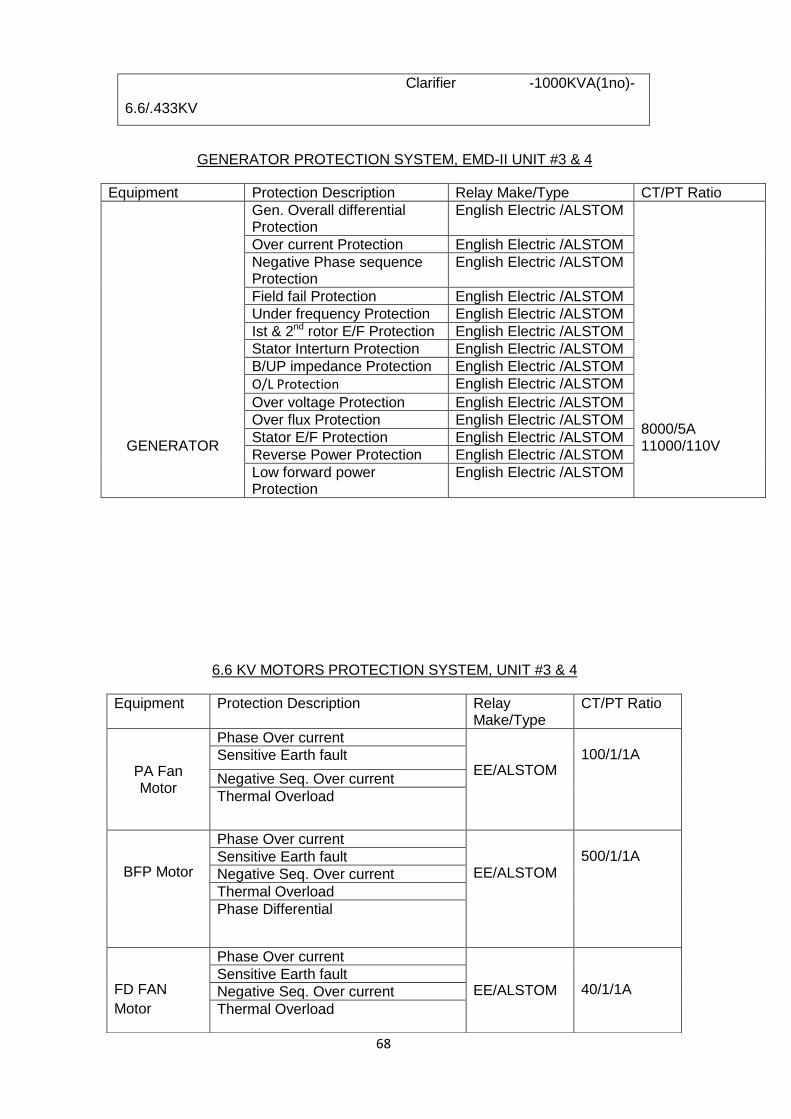
GENERATOR PROTECTION SYSTEM, EMD-II UNIT #3 & 4
Equipment Protection Description Relay Make/Type CT/PT Ratio
GENERATOR
Gen. Overall differential Protection
English Electric /ALSTOM 8000/5A 11000/110V
Over current Protection English Electric /ALSTOM
Negative Phase sequence Protection
English Electric /ALSTOM
Field fail Protection English Electric /ALSTOM
Under frequency Protection English Electric /ALSTOM
Ist & 2nd rotor E/F Protection English Electric /ALSTOM
Stator Interturn Protection English Electric /ALSTOM
B/UP impedance Protection English Electric /ALSTOM
O/L Protection English Electric /ALSTOM
Over voltage Protection English Electric /ALSTOM
Over flux Protection English Electric /ALSTOM
Stator E/F Protection English Electric /ALSTOM
Reverse Power Protection English Electric /ALSTOM
Low forward power Protection
English Electric /ALSTOM
6.6 KV MOTORS PROTECTION SYSTEM, UNIT #3 & 4
Equipment Protection Description Relay Make/Type
CT/PT Ratio
PA Fan Motor
Phase Over current
EE/ALSTOM
100/1/1A
Sensitive Earth fault
Negative Seq. Over current
Thermal Overload
BFP Motor
Phase Over current EE/ALSTOM
500/1/1A
Sensitive Earth fault
Negative Seq. Over current
Thermal Overload
Phase Differential
FD FAN
Motor
Phase Over current EE/ALSTOM
40/1/1A Sensitive Earth fault
Negative Seq. Over current
Thermal Overload
69
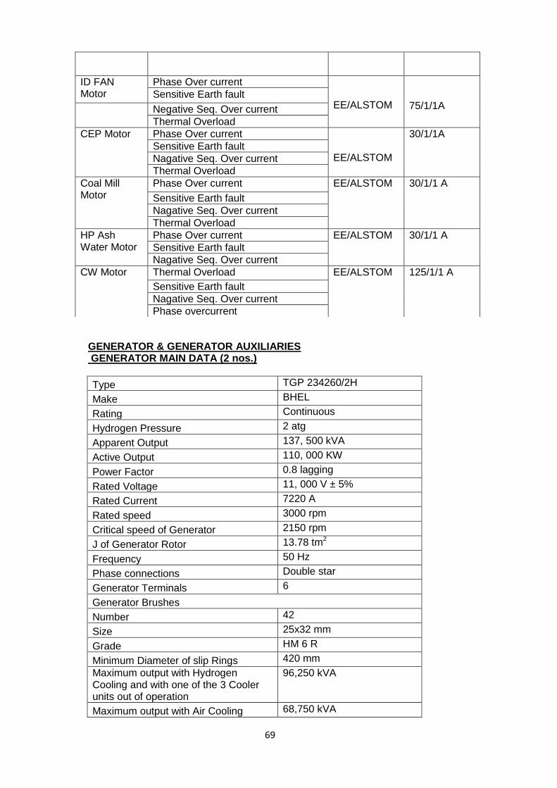
GENERATOR & GENERATOR AUXILIARIES GENERATOR MAIN DATA (2 nos.)
Type TGP 234260/2H
Make BHEL
Rating Continuous
Hydrogen Pressure 2 atg
Apparent Output 137, 500 kVA
Active Output 110, 000 KW
Power Factor 0.8 lagging
Rated Voltage 11, 000 V ± 5%
Rated Current 7220 A
Rated speed 3000 rpm
Critical speed of Generator 2150 rpm
J of Generator Rotor 13.78 tm2
Frequency 50 Hz
Phase connections Double star
Generator Terminals 6
Generator Brushes
Number 42
Size 25x32 mm
Grade HM 6 R
Minimum Diameter of slip Rings 420 mm
Maximum output with Hydrogen Cooling and with one of the 3 Cooler units out of operation
96,250 kVA
Maximum output with Air Cooling 68,750 kVA
ID FAN Motor
Phase Over current
EE/ALSTOM
75/1/1A
Sensitive Earth fault
Negative Seq. Over current
Thermal Overload
CEP Motor Phase Over current EE/ALSTOM
30/1/1A
Sensitive Earth fault
Nagative Seq. Over current
Thermal Overload
Coal Mill Motor
Phase Over current EE/ALSTOM 30/1/1 A
Sensitive Earth fault
Nagative Seq. Over current
Thermal Overload
HP Ash Water Motor
Phase Over current EE/ALSTOM 30/1/1 A
Sensitive Earth fault
Nagative Seq. Over current
CW Motor Thermal Overload EE/ALSTOM 125/1/1 A
Sensitive Earth fault
Nagative Seq. Over current
Phase overcurrent

70
Maximum inductive output at the rated Voltage and Zero Power factor lagging
110,000 kVAr
Maximum capacitive output at the rated Voltage and Zero Power factor lagging
50,000 kVAr
Maximum amplitude of the sudden short circuit current including DC component
10.7 x In peak
Inherent voltage-regulation 33.5%
Short Circuit ratio 0.59
The efficiencies of the Turbo-generator including losses in the excitation system and bearings at the following loadings are as given below (at Hydrogen Pressure: 2 atg)
% Load 100 75 50 25
at 0.8 p.f. lagging 98.32 98.29 98.00 96.84
at U.P.F 98.8 98.76 98.52 97.56
Reactances (Informative)
Direct axis unsaturated sychronous reactance
Xd 198%
Direct axis transient reactance X'd 24.7%
Direct axis subtransient reactance X''d 16.8%
Negative sequence reactance X2 16.8%
Zero sequence reactance X0 8.3%
Time Constants (Informative)
Direct axis transient open-circuit time constant
T'd0 5.51 sec.
Direct axis transient short-circuit time constant T'd 0.687 sec.
Direct axis sub- transient short-circuit time constant T''d 0.03 sec.
Armature short-circuit time constant
Ta 0.339 sec.
HYDROGEN COOLERS:
Type HC-W II-Bs/Cu 6 (10x5-2-260)
Number of Cooler elements 6
Cooling Medium Water of a quality accepted byboth BHEL, Hyderabad and the Customer.
Cooled Medium Hydrogen at 2 atg
Losses dissipated 1700 KW
Quantity of Hydrogen 30m2/sec.
Quantity of Cooling water 250 m2/hour

71
Cooling water maximum Temperature 36 degree Cen.
Inlet cold Hydrogen maximum temperature 42 degree Cen.
Flow resistance- Hydrogen Side 12 mm of w.c
Flow resistance- water side 4000mm of w.c.
LT (415V) SWITCHGEAR
1. i) MAKE : L&T
ii) Type : CN-CS
iii) Rated Operational Voltage : 415 V+/-10%vac
iv) Power Frequency Withstand : 2.5 kV for 1 min
v) Breaker Type : ACB Type C power
vi) Enclosure Protection : IP 52 (IP-42 for 1600 Amp & Above)
vii) Rated short time withstand : 50 kA for 1 sec
2. i) MAKE : Siemens
ii) Type : 3WE48/58
iii) Rated Operational Voltage : 415 V+/-10%vac
iv) Power Frequency Withstand : 2.5 kV for 1 min
v) Breaker Type : ACB Type C power
vi) Enclosure Protection : IP 52 (IP-42 for 1600 Amp & Above)
vii) Rated short time withstand : 50 kA for 1 sec
3. i) MAKE : EE
ii) Type : M-Pact
iii) Rated Operational Voltage : 415 V+/-10%vac
iv) Power Frequency Withstand : 2.5 kV for 1 min
v) Breaker Type : ACB Type C power
vi) Enclosure Protection : IP 52 (IP-42 for 1600 Amp & Above)
vii) Rated short time withstand : 50 kA for 1 sec
220V DC SYSTEM
MAIN PLANT BATTERY (2 nos.)
i) MAKE : EXIDE INDIA Ltd.
ii) Type : LEAD ACID TUBLER
iii) Float Charging : 29 Amp
vii) Boost Charging : 80 Amp
viii) Recommended specificgravity at 27 0C : 1.2
x) Number of cells per battery : 110 (2 strings of 55 cells)
xi) Type of positive plate : Pocket plate with LEAD plated Steel strip
xii) Type of Negative Plate : Pocket plate LEAD strips
xiii) Separator : High Impact Polystyrene
Xiv) Internal resistance of cells : 0.096 mili ohms
14.6.2 MAIN PLANT BATTERY CHARGER
i) MAKE : UIP
ii) Type : FC & BC

72
iii) Rated Input Voltage : 415 V +/- 10%
v) DC Output : FC-2.18V/Cell BC- 2.76V/Cell
vii) Regulation : +/-1%
viii) Ripple content : 1%
x) Rectifier Transformer capacity : FC – 11.6 kVA BC – 38.8 kVA
ESP TRANSFORMER, UNIT # 3&4
HIGH VOLTAGE RECTIFIER TRANSFORMER FOR DC OUT PUT
DC Out Put 70 kV Peak 800 mA
Temperature Rise: Oil -400C winding-500C
Type of Cooling NAN
KVA Rating 62.8
Voltage NO Load HV-53180V LV-373.5V
Line Ampere HV-1.18 A LV-168.1 A
Phase 1
Frequency 50 Hz
Impedance 5 Ω
Makers Sr. No. 2001550
Elect. Specification No. 625085C
Year of Manufacturing 1983
Diagram Drawing No. 24971950007
Weight of AC Reactor 100 Kg
Weight Rectifier core and winding 580 Kg
Total Weight 1910 Kg
Oil Qty. 750 Liter

73