parameters influencing the precision of … · parameters influencing the precision of various 3d...
TRANSCRIPT

MM SCIENCE JOURNAL I 2017 I DECEMBER 2004
PARAMETERS INFLUENCING THE PRECISION OF VARIOUS
3D PRINTING TECHNOLOGIES
PHANEENDRA MANTADA, RADOMIR MENDRICKY, JIRI SAFKA
Technical University of Liberec Department of Manufacturing Systems and Automation
Liberec, Czech Republic
DOI: 10.17973/MMSJ.2017_12_201776 e-mail: [email protected]
This article focuses on parameters that influence production of parts by different 3D-printing technologies (FDM, Polyjet Matrix, SLA and SLS). This article acquaints its readers with data and results of research dealing with influence of production process parameter settings on the magnitude of internal material tension of the printed part, or its influence on dimension and shape precision of products manufactured by these technologies. The samples may change their properties by change in time so we are inspecting all the printed samples and analyse the dimensional and shape accuracy of each sample in three time frames (0 days, 14 days and 84 days). The produced samples were measured and their shape precision was analysed by Optical 3D contactless scanners and therefore perform shape and dimension precisions of the produced prototypes in a complex and objective manner and the effect of "aging" was researched using GOM inspect professional.
KEYWORDS 3D Print, fused deposition modelling, polyjet matrix,
stereolithography, selective laser sintering, 3D optical scanner, 3D digitization.
1 INTRODUCTION Additive technologies are on huge rise in recent times, 3D printers were used mainly in various fields of industry with a great push on reduction of production time. However, their scope of application is now much wider nowadays, and one may encounter these printers not only in the area of medicine, arts, construction or gastronomy, but in the area of model making and in households too. Among the best known and most widely used are for example Selective Laser Sintering (SLS) technology that utilises a high-power laser beam to melt and sinter fine grains of the print material to form a required shape, or a method similar in principle Stereolitography (SLA) that draws the individual layers of an object by means of ultra-violet laser beam on a surface of a polymer liquid. Other widely spread technologies are Fused Deposition Modelling (FDM), Multi Jet Modelling (MJM), or PolyJet Matrix. The aim of this study was to analyze and verify the accuracy of production 3D printers and to find the stability of their models in certain time duration. In the past, there has been some research work to find the accuracy of the 3D printers but in the present work we desire to find the accuracy of specific 3D printers under the effect of ageing, to find how stable the model is and to observe which 3D printer is giving better results. For this purpose, it was necessary to test printed samples and receives their real images. To obtain real model images, we used contactless scanner ATOS II and GOM Inspect
software. On each of the named printers were created two models with identical geometry and different set parameters that affect the future quality of the sample. Thus, we were able to analyse how great an influence on the accuracy of these settings has on the final printed model. The first part of this article describes the general terms of dealing with the method of rapid prototyping manufacturing processes, rapid prototyping history, basic technology, which correlate with used printer software and formats. The second part focuses on non-contact scanning; digitizing explains the concept, types of scanning, scanning history, types of scanner, describes in detail the non- contact scanner ATOS II. And software utilized by the scan stage and the final inspection. The third part briefly explains concepts dealing with tolerances. In one particular study [Mendricky 2016a] performed an experiment on accuracy analysis of additive technique for manufacturing parts. In our present study in addition to the above-mentioned work, we will analyse dimensional and shape accuracy of parts manufactured by means of the selected 3D printers FDM, SLS, SLA and PolyJet, and effect of aging on the same was analysed too. One of the few works addressing technologies similar to those in our research is parameters influencing the precision of SLM production [Keller 2015], in this research shape precision was analysed, in our research we are working on SLA and SLS technologies. However, the study was focused on accuracy of geometrical and dimensional replicas rather than shapes and products used in engineering. The results of the research led to a conclusion that most models manufactured by means of the PolyJet and SLA methods tend to be better results, where as the models made using the remaining technologies FDM and SLS were slightly deviated from the tolerance limit
2 USED 3D PRINTING TECHNOLOGIES 3D printing is an additive manufacturing process which creates a physical object from a digital design. There are different 3D printing technologies and materials in which you can print. All the technologies are based on the same principle which states that a digital model is turned into a solid three-dimensional physical object by adding material layer by layer. There are different types of technologies and some of them what we used stated below.
Fused Deposition Modelling (FDM)
Stereolithography (SLA )
Polyjet Matrix
Selective Laser Sintering (SLS)
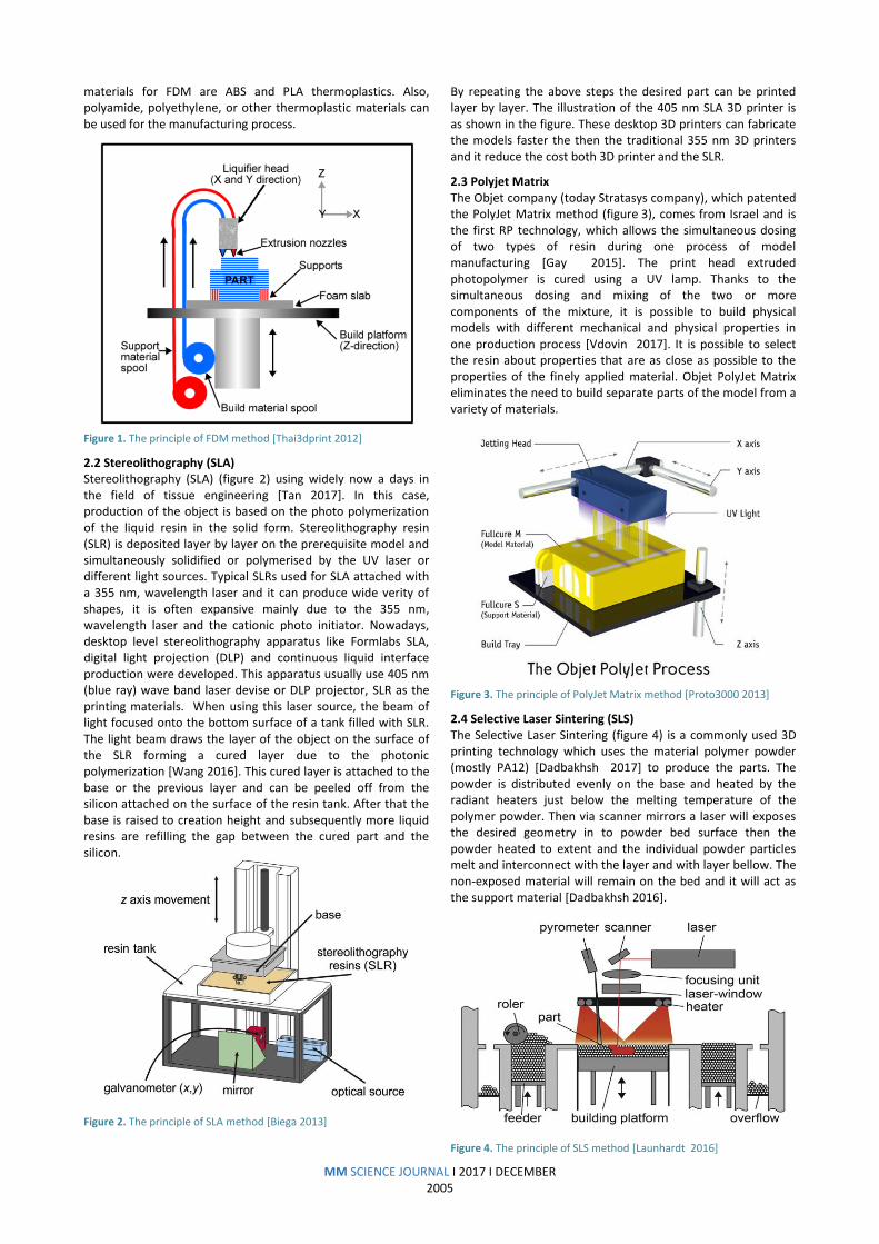
2.1 Fused Deposition Modeling (FDM) Fused Layer Modelling (FLM) or Fused Deposition Modelling (FDM) shown in figure 1, is one of the most widespread additive technologies. This method was developed by S. Scott Crump, who also patented it in 1989 and later founded a company – Stratasys. Most commonly, the principle of the FDM lies in melting a thermoplastic material in a form of a fibre inside an extrusion head that extrudes the melt onto a build platform [Wang 2017]. Due to 2-axis movement it forms a layer of material in the product’s horizontal cross-section plane. The FDM printers usually use two print heads (figure 5). One head builds the supporting structures and the other for layering the model material [Wang 2017]. Layer thickness usually ranges from 127 to 330 micrometres. After finish one layer, the build platform is vertically lowered by the layer thickness, followed by applying another layer [Keller 2016], while this process repeats until the whole product is printed. The supporting structure is created while protruding parts required, after the model printed we can remove the supporting material by the hand or by using some chemical liquid. The most common
MM SCIENCE JOURNAL I 2017 I DECEMBER 2005
materials for FDM are ABS and PLA thermoplastics. Also, polyamide, polyethylene, or other thermoplastic materials can be used for the manufacturing process.
Figure 1. The principle of FDM method [Thai3dprint 2012]
2.2 Stereolithography (SLA) Stereolithography (SLA) (figure 2) using widely now a days in the field of tissue engineering [Tan 2017]. In this case, production of the object is based on the photo polymerization of the liquid resin in the solid form. Stereolithography resin (SLR) is deposited layer by layer on the prerequisite model and simultaneously solidified or polymerised by the UV laser or different light sources. Typical SLRs used for SLA attached with a 355 nm, wavelength laser and it can produce wide verity of shapes, it is often expansive mainly due to the 355 nm, wavelength laser and the cationic photo initiator. Nowadays, desktop level stereolithography apparatus like Formlabs SLA, digital light projection (DLP) and continuous liquid interface production were developed. This apparatus usually use 405 nm (blue ray) wave band laser devise or DLP projector, SLR as the printing materials. When using this laser source, the beam of light focused onto the bottom surface of a tank filled with SLR. The light beam draws the layer of the object on the surface of the SLR forming a cured layer due to the photonic polymerization [Wang 2016]. This cured layer is attached to the base or the previous layer and can be peeled off from the silicon attached on the surface of the resin tank. After that the base is raised to creation height and subsequently more liquid resins are refilling the gap between the cured part and the silicon.
Figure 2. The principle of SLA method [Biega 2013]
By repeating the above steps the desired part can be printed layer by layer. The illustration of the 405 nm SLA 3D printer is as shown in the figure. These desktop 3D printers can fabricate the models faster the then the traditional 355 nm 3D printers and it reduce the cost both 3D printer and the SLR.
2.3 Polyjet Matrix The Objet company (today Stratasys company), which patented the PolyJet Matrix method (figure 3), comes from Israel and is the first RP technology, which allows the simultaneous dosing of two types of resin during one process of model manufacturing [Gay 2015]. The print head extruded photopolymer is cured using a UV lamp. Thanks to the simultaneous dosing and mixing of the two or more components of the mixture, it is possible to build physical models with different mechanical and physical properties in one production process [Vdovin 2017]. It is possible to select the resin about properties that are as close as possible to the properties of the finely applied material. Objet PolyJet Matrix eliminates the need to build separate parts of the model from a variety of materials.
Figure 3. The principle of PolyJet Matrix method [Proto3000 2013]
2.4 Selective Laser Sintering (SLS) The Selective Laser Sintering (figure 4) is a commonly used 3D printing technology which uses the material polymer powder (mostly PA12) [Dadbakhsh 2017] to produce the parts. The powder is distributed evenly on the base and heated by the radiant heaters just below the melting temperature of the polymer powder. Then via scanner mirrors a laser will exposes the desired geometry in to powder bed surface then the powder heated to extent and the individual powder particles melt and interconnect with the layer and with layer bellow. The non-exposed material will remain on the bed and it will act as the support material [Dadbakhsh 2016].
Figure 4. The principle of SLS method [Launhardt 2016]

MM SCIENCE JOURNAL I 2017 I DECEMBER 2006
Once the complete geometry exposed and partially melted then the building platform will lowered one layer and the next layer will applied. This process will continue till the object get over. During the cooling state we will keep the object on the bed to prevent from the thermal distortion
Figure 5. Model production using FDM, PolyJet Matrix, SLA and SLS
3 MANUFACTURING THE TEST SAMPLES Although there is no standard for testing the dimension and geometrical accuracy of parts manufactured by means of additive technologies, an own model (figure 6) based on research and prior experience [Mendricky 2016b] was designed. The base of the model is 100 × 100 mm, the sides of the base are fitted with M6 threads allowing mounting to measurement equipment. The model contains shapes for inspection of basic dimensions, i.e. lengths, distances, angles and diameters of spherical and cylindrical surfaces. Geometry of the model was designed so that it contains as many problematic shapes (elements) as possible (figure 7). The key parts were two planes, five cylinders in different orientations, three identical spheres and distance between them. In addition, it is possible to inspect some deviations of shape and position, such as flatness, parallelism, concentricity of cylindrical surfaces, perpendicularity, etc. It is also possible to evaluate small details. For that purpose, the model is fitted with tiered rectangular through-grooves and circular holes (Figure 5). Distance and size of each of the geometrical object was selected with regards to the 3D scanning performed in the future. It is appropriate to place he objects so they do not unnecessarily overlap each other.
Figure 6. The designed cad model
For the model printed by PolyJet Matrix method, VeroGray material (matte mode – model covered by support material) and one more model with VevoGray material without covered
support material was used (manufacturer Stratasys, tensile strength 50 - 64 MPa, modulus of elasticity 2000 - 3000 MPa, flexural strength 75 - 110 MPa, flexural modulus 2200 - 3200 MPa, Shore hardness 83 - 86 Scale D - more information [stratasys.com 2016], while the layer thickness was set to both, 16 microns (referred to as HQ –High Quality) and 30 microns (referred to as HS –High Speed). In case of FDM technology for both Dimension and Fortus, the most common material was used –ABS-P400 manufacturer Stratasys, tensile strength 22 MPa, modulus of elasticity 1627 MPa, flexural strength 41 MPa, flexural modulus 1834 MPa – more information [Dimension 2011]), while the construction height was constantly 250 microns. Furthermore, a required type of sparse support was selected. In case of FDM printing, solid or sparse high construction materials with high material density was chosen. The structure of Solid offers full internal structure, while on the opposite, the Sparse High enables forming a lightweight internal structure, leading to decrease of construction material consumption and shortening the time necessary to print the model.
Figure 7. 2D drawing of the CAD model
Printer Material Layer
thickness mm
Model
1 FDM
Dimension ABS 0.25 mm Full solid
2 FDM
Dimension ABS 0.25 mm Sparse light
3 FDM
Fortus ABS 0.25 mm Full solid
4 FDM
Fortus ABS 0.25 mm Sparse light
5 PolyJet
Object 500 VevoGray
0.016 mm
Matt
6 PolyJet
Object 500 VevoGray
0.016 mm
Glossy
7 SLS EOS
P3SP PA 2200 0.1 mm
Vertically printed
8 SLS EOS
P3SP PA 2200 0.1 mm
Horizontally printed
9 SLA
Formlabs 2 ABS 0.05 mm
Full model TUL
10 SLA
Ultra ABS 0.05 mm
Full model Out side
Table 1. Properties of the model and the 3D printers used

MM SCIENCE JOURNAL I 2017 I DECEMBER 2007
In total, we printed 10 types of models. Two models created using the FDM method with difference internal structure, two models created by the PolyJet Matrix with difference in support, two models created by the SLA method with different printer machines and two models created by SLS method with different orientation during printing processes. The following table 1 shows the comparison of individual technologies regarding the printing time and consumption of model and supporting material.
4 MEASUREMENT METHODS AND EQUIPMENT USED ATOS system is an optical measurement system whose measurement process is based on the principles of optical triangulation, photometry and fringe projection. It is used in various industries such as construction, manufacturing, quality control, design, etc. The ATOS system can ensure fast and easy digitisation of the measured objects with the relatively high resolution and precision. The most important part of the system is the optical 3d-scanner (figure 8) itself which is consisting of a projector. Each configured sensor defines the size of the 3D area in which the measured object will be scanned- so called measurement volume.
Parameters of ATOS ll 400 optical scanner: Measured volume 250 X 200 X 200 mm Weight 5,200 g Time of 1 scan 1 second Number of points in one can Up to 1,400,00 Point density 0.18 mm Measurement accuracy Approx. 30 μm
Figure 8. Optical scaner ATOS ll 400 [gom.com 2016]
ATOS provides dimensional measurement data and analysis of industrial components, i.e. sheet metal parts, tools, moulds, turbine blades, castings etc. Instead of measuring individual point or by laser, ATOS captures all the geometry and surface components into dense cloud and polygon. ATOS is the broadest use of the system in the areas of CAD, CAM and FEM, [Mendricky 2015] where it is necessary for the measurement of real objects and their comparison with the virtual model. The entire device is designed so that the operator puts the minimal requirements users. Handling sensitive device around the head of the subject is very easy. Since the object is located on the adjustable tripod. Also, there is no need to scan the object after regular sections (e.g.: 200), but it is enough to create the irregular images and makes auxiliary software brands will assess its position. The scanner is supplemented by computer-controlled rotary table. It finds the application in repeating of the same parts.
5 ANALYSIS OF MANUFACTURING ACCURACY Firstly, an analysis of dimensional accuracy was performed. The analysis consisted of inspecting the diameters of spherical and cylindrical surfaces, length dimensions or spacing of the individual elements. Basic geometrical elements (cylinders, spheres, planes, etc.) were calculated by interlacing the fitting elements with Gauss BestFit for 3σ (Figure 9) [Peterkova 2016]. In addition to external and internal diameters, horizontal and vertical cylinders were also evaluated.
Figure 9. Inspection of diameters and the dimension of sphere and spacing between them
Deviation [mm]
Cylinder 1 Ø
Cylinder 2 Ø
Cylinder 3 Ø
Cylinder 4 Ø
FDM Dimension
0.16 mm 0.13 mm 0.09 mm -0.21 mm
FDM Dimension
Spare 0.12 mm 0.09 mm 0.04 mm
-0.18 mm
FDM Fortus
0.16 mm 0.16 mm -0.01 mm
-0.1 mm
FDM Fortus Spare
0 mm 0.06 mm -0.07 mm
-0.08 mm
Poly jet Matte
-0.21 mm
-0.27 mm
-0.21 mm
0.22 mm
Poly jet Glossy
-0.02 mm
-0.04 mm
-0.03 mm
0.01 mm
SLS Vertical
0.04 mm -0.11 mm
-0.02 mm
0.05 mm
SLS Horizontal
-0.15 mm
-0.32 mm
-0.21 mm
-0.05 mm
SLA 0.1 mm 0.03 mm 0.03 mm -0.04 mm
SLA Ultra 0.26 mm 0.23 mm 0.02 mm -0.19 mm
Table 2. Deviation of the nominal cylinder diameters
MM SCIENCE JOURNAL I 2017 I DECEMBER 2008
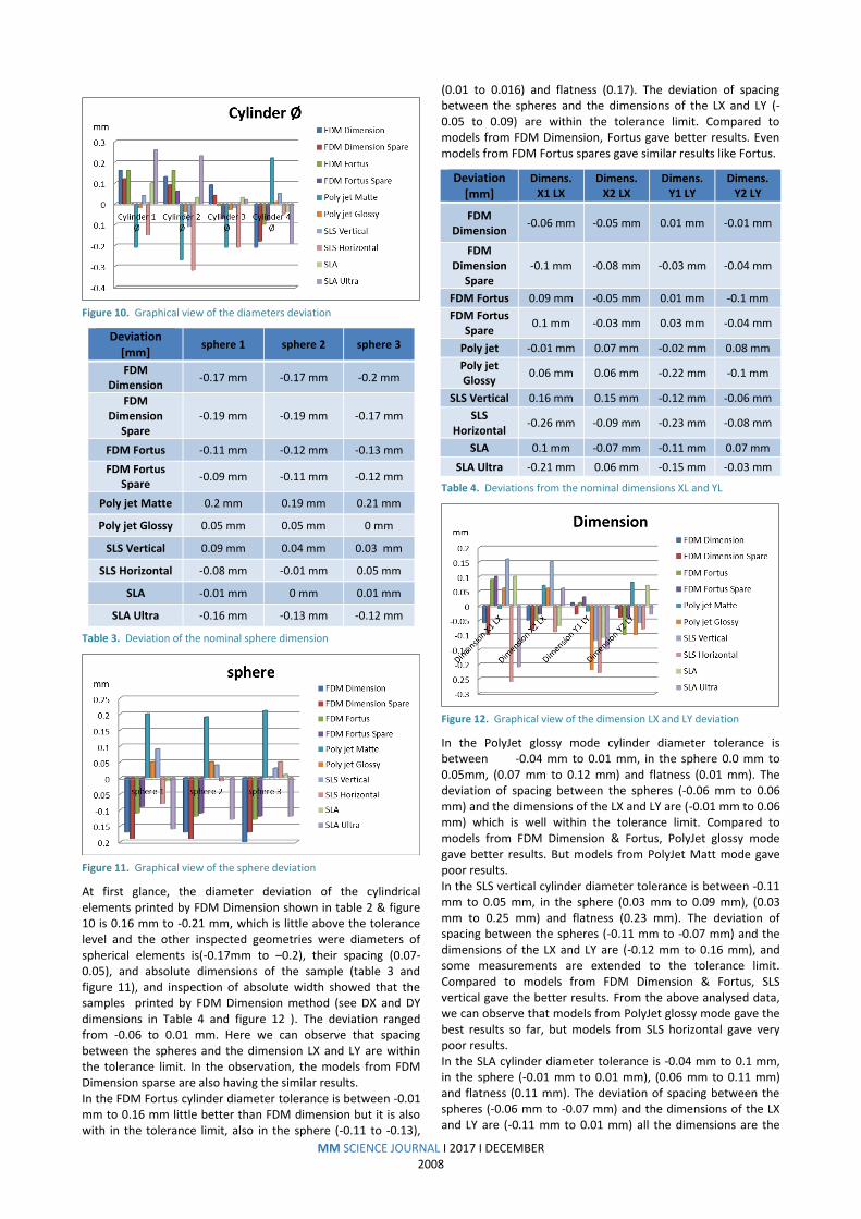
Figure 10. Graphical view of the diameters deviation
Deviation [mm]
sphere 1 sphere 2 sphere 3
FDM Dimension
-0.17 mm -0.17 mm -0.2 mm
FDM Dimension
Spare -0.19 mm -0.19 mm -0.17 mm
FDM Fortus -0.11 mm -0.12 mm -0.13 mm
FDM Fortus Spare
-0.09 mm -0.11 mm -0.12 mm
Poly jet Matte 0.2 mm 0.19 mm 0.21 mm
Poly jet Glossy 0.05 mm 0.05 mm 0 mm
SLS Vertical 0.09 mm 0.04 mm 0.03 mm
SLS Horizontal -0.08 mm -0.01 mm 0.05 mm
SLA -0.01 mm 0 mm 0.01 mm
SLA Ultra -0.16 mm -0.13 mm -0.12 mm
Table 3. Deviation of the nominal sphere dimension
Figure 11. Graphical view of the sphere deviation
At first glance, the diameter deviation of the cylindrical elements printed by FDM Dimension shown in table 2 & figure 10 is 0.16 mm to -0.21 mm, which is little above the tolerance level and the other inspected geometries were diameters of spherical elements is(-0.17mm to –0.2), their spacing (0.07-0.05), and absolute dimensions of the sample (table 3 and figure 11), and inspection of absolute width showed that the samples printed by FDM Dimension method (see DX and DY dimensions in Table 4 and figure 12 ). The deviation ranged from -0.06 to 0.01 mm. Here we can observe that spacing between the spheres and the dimension LX and LY are within the tolerance limit. In the observation, the models from FDM Dimension sparse are also having the similar results. In the FDM Fortus cylinder diameter tolerance is between -0.01 mm to 0.16 mm little better than FDM dimension but it is also with in the tolerance limit, also in the sphere (-0.11 to -0.13),
(0.01 to 0.016) and flatness (0.17). The deviation of spacing between the spheres and the dimensions of the LX and LY (-0.05 to 0.09) are within the tolerance limit. Compared to models from FDM Dimension, Fortus gave better results. Even models from FDM Fortus spares gave similar results like Fortus.
Deviation [mm]
Dimens. X1 LX
Dimens. X2 LX
Dimens. Y1 LY
Dimens. Y2 LY
FDM Dimension
-0.06 mm -0.05 mm 0.01 mm -0.01 mm
FDM Dimension
Spare -0.1 mm -0.08 mm -0.03 mm -0.04 mm
FDM Fortus 0.09 mm -0.05 mm 0.01 mm -0.1 mm
FDM Fortus Spare
0.1 mm -0.03 mm 0.03 mm -0.04 mm
Poly jet -0.01 mm 0.07 mm -0.02 mm 0.08 mm
Poly jet Glossy
0.06 mm 0.06 mm -0.22 mm -0.1 mm
SLS Vertical 0.16 mm 0.15 mm -0.12 mm -0.06 mm
SLS Horizontal
-0.26 mm -0.09 mm -0.23 mm -0.08 mm
SLA 0.1 mm -0.07 mm -0.11 mm 0.07 mm
SLA Ultra -0.21 mm 0.06 mm -0.15 mm -0.03 mm
Table 4. Deviations from the nominal dimensions XL and YL
Figure 12. Graphical view of the dimension LX and LY deviation
In the PolyJet glossy mode cylinder diameter tolerance is between -0.04 mm to 0.01 mm, in the sphere 0.0 mm to 0.05mm, (0.07 mm to 0.12 mm) and flatness (0.01 mm). The deviation of spacing between the spheres (-0.06 mm to 0.06 mm) and the dimensions of the LX and LY are (-0.01 mm to 0.06 mm) which is well within the tolerance limit. Compared to models from FDM Dimension & Fortus, PolyJet glossy mode gave better results. But models from PolyJet Matt mode gave poor results. In the SLS vertical cylinder diameter tolerance is between -0.11 mm to 0.05 mm, in the sphere (0.03 mm to 0.09 mm), (0.03 mm to 0.25 mm) and flatness (0.23 mm). The deviation of spacing between the spheres (-0.11 mm to -0.07 mm) and the dimensions of the LX and LY are (-0.12 mm to 0.16 mm), and some measurements are extended to the tolerance limit. Compared to models from FDM Dimension & Fortus, SLS vertical gave the better results. From the above analysed data, we can observe that models from PolyJet glossy mode gave the best results so far, but models from SLS horizontal gave very poor results. In the SLA cylinder diameter tolerance is -0.04 mm to 0.1 mm, in the sphere (-0.01 mm to 0.01 mm), (0.06 mm to 0.11 mm) and flatness (0.11 mm). The deviation of spacing between the spheres (-0.06 mm to -0.07 mm) and the dimensions of the LX and LY are (-0.11 mm to 0.01 mm) all the dimensions are the

MM SCIENCE JOURNAL I 2017 I DECEMBER 2009
tolerance limit. Compare to models from the remaining technologies SLA gave the best results up to now and PolyJet glossy mode is afterword’s. But models from SLA-ultra gave comparatively poor results.
a) ANALYSIS OF AGING EFFECT (14 DAYS AFTER)
Figure 13. Deviation of the cylinder after 14 days
Figure 14. Deviation of the sphere after 14 days
Figure 15. Deviation of cylindricity after 14 days
These are the results of the models after 14 days maintaining in room temperature and comparing with the day 1 model. Here in figure 13 we can observe that errors after 14 days are similar to Day 1 errors. So, the difference (change in dimensions) is minimal for example the models from SLA and PolyJet glossy mode had change the dimensions very less (0.04 to 0.05 mm) compare to others. Even in figure 14 and 15 we can see that SLA and PolyJet glossy mode gave the best results. In the figure 14 FDM Dimension and SLS vertical also gave the better results but these machines are not maintaining the same minimal deviations in all areas. SLA and PolyJet glossy mode are maintained in all the geometries. Here in this observation we can see that even the models from the best technologies have some geometrical and dimensional changes and by changing the time these deviations of some of
the models are within the limit. Among these, the sparse models show greater deviation in the aging effect.
b) ANALYSIS OF AGING EFFECT (84 DAYS AFTER)
Figure 16. Deviation of the cylinder after 84 days
Figure 17. Deviation of the sphere after 84 days
Figure 18. Deviation of cylindricity after 84 days
Here after 84 days we made the scanning and compared the results with the models scanned on day 1 and we got the same results like what we got on 14 days. Here we can see the figure 16, figure 17 and figure 18 we got the deviations same like day 14. We can also observe that there are no geometrical changes, if you compare figure 20 and figure 21 where you can observe there are no deviations, and therefore geometrical and dimensional deviations after 14 days.

MM SCIENCE JOURNAL I 2017 I DECEMBER 2010
Figure 19. Colour maps of normal deviations
The analysis shows, the highest accuracy was reached by
PolyJet glossy mode with the HQ setting –16 μm layer thickness. The manufacturer states that construction accuracy should range between 0.02 to 0.085 mm depending on used material, geometry of individual parts, model orientation and settings of construction parameters. This requirement was met on most cases (figure 19). FDM Fortus gave better results and overall higher than in case of the samples printed by means of PolyJet Matrix glossy mode. The declared tolerance of construction accuracy
provided by the manufacturer of this printer is 0.127 mm. This requirement was met on most cases (Figure 19). Unfortunately, the other models failed to keep within the tolerance limit for construction accuracy. The analysed results of FDM Dimension samples shows that deviations from the CAD model (table 3 and table 4) did not meet the required conditions. The remaining models from SLA and SLS also failed to keep within the tolerance limit the manufacturer provided the accuracy of printers for both SLS and SLA is 0.10mm, (figure 19).
Figure 20. Colour maps of normal deviations after 14 days
MM SCIENCE JOURNAL I 2017 I DECEMBER 2011
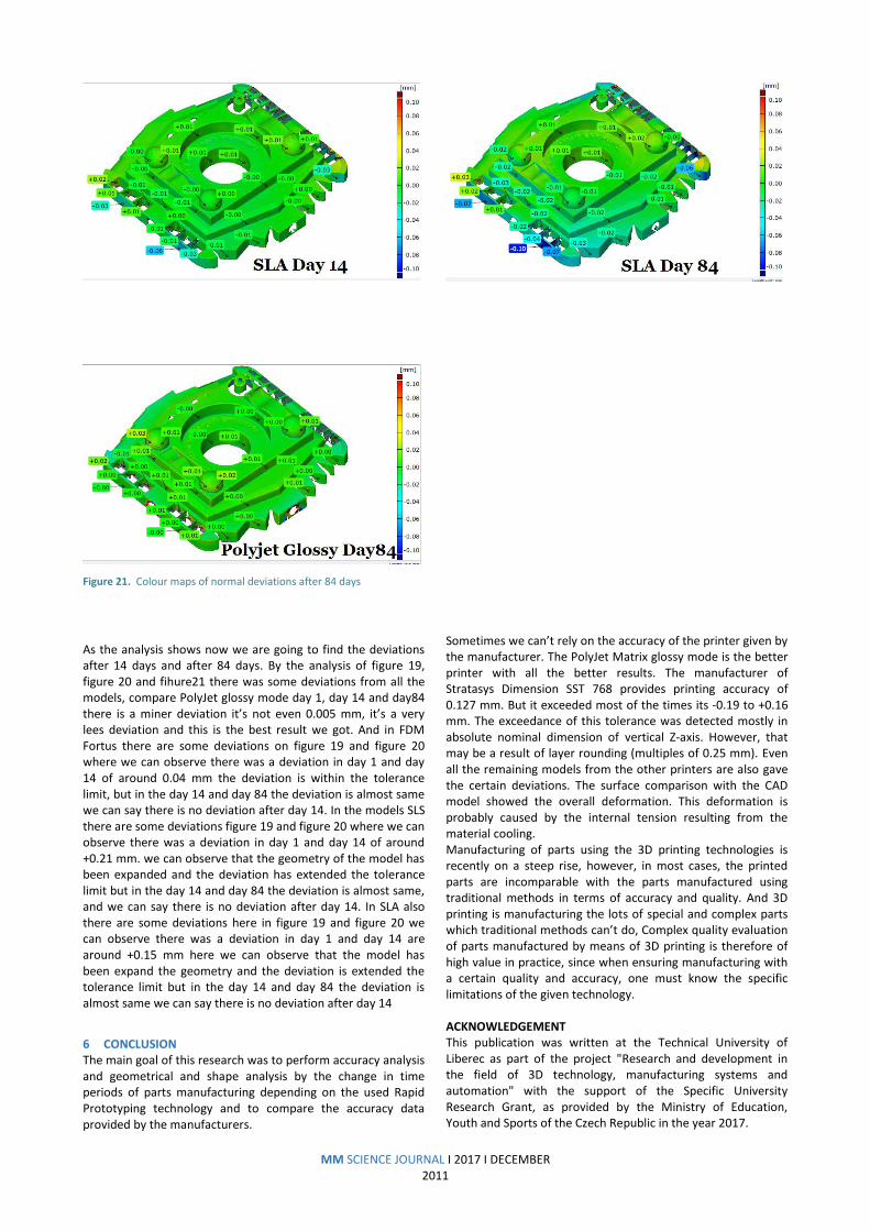
Figure 21. Colour maps of normal deviations after 84 days
As the analysis shows now we are going to find the deviations after 14 days and after 84 days. By the analysis of figure 19, figure 20 and fihure21 there was some deviations from all the models, compare PolyJet glossy mode day 1, day 14 and day84 there is a miner deviation it’s not even 0.005 mm, it’s a very lees deviation and this is the best result we got. And in FDM Fortus there are some deviations on figure 19 and figure 20 where we can observe there was a deviation in day 1 and day 14 of around 0.04 mm the deviation is within the tolerance limit, but in the day 14 and day 84 the deviation is almost same we can say there is no deviation after day 14. In the models SLS there are some deviations figure 19 and figure 20 where we can observe there was a deviation in day 1 and day 14 of around +0.21 mm. we can observe that the geometry of the model has been expanded and the deviation has extended the tolerance limit but in the day 14 and day 84 the deviation is almost same, and we can say there is no deviation after day 14. In SLA also there are some deviations here in figure 19 and figure 20 we can observe there was a deviation in day 1 and day 14 are around +0.15 mm here we can observe that the model has been expand the geometry and the deviation is extended the tolerance limit but in the day 14 and day 84 the deviation is almost same we can say there is no deviation after day 14
6 CONCLUSION The main goal of this research was to perform accuracy analysis and geometrical and shape analysis by the change in time periods of parts manufacturing depending on the used Rapid Prototyping technology and to compare the accuracy data provided by the manufacturers.
Sometimes we can’t rely on the accuracy of the printer given by the manufacturer. The PolyJet Matrix glossy mode is the better printer with all the better results. The manufacturer of Stratasys Dimension SST 768 provides printing accuracy of 0.127 mm. But it exceeded most of the times its -0.19 to +0.16 mm. The exceedance of this tolerance was detected mostly in absolute nominal dimension of vertical Z-axis. However, that may be a result of layer rounding (multiples of 0.25 mm). Even all the remaining models from the other printers are also gave the certain deviations. The surface comparison with the CAD model showed the overall deformation. This deformation is probably caused by the internal tension resulting from the material cooling. Manufacturing of parts using the 3D printing technologies is recently on a steep rise, however, in most cases, the printed parts are incomparable with the parts manufactured using traditional methods in terms of accuracy and quality. And 3D printing is manufacturing the lots of special and complex parts which traditional methods can’t do, Complex quality evaluation of parts manufactured by means of 3D printing is therefore of high value in practice, since when ensuring manufacturing with a certain quality and accuracy, one must know the specific limitations of the given technology. ACKNOWLEDGEMENT This publication was written at the Technical University of Liberec as part of the project "Research and development in the field of 3D technology, manufacturing systems and automation" with the support of the Specific University Research Grant, as provided by the Ministry of Education, Youth and Sports of the Czech Republic in the year 2017.

MM SCIENCE JOURNAL I 2017 I DECEMBER 2012
REFERENCES
[Biega 2013] Biega, 3d printing - technical revolution [online].
© 2013 [cit. 08-11-2017]. http://biega.com/3d-printing.shtml
[Dadbakhsh 2016] Dadbakhsh, S. Verbelen, Leander.
Vandeputte, Tom. Strobbe, Dieter. Van Puyvelde, Peter. Kruth,
Jean-Pierre "Effect of Powder Size and Shape on the SLS
Processability and Mechanical Properties of a TPU Elastomer.",
Vol 83, p. 971-980
Physics Procedia 83: 971-980, ISSN 1875-3892.
[Dadbakhsh 2017] Dadbakhsh, S., Verbelen, L., Verkinderen, O.,
Strobbe, D., Van Puyvelde, P., Kruth, J-P. "Effect of PA12
powder reuse on coalescence behaviour and microstructure of
SLS parts.", Vol 92, p. 250-262,
European Polymer Journal 92: 250-262, ISSN 0014-3057.
[Gay 2015] Gay, P., Blanco, D., Pelayo, F., Noriega, A.,
Fernández, P. Analysis of Factors Influencing the Mechanical
Properties of Flat PolyJet Manufactured Parts.
Vol 132, P. 70-77, ISSN 1877-7058, Procedia Engineering .
[gom.com 2016] High Resolution 3D Scanner from small to
large.
[Keller 2015] Keller, P., Mendricky, R. Parameters Influencing
The Precision Of SLM Production. p. 705-710, Manufacturing
Systems and Automation ,
DOI: 10.17973/MMSJ.2015_10_201540
[Keller 2016] Keller, P. Designing A Compact Dual Head For FLM
3d Printing Technology , P. 1560-1564 Manufacturing Systems
and Automation,
DOI 10.17973/MMSJ.2016_12_2016181
[Launhardt 2016] Launhardt, M., Wörz, A., Loderer, A., Laumer,
T., Drummer, D., Hausotte, T., Schmidt, M. Detecting surface
roughness on SLS parts with various measuring techniques., Vol
53, p. 217-226, Polymer Testing 53: 217-226. ISSN 0142-9418
[Mendricky 2015] Analysis Of Measurement Accuracy Of
Contactless 3D Optical Scanners. p. 711-716 Manufacturing
Systems and Automation
DOI 10.17973/MMSJ.2015_10_201541, [Mendricky 2016a] Accuracy Analysis of Additive Technique for Parts Manufacturing. p. 1502-1508, Manufacturing Systems and Automation, DOI 10.17973/MMSJ.2016_11_2016169.
[Mendricky 2016b] Determination Of Measurement Accuracy
Of Optical 3d Scanners. p.1565-1572 Manufacturing Systems
and Automation
DOI 10.17973/MMSJ.2016_12_2016183
[Peterkova 2016] Peterkova, E., Srefl, M. Use of 3d measuring
system aramis for analysis of tube flaring process. MM Science
Journal, p. 1392-1397, DOI 10.17973/MMSJ.2016_11_2016129
[Proto3000 2013] Proto3000, 3D Engineering Solutions. PolyJet
Matrix 3D Printing Services Process [online]. © 2013 [cit. 08-11-
2017]. Available from: http://proto3000.com/polyjet-matrix-
3d-printing-servicesprocess.php
[stratasys.com 2016] Professional systems in all shapes and
sizes.
[Tan 2017] Tan, W., Suwarno, S. Raditya, S., Jia, A. Fane, Ch. K.,
Chong, A. G., Haur, T. Comparison of solid, liquid and powder
forms of 3D printing techniques in membrane spacer
fabrication. Journal of Membrane Science, Vol 537, P. 283-296,
ISSN 0376-7388
[Thai3dprint 2012] Thai3dprint, Fused deposition modeling
(FDM) [online]. © 2012 [cit. 08-011-2017]. Avilable from:
http://www.mdpi.com/materials/materials-07-
08168/article_deploy/html/images/materials-07-08168-g010-
1024.png. [Vdovin 2017] Vdovin, R., Tomilina, T., Smelov, V., Laktionova, M. Implementation of the Additive PolyJet Technology to the Development and Fabricating the Samples of the Acoustic Metamaterials. Procedia Engineering, Vol 176, P. 595-599, ISSN 595-599. [Wang 2016] Wang, J.,. Goyanes, A., Gaisford, S., Basit, A. W. Stereolithographic (SLA) 3D printing of oral modified-release dosage forms. International Journal of Pharmaceutics, Vol 503(1–2) P. 207-212, ISSN 1877-7058 [Wang 2017] Wang, L., Gardner, D. J. Effect of fused layer modeling (FLM) processing parameters on impact strength of cellular polypropylene. Polymer, Vol 113, P. 74-80, ISSN 0032-3861.
[Wang 2017] Wang, L., Gramlich, W., Gardner, M., Douglas, J.
Improving the impact strength of Poly(lactic acid) (PLA) in fused
layer modeling (FLM). Polymer, Vol 114 P.242-248, ISSN 0032-
3861.
CONTACTS Phaneendra Mantada Ing. Radomír Mendricky, Ph.D.
Ing. Jiri Safka, Ph.D. Technical University of Liberec Faculty of Mechanical Engineering Department of Manufacturing Systems and Automation Studentska 2, 461 17 Liberec 1, Czech Republic +420770698124 [email protected] www.ksa.tul.cz