paper no.: 134 second generation of two-stage ... · pdf filesecond generation of two-stage...
TRANSCRIPT
CONSEIL INTERNATIONALDES MACHINES A COMBUSTION
INTERNATIONAL COUNCILON COMBUSTION ENGINES
PAPER NO.: 134Second generation of two-stage turbocharging
Power2 systems for medium speed gas and dieselengines
Thomas Behr, ABB Turbocharging, SwitzerlandMarkus Kahi, ABB Turbocharging, SwitzerlandArmin Reichl, ABB Turbocharging, Switzerland
Melanie Hubacher, ABB Turbocharging, Switzerland
Abstract: The most important technology driversin the development of modern four-stroke mediumspeed engines are high total engine efficiencies, lowoperating costs and high power density while comply-ing with ever more stringent emission legislation. Inaddition, optimization of initial costs has been con-sidered during development to allow for short pay-back time and thus for a competitive advantage in thearea of power generation where reciprocating enginescompete with gas turbines. Improvement in all areasmentioned above can be achieved with the applica-tion of the latest turbocharging technologies. ABB Tur-bocharging is currently developing the second gen-eration two-stage turbocharging system for mediumspeed gas and diesel engines. The work comprisesa complete portfolio with four sizes covering the entirepower range of large medium speed engines. All com-ponents of this new system will be fully optimized forcombined use in the two-stage system. Completelynew designs are being developed for the thermody-namic components. The focus is on high efficien-cies for fuel savings, system compactness and flexi-ble operation. Axial turbines will be applied for bothlow and high pressure stage. The turbine stage de-signs take into account the diverging needs betweenhigh and low pressure sides. These result from dif-
ferent temperature levels and flow area requirements.And, as contamination build-up is not comparable, thisresults in different turbine cleaning concepts. Com-pressor stage designs are specifically optimized fortwo-stage requirements. Consequently dedicated de-signs, highly efficient and compact turbochargers arebeing realized. Low and high pressure turbocharg-ers will be based on the new concept of an extendedcartridge which will facilitate service down times evenshorter than those on existing single stage applica-tions. The second generation system is the result of astep change development process motivated by fieldexperience gathered from first generation serial sys-tems. Studies presented at the CIMAC conference in2007 revealed that two-stage turbocharging systemswould soon become a commercially attractive alter-native to state-of-the-art single stage turbochargers.Three years later, the first two-stage turbocharger de-signs for medium and high speed gas and diesel en-gines were presented. The first serial engine appli-cations were introduced to the market with claimedbenefits proven. With the development of the sec-ond generation Power2 turbocharging system, ABBTurbocharging provides an optimized technology en-abling full exploitation of the advantages of two-stageturbocharging for large medium speed engines.
©CIMAC Congress 2013, Shanghai
© CIMAC Congress 2013, Shanghai Paper No. 134 2
INTRODUCTION
The most important technology drivers in the development of modern four-stroke medium speed engines are high total engine efficiencies, low operating costs, and high power density while complying with ever more stringent emission legislation [1]. In addition, optimization of initial costs has been considered during development to allow for short pay-back time and thus for a competitive advantage in the area of power generation where reciprocating engines compete with gas turbines. Improvement in all areas mentioned above can be achieved with the application of the latest turbocharging technologies [2] [3].
The use of gaseous fuels driven by emission compliance and fuel prices is nowadays common for many applications while liquid fuels such as HFO, MDO and diesel oil have been dominating these engine segments for decades.
These circumstances have led to strong development activities on both diesel and gas versions of the large medium speed engines. High pressure turbocharging technologies are in both cases a key enabler to achieve the design targets.
The increased pressure and efficiency is utilized in different ways between the diesel and gas engine.
For Diesel engines, Miller cycle and high pressure turbocharging, in particular two-stage turbocharging systems, enables for substantial reduction of NOx emissions while improving fuel efficiency at the same time. Alternatively, highly fuel optimized designs are possible when an SCR catalyst (Selective Catalytic Reduction) is applied for subsequent treatment of the exhaust gases to reduce NOx emissions down to the required level.
The Miller cycle in combination with high pressure turbocharging technology is applied also for gas engines. Here it is the key to avoid the knocking phenomena thus lead to improved engine efficiency, power density as well as good altitude capability.
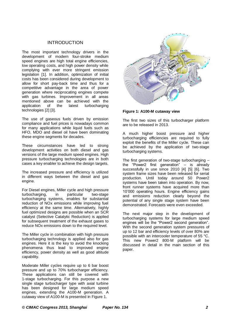
Moderate Miller cycles require up to 6 bar boost pressure and up to 70% turbocharger efficiency. These applications can still be covered with 1-stage turbocharging. For this purpose a new single stage turbocharger type with axial turbine has been designed for large medium speed engines, extending the A100-M generation. A cutaway view of A100-M is presented in Figure 1.
Figure 1: A100-M cutaway view
The first two sizes of this turbocharger platform are to be released in 2013.
A much higher boost pressure and higher turbocharging efficiencies are required to fully exploit the benefits of the Miller cycle. These can be achieved by the application of two-stage turbocharging systems.
The first generation of two-stage turbocharging – the “Power2 first generation” – is already successfully in use since 2010 [4] [5] [6]. Two system frame sizes have been released for serial production. Until today around 50 Power2 systems have been taken into operation. By now, front runner systems have acquired more than 10’000 operating hours. Engine efficiency gains and emissions reduction clearly beyond the potential of any single stage system have been demonstrated. Forecasts were even exceeded.
The next major step in the development of turbocharging systems for large medium speed engines will be the “Power2 second generation”. With the second generation system pressures of up to 12 bar and efficiency levels of over 80% are possible with an intercooler temperature of 55 °C. This new Power2 800-M platform will be discussed in detail in the main section of this paper.

© CIMAC Congress 2013, Shanghai Paper No. 134 3
BENEFITS OF POWER2
Two-stage turbocharging is a key technology contributing to the simultaneous reduction of fuel consumption and emissions as well as enabling an increase of engine power density [7] [8] [9].
Two-stage turbocharging allows for a large reduction of NOx emissions in diesel engines, complying with many of the emission regulations worldwide. For most stringent rules like IMO Tier 3, two-stage turbocharging can be seamlessly integrated with EGR or SCR.
Two-stage turbocharging combined with the Miller cycle on four-stroke engines allows a reduction up to 9% of the specific fuel consumption - considering same NOx emissions - compared to the 1-stage turbocharged counterpart.
Furthermore two-stage turbocharging supports engine power densities well beyond today's most advanced levels with a related potential to reduce specific initial cost of future solutions.
In the first part of this chapter the main advantages of two-stage turbocharging are briefly described, while in the second part the characteristics of ABB’s second generation two-stage turbochargers are presented.
Fuel consumption and NOx emissions
Extreme Miller cycle allow for an appreciable reduction of the overall cycle temperature. This has a direct positive impact on the NOx emissions without affecting the engine efficiency. Figure 2 shows that the engine operation in the well-known bsfc-NOx trade-off diagram is shifted towards a clearly favorable region if combined with the high turbocharging efficiency provided by two-stage turbocharging.
When fully exploiting the potential of Miller cycle and two-stage turbocharging, simulation predicts a NOx reduction of up to 70% and fuel savings of up to 9% compared to a 1-stage reference. The blue line shows the steps along the optimization path to reach the new trade-off curve. Power2 in combination with power density increase, Miller timing and lower valve overlap achieves a considerable benefit. Measurements shown in Figure 2 support the simulation results obtained from first two-stage series applications.
However, it seems that NOx emissions compliant with IMO Tier 3 cannot be reached with Miller cycle and two-stage turbocharging alone at
reasonable levels of fuel consumption or thermal load. Nonetheless the remaining NOx emissions are considerably lower such that leaner EGR or SCR systems can be utilized.
Figure 2: BSFC - NOx trade-off [7] [10]
The air and gas states in the intake and exhaust receiver are important boundary conditions for the gas exchange and in-cylinder process of the internal combustion engine set by the turbocharging system. In particular, the difference between intake and exhaust pressure (engine pressure drop) is relevant for the engine operation, as it has a direct impact on the gas exchange process. In general, a large pressure drop translates into fuel saving.
The driving parameters of the engine pressure drop can be isolated with simple considerations about the energy balance on the turbocharger shaft [11]. The pressure difference over the engine is a function of the overall pressure ratio, the product of turbine inlet temperature and turbocharging efficiency (expressed by parameter c in Equation 1) for constant ambient conditions, system losses and overall air/fuel ratio. From Figure 3 and Equation 1, the following becomes obvious: Turbocharging efficiency and turbine inlet temperature have the same effect on the engine pressure drop.
(1)
As a matter of fact, high turbocharging efficiency is beneficial for any internal combustion engine as it improves the engine pressure drop. On a four-stroke engine it can be assumed that a minimum pressure drop is required to assure proper gas exchange and scavenging in order to account for the flow losses through the valves (pumping work). Every excess value of the pressure drop is converted directly into piston work and contributes to improve engine cycle efficiency.
0
1
23
4
5
6
7
7'
90
95
100
105
0 20 40 60 80 100 120 140 160
Sp
ec
ific
Fu
el
Co
nsu
mp
tio
n [
%]
NOx [%]
Reference Miller - 2-stage turbocharging
Area of achieved results
Challenges• part load
• engine start
• cold combustion
0 Ref IMO1
1 2-stage
2 Power
3 Miller 1
4 Overlap1
5 Miller 2
6 Overlap 2
7 Injection

© CIMAC Congress 2013, Shanghai Paper No. 134 4
Figure 3: Engine pressure drop over pressure ratio [10]
With an unchanged engine configuration, an improvement of turbocharging efficiency produces mainly a reduction of the turbine inlet temperature offsetting some of the benefits. However a valve timing adjustment for a constant temperature permits full use of the turbocharging efficiency for engine efficiency improvement.
Higher pressure ratio at a given air/fuel ratio means either higher brake mean effective pressures or higher Miller effect. The latter is connected with some cycle efficiency losses (Miller loss) which increase with pressure ratio. These losses can be compensated by a high turbocharging efficiency, which is then essential to make extreme Miller with high engine efficiency feasible. Figure 3 shows that for higher pressure ratios a higher turbocharging efficiency is even more important.
Flexibility
The high turbocharging efficiency achievable with two stage turbocharging allows the delivery of the required air pressure in an efficient way and additional power due to the improvement in the gas exchange process.
Intensified Miller cycle and increased power density both drive boost pressure and turbocharging efficiency requirements. A solution is offered providing pressure ratios up to 12 and turbocharging efficiency more than 75% that meets all requirements for next engine generations [12] with ABB’s Power2 second generation turbocharging.
Compactness
For a given intercooler temperature, overall pressure ratio and component efficiency, a defined LP-compressor pressure ratio can be determined for a maximal exploitation of the intercooling, and therefore maximization of the turbocharging efficiency.
The trade-off between equivalent turbocharger efficiency and turbine size is shown in Figure 4. With Power2 second generation the pressure ratio split between LP and HP compressor stage is chosen slightly right of the one corresponding to the optimum of TC efficiency. This definition yields smaller LP turbine area and therefore a more compact design of the LP turbocharger. The HP turbine area is less affected by a split change.
Figure 4: Eq. TC efficiency vs. turbine area
Performance Potential
To show the potential of Power2 second generation an example of two different engine designs is presented in Figure 5 based on simulations. In this example an intercooler temperature of 55 °C and 70 °C is assumed, this declaration is necessary with regard to ηTC,eq. Pressure losses between compressors are assumed to be 50 mbar and between turbines pressure losses are negligible which was already measured on a two-stage application. With these assumptions ηTC,eq > 80% can be achieved at full load.
Figure 5: Eq. TC efficiency over PIC
-1.0
-0.5
0.0
0.5
1.0
1.5
2.0
2.5
3.0
3.5
4.0
1 2 3 4 5 6 7 8 9 10 11 12
pRec - pTI
[bar]
Pressure ratio pC
4-stroke/ 2-stage
4-stroke/ 1-stage
2-stroke/ 1-stage
Automotive
ηT=0.8
ηT=0.75
ηT=0.7
ηT=0.65
ηT=0.6
ηT=0.5
TTI=550 C
TTI=520 C
c=2.4
c=2.2
c=1.8c=1.6c=1.4
November 29, 2012 | Slide 9
© ABB Group
50
100
150
200
250
300
78.0%
78.5%
79.0%
79.5%
80.0%
80.5%
Effe
ctiv
e t
urb
ine
are
a
Equ
ival
en
t TC
eff
icie
ncy
PICLP/ PICHP
Equivalent TC efficiencyEffective LP turbine areaEffective HP turbine area
De
sig
n p
oin
t
January 10, 2013 | Slide 1
© ABB Group
50%
55%
60%
65%
70%
75%
80%
85%
2 4 6 8 10 12
Eq
. T
C e
ffic
ien
cy
Pressure ratio
A100-M
Power2 800-M PIC=9, TIC=55°C
Power2 800-M PIC=9, TIC=70°C
Power2 800-M PIC=12, TIC=55°C
Power2 800-M PIC=12, TIC=70°C
© CIMAC Congress 2013, Shanghai Paper No. 134 5
DESIGN
Thermodynamic boundary conditions and engine requirements of turbochargers operating in a two-stage system differ from the ones of 1-stage turbochargers. Consequently, the design of turbochargers intended for two-stage applications has to reflect these differences in order to achieve an optimum performance.
For the second generation of two-stage turbocharging systems ABB decided to develop entirely new turbocharger designs, which are especially optimized for two-stage requirements. Field experiences gained with the first generation have been incorporated in the design to ensure optimum performance and reliability.
The concepts of the new high-pressure and low-pressure turbocharger have been deduced from the following three main design targets:
Ease of service
Optimum performance
Compactness
These targets have been pursued during development without compromises starting from the overall turbocharger concept down to detail design solutions. The translation of the targets into turbocharger design is explained in more detail in the next sections.
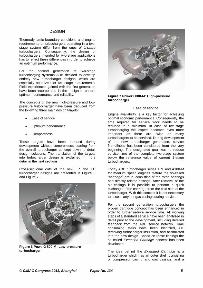
Cross-sectional cuts of the new LP and HP turbocharger designs are presented in Figure 6 and Figure 7.
Figure 6 Power2 800-M: Low-pressure turbocharger
Figure 7 Power2 800-M: High-pressure turbocharger
Ease of service
Engine availability is a key factor for achieving optimal economic performance. Consequently, the time required for service work needs to be reduced to a minimum. In case of two-stage turbocharging this aspect becomes even more important as there are twice as many turbochargers to be serviced. During development of the new turbocharger generation, service friendliness has been considered from the very beginning. The designated goal was to reduce service time of the complete two-stage system below the reference value of current 1-stage turbochargers.
Today ABB turbocharger series TPL and A100-M for medium speed engines feature the so-called “cartridge” group, consisting of the rotor, bearings and directly related casings. After removal of the air casings it is possible to perform a quick exchange of the cartridge from the cold side of the turbocharger. With this concept it is not necessary to access any hot gas casings during service.
For the second generation turbochargers the proven cartridge concept has been enhanced in order to further reduce service time. All working steps of a standard service have been analyzed in detail prior to the development, including detailed feedback from the ABB service network. Time consuming tasks have been identified, i.e. removing turbocharger insulation, and assimilated into the new design. Based on these findings the so called Extended Cartridge concept has been developed.
The idea behind the Extended Cartridge is a turbocharger which has an outer shell, consisting of compressor casing and gas casings, and a

© CIMAC Congress 2013, Shanghai Paper No. 134 6
cartridge group which contains the entire interior of the turbocharger. In order to exchange the cartridge during service, only the air inlet casing together with the insert wall of the compressor needs to be removed. All other interfaces to the engine, such as oil connections, air outlet flange connection, gas inlet and gas outlet flange connections, remain untouched. Furthermore there is no need to remove the insulation of the turbocharger anymore since only the flange connection of the air inlet needs to be accessed during service. A visualization of the Extended Cartridge concept is presented in Figure 8. Parts shaded in grey remain untouched during service. The cartridge group is marked in blue.
A dedicated tool has been developed together with the Extended Cartridge Concept, which enables quick exchange of the cartridge. The tool is used to extract or to insert the cartridge from/into the turbocharger casing. Due to the fact that the associated assembly processes do not require the help of a crane, delays due to limited crane availability or limited accessibility of the turbocharges can be avoided. This aspect becomes more important with two-stage turbocharging systems as the number of turbochargers increases. A crane is needed only once for lifting down the cartridge to the transportation pallet and back. Service time has been further reduced with the help of the newly developed tool.
Figure 8 Extended Cartridge concept
Another contribution to engine downtime reduction is the inspection of turbochargers by endoscopy. With this method the condition of compressor and turbine stages can be checked avoiding unnecessary removal of the cartridge group. Endoscopic inspections are offered by ABB service stations [13].
Optimum performance
Overall system efficiency results from the individual performance of various turbocharger components. Naturally, major contributors are compressor and turbine stages. Additionally, the design frame work around these components needs to be considered to achieve an optimum system performance. Therefore, the design of flow channels and subsystems has been optimized specifically during development of the new turbochargers.
Air inlet casings
The inlet diameter of the impeller wheel and blade height increase significantly due to the high specific volume flow of the low-pressure compressor stage. The flow channel design of the air inlet casings needs to account for this design change. The air inlet flow needs to be turned by an angle of 90° in the case of the radial suction branch. Flow turning should be realized with the smallest space demand at minimum aerodynamic losses despite the increased diameter at the branch outlet. Furthermore, a homogeneous flow distribution at impeller inlet is required to limit blade excitation. In order to be able to satisfy all requirements, an optimization algorithm has been applied in combination with numerical simulations. Figure 9 gives insight into the design process, including design space definitions and final design. As a result of the optimization a pareto-optimal design has been obtained, which attains about 20% reduction in blade vibration excitation potential and about 7% reduction in pressure drop with respect to the initial design.
a) b)
Figure 9 Numerical optimization of LP air suction branch, a) Design range b) Optimization result
Gas outlet flow channel
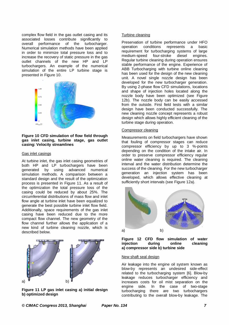
The flow channel from the exit of the turbine rotor until the outlet flange of the gas outlet casing represents a major challenge for aerodynamic design. The flow leaving the turbine rotor in the axial direction will be decelerated in the turbine diffuser before it has to be redirected by 90 degrees towards the outlet flange. The highly
© CIMAC Congress 2013, Shanghai Paper No. 134 7
complex flow field in the gas outlet casing and its associated losses contribute significantly to overall performance of the turbocharger. Numerical simulation methods have been applied in order to minimize total pressure loss and to increase the recovery of static pressure in the gas outlet channels of the new HP and LP turbochargers. An example of the numerical simulation of the entire LP turbine stage is
presented in Figure 10.
Figure 10 CFD simulation of flow field through gas inlet casing, turbine stage, gas outlet casing: Velocity streamlines
Gas inlet casings
At turbine inlet, the gas inlet casing geometries of both HP and LP turbochargers have been generated by using advanced numerical simulation methods. A comparison between a standard design and the result of the optimization process is presented in Figure 11. As a result of the optimization the total pressure loss of the casing could be reduced by about 25%. The circumferential distributions of mass flow and inlet flow angle at turbine inlet have been equalized to generate the best possible turbine inlet flow field. Additionally, space requirements of the gas inlet casing have been reduced due to the more compact flow channel. The new geometry of the flow channel further allows the application of a new kind of turbine cleaning nozzle, which is described below.
a) b)
Figure 11 LP gas inlet casing a) initial design b) optimized design
Turbine cleaning
Preservation of turbine performance under HFO operation conditions represents a basic requirement for turbocharging systems of large medium-speed four-stroke diesel engines. Regular turbine cleaning during operation ensures stable performance of the engine. Experience of ABB Turbocharging with turbine online cleaning has been used for the design of the new cleaning unit. A novel single nozzle design has been developed for the new turbocharger generation. By using 2-phase flow CFD simulations, locations and shape of injection holes located along the nozzle body have been optimized (see Figure 12b). The nozzle body can be easily accessed from the outside. First field tests with a similar design have been conducted successfully. The new cleaning nozzle concept represents a robust design which allows highly efficient cleaning of the
turbine stage during operation.
Compressor cleaning
Measurements on field turbochargers have shown that fouling of compressor stages can reduce compressor efficiency by up to 3 %-points depending on the condition of the intake air. In order to preserve compressor efficiency regular online water cleaning is required. The cleaning interval and the water distribution determine the success of the cleaning. For the new turbocharger generation an injection system has been developed, which allows effective cleaning at
sufficiently short intervals (see Figure 12a).
a) b)
Figure 12 CFD flow simulation of water injection during online cleaning a) compressor side b) turbine side
New shaft seal design
Air leakage into the engine oil system known as blow-by represents an undesired side-effect related to the turbocharging system [6]. Blow-by leakage reduces turbocharger efficiency and increases costs for oil mist separation on the engine side. In the case of two-stage turbocharging there are two turbochargers contributing to the overall blow-by leakage. The
Velocity streamlinesPower2 800-M LP
c/cmax [-]
1.00
0.75
0
0.25
0.50

© CIMAC Congress 2013, Shanghai Paper No. 134 8
high pressure level of the HP turbocharger increases significantly the driving pressure ratio across the shaft seals, which correlates with the leakage rate. Labyrinth shaft seals known from 1-stage axial turbochargers are not sufficient to reduce overall blow-by leakage of a two-stage turbocharging to an acceptable level. Therefore, ABB turbocharging investigated alternative sealing technologies. For the new turbocharger generation a new shaft seal concept will be used for HP and LP turbochargers. In comparison to state-of-the-art labyrinth seals, the new sealing concept reduces blow-by leakage rate by about 75%, which has been confirmed by comparative measurements (Figure 15). With this technology overall blow-by leakage rates of 1-stage turbocharging systems or even below will be achieved with the new two-stage generation.
Figure 13 Measured blow-by leakage rates of labyrinth seal and new sealing design
Miscellaneous
In addition to the aforementioned features further performance optimization measures have been implemented in the new two-stage turbocharging generation. For the HP turbocharger different thrust bearings will be available optimized for the specific thrust ranges minimizing bearing losses. On the compressor side of the HP turbocharger the cooling system of the compressor stage has been optimized to improve cooling efficiency and hence to minimize volumetric losses.
Compactness
Mounting of two-stage turbocharging systems on an engine requires highly compact designs of HP and LP turbochargers. Compactness and aerodynamic performance are generally opposing design targets. Nevertheless, outer dimensions of the turbocharger could be reduced to a minimum through careful aerodynamic optimization of flow channels as described in the previous section. In this way increased specific volume flows of thermodynamic components could be exploited to reduce overall dimensions of the turbocharger when compared to previous generations. Figure 14 shows a relative comparison of filter silencer dimensions of TPL67-C34, Power2 550-M LP
(two-stage first generation) and the new LP turbocharger of Power2 800-M (second generation). The size of the filter silencers has been scaled such that the associated compressor stages would deliver the same volume flow. The comparison shows that new LP filter silencer is about 9% smaller as compared to the one of the scaled TPL67-C34 and about 5% smaller as compared to a scaled first generation LP turbocharger filter silencer. Similar ratios apply to the diameter of the compressor casings.
Figure 14 Relative comparison of filter silencer dimensions of different TC series (scaled to identical compressor volume flow)
Axial length of the turbochargers has been reduced as well to minimum dimensions which are defined by the diameters of the turbocharger flanges. Further reduction would result in an overlap of adjoining flanges (Figure 15).
Figure 15 Axial dimensions of LP turbocharger defined by flange diameters
A compact engine mounting concept becomes possible as a result of the aforementioned dimension optimization measures with the second generation of two-stage turbocharging (Figure 16).
Figure 16 Power2 800-M
November 29, 2012 | Slide 4
© ABB Group
Air inlet Air outlet Gas outlet Gas inlet

© CIMAC Congress 2013, Shanghai Paper No. 134 9
THERMODYNAMIC COMPONENTS
FOR TWO-STAGE TURBOCHARGING
Two-stage turbocharging implies specific requirements on thermodynamic components that differ from the ones of 1-stage systems. Pressure ratios of compressors and turbines in low-pressure and high-pressure turbochargers of two-stage systems are generally different to components in 1-stage turbochargers. With respect to flow areas, differences in fluid density resulting from specific temperatures and pressures in the high and low pressure stages need to be respected. In addition, performance maps of compressors and turbines need to be matched perfectly in order to allow unrestricted engine operation over the entire load range.
With this focus on the specific needs of two-stage turbocharging ABB Turbocharging developed an entirely new set of thermodynamic components optimized for combined application in high-pressure and low-pressure turbochargers of a two-stage system. Individual requirements of each component have been derived from thorough analysis of system optimization studies. In this way, an optimization of system thermodynamic efficiency, operating flexibility and compactness of the system could be achieved. This design strategy implies in reverse that each single thermodynamic component of the high-pressure and low-pressure stage represents an integral part of the overall system.
The challenge for the development of the LP compressor stage was to achieve maximum efficiency in combination with a large performance map width with the smallest possible stage dimension for the required pressure ratio. Figure 17 shows the performance map of the new Power2 800-M LP compressor in comparison to the performance map of a state-of-the-art 1-stage compressor stage. For comparison both stages are scaled to the same impeller wheel diameter. Shaded areas in the plot mark areas of isentropic compressor efficiency greater than 80%. Both stages operate at an efficiency level of up to 84% at design pressure ratio. This comparison visualizes that both compressor stages yield excellent performance at their designated operating points despite the different levels. A large compressor map width could be achieved at design pressure ratio in the case of the new LP compressor stage. Furthermore, the specific volume flow with respect to the impeller wheel diameter has been increased by about 10% when compared to the LP compressor stage of the first generation. The overall dimension of the second
generation LP compressor stage could be further reduced because of this design achievement.
Figure 17 Compressor performance maps of A100-M (1-stage) and Power2 800-M LP (two-stage) at equal impeller wheel diameter
The high-pressure turbocharger features two compressor stage variants, which are specified according to the desired overall pressure ratio. The compressor stage known from the first generation yields optimum performance for
applications with pressure ratios up to C=10. For
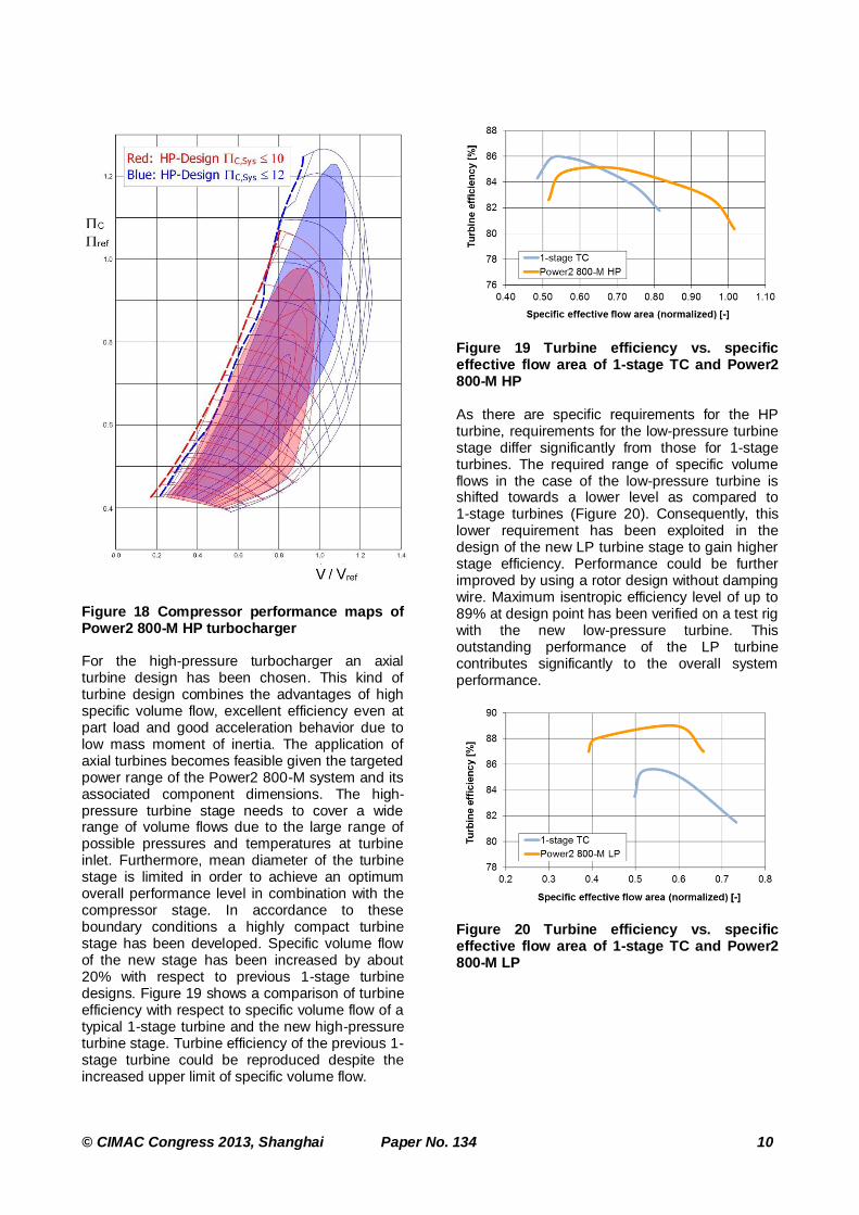
pressure ratios up to C=12 an entirely new HP compressor stage design has been developed. Both stages have been optimized focussing on compressor map width and efficiency at their specific operating range. Performance maps of both stages are presented in Figure 18. Shaded areas in the plot mark areas of isentropic compressor efficiency greater than 80%. Both stages operate at an efficiency level of up to 84% at design pressure ratio.
© CIMAC Congress 2013, Shanghai Paper No. 134 10
Figure 18 Compressor performance maps of Power2 800-M HP turbocharger
For the high-pressure turbocharger an axial turbine design has been chosen. This kind of turbine design combines the advantages of high specific volume flow, excellent efficiency even at part load and good acceleration behavior due to low mass moment of inertia. The application of axial turbines becomes feasible given the targeted power range of the Power2 800-M system and its associated component dimensions. The high-pressure turbine stage needs to cover a wide range of volume flows due to the large range of possible pressures and temperatures at turbine inlet. Furthermore, mean diameter of the turbine stage is limited in order to achieve an optimum overall performance level in combination with the compressor stage. In accordance to these boundary conditions a highly compact turbine stage has been developed. Specific volume flow of the new stage has been increased by about 20% with respect to previous 1-stage turbine designs. Figure 19 shows a comparison of turbine efficiency with respect to specific volume flow of a typical 1-stage turbine and the new high-pressure turbine stage. Turbine efficiency of the previous 1-stage turbine could be reproduced despite the increased upper limit of specific volume flow.
Figure 19 Turbine efficiency vs. specific effective flow area of 1-stage TC and Power2 800-M HP
As there are specific requirements for the HP turbine, requirements for the low-pressure turbine stage differ significantly from those for 1-stage turbines. The required range of specific volume flows in the case of the low-pressure turbine is shifted towards a lower level as compared to 1-stage turbines (Figure 20). Consequently, this lower requirement has been exploited in the design of the new LP turbine stage to gain higher stage efficiency. Performance could be further improved by using a rotor design without damping wire. Maximum isentropic efficiency level of up to 89% at design point has been verified on a test rig with the new low-pressure turbine. This outstanding performance of the LP turbine contributes significantly to the overall system performance.
Figure 20 Turbine efficiency vs. specific effective flow area of 1-stage TC and Power2 800-M LP

© CIMAC Congress 2013, Shanghai Paper No. 134 11
CONCLUSION
A combination of several technology drivers is influencing today the development of large diesel and gas engines. The targets are an increased power density, reduced emissions and high total engine efficiency. The turbocharging system is a major contributor to achieve these targets simultaneously as shown in several publications before. A high pressure single stage turbocharger such as A100 or a two-stage turbocharging system is required for optimal engine performance in more and more cases.
The design of two-stage turbocharging systems introduced in recent years for large medium speed diesel and high speed gas engines are still based partly on technology and concepts derived from single stage turbochargers. Although these systems are already far superior to single stage systems and can fulfill very high pressure ratio and efficiency requirements, they are not taking full advantage of the potential two-stage benefits.
Therefore, ABB Turbocharging has decided to develop the second generation of two-stage turbocharging systems. The Power2 800-M system is characterized by the following features:
Four system sizes covering medium speed engines with bore sizes between approx. 300 and 500 mm.
A system designed for compression pressure ratios up to 12.
Special features such as a newly designed shaft end sealing system are implemented in order to cope with the expected system pressures, while keeping blow-by on a very low level.
New service concept based on an Extended Cartridge enabling service down times equal or shorter than those for single stage turbochargers.
New tool concept supporting the service concept in a most efficient way.
A high flexibility for the pressure ratio split between low pressure and high pressure side was considered in the overall thermodynamic component concept. This takes into account different requirements from the diesel and gas side as well as high altitude installations.
New thermodynamic components enabling a compact design for flexible arrangement on the engine, high natural frequencies and consequently low vibration levels.
Low and high pressure turbochargers both with axial turbines to achieve the required large flow areas and enable an optimal arrangement on the engine.
Completely new turbine stages designed for the specific characteristics of a two-stage system, i.e. very high flow areas on the high pressure unit and outstanding efficiencies on the low pressure side.
A newly designed compressor for the low pressure stage yielding very high efficiencies and specific volume flows.
Two different compressor designs in the high pressure turbocharger to cover the required pressure range with high efficiencies. The well proven stage for higher pressures is newly designed; the stage for lower pressure is taken over from the first generation system.
OUTLOOK
The Power2 800-M system provides for the segment of large four-stroke medium speed engines full flexibility to implement future technologies for emission reduction, high power density and high fuel efficiency.
The next foreseeable step in the development process is the design of a second generation system for smaller engines in the high speed gas engine segment. Such a system will also be highly optimized for the specific engine segment requirements. It is expected, that similar compressor stages as in the Power2 800-M system can also be used in this system as the thermodynamic requirements are quite similar.

© CIMAC Congress 2013, Shanghai Paper No. 134 12
NOMENCLATURE
LP Low pressure
HP High pressure
TC Turbocharger
Mass flow turbine inlet
Mass flow compressor outlet
Temperature turbine inlet
Temperature compressor inlet
Turbocharging efficiency
REFERENCES
[1] VDMA, 2008, Exhaust Emission legislation, Diesel- and Gas Engines, VDMA Engines and Systems, Frankfurt am Main (D).
[2] Codan e. et al.: IMO III Emission Regulation : Impact on the Turbocharging System, Paper No. 139, CIMAC 2010 Bergen.
[3] Christen, C., Codan, E.: Engine Control and Performance Enhancement with Variable Valve Train for Gas Engines, 16. Aufladetechnische Konferenz, Dresden, 2011.
[4] Raikio, T., Hallback, B., Hjort, A.: Design and first application of a two-stage turbocharging system for a medium-speed diesel engine, Paper NO. 82, CIMAC, Bergen, 2010.
[5] Laiminger, S, Trapp, C., Schaumberger, H., Fouquet, M.: Die nächste Generation von Jenbacher Gasmotoren von GE – die wegweisende Kombination von zweistufiger Aufladung und innovativen Brennverfahren, 7
th Dessau Gas Engine Conference, Dessau,
2011.
[6] Tinschmann, G., Lang, J., Thalhauser, J., Klausner, J., Amplatz, E., Trapp, C.: Gas Engines with Two Stage Turbocharging – Field Experience, Design Opportunities for different Applications, further Development, 17. Aufladetechnische Konferenz, Dresden, 2012.
[7] Codan, E, et al: two-stage Turbocharging Flexibility for Engine Optimization, Paper NO. 293, CIMAC, Bergen, 2010.
[8] Wik, C., Hallback, B.: Utilisation of two-stage turbo charging as an emission reduction mean on a Wärtsilä four-stroke medium-speed diesel engine, Paper NO. 101, CIMAC Vienna, 2007.
[9] Wirth, K., Rickert, C., Schlemmer-Kelling, U., Die Entwicklung der Baureihe M 32 – Eine
Erfolgsgeschichte, 2. Rostocker Gross-motorentagung, Rostock, 2012.
[10] Codan, E., et al: Applications and Potentials of two-stage turbocharging, 14. Auflade-technische Konferenz, Dresden, 2009.
[11] Meier, E., Part load operation of very high turbocharged four-stroke marine diesel engines, CIMAC, Paris, 1983.
[12] Millo, F., Gianiglio, M., Delneri, D.: Combining dual stage turbocharging with extreme Miller timings to achieve NOx emissions reductions in marine diesel engines, Paper NO. 210, CIMAC, Bergen, 2010.
[13] Neuenschwander, P. et al: New turbochargers for more powerful engines running under stricter regimes, CIMAC, Bergen, 2010.