4640e power2/5240e power2 operator's manual
TRANSCRIPT

Skid-Steer LoadersO
pera
tor’
s M
anua
l
Form No.50950012/
AP0811English
SL4640ESL4640E (EU)Power2(SN 312901 and Up)
SL5240ESL5240E (EU)Power2(SN 432501 and Up)
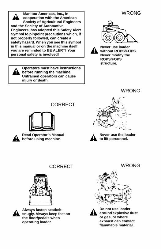
Manitou Americas, Inc., in cooperation with the American Society of Agricultural Engineers
and the Society of Automotive Engineers, has adopted this Safety Alert Symbol to pinpoint precautions which, if not properly followed, can create a safety hazard. When you see this symbol in this manual or on the machine itself, you are reminded to BE ALERT! Your personal safety is involved!
Operators must have instructions before running the machine. Untrained operators can cause injury or death.
Read Operator’s Manual before using machine.
CORRECT
Always fasten seatbelt snugly. Always keep feet on the floor/pedals when operating loader.
CORRECT
Never use loader without ROPS/FOPS. Never modify the ROPS/FOPS structure.
WRONG
Never use the loader to lift personnel.
WRONG
Do not use loader around explosive dust or gas, or where exhaust can contact flammable material.
WRONG

Introduction . . . . . . . . . . . . . . . . . . . . . . . . . . . . . . . . . . . . 1Safety . . . . . . . . . . . . . . . . . . . . . . . . . . . . . . . . . . . . . . . . 5Controls and Safety Equipment . . . . . . . . . . . . . . . . . . . 19Operation . . . . . . . . . . . . . . . . . . . . . . . . . . . . . . . . . . . . 43Service . . . . . . . . . . . . . . . . . . . . . . . . . . . . . . . . . . . . . . 57Troubleshooting . . . . . . . . . . . . . . . . . . . . . . . . . . . . . . . 81Maintenance . . . . . . . . . . . . . . . . . . . . . . . . . . . . . . . . . . 91Specifications . . . . . . . . . . . . . . . . . . . . . . . . . . . . . . . . . 95Torque Specifications . . . . . . . . . . . . . . . . . . . . . . . . . . 103Warranty . . . . . . . . . . . . . . . . . . . . . . . . . . . . . . . . . . . . 104INDEX . . . . . . . . . . . . . . . . . . . . . . . . . . . . . . . . . . . . . . 105
SL4640E, SL4640E (EU) and SL5240E, SL5240E (EU) Power2 Skid-Steer Loader Operator’s Manual
TABLE OF CONTENTS
Hydraloc and Hydraglide are trademarks of Manitou Americas, Inc.Gehl, All-Tach, Power-A-Tach and Powerview are registered trademarks of Manitou Americas, Inc.
Loader Model Number
Loader Serial Number
Engine Serial Number

EC DECLARATION OF CONFORMITY
1. Manufacturer: Manitou Americas, Inc.
2. Address: One Gehl Way West Bend, WI 53095-0179 U.S.A.
3. Technical Construction File Location: Manitou Interface and Logistics Europe SA/NV Chaussée de Wavre SN 1360 PERWEZ Belgium
4. Authorized Representative:
5. Address:
6. We hereby declare that the model(s) listed below conforms to EC Directives: 2004/108/EC (EMC), 97/23/EC (Pressure Equipment), 2006/42/EC (Machinery) and 2000/14/EC (Noise Emission), as amended by 2005/88/EC.
7. In accordance with EN/ISO Standards: EN ISO 3450:1996, ISO 6165
8. Category: EARTH-MOVING MACHINERY/ LOADERS/COMPACT
9. Model(s): 4640E Power2, 5240E Power2
10. Directive/Conformity Assessment Procedure/Notified Body:
2004/108/EC Type-test Self-certification
97/23/EC Self-certification ----------
2006/42/EC Self-certification ----------
2000/14/EC Annex VIII – Full Quality Assurance
TÜV Industrie Service GmbH – TÜV SÜD Group Westendst. 199, D-80686 München GERMANY

CHAPTER 1INTRODUCTION
This Operator’s Manual provides the owner/operator with information for operat-ing, maintaining and servicing Gehl SL4640E and 5240E Power2 skid-steer load-ers. More important, this manual provides an operating plan for safe and proper useof the machine. Major points of safe operation are detailed in the Safety chapter ofthis manual.
We ask that you read and understand the contents of this manual completely andbecome familiar with your new machine before operating it. See your authorizedGehl dealer if you have any questions concerning information in the manual,require extra manuals or for information concerning the availability of manuals inother languages.
Throughout this manual, information is provided set in italic type and introducedby the word Note or Important. Read carefully and comply with those messages –it will improve your operating and maintenance efficiency, help avoid breakdownsand damage, and extend your machine’s life.
A manual storage box in the operator’s compartment holds the Operator’s Manualand AEM Safety Manual (also available in Spanish). Please return the manuals tothis box and keep them with the unit at all times. If this machine is resold, we rec-ommend that these manuals be given to the new owner.
The attachments and equipment available for use with this machine have a widevariety of potential applications. Read the manual provided with the attachment tolearn how to safely maintain and operate the equipment. Be sure the machine issuitably equipped for the type of work to be performed.
Do not use this machine for any applications or purposes other than thosedescribed in this manual or those applicable for approved attachments. If themachine is to be used with special attachments or equipment other than thoseapproved by Manitou Americas, consult your Gehl dealer. Any person using non-approved attachments or making unauthorized modifications is responsible for theconsequences.
The Gehl dealership network stands ready to provide you with any assistance youmay require, including providing genuine Gehl service parts. All service partsshould be obtained from your Gehl dealer. Provide complete information about thepart and include the model and serial numbers of your machine. Record these num-bers in the space provided on the Table of Contents page, as a handy reference.
Manitou Americas strives to continuously improve its products and reserves theright to make changes and improvements in the design and construction of any partwithout incurring the obligation to install such changes on any previously deliv-ered unit.
50950012/AP0811 1

If this machine was purchased “used,” or if the owner’s address has changed,please provide your Gehl dealer or Gehl Company Service Department with theowner’s name and current address, along with the machine model and serial num-ber. This will allow the registered owner information to be updated, so that theowner can be notified directly in case of an important product issue, such as asafety update program.
2 50950012/AP0811
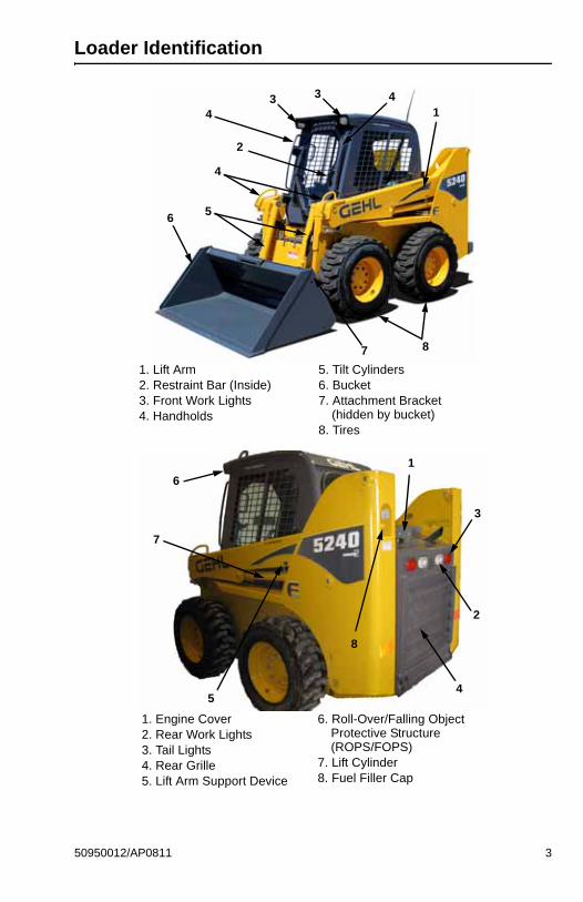
Loader Identification
1. Lift Arm2. Restraint Bar (Inside)3. Front Work Lights4. Handholds
5. Tilt Cylinders6. Bucket7. Attachment Bracket
(hidden by bucket)8. Tires
3
56
7 8
2
1
8
4
3 4
4
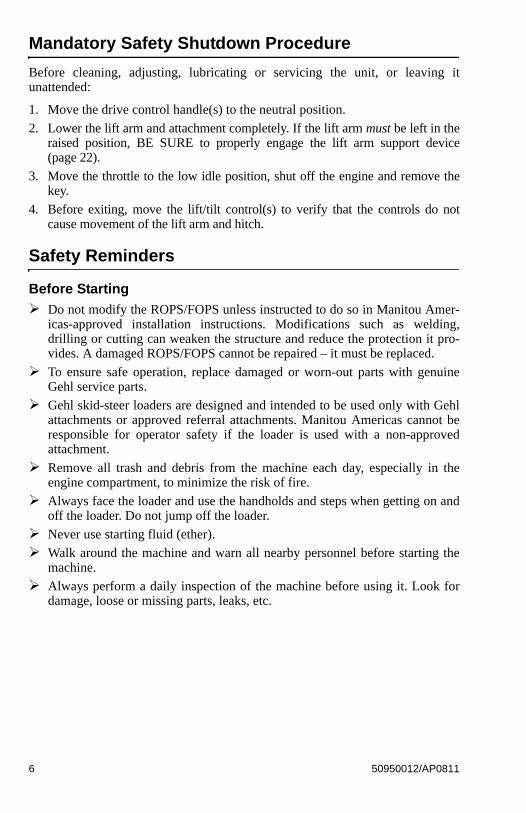
1. Engine Cover2. Rear Work Lights3. Tail Lights4. Rear Grille5. Lift Arm Support Device
6. Roll-Over/Falling Object Protective Structure(ROPS/FOPS)
7. Lift Cylinder8. Fuel Filler Cap
3
3
4
1
2
6
7
8
5
50950012/AP0811 3

Control/Indicator Symbols
Power Off Power On Engine Start Battery Charge Electrical Power
Worklight w/Flasher Worklight Safety Alert Hazard Flasher Wear Seatbelt
Horn Read Operator’s Manual
Volume – Full Volume – Half Full Volume – Empty
H-LHigh – Low
NNeutral
FForward
RReverse Parking Brake
Engine Air Filter Engine Oil Engine Oil Filter Engine Oil Pressure Fuel Filter
Engine Temperature Hydraulic System Hydraulic Oil Temperature
Hydraulic Oil Filter Grease Lubrication Point
Glow Indicator Lamp
Diesel Fuel Chaincase Oil Clockwise Rotation Counterclockwise Rotation
Fast Speed Slow Speed Ride Control Power-A-Tach® Bucket – Float
Bucket – Rollback Bucket – Dump Lift Arm – Lower Lift Arm – Raise Service Hours
Lift Point Tie-Down Point Diesel Water Separator
Engine Malfunction Shutdown
4 50950012/AP0811

CHAPTER 2SAFETY
This safety alert symbol means Attention! Become alert! Your safety isinvolved! It stresses an attitude of safety awareness and can be found
throughout this Operator’s Manual and on the decals on the machine.
Before operating this machine, read and study the following safety information.For further reference on the safe operation of skid-steer loaders, Manitou Amer-icas suggests that equipment owners obtain the Gehl “Skid-Steer Loader Safety”DVD, which is available through Gehl dealers. In addition, be sure that everyonewho operates or works with this machine, whether family member or employee,is familiar with these safety precautions. It is essential to have competent andcareful operators, who are not physically or mentally impaired, and who are thor-oughly trained in the safe operation of the machine and the handling of loads. It isrecommended that the operator be capable of obtaining a valid motor vehicleoperator’s license.
The use of skid-steer loaders is subject to certain hazards that cannot be eliminatedby mechanical means, but only by exercising intelligence, care and common sense.Such hazards include, but are not limited to, hillside operation, overloading, insta-bility of the load, poor maintenance and using the equipment for a purpose forwhich it is not intended or designed.
Manitou Americas ALWAYS considers the operator’s safety when designing itsmachinery, and guards exposed moving parts for the operator’s protection. How-ever, some areas cannot be guarded or shielded in order to assure proper opera-tion. Furthermore, this Operator’s Manual and decals on the machine warn ofadditional hazards and they should be read and observed closely.
Some photographs in this manual may show doors, guards and shields open orremoved for illustrative purposes only. Be sure that all doors, guards and shieldsare in their proper operating positions before starting the engine to operate theunit.
Different applications may require optional safety equipment, such as a back-upalarm, mirror, strobe light or an impact-resistant front door. Be sure you know thejob site hazards and equip the machine as needed.
“DANGER” indicates an imminently haz-ardous situation, which, if not avoided, will
result in death or serious injury.
“WARNING” indicates a potentially hazardoussituation, which, if not avoided, could result
in death or serious injury.
“CAUTION” indicates a potentially hazardoussituation, which, if not avoided, may result in
minor or moderate injury. May also alert against unsafe practices.
DANGER
WARNING
CAUTION
50950012/AP0811 5
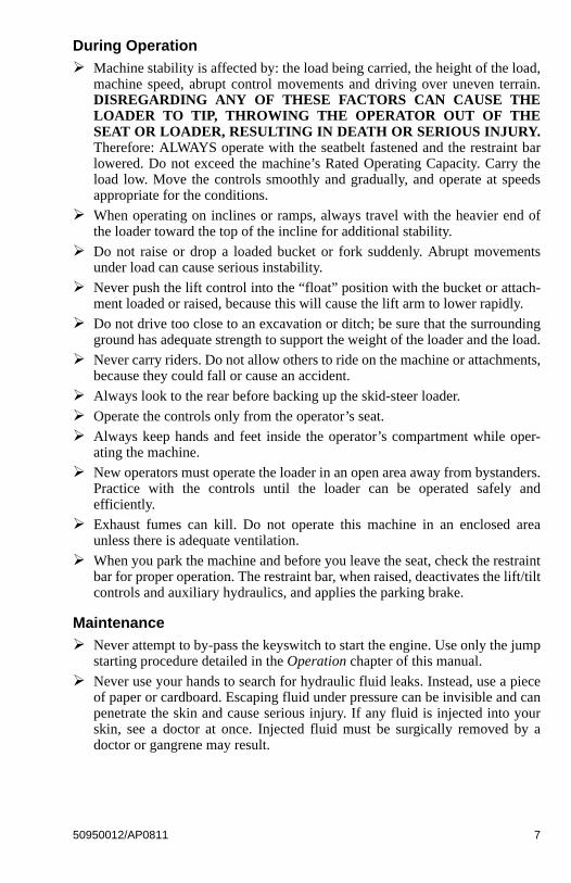
Mandatory Safety Shutdown Procedure
Before cleaning, adjusting, lubricating or servicing the unit, or leaving itunattended:
1. Move the drive control handle(s) to the neutral position.
2. Lower the lift arm and attachment completely. If the lift arm must be left in theraised position, BE SURE to properly engage the lift arm support device(page 22).
3. Move the throttle to the low idle position, shut off the engine and remove thekey.
4. Before exiting, move the lift/tilt control(s) to verify that the controls do notcause movement of the lift arm and hitch.
Safety Reminders
Before Starting
Do not modify the ROPS/FOPS unless instructed to do so in Manitou Amer-icas-approved installation instructions. Modifications such as welding,drilling or cutting can weaken the structure and reduce the protection it pro-vides. A damaged ROPS/FOPS cannot be repaired – it must be replaced.
To ensure safe operation, replace damaged or worn-out parts with genuineGehl service parts.
Gehl skid-steer loaders are designed and intended to be used only with Gehlattachments or approved referral attachments. Manitou Americas cannot beresponsible for operator safety if the loader is used with a non-approvedattachment.
Remove all trash and debris from the machine each day, especially in theengine compartment, to minimize the risk of fire.
Always face the loader and use the handholds and steps when getting on andoff the loader. Do not jump off the loader.
Never use starting fluid (ether).
Walk around the machine and warn all nearby personnel before starting themachine.
Always perform a daily inspection of the machine before using it. Look fordamage, loose or missing parts, leaks, etc.
6 50950012/AP0811
During Operation
Machine stability is affected by: the load being carried, the height of the load,machine speed, abrupt control movements and driving over uneven terrain.DISREGARDING ANY OF THESE FACTORS CAN CAUSE THELOADER TO TIP, THROWING THE OPERATOR OUT OF THESEAT OR LOADER, RESULTING IN DEATH OR SERIOUS INJURY.Therefore: ALWAYS operate with the seatbelt fastened and the restraint barlowered. Do not exceed the machine’s Rated Operating Capacity. Carry theload low. Move the controls smoothly and gradually, and operate at speedsappropriate for the conditions.
When operating on inclines or ramps, always travel with the heavier end ofthe loader toward the top of the incline for additional stability.
Do not raise or drop a loaded bucket or fork suddenly. Abrupt movementsunder load can cause serious instability.
Never push the lift control into the “float” position with the bucket or attach-ment loaded or raised, because this will cause the lift arm to lower rapidly.
Do not drive too close to an excavation or ditch; be sure that the surroundingground has adequate strength to support the weight of the loader and the load.
Never carry riders. Do not allow others to ride on the machine or attachments,because they could fall or cause an accident.
Always look to the rear before backing up the skid-steer loader.
Operate the controls only from the operator’s seat.
Always keep hands and feet inside the operator’s compartment while oper-ating the machine.
New operators must operate the loader in an open area away from bystanders.Practice with the controls until the loader can be operated safely andefficiently.
Exhaust fumes can kill. Do not operate this machine in an enclosed areaunless there is adequate ventilation.
When you park the machine and before you leave the seat, check the restraintbar for proper operation. The restraint bar, when raised, deactivates the lift/tiltcontrols and auxiliary hydraulics, and applies the parking brake.
Maintenance
Never attempt to by-pass the keyswitch to start the engine. Use only the jumpstarting procedure detailed in the Operation chapter of this manual.
Never use your hands to search for hydraulic fluid leaks. Instead, use a pieceof paper or cardboard. Escaping fluid under pressure can be invisible and canpenetrate the skin and cause serious injury. If any fluid is injected into yourskin, see a doctor at once. Injected fluid must be surgically removed by adoctor or gangrene may result.
50950012/AP0811 7

Always wear safety glasses with side shields when striking metal againstmetal. In addition, it is recommended that a softer (chip-resistant) material beused to cushion the blow. Failure to heed could lead to serious injury to theeyes or other parts of the body.
Do not smoke or have any spark-producing equipment in the area while fillingthe fuel tank or while working on the fuel or hydraulic systems.
Potential Hazards
A skid-steer loader operator must ALWAYS be conscious of the working envi-ronment. Operator actions, the environmental conditions and the job being per-formed require the full attention of the operator so that safety precautions can betaken.
ALWAYS maintain a safe distance from electric power lines and avoid contactwith any electrically charged conductor or gas line. It is not necessary to makedirect contact with a power line for power to ground through the structure of themachine. Accidental contact or rupture can result in electrocution or an explo-sion. Contact the North American One-Call Referral System at: 8-1-1 in the U.S.,or 1-888-258-0808 in the U.S. and Canada for the local “Digger’s Hotline”number or the proper local authorities for utility line locations BEFORE startingto dig!
Exposure to crystalline silica (found in sand, soil and rocks) has been associatedwith silicosis, a debilitating and often fatal lung disease. A Hazard Review(Pub. No. 2002-129) by the U.S. National Institute for Occupational Safety andHealth (NIOSH) indicates a significant risk of chronic silicosis for workersexposed to inhaled crystalline silica over a working lifetime. NIOSH recom-mends an exposure limit of 0.05 mg/m3 as a time-weighted average for up to a10-hr workday during a 40-hr workweek. NIOSH also recommends substitutingless hazardous materials when feasible, using respiratory protection and regularmedical examinations for exposed workers.
Safety Decals
The skid-steer loader has decals that provide safety information and precautionsaround the loader. These decals must be kept legible. If missing or illegible, theymust be replaced promptly. Replacements can be obtained from your Gehl dealer.New equipment must have all decals specified by the manufacturer affixed intheir proper locations. If there is a decal on a part that is being replaced, be surethat the decal is applied to the replacement part.
New Decal ApplicationSurfaces must be free of dirt, dust, grease and foreign material before applyingthe decal. Remove the smaller portion of the decal backing paper and apply theexposed adhesive to the clean surface, maintaining proper position and align-ment. Peel the rest of the backing paper and apply hand pressure to smooth outthe decal surface. Refer to the following pages for proper decal location. Textdecals begin on page 9; no-text decals begin on page 13.
8 50950012/AP0811
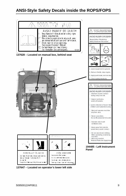
ANSI-Style Safety Decals inside the ROPS/FOPS
137628 – Located on manual box, behind seat
P
Always follow "MandatorySafety Shutdown Procedure".
STOP
AVOID INJURY OR DEATH
Maintain 3-point contact during entry and exit.
Inspect work area, avoid all hazards.
Look in direction of travel. Keep children and bystanders away.
Start and operate machine only from seat.
Never carry riders. Do not lift personnel in bucket.
Operate only in well ventilated area.
Keep away from electric power l ines, avoid contact.
Do not wear loose clothingWhen operating or servicingmachine. Wear any needed
Personal Protective Equipment.
AVOID INJURY OR DEATH
1 2
3 4
1. Lower equipment to ground.
2. Reduce throttle, stop engine.
3. Apply park brake; remove key.
4. Check safety interlocks.
194485 - Left Instrument Panel
137647 – Located on operator’s lower left side
50950012/AP0811 9
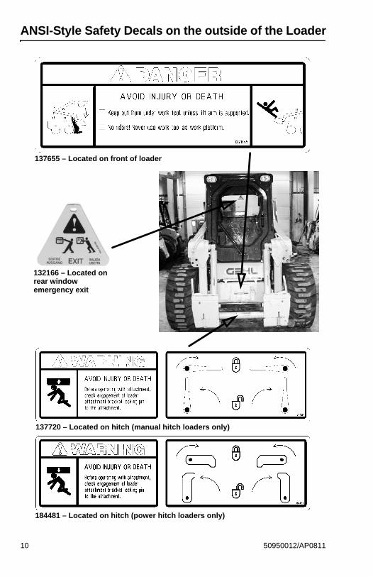
ANSI-Style Safety Decals on the outside of the Loader
137655 – Located on front of loader
132166 – Located on rear window emergency exit
137720 – Located on hitch (manual hitch loaders only)
184481 – Located on hitch (power hitch loaders only)
10 50950012/AP0811
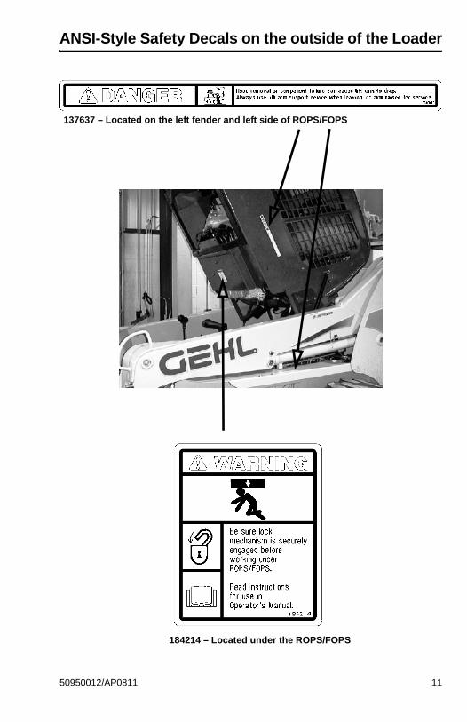
ANSI-Style Safety Decals on the outside of the Loader
137637 – Located on the left fender and left side of ROPS/FOPS
184214 – Located under the ROPS/FOPS
50950012/AP0811 11
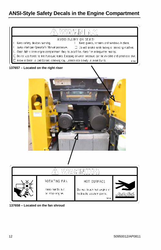
ANSI-Style Safety Decals in the Engine Compartment
137657 – Located on the right riser
137658 – Located on the fan shroud
12 50950012/AP0811
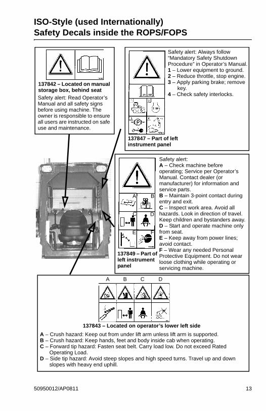
ISO-Style (used Internationally) Safety Decals inside the ROPS/FOPS
A – Crush hazard: Keep out from under lift arm unless lift arm is supported.B – Crush hazard: Keep hands, feet and body inside cab when operating.C – Forward tip hazard: Fasten seat belt. Carry load low. Do not exceed Rated
Operating Load.D – Side tip hazard: Avoid steep slopes and high speed turns. Travel up and down
slopes with heavy end uphill.
Safety alert: Read Operator’s Manual and all safety signs before using machine. The owner is responsible to ensure all users are instructed on safe use and maintenance.
137842 – Located on manual storage box, behind seat
137847 – Part of left instrument panel
Safety alert: Always follow “Mandatory Safety Shutdown Procedure” in Operator’s Manual.1 – Lower equipment to ground.2 – Reduce throttle, stop engine.3 – Apply parking brake; remove
key.4 – Check safety interlocks.
137849 – Part of left instrument panel
Safety alert:A – Check machine before operating; Service per Operator’s Manual. Contact dealer (or manufacturer) for information and service parts.B – Maintain 3-point contact during entry and exit.C – Inspect work area. Avoid all hazards. Look in direction of travel. Keep children and bystanders away.D – Start and operate machine only from seat.E – Keep away from power lines; avoid contact.F – Wear any needed Personal Protective Equipment. Do not wear loose clothing while operating or servicing machine.
A B
C D
E F
137843 – Located on operator’s lower left side
A B C D
50950012/AP0811 13
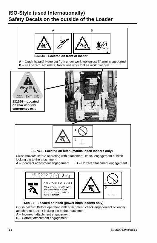
ISO-Style (used Internationally) Safety Decals on the outside of the Loader
186743
186743 – Located on hitch (manual hitch loaders only)
Crush hazard: Before operating with attachment, check engagement of hitch locking pin to the attachment:A – Incorrect attachment engagement B – Correct attachment engagement
137844 – Located on front of loader
132166 – Located on rear window emergency exit
139101 – Located on hitch (power hitch loaders only)
A – Crush hazard: Keep out from under work tool unless lift arm is supported.B – Fall hazard: No riders. Never use work tool as work platform.
Crush hazard: Before operating with attachment, check engagement of loader attachment bracket locking pin to the attachment:A – Incorrect attachment engagementB – Correct attachment engagement
A B
A
B
A
B
14 50950012/AP0811
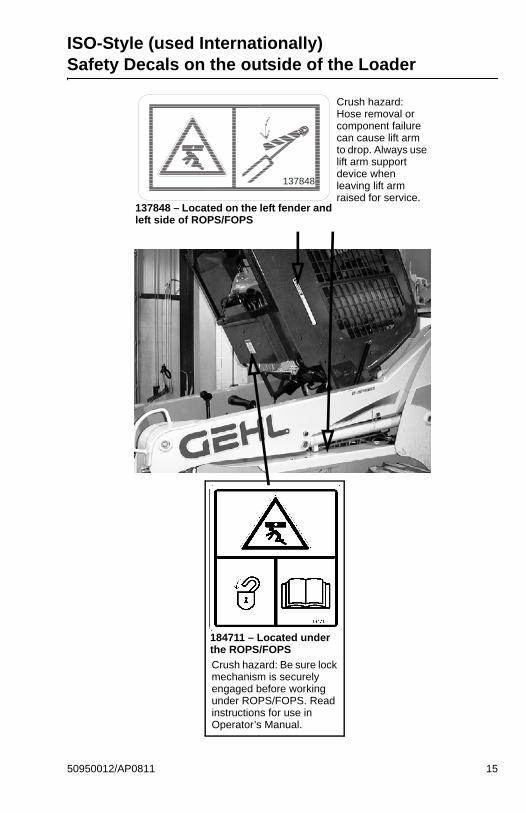
ISO-Style (used Internationally) Safety Decals on the outside of the Loader
137848 – Located on the left fender and left side of ROPS/FOPS
Crush hazard: Hose removal or component failure can cause lift arm to drop. Always use lift arm support device when leaving lift arm raised for service.
137848
184711 – Located under the ROPS/FOPS
Crush hazard: Be sure lock mechanism is securely engaged before working under ROPS/FOPS. Read instructions for use in Operator’s Manual.
50950012/AP0811 15
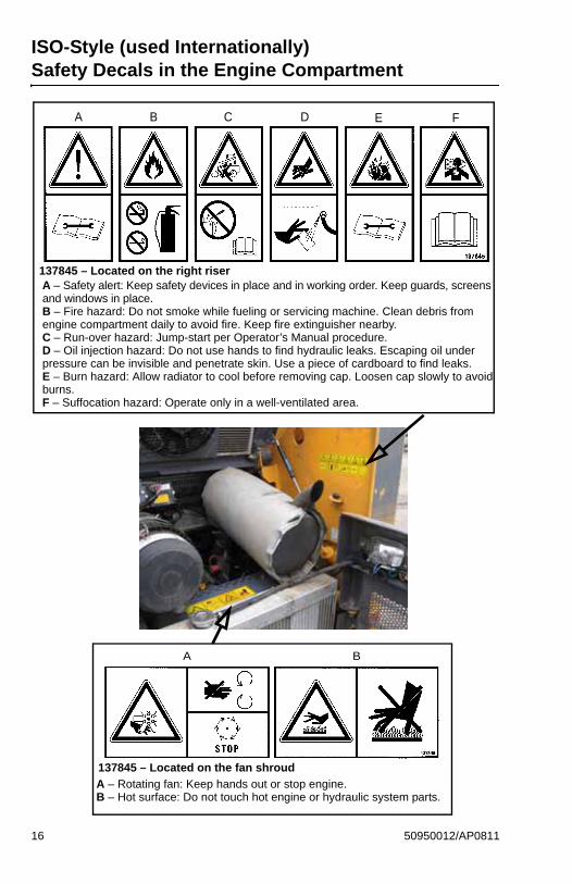
ISO-Style (used Internationally) Safety Decals in the Engine Compartment
137845 – Located on the right riserA – Safety alert: Keep safety devices in place and in working order. Keep guards, screens and windows in place.B – Fire hazard: Do not smoke while fueling or servicing machine. Clean debris from engine compartment daily to avoid fire. Keep fire extinguisher nearby.C – Run-over hazard: Jump-start per Operator’s Manual procedure.D – Oil injection hazard: Do not use hands to find hydraulic leaks. Escaping oil under pressure can be invisible and penetrate skin. Use a piece of cardboard to find leaks.E – Burn hazard: Allow radiator to cool before removing cap. Loosen cap slowly to avoid burns.F – Suffocation hazard: Operate only in a well-ventilated area.
A B C D E F
137845 – Located on the fan shroud
A – Rotating fan: Keep hands out or stop engine.B – Hot surface: Do not touch hot engine or hydraulic system parts.
A B
16 50950012/AP0811
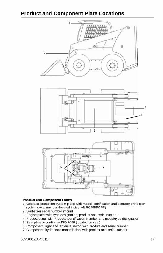
Product and Component Plate Locations
Product and Component Plates1. Operator protection system plate: with model, certification and operator protection
system serial number (located inside left ROPS/FOPS)2. Skid-steer serial number imprint3. Engine plate: with type designation, product and serial number4. Product plate: with Product Identification Number and model/type designation5. Seat plate according to ISO 7096 (located on seat)6. Component, right and left drive motor: with product and serial number7. Component, hydrostatic transmission: with product and serial number
2
1
3
4
5
6 7
50950012/AP0811 17

Notes
18 50950012/AP0811
CHAPTER 3CONTROLS AND SAFETY EQUIPMENT
Become familiar with and know how to use allsafety devices and controls on the skid-steer
loader before operating it. Know how to stop loader operationbefore starting it. This Gehl loader is designed and intended to beused only with a Gehl attachment or a Manitou Americas-approvedreferral attachment or accessory. Manitou Americas cannot beresponsible for operator safety if the loader is used with a non-approved attachment.
Guards and Shields
Whenever possible and without affecting loader operation, guards and shields areprovided to protect against potentially hazardous areas. In many places, safetydecals are also provided to warn of potential hazards and/or to display specialoperating procedures.
Read and thoroughly understand all safetydecals on the loader before operating it. Do
not operate the loader unless all factory-installed guards andshields are properly secured in place.
Operator Restraint Bar
Lower the restraint bar after entering the operator’s compartment. The restraintbar is securely anchored to the ROPS/FOPS. The restraint bar switch and the seatswitch form an interlock for the lift arm, tilt, drive and starter circuits (refer to theSafety Interlock System topic on page 20 for more information).
Never defeat the operator restraint bar or seatswitch electrically or mechanically. Always
wear the seatbelt.
WARNING
WARNING
WARNING
50950012/AP0811 19
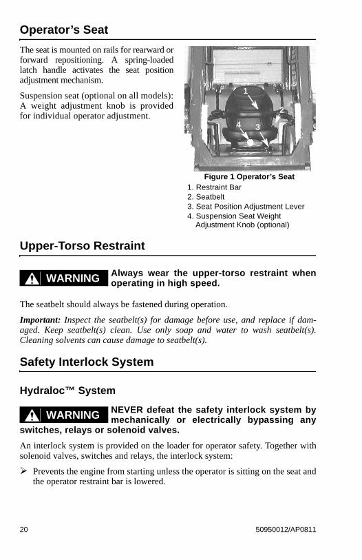
Operator’s Seat
The seat is mounted on rails for rearward orforward repositioning. A spring-loadedlatch handle activates the seat positionadjustment mechanism.
Suspension seat (optional on all models):A weight adjustment knob is providedfor individual operator adjustment.
Upper-Torso Restraint
Always wear the upper-torso restraint whenoperating in high speed.
The seatbelt should always be fastened during operation.
Important: Inspect the seatbelt(s) for damage before use, and replace if dam-aged. Keep seatbelt(s) clean. Use only soap and water to wash seatbelt(s).Cleaning solvents can cause damage to seatbelt(s).
Safety Interlock System
Hydraloc™ System
NEVER defeat the safety interlock system bymechanically or electrically bypassing any
switches, relays or solenoid valves.
An interlock system is provided on the loader for operator safety. Together withsolenoid valves, switches and relays, the interlock system:
Prevents the engine from starting unless the operator is sitting on the seat andthe operator restraint bar is lowered.
1
2
34
Figure 1 Operator’s Seat1. Restraint Bar2. Seatbelt3. Seat Position Adjustment Lever4. Suspension Seat Weight
Adjustment Knob (optional)
WARNING
WARNING
20 50950012/AP0811
Disables the lift arm, auxiliary hydraulics, attachment tilt and wheel driveswhenever the operator leaves the seat, turns the keyswitch to Off or raises therestraint bar.
Testing the Safety Interlock SystemBefore exiting the machine, check the safety interlock system for proper operation:
Restraint BarWith the engine running, raise the restraint bar. Test each of the controls. Thereshould be no more than a slight movement of the lift arm, hitch and machine. Ifthere is any significant movement, troubleshoot and correct the problem immedi-ately. Contact your dealer if necessary.
Seat SwitchWith the engine off and the restraint bar lowered, unfasten the seatbelt, and liftyour weight off the seat. Try to start the engine. If the engine starts, turn off theengine, troubleshoot and correct the problem. Contact your dealer if necessary.
ROPS/FOPS
The ROPS/FOPS (Roll-Over/Falling Object Protective Structure) is designed toprovide protection for the operator from falling objects and in case the loader tipsor rolls over, provided the operator is secured inside the ROPS/FOPS by the seat-belt and restraint bar.
Never operate the loader with the ROPS/FOPSremoved or locked back.
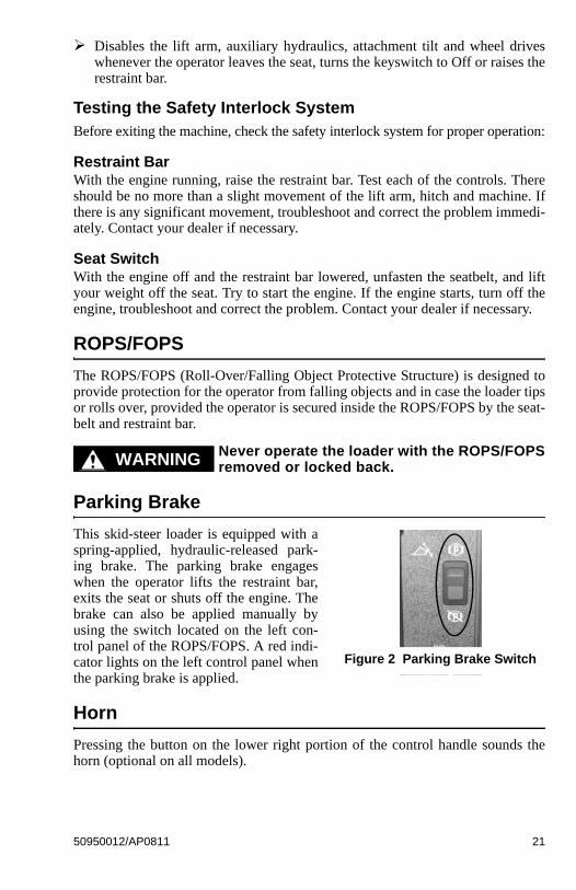
Parking Brake
This skid-steer loader is equipped with aspring-applied, hydraulic-released park-ing brake. The parking brake engageswhen the operator lifts the restraint bar,exits the seat or shuts off the engine. Thebrake can also be applied manually byusing the switch located on the left con-trol panel of the ROPS/FOPS. A red indi-cator lights on the left control panel whenthe parking brake is applied.
Horn
Pressing the button on the lower right portion of the control handle sounds thehorn (optional on all models).
WARNING
Figure 2 Parking Brake Switch
50950012/AP0811 21
Rear Window Emergency Exit
The ROPS/FOPS rear window has three functions: noise reduction, flyingobjects barrier and emergency exit.
To use the emergency exit, pull on the yellow warning tag at the top of thewindow and remove the seal. Push or kick out the window and exit.
See your local automotive glass specialist to reinstall the window.
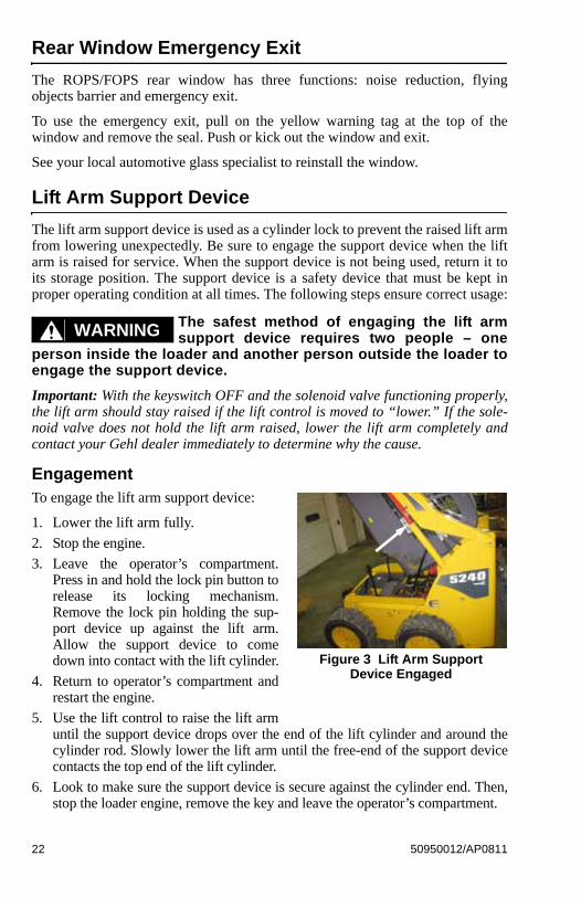
Lift Arm Support Device
The lift arm support device is used as a cylinder lock to prevent the raised lift armfrom lowering unexpectedly. Be sure to engage the support device when the liftarm is raised for service. When the support device is not being used, return it toits storage position. The support device is a safety device that must be kept inproper operating condition at all times. The following steps ensure correct usage:
The safest method of engaging the lift armsupport device requires two people – one
person inside the loader and another person outside the loader toengage the support device.
Important: With the keyswitch OFF and the solenoid valve functioning properly,the lift arm should stay raised if the lift control is moved to “lower.” If the sole-noid valve does not hold the lift arm raised, lower the lift arm completely andcontact your Gehl dealer immediately to determine why the cause.
EngagementTo engage the lift arm support device:
1. Lower the lift arm fully.
2. Stop the engine.
3. Leave the operator’s compartment.Press in and hold the lock pin button torelease its locking mechanism.Remove the lock pin holding the sup-port device up against the lift arm.Allow the support device to comedown into contact with the lift cylinder.
4. Return to operator’s compartment andrestart the engine.
5. Use the lift control to raise the lift armuntil the support device drops over the end of the lift cylinder and around thecylinder rod. Slowly lower the lift arm until the free-end of the support devicecontacts the top end of the lift cylinder.
6. Look to make sure the support device is secure against the cylinder end. Then,stop the loader engine, remove the key and leave the operator’s compartment.
WARNING
Figure 3 Lift Arm Support Device Engaged
22 50950012/AP0811
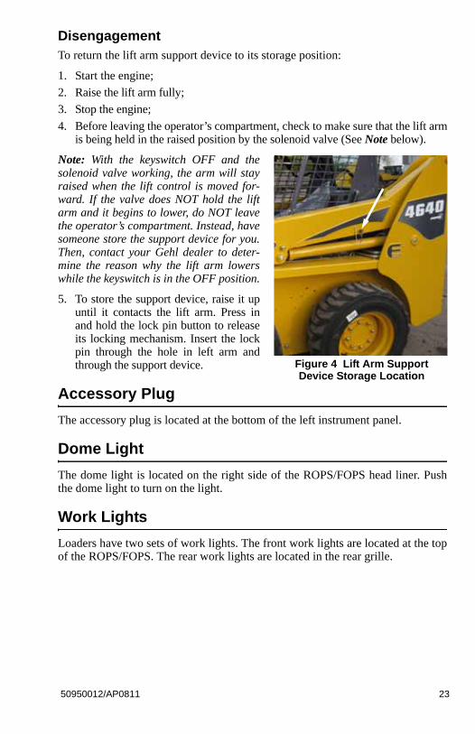
DisengagementTo return the lift arm support device to its storage position:
1. Start the engine;
2. Raise the lift arm fully;
3. Stop the engine;
4. Before leaving the operator’s compartment, check to make sure that the lift armis being held in the raised position by the solenoid valve (See Note below).
Note: With the keyswitch OFF and thesolenoid valve working, the arm will stayraised when the lift control is moved for-ward. If the valve does NOT hold the liftarm and it begins to lower, do NOT leavethe operator’s compartment. Instead, havesomeone store the support device for you.Then, contact your Gehl dealer to deter-mine the reason why the lift arm lowerswhile the keyswitch is in the OFF position.
5. To store the support device, raise it upuntil it contacts the lift arm. Press inand hold the lock pin button to releaseits locking mechanism. Insert the lockpin through the hole in left arm andthrough the support device.
Accessory Plug
The accessory plug is located at the bottom of the left instrument panel.
Dome Light
The dome light is located on the right side of the ROPS/FOPS head liner. Pushthe dome light to turn on the light.
Work Lights
Loaders have two sets of work lights. The front work lights are located at the topof the ROPS/FOPS. The rear work lights are located in the rear grille.
Figure 4 Lift Arm Support Device Storage Location
50950012/AP0811 23
Heater (optional)
Loaders with the optional heater have a dial on the left instrument panel to con-trol the fan speed.
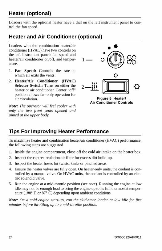
Heater and Air Conditioner (optional)
Loaders with the combination heater/airconditioner (HVAC) have two controls onthe left instrument panel: fan speed andheater/air conditioner on/off, and temper-ature.
1. Fan Speed: Controls the rate atwhich air exits the vents.
2. Heater/Air Conditioner (HVAC)Selector Switch: Turns on either theheater or air conditioner. Center “off”position allows fan-only operation forair circulation.
Note: The operator will feel cooler withonly the two front vents opened andaimed at the upper body.
Tips For Improving Heater Performance
To maximize heater and combination heater/air conditioner (HVAC) performance,the following steps are suggested.
1. Inside the engine compartment, close off the cold air intake on the heater box.
2. Inspect the cab recirculation air filter for excess dirt build-up.
3. Inspect the heater hoses for twists, kinks or pinched areas.
4. Ensure the heater valves are fully open. On heater-only units, the coolant is con-trolled by a manual valve. On HVAC units, the coolant is controlled by an elec-tric solenoid valve.
5. Run the engine at a mid-throttle position (see note). Running the engine at lowidle may not be enough load to bring the engine up to its full thermostat temper-ature (188° F, or 87° C) depending upon ambient conditions.
Note: On a cold engine start-up, run the skid-steer loader at low idle for fiveminutes before throttling up to a mid-throttle position.
Figure 5 Heater/Air Conditioner Controls
2
1
24 50950012/AP0811
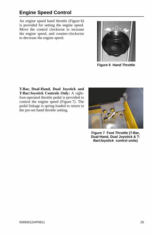
Engine Speed Control
An engine speed hand throttle (Figure 6)is provided for setting the engine speed.Move the control clockwise to increasethe engine speed, and counter-clockwiseto decrease the engine speed.
T-Bar, Dual-Hand, Dual Joystick andT-Bar/Joystick Controls Only: A right-foot-operated throttle pedal is provided tocontrol the engine speed (Figure 7). Thepedal linkage is spring-loaded to return tothe pre-set hand throttle setting.
Figure 6 Hand Throttle
Figure 7 Foot Throttle (T-Bar, Dual-Hand, Dual Joystick & T-
Bar/Joystick control units)
50950012/AP0811 25
Two-Speed Transmission (optional)
Loaders with the optional two-speed transmission use the left button on the leftcontrol handle for shifting between High (H) and Low (L). Shifting to Highallows the machine to exceed 8 mph (13 km/h), up to a maximum speed of12.4 mph (20 km/h).
Hydraglide™ Ride Control System (optional)
Loaders with the optional ride control feature have a button on the right controlhandle for shifting between normal mode and ride control mode. The ride controlsystem provides a smoother ride over uneven surfaces. Press the button once to acti-vate the system and again to deactivate. The ride control system is automaticallydeactivated when the machine is shut off.
When hydraglide is activated, the lift arm maydrop slightly without a load or several inches
with a heavy load.
Auto-Shutdown System
The auto-shutdown system will activate if the loader has an over-temperature sit-uation or no oil pressure for more than 30 seconds. An audible alarm will soundand the Engine Coolant Temperature light or Engine Oil Pressure light will turnon and the loader will shut down after approximately 30 seconds.
WARNING
26 50950012/AP0811
Attachment Mounting
The skid-steer loader is equipped with either the standard manual All-Tach®hitch or the optional Power-A-Tach® hitch for mounting a bucket and otherattachments.
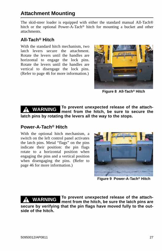
All-Tach® HitchWith the standard hitch mechanism, twolatch levers secure the attachment.Rotate the levers until the handles arehorizontal to engage the lock pins.Rotate the levers until the handles arevertical to disengage the lock pins.(Refer to page 46 for more information.)
To prevent unexpected release of the attach-ment from the hitch, be sure to secure the
latch pins by rotating the levers all the way to the stops.
Power-A-Tach® HitchWith the optional hitch mechanism, aswitch on the left control panel activatesthe latch pins. Metal “flags” on the pinsindicate their position: the pin flagsrotate to a horizontal position whenengaging the pins and a vertical positionwhen disengaging the pins. (Refer topage 46 for more information.)
To prevent unexpected release of the attach-ment from the hitch, be sure the latch pins are
secure by verifying that the pin flags have moved fully to the out-side of the hitch.
Figure 8 All-Tach® Hitch
WARNING
Figure 9 Power-A-Tach® Hitch
WARNING
50950012/AP0811 27
Instrument Panels
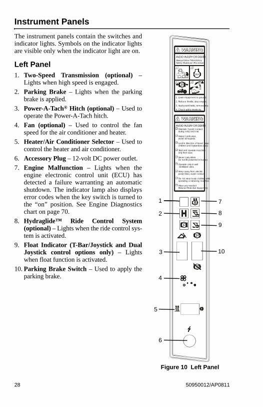
The instrument panels contain the switches andindicator lights. Symbols on the indicator lightsare visible only when the indicator light are on.
Left Panel1. Two-Speed Transmission (optional) –
Lights when high speed is engaged.
2. Parking Brake – Lights when the parkingbrake is applied.
3. Power-A-Tach® Hitch (optional) – Used tooperate the Power-A-Tach hitch.
4. Fan (optional) – Used to control the fanspeed for the air conditioner and heater.
5. Heater/Air Conditioner Selector – Used tocontrol the heater and air conditioner.
6. Accessory Plug – 12-volt DC power outlet.
7. Engine Malfunction – Lights when theengine electronic control unit (ECU) hasdetected a failure warranting an automaticshutdown. The indicator lamp also displayserror codes when the key switch is turned tothe “on” position. See Engine Diagnosticschart on page 70.
8. Hydraglide™ Ride Control System(optional) – Lights when the ride control sys-tem is activated.
9. Float Indicator (T-Bar/Joystick and DualJoystick control options only) – Lightswhen float function is activated.
10. Parking Brake Switch – Used to apply theparking brake.
P
P
Always follow "MandatorySafety Shutdown Procedure".
STOP
AVOID INJURY OR DEATH
P
Maintain 3-point contact during entry and exit.
Inspect work area, avoid all hazards.
Look in direction of travel. Keep children and bystanders away.
Start and operate machine only from seat.
Never carry riders. Do not lift personnel in bucket.
Operate only in well ventilated area.
Keep away from electric power lines, avoid contact.
Do not wear loose clothing while operating or servicing machine.
Wear any needed Personal Protective Equipment.
AVOID INJURY OR DEATH
1 2
3 4
1. Lower equipment to ground.
2. Reduce throttle, stop engine.
3. Apply park brake; remove key.
4. Check safety interlocks.
P
Figure 10 Left Panel
1
2
3
4
5
6
7
8
9
10
28 50950012/AP0811
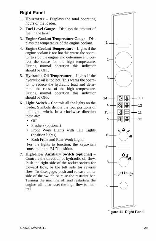
Right Panel1. Hourmeter – Displays the total operating
hours of the loader.
2. Fuel Level Gauge – Displays the amount offuel in the tank.
3. Engine Coolant Temperature Gauge – Dis-plays the temperature of the engine coolant.
4. Engine Coolant Temperature – Lights if theengine coolant is too hot this warns the opera-tor to stop the engine and determine and cor-rect the cause for the high temperature.During normal operation this indicatorshould be OFF.
5. Hydraulic Oil Temperature – Lights if thehydraulic oil is too hot. This warns the opera-tor to reduce the hydraulic load and deter-mine the cause of the high temperature.During normal operation this indicatorshould be OFF.
6. Light Switch – Controls all the lights on theloader. Symbols denote the four positions ofthe light switch. In a clockwise directionthese are: • Off• Flashers (optional)• Front Work Lights with Tail Lights
(position lights)• Both Front and Rear Work LightsFor the lights to function, the keyswitchmust be in the RUN position.
7. High-Flow Auxiliary Switch (optional) –Controls the direction of hydraulic oil flow.Push the right side of the rocker switch forforward flow, or the left side for reverseflow. To disengage, push and release eitherside of the switch or raise the restraint bar.Turning the machine off and restarting theengine will also reset the high-flow to neu-tral.
1
2
3
4
5
6
7
9
10
12
13
Figure 11 Right Panel
8
11
14
15
50950012/AP0811 29

8. Keyswitch – In a clockwise rotation, these positions are:• OFF Position – With the key vertical, power from the battery is discon-
nected from the controls and instrument panel electrical circuits. This isthe only position the key can be inserted or removed from the keyswitch.
• ON (or RUN) Position – With the key turned one position clockwise fromvertical, power from the battery is supplied to all control and instrumentpanel circuits.
• START Position – With the key turned fully clockwise, the electricstarter energizes, start the engine. Release the key to RUN position afterthe engine starts.
Note: The engine cannot be started unless the operator is sitting in the seat andthe restraint bar is lowered.
9. Engine Speed Control – Controls the engine speed. Move the control clock-wise to increase and counter-clockwise to decrease the engine speed.
10. Fasten Seatbelt – A momentary visual (and audible) indicator to remind theoperator to fasten the seatbelt(s).
11. Battery – Lights if the charging voltage is too high or too low. During normaloperation this indicator should be OFF.
12. Preheat Indicator Lamp – Lights when the (automatic) preheat is active.During normal operation this indicator should be OFF.
13. Engine Oil Pressure – Lights if the engine oil pressure is too low. Warns theoperator to immediately stop the engine and determine the cause for the lowpressure. During normal operation this indicator should be OFF.
14. Engine Air Restriction Indicator (optional) - Lights when a restriction inthe engine air filter is detected. Warns the operator to immediately stop theengine and clean or replace the element in the engine air cleaner. During nor-mal operation this indicator should be OFF.
15. Hydraulic Oil Filter Indicator (optional) - Lights if the hydraulic oil filterbecomes restricted. Warns the operator to immediately stop the engine, allowthe engine to cool, and then change the oil and filter. During normal operationthis indicator should be OFF.
30 50950012/AP0811
T-Bar Controls
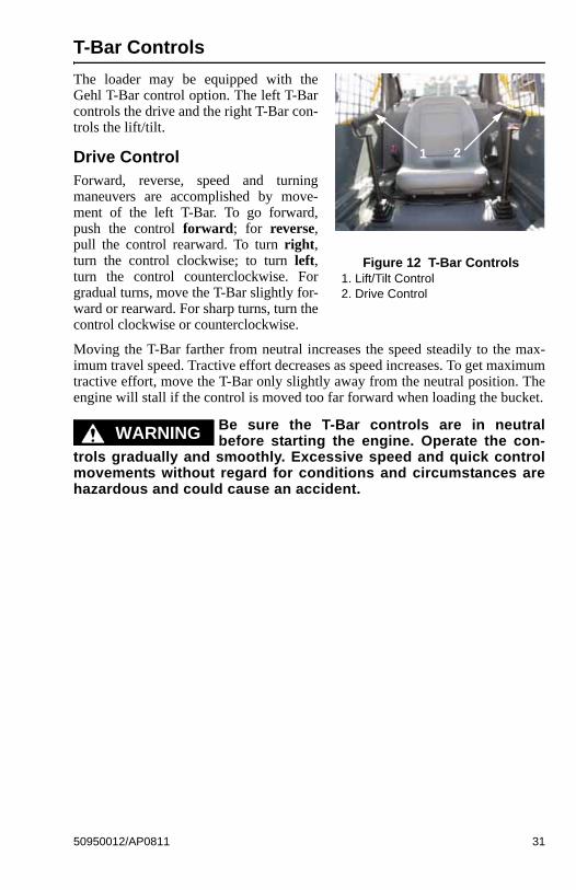
The loader may be equipped with theGehl T-Bar control option. The left T-Barcontrols the drive and the right T-Bar con-trols the lift/tilt.
Drive ControlForward, reverse, speed and turningmaneuvers are accomplished by move-ment of the left T-Bar. To go forward,push the control forward; for reverse,pull the control rearward. To turn right,turn the control clockwise; to turn left,turn the control counterclockwise. Forgradual turns, move the T-Bar slightly for-ward or rearward. For sharp turns, turn thecontrol clockwise or counterclockwise.
Moving the T-Bar farther from neutral increases the speed steadily to the max-imum travel speed. Tractive effort decreases as speed increases. To get maximumtractive effort, move the T-Bar only slightly away from the neutral position. Theengine will stall if the control is moved too far forward when loading the bucket.
Be sure the T-Bar controls are in neutralbefore starting the engine. Operate the con-
trols gradually and smoothly. Excessive speed and quick controlmovements without regard for conditions and circumstances arehazardous and could cause an accident.
Figure 12 T-Bar Controls1. Lift/Tilt Control2. Drive Control
1 2
WARNING
50950012/AP0811 31

Lift/Tilt ControlMoving the lift arm and tilting the attachment are accomplished by movement ofthe right T-Bar. To raise the lift arm, pull the control straight rearward; to lowerthe lift arm, push the control straight forward. To tilt the attachment forwardand down, twist the control clockwise; to tilt the attachment up and back,twist the control counterclockwise.
Note: The speed of the lift/tilt motion is directly proportional to the amount ofT-Bar movement and engine speed.
To place the lift arm into the detent (“float”) position, push the right T-Bar all theway forward. This position allows the lowered lift arm to float while travelingover changing ground conditions.
Never push the lift/tilt T-Bar control into the“float” position with the attachment loaded or
raised, because this will cause the lift arm to lower very rapidly.
WARNING
32 50950012/AP0811
T-Bar/Joystick Controls
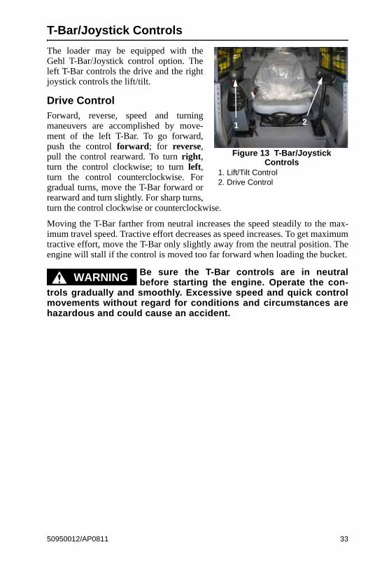
The loader may be equipped with theGehl T-Bar/Joystick control option. Theleft T-Bar controls the drive and the rightjoystick controls the lift/tilt.
Drive ControlForward, reverse, speed and turningmaneuvers are accomplished by move-ment of the left T-Bar. To go forward,push the control forward; for reverse,pull the control rearward. To turn right,turn the control clockwise; to turn left,turn the control counterclockwise. Forgradual turns, move the T-Bar forward orrearward and turn slightly. For sharp turns,turn the control clockwise or counterclockwise.
Moving the T-Bar farther from neutral increases the speed steadily to the max-imum travel speed. Tractive effort decreases as speed increases. To get maximumtractive effort, move the T-Bar only slightly away from the neutral position. Theengine will stall if the control is moved too far forward when loading the bucket.
Be sure the T-Bar controls are in neutralbefore starting the engine. Operate the con-
trols gradually and smoothly. Excessive speed and quick controlmovements without regard for conditions and circumstances arehazardous and could cause an accident.
Figure 13 T-Bar/JoystickControls
1. Lift/Tilt Control2. Drive Control
1 2
WARNING
50950012/AP0811 33
Lift/Tilt ControlMoving the lift arm and tilting the attachment are accomplished by movement ofthe right joystick. To raise the lift arm, pull the control straight rearward; tolower the lift arm, push the control straight forward. To tilt the attachment for-ward and down, move the control to the right; to tilt the attachment up andback, move the control to the left.
Note: The speed of the lift/tilt motion is directly proportional to the amount ofjoystick movement and engine speed.
To place the lift arm into the detent (“float”) position, push and hold the leftbutton on the right joystick. This mode allows the lowered lift arm to move upand down without moving the T-Bar while traveling over changing ground condi-tions. An indicator light in the left instrument panel will blink when float is acti-vated.
Never push the float control button with theattachment loaded or raised, because this will
cause the lift arm to lower very rapidly.
Releasing the float button will cancel the float mode if the button was pressedless than five seconds. If the float mode button is pressed longer than five sec-onds, the float feature will stay on and the float indicator lamp will light continu-ously until the button is pressed again.
WARNING
34 50950012/AP0811
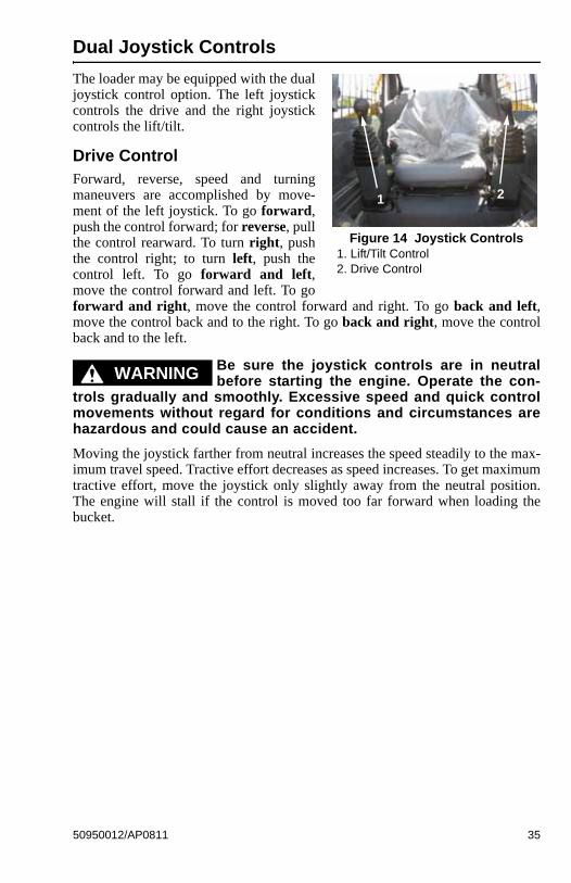
Dual Joystick Controls
The loader may be equipped with the dualjoystick control option. The left joystickcontrols the drive and the right joystickcontrols the lift/tilt.
Drive ControlForward, reverse, speed and turningmaneuvers are accomplished by move-ment of the left joystick. To go forward,push the control forward; for reverse, pullthe control rearward. To turn right, pushthe control right; to turn left, push thecontrol left. To go forward and left,move the control forward and left. To goforward and right, move the control forward and right. To go back and left,move the control back and to the right. To go back and right, move the controlback and to the left.
Be sure the joystick controls are in neutralbefore starting the engine. Operate the con-
trols gradually and smoothly. Excessive speed and quick controlmovements without regard for conditions and circumstances arehazardous and could cause an accident.
Moving the joystick farther from neutral increases the speed steadily to the max-imum travel speed. Tractive effort decreases as speed increases. To get maximumtractive effort, move the joystick only slightly away from the neutral position.The engine will stall if the control is moved too far forward when loading thebucket.
Figure 14 Joystick Controls1. Lift/Tilt Control2. Drive Control
1 2
WARNING
50950012/AP0811 35
Lift/Tilt ControlMoving the lift arm and tilting the attachment are accomplished by movement ofthe right joystick. To raise the lift arm, pull the control straight rearward; tolower the lift arm, push the control straight forward. To tilt the attachment for-ward and downward, move the control to the right; to tilt the attachment upand back, move the control to the left.
Note: The speed of the lift/tilt motion is directly proportional to the amount ofjoystick movement and engine speed.
To place the lift arm into the “float” position, push and hold the left button on theright joystick. This mode allows the lowered lift arm to follow the ground con-tour while traveling over changing ground conditions. An indicator light in theleft instrument panel will blink when the float is activated.
Never push the float control button with theattachment loaded or raised, because this will
cause the lift arm to lower very rapidly.
Releasing the float button will cancel the float mode if the button was pressedless than five seconds. If the float mode button is pressed longer than five sec-onds, the float feature will stay on and the float indicator will light continuouslyuntil the button is pressed again.
WARNING
36 50950012/AP0811
Hand/Foot Controls
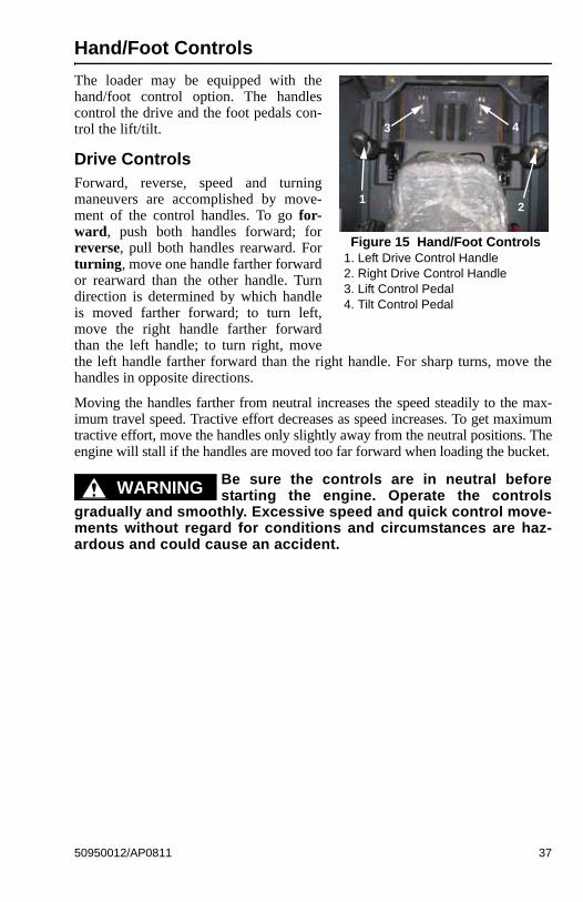
The loader may be equipped with thehand/foot control option. The handlescontrol the drive and the foot pedals con-trol the lift/tilt.
Drive ControlsForward, reverse, speed and turningmaneuvers are accomplished by move-ment of the control handles. To go for-ward, push both handles forward; forreverse, pull both handles rearward. Forturning, move one handle farther forwardor rearward than the other handle. Turndirection is determined by which handleis moved farther forward; to turn left,move the right handle farther forwardthan the left handle; to turn right, movethe left handle farther forward than the right handle. For sharp turns, move thehandles in opposite directions.
Moving the handles farther from neutral increases the speed steadily to the max-imum travel speed. Tractive effort decreases as speed increases. To get maximumtractive effort, move the handles only slightly away from the neutral positions. Theengine will stall if the handles are moved too far forward when loading the bucket.
Be sure the controls are in neutral beforestarting the engine. Operate the controls
gradually and smoothly. Excessive speed and quick control move-ments without regard for conditions and circumstances are haz-ardous and could cause an accident.
Figure 15 Hand/Foot Controls1. Left Drive Control Handle2. Right Drive Control Handle3. Lift Control Pedal4. Tilt Control Pedal
12
3 4
WARNING
50950012/AP0811 37
Lift/Tilt ControlsMoving the lift arm and tilting the attachment are accomplished by movement ofthe foot pedals. The left pedal raises and lowers the lift arm; the right pedal tiltsthe attachment. To raise the lift arm, push down on the back of the left pedal withyour left heel; to lower the lift arm, push down on the front of the left pedal withthe toes of your left foot. To tilt the attachment forward and downward, pushdown on the front of the right pedal with the toes of your right foot; to tilt theattachment up and back, push down on the back of the right pedal with yourright heel.
Note: The speed of the lift/tilt motion is directly proportional to the amount ofpedal movement and engine speed.
To place the lift arm into the detent (“float”) position, use the toes of your leftfoot to push the front of the left pedal all the way down. This position allows thelowered lift arm to follow the ground contour while traveling over changingground conditions.
Never push the left pedal into the “float” posi-tion with the attachment loaded or raised,
because this will cause the lift arm to lower very rapidly.
WARNING
38 50950012/AP0811
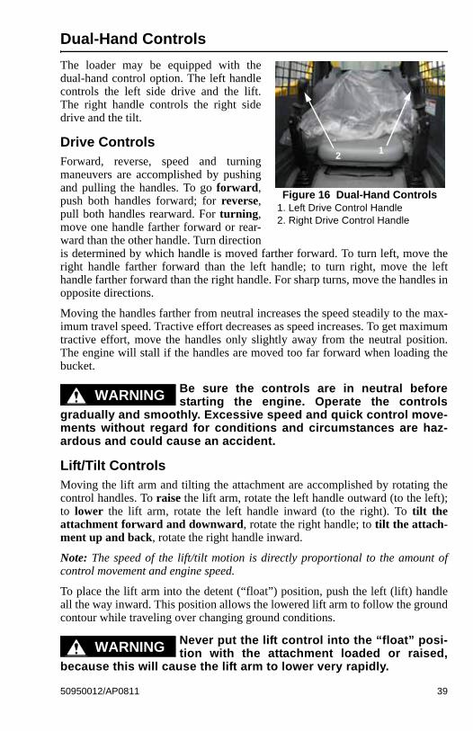
Dual-Hand Controls
The loader may be equipped with thedual-hand control option. The left handlecontrols the left side drive and the lift.The right handle controls the right sidedrive and the tilt.
Drive ControlsForward, reverse, speed and turningmaneuvers are accomplished by pushingand pulling the handles. To go forward,push both handles forward; for reverse,pull both handles rearward. For turning,move one handle farther forward or rear-ward than the other handle. Turn directionis determined by which handle is moved farther forward. To turn left, move theright handle farther forward than the left handle; to turn right, move the lefthandle farther forward than the right handle. For sharp turns, move the handles inopposite directions.
Moving the handles farther from neutral increases the speed steadily to the max-imum travel speed. Tractive effort decreases as speed increases. To get maximumtractive effort, move the handles only slightly away from the neutral position.The engine will stall if the handles are moved too far forward when loading thebucket.
Be sure the controls are in neutral beforestarting the engine. Operate the controls
gradually and smoothly. Excessive speed and quick control move-ments without regard for conditions and circumstances are haz-ardous and could cause an accident.
Lift/Tilt ControlsMoving the lift arm and tilting the attachment are accomplished by rotating thecontrol handles. To raise the lift arm, rotate the left handle outward (to the left);to lower the lift arm, rotate the left handle inward (to the right). To tilt theattachment forward and downward, rotate the right handle; to tilt the attach-ment up and back, rotate the right handle inward.
Note: The speed of the lift/tilt motion is directly proportional to the amount ofcontrol movement and engine speed.
To place the lift arm into the detent (“float”) position, push the left (lift) handleall the way inward. This position allows the lowered lift arm to follow the groundcontour while traveling over changing ground conditions.
Never put the lift control into the “float” posi-tion with the attachment loaded or raised,
because this will cause the lift arm to lower very rapidly.
Figure 16 Dual-Hand Controls1. Left Drive Control Handle2. Right Drive Control Handle
12
WARNING
WARNING
50950012/AP0811 39
Auxiliary Hydraulic Controls
Auxiliary hydraulics are used with attachments that have a mechanism requiringhydraulic power.
Always be sure the auxiliary hydraulic controlis in neutral before starting the loader or dis-
connecting the auxiliary hydraulic couplers.
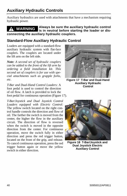
Standard-Flow Auxiliary Hydraulic ControlLoaders are equipped with a standard-flowauxiliary hydraulic system with flat-facecouplers. The couplers are located underthe lift arm on the left side.
Note: A second set of hydraulic couplerscan be added to the front of the lift arm byordering a field installation kit. Thissecond set of couplers is for use with spe-cial attachments such as grapple forks,etc.
T-Bar and Dual-Hand Control Loaders: Afoot pedal is used to control the directionof oil flow. A latch is provided to lock thefoot pedal for continuous operation (Figure 17).
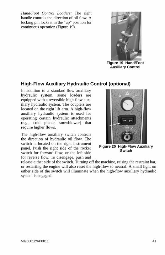
T-Bar/Joystick and Dual Joystick ControlLoaders equipped with Electric Control:The yellow switch located on the right con-trol handle controls the direction and flow ofoil. The farther the switch is moved from thecenter, the higher the flow in the auxiliarycircuit. The direction of flow is reversedwhen the switch is moved in the oppositedirection from the center. For continuousoperation, move the switch fully in eitherdirection and press the red trigger button,located on the front of the grip, and release.To cancel continuous operation, press the redtrigger button again or move the yellowswitch in either direction.
WARNING
Figure 17 T-Bar and Dual-Hand Auxiliary Hydraulic
Control
Figure 18 T-Bar/Joystick and Dual Joystick Electric
Auxiliary Control
40 50950012/AP0811
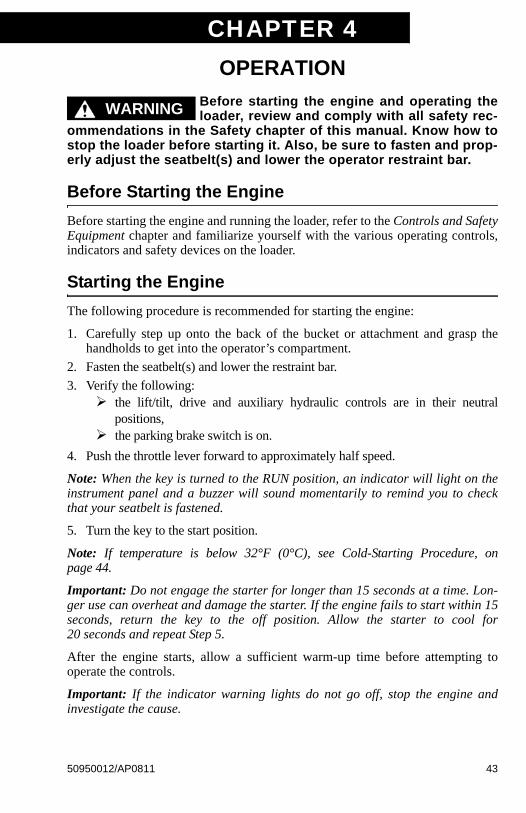
Hand/Foot Control Loaders: The righthandle controls the direction of oil flow. Alocking pin locks it in the “up” position forcontinuous operation (Figure 19).
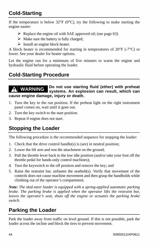
High-Flow Auxiliary Hydraulic Control (optional)In addition to a standard-flow auxiliaryhydraulic system, some loaders areequipped with a reversible high-flow aux-iliary hydraulic system. The couplers arelocated on the right lift arm. A high-flowauxiliary hydraulic system is used foroperating certain hydraulic attachments(e.g., cold planer, snowblower) thatrequire higher flows.
The high-flow auxiliary switch controlsthe direction of hydraulic oil flow. Theswitch is located on the right instrumentpanel. Push the right side of the rockerswitch for forward flow, or the left sidefor reverse flow. To disengage, push andrelease either side of the switch. Turning off the machine, raising the restraint bar,or restarting the engine will also reset the high-flow to neutral. A small light oneither side of the switch will illuminate when the high-flow auxiliary hydraulicsystem is engaged.
Figure 19 Hand/Foot Auxiliary Control
Figure 20 High-Flow Auxiliary Switch
50950012/AP0811 41

42 50950012/AP0811
Notes
CHAPTER 4OPERATION
Before starting the engine and operating theloader, review and comply with all safety rec-
ommendations in the Safety chapter of this manual. Know how tostop the loader before starting it. Also, be sure to fasten and prop-erly adjust the seatbelt(s) and lower the operator restraint bar.
Before Starting the Engine
Before starting the engine and running the loader, refer to the Controls and SafetyEquipment chapter and familiarize yourself with the various operating controls,indicators and safety devices on the loader.
Starting the Engine
The following procedure is recommended for starting the engine:
1. Carefully step up onto the back of the bucket or attachment and grasp thehandholds to get into the operator’s compartment.
2. Fasten the seatbelt(s) and lower the restraint bar.
3. Verify the following: the lift/tilt, drive and auxiliary hydraulic controls are in their neutral
positions, the parking brake switch is on.
4. Push the throttle lever forward to approximately half speed.
Note: When the key is turned to the RUN position, an indicator will light on theinstrument panel and a buzzer will sound momentarily to remind you to checkthat your seatbelt is fastened.
5. Turn the key to the start position.
Note: If temperature is below 32°F (0°C), see Cold-Starting Procedure, onpage 44.
Important: Do not engage the starter for longer than 15 seconds at a time. Lon-ger use can overheat and damage the starter. If the engine fails to start within 15seconds, return the key to the off position. Allow the starter to cool for20 seconds and repeat Step 5.
After the engine starts, allow a sufficient warm-up time before attempting tooperate the controls.
Important: If the indicator warning lights do not go off, stop the engine andinvestigate the cause.
WARNING
50950012/AP0811 43
Cold-Starting
If the temperature is below 32°F (0°C), try the following to make starting theengine easier:
Replace the engine oil with SAE approved oil; (see page 63) Make sure the battery is fully charged; Install an engine block heater.
A block heater is recommended for starting in temperatures of 20°F (-7°C) orlower. See your dealer for heater options.
Let the engine run for a minimum of five minutes to warm the engine andhydraulic fluid before operating the loader.
Cold-Starting Procedure
Do not use starting fluid (ether) with preheatsystems. An explosion can result, which can
cause engine damage, injury or death.
1. Turn the key to the run position. If the preheat light on the right instrumentpanel comes on, wait until it goes out.
2. Turn the key switch to the start position.
3. Repeat if engine does not start.
Stopping the Loader
The following procedure is the recommended sequence for stopping the loader:
1. Check that the drive control handle(s) is (are) in neutral position;
2. Lower the lift arm and rest the attachment on the ground;
3. Pull the throttle lever back to the low idle position (and/or take your foot off thethrottle pedal for hands-only control machines);
4. Turn the keyswitch to the off position and remove the key; and
5. Raise the restraint bar, unfasten the seatbelt(s). Verify that movement of thecontrols does not cause machine movement and then grasp the handholds whileclimbing out of the operator’s compartment.
Note: The skid-steer loader is equipped with a spring-applied automatic parkingbrake. The parking brake is applied when the operator lifts the restraint bar,leaves the operator’s seat, shuts off the engine or actuates the parking brakeswitch.
Parking the Loader
Park the loader away from traffic on level ground. If this is not possible, park theloader across the incline and block the tires to prevent movement.
WARNING
44 50950012/AP0811
Jump-starting
If the battery becomes discharged or does not have enough power to start theengine, use jumper cables and the following procedure to jump-start the loaderengine.
The ONLY safe method for jump-starting adischarged battery is for TWO PEOPLE to
perform the following procedure. The second person removes thejumper cables so that the operator does not have to leave theoperator’s compartment with the engine running. NEVER makejumper cable connections directly to the starter solenoid of eitherengine. DO NOT start the engine from any position other than onthe operator’s seat and then ONLY after being sure ALL controlsare in “neutral.”
Closely follow the procedure, in order, to avoid personal injury. Inaddition, wear safety glasses to protect your eyes and avoidleaning over the batteries while jump-starting.
DO NOT jump-start the battery if it is frozen, because it may rupture or explode.
Note: BE SURE the jumper battery is a 12-volt D.C. battery.
1. Turn the keyswitches of both vehicles to OFF, be sure the vehicles are in“neutral” and NOT touching each other.
2. Connect the positive (+) jumper cable to the positive (+) battery terminal on thedisabled loader first. DO NOT allow the positive clamps to touch any metalother than the positive (+) battery terminals.
3. Connect the other end of the positive jumper cable to the jumper vehicle’s bat-tery positive (+) terminal.
4. Connect the negative (-) jumper cable to the jumper vehicle’s battery negative(-) terminal.
5. Make the final negative (-) jumper cable connection to the disabled loader’sengine block or loader frame (ground) – NOT to the disabled battery’s negativepost. If connected to the engine, keep the jumper clamp away from the battery,fuel lines and moving parts.
6. Start the loader. If it does not start at once, start the jumper vehicle engine toavoid excessive drain on the booster battery.
7. After the disabled loader is started and running smoothly, have the second per-son remove the jumper cables (negative [-] jumper cable first) from the jumpervehicle’s battery and then from the disabled loader while being sure NOT toshort the two cables together.
Allow sufficient time for the skid-steer loader alternator to build-up a charge inthe battery before attempting to operate the loader or shut the engine off.
WARNING
50950012/AP0811 45
Changing Attachments
To prevent unexpected release of the attach-ment from the hitch, be sure to properly
secure the hitch latch pins by rotating the latch leversfully(manual All-Tach® hitch) or by ensuring that the pin flags areall the way to the outside (Power-A-Tach® hitch).
The skid-steer loader features either a manual or a power hitch for mounting abucket or other attachment conforming to SAE Standard J2513.
On a manual All-Tach® hitch (Figure 21), two latch levers engage the latch pinsto secure the attachment. On a Power-A-Tach® hitch (Figure 22), a switch on theleft instrument panel (page 28) activates the latch pins to secure the attachment.
Connecting Attachments
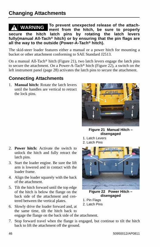
1. Manual hitch: Rotate the latch leversuntil the handles are vertical to retractthe lock pins.
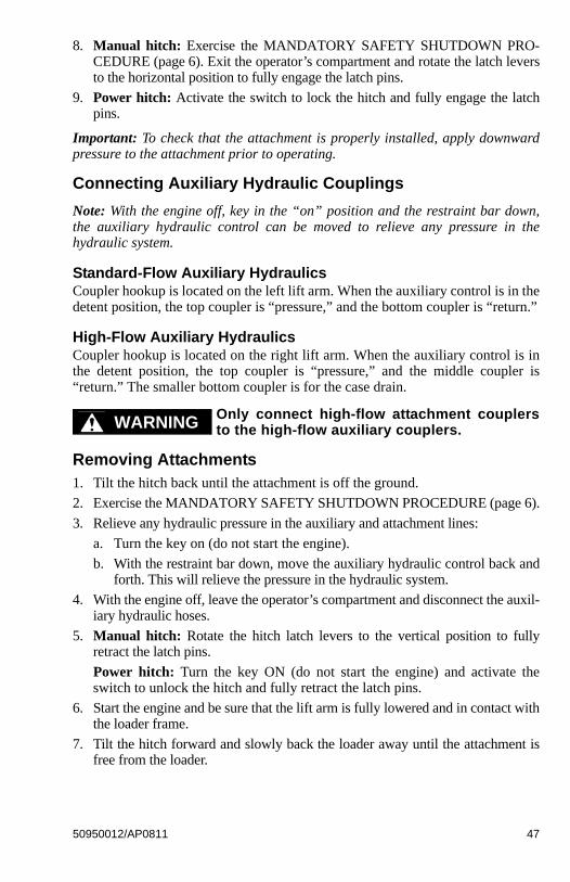
2. Power hitch: Activate the switch tounlock the hitch and fully retract thelatch pins.
3. Start the loader engine. Be sure the liftarm is lowered and in contact with theloader frame.
4. Align the loader squarely with the backof the attachment.
5. Tilt the hitch forward until the top edgeof the hitch is below the flange on theback side of the attachment and cen-tered between the vertical plates.
6. Slowly drive the loader forward and, atthe same time, tilt the hitch back toengage the flange on the back side of the attachment.
7. Stop forward travel when the flange is engaged, but continue to tilt the hitchback to lift the attachment off the ground.
WARNING
Figure 21 Manual Hitch – disengaged
1. Latch Levers2. Latch Pins
1 1
2 2
Figure 22 Power Hitch – disengaged
1. Pin Flags2. Latch Pins
1
12 21
46 50950012/AP0811
8. Manual hitch: Exercise the MANDATORY SAFETY SHUTDOWN PRO-CEDURE (page 6). Exit the operator’s compartment and rotate the latch leversto the horizontal position to fully engage the latch pins.
9. Power hitch: Activate the switch to lock the hitch and fully engage the latchpins.
Important: To check that the attachment is properly installed, apply downwardpressure to the attachment prior to operating.
Connecting Auxiliary Hydraulic Couplings
Note: With the engine off, key in the “on” position and the restraint bar down,the auxiliary hydraulic control can be moved to relieve any pressure in thehydraulic system.
Standard-Flow Auxiliary HydraulicsCoupler hookup is located on the left lift arm. When the auxiliary control is in thedetent position, the top coupler is “pressure,” and the bottom coupler is “return.”
High-Flow Auxiliary HydraulicsCoupler hookup is located on the right lift arm. When the auxiliary control is inthe detent position, the top coupler is “pressure,” and the middle coupler is“return.” The smaller bottom coupler is for the case drain.
Only connect high-flow attachment couplersto the high-flow auxiliary couplers.
Removing Attachments1. Tilt the hitch back until the attachment is off the ground.
2. Exercise the MANDATORY SAFETY SHUTDOWN PROCEDURE (page 6).
3. Relieve any hydraulic pressure in the auxiliary and attachment lines:
a. Turn the key on (do not start the engine).
b. With the restraint bar down, move the auxiliary hydraulic control back andforth. This will relieve the pressure in the hydraulic system.
4. With the engine off, leave the operator’s compartment and disconnect the auxil-iary hydraulic hoses.
5. Manual hitch: Rotate the hitch latch levers to the vertical position to fullyretract the latch pins.
Power hitch: Turn the key ON (do not start the engine) and activate theswitch to unlock the hitch and fully retract the latch pins.
6. Start the engine and be sure that the lift arm is fully lowered and in contact withthe loader frame.
7. Tilt the hitch forward and slowly back the loader away until the attachment isfree from the loader.
WARNING
50950012/AP0811 47
Self-Leveling
The feature is intended to automatically keep the attachment level while the liftarm is being raised.
Using a Bucket
Always maintain a safe distance from electricpower lines and avoid contact with any elec-
trically charged conductor or gas line. Accidental contact or rup-ture can result in electrocution or an explosion. Contact the“Digger’s Hotline” or proper local authorities for utility line loca-tions before starting to dig.
Driving over Rough TerrainWhen traveling over rough terrain, drive slowly with the bucket lowered.
Driving on an InclineWhen traveling on an incline, travel with the heavy end pointing uphill.
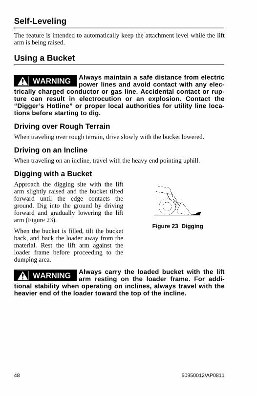
Digging with a BucketApproach the digging site with the liftarm slightly raised and the bucket tiltedforward until the edge contacts theground. Dig into the ground by drivingforward and gradually lowering the liftarm (Figure 23).
When the bucket is filled, tilt the bucketback, and back the loader away from thematerial. Rest the lift arm against theloader frame before proceeding to thedumping area.
Always carry the loaded bucket with the liftarm resting on the loader frame. For addi-
tional stability when operating on inclines, always travel with theheavier end of the loader toward the top of the incline.
WARNING
Figure 23 Digging
WARNING
48 50950012/AP0811
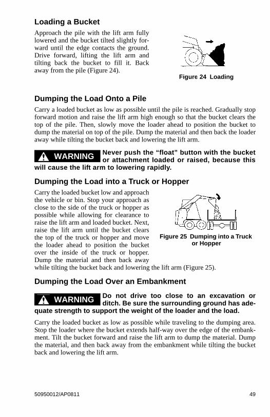
Loading a BucketApproach the pile with the lift arm fullylowered and the bucket tilted slightly for-ward until the edge contacts the ground.Drive forward, lifting the lift arm andtilting back the bucket to fill it. Backaway from the pile (Figure 24).
Dumping the Load Onto a PileCarry a loaded bucket as low as possible until the pile is reached. Gradually stopforward motion and raise the lift arm high enough so that the bucket clears thetop of the pile. Then, slowly move the loader ahead to position the bucket todump the material on top of the pile. Dump the material and then back the loaderaway while tilting the bucket back and lowering the lift arm.
Never push the “float” button with the bucketor attachment loaded or raised, because this
will cause the lift arm to lowering rapidly.
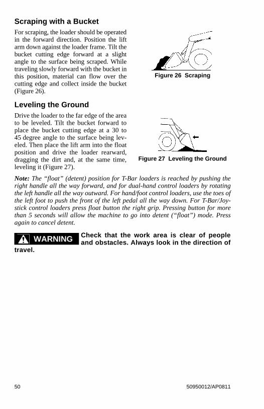
Dumping the Load into a Truck or HopperCarry the loaded bucket low and approachthe vehicle or bin. Stop your approach asclose to the side of the truck or hopper aspossible while allowing for clearance toraise the lift arm and loaded bucket. Next,raise the lift arm until the bucket clearsthe top of the truck or hopper and movethe loader ahead to position the bucketover the inside of the truck or hopper.Dump the material and then back awaywhile tilting the bucket back and lowering the lift arm (Figure 25).
Dumping the Load Over an Embankment
Do not drive too close to an excavation orditch. Be sure the surrounding ground has ade-
quate strength to support the weight of the loader and the load.
Carry the loaded bucket as low as possible while traveling to the dumping area.Stop the loader where the bucket extends half-way over the edge of the embank-ment. Tilt the bucket forward and raise the lift arm to dump the material. Dumpthe material, and then back away from the embankment while tilting the bucketback and lowering the lift arm.
Figure 24 Loading
WARNING
Figure 25 Dumping into a Truck or Hopper
WARNING
50950012/AP0811 49
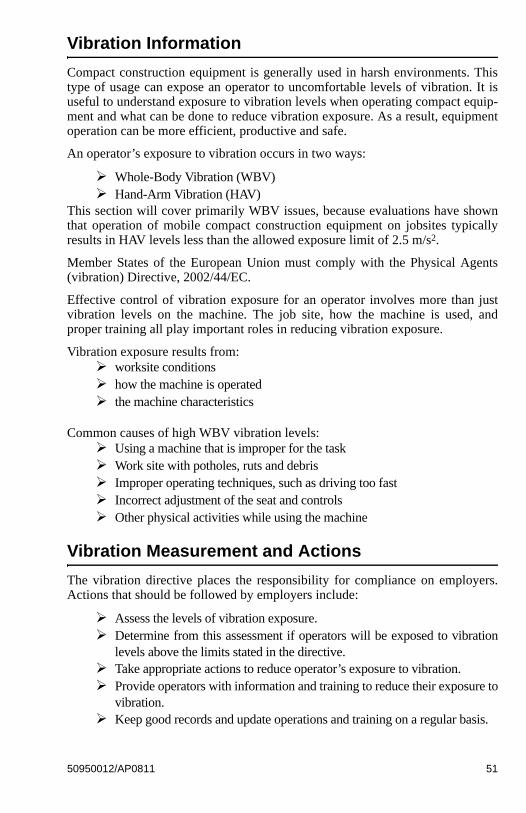
Scraping with a BucketFor scraping, the loader should be operatedin the forward direction. Position the liftarm down against the loader frame. Tilt thebucket cutting edge forward at a slightangle to the surface being scraped. Whiletraveling slowly forward with the bucket inthis position, material can flow over thecutting edge and collect inside the bucket(Figure 26).
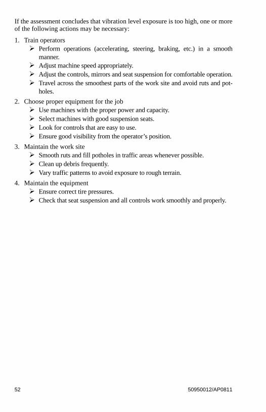
Leveling the GroundDrive the loader to the far edge of the areato be leveled. Tilt the bucket forward toplace the bucket cutting edge at a 30 to45 degree angle to the surface being lev-eled. Then place the lift arm into the floatposition and drive the loader rearward,dragging the dirt and, at the same time,leveling it (Figure 27).
Note: The “float” (detent) position for T-Bar loaders is reached by pushing theright handle all the way forward, and for dual-hand control loaders by rotatingthe left handle all the way outward. For hand/foot control loaders, use the toes ofthe left foot to push the front of the left pedal all the way down. For T-Bar/Joy-stick control loaders press float button the right grip. Pressing button for morethan 5 seconds will allow the machine to go into detent (“float”) mode. Pressagain to cancel detent.
Check that the work area is clear of peopleand obstacles. Always look in the direction of
travel.
Figure 26 Scraping
Figure 27 Leveling the Ground
WARNING
50 50950012/AP0811
Vibration Information
Compact construction equipment is generally used in harsh environments. Thistype of usage can expose an operator to uncomfortable levels of vibration. It isuseful to understand exposure to vibration levels when operating compact equip-ment and what can be done to reduce vibration exposure. As a result, equipmentoperation can be more efficient, productive and safe.
An operator’s exposure to vibration occurs in two ways:
Whole-Body Vibration (WBV) Hand-Arm Vibration (HAV)
This section will cover primarily WBV issues, because evaluations have shownthat operation of mobile compact construction equipment on jobsites typicallyresults in HAV levels less than the allowed exposure limit of 2.5 m/s2.
Member States of the European Union must comply with the Physical Agents(vibration) Directive, 2002/44/EC.
Effective control of vibration exposure for an operator involves more than justvibration levels on the machine. The job site, how the machine is used, andproper training all play important roles in reducing vibration exposure.
Vibration exposure results from: worksite conditions how the machine is operated the machine characteristics
Common causes of high WBV vibration levels: Using a machine that is improper for the task Work site with potholes, ruts and debris Improper operating techniques, such as driving too fast Incorrect adjustment of the seat and controls Other physical activities while using the machine
Vibration Measurement and Actions
The vibration directive places the responsibility for compliance on employers.Actions that should be followed by employers include:
Assess the levels of vibration exposure. Determine from this assessment if operators will be exposed to vibration
levels above the limits stated in the directive. Take appropriate actions to reduce operator’s exposure to vibration. Provide operators with information and training to reduce their exposure to
vibration. Keep good records and update operations and training on a regular basis.
50950012/AP0811 51
If the assessment concludes that vibration level exposure is too high, one or moreof the following actions may be necessary:
1. Train operators Perform operations (accelerating, steering, braking, etc.) in a smooth
manner. Adjust machine speed appropriately. Adjust the controls, mirrors and seat suspension for comfortable operation. Travel across the smoothest parts of the work site and avoid ruts and pot-
holes.
2. Choose proper equipment for the job Use machines with the proper power and capacity. Select machines with good suspension seats. Look for controls that are easy to use. Ensure good visibility from the operator’s position.
3. Maintain the work site Smooth ruts and fill potholes in traffic areas whenever possible. Clean up debris frequently. Vary traffic patterns to avoid exposure to rough terrain.
4. Maintain the equipment Ensure correct tire pressures. Check that seat suspension and all controls work smoothly and properly.
52 50950012/AP0811
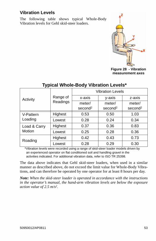
Vibration LevelsThe following table shows typical Whole-BodyVibration levels for Gehl skid-steer loaders.
Typical Whole-Body Vibration Levels*
*Vibration levels were recorded using a range of skid-steer loader models driven by an experienced operator on flat conditioned soil and handling gravel in the activities indicated. For additional vibration data, refer to ISO TR 25398.
The data above indicates that Gehl skid-steer loaders, when used in a similarmanner as described above, do not exceed the limit value for Whole-Body Vibra-tions, and can therefore be operated by one operator for at least 8 hours per day.
Note: When the skid-steer loader is operated in accordance with the instructionsin the operator’s manual, the hand-arm vibration levels are below the exposureaction value of 2.5 m/s2.
ActivityRange of Readings
Vibration Levels
x-axis y-axis z-axis
meter/second2
meter/second2
meter/second2
V-Pattern Loading
Highest 0.53 0.50 1.03
Lowest 0.28 0.24 0.34
Load & Carry Motion
Highest 0.37 0.36 0.83
Lowest 0.25 0.28 0.36
RoadingHighest 0.42 0.43 0.73
Lowest 0.28 0.29 0.30
Figure 28 - Vibration measurement axes
50950012/AP0811 53
Highway Travel
If it becomes necessary to move the loader a long distance, use a properly ratedtrailer. (See Transporting the Loader on page 55.) For short distance highwaytravel, attach an SMV (Slow-Moving Vehicle) emblem (purchased locally) to theback of the loader. For highway operation, install the optional strobe light. Checkstate and local laws and regulations.
Storing the Loader
If the skid-steer loader is to be stored for a long period, in excess of two months,the following procedures are suggested:
1. Fully inflate the tires.
2. Lubricate all grease zerks.
3. Check all fluid levels and replenish as necessary.
4. Add stabilizer to the fuel per the fuel supplier’s recommendations.
5. Remove the battery, charge fully and store in a cool, dry location.
6. Protect against extreme weather conditions such as moisture, sunlight and tem-perature.
Removing Loader from Storage
1. Check the tire air pressure and inflate the tires if they are low.
2. Connect the battery.
3. Check the fan belt tension.
4. Check all fluid levels (engine oil, transmission/hydraulic oil, engine coolantand any attached implements).
5. Start the engine. Observe all gauges. If all gauges are functioning properlyand reading normal, move the machine outside.
6. Once outside, park the machine and let the engine idle for at least five min-utes.
7. Shut the engine off and walk around machine. Make a visual inspection look-ing for evidence of leaks.
54 50950012/AP0811
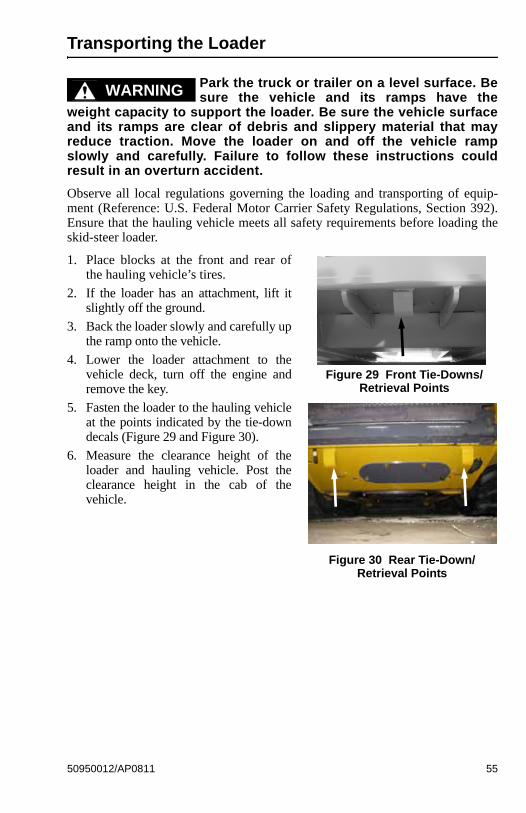
Transporting the Loader
Park the truck or trailer on a level surface. Besure the vehicle and its ramps have the
weight capacity to support the loader. Be sure the vehicle surfaceand its ramps are clear of debris and slippery material that mayreduce traction. Move the loader on and off the vehicle rampslowly and carefully. Failure to follow these instructions couldresult in an overturn accident.
Observe all local regulations governing the loading and transporting of equip-ment (Reference: U.S. Federal Motor Carrier Safety Regulations, Section 392).Ensure that the hauling vehicle meets all safety requirements before loading theskid-steer loader.
1. Place blocks at the front and rear ofthe hauling vehicle’s tires.
2. If the loader has an attachment, lift itslightly off the ground.
3. Back the loader slowly and carefully upthe ramp onto the vehicle.
4. Lower the loader attachment to thevehicle deck, turn off the engine andremove the key.
5. Fasten the loader to the hauling vehicleat the points indicated by the tie-downdecals (Figure 29 and Figure 30).
6. Measure the clearance height of theloader and hauling vehicle. Post theclearance height in the cab of thevehicle.
WARNING
Figure 29 Front Tie-Downs/Retrieval Points
Figure 30 Rear Tie-Down/Retrieval Points
50950012/AP0811 55
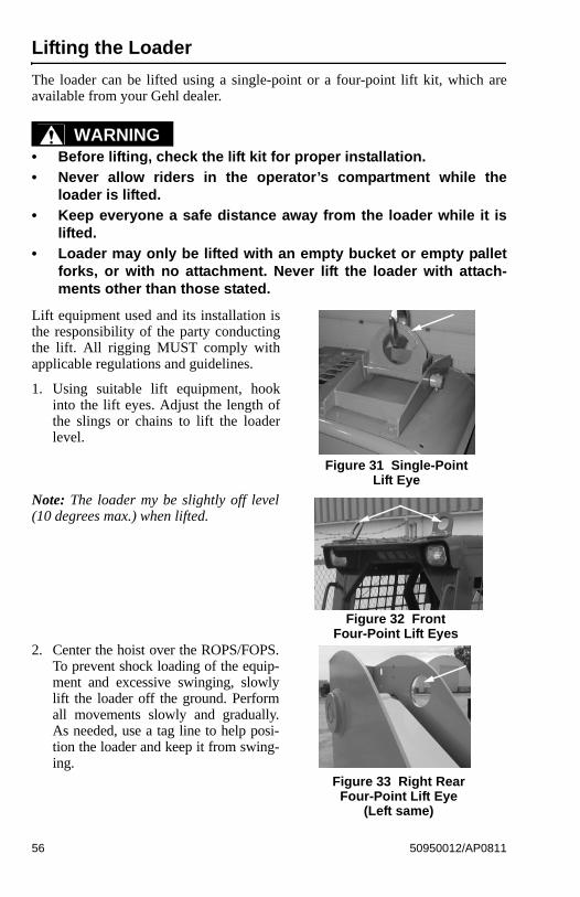
Lifting the Loader
The loader can be lifted using a single-point or a four-point lift kit, which areavailable from your Gehl dealer.
• Before lifting, check the lift kit for proper installation.
• Never allow riders in the operator’s compartment while theloader is lifted.
• Keep everyone a safe distance away from the loader while it islifted.
• Loader may only be lifted with an empty bucket or empty palletforks, or with no attachment. Never lift the loader with attach-ments other than those stated.
Lift equipment used and its installation isthe responsibility of the party conductingthe lift. All rigging MUST comply withapplicable regulations and guidelines.
1. Using suitable lift equipment, hookinto the lift eyes. Adjust the length ofthe slings or chains to lift the loaderlevel.
Note: The loader my be slightly off level(10 degrees max.) when lifted.
2. Center the hoist over the ROPS/FOPS.To prevent shock loading of the equip-ment and excessive swinging, slowlylift the loader off the ground. Performall movements slowly and gradually.As needed, use a tag line to help posi-tion the loader and keep it from swing-ing.
WARNING
Figure 31 Single-Point Lift Eye
Figure 32 FrontFour-Point Lift Eyes
Figure 33 Right Rear Four-Point Lift Eye
(Left same)
56 50950012/AP0811
CHAPTER 5SERVICE
Before servicing the machine, unlessexpressly instructed to the contrary, exercise
the MANDATORY SAFETY SHUTDOWN PROCEDURE (page 6).
After service has been performed, be sure to restore all guards,shields and covers to their original positions before resumingoperation.
This Service chapter details procedures for performing routine maintenancechecks, adjustments and replacements. Most procedures are referred to in theTroubleshooting and Maintenance chapters of this manual. Refer to the Mainte-nance Interval Chart (page 91) for service intervals. Refer to the separate enginemanual for engine-related adjustments, lubrication and service procedures.
Note: All service procedures, except those described under the Dealer Servicestopic are owner-operator responsibilities.
Important: Always dispose of waste lubricating oils and hydraulic fluids accord-ing to local regulations or take to a recycling center for disposal. Do not pouronto the ground or down the drain.
Dealer Services
The following areas of component service, replacement and adjustments requirespecial tools and knowledge for proper servicing and should be performed onlyby your authorized Gehl skid-steer loader dealer: hydrostatic drive components,hydraulic system pumps, valves, hydraulic cylinders, electrical components(other than battery, fuses).
WARNING
50950012/AP0811 57
Replacement Parts
Note: Part numbers may change. Your Gehl dealer will always have the latestpart numbers.
Important: To ensure continued warranty coverage, only genuine Gehl replace-ment filters are to be used.
Part Description Gehl Part No.
Air Cleaner Element, Primary 184146
Air Cleaner Element, Secondary 184195
Hydraulic Oil Filter Element 074830
Engine Oil Filter Element 195568
Main Fuel Filter Cartridge 193024
Small Fuel Filter Cartridge 245005
Fresh Air Intake Filter (heater option) 184708
Recirculation Air Filter (heater option) 184709
58 50950012/AP0811
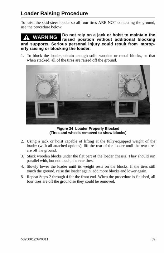
Loader Raising Procedure
To raise the skid-steer loader so all four tires ARE NOT contacting the ground,use the procedure below:
Do not rely on a jack or hoist to maintain theraised position without additional blocking
and supports. Serious personal injury could result from improp-erly raising or blocking the loader.
1. To block the loader, obtain enough solid wooden or metal blocks, so thatwhen stacked, all of the tires are raised off the ground.
2. Using a jack or hoist capable of lifting at the fully-equipped weight of theloader (with all attached options), lift the rear of the loader until the rear tiresare off the ground.
3. Stack wooden blocks under the flat part of the loader chassis. They should runparallel with, but not touch, the rear tires.
4. Slowly lower the loader until its weight rests on the blocks. If the tires stilltouch the ground, raise the loader again, add more blocks and lower again.
5. Repeat Steps 2 through 4 for the front end. When the procedure is finished, allfour tires are off the ground so they could be removed.
WARNING
Figure 34 Loader Properly Blocked(Tires and wheels removed to show blocks)
50950012/AP0811 59
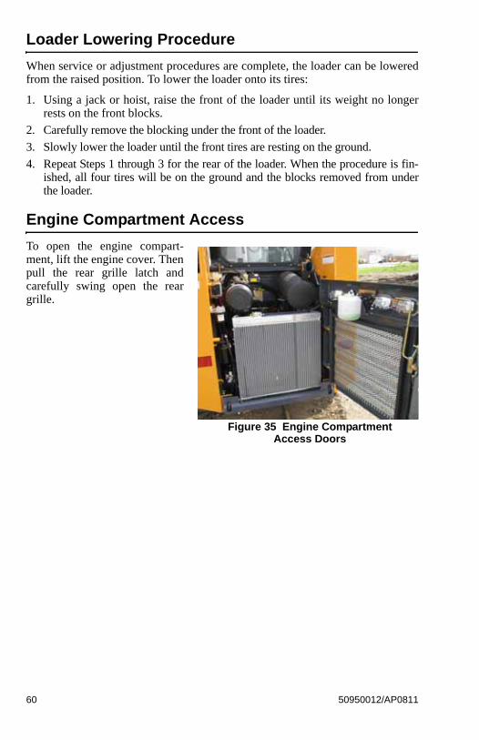
Loader Lowering Procedure
When service or adjustment procedures are complete, the loader can be loweredfrom the raised position. To lower the loader onto its tires:
1. Using a jack or hoist, raise the front of the loader until its weight no longerrests on the front blocks.
2. Carefully remove the blocking under the front of the loader.
3. Slowly lower the loader until the front tires are resting on the ground.
4. Repeat Steps 1 through 3 for the rear of the loader. When the procedure is fin-ished, all four tires will be on the ground and the blocks removed from underthe loader.
Engine Compartment Access
To open the engine compart-ment, lift the engine cover. Thenpull the rear grille latch andcarefully swing open the reargrille.
Figure 35 Engine CompartmentAccess Doors
60 50950012/AP0811
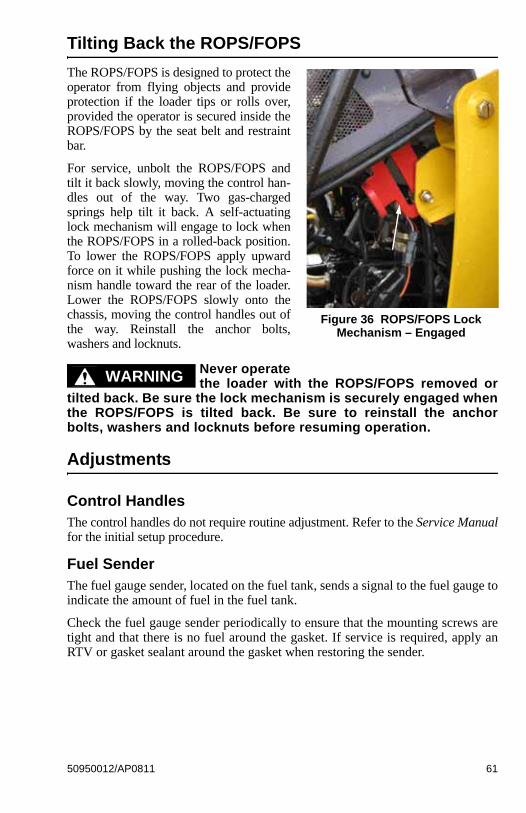
Tilting Back the ROPS/FOPS
The ROPS/FOPS is designed to protect theoperator from flying objects and provideprotection if the loader tips or rolls over,provided the operator is secured inside theROPS/FOPS by the seat belt and restraintbar.
For service, unbolt the ROPS/FOPS andtilt it back slowly, moving the control han-dles out of the way. Two gas-chargedsprings help tilt it back. A self-actuatinglock mechanism will engage to lock whenthe ROPS/FOPS in a rolled-back position.To lower the ROPS/FOPS apply upwardforce on it while pushing the lock mecha-nism handle toward the rear of the loader.Lower the ROPS/FOPS slowly onto thechassis, moving the control handles out ofthe way. Reinstall the anchor bolts,washers and locknuts.
Never operatethe loader with the ROPS/FOPS removed or
tilted back. Be sure the lock mechanism is securely engaged whenthe ROPS/FOPS is tilted back. Be sure to reinstall the anchorbolts, washers and locknuts before resuming operation.
Adjustments
Control HandlesThe control handles do not require routine adjustment. Refer to the Service Manualfor the initial setup procedure.
Fuel SenderThe fuel gauge sender, located on the fuel tank, sends a signal to the fuel gauge toindicate the amount of fuel in the fuel tank.
Check the fuel gauge sender periodically to ensure that the mounting screws aretight and that there is no fuel around the gasket. If service is required, apply anRTV or gasket sealant around the gasket when restoring the sender.
Figure 36 ROPS/FOPS Lock Mechanism – Engaged
WARNING
50950012/AP0811 61
Foreign Material Removal
The loader should be cleared daily of dirt and other foreign materials in the fol-lowing areas:
• around the lift cylinders• at the front of the loader• on the hitch, especially around tilt cylinder• around the hydraulic oil reservoir breather• in the engine compartment• in the operator’s compartment• engine side screen covers (attached at back of the ROPS/FOPS)
Important: Build up of foreign materials in these areas can interfere with theoperation of the loader, cause component damage or become a fire hazard.
Lubrication
Listed on page 63 are the temperature ranges and types of lubricants for thismachine. Refer to the separate engine manual for more information regardingengine lubricants, quantities and grades required.
Note: Refer to the specific service sections for detailed information on periodicchecking and replenishing of lubricants.
Refer to Figure 37 for grease fitting locations. Wipe dirt from the fittings beforegreasing them to prevent contamination. Replace any missing or damaged fit-tings. To minimize dirt build-up, avoid excessive greasing.
Important: Always dispose of waste lubricating oils and hydraulic fluids accord-ing to local regulations or take to a recycling center for disposal. Do not pouronto the ground or down the drain.
62 50950012/AP0811
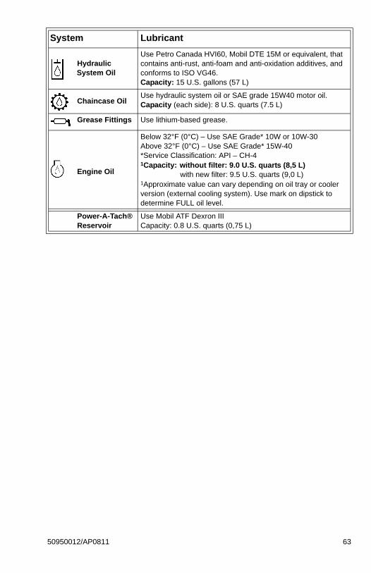
System Lubricant
Hydraulic System Oil
Use Petro Canada HVI60, Mobil DTE 15M or equivalent, that contains anti-rust, anti-foam and anti-oxidation additives, and conforms to ISO VG46.Capacity: 15 U.S. gallons (57 L)
Chaincase OilUse hydraulic system oil or SAE grade 15W40 motor oil.Capacity (each side): 8 U.S. quarts (7.5 L)
Grease Fittings Use lithium-based grease.
Engine Oil
Below 32°F (0°C) – Use SAE Grade* 10W or 10W-30Above 32°F (0°C) – Use SAE Grade* 15W-40*Service Classification: API – CH-41Capacity: without filter: 9.0 U.S. quarts (8,5 L) with new filter: 9.5 U.S. quarts (9,0 L)1Approximate value can vary depending on oil tray or cooler version (external cooling system). Use mark on dipstick to determine FULL oil level.
Power-A-Tach®Reservoir
Use Mobil ATF Dexron IIICapacity: 0.8 U.S. quarts (0,75 L)
50950012/AP0811 63
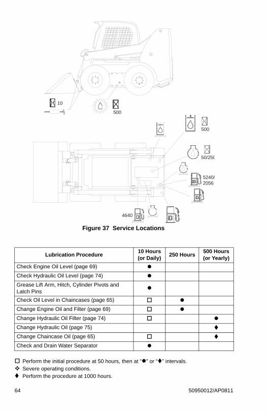
Lubrication Procedure10 Hours (or Daily)
250 Hours500 Hours (or Yearly)
Check Engine Oil Level (page 69)
Check Hydraulic Oil Level (page 74)
Grease Lift Arm, Hitch, Cylinder Pivots and Latch Pins
Check Oil Level in Chaincases (page 65)
Change Engine Oil and Filter (page 69)
Change Hydraulic Oil Filter (page 74)
Change Hydraulic Oil (page 75)
Change Chaincase Oil (page 65)
Check and Drain Water Separator
Perform the initial procedure at 50 hours, then at “” or “” intervals. Severe operating conditions. Perform the procedure at 1000 hours.
Figure 37 Service Locations
50/250
500
10
500
5240/2056
4640
64 50950012/AP0811
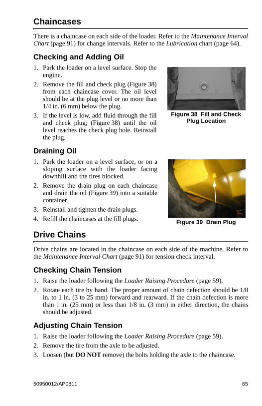
Chaincases
There is a chaincase on each side of the loader. Refer to the Maintenance IntervalChart (page 91) for change intervals. Refer to the Lubrication chart (page 64).
Checking and Adding Oil1. Park the loader on a level surface. Stop the
engine.
2. Remove the fill and check plug (Figure 38)from each chaincase cover. The oil levelshould be at the plug level or no more than1/4 in. (6 mm) below the plug.
3. If the level is low, add fluid through the filland check plug; (Figure 38) until the oillevel reaches the check plug hole. Reinstallthe plug.
Draining Oil1. Park the loader on a level surface, or on a
sloping surface with the loader facingdownhill and the tires blocked.
2. Remove the drain plug on each chaincaseand drain the oil (Figure 39) into a suitablecontainer.
3. Reinstall and tighten the drain plugs.
4. Refill the chaincases at the fill plugs.
Drive Chains
Drive chains are located in the chaincase on each side of the machine. Refer tothe Maintenance Interval Chart (page 91) for tension check interval.
Checking Chain Tension1. Raise the loader following the Loader Raising Procedure (page 59).
2. Rotate each tire by hand. The proper amount of chain defection should be 1/8in. to 1 in. (3 to 25 mm) forward and rearward. If the chain defection is morethan 1 in. (25 mm) or less than 1/8 in. (3 mm) in either direction, the chainsshould be adjusted.
Adjusting Chain Tension1. Raise the loader following the Loader Raising Procedure (page 59).
2. Remove the tire from the axle to be adjusted.
3. Loosen (but DO NOT remove) the bolts holding the axle to the chaincase.
Figure 38 Fill and Check Plug Location
Figure 39 Drain Plug
50950012/AP0811 65

4. Front Chain Tension – To tighten the front chain, move the front axle assem-bly toward the front of the loader. To loosen the chain, move the front axleassembly toward the rear of the loader.
Rear Chain Tension – To tighten the rear chain, move the rear axle assemblyrearward. To loosen the chain, move the rear axle assembly toward the frontof the loader.
5. After proper tension is achieved, retighten the bolts.
Important: Be careful not to over-tighten the drive chains. Over-tightening willcause premature drive chain and axle sprocket wear.
6. Reinstall the tire.
7. Repeat Steps 2 through 6 for any other axle requiring adjustment.
8. Lower the loader following the Loader Lowering Procedure (page 60).
66 50950012/AP0811
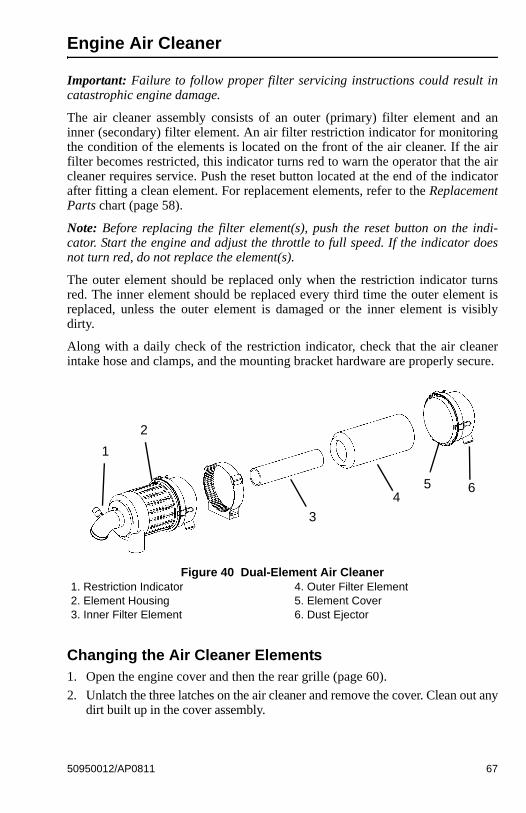
Engine Air Cleaner
Important: Failure to follow proper filter servicing instructions could result incatastrophic engine damage.
The air cleaner assembly consists of an outer (primary) filter element and aninner (secondary) filter element. An air filter restriction indicator for monitoringthe condition of the elements is located on the front of the air cleaner. If the airfilter becomes restricted, this indicator turns red to warn the operator that the aircleaner requires service. Push the reset button located at the end of the indicatorafter fitting a clean element. For replacement elements, refer to the ReplacementParts chart (page 58).
Note: Before replacing the filter element(s), push the reset button on the indi-cator. Start the engine and adjust the throttle to full speed. If the indicator doesnot turn red, do not replace the element(s).
The outer element should be replaced only when the restriction indicator turnsred. The inner element should be replaced every third time the outer element isreplaced, unless the outer element is damaged or the inner element is visiblydirty.
Along with a daily check of the restriction indicator, check that the air cleanerintake hose and clamps, and the mounting bracket hardware are properly secure.
Changing the Air Cleaner Elements1. Open the engine cover and then the rear grille (page 60).
2. Unlatch the three latches on the air cleaner and remove the cover. Clean out anydirt built up in the cover assembly.
Figure 40 Dual-Element Air Cleaner1. Restriction Indicator2. Element Housing3. Inner Filter Element
4. Outer Filter Element5. Element Cover6. Dust Ejector
1
2
3
45 6
50950012/AP0811 67
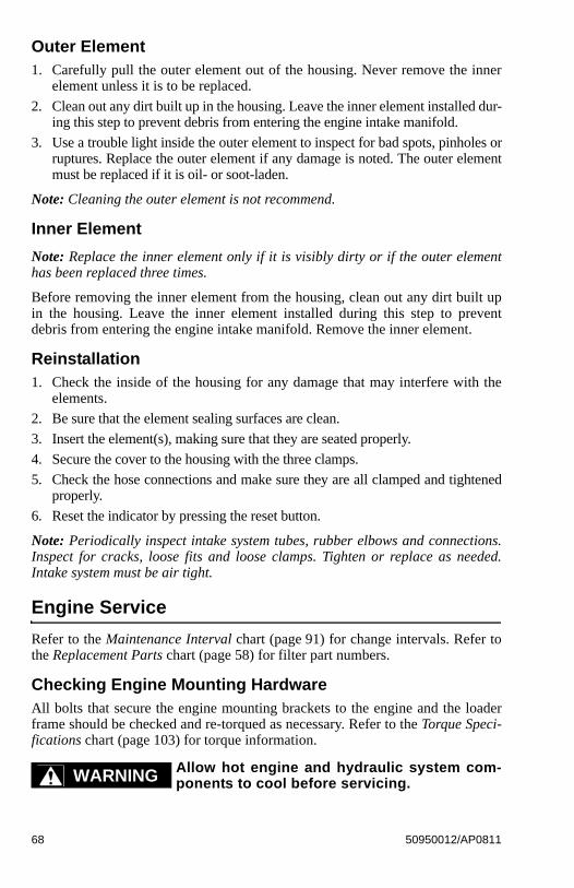
Outer Element1. Carefully pull the outer element out of the housing. Never remove the inner
element unless it is to be replaced.
2. Clean out any dirt built up in the housing. Leave the inner element installed dur-ing this step to prevent debris from entering the engine intake manifold.
3. Use a trouble light inside the outer element to inspect for bad spots, pinholes orruptures. Replace the outer element if any damage is noted. The outer elementmust be replaced if it is oil- or soot-laden.
Note: Cleaning the outer element is not recommend.
Inner Element
Note: Replace the inner element only if it is visibly dirty or if the outer elementhas been replaced three times.
Before removing the inner element from the housing, clean out any dirt built upin the housing. Leave the inner element installed during this step to preventdebris from entering the engine intake manifold. Remove the inner element.
Reinstallation1. Check the inside of the housing for any damage that may interfere with the
elements.
2. Be sure that the element sealing surfaces are clean.
3. Insert the element(s), making sure that they are seated properly.
4. Secure the cover to the housing with the three clamps.
5. Check the hose connections and make sure they are all clamped and tightenedproperly.
6. Reset the indicator by pressing the reset button.
Note: Periodically inspect intake system tubes, rubber elbows and connections.Inspect for cracks, loose fits and loose clamps. Tighten or replace as needed.Intake system must be air tight.
Engine Service
Refer to the Maintenance Interval chart (page 91) for change intervals. Refer tothe Replacement Parts chart (page 58) for filter part numbers.
Checking Engine Mounting HardwareAll bolts that secure the engine mounting brackets to the engine and the loaderframe should be checked and re-torqued as necessary. Refer to the Torque Speci-fications chart (page 103) for torque information.
Allow hot engine and hydraulic system com-ponents to cool before servicing.WARNING
68 50950012/AP0811
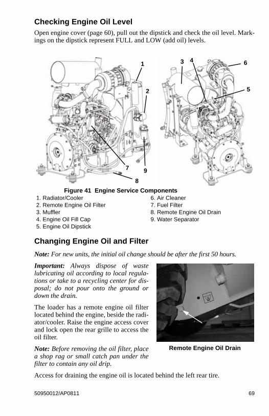
Checking Engine Oil LevelOpen engine cover (page 60), pull out the dipstick and check the oil level. Mark-ings on the dipstick represent FULL and LOW (add oil) levels.
Changing Engine Oil and Filter
Note: For new units, the initial oil change should be after the first 50 hours.
Important: Always dispose of wastelubricating oil according to local regula-tions or take to a recycling center for dis-posal; do not pour onto the ground ordown the drain.
The loader has a remote engine oil filterlocated behind the engine, beside the radi-ator/cooler. Raise the engine access coverand lock open the rear grille to access theoil filter.
Note: Before removing the oil filter, placea shop rag or small catch pan under thefilter to contain any oil drip.
Access for draining the engine oil is located behind the left rear tire.
Figure 41 Engine Service Components1. Radiator/Cooler2. Remote Engine Oil Filter3. Muffler4. Engine Oil Fill Cap5. Engine Oil Dipstick
6. Air Cleaner7. Fuel Filter8. Remote Engine Oil Drain9. Water Separator
1
2
3 4
5
6
7
8
5
9
Remote Engine Oil Drain
50950012/AP0811 69
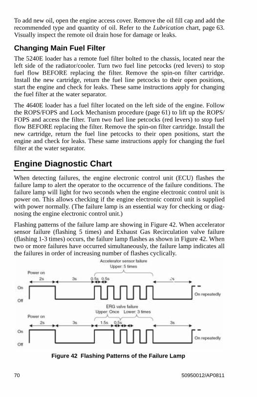
To add new oil, open the engine access cover. Remove the oil fill cap and add therecommended type and quantity of oil. Refer to the Lubrication chart, page 63.Visually inspect the remote oil drain hose for damage or leaks.
Changing Main Fuel FilterThe 5240E loader has a remote fuel filter bolted to the chassis, located near theleft side of the radiator/cooler. Turn two fuel line petcocks (red levers) to stopfuel flow BEFORE replacing the filter. Remove the spin-on filter cartridge.Install the new cartridge, return the fuel line petcocks to their open positions,start the engine and check for leaks. These same instructions apply for changingthe fuel filter at the water separator.
The 4640E loader has a fuel filter located on the left side of the engine. Followthe ROPS/FOPS and Lock Mechanism procedure (page 61) to lift up the ROPS/FOPS and access the filter. Turn two fuel line petcocks (red levers) to stop fuelflow BEFORE replacing the filter. Remove the spin-on filter cartridge. Install thenew cartridge, return the fuel line petcocks to their open positions, start theengine and check for leaks. These same instructions apply for changing the fuelfilter at the water separator.
Engine Diagnostic Chart
When detecting failures, the engine electronic control unit (ECU) flashes thefailure lamp to alert the operator to the occurrence of the failure conditions. Thefailure lamp will light for two seconds when the engine electronic control unit ispower on. This allows checking if the engine electronic control unit is suppliedwith power normally. (The failure lamp is an essential way for checking or diag-nosing the engine electronic control unit.)
Flashing patterns of the failure lamp are showing in Figure 42. When acceleratorsensor failure (flashing 5 times) and Exhaust Gas Recirculation valve failure(flashing 1-3 times) occurs, the failure lamp flashes as shown in Figure 42. Whentwo or more failures have occurred simultaneously, the failure lamp indicates allthe failures in order of increasing number of flashes cyclically.
Figure 42 Flashing Patterns of the Failure Lamp
70 50950012/AP0811
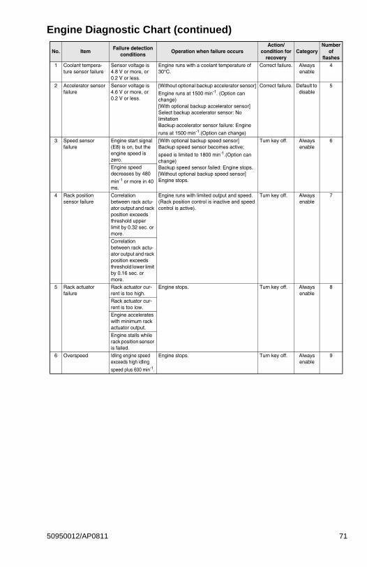
Engine Diagnostic Chart (continued)
No. ItemFailure detection
conditionsOperation when failure occurs
Action/condition for
recoveryCategory
Number of
flashes1 Coolant tempera-
ture sensor failureSensor voltage is 4.8 V or more, or 0.2 V or less.
Engine runs with a coolant temperature of 30°C.
Correct failure. Always enable
4
2 Accelerator sensor failure
Sensor voltage is 4.6 V or more, or 0.2 V or less.
[Without optional backup accelerator sensor]
Engine runs at 1500 min-1. (Option can change)[With optional backup accelerator sensor]Select backup accelerator sensor: No limitationBackup accelerator sensor failure: Engine
runs at 1500 min-1.(Option can change)
Correct failure. Default to disable
5
3 Speed sensor failure
Engine start signal (E8) is on, but the engine speed is zero.
[With optional backup speed sensor]Backup speed sensor becomes active;
speed is limited to 1800 min-1.(Option can change)Backup speed sensor failed: Engine stops.[Without optional backup speed sensor]Engine stops.
Turn key off. Always enable
6
Engine speed decreases by 480
min-1 or more in 40 ms.
4 Rack position sensor failure
Correlation between rack actu-ator output and rack position exceeds threshold upper limit by 0.32 sec. or more.
Engine runs with limited output and speed. (Rack position control is inactive and speed control is active).
Turn key off. Always enable
7
Correlation between rack actu-ator output and rack position exceeds threshold lower limit by 0.16 sec. or more.
5 Rack actuator failure
Rack actuator cur-rent is too high.
Engine stops. Turn key off. Always enable
8
Rack actuator cur-rent is too low.Engine accelerates with minimum rack actuator output.
Engine stalls while rack position sensor is failed.
6 Overspeed Idling engine speed exceeds high idling
speed plus 600 min-1.
Engine stops. Turn key off. Always enable
9
50950012/AP0811 71
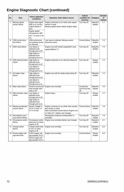
Engine Diagnostic Chart (continued)
7 Backup speed sensor failure
Engine start signal (E8) is on, but the engine speed is zero.
Engine continues to run while main speed sensor is used. Backup speed sensor failed: Engine stops.
Turn key off. Default to disable
1-1
Engine speed decreases by 480
min-1 or more in 40 ms.
8 CAN communica-tion failure
CAN communica-tion packets cannot be received.
Last value is retained. Backup sensor becomes active.
Correct failure. Default to enable
1-2
9 EGR valve failure Low status is detected even through port is off.
Engine runs with limited output(92%) and
speed(1800min-1).
Turn key off. Default to disable
1-3
High status is detected even through port is on.
10 CSD solenoid valve failure
High status is detected even through port is off.
Engine continues to run with port being off. Turn key off. Always enable
1-4
Low status is detected even through port is on.
11 Air heater relay failure
High status is detected even through port is off.
Engine runs with air heater relay being off. Turn key off. Default to enable
1-5
Low status is detected even through port is on.
12 Main relay failure Power is not shut off even though main relay is off.
Engine runs normally. Correct fail-ure.Or turn key off.
Default to disable
1-6
13 Rack actuator relay failure
Low status is detected even through port is off.
Engine stops. Turn key off. Always enable
1-7
High status is detected even through port is on.
14 Backup accelerator sensor failure
Sensor voltage is 4.6 V or more, or 0.2 V or less.
Engine continues to run while main acceler-ator sensor is used. Main accelerator sensor failure: Engine runs
at 1500 min-1.(Option can change)
Correct failure. Default to enable
1-8
15 Atmospheric pres-sure sensor failure
Atmospheric pressure compensation is canceled.
Turn key off. Default to enable
1-9
16 Oil pressure switch failure
Oil pressure switch fails to turn on when engine is off.
Engine runs normally.(Option can change) Turn key off. Default to enable
2-1
17 Charge switch failure
Charge switch fails to turn on when engine is off.
Engine runs normally. Turn key off. Default to enable
2-2
18 Power supply volt-age abnormal
E-ECU supply volt-age exceeds 10.0 V.
Engine runs normally. Correct failure. Always enable
2-3
E-ECU supply volt-age exceeds 16.0 V.
No. ItemFailure detection
conditionsOperation when failure occurs
Action/condition for
recoveryCategory
Number of
flashes
72 50950012/AP0811
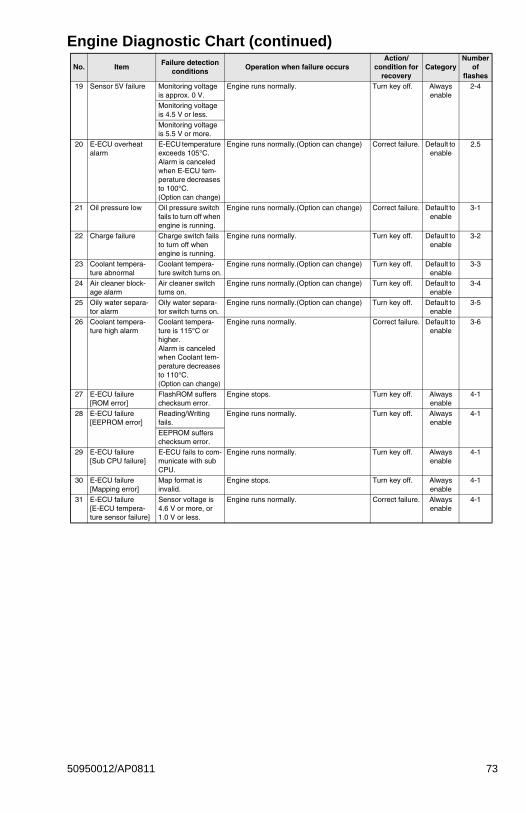
Engine Diagnostic Chart (continued)
19 Sensor 5V failure Monitoring voltage is approx. 0 V.
Engine runs normally. Turn key off. Always enable
2-4
Monitoring voltage is 4.5 V or less.
Monitoring voltage is 5.5 V or more.
20 E-ECU overheat alarm
E-ECU temperature exceeds 105°C.Alarm is canceled when E-ECU tem-perature decreases to 100°C. (Option can change)
Engine runs normally.(Option can change) Correct failure. Default to enable
2.5
21 Oil pressure low Oil pressure switch fails to turn off when engine is running.
Engine runs normally.(Option can change) Correct failure. Default to enable
3-1
22 Charge failure Charge switch fails to turn off when engine is running.
Engine runs normally. Turn key off. Default to enable
3-2
23 Coolant tempera-ture abnormal
Coolant tempera-ture switch turns on.
Engine runs normally.(Option can change) Turn key off. Default to enable
3-3
24 Air cleaner block-age alarm
Air cleaner switch turns on.
Engine runs normally.(Option can change) Turn key off. Default to enable
3-4
25 Oily water separa-tor alarm
Oily water separa-tor switch turns on.
Engine runs normally.(Option can change) Turn key off. Default to enable
3-5
26 Coolant tempera-ture high alarm
Coolant tempera-ture is 115°C or higher.Alarm is canceled when Coolant tem-perature decreases to 110°C. (Option can change)
Engine runs normally. Correct failure. Default to enable
3-6
27 E-ECU failure[ROM error]
FlashROM suffers checksum error.
Engine stops. Turn key off. Always enable
4-1
28 E-ECU failure[EEPROM error]
Reading/Writing fails.
Engine runs normally. Turn key off. Always enable
4-1
EEPROM suffers checksum error.
29 E-ECU failure[Sub CPU failure]
E-ECU fails to com-municate with sub CPU.
Engine runs normally. Turn key off. Always enable
4-1
30 E-ECU failure[Mapping error]
Map format is invalid.
Engine stops. Turn key off. Always enable
4-1
31 E-ECU failure[E-ECU tempera-ture sensor failure]
Sensor voltage is 4.6 V or more, or 1.0 V or less.
Engine runs normally. Correct failure. Always enable
4-1
No. ItemFailure detection
conditionsOperation when failure occurs
Action/condition for
recoveryCategory
Number of
flashes
50950012/AP0811 73
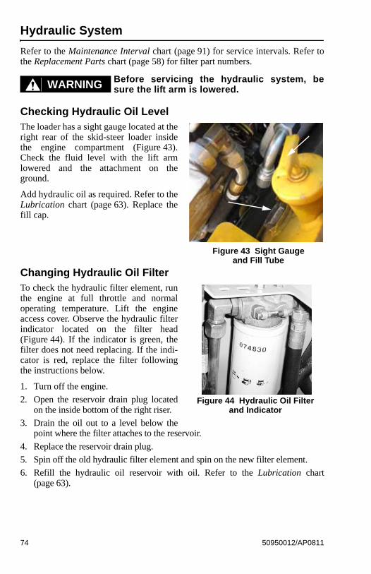
Hydraulic System
Refer to the Maintenance Interval chart (page 91) for service intervals. Refer tothe Replacement Parts chart (page 58) for filter part numbers.
Before servicing the hydraulic system, besure the lift arm is lowered.
Checking Hydraulic Oil LevelThe loader has a sight gauge located at theright rear of the skid-steer loader insidethe engine compartment (Figure 43).Check the fluid level with the lift armlowered and the attachment on theground.
Add hydraulic oil as required. Refer to theLubrication chart (page 63). Replace thefill cap.
Changing Hydraulic Oil FilterTo check the hydraulic filter element, runthe engine at full throttle and normaloperating temperature. Lift the engineaccess cover. Observe the hydraulic filterindicator located on the filter head(Figure 44). If the indicator is green, thefilter does not need replacing. If the indi-cator is red, replace the filter followingthe instructions below.
1. Turn off the engine.
2. Open the reservoir drain plug locatedon the inside bottom of the right riser.
3. Drain the oil out to a level below thepoint where the filter attaches to the reservoir.
4. Replace the reservoir drain plug.
5. Spin off the old hydraulic filter element and spin on the new filter element.
6. Refill the hydraulic oil reservoir with oil. Refer to the Lubrication chart(page 63).
WARNING
Figure 43 Sight Gauge and Fill Tube
Figure 44 Hydraulic Oil Filter and Indicator
74 50950012/AP0811
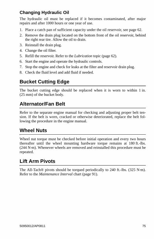
Changing Hydraulic OilThe hydraulic oil must be replaced if it becomes contaminated, after majorrepairs and after 1000 hours or one year of use.
1. Place a catch pan of sufficient capacity under the oil reservoir, see page 62.
2. Remove the drain plug located on the bottom front of the oil reservoir, behindthe right rear tire. Allow the oil to drain.
3. Reinstall the drain plug.
4. Change the oil filter.
5. Refill the reservoir. Refer to the Lubrication topic (page 62).
6. Start the engine and operate the hydraulic controls.
7. Stop the engine and check for leaks at the filter and reservoir drain plug.
8. Check the fluid level and add fluid if needed.
Bucket Cutting Edge
The bucket cutting edge should be replaced when it is worn to within 1 in.(25 mm) of the bucket body.
Alternator/Fan Belt
Refer to the separate engine manual for checking and adjusting proper belt ten-sion. If the belt is worn, cracked or otherwise deteriorated, replace the belt fol-lowing the procedure in the engine manual.
Wheel Nuts
Wheel nut torque must be checked before initial operation and every two hoursthereafter until the wheel mounting hardware torque remains at 180 ft.-lbs.(244 N·m). Whenever wheels are removed and reinstalled this procedure must berepeated.
Lift Arm Pivots
The All-Tach® pivots should be torqued periodically to 240 ft.-lbs. (325 N·m).Refer to the Maintenance Interval chart (page 91).
50950012/AP0811 75
Cooling System
Important: Check the cooling system daily to prevent overheating, loss of perfor-mance and engine damage.
Cleaning the Cooling System
Allow sufficient time for the radiator to coolbefore working on or near it. Parts get
extremely hot during operation and can burn you.
The oil cooler assembly is mounted between the engine and the hinged rear grille.When operating correctly, air is blown through the openings between the fins by theengine fan. During operation dust and debris can build up on the engine side of theoil cooler and restrict air flow through the fins. To remove this restriction, use com-pressed air or a water hose and direct the flow through the fins from the rear of thecooler towards the engine.
Tires
Inflating or servicing tires can be dangerous.When possible, trained personnel should ser-
vice and mount tires. To avoid possible death or serious injury,follow the safety precautions below.
To keep tire wear even, rotate the tires from front to rear and rear to front.
It is important to keep the same size tire on each side of the loader to preventexcessive wear on tires, chains, or other damage. If different sizes are used, tireswill be turning at different speeds, causing excessive wear.
Note: The tread bar of all tires should face the same direction.
BE SURE the rim is clean and free of rust.
Lubricate the tire beads and rim flanges with a soap solution. Do NOT use oilor grease.
Use a clip-on tire chuck with remote hose and gauge, allowing you to standclear while inflating the tire.
NEVER inflate beyond 35 psi (240 kPa) to seat the beads. If the beads havenot seated by the time the pressure reaches 35 psi (240 kPa), deflate the as-sembly, reposition the tire on the rim, lubricate both parts and re-inflate. In-flation pressure beyond 35 psi (240 kPa) with unseated beads may break thebead or rim with explosive force sufficient to cause death or serious injury.
After seating the beads, adjust the inflation pressure to the recommendedoperating pressure.
Do NOT weld, braze or otherwise attempt to repair and use a damaged rim.
WARNING
WARNING
76 50950012/AP0811
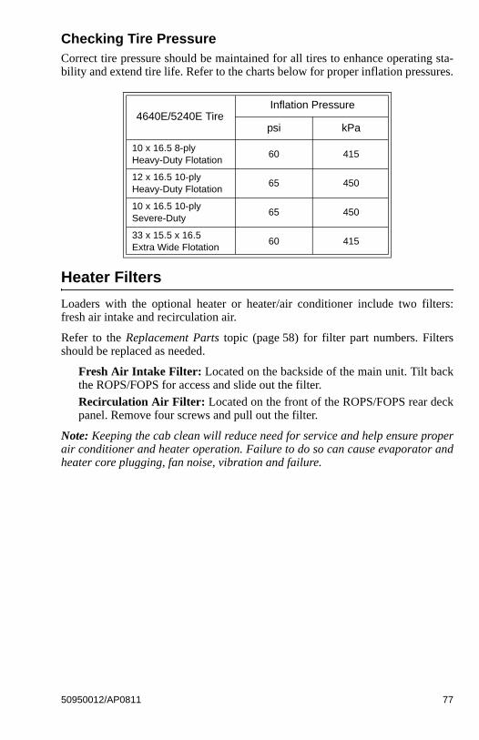
Checking Tire PressureCorrect tire pressure should be maintained for all tires to enhance operating sta-bility and extend tire life. Refer to the charts below for proper inflation pressures.
Heater Filters
Loaders with the optional heater or heater/air conditioner include two filters:fresh air intake and recirculation air.
Refer to the Replacement Parts topic (page 58) for filter part numbers. Filtersshould be replaced as needed.
Fresh Air Intake Filter: Located on the backside of the main unit. Tilt backthe ROPS/FOPS for access and slide out the filter.
Recirculation Air Filter: Located on the front of the ROPS/FOPS rear deckpanel. Remove four screws and pull out the filter.
Note: Keeping the cab clean will reduce need for service and help ensure properair conditioner and heater operation. Failure to do so can cause evaporator andheater core plugging, fan noise, vibration and failure.
4640E/5240E TireInflation Pressure
psi kPa
10 x 16.5 8-ply Heavy-Duty Flotation
60 415
12 x 16.5 10-ply Heavy-Duty Flotation
65 450
10 x 16.5 10-ply Severe-Duty
65 450
33 x 15.5 x 16.5 Extra Wide Flotation
60 415
50950012/AP0811 77
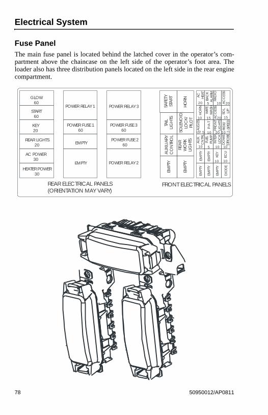
Electrical System
Fuse PanelThe main fuse panel is located behind the latched cover in the operator’s com-partment above the chaincase on the left side of the operator’s foot area. Theloader also has three distribution panels located on the left side in the rear enginecompartment.
FRONT ELECTRICAL PANELSREAR ELECTRICAL PANELS(ORIENTATION MAY VARY)
GLOW60
START60
KEY20
REAR LIGHTS20
AC POWER30
HEATER POWER30
POWER RELAY 1
POWER FUSE 160
EMPTY
EMPTY
POWER RELAY 3
POWER FUSE 360
POWER FUSE 260
POWER RELAY 2EM
PTY
EMPT
Y
AUX
ILIA
RYC
ON
TRO
L
REA
RW
ORK
LIG
HTS
TAIL
LIG
HTS
SAFE
TYST
ART
HO
RNSO
LEN
OID
LOC
K/PI
LOT
EMPT
Y
EMPT
Y
EMPT
Y
EMPT
Y
EMPT
Y
DIO
DE
KEY
ECU
AU
X.
CN
TRL
FUEL
PUM
PIN
TER
LOC
KD
OM
EST
RO
BE
GA
UGES
P-A
-T
FRO
NT
LIG
HTS
RID
E/2
-SPE
ED
HO
RN
WIP
EW
ASH
AC
CES
S
SOL.
L/P
AC
HEA
TBA
CK
ALA
RMRA
DIO
AC
CES
S
20 20
20
20
5
5
10
10
10 10
101010
10 10
15 15
7.5
78 50950012/AP0811
Battery
Before servicing the battery or electricalsystem, be sure the battery disconnect switch
(optional) is in the OFF position. If not equipped with an electricaldisconnect switch, remove the negative ( - ) battery cable from thebattery post.
The battery on the loader is a 12-volt, wet-cell battery. To access the battery on a4640E loader, open the engine access cover, unlatch and open the rear grille. Toaccess the battery on a 5240E loader, follow the ROPS/FOPS and Lock Mecha-nism procedure (page 61) to lift up the ROPS/FOPS and access the battery.
The 4640E and 5240E loaders have remote battery terminals as standard equip-ment installed.
The battery top must be kept clean. Clean it with an alkaline solution (ammoniaor baking soda and water). After foaming has stopped, flush the battery top withclean water. If the terminals and cable connection clamps are corroded or have abuild-up, disconnect the cables and clean the terminals and clamps with the samealkaline solution.
Explosive gas is produced when a battery isin use or being charged. Keep flames or
sparks away from the battery area. ALWAYS charge the battery ina well-ventilated area.
Never lay a metal object on top of a battery, because a short circuitcan result.
Battery acid is harmful on contact with skin or fabrics. If acid spills,follow these first-aid tips:
1. Immediately remove any clothing on which acid spills.
2. If acid contacts the skin, rinse the affected area with running waterfor 10 to 15 minutes.
3. If acid contacts the eyes, flood the eyes with running water for 10to 15 minutes. See a doctor at once. Never use any medication oreye drops unless prescribed by the doctor.
4. To neutralize acid spilled on the floor, use one of the following mix-tures:
a. 1 pound (0.5 kg) of baking soda in 1 gallon (4 L) of water, or
b. 1 pint (0.5 L) of household ammonia in 1 gallon (4 L) of waterWhenever the battery is removed, be sure to disconnect the nega-tive (-) battery terminal connection first
WARNING
WARNING
50950012/AP0811 79

80 50950012/AP0811
Notes
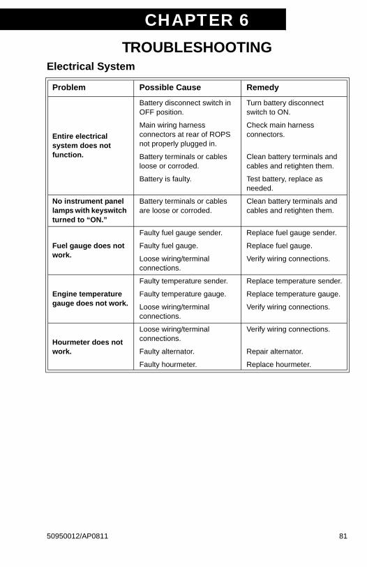
CHAPTER 6TROUBLESHOOTING
Electrical System
Problem Possible Cause Remedy
Entire electrical system does not function.
Battery disconnect switch in OFF position.
Turn battery disconnect switch to ON.
Main wiring harness connectors at rear of ROPS not properly plugged in.
Check main harness connectors.
Battery terminals or cables loose or corroded.
Clean battery terminals and cables and retighten them.
Battery is faulty. Test battery, replace as needed.
No instrument panel lamps with keyswitch turned to “ON.”
Battery terminals or cables are loose or corroded.
Clean battery terminals and cables and retighten them.
Fuel gauge does not work.
Faulty fuel gauge sender. Replace fuel gauge sender.
Faulty fuel gauge. Replace fuel gauge.
Loose wiring/terminal connections.
Verify wiring connections.
Engine temperature gauge does not work.
Faulty temperature sender. Replace temperature sender.
Faulty temperature gauge. Replace temperature gauge.
Loose wiring/terminal connections.
Verify wiring connections.
Hourmeter does not work.
Loose wiring/terminal connections.
Verify wiring connections.
Faulty alternator. Repair alternator.
Faulty hourmeter. Replace hourmeter.
50950012/AP0811 81
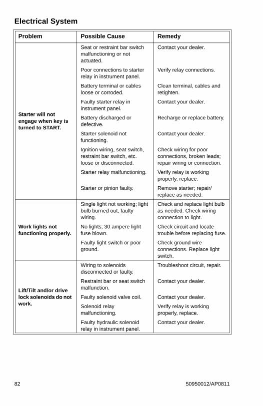
Starter will not engage when key is turned to START.
Seat or restraint bar switch malfunctioning or not actuated.
Contact your dealer.
Poor connections to starter relay in instrument panel.
Verify relay connections.
Battery terminal or cables loose or corroded.
Clean terminal, cables and retighten.
Faulty starter relay in instrument panel.
Contact your dealer.
Battery discharged or defective.
Recharge or replace battery.
Starter solenoid not functioning.
Contact your dealer.
Ignition wiring, seat switch, restraint bar switch, etc. loose or disconnected.
Check wiring for poor connections, broken leads; repair wiring or connection.
Starter relay malfunctioning. Verify relay is working properly, replace.
Starter or pinion faulty. Remove starter; repair/replace as needed.
Work lights not functioning properly.
Single light not working; light bulb burned out, faulty wiring.
Check and replace light bulb as needed. Check wiring connection to light.
No lights; 30 ampere light fuse blown.
Check circuit and locate trouble before replacing fuse.
Faulty light switch or poor ground.
Check ground wire connections. Replace light switch.
Lift/Tilt and/or drive lock solenoids do not work.
Wiring to solenoids disconnected or faulty.
Troubleshoot circuit, repair.
Restraint bar or seat switch malfunction.
Contact your dealer.
Faulty solenoid valve coil. Contact your dealer.
Solenoid relay malfunctioning.
Verify relay is working properly, replace.
Faulty hydraulic solenoid relay in instrument panel.
Contact your dealer.
Electrical System
Problem Possible Cause Remedy
82 50950012/AP0811
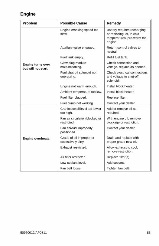
Engine
Problem Possible Cause Remedy
Engine turns over but will not start.
Engine cranking speed too slow.
Battery requires recharging or replacing, or, in cold temperatures, pre-warm the engine.
Auxiliary valve engaged. Return control valves to neutral.
Fuel tank empty. Refill fuel tank.
Glow plug module malfunctioning.
Check connection and voltage, replace as needed.
Fuel shut-off solenoid not energizing.
Check electrical connections and voltage to shut-off solenoid.
Engine not warm enough. Install block heater.
Ambient temperature too low. Install block heater.
Fuel filter plugged. Replace filter.
Fuel pump not working. Contact your dealer.
Engine overheats.
Crankcase oil level too low or too high.
Add or remove oil as required.
Fan air circulation blocked or restricted.
With engine off, remove blockage or restriction.
Fan shroud improperly positioned.
Contact your dealer.
Grade of oil improper or excessively dirty.
Drain and replace with proper grade new oil.
Exhaust restricted. Allow exhaust to cool, remove restriction.
Air filter restricted. Replace filter(s).
Low coolant level. Add coolant.
Fan belt loose. Tighten fan belt.
50950012/AP0811 83
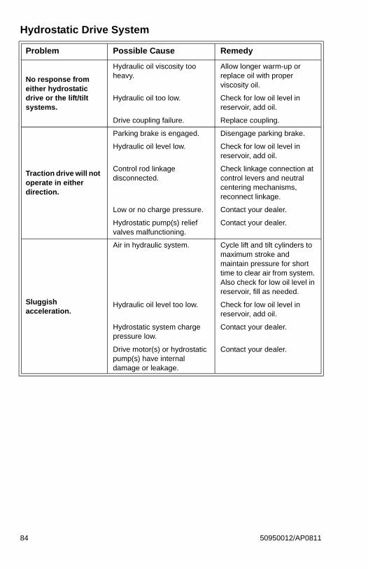
Hydrostatic Drive System
Problem Possible Cause Remedy
No response from either hydrostatic drive or the lift/tilt systems.
Hydraulic oil viscosity too heavy.
Allow longer warm-up or replace oil with proper viscosity oil.
Hydraulic oil too low. Check for low oil level in reservoir, add oil.
Drive coupling failure. Replace coupling.
Traction drive will not operate in either direction.
Parking brake is engaged. Disengage parking brake.
Hydraulic oil level low. Check for low oil level in reservoir, add oil.
Control rod linkage disconnected.
Check linkage connection at control levers and neutral centering mechanisms, reconnect linkage.
Low or no charge pressure. Contact your dealer.
Hydrostatic pump(s) relief valves malfunctioning.
Contact your dealer.
Sluggish acceleration.
Air in hydraulic system. Cycle lift and tilt cylinders to maximum stroke and maintain pressure for short time to clear air from system. Also check for low oil level in reservoir, fill as needed.
Hydraulic oil level too low. Check for low oil level in reservoir, add oil.
Hydrostatic system charge pressure low.
Contact your dealer.
Drive motor(s) or hydrostatic pump(s) have internal damage or leakage.
Contact your dealer.
84 50950012/AP0811
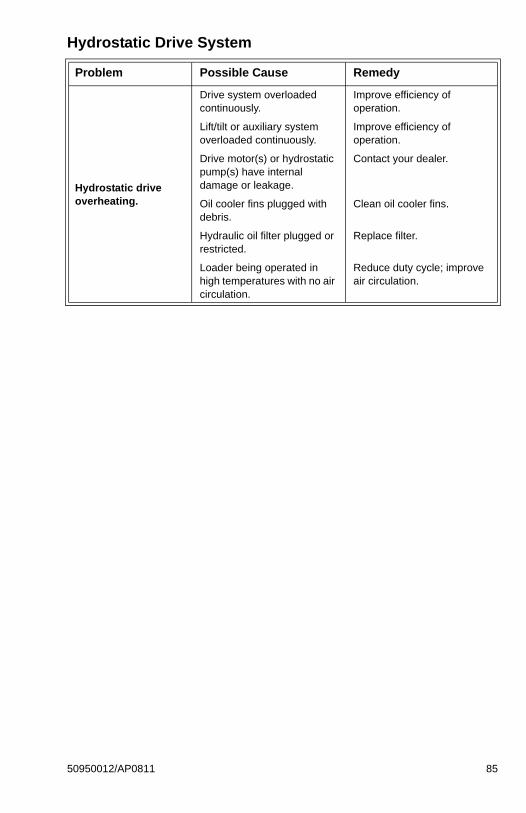
Hydrostatic drive overheating.
Drive system overloaded continuously.
Improve efficiency of operation.
Lift/tilt or auxiliary system overloaded continuously.
Improve efficiency of operation.
Drive motor(s) or hydrostatic pump(s) have internal damage or leakage.
Contact your dealer.
Oil cooler fins plugged with debris.
Clean oil cooler fins.
Hydraulic oil filter plugged or restricted.
Replace filter.
Loader being operated in high temperatures with no air circulation.
Reduce duty cycle; improve air circulation.
Hydrostatic Drive System
Problem Possible Cause Remedy
50950012/AP0811 85
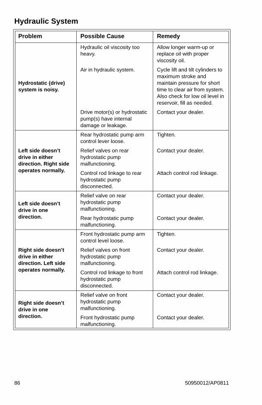
Hydraulic System
Problem Possible Cause Remedy
Hydrostatic (drive) system is noisy.
Hydraulic oil viscosity too heavy.
Allow longer warm-up or replace oil with proper viscosity oil.
Air in hydraulic system. Cycle lift and tilt cylinders to maximum stroke and maintain pressure for short time to clear air from system. Also check for low oil level in reservoir, fill as needed.
Drive motor(s) or hydrostatic pump(s) have internal damage or leakage.
Contact your dealer.
Left side doesn’t drive in either direction. Right side operates normally.
Rear hydrostatic pump arm control lever loose.
Tighten.
Relief valves on rear hydrostatic pump malfunctioning.
Contact your dealer.
Control rod linkage to rear hydrostatic pump disconnected.
Attach control rod linkage.
Left side doesn’t drive in one direction.
Relief valve on rear hydrostatic pump malfunctioning.
Contact your dealer.
Rear hydrostatic pump malfunctioning.
Contact your dealer.
Right side doesn’t drive in either direction. Left side operates normally.
Front hydrostatic pump arm control level loose.
Tighten.
Relief valves on front hydrostatic pump malfunctioning.
Contact your dealer.
Control rod linkage to front hydrostatic pump disconnected.
Attach control rod linkage.
Right side doesn’t drive in one direction.
Relief valve on front hydrostatic pump malfunctioning.
Contact your dealer.
Front hydrostatic pump malfunctioning.
Contact your dealer.
86 50950012/AP0811
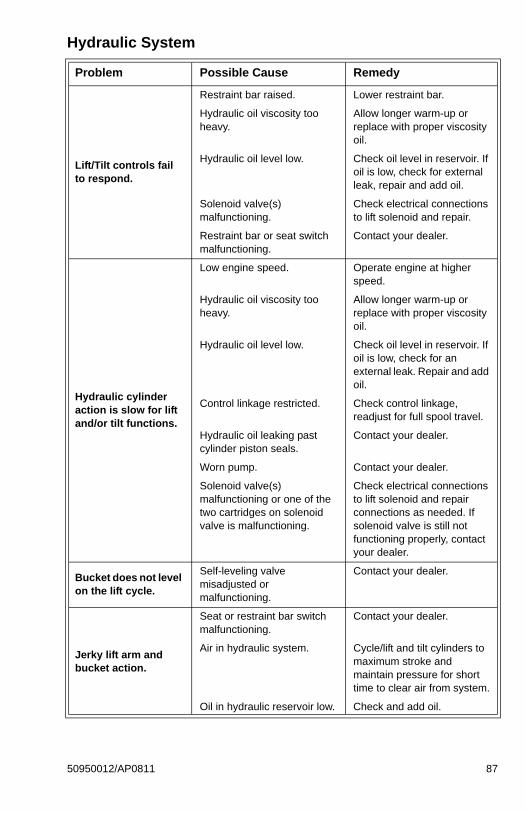
Lift/Tilt controls fail to respond.
Restraint bar raised. Lower restraint bar.
Hydraulic oil viscosity too heavy.
Allow longer warm-up or replace with proper viscosity oil.
Hydraulic oil level low. Check oil level in reservoir. If oil is low, check for external leak, repair and add oil.
Solenoid valve(s) malfunctioning.
Check electrical connections to lift solenoid and repair.
Restraint bar or seat switch malfunctioning.
Contact your dealer.
Hydraulic cylinder action is slow for lift and/or tilt functions.
Low engine speed. Operate engine at higher speed.
Hydraulic oil viscosity too heavy.
Allow longer warm-up or replace with proper viscosity oil.
Hydraulic oil level low. Check oil level in reservoir. If oil is low, check for an external leak. Repair and add oil.
Control linkage restricted. Check control linkage, readjust for full spool travel.
Hydraulic oil leaking past cylinder piston seals.
Contact your dealer.
Worn pump. Contact your dealer.
Solenoid valve(s) malfunctioning or one of the two cartridges on solenoid valve is malfunctioning.
Check electrical connections to lift solenoid and repair connections as needed. If solenoid valve is still not functioning properly, contact your dealer.
Bucket does not level on the lift cycle.
Self-leveling valve misadjusted or malfunctioning.
Contact your dealer.
Jerky lift arm and bucket action.
Seat or restraint bar switch malfunctioning.
Contact your dealer.
Air in hydraulic system. Cycle/lift and tilt cylinders to maximum stroke and maintain pressure for short time to clear air from system.
Oil in hydraulic reservoir low. Check and add oil.
Hydraulic System
Problem Possible Cause Remedy
50950012/AP0811 87
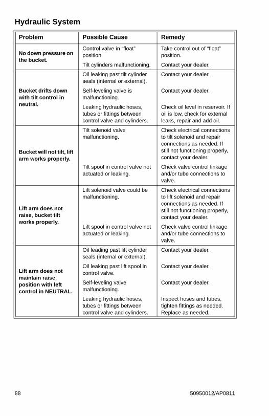
No down pressure on the bucket.
Control valve in “float” position.
Take control out of “float” position.
Tilt cylinders malfunctioning. Contact your dealer.
Bucket drifts down with tilt control in neutral.
Oil leaking past tilt cylinder seals (internal or external).
Contact your dealer.
Self-leveling valve is malfunctioning.
Contact your dealer.
Leaking hydraulic hoses, tubes or fittings between control valve and cylinders.
Check oil level in reservoir. If oil is low, check for external leaks, repair and add oil.
Bucket will not tilt, lift arm works properly.
Tilt solenoid valve malfunctioning.
Check electrical connections to tilt solenoid and repair connections as needed. If still not functioning properly, contact your dealer.
Tilt spool in control valve not actuated or leaking.
Check valve control linkage and/or tube connections to valve.
Lift arm does not raise, bucket tilt works properly.
Lift solenoid valve could be malfunctioning.
Check electrical connections to lift solenoid and repair connections as needed. If still not functioning properly, contact your dealer.
Lift spool in control valve not actuated or leaking.
Check valve control linkage and/or tube connections to valve.
Lift arm does not maintain raise position with left control in NEUTRAL.
Oil leading past lift cylinder seals (internal or external).
Contact your dealer.
Oil leaking past lift spool in control valve.
Contact your dealer.
Self-leveling valve malfunctioning.
Contact your dealer.
Leaking hydraulic hoses, tubes or fittings between control valve and cylinders.
Inspect hoses and tubes, tighten fittings as needed. Replace as needed.
Hydraulic System
Problem Possible Cause Remedy
88 50950012/AP0811
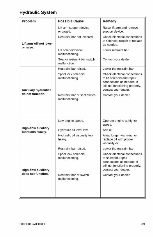
Lift arm will not lower or raise.
Lift arm support device engaged.
Raise lift arm and remove support device.
Restraint bar not lowered. Check electrical connections to solenoid. Repair or replace as needed.
Lift solenoid valve malfunctioning.
Lower restraint bar.
Seat or restraint bar switch malfunction.
Contact your dealer.
Auxiliary hydraulics do not function.
Restraint bar raised. Lower the restraint bar.
Spool lock solenoid malfunctioning.
Check electrical connections to lift solenoid and repair connections as needed. If still not functioning properly, contact your dealer.
Restraint bar or seat switch malfunctioning.
Contact your dealer.
High-flow auxiliary functions slowly.
Low engine speed. Operate engine at higher speed.
Hydraulic oil level low. Add oil.
Hydraulic oil viscosity too heavy.
Allow longer warm-up, or replace oil with proper viscosity oil.
High-flow auxiliary does not function.
Restraint bar raised. Lower the restraint bar.
Spool lock solenoid malfunctioning.
Check electrical connections to solenoid, repair connections as needed. If still not functioning properly, contact your dealer.
Restraint bar or switch malfunctioning.
Contact your dealer.
Hydraulic System
Problem Possible Cause Remedy
50950012/AP0811 89

90 50950012/AP0811
Notes
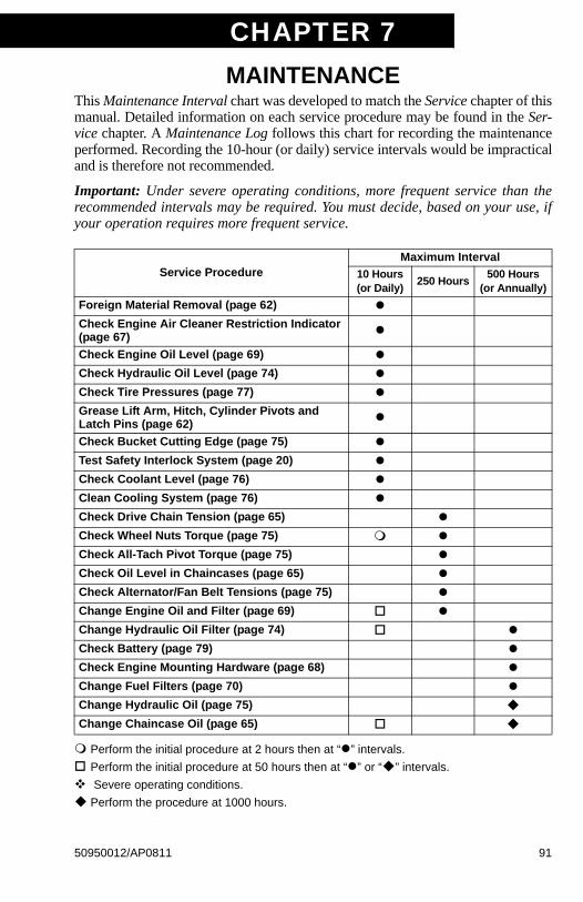
CHAPTER 7MAINTENANCE
This Maintenance Interval chart was developed to match the Service chapter of thismanual. Detailed information on each service procedure may be found in the Ser-vice chapter. A Maintenance Log follows this chart for recording the maintenanceperformed. Recording the 10-hour (or daily) service intervals would be impracticaland is therefore not recommended.
Important: Under severe operating conditions, more frequent service than therecommended intervals may be required. You must decide, based on your use, ifyour operation requires more frequent service.
Service ProcedureMaximum Interval
10 Hours (or Daily)
250 Hours500 Hours
(or Annually)
Foreign Material Removal (page 62) Check Engine Air Cleaner Restriction Indicator (page 67)
Check Engine Oil Level (page 69) Check Hydraulic Oil Level (page 74) Check Tire Pressures (page 77) Grease Lift Arm, Hitch, Cylinder Pivots and Latch Pins (page 62)
Check Bucket Cutting Edge (page 75) Test Safety Interlock System (page 20) Check Coolant Level (page 76) Clean Cooling System (page 76) Check Drive Chain Tension (page 65) Check Wheel Nuts Torque (page 75) Check All-Tach Pivot Torque (page 75) Check Oil Level in Chaincases (page 65) Check Alternator/Fan Belt Tensions (page 75) Change Engine Oil and Filter (page 69) Change Hydraulic Oil Filter (page 74) Check Battery (page 79) Check Engine Mounting Hardware (page 68) Change Fuel Filters (page 70) Change Hydraulic Oil (page 75) Change Chaincase Oil (page 65)
Perform the initial procedure at 2 hours then at “” intervals.
Perform the initial procedure at 50 hours then at “” or “” intervals.
Severe operating conditions.
Perform the procedure at 1000 hours.
50950012/AP0811 91

Maintenance Log
Date Hours Service Procedure
92 50950012/AP0811

Maintenance Log
Date Hours Service Procedure
50950012/AP0811 93

Maintenance Log
Date Hours Service Procedure
94 50950012/AP0811
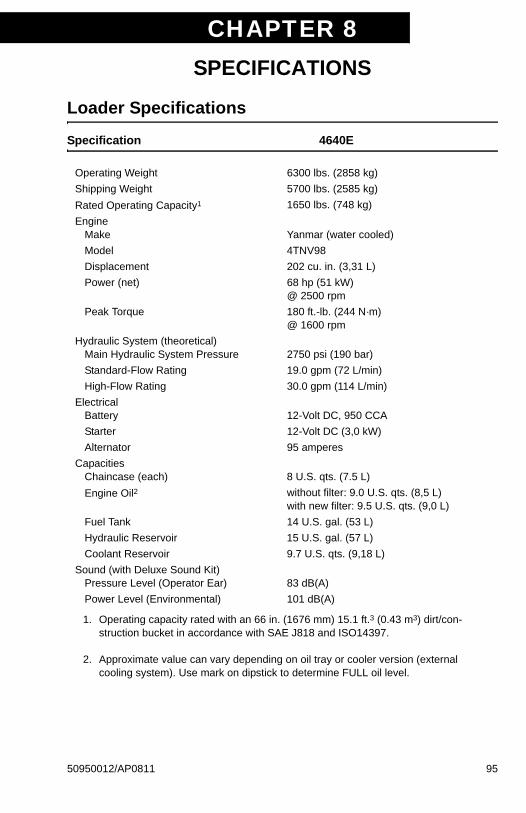
CHAPTER 8SPECIFICATIONS
Loader Specifications
Specification 4640E
Operating Weight 6300 lbs. (2858 kg)
Shipping Weight 5700 lbs. (2585 kg)
Rated Operating Capacity1
1. Operating capacity rated with an 66 in. (1676 mm) 15.1 ft.3 (0.43 m3) dirt/con-struction bucket in accordance with SAE J818 and ISO14397.
2. Approximate value can vary depending on oil tray or cooler version (external cooling system). Use mark on dipstick to determine FULL oil level.
1650 lbs. (748 kg)
EngineMake Yanmar (water cooled)
Model 4TNV98
Displacement 202 cu. in. (3,31 L)
Power (net) 68 hp (51 kW)@ 2500 rpm
Peak Torque 180 ft.-lb. (244 N·m)@ 1600 rpm
Hydraulic System (theoretical) Main Hydraulic System Pressure 2750 psi (190 bar)
Standard-Flow Rating 19.0 gpm (72 L/min)
High-Flow Rating 30.0 gpm (114 L/min)
ElectricalBattery 12-Volt DC, 950 CCA
Starter 12-Volt DC (3,0 kW)
Alternator 95 amperes
CapacitiesChaincase (each) 8 U.S. qts. (7.5 L)
Engine Oil2 without filter: 9.0 U.S. qts. (8,5 L)with new filter: 9.5 U.S. qts. (9,0 L)
Fuel Tank 14 U.S. gal. (53 L)
Hydraulic Reservoir 15 U.S. gal. (57 L)
Coolant Reservoir 9.7 U.S. qts. (9,18 L)
Sound (with Deluxe Sound Kit)Pressure Level (Operator Ear) 83 dB(A)
Power Level (Environmental) 101 dB(A)
50950012/AP0811 95
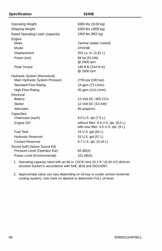
Specification 5240E
Operating Weight 6900 lbs (3130 kg)
Shipping Weight 6300 lbs (2858 kg)
Rated Operating Load1 (capacity)
1. Operating capacity rated with an 66 in. (1676 mm) 15.1 ft.3 (0.43 m3) dirt/con-struction bucket in accordance with SAE J818 and ISO14397.
2. Approximate value can vary depending on oil tray or cooler version (external cooling system). Use mark on dipstick to determine FULL oil level.
1900 lbs (862 kg)
EngineMake Yanmar (water cooled)
Model 4TNV98
Displacement 202 cu. in. (3,31 L)
Power (net) 68 hp (51 kW)@ 2500 rpm
Peak Torque 180 ft-lb (244 N·m)@ 1600 rpm
Hydraulic System (theoretical) Main Hydraulic System Pressure 2750 psi (190 bar)
Standard-Flow Rating 19 gpm (72 L/min)
High-Flow Rating 30 gpm (114 L/min)
ElectricalBattery 12-Volt DC, 950 CCA
Starter 12-Volt DC (3,0 kW)
Alternator 95 amperes
CapacitiesChaincase (each) 8.0 U.S. qts (7.5 L)
Engine Oil2 without filter: 9.0 U.S. qts. (8,5 L)with new filter: 9.5 U.S. qts. (9 L)
Fuel Tank 16 U.S. gal (60 L)
Hydraulic Reservoir 15 U.S. gal (57 L)
Coolant Reservoir 9.7 U.S. qts. (9,18 L)
Sound (with Deluxe Sound Kit)Pressure Level (Operator Ear) 83 dB(A)
Power Level (Environmental) 101 dB(A)
96 50950012/AP0811
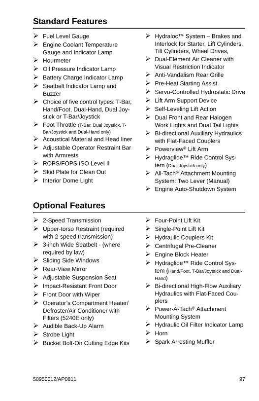
Standard Features
Fuel Level Gauge
Engine Coolant Temperature Gauge and Indicator Lamp
Hourmeter
Oil Pressure Indicator Lamp
Battery Charge Indicator Lamp
Seatbelt Indicator Lamp and Buzzer
Choice of five control types: T-Bar, Hand/Foot, Dual-Hand, Dual Joy-stick or T-Bar/Joystick
Foot Throttle (T-Bar, Dual Joystick, T-
Bar/Joystick and Dual-Hand only)
Acoustical Material and Head liner
Adjustable Operator Restraint Bar with Armrests
ROPS/FOPS ISO Level II
Skid Plate for Clean Out
Interior Dome Light
Hydraloc™ System – Brakes and Interlock for Starter, Lift Cylinders, Tilt Cylinders, Wheel Drives,
Dual-Element Air Cleaner with Visual Restriction Indicator
Anti-Vandalism Rear Grille
Pre-Heat Starting Assist
Servo-Controlled Hydrostatic Drive
Lift Arm Support Device
Self-Leveling Lift Action
Dual Front and Rear Halogen Work Lights and Dual Tail Lights
Bi-directional Auxiliary Hydraulics with Flat-Faced Couplers
Powerview® Lift Arm
Hydraglide™ Ride Control Sys-tem (Dual Joystick only)
All-Tach® Attachment Mounting System: Two Lever (Manual)
Engine Auto-Shutdown System
Optional Features
2-Speed Transmission
Upper-torso Restraint (required with 2-speed transmission)
3-inch Wide Seatbelt - (where required by law)
Sliding Side Windows
Rear-View Mirror
Adjustable Suspension Seat
Impact-Resistant Front Door
Front Door with Wiper
Operator’s Compartment Heater/Defroster/Air Conditioner with Filters (5240E only)
Audible Back-Up Alarm
Strobe Light
Bucket Bolt-On Cutting Edge Kits
Four-Point Lift Kit
Single-Point Lift Kit
Hydraulic Couplers Kit
Centrifugal Pre-Cleaner
Engine Block Heater
Hydraglide™ Ride Control Sys-tem (Hand/Foot, T-Bar/Joystick and Dual-
Hand) Bi-directional High-Flow Auxiliary
Hydraulics with Flat-Faced Cou-plers
Power-A-Tach® Attachment Mounting System
Hydraulic Oil Filter Indicator Lamp
Horn
Spark Arresting Muffler
50950012/AP0811 97
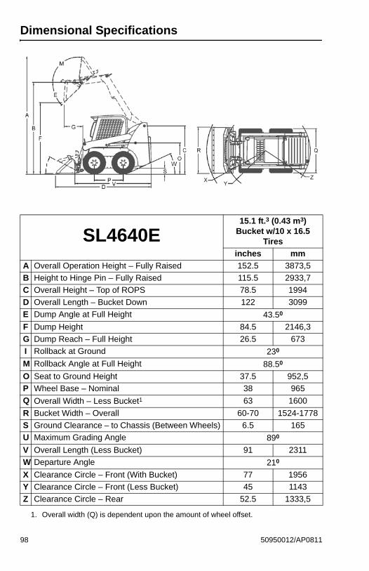
Dimensional Specifications
SL4640E15.1 ft.3 (0.43 m3)
Bucket w/10 x 16.5 Tires
inches mm
A Overall Operation Height – Fully Raised 152.5 3873,5
B Height to Hinge Pin – Fully Raised 115.5 2933,7
C Overall Height – Top of ROPS 78.5 1994
D Overall Length – Bucket Down 122 3099
E Dump Angle at Full Height 43.50
F Dump Height 84.5 2146,3
G Dump Reach – Full Height 26.5 673
I Rollback at Ground 230
M Rollback Angle at Full Height 88.50
O Seat to Ground Height 37.5 952,5
P Wheel Base – Nominal 38 965
Q Overall Width – Less Bucket1 63 1600
R Bucket Width – Overall 60-70 1524-1778
S Ground Clearance – to Chassis (Between Wheels) 6.5 165
U Maximum Grading Angle 890
V Overall Length (Less Bucket) 91 2311
W Departure Angle 210
X Clearance Circle – Front (With Bucket) 77 1956
Y Clearance Circle – Front (Less Bucket) 45 1143
Z Clearance Circle – Rear 52.5 1333,5
1. Overall width (Q) is dependent upon the amount of wheel offset.
98 50950012/AP0811
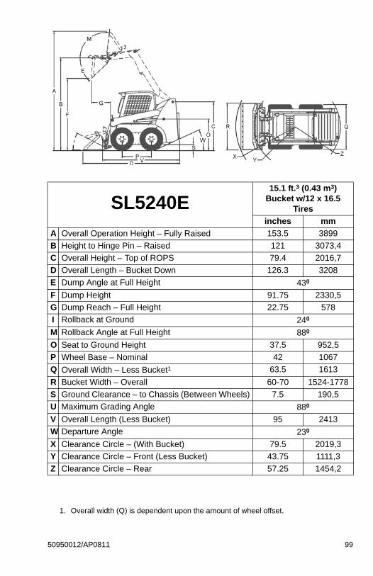
SL5240E15.1 ft.3 (0.43 m3)
Bucket w/12 x 16.5 Tires
inches mm
A Overall Operation Height – Fully Raised 153.5 3899
B Height to Hinge Pin – Raised 121 3073,4
C Overall Height – Top of ROPS 79.4 2016,7
D Overall Length – Bucket Down 126.3 3208
E Dump Angle at Full Height 430
F Dump Height 91.75 2330,5
G Dump Reach – Full Height 22.75 578
I Rollback at Ground 240
M Rollback Angle at Full Height 880
O Seat to Ground Height 37.5 952,5
P Wheel Base – Nominal 42 1067
Q Overall Width – Less Bucket1 63.5 1613
R Bucket Width – Overall 60-70 1524-1778
S Ground Clearance – to Chassis (Between Wheels) 7.5 190,5
U Maximum Grading Angle 880
V Overall Length (Less Bucket) 95 2413
W Departure Angle 230
X Clearance Circle – (With Bucket) 79.5 2019,3
Y Clearance Circle – Front (Less Bucket) 43.75 1111,3
Z Clearance Circle – Rear 57.25 1454,2
1. Overall width (Q) is dependent upon the amount of wheel offset.
50950012/AP0811 99
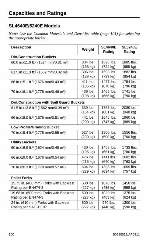
Capacities and Ratings
SL4640E/5240E Models
Note: Use the Common Materials and Densities table (page 101) for selectingthe appropriate bucket.
DescriptionWeight
SL4640E Rating
SL5240E Rating
Dirt/Construction Buckets
60.0 in./11.0 ft.3 (1524 mm/0.31 m3) 304 lbs.(138 kg)
1596 lbs.(724 kg)
1885 lbs.(855 kg)
61.5 in./11.3 ft.3 (1562 mm/0.32 m3) 306 lbs.(139 kg)
1593 lbs.(723 kg)
1882 lbs.(854 kg)
66 in./15.1 ft.3 (1676 mm/0.43 m3) 411 lbs.(186 kg)
1477 lbs.(670 kg)
1754 lbs. (796 kg)
70 in./16.1 ft.3 (1778 mm/0.46 m3) 436 lbs.(198 kg)
1465 lbs.(665 kg)
1741 lbs. (790 kg)
Dirt/Construction with Spill Guard Buckets
61.5 in./13.8 ft.3 (1562 mm/0.39 m3) 339 lbs.(154 kg)
1767 lbs.(801 kg)
2089 lbs. (948 kg)
66 in./18.0 ft.3 (1676 mm/0.51 m3) 441 lbs.(200 kg)
1646 lbs.(747 kg)
1960 lbs. (889 kg)
Low Profile/Grading Bucket
70 in./19.4 ft.3 (1778 mm/0.55 m3) 527 lbs.(239 kg)
1300 lbs.(590 kg)
1556 lbs.(706 kg)
Utility Buckets
60 in./16.9 ft.3 (1524 mm/0.48 m3) 430 lbs.(195 kg)
1458 lbs.(661 kg)
1733 lbs.(786 kg)
66 in./19.0 ft.3 (1676 mm/0.54 m3) 476 lbs.(216 kg)
1411 lbs.(640 kg)
1682 lbs.(763 kg)
70 in./20.3 ft.3 (1778 mm/0.57 m3) 504 lbs.(229 kg)
1398 lbs.(634 kg)
1669 lbs.(757 kg)
Pallet Forks
15.75 in. (400 mm) Forks with Backrest Rating per EN474-3
500 lbs.(227 kg)
1070 lbs.(485 kg)
1450 lbs. (658 kg)
19.68 in. (500 mm) Forks with Backrest Rating per EN474-3
500 lbs.(227 kg)
1020 lbs.(463 kg)
1375 lbs. (624 kg)
24 in. (610 mm) Forks with Backrest Rating per SAE J1197
500 lbs.(227 kg)
970 lbs.(440 kg)
1300 lbs. (590 kg)
100 50950012/AP0811

Common Materials and Densities
Note: The densities listed are average values and intended only as a guide forbucket selection. For a material that is not in the table, obtain its density valuebefore selecting the appropriate bucket.
MaterialDensity
lbs./ft.3 kg/m3
Ashes 35-50 560-800
Brick-common 112 1792
Cement 110 1760
Charcoal 23 368
Clay, wet-dry 80-100 1280-1600
Coal 53-63 848-1008
Concrete 115 1840
Cinders 50 800
Coal-anthracite 94 1504
Coke 30 480
Earth-dry loam 70-90 1121-1442
Earth-wet loam 80-100 1281-1602
Granite 93-111 1488-1776
Gravel-dry 100 1602
Gravel-wet 120 1922
Gypsum-crushed 115 1840
Iron ore 145 2320
Lime 60 960
Lime stone 90 1440
Manure-liquid 65 1040
Manure-solid 45 720
Peat-solid 47 752
Phosphate-granular 90 1440
Potash 68 1088
Quartz-granular 110 1760
Salt-dry 100 1602
Salt-rock-solid 135 2160
Sand-dry 108 1728
Sand-wet 125 2000
Sand-foundry 95 1520
Shale-crushed 90 1440
Slag-crushed 70 1120
Snow 15-50 240-800
Taconite 107 1712
50950012/AP0811 101
Bucket Selection
To use the table, find the material to be loaded and read its maximum density.Then multiply the volumetric rating of the attachment by the material density todetermine if the attachment can safely be used. See page 100 for a listing ofattachments and their capacity ratings.
Note: Where the material density is listed as a range (clay at 80-100 lbs./ft.3, forexample), always use the maximum density (100 lbs./ft.3 in this example) formaking calculations. Also, see the following examples.
Example 1: If clay (density of 80-100 lbs./ft.3) is to be hauled using a SL4640Emodel loader using a 15.1 ft.3 Dirt/Construction bucket, the bucket capacity is15.1 ft.3 and the loader rating is 1650 lbs. Multiply the density of clay (100 lbs/ft.3) by the capacity of the bucket (15.1 ft.3) to determine the weight to be carried(100 lbs./ft.3 x 15.1 ft.3 = 1510 lbs.). This number is less than the machine rating,allowing safe use of this bucket in this application.
Example 2: If dry sand (density of 1728 kg/m3) is to be hauled using a SL4640Emodel loader using a 0.43 m3 Dirt/Construction bucket, the bucket capacity is0.43 m3 and the loader rating is 748 kg. Multiply the density of dry sand (1728kg/m3) by the capacity of the bucket (0.43 m3) to determine the weight to be car-ried (1728 kg/m3 x 0.43 m3 = 743 kg). This number is less than the machinerating, allowing safe use of this bucket in this application.
102 50950012/AP0811
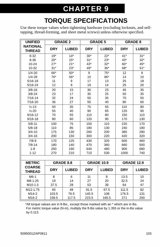
CHAPTER 9TORQUE SPECIFICATIONS
Use these torque values when tightening hardware (excluding locknuts, and self-tapping, thread-forming, and sheet metal screws) unless otherwise specified.
*All torque values are in ft-lbs., except those marked with an * which are in lbs. For metric torque value (N·m), multiply the ft-lbs value by 1.355 or the in-lbs value by 0.113.
UNIFIEDNATIONALTHREAD
GRADE 2 GRADE 5 GRADE 8
DRY LUBED DRY LUBED DRY LUBED
8-328-36
10-2410-32
19*20*27*31*
14*15*21*23*
30*31*43*49*
22*23*32*36*
41*43*60*68*
31*32*45*51*
1/4-201/4-28
5/16-185/16-24
66*76*1112
50*56*99
9101719
75*86*1314
12142525
9101820
3/8-163/8-24
7/16-147/16-20
20233236
15172427
30355055
23253540
45507080
35355560
½-13½-20
9/16-129/16-18
50557080
35405560
7590110120
55658090
110120150170
8090110130
5/8-115/8-183/4-103/4-16
100110175200
7585
130150
150180260300
110130200220
220240380420
170180280320
7/8-97/8-14
1-81-12
170180250270
125140190210
430470640710
320360480530
600660900
1000
460500680740
METRICCOARSETHREAD
GRADE 8.8 GRADE 10.9 GRADE 12.9
DRY LUBED DRY LUBED DRY LUBED
M6-1M8-1.25M10-1.5
819
37.5
61428
112753
82039
13.532.564
102447
M12-1.75M14-2M16-2
65103.5158.5
4876.5117.5
91.5145.5223.5
67.5108
165.5
111.5176.5271
82131200
50950012/AP0811 103

GEHL COMPANY
WARRANTYGEHL COMPANY, hereinafter referred to as Gehl, warrants newGehl equipment to the Original Retail Purchaser to be free fromdefects in material and workmanship for a period of twelve (12)months from the Warranty Start Date.
GEHL WARRANTY SERVICE INCLUDES:
Genuine Gehl parts and labor costs required to repair or replaceequipment at the selling dealer’s business location.
GEHL MAKES NO REPRESENTATIONS OR WARRANTIES OFANY KIND, EXPRESS OR IMPLIED (INCLUDING THE IMPLIEDWARRANTIES OF MERCHANTABILITY AND FITNESS FORPARTICULAR PURPOSE), EXCEPT AS EXPRESSLY STATEDIN THIS WARRANTY STATEMENT.
ANY OF THESE LIMITATIONS EXCLUDED BY LOCAL LAWSHALL BE DEEMED DELETED FROM THIS WARRANTY; ALLOTHER TERMS WILL CONTINUE TO APPLY.
SOME STATES DO NOT PERMIT THE EXCLUSION ORLIMITATION OF THESE WARRANTIES AND YOU HAVEGREATER RIGHTS UNDER THE STATE LAW.
GEHL WARRANTY DOES NOT INCLUDE:1. Transportation to selling dealer’s business location or, at the
option of the Original Retail Purchaser, the cost of a service call.2. Used equipment.3. Components covered by their own non-Gehl warranties, such
as tires, batteries, trade accessories and engines.4. Normal maintenance service and expendable, high-wear items.5. Repairs or adjustments caused by: improper use; failure to follow
recommended maintenance procedures; use of unauthorizedparts or attachments; accident or other casualty.
6. Liability for incidental or consequential damages of any type,including, but not limited to lost profits and expenses of acquiringreplacement equipment.
No agent, employee or representative of Gehl has any authority tobind Gehl to any warranty except as specifically set forth herein.
104 50950012/AP0811
INDEX
AAccessory Plug . . . . . . . . . . . . . 23
Adjustments. . . . . . . . . . . . . . . . 61
Control Handles. . . . . . . . . . 61
Fuel Sender . . . . . . . . . . . . . 61
Air Conditioner
Operation. . . . . . . . . . . . . . . 24
Alternator/Fan Belt . . . . . . . . . . 75
Attachment Mounting . . . . . . . . 27
All-Tach® Hitch . . . . . . . . . . 27
Power-A-Tach® Hitch . . . . . 27
Attachments, Changing . . . . . . . 46
Auto-Shutdown . . . . . . . . . . . . . 26
Auxiliary Hydraulic Controls
High-Flow . . . . . . . . . . . . . . 41
Standard Flow . . . . . . . . . . . 40
BBattery . . . . . . . . . . . . . . . . . . . . 79
Jump-starting. . . . . . . . . . . . 45
Before Starting the Engine
Cold-Starting . . . . . . . . . . . . . 44
Cold-Starting Procedure . . . 44
Bucket Cutting Edge . . . . . . . . . 75
Bucket Selection . . . . . . . . . . . 102
Bucket, Usage. . . . . . . . . . . . . . 48
Digging with a Bucket . . . . . 48
Driving on an Incline . . . . . . 48
Driving over Rough Terrain . . . . . . . . . . . . . . . 48
Dumping into a Truck or Hopper . . . . . . . . 49
Dumping Onto a Pile . . . . . . 49
Dumping Over an Embankment . . . . . . . . 49
Leveling the Ground . . . . . . 50
Loading a Bucket. . . . . . . . . 49
Scraping with a Bucket . . . . 50
CChaincases . . . . . . . . . . . . . . . . . 65
Checking and Adding Oil. . . . . . . . . . . . . . 65
Draining Oil . . . . . . . . . . . . . . 65
Changing Attachments
Connecting Attachments . . . . 46
Removing Attachments . . . . . 47
Changing Hydraulic Oil . . . . . . . . 75
Changing HydraulicOil Filter . . . . . . . . . . . . . . . . . . 74
Chart, Diagnostic
Engine. . . . . . . . . . . . . . . . . . 70
Checking and Adding Oil . . . . . . 65
Checking HydraulicOil Level . . . . . . . . . . . . . . . . . . 74
Checking Tire Pressure . . . . . . . 77
Cleaning the Cooling System . . . . . . . . . . . . . . . . . . 76
Cold Starting Procedure 44
Common Materials and Densities . . . . . . . . . . . . . . . . 101
Connecting AuxiliaryHydraulic Couplings . . . . . . . . . 47
Control/Indicator Symbols. . . . . . . 4
Controls and SafetyEquipment Chapter . . . . . . . . . 19
Cooling System. . . . . . . . . . . . . . 76
Cleaning . . . . . . . . . . . . . . . . 76
DDealer Services. . . . . . . . . . . . . . 57
Dimensional Specifications. . . . . 98
Dome Light . . . . . . . . . . . . . . . . . 23
Draining Oil . . . . . . . . . . . . . . . . . 65
Drive Chains
Adjusting Chain Tension . . . . 65
Checking Chain Tension . . . . 65
Dual Hand Controls. . . . . . . . . . . 39
Auxiliary Hydraulic
50950012/AP0811 105
Controls . . . . . . . . . . . . . . . 40
Drive Control . . . . . . . . . . . . . 39
Lift/Tilt Control . . . . . . . . . . . . 39
Dual Joystick Controls . . . . . . . . 35
Drive Controls . . . . . . . . . . . . 35
Lift/Tilt Controls . . . . . . . . . . . 36
EElectrical System . . . . . . . . . . . . 78
Fuse Panel . . . . . . . . . . . . . . 78
Emergency Exit. . . . . . . . . . . . . . 22
Engine Air Cleaner . . . . . . . . . . . 67
Changing Air CleanerElements . . . . . . . . . . . . . . 67
Engine Auto-Shutdown . . . . . . . . 26
Engine CompartmentAccess . . . . . . . . . . . . . . . . . . . 60
Engine Diagnostic Chart . . . . . . . 70
Engine Service
Changing Engine Oiland Filter . . . . . . . . . . . . . . 69
Changing Main Fuel Filter . . . 70
Checking EngineMounting Hardware . . . . . . 68
Checking Oil Level . . . . . . . . 69
Engine Speed Control. . . . . . . . . 25
FForeign Material Removal. . . . . . 62
Fuse Panel . . . . . . . . . . . . . . . . . 78
GGuards and Shields . . . . . . . . . . 19
HHand/Foot Controls. . . . . . . . . . . 37
Auxiliary Hydraulic Controls . . . . . . . . . . . . . . . 40
Drive Controls . . . . . . . . . . . . 37
Lift/Tilt Controls . . . . . . . . . . 38
Heater
Filter Service . . . . . . . . . . . . . 77
Operation . . . . . . . . . . . . . . . 24
Heater and Air Conditioner
Operation . . . . . . . . . . . . . . . 24
Heater Filters . . . . . . . . . . . . . . . 77
Highway Travel. . . . . . . . . . . . . . 54
Horn . . . . . . . . . . . . . . . . . . . . . . 21
Hydraglide™ RideControl System . . . . . . . . . . . . 26
Hydraloc™ System. . . . . . . . . . . 20
Hydraulic System . . . . . . . . . . . . 74
Changing Hydraulic Oil . . . . . 75
Changing HydraulicOil Filter . . . . . . . . . . . . . . 74
Checking Oil Level . . . . . . . . 74
IInstrument Panel . . . . . . . . . . . . 28
Instrument Panels . . . . . . . . . . . 28
Left Instrument Panel . . . . . . 28
Right Instrument Panel . . . . . 29
Introduction. . . . . . . . . . . . . . . . . . 1
LLift Arm Pivots . . . . . . . . . . . . . . 75
Lift Arm Support Device . . . . . . . 22
Disengagement . . . . . . . . . . 23
Engagement . . . . . . . . . . . . . 22
Lifting the Loader . . . . . . . . . . . . 56
Loader
Lifting . . . . . . . . . . . . . . . . . . 56
Lowering Procedure . . . . . . . 60
Raising Procedure . . . . . . . . 59
Removing from Storage . . . . 54
Storing . . . . . . . . . . . . . . . . . 54
Transporting . . . . . . . . . . . . . 55
Loader Identification . . . . . . . . . . . 3
Loader Specifications . . . . . . . . . 95
Lubrication . . . . . . . . . . . . . . . . . 62
106 50950012/AP0811
MMaintenance Chapter . . . . . . . . 91
Maintenance Schedule
Maintenance IntervalChart . . . . . . . . . . . . . . . . . 91
Maintenance Log . . . . . . . . . 92
Mandatory Safety Shutdown Procedure. . . . . . . . . . . . . . . . . 6
OOperation
Jump-Starting . . . . . . . . . . . 45
Parking the Loader . . . . . . . 44
Stopping the Loader . . . . . . 44
Operation Chapter. . . . . . . . . . . 43
Operator Restraint Bar . . . . . . . 19
Operator’s Seat . . . . . . . . . . . . . 20
Optional Features . . . . . . . . . . . 97
PParking Brake . . . . . . . . . . . . . . 21
Parking the Loader . . . . . . . . . . 44
Potential Hazards . . . . . . . . . . . . 8
Product and ComponentPlate Locations. . . . . . . . . . . . 17
RRemoving Loader from Storage 54
Replacement Parts . . . . . . . . . . 58
Ride Control System . . . . . . . . . 26
ROPS/FOPS . . . . . . . . . . . . . . . 21
Tilting Back . . . . . . . . . . . . . 61
SSafety Chapter . . . . . . . . . . . . . . 5
Safety Decals . . . . . . . . . . . . . . . 8
New Decal Application. . . . . . 8
No-Text Decals . . . . . . . . . . 13
Text Decals . . . . . . . . . . . . . . 9
Safety Interlock System
Testing. . . . . . . . . . . . . . . . . 20
Safety Reminders . . . . . . . . . . . . 6
Before Starting . . . . . . . . . . . . 6
During Operation. . . . . . . . . . . 7
Maintenance . . . . . . . . . . . . . . 7
Seatbelt
Upper-Torso Restraint. . . . . . 20
Self-Leveling . . . . . . . . . . . . . . . . 48
Service Chapter . . . . . . . . . . . . . 57
Specifications
Dimensional Specifications . . 98
Loader Specifications . . . . . . 95
Optional Features . . . . . . . . . 97
Standard Features . . . . . . . . 97
Specifications Chapter . . . . . . . . 95
Speed Control . . . . . . . . . . . . . . . 25
Standard Features . . . . . . . . . . . 97
Starting the Engine . . . . . . . . . . . 43
Before Starting the Engine . . 43
Stopping the Loader . . . . . . . . . . 44
Storing the Loader . . . . . . . . . . . 54
TT-Bar Controls. . . . . . . . . . . . . . . 31
Auxiliary Hydraulic Controls . . . . . . . . . . . . . . . 40
Drive Controls . . . . . . . . . . . 31
Lift/Tilt Controls . . . . . . . . . . . 32
T-Bar/Joystick Controls. . . . . . . . 33
Drive Controls . . . . . . . . . . . 33
Lift/Tilt Controls . . . . . . . . . . . 34
Tips For Improving Heater Perfor-mance . . . . . . . . . . . . . . . . . . . 24
Tires . . . . . . . . . . . . . . . . . . . . . . 76
Checking Tire Pressure. . . . . 77
Torque Specifications . . . . . . . . 103
Troubleshooting
Electrical . . . . . . . . . . . . . . . . 81
Engine. . . . . . . . . . . . . . . . . . 83
Hydraulic System . . . . . . . . . 86
Hydrostatic Drive System . . . 84
Troubleshooting Chapter . . . . . . 81
Two-Speed Transmission . . . . . . 26
50950012/AP0811 107

VVibration Information. . . . . . . . . . 51
Vibration Levels . . . . . . . . . . . . . 53
Vibration Measurement andActions . . . . . . . . . . . . . . . . . . . 51
WWARRANTY . . . . . . . . . . . . . . . 104
Wheel Nuts . . . . . . . . . . . . . . . . . 75
Work Lights . . . . . . . . . . . . . . . . 23
108 50950012/AP0811
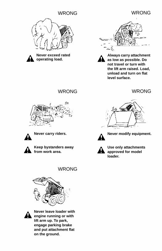
Never exceed rated operating load.
WRONG
Always carry attachment as low as possible. Do not travel or turn with the lift arm raised. Load, unload and turn on flat level surface.
WRONG
Never carry riders.
Keep bystanders away from work area.
WRONG
Never modify equipment.
Use only attachments approved for model loader.
WRONG
Never leave loader with engine running or with lift arm up. To park, engage parking brake and put attachment flat on the ground.
WRONG
WARNING
THIS OPERATOR’S MANUAL IS PROVIDED FOR OPERATOR USE
DO NOT REMOVE FROM THIS MACHINE
Do not start, operate or work on this machine until you care-fully read and thoroughly understand the contents of thisOperator’s Manual.
Failure to follow safety, operating and maintenance instruc-tions can result in serious injury to the operator or bystand-ers, poor operation, and costly breakdowns.
If you have any questions on proper operation, adjustment ormaintenance of this machine, contact your dealer or the GehlService Department before starting or continuing operation.
Manitou Americas, Inc., P.O. Box 179, West Bend, WI 53095-0179 U.S.A.www.gehl.com
California Proposition 65 WarningsDiesel engine exhaust and some of its constituents are known to the State of Californiato cause cancer and birth defects or other reproductive harm.Battery posts, terminals and related accessories contain lead and lead compounds,chemicals known to the State of California to cause cancer and birth defects or otherreproductive harm. Wash hands after handling battery.
®
© 2011 MANITOU AMERICAS, INC. 50950012/AP0811 All Rights Reserved. PRINTED IN U.S.A.