operator's manual - c.searspartsdirect.com€¢ before cleaning, repairing, ... and into the...
TRANSCRIPT

Operator's Manual
Front Tine TillersModels
340 Thru 390
Model 390 Shown
IMPORTANT: Read safety rules and instructions carefully before operating equipment.
Warning: This unit is equipped with an internal combustion engine and should not be used on or near any unimproved forest-covered, brush-covered or grass-covered land unless the engine's exhaust system is equipped with a spark arrester meetingapplicable local or state laws (if any). If a spark arrester is used, it should be maintained in effective working order by the operator.In the State of California the above is required by law (Section 4442 of the California Public Resources Code). Other states may havesimilar laws. Federal laws apply on federal lands. A spark arrester for the muffler is available through your nearest engine authorizedservice dealer or contact the service department, P.O. Box 368022 Cleveland, Ohio 44136-9722.
MTD PRODUCTS INC. P.O. BOX 368022 CLEVELAND, OHIO 44136-9722
PRINTED IN U.S.A. FORM NO. 770-10135A
(12/99)

TABLEOFCONTENTS
Content Page
Important Safe Operation Practices ................................................................... 3, 4
Assembling Your Tiller ....................................................................................... 5
Know Your Tiller ................................................................................................. 7
Operating Your Tiller .......................................................................................... 8
Making Adjustments .......................................................................................... 12
Maintaining Your Tiller ....................................................................................... 13
Off-Season Storage ........................................................................................... 14
Troubleshooting ................................................................................................. 15
Parts List ............................................................................................................ 16
FINDINGMODELNUMBER
This Operator's Manual is an important part of your new tiller. It will help you assemble, prepare andmaintain the unit for best performance. Please read and understand what it says.
Before you start assembling your new equipment, please locate the model plate on theequipment and copy the information from it in the space provided below. The information onthe model plate is very important if you need help from our Customer Support Department oran authorized dealer.
You can locate the model number by standing in the operating position behind the unit and lookingdown at the frame on the right side. A sample model plate is explained below. For future reference,please copy the model number and the serial number of the equipment in the space below.
(Model Number) (Serial Number)
:LEVELAND, OHIO 441_
Copy the model number here:
Copy the serial number here:
CALLINGCUSTOMERSUPPORT
If you have difficulty assembling this product or have any questions regarding the controls, operation ormaintenance of this unit, please call the Customer Support Department.
Call 1- (330) 220-4MTD (4683) or 1- (800)-800-7310 to reach a Customer Supportrepresentative. Please have your unit's model number and serial number ready when youcall. See previous section to locate this information. You will be asked to enter the serialnumber in order to process your call.

SECTION1: IMPORTANTSAFEOPERATIONPRACTICESThis Symbol Points Out Important Safety Instructions Which, If Not Followed, Could Endanger ThePersonal Safety And/or Property Of Yourself And Others. Read And Follow All Instructions In ThisManual Before Attempting To Operate Your Tiller. Failure To Comply With These Instructions MayResult In Personal Injury. When You See This Symbol-- Heed Its Warning.
DANGER: Your tiller was built to be operated according to the rules for safe operation in thismanual. As with any type of power equipment, carelessness or error on the part of the operator canresult in serious injury. This tiller is capable of amputating hands and feet. Failure to observe thefollowing safety instructions could result in serious injury or death.
WARNING: The Engine Exhaust from this product contains chemicals known to the State ofCalifornia to cause cancer, birth defects or other reproductive harm.
GENERALOPERATION• Read this operator's manual carefully in its entirety
before attempting to assemble this machine. Read,understand, and follow all instructions on themachine and in the manual(s) before operation. Becompletely familiar with the controls and the properuse of the machine before operating it. Keep thismanual in a safe place for future and regularreference and for ordering replacement parts.
• Your tiller is a powerful tool, not a plaything.Therefore, exercise extreme caution at all times.Your unit has been designed to perform one job: totill soil. Do not use it for any other purpose.
• Never allow children under age 14 to operate theunit. Children 14 years and older should onlyoperate the unit under close parental supervision.Only responsible individuals who are familiar withthese rules of safe operation should be allowed touse your unit.
• Do not operate tiller while under the influence ofalcohol or drugs.
• Keep the area of operation clear of all persons,particularly small children and pets. Stop the enginewhen they are in the vicinity of your tiller.
• Wear sturdy, rough-soled work shoes and closefitting slacks and shirt. Shirt and slacks that coverthe arms and legs and steel-toed shoes arerecommended. Do not wear loose fitting clothes orjewelry and secure hair so it is above shoulderlength. They can be caught in moving parts. Neveroperate a unit in bare feet, sandals or sneakers.
• Operate tiller only in daylight or good artificial light.• Do not start tiller unless the shift lever (if provided)
is in the neutral (N) position.• Do not allow anyone to stand or walk in front of tiller
when starting or running engine.
• Do not place feet or hands on or near the tineswhen starting the engine or while the engine isrunning.
• Never attempt to make depth bar, tine width, cable,handle, or wheel adjustments while the engine isrunning.
• Do not leave the tiller unattended with the enginerunning.
• Before attempting to remove rocks, bricks andother objects from tines, stop the engine and besu re the tines have stopped completely. Disconnectthe spark plug wire and move it away from thespark plug.
• If your machine should start making an unusualnoise or vibration, immediately stop the engine andallow the machine to come to a complete stop.Disconnect the spark plug wire and move it awayfrom the spark plug. Take the following steps:
• Inspect for damage.• Repair or replace any damaged parts.• Check for any loose parts and tighten to assure
continued safe operation.• Muffler and engine become hot and can cause a
burn. Do not touch.• Keep all shields, guards and safety devices in place
and operating properly.• Use caution when tilling near fences, buildings and
underground utilities. Rotating tines can causedamage or injury.
• Do not operate engine if air cleaner or cover overcarburetor air intake is removed, except foradjustment. Removal of such parts could create afire hazard.
• Only use accessories approved for this machine bythe manufacturer. Read, understand, and follow allinstructions provided with the approved accessory.
• If situations occur which are not covered by thismanual, use care and good judgment. Contact yourdealer for assistance.

CHILDREN• Tragic accidents can occur if the operator is not
alert to the presence of small children. Children areoften attracted to the tilling activity. Never assumethat children will remain where you last saw them.
• Keep children out of the work area and under thewatchful eye of a responsible adult other than theoperator.
• Be alert and turn the unit off if a child enters thearea.
• Never allow children under the age of 14 to operatethe tiller.
SERVICE• Use extreme care in handling gasoline and other
fuels. They are extremely flammable and thevapors are explosive.
• Store fuel and oil in approved containers, awayfrom heat and open flame, and out of the reach ofchildren. Check and add fuel before starting theengine. Never remove gas cap or add fuel while theengine is running. Allow engine to cool at least twominutes before refueling.
• Replace gasoline cap securely and wipe off anyspilled gasoline before starting the engine as it maycause a fire or explosion.
• Extinguish all cigarettes, cigars, pipes and othersources of ignition.
• Never refuel unit indoors because flammable
vapors will accumulate in the area.
• Never store the machine or fuel container inside
where there is an open flame or spark such as agas hot water heater, space heater, clothes dryer orfurnace.
• Never run your machine in an enclosed area as theexhaust from the engine contains carbonmonoxide, which is a odorless, tasteless anddeadly poisonous gas.
• To reduce fire hazard, keep engine and muffler freeof leaves, grass, and other debris build-up. Cleanup fuel and oil spillage. Allow unit to cool at least 5minutes before storing.
• Before cleaning, repairing, or inspecting, makecertain the tines and all moving parts have stopped.Disconnect the spark plug wire and keep wire awayfrom spark plug to prevent accidental starting. Donot use flammable solutions to clean air filter.
• We do not recommend the use of pressurewashers to clean your unit. They may causedamage to electric components, spindles, pulleys,bearings or the engine. The use of pressurewashers will result in shortened life and reduce
serviceability.• Keep all nuts, bolts, and screws tight to be sure the
equipment is in safe working condition.• Never tamper with safety devices. Check their
proper operation regularly.• Do not alter or tamper with the engine's governor
setting. The governor controls the maximum safeoperating speed of the engine. Overspeeding theengine is dangerous and will cause damage to theengine and to other moving parts of the machine.
_ ARNING m YOUR RESPONSIBILITY: Restrict the use of this power machine to persons whoread, understand and follow the warnings and instructions in this manual and on the machine.
AVOID INJURYFROM ROTATINGTINES - KEEPHANDS,FEET ANDCLOTHINGAWAY.
TO AVOID INJURY• READTHEOPERATOR'SMANUAL.• KNOWLOCATIONAND
FUNCTIONSOFALLCONTROLS• KEEPALLSAFETYDEVICESAND
SHIELDSIN PLACE,• NEVERALLOWCHILDRENOR
UNINSTRUCTEDADULTSTOOPERATETILLER.
• SHUTOFFENGINEBEFOREUNCLOGGINGTINESORMAIQNGREPAIRS,
• KEEPBYSTANDERSAWAYFROMMACHINE,
• KEEPAWAYFROMROTATINGPARTS,
• USEEXTREMECAUTIONWHENREVERSINGORPULUNGTHEMACHINETOWARDSYOU'"qr_r' 'qv _1_ 'qF"_ qllr'

SECTION2: ASSEMBLINGYOURTILLER
NOTE: This operator's guide covers three differentmodel tillers. Models 340 thru 345 have forward tine
drive only. Model 390 has both forward and reverse tinedrive. Follow only the instructions which pertain to yourmodel tiller. See the model plate on your tiller for thecorrect model number.
IMPORTANT:Thisunit is shipped WITHOUT GASOLINEor OIL. After assembly, see separate engine manual forproper fuel and engine oil recommendations.
NOTE: Left and right is determined from the operator'sposition, standing behind the tiller.
RemovingUnitFromCarton• Remove staples, break glue on top flaps, or cut
tape at carton end and peel along top flap to opencarton.
• Remove all loose parts included with unit (i.e.,operator's manual, etc.)
• Cut corners and lay carton down flat.• Remove packing material.• Roll or slide unit out of carton. Check carton
thoroughly for loose parts.• Extend control cable(s) to the rear of the tiller and
lay them on the floor. Be careful not to bend or kinkcontrol cable(s).
SettingUpYourTillerAttachingThe TailpieceAnd DepthStake
Remove the two self-tapping screws on the frame.Slide the tailpiece into the frame, with the lower hole inthe tailpiece toward the front. Secure with screws justremoved. See Figure 1.
Tailpiece
!LowerHole
Self-TappingScrew
AttachingThe HandleAssembly
NOTE: When attaching the handle assembly, stepsthree (3) and four (4) will vary depending on the engineyou have. Follow instructions which pertain to yourmodel tiller.
• Remove the hex bolt and cupped washer from thetop right side of the frame halves. Hold the cableguide bracket on the left side of the frame as it willfall when the bolt is removed. See Figure 2.
• Insert the handle assembly between the two framehalves. Insert the hex bolt just removed through theframe halves, handle assembly, and into the cableguide bracket (notch in cable guide bracket goesover the flange on the frame). Tighten securely.
• Loosen the hand knob which secures the handlebrace to the handle assembly. (Standard Briggs &Stratton & Tecumseh Engines).
• Remove handle crank from the handle brace.
(Briggs & Stratton Intek Only).• Remove the hex lock nut from on top of the engine,
just to the left of the spark plug. Attach the curvedend of the handle brace to the top of the engine,using hex lock nut just removed. Tighten securely.See Figure 3.(Standard Briggs & Stratton &Tecumseh engines).
• Insert handle crank through the welded bracket onthe handle and into the threaded u-nut on the endof the handle brace. (Briggs & Stratton Intekonly).
• Select one of the three handle height positions(three notches in welded bracket), and tighten thehand knob to secure the handle in desired position.Make certain carriage bolt is seated securely intoone of the three positions provided.
Spark HexHand Knob
"_'_.HBar_/d lee---_ i _..._ _die
Handle _:/_HexBo,t \ }Cupped \ _ _'_'_ _ _,___,J,,/_
Was.erFrame _ / , Shoulde'\= rMalt -_/ / Bolt
Figure 1 Figure 2

WeldedBracket Handle
Brace
FuelShut-off
Valve
Crank
Handle
Hex BoltCuppedWasher
FrameHalf
Briggs and Stratton Intek Engine
HexLock Nut
Handle --Brace
Briggs and Stratton Standard Engine
SparkPlug
HandleBrace
Lock
Tecumseh Engine
Figure 3
AttachingClutchControlCable(s)
Forward Cable
Attach the end of the forward cable to the bracketunderneath the handle assembly as follows. (On model390, the forward clutch cable is the cable which is
attached closer to the rear of the tiller).• Loosen the hex nut on the threaded rod near the
end of the cable, and move it up the rod as far as itwill go.
• Unthread the rod from the rest of the cable. Hookthe "Z" end of the rod into the bracket underneath
the handle assembly from the right hand side. SeeFigure 4.
• Thread the rod back into the cable until the cable is
straight. Do not tighten it enough to put any tensionon the spring.
• Thread the hex nut down against the end of cable.Use a pair of pliers and a wrench to lock the nutagainst the rod.
NOTE: Do not overtighten control cable. Too muchtension may cause it to break when engaged.
"Z" EndHooked In
Bracket
ThreadedRod
Cable
Models 340 thru 345
Figure 4
ReverseCable(Model390 0nly)The reverse clutch cable is the cable which is attachedcloser to the front of the tiller. Attach the end of thereverse cable to the reverse tine drive clutch lever,above the handle assembly, in the same manner asyou attached the forward cable. See Figure 5.
ThreadedRod
Hex Nut
ReverseCable
\
\
Reverse Tineement Handle
"Z" EndHooked In
Bracket
Model 390
Figure 5

FinalClutchAdjustmentTo check the clutch cable adjustment, proceed asfollows.
Disconnect the spark plug wire and move it awayfrom the spark plug to prevent accidental starting.Engage and release the tine engagement handle,then the reverse tine engagement lever (model 390only). If an excessive noise is heard when releasingeither the tine drive clutch handle or lever, the cablemay be too loose. Adjust either the forward orreverse clutch cable by loosening the hex nut,threading the rod into the cable one or two turns,then retightening the nut.
Reverse Tine:.ngagement Handle
TineEngagement Handle
Models 340 thru 345 Model 390
Figure 6
With tine engagement handle in neutral (released)as shown in Figure 6, pull the starter rope severaltimes. The tines should not turn. If they turnforward, loosen the hex nut on the forward cable(underneath the handle assembly). If they turntoward the rear (model 390 only), loosen the hexnut on the reverse cable (above the handleassembly). Unthread the rod from the cable 2 or 3turns. Retighten the hex nut, and check again forcorrect adjustment. See Figure 6.
SECTION3: KNOWYOURTILLER
Handle
EngagementHandle
_ Forward Tine
EngagementHandle
-DepthStake
End Cap
Model 390 Shown
Figure 7
Read this operator's manual and safety rules beforeoperating your tiller. Compare the illustations in Figure7 with your tiller to familiarize yourself with the locationof various controls and adjustments. Save this manualfor future reference.
Throttle Control
The throttle control lever is located on the engine. Itcontrols the engine speed and stops the engine. SeeFigure 8.

ChokeLever(Model340/390)The choke lever is located above the throttle control. It
is used to enrich the fuel mixture when starting a coldengine. See Figure 8.
Primer Button(Model345)
The primer button is located behind the air cleaner. Itis used to enrich the fuel mixture in the carburetor
when starting a cold engine. See Figure 8
Forward Tine EngagementHandle
The forward tine engagement handle is locatedbeneath the tiller handle. See Figure 7. Squeezing thehandle up against the tiller handle engages the tines.Release the handle to stop the tines.
ReverseTine DriveClutchLever
(Model390Only)The reverse tine drive clutch lever is located on top ofthe handle panel. See Figure 7. Pull the lever to the rearto move the tines in reverse. Release the lever to stopthe reverse tine drive.
NOTE: Never engage both the forward and reverse tinedrives at the same time. Engaging both forward andreverse tine drives at the same time could damage thebelt drives and cause the engine to stall.
DepthStake
The depth stake controls the tilling depth. Refer toOPERATING YOUR TILLER in Section 4.
Tines AndEndCaps
The tilling tines and end caps (are used to cultivate,furrow, and preapre yoru garden for seeding. The endcaps (Model 390 only) are used to avoid tilled soil fromoverflowing onto unwanted areas.
Fas
Briggs and Stratton Intek
Choke
,Throttle Control
Briggs and Stratton Standard
_1/___ F Air"_'_lI_r_--7_._--_ Cleaner
Primer __ __ /_"
'Figure 8
SECTION4: OPERATINGYOURTILLER
GasandOilFillupService the engine with gasoline and oil as instructed inthe separate engine manual packed with your tiller.Read instructions carefully.
NOTE: Your tiller is shipped without oil; however, asmall amount of oil may be present from the factory.
StartingEngine
WARNING: Be sure no one is standing infront of the tiller while the engine isrunning or being started.
Models340, 342, & 390
• Attach spark plug wire to spark plug. Make certainthe metal loop on the end of the spark plug wire(inside the boot) is fastened securely over the metaltip on the spark plug.
• Make certain all controls are in the neutral position(released). See Figure 6.
• Place the throttle control lever in FAST position.See Figure 8.
• Move choke lever to CHOKE position. (A warmengine requires little or no choke.)
• Grasp starter handle and pull rope out slowly untilengine reaches start of compression cycle (ropewill pull slightly harder at this point). Let the roperewind slowly.

• Pullropewitha rapid,continuous,fullarmstroke.Keepafirmgriponstarterhandle.Letroperewindslowly.Donotletstarterhandlesnapbackagainststarter.
• Repeatprecedinginstructions5and6untilenginestarts.Whenenginestarts,movechokeleveronenginehalfwaybetweenCHOKEandRUN.
• MovethrottlecontroltoIDLEpositionforafewminuteswarm-up.MovechokelevertoRUNpositionasenginewarmsup.
Models343 & 345
• Attach spark plug wire to spark plug. Make certainthe metal loop on the end of the spark plug wire(inside the boot) is fastened securely over the metaltip on the spark plug.
• Make certain all controls are in the neutral position(released). See Figure 6.
• Place the engine speed control in the STARTposition.
• Push primer two (2) or three (3) times See Figure10. Wait about two (2) seconds between eachpush.
NOTE: Primer may be needed to restart a warm engineafter a short shutdown.
• Stand at side of tiller. Grasp the starter handle andpull out slowly, until it pulls slightly harder. Let roperewind slowly.
• Pull rope with a rapid full arm stroke. Do not allowhandle to snap back. Allow it to rewind slowly whilekeeping a firm hold on the starter handle.
NOTE: If engine fails to start after three (3) pulls, pushprimer two (2) times and pull starter rope again.
• Repeat steps 4 and 5 until engine starts. Refer toengine manual for additional engine information.
NOTE: After starting engine and prior to using the tiller,be certain to check the clutch adjustment as describedin "Checking the Clutch Adjustment" section of theAssembly Instructions.
ToStopEngine• Move throttle control lever to STOP or OFF
position.• Disconnect spark plug wire from spark plug and
ground against the engine to prevent accidentalstarting while equipment is unattended.
UsingYourTillerYour tiller is a precision built machine designed for seedbed preparation, cultivating, furrowing and mulching. Itis engineered to minimize the hardest work in thevegetable or flower garden, to till the soil for plantingand cultivating, and to perform many other useful laborsaving tasks in the garden.
With the proper amount of care and maintenance, thismachine will provide the owner with many years ofservice.
Wheel Position
The tiller is shipped with the wheels adjusted such thatthe unit sits level. While tilling, as the tines enter theground and the front of the tiller lowers, the wheelsmust be raised to level the unit, which is essential forproper engine operation. This adjustment is made byremoving the clevis pin and hairpin clip from wheelyoke, raising the wheels to the desired height, andreplacing the clevis pin and hairpin clip. See Figure 9.
Stake
HairpinClip and
Clevis Pin
Yoke
Figure 9
RemovingEndCaps(Model390 only)
The end cap, which are used to avoid tilled soil fromoverflowing onto unwanted areas, are removable fromthe outer axle. Remove the hairpin clip and clevis pinthat is securing each end cap and slide end cap off theaxle. See Figure 10.
End Cap
Pin Hair
Figure 10

ControllingSpeedAndTillingDepth• WheelYokeAdjustment:Place wheel yoke so
that the wheels are forward (nearest point betweenwheels and tines) for shallow tilling, cultivating andtransport. The forward speed will increase. Turnyoke around (farthest point between wheels andtines) for deep tilling. Forward speed will decrease.See Figure 11.
\
Wheel Yoke in thisposition fordeep tilling.
Wheel Yoke in this
position for shallow tilling,
cultivating, and transport.
Figure 11
DepthStakeAdjustment:The depth stake acts as a brake for the tiller andcontrols the depth and speed at which the machine willoperate. Remove the clevis pin and hairpin clip to raiseor lower depth stake. See Figure 9.
By increasing the depth of the depth stake, the forwardspeed of the machine is reduced, and the workingdepth is increased. See Figure 12. When the depthstake is raised, the working depth of the machine isreduced and the forward speed is increased. Theworking depth of the machine may be predetermined bysetting the depth stake and wheels so that the wheelsare about four inches from the ground when the tinesand depth stake are resting on the ground. This settingwill permit a working depth of about four inches. Whenpresetting the working depth, the handles should beadjusted so the hand grips are a little above waistheight because the tiller will be lower when the tinesand depth stake penetrate the ground.
Transport ,_Position
DeStake
Shallow"-.'.TillingFastForward
Deep Tilling R Settingfor Deep TillingSlow Forward
Figure 12
When tilling, leave approximately 8 inches of untilledsoil between the first and second tilling paths, thenmake the third path between the first and second asshown in Figure 13. In some soils, the desired depth isobtained the first time over the garden. In other soils,the desired depth is obtained by going over the gardentwo or three times. In the latter case, the depth stakeshould be lowered before each succeeding pass overthe garden. Passes should be made across the lengthand width of the garden alternately. Rocks which areturned up should be removed from the garden area.
Figure 13
Handle Pressure: Further control of tilling depth andtravel speed can be obtained by variation of pressureon the handles. A downward pressure on the handleswill reduce the working depth and increase the forwardspeed. An upward pressure on the handles willincrease the working depth and reduce the forwardspeed. The type of soil and working conditions willdetermine the actual setting of the depth stake and thehandle pressure required.
10

Throttle Control: The throttle control lever adjusts theengine speed and stops the engine. With the throttlecontrol lever pushed completely forward, the carburetoris in START position. Pulling the throttle control backslightly adjusts the engine speed to FAST. Pulling thethrottle back further reduces the engine speed toSLOW. Pull the throttle completely back to stop theengine.Use maximum engine speed for deep tilling. Move thethrottle control to SLOW when transporting the tiller.
TransportingThe TillerTo transport the tiller to or from the garden, pivot thedepth stake forward, out of the way. See Figure 12.With the throttle control in SLOW position, the unit willwalk freely on top of the lawn. If the operator does notallow the tiller to move freely, the unit will start to till thesurface.
CultivatingFor cultivating, a two to three inch depth is desirable.Setting the wheels and depth stake so that the wheelsare about two inches above the ground while the tiller isresting on the tines and depth stake will allow themachine to work at cultivating depth. The throttleshould be set to control forward movement to a slowwalking speed. With the outer tines installed, theworking width of the machine is 22 or 24 inches. Forcultivation, this may be reduced to 13 inches byremoving the outer tines. Refer to Tine WidthAdjustment in Adjustment section. When laying outplant rows, be sure to allow enough width to permitcultivation between the rows. In growing corn or similarcrops, check-row planting will permit cross cultivationand practically eliminate hand hoeing.
Figure 14
The tiller has many uses other than tilling andcultivating a garden. One of these is the preparation oflawn area for seeding. The tiller will prepare a deepseed bed which will be free of hard untilled spots,allowing a better stand of grass to grow. The tiller isvery useful for loosening hard soil for excavation with ashovel. No tedious hand pickwork will be necessary.Your tiller may be used for mixing compost in the pile,or for mixing it with the soil in your garden. This shouldbe done after the soil has been broken to the full
working depth. The compost should be worked in to adepth of six to seven inches. This may be done byworking the length of the garden, and then by makingseparate passes across its width. The addition ofdecayed organic matter will substantially increase thefertility of your garden. For proper decaying action,fertilizer should be applied and worked in with themulch materials. Breaking up leaves and straw andmixing it with several inches of soil causes the soil tohold moisture longer and allows proper aeration of theplant root system. This also retards the growth ofweeds.
The U.S. Department of Agriculture and various stateand local agencies offer published booklets and expertadvice on all phases of gardening. They should beconsulted regarding soil information, planting dates,and the most satisfactory varieties of crop for yourparticular area.
11

SECTION5: MAKINGADJUSTMENTS
WARNING: Disconnect the spark plugwire and ground against the engine beforeperforming any adjustments, repairs, ormaintenance.
TineWidthAdjustmentThe tillingwidth of the unit is 22 inches. See Figure 15.Tilling width can be increased to 24 inches by removingthe clevis pins and hairpin clips, sliding the outer tinesout one inch, and securing in this position with theclevis pins and hairpin clips. See Figure 15. Forcultivation, reduce the tine width to 13 inches byremoving the outer tines completely.
WheelAdjustmentsTo adjust the wheel yoke and wheel position, refer toOPERATING YOUR TILLER in Section 4.
DepthStakeAdjustmentTo adjust the depth stake, refer to OPERATING YOURTILLER in Section 4.
ClutchControlAdjustmentsTo adjust the clutch controls, refer to the FinalAdjustment section of assembly instructions.
CarburetorAdjustment
WARNING: If any adjustments are madeto the engine while the engine is running(e.g. carburetor), disengage all clutchesand tines. Keep clear of all moving parts.Be careful of heated surfaces and muffler.
Minor carburetor adjustment may be required tocompensate for differences in fuel, temperature,altitude or load. If adjustments are needed, refer to theengine manual packed with the tiller.
NOTE: A dirty air cleaner will cause engine to runrough. Be certain air cleaner is clean and attached tothe carburetor before adjusting carburetor. Do notmake unnecessary adjustments. Factory settings aresatisfactory for most applications and conditions.
---' 22"
I_ 24"
Figure 15
b=.=
12

SECTION6: MAINTAININGYOURTILLER
Lubrication
_, WARNING: Always stop engine anddisconnect spark plug wire beforecleaning, lubricating or doing any kind ofwork on tiller.
Pivot Points-Remove the belt cover and lubricate all
moving parts and pivot points at least once a seasonusing SAE 30 engine oil.
Chain Drive-The chain case is pre-lubricated andsealed at the factory.
WARNING: Disconnect spark plug wireand ground it against the engine beforeperforming any repairs or maintenance.
TroubleShootingRefer to the trouble shooting chart for more information.
EngineRefer to the separate engine manual for all enginemaintenance instructions.
Maintain engine oil as instructed in the separateengine manual packed with your unit. Read and followinstructions carefully.
Service air cleaner every 25 hours under normalconditions. Clean every few hours under extremelydusty conditions. Poor engine performance andflooding usually indicates that the air cleaner should beserviced. To service the air cleaner, refer to theseparate engine manual packed with your unit.
IMPORTANT: Never run your engine without air cleanercompletely assembled.
The spark plug should be cleaned and the gap resetonce a season. Spark plug replacement isrecommended at the start of each tilling season; checkengine manual for correct plug type and gapspecifications.
Clean the engine regularly with a cloth or brush.
Keep the cooling system (blower housing area) clean topermit proper air circulation which is essential to engineperformance and life. Be certain to remove all dirt andcombustible debris from muffler area.
CleaningTheTineAreaClean the underside of the tine shield after each use.The dirt washes off the tines easier if washed off
immediately instead of after it dries.
We do not recommend the use of pressure washers toclean your unit. It may cause damage to electric
components, spindles, pulleys, bearings or the engine.The use of pressure washers will result in shortened lifeand reduce serviceability.
BeltRemovalAndReplacementYour tiller has been engineered with belts made ofspecial material (Kevlar Tensile). They should not bereplaced with an off-the-shelf belt. If belt replacement isrequired, order belt or belts by part number from yournearest authorized service dealer.
Forward Drive Belt - Part No. 754-0428
Reverse Drive Belt (390 Only) - Part No. 754-0429
ReverseDrive Belt (Model390 0nly)
• Disconnect and ground the spark plug wire againstthe engine. Remove the belt cover from the left sideof the tiller as follows.
• Remove two self-tapping screws and flat washersfrom the front of belt cover. See Figure 16.
• Remove the hex stop nut and flat washer from theside of the belt cover. Remove belt cover.
Self-Tapping Hex Nut and WasherScrews
Belt
Figure 16
Lift the belt off the transmission pulley.Remove the hex nut which secures the reverseidler pulley to the idler bracket. Slide idler pulley outand remove the belt. See Figure 17.
Reverse Idler Pulley Forward
Hex Nut
Engine
Reverse Bel
Model 390 Shown
Figure 17
rransmissionPulley
13

ReverseIdlerPulley
TransmissionPulley
_'_- Eng_L_ePulley
IdlerForward PulleyBelt Nut
Figure 18
Reassemble the new belt, following instructions inreverse order. Make certain the reverse drive belt isassembled with the wide side of the belt against thetransmission and engine pulleys.
Be certain to adjust the clutch control as instructedin the final clutch adjustment section of assemblyinstructions.
Forward Drive BeltSeeFigure17
• Models 340 thru 345: Remove the belt cover byfollowing steps 1 thru 3 of the previous section.Model 390: Remove the reverse drive belt as
instructed in the previous section.• Remove the belt keeper from the idler pulley by
removing the idler pulley nut.• Lift belt off the idler pulley and transmission pulley.
See Figure 18.• Using a 9/16" wrench, remove bolt from engine
pulley.• Push reverse idler pulley bracket forward, and
remove engine pulley and belt. See Figure 18.• Reassemble the new belt, following instructions in
reverse order. Make certain the forward drive belt is
assembled with the wide side of the belt away fromthe transmission and engine pulleys. Be certain toadjust the clutch control as instructed in the finalclutch adjustment section of assembly instructions.
SECTION7: OFF-SEASONSTORAGEIf the tiller is to be inoperative for a period longer than30 days, the following precautions are recommended.
• Working outdoors, drain all fuel from the fuel tank.Run the engine until it stops from lack of fuel.
,_ WARNING: Do not drain fuel whilesmoking, or if near an open fire.
• Drain all the oil from the crankcase (this should bedone after the engine has been operated and is stillwarm) and refill the crankcase with fresh oil.
• Protect the inside of the engine for storage asinstructed in the separate engine manual packedwith your tiller.
• Clean the engine and the entire tiller thoroughly.
Wipe tines with oiled rag to prevent rust.We do not recommend the use of pressurewashers to clean your unit. It may cause damage toelectric components, spindles, pulleys, bearings orthe engine. The use of pressure washers will resultin shortened life and reduce serviceability.
NOTE: When storing any type of power equipment inan unventilated or metal storage shed, care should betaken to rustproof the equipment. Using a light oil orsilicone, coat the equipment, especially any springs,bearings and cables.
• Store in a clean, dry area. Do not store next tocorrosive materials, such as fertilizer.
14

SECTION8: TROUBLESHOOTINGGUIDE
Possible Cause(s)
Fuel tank empty, or stale fuel.
Trouble
Engine fails tostart
Engine runserratic
Engine over-heats
Tines do not
engage
Throttle control lever not in correct
starting position (if so equipped).Blocked fuel line.
Dirty aircleaner.Choke not in ON position.Spark plug wire disconnected.Faulty spark plug.Engine flooded.Unit running on CHOKE.Spark plug wire loose.Blocked fuel line or stale fuel.
Vent in gas cap plugged.Water or dirt in fuel system.Dirty air cleaner.Carburetor out of adjustment.Engine oil level low.Dirty air cleaner.Air flow restricted.
Carburetor not adjusted properly.Foreign object lodged in tines.Tine clevis pin(s) missing.Pulley and idler not in correctadjustment.Control cable not adjusted properly.Belt worn and/or stretched.
Corrective Action
Fill tank with clean, fresh gasoline. Fuel will not last overthirty days unless a fuel stabilizer is used.Move throttle lever to start position.
Clean fuel line.
Refer to the engine manual packed with your unit.Move switch to ON position.Connect wire to spark plug.Clean, adjust gap or replace.Refer to the engine manual packed with your unit.Move choke lever to OFF position.Connect and tighten spark plug wire.Clean fuel line; fill tank with clean, fresh gasoline. Fuel willnot last over thirty days unless a fuel stabilizer is used.Clear vent.Drain fuel tank. Refill with fresh fuel.
Refer to the engine manual packed with your unit.Refer to the engine manual packed with your unit.Fill crankcase with proper oil.Refer to the engine manual packed with your unit.Refer to the engine manual packed with your unit.Adjust carburetor as instructed in separate engine manual.Dislodge foreign object.Replace tine clevis pin(s).Take unit to authorized service dealer.
Adjust control cable (see assembly instructions).Replace belt.
15

Model340 Thru345
=%
2
3
4
10
11
Standard Briggs & StrattonTecumseh Engines
47
46
2425
26
27
44
22
28
21
17
18
/19
3839
42
43
16

Model340 Thru345
Ref.Part No.
No.
1. 712-0442
2. 736-3020
3. 731-1599
4. 712-0287
5. 720-0274
6. 686-0083
7. 720-0269
8. 710-0641
9. 731-1645A
10. 736-0140
11. 649-0039
649-0022A
12. 647-0042
13. 726-0211
14. 749-1101
15. 736-0921
16. 710-3194
17. 786-0005
18. 714-0149B
19. 712-3004A
20. 786-0003
21. 786-0004
22. 711-0415
23. 710-0805
24. 710-0189
25. 736-0242
26. 711-1036
Part Description
Acorn Lock Nut 1/4-20
Flat Washer .271" I.D. x .630" O.D.
Handle Cover
Hex Nut 1/4-20 Gr.2
Grip-Handle
Clutch Handle Assembly
Grip-Clutch
Hex Bolt 1/4-20 x 2.25" Lg. Gr.5
Clutch Handle Holder
Flat Washer .385" I.D. x .62" O.D.
Handle Assembly Comp. t
Handle Assembly Comp. tt
Ref.
No.
27.
28.
29.
30.
31.
32.
33.
34.
35.
36.
37.
38.
Part No.
736-0119
710-3008
786-0129
710-0604
710-0602
738-0934
786-0138
786-0139
736-0171
712-0240
710-0176
712-0429
Part Description
L-Wash. 5/16" I.D.
Hex Bolt 5/16-18 Gr. 5
Cable Guide Bracket
Hex Wash Screw 5/16-18 x .62"
Hex Wash. Hd. TT-Tap Scr.
Shdl. Bolt 5/16-18
Frame (R.H.)
Frame (L.H.)
Lock Washer 7/16
Jam Nut 7/16-20 Gr. 2
Hex Bolt 5/16-18 x 2.75" Lg.
Hex Nyloc Nut 5/16-18 Thd.
Adjustment Crank t
U Nut 5/16-18 t
Handle Brace t
Lock Washer 1/2 t
Hex Bolt 1/2-20 Gr. t
Depth Bar
Cotter Pin
Hex Flange L-Nut 5/16-18
Tail Piece Bracket (L.H.)
Tail Piece Bracket (R.H.)
Clevis Pin
Hex Bolt 5/16-18 x 1.5" Lg.
Hex Bolt 5/16-18 x 3" Lg.
Wash. Bell..340" I.D. x .872" O.D.
Spec. Hex Nut
39.
40.
41.
42.
43.
44.
45
46
47
48
49
5O
711-0415
714-0149B
686-0081A
734-1566
738-0929
750-0890
712-3004A
720-0195
749-0915A
749-1082
710-1236
736-0242
786-0159
Clevis Pin
Cotter Pin
Wheel Hanger Brkt. Assy
Wheel Ass'y 8" x 1.75"
Shoulder Screw .496 x 1.445
Spacer
Hex Flange L-Nut 5/16-18 Thd.(Gr. 5)tt
Hand Knob tt
Engine Tube Brace (Std. B&S)
Engine Tube Brace (Tec.)
Carr. Bolt 5/16-18 x 1 tt
Bell. Wash..34" I.D. tt
Engine Brkt. (Std B&S)
t Briggs & Stratton Intek Enginett Standard Briggs & Stratton and Tec. Engine
17

Model340 Thru345
16
1328
41
27
12
15
2524
19
18
18

Model340 Thru345
Ref.Part No.
No.
1. 712-0392
2. 736-3020
3. 710-0599
4. 711-0920
5. 712-3004A
6. 710-0723
7. 756-0313
8. 786-0149
9. 786-0144
10. 712-0266
11. 786-0056
12. 710-0599
13. 786-0035A
14. 710-3008
15. 712-3004A
16. 686-0091
18. 714-0149B
19. 711-0415
20. 642-0005
642-0004
21. 642-0003
642-0002
Part Description
Hex L-Stop nut 1/4-28
Flat Wash..266" I.D. x .625" O.D.
Hex Washer Screw 1/4-20 x .5"
Belt Cover Bolt
Hex Flange Top L-Nut 5/16-18
Hex Hd. Scr. 3/8-16 x 1.25" Lg.
Fl-ldler 2.12" O.D.
Idler Belt Keeper
Idler Bracket
Hex Cent. Jam Nut 3/8-16 Thd.
Belt Cover
Hex Washer Screw 1/4-20 x .5"
Tiner Shield
Hex Hd. Cap Scr. 5/16-18 x .75" Lg
Hex Flange Top L-Nut 5/16-18
Chain Case Assembly Complete
Internal Cotter Pin
Clevis Pin
Outer Tine Assembly L.H.
Outer Tine Assembly R.H.
Inner Tine Assembly L.H.
Inner Tine Assembly R.H.
Fief.
No.
22.
23.
24.
25.
26.
27.
28.
29.
30.
31.
32.
33.
34.
35.
36.
37.
38.
39.
40.
41.
42.
Part No.
746-0918
786-0053
736-0171
712-0240
710-0502A
786-0145A
786-0039B
736-0119
710-0107
756-0971
756-0972
736-0258
736-0169
710-0191
736-0112
712-3029
736-0312
756-0585
754-0428
750-0892
748-0350
Part Description
Forward Clutch Cable
Tine Shield Bracket
L-Wash. 7/16" I.D.
Hex Nut 7/16-20 Thd.
Hex Washer Screw 3/8-16 x 1.25"
Engine Plate
Bracket Cover
Lock Washer 5/16
Hex Bolt 5/16-24 x .5"
Inner Engine Pulley Half
Outer Engine Pulley Half
Flat Washer .385 ID x 1.00D
Lock Washer 3/8
Hex Bolt 3/8-24 x 1.25"
Bell-Wash..525" I.D. x 1.5" O.D.
Hex Jam Nut 1/2-20 Thd. (Gr. 5)
Retainer Washer Bearing
FI-Pulley 6" Dia.
V-Belt (Forward)
Spacer .64" Dia. x 2.4" Lg.
Pulley Mounting Adapter
19

Model390
6
13
15
18
10
Standard Briggs & StrattonTecumseh Engines
55
42
\
29
3\ 31
28
3_\
33
27
25
22
49/6
43
44
7
//48
20

Model390
REENO.
123456789
101112131415
16
17181920212223242526272829
PART NO. DESCRIPTION
712-0442736-3020720-0270A731-1600710-0779A720-0274712-0287726-0135686-0083720-0269710-0641731-1645A736-0140686-0014A736-0264
649-0039649-0022A647-0042726-0211749-1101736-0921710-3194786-0005714-0149B712-3004A786-0003786-0004711-0415710-0805710-0189
Acorn Lock Nut 1/4-20Flat Washer .271" I.D. x .630" O.D.
Reverse Handle GripHandle Cover w/o throttle
Truss Mach. Scr. #10 x 1/2" Lg.Grip-HandleHex Nut 1/4-20 Gr.2
Cap Speed NutClutch Handle AssemblyGrip-Clutch
Hex Bolt 1/4-20 x 2.25" Lg. Gr.5Clutch Handle HolderFlat Washer .385" I.D. x .62" O.D.
Reverse Handle Ass'yFlat Washer .344" I.D. x .62" O.D.
Handle Assembly Comp. tHandle Assembly Comp. ttAdjustment Crank tU Nut 5/16-18 tHandle Brace tLock Washer 1/2 tHex Bolt 1/2-20 Gr. 5 tDepth BarCotter Pin
Hex Flange L-Nut 5/16-18 Thd. Gr.5Tail Piece Bracket (L.H.)Tail Piece Bracket (R.H.)Clevis Pin
Hex Bolt 5/16-18 x 1.5" Lg.Hex Bolt 5/16-18 x 3" Lg.
t Briggs & Stratton Intek Enginett Standard Briggs & Stratton and Tec. Engine
REF. IPART NO.
NO. I
30 1736-024231 1711-1036
32 1736-011933 1710-300834 1786-012935 1710-0604
36 1710-060237 1738-0934
38 1786-013839 1786-01394O 1736-017141 1712-024042 1710-017643 1712-042944 1711-041545 1714-0149B46 1686-0081A47 1734-156648 1738-092949 1750-0890
50 1710-123651 1749-0915A
749-108252 1712-3004A
53 1786-015954 1736-0242
55 1720-0195
DESCRIPTION
Wash. Bell..340" I.D. x .872" O.D.
Spec. Hex NutL-Wash. 5/16" I.D.Hex Bolt 5/16-18 Gr. 5Cable Guide Bracket
Hex Wash. Hd. TT-Tap Scr. 5/16-18 x
.62" Lg.Hex Wash. Hd. TT-Tap Scr.Shdl. Bolt 5/16-18
Frame (R.H.)Frame (L.H.)Lock Washer 7/16Jam Nut 7/16-20 Gr. 2
Hex Bolt 5/16-18 x 2.75" Lg.Hex Nyloc Nut 5/16-18 Thd.Clevis PinCotter Pin
Wheel Hanger Brkt. AssyWheel Ass'y 8" x 1.75"Shoulder Screw .496 I.D. x 1.445 O.D.
SpacerCarr. Bolt 5/16-18 x 1 tt
Engine Tube Brace (Std. B&S)Engine Tube Brace (Tec.)Hex Flange L-Nut 5/16-18 Thd.(Gr. 5) ttEngine Brkt. (Std. B&S)Bell. Wash..34" I.D. ttHand Knobtt
21
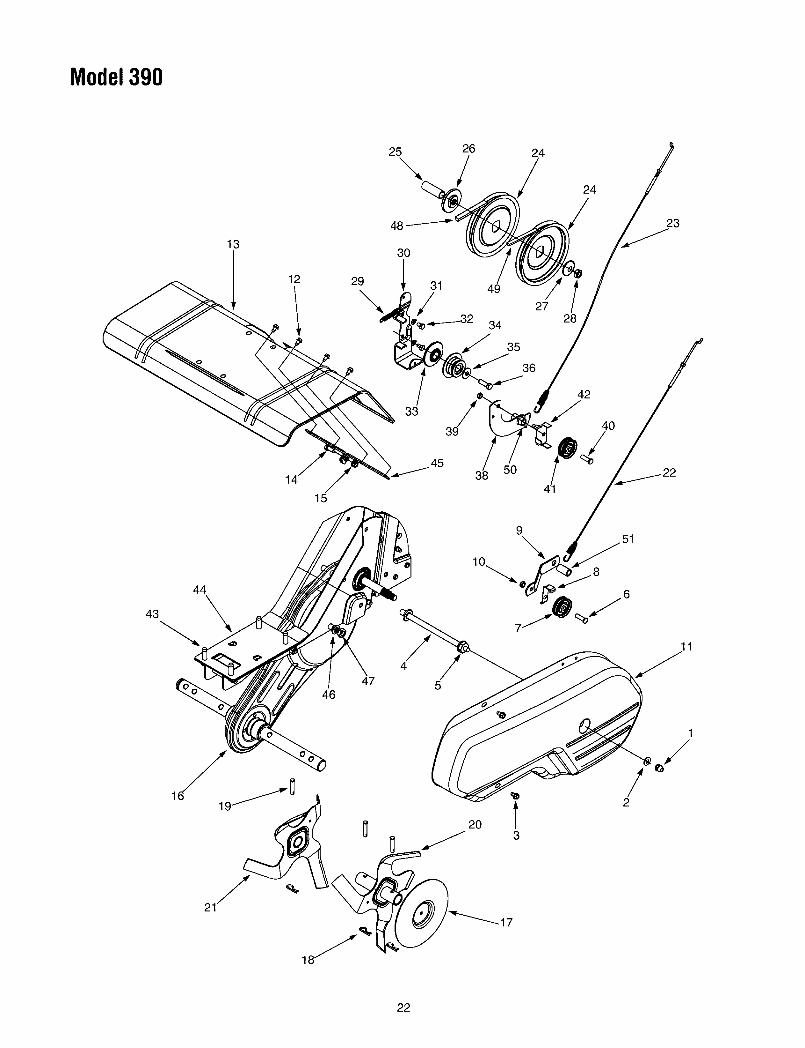
Model390
25
\26
/24
24
13
12 29
48
30
/
33
49
27
3428
42
40
23
15
3/8 50
44
43 \
4647
20 l 2
S 3
22

Model390
REENO.
123456789
1011121314151617181920
21
222324
PART NO. DESCRIPTION
712-0392736-3020710-0599711-0920712-3004A710-0723756-0313786-0149786-0144712-0266786-0057710-0599786-0043A710-3008712-3004A686-0091686-0106714-0149B711-0415642-0023642-0024642-0003642-0002746-0918746-0953756-0585
Hex L-Stop nut 1/4-28Flat Wash..266" I.D. x .625" O.D.
Hex Washer TT-Tap Scr. 1/4-20 x .5"Belt Cover Bolt
Hex Flange Top L-Nut 5/16-18 (Gr.5)Hex Hd. Scr. 3/8-16 x 1.25" Lg. (Gr.5)Fl-ldler 2.12" O.D.
Idler Belt KeeperIdler BracketHex Cent. Jam Nut 3/8-16 Thd.Belt Cover
Hex Wash. TT-Tap Scr. 1/4-20 x .5" Lg.Tiner Shield
Hex Hd. Cap Scr. 5/16-18 x .75" LgHex Flange Top L-Nut 5/16-18 (Gr. 5)Chain Case Assembly CompleteTine Disc EndsInternal Cotter PinClevis Pin
Outer Tine Assembly L.H.Outer Tine Assembly R.H.
Inner Tine Assembly L.H.Inner Tine Assembly R.H.Forward Clutch CableReverse Clutch Cable
FI-Pulley 6" Dia.
REElPART NO.
NO. I
25 1750-0892
26 1748-035027 1736-0112
28 1712-302929 1732-069730 1786-0040B31 1736-0119
32 1710-010733 1756-097134 1756-060035 1736-045236 1710-019138 1686-001339 1712-026640 1710-072341 1756-031342 1786-004143 1710-0502A44 1786-0145A45 1786-005346 1736-017147 1712-024048 1754-042849 1754-042950 1738-010251 1738-0930
DESCRIPTION
Spacer .64" Dia. x 2.4" Lg.Pulley Mounting AdapterBell-Wash..525" I.D. x 1.5" O.D.
Hex Jam Nut 1/2-20 Thd. (Gr. 5)Return SpringReverse BracketLock Washer 5/16Hex Bolt 5/16-24 x .5"
Inner Engine Pulley HalfOuter Engine Pulley HalfBell Washer .396" I.D. x 1/14" O.D.Hex Bolt 3/8-24 x 1.25"
Reverse Arn AssemblyHex Cent. Jam Nut 3/8-16 Thd.
Hex Cap Bolt 3/8-16 x 1.25" Lg. (Gr. 5)Fl-ldler 2.12" O.D.
Keeper PlateHex L-Wash. TT-Tap 3/8-16 x 1.25"
Engine PlateTine Shield BracketL-Wash. 7/16" I.D.Hex Nut 7/16-20 Thd.
V-Belt (Forward)V-Belt (Reverse)Shld. BoltShld. Bolt
23
MANUFACTURER'S LIMITED WARRANTY FOR:
YARDMACHINESThe limited warranty set forth below is given by MTD
PRODUCTS INC ("MTD") with respect to new merchan-
dise purchased and used in the United States, its posses-sions and territories.
MTD warrants this product against defects in material and
workmanship for a period of two (2) years commencing on
the date of original purchase and will, at its option, repair or
replace, free of charge, any part found to be defective in
material or workmanship. This limited warranty shall only
apply if this product has been operated and maintained in
accordance with the Operator's Manual furnished with the
product, and has not been subject to misuse, abuse, com-
mercial use, neglect, accident, improper maintenance,
alteration, vandalism, theft, fire, water or damage because
of other peril or natural disaster. Damage resulting from the
installation or use of any accessory or attachment not
approved by MTD Products Inc. for use with the product(s)
covered by this manual will void your warranty as to any
resulting damages.
Normal wear parts or components thereof are subject to
separate terms as follows: All normal wear part or compo-
nent failures will be covered on the product for a period of
90 days regardless of cause. After 90 days, but within the
two year period, normal wear part failures will be covered
ONLY IF caused by defects in material or workmanship of
OTHER component parts. Normal wear parts and compo-
nents include, but are not limited to, belts, blades, blade
adapters, grass bags, rider deck wheels, seats, snow
thrower skid shoes, shave plates and tires. Batteries are
covered by a 90-day limited replacement warranty.
HOW TO OBTAIN SERVICE: Warranty service is avail-
able, WITH PROOF OF PURCHASE THROUGH YOUR
LOCAL AUTHORIZED SERVICE DEALER. To locate the
dealer in your area, please check for a listing in the Yellow
Pages or contact the Customer Service Department of
MTD PRODUCTS INC by calling 1-800-800-7310 or writ-
ing to P.O. Box 368022, Cleveland, Ohio 44136-9722.
This limited warranty does not provide coverage in the
following cases:a.The engine or component parts thereof. These items
carry a separate manufacturer's warranty. Pleaserefer to the applicable manufacturer's warranty onthese items.
b. Log splitter pumps, valves and cylinders have a sepa-rate one year warranty.
c. Routine maintenance items such as lubricants, filters,
blade sharpening and tune-ups, or adjustments suchas brake adjustments, clutch adjustments or deckadjustments; and normal deterioration of the exteriorfinish due to use or exposure.
d. MTD does not extend any warranty for products soldor exported outside of the United States of America,
its possessions and territories, except those soldthrough MTD's authorized channels of export distribu-tion.
No implied warranty, including any implied warranty of
merchantability or fitness for a particular purpose,
applies after the applicable period of express written
warranty above as to the parts as identified. No other
express warranty or guaranty, whether written or oral,
except as mentioned above, given by any person or
entity, including a dealer or retailer, with respect to any
product shall bind MTD. During the period of the War-
ranty, the exclusive remedy is repair or replacement of
the product as set forth above. (Some states do not
allow limitations on how long an implied warranty lasts, so
the above limitation may not apply to you.)
The provisions as set forth in this Warranty provide the
sole and exclusive remedy arising from the sales. MTD
shall not be liable for incidental or consequential loss
or damages including, without limitation, expenses
incurred for substitute or replacement lawn care ser-
vices, for transportation or for related expenses, or for
rental expenses to temporarily replace a warranted
product. (Some states do not allow the exclusion or limita-
tion of incidental or consequential damages, so the above
exclusion or limitation may not apply to you.)
In no event shall recovery of any kind be greater than the
amount of the purchase price of the product sold. Alteration
of the safety features of the product shall void this War-
ranty. You assume the risk and liability for loss, damage, or
injury to you and your property and/or to others and their
property arising out of the use or misuse or inability to use
the product.
This limited warranty shall not extend to anyone other than
the original purchaser, original lessee or the person for
whom it was purchased as a gift.
How State Law Relates to this Warranty: This limitedwarranty gives you specific legal rights, and you may alsohave other rights which vary from state to state.