operating manual for solar applications
TRANSCRIPT

805-0015 REV C
1. Safety 2
1.1 Warnings, Cautions and Notes 2
1.2 General Warning 2
1.3 Fire Risk 2
1.4 Electric Shock Risk 2
1.5 Chemical Risk 3
1.6 Do’s 3
1.7 Do Not’s 3
1.8 Transportation Warning 3
2. Battery Operating Limits 4
2.1 Maximum Battery Operating Limits 4
2.2 Current Protections 4
2.3 Recommended Battery Operating Limits 4
3. Design Features & Components 5
3.1 Integrated Battery Management System (BMS) 5
3.2 Internal Battery Fuse 5
3.3 Protections 5
4. Handling 5
5. Installation 6
5.1 Tools 6
5.2 Battery Location 6
5.3 Securing Battery 6
5.4 Installation 6
5.5 Parallel Battery Wiring 7
6. Networking 8
6.1 AEBus Network 8
6.2 Configuration with Power Conversion and Monitoring Devices
8
7. Operation 8
7.1 On-Off / Reset 8
7.2 Charging 9
7.3 Charge Curve 9
7.4 Discharging 10
7.5 Storage 10
8. Service & Maintenance 10
8.1 Warranty Registration 10
8.2 Inspection 10
8.3 Battery Firmware 11
9. Recycling and Disposal 11
10. 44-24-2800 Technical Specifications 12
11. 42-48-6650 Technical Specifications 13
44-24-2800
Operating ManualFor Solar Applications
4-13511 Crestwood Place,Richmond, BC, V6V 2E9, Canadadiscoverbattery.com
42-48-6650

2 discoverbattery.com
1. Safety
1.1 Warnings, Cautions, Notes and Symbols
▲ WARNING
Important information regarding possible personal injury.
▲ CAUTIONImportant information regarding possible equipment damage.
▲ NOTEAdditional information concerning important
procedures and features of the battery.
1.2 General Warning
▲ CAUTIONIt is important to operate the device with care
to avoid undesirable consequences.
Do not throw in the garbage. Do not dispose in fire.
Use personal protective equipment when working with batteries.
WARNING - To reduce the risk of injury, user must read instruction manual. Read all the instructions before installation, operation and maintenance.
This product must be recycled and is made of recycled products.
▲ CAUTIONDo not disassemble or modify the battery. If the battery housing is
damaged, do not touch exposed contents.
1.3 Fire Risk
▲ WARNINGRisk of fire - No user serviceable parts inside.
• The AES Battery has a Battery Management System (BMS) with integrated solid state relay to reduce the risk of fire.• Primary suppression for a lithium battery fire is water, the secondary suppression is CO2 powder and halon.
1.4 Electric Shock Risk
▲ WARNINGFor wet and electrically uninsulated working conditions, electric
shock risk is high, and can cause injury and death.
Model Nominal System Voltage Maximum System Voltage44-24-2800 24 V 29.2 V
42-48-6650 48 V 58.4 V

3 discoverbattery.com
1.5 Chemical Risk
▲ WARNINGLithium batteries are a chemical risk if misoperated,
mishandled or abused.
1.6 Do’s• Do protect terminals from short circuit before, during, and after installation• Do wear electrically insulated gloves• Do use electrically insulated tools• Do wear eye protection• Do wear safety toe boots / shoes• Do handle battery carefully• Do secure battery safely• Do always assume battery terminals are energized
1.7 Do Not’s• Do not immerse battery in water• Do not lift or carry the battery during usage or operation • Do not operate or store battery outside of operating limits• Do not short circuit battery• Do not puncture battery• Do not expose battery to flames, or incinerate• Do not open battery case or disassemble battery• Do not wear rings, watches, bracelets or necklaces when handling or working near battery• Do not drop or crush battery• Do not lift battery by the terminal cables• Do not vibrate battery• Do not expose battery to water or other fluids• Do not expose battery to direct sunlight• Do not dispose of battery• Do not connect with other types of batteries• Do not expose battery to high temperatures• Do not install with other battery types or brands
1.8 TransportationIf the battery is not installed in equipment, it must be transported in the original package or equivalent.
Batteries are tested according to UN Handbook of Tests and Criteria, part III, sub section 38.3 (ST/SG/AC. 10/11/Rev.5). For transport the batteries belong to category UN3480, Class 9.
4 discoverbattery.com
2. Battery Operating Limits
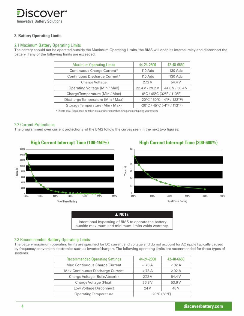
2.1 Maximum Battery Operating LimitsThe battery should not be operated outside the Maximum Operating Limits, the BMS will open its internal relay and disconnect the battery if any of the following limits are exceeded.
Maximum Operating Limits 44-24-2800 42-48-6650Continuous Charge Current* 110 Adc 130 Adc
Continuous Discharge Current* 110 Adc 130 Adc
Charge Voltage 27.2 V 54.4 V
Operating Voltage (Min / Max) 22.4 V / 29.2 V 44.8 V / 58.4 V
Charge Temperature (Min / Max) 0°C / 45°C (32°F / 113°F)
Discharge Temperature (Min / Max) -20°C / 50°C (-4°F / 122°F)
Storage Temperature (Min / Max) -20°C / 45°C (-4°F / 113°F)* Effects of AC Ripple must be taken into consideration when sizing and configuring your system.
2.2 Current Protections The programmed over current protections of the BMS follow the curves seen in the next two figures:
▲ NOTE!
Intentional bypassing of BMS to operate the battery outside maximum and minimum limits voids warranty.
2.3 Recommended Battery Operating LimitsThe battery maximum operating limits are specified for DC current and voltage and do not account for AC ripple typically caused by frequency conversion electronics such as inverter/chargers. The following operating limits are recommended for these types of systems.
Recommended Operating Settings 44-24-2800 42-48-6650Max Continuous Charge Current < 78 A < 92 A
Max Continuous Discharge Current < 78 A < 92 A
Charge Voltage (Bulk/Absorb) 27.2 V 54.4 V
Charge Voltage (Float) 26.8 V 53.6 V
Low Voltage Disconnect 24 V 48 V
Operating Temperature 20°C (68°F)
High Current Interrupt Time (100-150%)
% of Fuse Rating
110% 120% 130%100% 140% 150% 160%
% of Fuse Rating
200% 300% 400% 500% 600% 700%
High Current Interrupt Time (200-600%)

5 discoverbattery.com
3. Design Features & Components
3.1 Integrated Battery Management System (BMS)Monitors
• Cell module voltage• Battery voltage• Battery current• Battery temperature• Battery state of charge (SOC)• Battery energy throughput
Module Balancing• Performs balancing of cell modules
Protection and Operating Limits• BMS will open its internal relay when maximum operating limits are exceeded• When the condition returns to its nominal operating range, most protections will be released and reset after 120s
Communication Ports• Isolated USB and CAN communication
Data Logging• Logged data is accessed using AES Dashboard software via the USB port (Win64 supported)
3.2 Internal Battery FuseThe internal battery fuse provides back-up over-current protection. External fusing should be sized correctly to protect the circuit and circuit cabling.
• A blown fuse requires replacement by a qualified installer - contact your Discover Batter installer.
3.3 ProtectionsThe BMS will open the internal relay to protect against operation outside of maximum specifications. During a protection the key LED will flash at 1 Hz (Hardware version 0.0.0.1 models will sound a buzzer, but not flash the key LED). Most protections will automatically recover once the condition is cleared with the exception of the low voltage protection.
Protection Auto Recoverable Description
Over Voltage YesProtection is triggered when any cell module voltage exceeds the threshold value for 5 seconds. After the voltage falls below the trigger for 120 seconds the protection is cleared.
Under Voltage No Protection is triggered when any cell module voltage falls below the threshold value for 5 seconds. The battery will turn itself off after 120s.
High Current Yes Protection is triggered when current exceeds the threshold value. The protection will be cleared after 120 seconds.
High Temperature YesProtection is triggered when the battery temperature exceeds the threshold value for 5 seconds. After the temperature falls below the recovery temperature the protection is cleared.
Low Temperature YesProtection is triggered when the battery temperature falls below the threshold value for 5 seconds. After the temperature raises above the recovery temperature the protection is cleared.
4. Handling▲ WARNING!
Read Safety Section before installing the battery.
• Battery should be set to OFF• Battery cables should be disconnected• Battery terminals should be protected• Battery handle should be used to lift battery• Battery should be handled by two people or mechanical lift equipment• Do not lift or carry the battery during usage or operation
6 discoverbattery.com
5. Installation ▲ WARNING!
Read Safety Section before installing the battery.
▲ CAUTION!
Do not install AES LiFePO4 batteries in series. Select the appropriate AES battery model for the voltage of your system.
5.1 Tools• Insulated tools must be used• Voltmeter• Post cleaner and wire brush• Personal protective equipment
5.2 Battery LocationLocate the batteries close to the power conversion device in order to minimize the length of the battery cables. Care shouldbe taken to ensure adequate clearance above the batteries is maintained for access to both battery and power conversiondevice connections and disconnects.
Protection from exposure to water, including water sprayed from nozzles, should be ensured.
AES Battery performance and service life will be optimized when they are operated in an ambient temperature of 15°C to 25°C (59°F to 77°F). Care should be taken to ensure that the battery’s temperature is > 0°C (32°F) during charging.
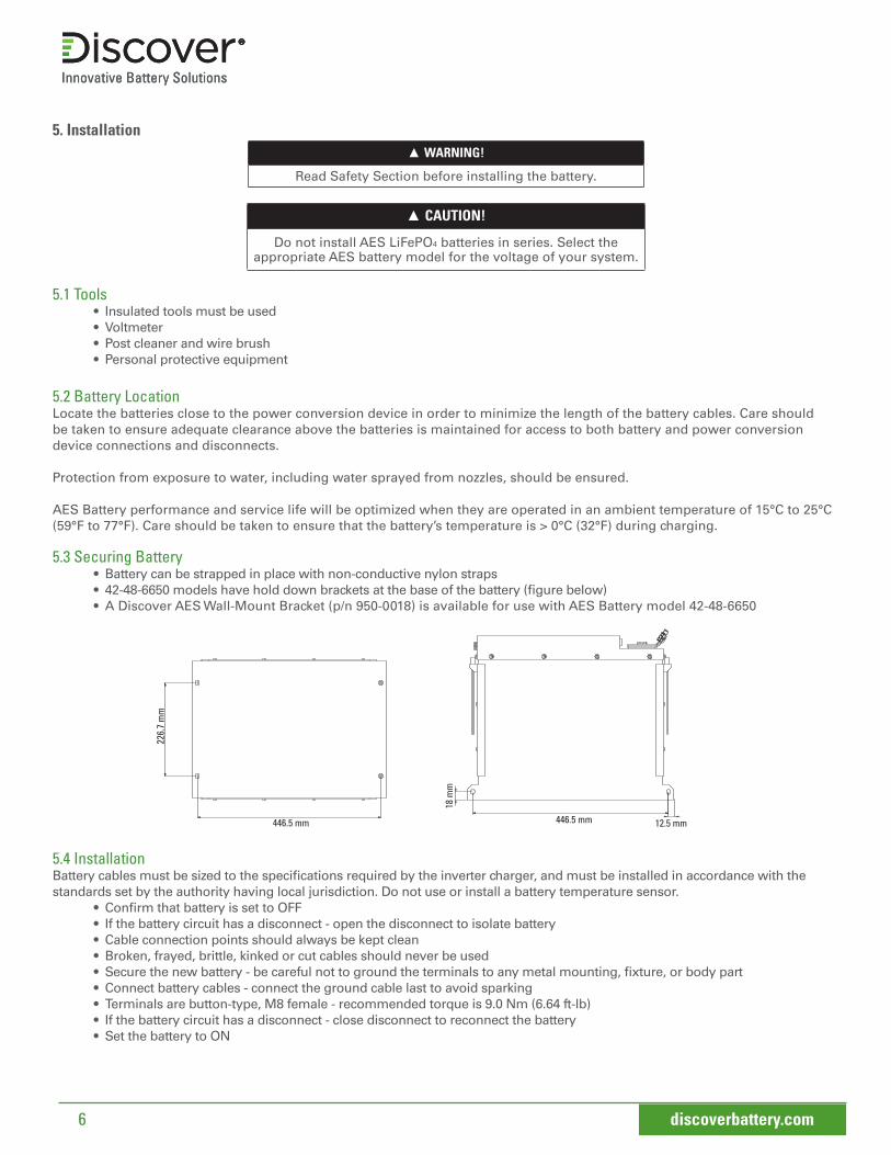
5.3 Securing Battery• Battery can be strapped in place with non-conductive nylon straps• 42-48-6650 models have hold down brackets at the base of the battery (figure below)• A Discover AES Wall-Mount Bracket (p/n 950-0018) is available for use with AES Battery model 42-48-6650
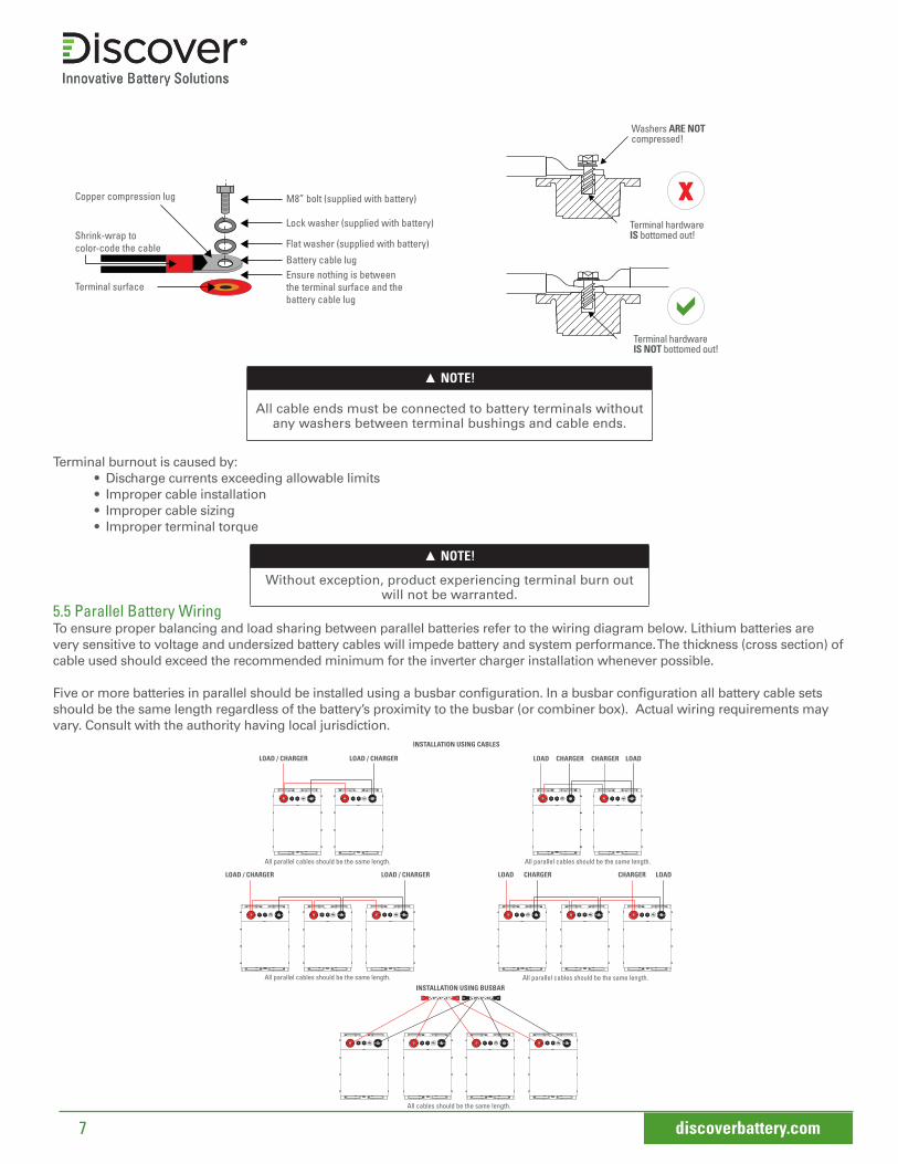
M8” bolt (supplied with battery)Copper compression lug
Shrink-wrap to color-code the cable
Terminal surface
Lock washer (supplied with battery)
Flat washer (supplied with battery)
Battery cable lug Ensure nothing is between the terminal surface and the battery cable lug
5.4 InstallationBattery cables must be sized to the specifications required by the inverter charger, and must be installed in accordance with the standards set by the authority having local jurisdiction. Do not use or install a battery temperature sensor.
• Confirm that battery is set to OFF• If the battery circuit has a disconnect - open the disconnect to isolate battery• Cable connection points should always be kept clean• Broken, frayed, brittle, kinked or cut cables should never be used • Secure the new battery - be careful not to ground the terminals to any metal mounting, fixture, or body part• Connect battery cables - connect the ground cable last to avoid sparking• Terminals are button-type, M8 female - recommended torque is 9.0 Nm (6.64 ft-lb)• If the battery circuit has a disconnect - close disconnect to reconnect the battery• Set the battery to ON
226.
7 m
m
446.5 mm 446.5 mm
18 m
m
12.5 mm
7 discoverbattery.com
▲ NOTE!
All cable ends must be connected to battery terminals without any washers between terminal bushings and cable ends.
Terminal burnout is caused by:• Discharge currents exceeding allowable limits• Improper cable installation• Improper cable sizing• Improper terminal torque
▲ NOTE!
Without exception, product experiencing terminal burn out will not be warranted.
5.5 Parallel Battery WiringTo ensure proper balancing and load sharing between parallel batteries refer to the wiring diagram below. Lithium batteries are very sensitive to voltage and undersized battery cables will impede battery and system performance. The thickness (cross section) of cable used should exceed the recommended minimum for the inverter charger installation whenever possible.
Five or more batteries in parallel should be installed using a busbar configuration. In a busbar configuration all battery cable sets should be the same length regardless of the battery’s proximity to the busbar (or combiner box). Actual wiring requirements may vary. Consult with the authority having local jurisdiction.
LOAD / CHARGER LOAD / CHARGER
LOAD / CHARGER LOAD / CHARGER
CHARGER CHARGER
INSTALLATION USING BUSBAR
CHARGER CHARGERLOAD LOAD
LOAD LOAD
All parallel cables should be the same length. All parallel cables should be the same length.
All parallel cables should be the same length. All parallel cables should be the same length.
All cables should be the same length.
INSTALLATION USING CABLES
M8” bolt (supplied with battery)Copper compression lug
Shrink-wrap to color-code the cable
Terminal surface
Lock washer (supplied with battery)
Flat washer (supplied with battery)
Battery cable lug Ensure nothing is between the terminal surface and the battery cable lug
Terminal hardware IS NOT bottomed out!
Terminal hardware IS bottomed out!
Washers ARE NOT compressed!Washers ARE NOT compressed!
Terminal hardware IS bottomed out!
Terminal hardware IS NOT bottomed out!

8 discoverbattery.com
5.6 Commissioning Parallel SystemsWhen commissioning a system with parallel batteries ensure that all batteries are charged to 100% State of Charge (SOC) before setting all batteries to ON.
▲ CAUTION!
Failure to ensure all batteries are at equal SOC when commisioning a paralleling system may result in blown battery fuses.
Before energizing power electronics ensure that all batteries are set to ON.
6. Networking
6.1 AEBus NetworkThe AEBus is utilized by all networked AES batteries to coordinate all voltage, temperature, and current data. Network Terminators are required for proper functioning of the AES network. Care should be taken to ensure they are installed.
6.2 Configuration with Power Conversion and Monitoring DevicesAES batteries must be set up to work with Power Conversion and Monitoring devices in either an Open Loop or Closed Loop configuration. The charge and discharge settings in a Open Loop configuration are set up through the controller of the Power Conversion device at the time of installation. In a Closed Loop configuration, charge and discharge settings are dynamically controlled by the BMS of the AES Battery over a connection with the Power Conversion device network. Closed Loop communication with a Power Conversion device network requires the use of a LYNK Gateway Communication device (p/n 950-0015) available from Discover Battery.
For Closed Loop and Open Loop configuration details please refer to the appropriate Application Note for your Power Conversion device available from the Discoverbattery.com website, or contact your Discover Battery provider for assistance.
Note: Schneider Electric Conext branded devices communicate over Xanbus forming a Closed Loop configuration using the Xanbus port located on the AES battery and do not require the use of a LYNK Gateway Communication device (p/n 950-0015). Refer to Application Note 885-0013 Closed Loop Integration with Xanbus Enabled Schneider Electric Conext Products, for detailed instructions.
7. Operation▲ CAUTION!
Review operating limits.
7.1 On–Off / Reset• To set the battery to ON momentarily press the button - the LED will illuminate• To set the battery to OFF momentarily press the button - the LED will darken
9 discoverbattery.com
7.2 Charging Before charging the battery make sure to read and understand the instructions that come with the Power Conversion device. Never attempt to charge a battery without first reviewing and understanding the instructions for the Power Conversion device being used. Do not use or install a battery temperature sensor.
▲ CAUTION!
Always make sure the chargers charging curve meets the battery’s charging requirement; never charge a visibly damaged battery; never
charge a frozen battery.
1. Connect the Power Conversion device’s charger leads to the battery.2. Ensure the charger and battery side connections are tight.3. Set the charger to ON4. Set the battery to ON
▲ CAUTION!
NOT ALL CHARGERS ARE CAPABLE OF CHARGING LITHIUM BATTERIESCONFIRM that your chosen charger is incapable of producing transient spikes that exceed the published terminal voltage limits for the battery.
Spikes are fast, short duration electrical transients in voltage (voltage spikes), current (current spikes), or transferred energy (energy spikes) in an electrical circuit. Voltage spikes usually happen when the AC/DC adapter is plugged in, or charge current is cut off quickly. Multi voltage chargers are constructed using transformers that may be capable of producing spikes that exceed the maximum ratings of the Discover AES Battery. You must ensure that the charger being supplied:
• Meets the recommended charge curve • Incapable of exceeding Discover’s maximum terminal voltages
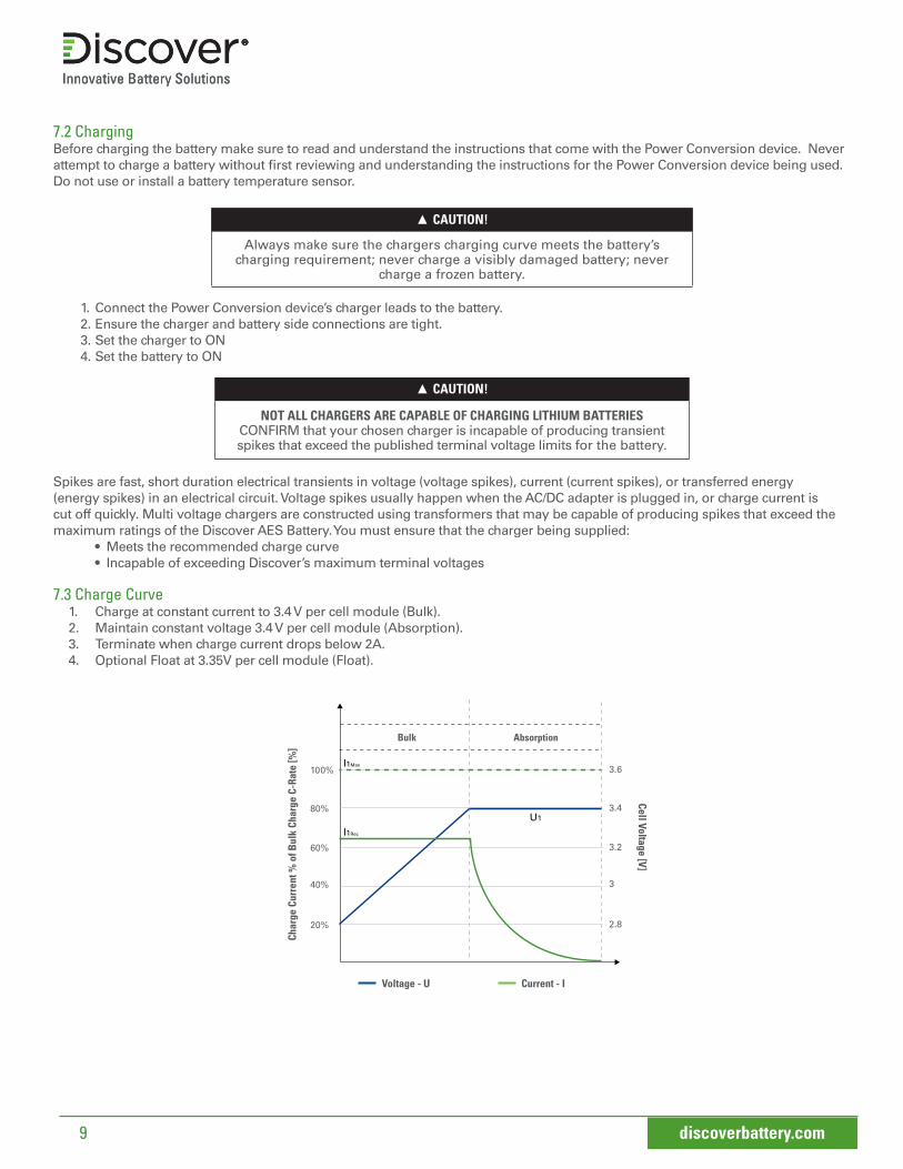
7.3 Charge Curve 1. Charge at constant current to 3.4 V per cell module (Bulk).2. Maintain constant voltage 3.4 V per cell module (Absorption). 3. Terminate when charge current drops below 2A.4. Optional Float at 3.35V per cell module (Float).
Absorption
Char
ge C
urre
nt %
of B
ulk
Char
ge C
-Rat
e [%
]
Voltage - U Current - I
Bulk
Cell Voltage [V]
2.820%
40%
60%
80%
100%
3
3.2
3.4
3.6I1Max
I1Rec
U1

10 discoverbattery.com
▲ CAUTION!
Do not charge battery higher than 3.4 V per cell module.
▲ NOTE!
Recommended charge current is 0.5C
Model Cell Modules in Series Bulk Current Bulk
VoltageTermination
Charge Current
44-24-2800 8S 110 Adc maximum 27.2 VI2 ≤ 2 A
42-48-6650 16S 130 Adc maximum 54.4 V
7.4 Discharging• Set the battery to ON• Set the load to ON• Recommended low voltage cut off: 24 V | 48 V
▲ NOTE!
Do not discharge battery below recommended minimum operating voltages.
▲ NOTE!
Do not discharge battery at rates greater than recommended operating currents.
7.5 StorageSystems should be stored out of direct sunlight under the following temperature conditions:
Minimum Storage Temperature -20°C / -4°F
Maximum Storage Temperature 45°C / 113°F
Systems should be put into storage at 80% SOC and checked monthly to ensure SOC does not fall below 20%.At 20% SOC the battery will self discharge in approximately 2 months.
▲ CAUTION!
Do not store a discharged battery. Recharge battery after every use. Batteries that have self-discharged to a severely
discharge state are not recoverable.
8. Service & Maintenance
8.1 Warranty RegistrationTo register your product you will need the serial number of the battery. Visit discoverbattery.com for registration details.
8.2 InspectionBatteries should be carefully inspected on a regular basis in order to detect and correct potential problems before they do harm. This routine should be started when the batteries are first received.
• Inspect for cracks in the battery casing• Check battery terminals and connections to make sure they are clean, free of dirt, fluids and corrosion• All battery cables and their connections should be tight, intact, and NOT broken or frayed • Replace any damaged batteries • Replace any damaged cables • Ensure correct torque is used for the terminal bolts

11 discoverbattery.com
8.3 Battery FirmwareConsult the Discoverbattery.com website for the latest battery firmware versions. If a battery firmware update is require, ensure this is done by a qualified and authorized person using the AES Dashboard software tool.
9. Recycling and DisposalBatteries must not be mixed with domestic or industrial waste. Discover AES batteries are recyclable and must be processed through a recognized recycling agency or dealer. Please contact Discover or your servicing dealer for details.

12 discoverbattery.com
Electrical SpecificationsNominal Voltage 25.6 V
Charge Voltage 27.2 V
Maximum Voltage 29.2 V
Minimum Voltage 20 V
Nominal Capacity 110 Ah
Nominal Energy 2816 Wh
Max Continuous Charge Current 110 Adc
Max Continuous Discharge Current 110 Adc
Fuse - Provides backup over-cur-rent protection
Hardware 0.0.0.1 150 A
Hardware 0.0.0.2 200 A
Cell Chemistry LiFePO4
Cell Modules 8S 22P
Self-Discharge 25°C / 77°F < 3% per month (battery off)
Fault LimitsOver Temperature - Discharge Protection > 60°C/140°F for 5s
Over Temperature - Charge Protection > 60°C/140°F for 5s
Low Temperature - Discharge Protection < -20°C/-4°F for 5s
Low Temperature - Charge Protection < 0°C/32°F for 5s
Over Voltage Protection> 3.65 V in any cell module for 5s
Under Voltage Protection< 2.5 V in any cell module for 5s
Over Current Protection Based on Fuse (Section 2.2)
Mechanical SpecificationsBattery Dimensions (HxWxD) 276 x 347.5 x 329.5 mm
Battery Weight 40 kg
Shipping Dimensions (HxWxD) 470 x 430 x 390 mm
Shipping Weight 48.4 kg
Terminal M8
Terminal HardwareM8 Stainless Steel Bolt, Flat Washer, Lock Washer (Supplied)
Terminal Torque 9.0 Nm +/- 3
Case MaterialPowder Coated Cold Rolled Steel
Enclosure IP Rating IP 55
Charge Temperature Range 0°C/45°C (32°F/113°F)
Discharge Temperature Range -20°C/50°C (-4°F/122°F)
Storage Temperature Range -20°C/45°C (-4°F/113°F)
Operational SpecificationsBattery Management System (BMS) Integrated, with Solid State
Relay (SSR)
Cell Balancing Passive balancing when Cell Voltage > 3.35 V
Non-Volatile Memory Yes
Lifetime Logged Data • Time• High/low average cell module voltage• Balancing, Fault and Relay State• Battery SOC, Current, Voltage, Temperature• Charge Energy In/Out
Communication Ports • Isolated USB• Isolated CAN (AEBus)• Isolated XANBUS
Communication Connectors USB Type A FemaleRJ45 Jack x2
RJ45 AEBus
12. 44-24-2800 TECHNICAL SPECIFICATIONS
Regulatory Approvals UN 38.3, IEC 62133, UL 2271, UL 1973
Pin 1* AEBus +12 V
Pin 2* AEBus +12 V
Pin 3 AEBus GND
Pin 4 AEBus CAN Low
Pin 5 AEBus CAN High
Pin 6 AEBus +5V
Pin 7* AEBus GND
Pin 8* AEBus GND
*0.0.0.2 Hardware only

13 discoverbattery.com
Electrical SpecificationsNominal Voltage 51.2 V
Charge Voltage 54.4 V
Maximum Voltage 58.4 V
Minimum Voltage 40 V
Nominal Capacity 130 Ah
Nominal Energy 6656 Wh
Max Continuous Charge Current 130 Adc
Max Continuous Discharge Current 130 Adc
Fuse - Provides backup over-cur-rent protection
Hardware 0.0.0.1 150 A
Hardware 0.0.0.2 200 A
Cell Chemistry LiFePO4
Cell Modules 16S 26P
Self-Discharge 25°C / 77°F < 3% per month (battery off)
Fault LimitsOver Temperature - Discharge Protection > 60°C/140°F for 5s
Over Temperature - Charge Protection > 60°C/140°F for 5s
Low Temperature - Discharge Protection < -20°C/-4°F for 5s
Low Temperature - Charge Protection < 0°C/32°F for 5s
Over Voltage Protection> 3.65 V in any cell module for 5s
Under Voltage Protection< 2.5 V in any cell module for 5s
Over Current Protection Based on Fuse (Section 2.2)
Mechanical SpecificationsBattery Dimensions (HxWxD) 375 x 347.5 x 471.5 mm
Battery Weight 87 kg
Shipping Dimensions (HxWxD) 570 x 440 x 570 mm
Shipping Weight 98.9 kg
Terminal M8
Terminal HardwareM8 Stainless Steel Bolt, Flat Washer, Lock Washer (Supplied)
Terminal Torque 9.0 Nm +/- 3
Case MaterialPowder Coated Cold Rolled Steel
Enclosure IP Rating IP 55
Charge Temperature Range 0°C/45°C (32°F/113°F)
Discharge Temperature Range -20°C/50°C (-4°F/122°F)
Storage Temperature Range -20°C/45°C (-4°F/113°F)
Operational SpecificationsBattery Management System (BMS) Integrated, with Solid State
Relay (SSR)
Cell Balancing Passive balancing when Cell Voltage > 3.35 V
Non-Volatile Memory Yes
Lifetime Logged Data • Time• High/low average cell module voltage• Balancing, Fault and Relay State• Battery SOC, Current, Voltage, Temperature• Charge Energy In/Out
Communication Ports • Isolated USB• Isolated CAN (AEBus)• Isolated XANBUS
Communication Connectors USB Type A FemaleRJ45 Jack x2
13. 42-48-6650 TECHNICAL SPECIFICATIONS
RJ45 AEBus
Regulatory Approvals UN 38.3, IEC62133, UL 2271, UL 1973
Pin 1* AEBus +12 V
Pin 2* AEBus +12 V
Pin 3 AEBus GND
Pin 4 AEBus CAN Low
Pin 5 AEBus CAN High
Pin 6 AEBus +5V
Pin 7* AEBus GND
Pin 8* AEBus GND
*0.0.0.2 Hardware only